

 Manufacturers
TE CONNECTIVITY 1461139-5

Description
Power Relay 24VDC 16A SPST-NO(24.3x11.6x26.7)mm THT
1461139-5
Part Number
1461139-5
Price
Request Quote
Manufacturer
TE CONNECTIVITY
Lead Time
Request Quote
Category
Relays and I/O Modules » Power Relay
Specifications
Manufacturer
TE Connectivity
Manufacturers Part #
1461139-5
Industry Aliases
PCKWK-124D2M,000
Sub-Category
Power Relays
Brand
AMP
Factory Pack Quantity
50
Datasheet
DDEController?Action=showdoc&DocId=Catalog+Section%7F1308242_GPR_Catalog_Americas%7F0303%7Fpdf%7FEnglish%7FENG_CS_1308242_GPR_Catalog_Americas_0303.pdf
14567 KiB

Extracted Text
Catalog 1308242 Revised 3-03 Relays, Contactors, Timers, Transformers and Circuit Breakers For General Purpose Applications
Relays, Contactors, Timers,
AGASTAT
TYCO ELECTRONICS CORPORATION
WWW.TYCOELECTRONICS.COM Transformers and Circuit Breakers
AXICOM
For General Purpose Applications
Catalog 1308242 Revised 3-03 KILOVAC
OEG
P&B
PRODUCTS UNLIMITED
SCHRACK
This page intentionally left blank.
Relays, Contactors, Timers, Transformers and
Circuit Breakers for General Purpose
Industrial & Commercial Applications
This technical databook includes specification information for a broad selection of components. Electrome-
chanical relays, contactors, timers, solid state relays, input/output modules, sensors, protective relays,
magnetic circuit breakers, thermal circuit breakers and transformers are all described in the databook.
Locating a product in this databook
Immediately following this introductory page is an alphanumeric index of the product series in this databook.
This is helpful if you already know the series designator of the product for which you are seeking specifications.
The index is followed by a selector guide that provides a brief overview of the various series in our extensive
product line. This is intended to help you quickly determine which product series may be best suited for a given
application. The selector guide also lists the page number in the databook where much more detailed
specifications for each series may be found.
Need more help selecting a product series?
The body of this databook is divided into 14 major product categories. Each section begins with an
alphanumeric index of the product series contained therein. Additionally, a "question tree" is included on the
first or second page of several sections to help in narrowing your search to product series that may be
appropropriate for a given application. While by no means definitive, these tools can prove to be an effective
starting point.
Finding out more details
If you need additional specification information , please contact Tyco Electronics Technical Support (see inside
back cover for Technical Support contact information.) Information about our products also can be found on
our website at http://relays.tycoelectronics.com. Our website is updated more frequently than the printed
technical databook, so you may find information there which is more current than our databook.
Note regarding product availability
This databook lists a broad range of products which are available with varying leadtimes. Some are normally
maintained in stock for immediate delivery. Many other products are available within what would be
considered “normal” leadtimes for our industry. However, there may be extended leadtimes for some non-
stock items. Additionally, there are minimum quantity requirements. You should consult with your Tyco
Electronics authorized distributor or sales engineer regarding availability and minimum order requirements
before specifying a particular non-stock model.
Changes in specifications/availability
We constantly endeavor to enhance the quality of our products and update our product offering; therefore,
specifications and product availability are subject to change without notice.
Disclaimer
While Tyco Electronics has made every reasonable effort to ensure the accuracy of the information in this
databook, Tyco Electronics does not guarantee that it is error-free, nor does Tyco Electronics make any other
representation, warranty or guarantee that the information is accurate, correct, reliable or current. Tyco
Electronics reserves the right to make any adjustments to the information contained herein at any time without
notice. Tyco Electronics expressly disclaims all implied warranties (and all express warranties, except as
otherwise stated in this databook) regarding the information contained herein, including but not limited to any
implied warranties or merchantability or fitness for a particular purpose. It is recommended that you test any
new or replacement product before incorporating into a system.
The dimensions in this databook are for reference purposes only and are subject to change without notice.
Dimensions are in inches over (millimeters), unless otherwise specified. Specifications are subject to change
without notice. Consult Tyco Electronics at 1-800-522-6752 for latest dimensions and design specifications,
or use the global contact list shown on inside back cover.
AGASTAT, AMP, AXICOM, CII, HARTMAN, KILOVAC, OEG,
P&B, POTTER & BRUMFIELD, PRODUCTS UNLIMITED,
SCHRACK and TYCO are trademarks.
Other products, logos and company names mentioned herein © 2003 by Tyco Electronics Corporation.
may be trademarks of their respective owners. All rights reserved.
i
Catalog 1308242
Issued 3-03
PRODUCT INDEX
Alphanumeric Index
Series Type Page Series Type Page
Model 2000 ................. Definite Purpose Contactor ...................................................... 828
0409 (Hi-Inrush) .......... 10A, One-pole PC Board Relay ................................................. 488
0410 .............................. 16A, One-pole PC Board Relay ................................................. 491 Model 93-3100 ............ Definite Purpose Contactor ...................................................... 834
Model 96-3100 ............ Definite Purpose Contactor ...................................................... 830
0419 .............................. Relay w/Dust Cover .................................................................... 745
0429 (Hi-Inrush) .......... 10A, One-pole PC Board Relay ................................................. 457 Model 96-3186 ............ Definite Purpose Contactor ...................................................... 838
0430 .............................. 10-16A, One- or Two-pole PC Board Relay ............................ 495 Model 98-3100 ............ Definite Purpose Contactor ...................................................... 832
136 ................................ Traffic Light (Flash Transfer) Relay ......................................... 916 Model A-3100 ............. Definite Purpose Contactor ...................................................... 840
MT ................................ Relay w/Dust Cover .................................................................... 742
159/160 ......................... Mercury-Wetted Reed Relays .................................................. 308
190 ................................ DPDT, THT Low-signal PC Board Relay .................................. 331 MT2 .............................. DPDT, THT Low-signal PC Board Relay .................................. 335
MT4 .............................. 4PDT, THT Low-signal PC Board Relay ................................... 337
2100 .............................. Miniature Electropneumatic Timer ........................................ 1254
2IO ................................ Mtg. Board for Standard I/O Modules .................................. 1114 OAC .............................. Standard AC Output Module ................................................... 1110
OACM .......................... Slim Line AC Output Module ................................................... 1118
2IOM ............................ Mtg. Board for Slim Line I/O Modules .................................. 1122
38 .................................. Power Relay ................................................................................ 818 ODC .............................. Standard DC Output Module ................................................... 1110
ODCM .......................... Slim Line DC Output Module ................................................... 1118
3RP15 ........................... Programmable Time Delay Relay ........................................... 1207
4000 .............................. 5-30VA Transformer, Wire Leads, Class II ............................. 204 OJ/OJE ........................ 3-10A, One-pole PC Board Relay ............................................. 422
OL ................................. SPST-NO & DPST-NO, Dry Reed Relay .................................. 304
4000 .............................. 10-30VA Transformer, QC Terminals, Class II ........................ 205
4000 .............................. 20-40VA Transformer, Plate Mount, Class II .......................... 206 OMI/OMIH .................. 16A, One-pole PC Board Relay ................................................. 458
OMI 2 ........................... 5A, Two-pole PC Board Relay .................................................. 460
4000 .............................. 40-50VA Transformer, Wire Leads, Class II ........................... 207
4000 .............................. 40-50VA Transformer, QC Terminals, Class II ........................ 208 OMIF ............................ 20A, One-pole PC Board Relay ................................................. 466
OMIT ............................ 10A, One-pole PC Board Relay ................................................. 464
4000 .............................. 60-75VA Transformer, Wire Leads, Class II ........................... 209
4000 .............................. 60-75VA Transformer, QC Terminals, Class II ........................ 210 OMR ............................. SPST-NO & DPST-NO, Dry Reed Relay .................................. 306
ORWH .......................... 10A, One-pole PC Board Relay ................................................. 438
4700 .............................. 60-150VA Transformer, Wire Leads, UL 508 ........................... 211
48K ............................... Programmable Time Delay Relay ........................................... 1210 OSA .............................. 3-5A, Two-pole PC Board Relay ............................................... 470
OSZ .............................. 16A, One-pole PC Board Relay ................................................. 472
491 ................................ 20A AC Coil PCB or Panel Mt. Relay ......................................... 509
57 .................................. Transformer Relay for HVAC .................................................... 212 OUAZ ........................... SPDT, THT Low-signal PC Board Relay .................................. 319
OUDH ........................... 10A, One-pole PC Board Relay ................................................. 432
600 ................................ 3-15A, One-pole PC Board Relay ............................................. 497
7000 .............................. Electropneumatic Timer .......................................................... 1248 OZ/OZF ......................... 16A, One-pole PC Board Relay ................................................. 462
P1 (V23026) ................. SPDT, SMT or THT Low-signal PC Board Relay .................... 314
9100 .............................. Power Relay ................................................................................ 816
9400 .............................. Power Relay ................................................................................ 814 P2 (V23079) ................. DPDT, SMT or THT Low-signal PC Board Relay .................... 325
P25 ............................... Definite Purpose Contactor ...................................................... 820
AGASTAT Timer Accessories ........................................................................................ 1206
AGASTAT Timer Terms and Definitions ....................................................................... 1204 P30/P40 ........................ Definite Purpose Contactor ...................................................... 823
P31/P41 ........................ Definite Purpose Contactor ...................................................... 826
AGASTAT Timer Timing Modes ..................................................................................... 1205
Agency Approval Information ............................................................................................. iv PB ................................. 10A, One-pole PC Board Relay ................................................. 426
PCD/PCDF ................... 15A, One-pole PC Board Relay ................................................. 424
Card E (V23057) .......... 8A, One-pole PC Board Relay ................................................... 480
CB ................................. Discrete Function Time Delay Relay ..................................... 1228 PCE ............................... 10A, One-pole PC Board Relay ................................................. 436
PCF ............................... 25A DC Coil PCB Relay ................................................................ 502
CD ................................. Discrete Function Time Delay Relay ..................................... 1222
CG ................................. Discrete Function Time Delay Relay ..................................... 1220 PCG .............................. 5A, Two-pole PC Board Relay .................................................. 493
PCH .............................. 5-10A, One-pole PC Board Relay ............................................. 418
CH ................................. Discrete Function Time Delay Relay ..................................... 1226
CK ................................. Discrete Function Time Delay Relay ..................................... 1224 PCI ................................ 3A, Two-pole PC Board Relay .................................................. 468
PCJ ............................... 5A, One-pole PC Board Relay ................................................... 416
CL ................................. Discrete Function Time Delay Relay ..................................... 1231
CN1 .............................. Discrete Function Time Delay Relay ..................................... 1219 PCK .............................. 16A, One-pole PC Board Relay ................................................. 478
PCKWK ........................ Magnetic Latching Relay .......................................................... 904
CNM5 ........................... Programmable Time Delay Relay ........................................... 1215
CNS .............................. Programmable Time Delay Relay ........................................... 1213 PCL/PCLH .................... Relay w/Dust Cover .................................................................... 713
PCN .............................. 3A, One-pole PC Board Relay ................................................... 407
CNT .............................. Programmable Time Delay Relay ........................................... 1211
Contact Forms & Material .................................................................................................... iv PE ................................. 5A, One-pole PC Board Relay ................................................... 403
PE - Latching .............. Magnetic Latching Relay .......................................................... 902
CR ................................. Discrete Function Time Delay Relay ..................................... 1230
CS ................................. Voltage Sensor .......................................................................... 1302 PM ................................ Power Relay ................................................................................ 809
PMA/PMB ................... Three Phase Power Quality Monitor ..................................... 1305
CU ................................. Discrete Function Time Delay Relay ..................................... 1231
D2N (V23105 ) ............. DPDT, THT Low-signal PC Board Relay .................................. 333 PRD .............................. Power Relay ................................................................................ 811
PT ................................. Relay w/Dust Cover .................................................................... 717
FP2 ............................... DPDT, THT Low-signal PC Board Relay .................................. 323
FT2/FU2 ........................ DPDT, SMT or THT Low-signal PC Board Relay .................... 327 P&B Time Delay Relay Terms & Definitions ................................................................ 1202
P&B Time Delay Relay External Resistor Guide .......................................................... 1203
FX2 ............................... DPDT, THT Low-signal PC Board Relay .................................. 329
GP ................................. Control Relay ............................................................................... 917 R10-R ........................... Immersion-Cleanable Relay ...................................................... 703
R10 ............................... Relay w/Dust Cover .................................................................... 703
High Performance Relay Product Overview ................................................................ 1401
IAC ............................... Standard AC Input Modules ................................................... 1110 RE ................................. 6A, One-pole PC Board Relay ................................................... 405
RM2/3/5/6/7 ................. Relay w/Dust Cover .................................................................... 733
IACM ............................ Slim Line AC Input Modules .................................................... 1118
IDC ............................... Standard DC Input Modules ................................................... 1110 RM C/D ........................ Power Relay ................................................................................ 805
RP II/1 .......................... 8-16A, One-pole PC Board Relay ............................................. 484
IDCM ............................ Slim Line DC Input Modules .................................................... 1118
IF (V23077) ................... 16A, One-pole PC Board Relay ................................................. 489 RP II/2 .......................... 8A, Two-pole PC Board Relay .................................................. 482
RP3SL (Hi-Inrush) ...... 16A, One-pole PC Board Relay ................................................. 486
IM ................................. DPDT, SMT or THT Low-signal PC Board Relay .................... 321
JWD/JWS ................... SPST-NO – DPDT, Dry Reed Relay .......................................... 303 RT - AC Coil ................ 8-16A, One- or two-pole PC Board Relay ............................... 448
RT - DC Coil ................ 8-16A, One- or two-pole PC Board Relay ............................... 446
K10 ............................... Relay w/Dust Cover .................................................................... 720
KA ................................. Open Relay ................................................................................... 737 RT - Sensitive ............ 10A, One-pole PC Board Relay ................................................. 451
RT - Hi-Inrush ............ 16A, One-pole PC Board Relay ................................................. 455
KBP .............................. Mechanical Latching Relay ...................................................... 910
KH/KHA ....................... Relay w/Dust Cover .................................................................... 709 RT - Hi-Temp ............. 10-16A, One-pole PC Board Relay ........................................... 453
RT - Latching .............. Magnetic Latching Relay .......................................................... 906
KHS .............................. Hermetically Sealed Relay ........................................................ 709
KRP–3–H ..................... Relay w/Dust Cover .................................................................... 739 RY II .............................. 8A, One-pole PC Board Relay ................................................... 412
S86R/S87R ................... Power Relay ................................................................................ 807
KR–E ............................ Hermetically Sealed Relay ........................................................ 737
KRP/KRPA ................... Relay w/Dust Cover .................................................................... 737 S89R/S90R ................... Impulse Relay .............................................................................. 912
SCB .............................. Discrete Function Time Delay Relay ..................................... 1235
KU/KUP ........................ Open Relay or Relay w/Dust Cover .......................................... 723
KUE/KUEP ................... Open Relay or Relay w/Dust Cover .......................................... 723 SCE ............................... Discrete Function Time Delay Relay ..................................... 1239
SCF ............................... Programmable Time Delay Relay ........................................... 1218
KUGP ........................... Relay w/Dust Cover .................................................................... 723
KUHP ........................... Power Relay ................................................................................ 803 SDAS-01 ...................... Current Monitor ........................................................................ 1307
SDT .............................. 10A, One-pole PC Board Relay ................................................. 474
KUIP ............................. Relay w/Dust Cover .................................................................... 723
KUL ............................... Magnetic Latching Relay .......................................................... 908 SDT-R .......................... 5-10A, One-pole PC Board Relay ............................................. 476
Selector Guide ........................................................................................................................ v
KUM/KUMP ................ Open Relay or Relay w/Dust Cover .......................................... 723
KUP93 .......................... Relay w/Dust Cover .................................................................... 731 SNR (V23092) .............. 6A, One-pole PC Board Relay ................................................... 409
Socket Usage Guide .......................................................................................................... 749
MD0 ............................. Discrete Function Time Delay Relay ..................................... 1233
MDR ............................. Rotary Relay (High Shock Resistance) ................................... 914 SR2 (V23047) ............... 2 Pole Relay w/ Forcibly Guided Contacts .............................. 603
SR4 D/M ...................... 4 Pole Relay w/ Forcibly Guided Contacts .............................. 606
Micro K (V23086) ........ Single or Dual 20A Automotive Relay .................................... 1002
ML ................................ Magnetic Latching Control Relay ............................................ 917 SR6 (V23050) ............... 6 Pole Relay w/ Forcibly Guided Contacts .............................. 609
Dimensions are shown for Dimensions are in inches over Specifications and availability www.tycoelectronics.com
reference purposes only. (millimeters) unless otherwise subject to change. Technical support:
ii
specified. Refer to inside back cover.
Catalog 1308242
Issued 3-03 PRODUCT INDEX
Series Type Page
SR6D/M ....................... 4 Pole Relay w/ Forcibly Guided Contacts .............................. 607
SR6S ............................ Sensitive 6 Pole Relay w/ Forcibly Guided Contacts ............ 611
Circuit Breakers .........................101-124
SR6Z ............................. 6 Pole Relay w/ Forcibly Guided ContactsModule ................ 613
1
SRC .............................. Discrete Function Time Delay Relay ..................................... 1237
SRUDH ......................... 12A, One-pole PC Board Relay ................................................. 442
SRUUH ......................... 15A, One-pole PC Board Relay ................................................. 444
SSC .............................. Discrete Function Time Delay Relay ..................................... 1234
SSF ............................... Programmable Time Delay Relay ........................................... 1217
Transformers ..............................201-212
2
SSR .............................. Solid State Relay, Paired SCR Output ................................... 1104
SSRD ............................ Dual Solid State Relay ............................................................. 1106
SSRQ ............................ Quad Solid State Relay ............................................................ 1108
SSRT ............................ Solid State Relay, Triac Output .............................................. 1102
SST ............................... Discrete Function Time Delay Relay ..................................... 1238
STA .............................. Discrete Function Time Delay Relay ..................................... 1236 Low-signal PC Board Relays ....301-338
3
T7C ............................... 5-12A, One-pole PC Board Relay ............................................. 440
T7N ............................... 10A, One-pole PC Board Relay ................................................. 434
T72M ............................ Single 20A Automotive Relay .................................................. 1005
T73 ................................ 10A, One-pole PC Board Relay ................................................. 430
T75 ................................ 8-14A, One-pole PC Board Relay ............................................. 414
Mid-Range PC Board Relays ...401-498
T77 ................................ 3-10A, One-pole PC Board Relay ............................................. 420
4
T81 ................................ SPDT, THT Low-signal PC Board Relay .................................. 318
T9A ............................... 30A DC Coil PCB or Panel Mt. Relay ......................................... 506
T90 ................................ 30A DC Coil PCB Relay ................................................................ 504
T92 ................................ 30A AC or DC Coil PCB or Panel Mt. Relay .............................. 511
TR ................................. Timing Control Relay .................................................................. 917
Power PC Board Relays ............501-512
5
Track Mount System .......................................................................................................... 747
TSC ............................... SPDT, THT Low-signal PC Board Relay .................................. 316
U/UB (V23148 ) ........... 7A, One-pole PC Board Relay ................................................... 428
V23026 (P1) ................. SPDT, SMT or THT Low-signal PC Board Relay .................... 314
V23047 (SR2) ............... 2 Pole Relay w/ Forcibly Guided Contacts .............................. 603
Relays with
V23050 (SR6) ............... 6 Pole Relay w/ Forcibly Guided Contacts .............................. 609
6
Forcibly-Guided Contacts .........601-614
V23057 (Card E) .......... 8A, One-pole PC Board Relay ................................................... 480
V23077 (IF) ................... 16A, One-pole PC Board Relay ................................................. 489
V23079 (P2) ................. DPDT, SMT or THT Low-signal PC Board Relay .................... 325
V23086 (Micro K) ........ Single or Dual 20A Automotive Relay .................................... 1002
Plug-in/Panel Mount
V23092 (SNR) .............. 6A, One-pole PC Board Relay ................................................... 409
V23105 (D2N) .............. DPDT, THT Low-signal PC Board Relay .................................. 333
7
General Purpose Relays ...........701-752
V23148 (U/UB) ............ 7A, One-pole PC Board Relay ................................................... 428
V2R ............................... 20A Automotive Motor Reversing Module ........................... 1012
VCA .............................. Single Phase Undervoltage Relay ......................................... 1303
VF4 ............................... 40A Automotive Relay .............................................................. 1017
Power Relays & Definite
VF7 ............................... 70A Automotive Relay .............................................................. 1021
8
VFM .............................. 20A Automotive Relay .............................................................. 1014
Purpose Contactors...................801-942
VKP .............................. 40A Automotive Relay .............................................................. 1007
VMA ............................. Single Phase Undervoltage Relay ......................................... 1304
VTF ............................... Automotive Flasher Module .................................................... 1024
VTM-1 .......................... Discrete Function Timing Module .......................................... 1240
Latching, Impulse, Rotary &
VTM1 ........................... Discrete Function Timing Module .......................................... 1241
9
Special Application Relays ......901-920
VTM2 ........................... Discrete Function Timing Module .......................................... 1244
VTM3 ........................... Discrete Function Timing Module .......................................... 1245
VTM4 ........................... Discrete Function Timing Module .......................................... 1246
VTM7 ........................... Discrete Function Timing Module .......................................... 1247
VTMA1 ......................... Discrete Function Timing Module .......................................... 1242
Automotive Relays .................1001-1026
VTMR1 ......................... Discrete Function Timing Module .......................................... 1243 10
W6 ................................ Magnetic Circuit Breaker .......................................................... 119
W9 ................................ Magnetic Circuit Breaker .......................................................... 119
W23 .............................. Thermal Circuit Breaker ............................................................ 116
W28 .............................. Thermal Circuit Breaker ............................................................ 110
Solid State Relays &
W31 .............................. Thermal Circuit Breaker ............................................................ 116
11
Input/Output Modules ...........1101-1126
W33 .............................. Thermal Circuit Breaker ............................................................ 114
W51 .............................. Thermal Circuit Breaker ............................................................ 112
W54 .............................. Thermal Circuit Breaker ............................................................ 105
W57 .............................. Thermal Circuit Breaker ............................................................ 103
Time Delay Relays &
W58 .............................. Thermal Circuit Breaker ............................................................ 107
WD25 ........................... Paralleling (Synch Check) Relay ............................................ 1308
12
Modules...................................1201-1256
WD2759 ....................... Over/Undervoltage Relay ........................................................ 1308
WD32 ........................... Reverse Power Relay ............................................................... 1308
WD47 ........................... Phase Sequence Relay ............................................................ 1308
WD5051 ....................... 1 or 3-Phase Overcurrent Relay ............................................. 1308
Sensors, Monitors &
WD81OU ...................... Over/Underfrequency Relay ................................................... 1308
13
Protective Relays ...................1301-1322
Mature and Low Volume Products
Some product series are not described in the databook, as they may not represent
High Performance Relays &
the most effective solution for many new design requirements. However, many of
the non-cataloged products are still available for sale. Contact a Tyco Electronics
14
Contactors (overview) ...........1401-1412
Technical Specialist (see inside back cover) for more details about AGASTAT,
AXICOM, CII, HARTMAN, KILOVAC, OEG, P&B, PRODUCTS UNLIMITED, SCHRACK
or TYCO relay or circuit breaker products that you cannot find in this databook.
Dimensions are shown for Dimensions are in inches over Specifications and availability www.tycoelectronics.com
reference purposes only. (millimeters) unless otherwise subject to change. Technical support:
iii
specified. Refer to inside back cover.
Catalog 1308242
Issued 3-03 REFERENCE INFORMATION
Contact Designators and Materials / Agency Approvals
Contact Forms
Design Sequence Symbol Form Design Sequence Symbol Form
SPST-NO Make (1) A SPDT-NO Center OFF K
1
SPST-NO Double Make (1) X
SPST-NC Break (1) B
1
(DM)
1
SPDT Break(1) - Make (2) C SPST Double Break (1) Y
2
1
(DB)
1
2
SPDT-NC-NO Double Break (1) Z
SPDT Make (1) before D
2
1
1
Break (2) (DB-DM) Double Make (2)
SPDT Break (1) - Make (2) 3 E SPST-NO Double Make U
2
(DM)
(B-M-B) before Break (3)
1
P&B Numbers for Contact Arrangements
To simplify the listing of contact arrangements, P&B standard relays carry arrangements; for example: a PM17 relay has a 4PDT (four-pole-double-
code numbers to designate the various contact forms listed in the follow- throw) contact arrangement.
ing table. These numerals are used as abbreviations of the switching
Contact Code and NARM Designator
1—1A SPST-NO 29—8C 8PDT 62—1A + 2C SPST-NO + DPDT
2—1B SPST-NC 30—9A 9PST-NO 63—1B + 2C SPST-NC + DPDT
3—1X SPST-NO-DM 31—9B 9PST-NC 64—2B + 1C DPST-NC + SPDT
4—1Y SPST-NC-DB 32—9C 9PDT 65—1A + 1B + 1C SPST-NO + SPST-NC
5—1C SPDT 33—10A 10PST-NO + SPDT
6—1Z SPDT-NC-NO (DM-DB) 34—10B 10PST-NC 67—3A + 1B 3PST-NO + SPST-NC
7—2A DPST-NO 35—10C 10PDT 68—3A + 1C 3PST-NO + SPDT
8—2B DPST-NC 36—11A 11PST-NO 69—3B + 1C 3PST-NC + SPDT
9—2X DPST-NO-DM 37—11B 11PST-NC 70—3A + 3B 3PST-NO + 3PST-NC
10—2Y DPST-NC-DB 38—11C 11PDT 71—2A + 2C DPST-NO + DPDT
11—2C DPDT 39—12A 12PST-NO 72—2B + 2C DPST-NC + DPDT
12—3A 3PST-NO 40—12B 12PST-NC 73—1A + 3C SPST-NO + 3PDT
13—3B 3PST-NC 41—12C 12PDT 74—3A + 2C 3PST-NO + DPDT
14—3C 3PDT 42—3X 3PST-NO-DM 75—1B + 3C SPST-NC + 3PDT
15—4A 4PST-NO 43—2X + 1Y DPST-NO-DM + SPST-NC-DB 76—1A + 3B SPST-NO + 3PST-NC
16—4B 4PST-NC 44—2X DPST-NO-DM 77—1A + 1B + 2C SPST-NO + SPST-NC
17—4C 4PDT 45—1X + 2Y SPST-NO-DM + DPST-NC-DB + DPDT
18—5A 5PST-NO 46—3Y 3PST-NC-DB 78—1A + 2B + 1C SPST-NO + DPST-NC
19—5B 5PST-NC 47—4X 4PST-NO-DM + SPDT
20—5C 5PDT 48—2X + 2Y 2PST-NO-DM + 2PST-NC-DB 79—2A + 1B + 1C DPST-NO + SPST-NC
21—6A 6PST-NO 49—4Y 4PST-NC-DB + SPDT
22—6B 6PST-NC 50—1A + 1B SPST-NO + SPST-NC 80—2A + 6B DPST-NO + 6PST-NC
23—6C 6PDT 51—1A + 1C SPST-NO + SPDT 81—4A + 4B 4PST-NO + 4PST-NC
24—7A 7PST-NO 52—1B + 1C SPST-NC + SPDT 82—2A + 4C DPST-NO + 4PDT
25—7B 7PST-NC 58—1A + 2B SPST-NO + DPST-NC 83—4A + 1B 4PST-NO + SPST-NC
26—7C 7PDT 59—2A + 1B DPST-NO + SPST-NC 84—4A + 2B 4PST-NO-DPST-NC
27—8A 8PST-NO 60—2A + 2B DPST-NO + DPST-NC 85—3A + 2B 3PST-NO-DPST-NC
28—8B 8PST-NC 61—2A + 1C DPST-NO + SPDT
SP—Single Pole 3P—Three Pole SB—Single Break ST—Single Throw DM—Double Make NC—Normally Closed
DP—Double Pole 4P—Four Pole DB—Double Break DT—Double Throw NO—Normally Open
CO stands for changeover, a term sometimes used for a double throw configuration.
Common Contact Material Abbreviations Used in this Databook
Ag is silver. AgSnO is silver-tin oxide. PdCu is palladium-copper alloy.
AgCdO is silver-cadmium oxide. Au is gold. PdNi is palladium-nickel alloy.
AgNi 0.15 is fine grain silver. AuAgNi is gold-silver-nickel alloy. Rh is rhodium.
AgNi or AgNi 20 is silver-nickel alloy. AuPtAg is gold-platinum-silver alloy. Ru is ruthenium.
AgPd is silver-palladium alloy. AuRh is gold-rhodium alloy. W is tungsten.
AgSn is silver-tin alloy. Hg is mercury.
Logos of Various Approval Agencies/Laboratories Used in this Databook
- UL Recognized for USA. - CSA Certification. - TUV Approved. - Factory Mutual Approved.
..
TUV Rheinland
- UL Recognized for Canada. - CSA Component Acceptance. - Demko Approved. - Kema-Keur Certification.
- UL Recognized for USA & Canada. - VDE Approved - CECC Approved.
- UL Listed. - VDE Component Mark - SEV Approved.
Dimensions are shown for Dimensions are in inches over Specifications and availability www.tycoelectronics.com
reference purposes only. (millimeters) unless otherwise subject to change. Technical support:
iv
specified. Refer to inside back cover.
Catalog 1308242
Issued 3-03 SELECTOR GUIDE
Circuit Breakers
P&B P&B P&B P&B P&B
Series
W57 W54 W58 W28 W51
Type
Thermal Thermal Thermal Thermal Thermal
Features
• Compact design • Quick connect or screw • Quick connect or screw • Replaces slow blow glass • Rocker actuated breaker/
• Quick connect terminals terminals
terminals cartridge fuse and holder switch
• Button extends • Button extends • Button extends • Snap-in mounting • Convenient, snap-in mounting
for visible trip
for visible trip for visible trip • Button provides visible trip • Optional indicator light
indication indication indication indication • Quick connect terminals
• Push-to-reset operation
• Push-to-reset operation • Push-to-reset operation • Push-to-reset or switchable • Push-to-reset operation
• Optional protective boot • Optional protective boot version
Approximate Size
and Weight .575" x 1.378" x 1.22"d
.575" x 1.15" x .889"d .66" x 1.38" x 1.38"d .54" x .63" x 1.54"d .598" x 1.311" x 1.232"d
(per pole)
(14.6 x 29.2 x 22.6d) (14.6 x 35.0 x 31.0d) (16.8 x 34.9 x 34.9d) (13.7 x 15.9 x 39.0d) (15.2 x 33.3 x 31.3d)
.9 oz. (25g)
.5 oz. (14.3g) 1.5 oz. (43g) .35 oz. (10g) .37 oz. (10.5g)
No. of Poles 1 1
1 1 1
Circuit Function Series Trip
Series Trip Series Trip Series Trip Series Trip
Current Rating 5-40 Amps
4-20 Amps 1-30 Amps 0.5-20 Amps 5-20 Amps
Max. Operating
50VDC 50VDC 50VDC 32VDC 50VDC
Voltage 250VAC 250VAC
250VAC 250VAC 125 or 250VAC
(model dependent)
Trip Time at
1-4A Models – 0.5-2A Models –
200% of Rating 5 to 30 Sec.
4 to 40 Sec. 10 to 45 Sec. 4.5 to 28 Sec. 4 to 40 Sec.
5-30A Models – 3-15A Models –
6 to 30 Sec. 2.2 to 15 Sec.
Interrupt
1,000A 1,000A 2,000A @ 50VDC 1,000A @ 32VDC 1,000A
Capacity
1,000A @ 250VAC or 250VAC
Terminal
.250" (6.35) .250" (6.35) .250" (6.35) .250" (6.35) .250" (6.35)
Options Quick Connect Quick Connect,
Quick Connect, Quick Connect Quick Connect or
#8-32 Screw #6-32 Screw (Do not solder) PC terminals
Mounting 3/8"–24 Threaded Bushing,
3/8"–24 Threaded Bushing, 7/16"–28 Threaded Snaps into 5/8" (15.9) Snaps into
Options
M11–1.0 Threaded Bushing or M11–1.0 Threaded Bushing or Bushing, panel cutout from .531 x 1.122"
M12–1.0 Threaded Bushing M12–1.0 Threaded Bushing
15/32”–32 Threaded the front (13.5 x 28.5)
Bushing panel cutout
from the front
Page Number
103 105 107 110 112
Specifications and/or agency recognitions do not necessarily apply to all models within a particular series. When multiple ratings are listed, no individual rating may be exceeded by the combination of others.
Dimensions are shown for Dimensions are in inches over Specifications and availability www.tycoelectronics.com
reference purposes only. (millimeters) unless otherwise subject to change. Technical support:
v
specified. Refer to inside back cover.
Catalog 1308242
Issued 3-03 SELECTOR GUIDE
Circuit Breakers
P&B
P&B P&B P&B P&B
Series W33
W23 W31 W6 W9
Type Thermal
Thermal Thermal Magnetic Magnetic
Features • Rocker actuator in various
• Push/pull actuation for • Toggle actuation • Compact design • Variety of time delay options
colors manual on/off and reset
for manual on/off and reset • Variety of time delay options • Toggle actuation
• Convenient, snap-in
• Toggle actuation for manual on/off and reset
mounting
for manual on/off and reset • Optional aux. switch
• Optional lighted rockers
• Optional aux. switch
• Models with aux. switch
available
• Designed to meet IEC and
VDE requirements
Approximate Size
and Weight .98" x 1.89" x 1.72"d .69" x 1.38" x 1.6"d
.69" x 1.38" x 1.6"d .75" x 2.0" x 1.64"d .75" x 2.5" x 2.1"d
(per pole) (24.9 x 48.0 x 43.8d)
(17.5 x 34.9 x 40.6d) (17.5 x 34.9 x 40.6d) (19.1 x 50.8 x 42.1d) (19.1 x 63.5 x 53.0d)
1.2 oz. (35g) 2 oz. (57g)
2 oz. (57g) 2.5 oz. (71g) 2.5 oz. (71g)
No. of Poles 1 or 2 1
1 1 through 4 1 through 4
Circuit Function Series Trip, both poles Series Trip
Series Trip Series Trip w/ or Series Trip w/ or
or
w/o Aux. Switch w/o Aux. Switch
Series Trip, one pole;
Switch only, one pole
Current Rating 5-20 Amps 1-50 Amps
1-50 Amps .25-50 Amps .25-50 Amps
Max. Operating 50VDC
50VDC 50VDC 65VDC 65VDC
Voltage 250VAC 250VAC
250VAC 277VAC 277VAC
480VAC 3Ş-Wye 480VAC 3Ş-Wye
Trip Time at 10 to 45 Sec.
1-3A Models – 1-3A Models – 30ms to 150 Sec. 30ms to 150 Sec.
200% of Rating 11 to 30 Sec.
11 to 30 Sec. depending upon trip curve depending upon trip curve
5-50A Models – 5-50A Models – specified. specified.
6 to 22 Sec.
6 to 22 Sec.
Interrupt 1,000A @ 50VDC
1-25A Models – 1-25A Models – 0.25-20A Models – 2,000A @ 65VDC
Capacity 2,000A @ 250VAC 2,000A @ 50VDC
2,000A @ 50VDC 2,000A @ 65VDC 5,000A @ 277VAC
1,000A @ 250VAC 1,000A @ 250VAC 5,000A @ 277VAC or 480VAC, 3Ş-Wye
30-50A Models –
30-50A Models – or 480VAC, 3Ş-Wye
1,000A @ 50VDC 1,000A @ 50VDC 21-50A Models –
or 250VAC
or 250VAC 2,000A @ 65VDC
2,500A @ 277VAC
Terminal .250" (6.35)
#8-32 Screw #8-32 Screw .250" (6.35) #10-32 Stud
Options Quick Connect,
Quick Connect,
Solder
#10-32 Screw
Mounting Snaps into 3/8"–24 Threaded
15/32"–32 Threaded #6-32 Tapped Holes, #6-32 Tapped Holes,
Options .875 x 1.75"
Bushing Bushing M3 Tapped Holes M3 Tapped Holes
(22.2 x 44.5)
panel cutout
from the front
Page Number 114
116 116 119 119
Specifications and/or agency recognitions do not necessarily apply to all models within a particular series. When multiple ratings are listed, no individual rating may be exceeded by the combination of others.
Dimensions are shown for Dimensions are in inches over Specifications and availability www.tycoelectronics.com
reference purposes only. (millimeters) unless otherwise subject to change. Technical support:
vi
specified. Refer to inside back cover.
Catalog 1308242
Issued 3-03 SELECTOR GUIDE
Transformers
PRODUCTS PRODUCTS PRODUCTS
PRODUCTS PRODUCTS
UNLIMITED UNLIMITED UNLIMITED UNLIMITED UNLIMITED
Series 4000 4000 4000
4000 4000
Type Class II UL1585 Class II UL1585 Class II UL1585
Class II UL1585 Class II UL1585
Transformer Transformer Transformer Transformer Transformer
Inherently Inherently Inherently Inherently Inherently
Energy Limited Energy Limited Energy Limited
Energy Limited Energy Limited
VA Rating 5, 10, 20 & 30VA 10, 20 & 30VA 20 & 40VA 40 & 50VA 40 & 50VA
Terminal Options Wire Leads WIre Leads Quick Connect
Quick Connect Wire Leads & Screws
Mounting Options Foot or Panel Foot or Panel Plate Foot or Panel Foot or Panel
Agency Approval
Page Number 204 205 206 207 208
Transformers
PRODUCTS PRODUCTS PRODUCTS
PRODUCTS PRODUCTS
UNLIMITED UNLIMITED UNLIMITED UNLIMITED UNLIMITED
Series 4000 4700 57
4000 4700
Type Class II UL1585 UL506 Transformer
Class II UL1585 UL506
Transformer Transformer Transformer Transformer Relay
Non-Inherently Energy Limited Non-Inherently Energy Limited Non-Fused Non-Fused Inherently
Energy Limited
Secondary Fusing Required Secondary Fusing Required
(Opt. integral fuse or breaker) 9100 or 9400 Series
(Opt. integral fuse or breaker)
Relay
VA Rating 60 & 75VA 60 & 75VA 60, 100 & 150VA 60, 100 & 150VA 40VA
Terminal Options Wire Leads Quick Connect Wire Leads and Screws
Quick Connect Wire Leads
(optional Quick Connects)
Mounting Options Foot or Panel Foot or Panel Foot Foot Plate
Agency Approval
Page Number 209 210 211 211 212
Specifications and/or agency recognitions do not necessarily apply to all models within a particular series. When multiple ratings are listed, no individual rating may be exceeded by the combination of others.
Dimensions are shown for Dimensions are in inches over Specifications and availability www.tycoelectronics.com
reference purposes only. (millimeters) unless otherwise subject to change. Technical support:
vii
specified. Refer to inside back cover.
Catalog 1308242
Issued 3-03 SELECTOR GUIDE
Low-Signal Printed Circuit Board Relays
OEG OEG P&B
P&B P&B AXICOM OEG
Series JWS JWD OL OMR 159/160 V23026 TSC
Features • 10W rating • 10W rating • 10W rating
• 10W rating • 10W rating • 1A rating • 1A rating
• Dry reed relay • Dry reed relay • Dry reed relay • Dry reed relay • Hg wetted reed • Miniature relay • Miniature relay
• Plastic dust cover • Open or with relay
• SIP configuration • DIP configuration • Sealed case • Meets FCC Part 68
• Molded package • Molded package • Consult factory for plastic dust cover • Fast operating • Through-hole or isolation
wave solderable speed
• Wave solderable • Wave solderable surface mount • Sealed, immerssion
and immersion and immersion and immersion • No contact bounce • Low coil power cleanable case
cleanable model • Single, dual and
cleanable cleanable requirement • Sensitive coil
bifilar coils • Latching or non-
• Single-side stable
latching
or bistable contacts
Approximate .80" x .26" x .31"h .77" x .30" x .32"h .795" x .31" x .26"h .8" x .32" x .35"h .4" x .535" x 1.56"h .51" x .31" x .27"h .49" x .29" x .39"h
Dimensions (20.2 x 7.9 x 6.6h) (20.3 x 8.0 x 9.0h) (10.2 x 13.6 x 39.6h)
(20.3 x 6.6 x 7.8h) (19.6 x 7.62 x 8.0h) (13 x 7.9 x 6.9h) (12.5 x 7.5 x 10.0h)
0.08 oz. (2g) 0.08 oz. (2g) 0.07 oz. (2g) 0.16 oz. (4.5g) 1 oz. (28g) 0.06 oz. (1.7g) 0.1 oz. (3g)
Contact 1 Form A 1 Form A, 1 Form B 1 Form A, 1 Form A, 1 Form C, 1 Form C 1 Form C
Arrangements 2 Form A 2 Form A 1 Form D
1 Form C, 2 Form A
Contact Ru Ru Rh & Ru Rh & Ru Hg RhAu overlay Au overlay
Material
PdNi AgNi
Maximum 10W 10W 10W 10W 2A 1A, AC or DC 1A, AC or DC
Contact
Form A & B 125VAC, 150VDC 30VDC, 120VAC
Rating 3W 60VA, 30W 24W or 120VA
Form C resistive resistive
8 8 9
8 8 8 7
Expected 1 x 10 Ops. 1 x 10 Ops. 1 x 10 Ops. 1 x 10 Ops. 1 x 10 Ops. 1 x 10 Ops. 5 x 10 Ops.
Mechanical Life
6 6 9
6 6 5 5
Expected 1 x 10 Ops. 1 x 10 Ops. 1 x 10 Ops. 1 x 10 Ops. 1 x 10 Ops. 2.5 x 10 @ 0.4A, 1 x 10
Electrical
125VAC
6
Life at 3 x 10 @ 1A,
Rated Load
24VDC
Nominal 5-24VDC 5-24VDC 6-24VDC 5-24VDC 2.2-9,000 ohms 5-24VDC 5-24VDC
Coil Voltage
Nominal 50-272mW 50-288mW 100-270mW 100-280mW 20-115mW 67-128mW 150mW
Coil Power
Mounting PC board PC board PC board PC board PC board PC board PC board
Options
(THT and SMT)
Sockets / — Fits 14-pin — — — — —
Connectors
IC socket
Page Number 303 303 304 306 308 314 316
Specifications and/or agency recognitions do not necessarily apply to all models within a particular series. When multiple ratings are listed, no individual rating may be exceeded by the combination of others.
Dimensions are shown for Dimensions are in inches over Specifications and availability www.tycoelectronics.com
reference purposes only. (millimeters) unless otherwise subject to change. Technical support:
viii
specified. Refer to inside back cover.
Catalog 1308242
Issued 3-03 SELECTOR GUIDE
Low-Signal Printed Circuit Board Relays
OEG AXICOM AXICOM
P&B AXICOM AXICOM AXICOM
Series
T81 OUAZ IM FP2 V23079 FT2/FU2 FX2
Features • 0.5 - 1A rating • 0.5 - 1A rating • 2A rating • 2A rating • 2A rating • 2A rating • 2A rating
• Miniature, high • Miniature, high • Ultraminiature relay • Low profile relay • Vertical mount • Vertical mount • Vertical mount
density package density package • High sensitivity coil • High sensitivity coil • High dielectric • High dielectric • Latching and non-
• Tape sealed, • Tape sealed, • High mechanical • High mechanical • Latching and non- version latching versions
immersion immersion shock resistance shock resistance latching versions • Meets FCC Part 68 • Meets FCC Part 68
cleanable case cleanable case • Low coil power • Latching and non- • Meets FCC Part 68 insulation insulation
• Sensitive coil option • Sensitive coil option requirement latching versions insulation • Sealed immersion • Sealed immersion
• Meets FCC Part 68 • Meets FCC Part 68 • Sealed immersion • Sealed immersion cleanable case cleanable case
isolation isolation cleanable case cleanable case
Approximate
.61" x .45" x .43"h .61" x .45" x .43"h .393" x .236" x .222"h .574" x .35" x .196"h .574" x .283" x .389"h .590" x .295" x .377"h .587" x .283" x .421"h
Dimensions (15.4 x 11.4 x 11.0h) (15.4 x 11.4 x 11.0h) (10 x 6 x 5.65h) (14.02 x 9.02 x 5.0h) (14.6 x 7.2 x 9.9h) (15.0 x 7.5 x 9.6h) (14.9 x 7.3 x 10.7h)
0.14 oz. (4g) 0.14 oz. (4g) 0.03 oz. (.75g) 0.08 oz. (2g) 0.084 oz. (2.5g) 0.12 oz. (3g) 0.1 oz. (2.5g)
Contact
1 Form C 1 Form C 2 Form C 2 Form C 2 Form C 2 Form C 2 Form C
Arrangements
Contact
Au overlay Au overlay Au overlay Au overlay Au overlay Au overlay PdRu
Material AgPd AgPd PdRu AgNi AgNi AgNi
Maximum
1A @ 24VDC or 1A @ 24VDC or 2A, AC or DC 2A, AC or DC 2A, AC or DC 2A, AC or DC 2A, AC or DC
Contact 0.5A @ 120VAC, 120VAC, 250VAC, 220VDC 125VDC, 250VAC 220VDC, 250VAC 125VDC, 250VAC 220VDC, 250VAC
Rating
resistive resistive 60W or 62.5VA, 30W or 62.5VA, 60W or 60VA, 30W or 62.5VA, 60W or 62.5VA,
resistive resistive resistive resistive resistive
6 6 8 8 8 8 8
Expected
5 x 10 Ops. 5 x 10 Ops. 1 x 10 Ops. 1 x 10 Ops. 1 x 10 Ops. 1 x 10 Ops. 1 x 10 Ops.
Mechanical Life
5 5 5 5 5 5 5
Expected
1.5 x 10 @ 1A, 1 x 10 @ 1A 5 x 10 @ 1A, 3 x 10 @ 1.25A, 2 x 10 @ 2A, 1 x 10 @ 1.25A, 5 x 10 @ 2A,
Electrical 24VDC 30VDC 24VDC 30VDC 24VDC 30VDC
5 5
Life at
1 x 10 @ 0.5A, 1 x 10 @ 2A,
Rated Load 120VAC 30VDC
Nominal
3-24VDC 5-24VDC 1.5-24VDC 3-48VDC 3-48VDC 3-48VDC 3-48VDC
Coil Voltage
Nominal
(standard) 450mW (standard) 450mW 100-200mW 80-200mW 70-140mW 200-300mW 80-300mW
Coil Power (sensitive) 200mW (sensitive) 200mW
Mounting
PC board, PC board, PC board PC board PC board PC board PC board
Options Socket Socket (THT and SMT) (THT) (THT and SMT) (THT and SMT) (THT)
Sockets /
Fits 12-pin IC socket Fits 12-pin IC socket — — — — —
Connectors
Page Number
318 319 321 323 325 327 329
Specifications and/or agency recognitions do not necessarily apply to all models within a particular series. When multiple ratings are listed, no individual rating may be exceeded by the combination of others.
Dimensions are shown for Dimensions are in inches over Specifications and availability www.tycoelectronics.com
reference purposes only. (millimeters) unless otherwise subject to change. Technical support:
ix
specified. Refer to inside back cover.
Catalog 1308242
Issued 3-03 SELECTOR GUIDE
Low-Signal PC Board Relays Mid-Range PC Board Relays
P&B AXICOM AXICOM AXICOM SCHRACK SCHRACK OEG
Series 190 V23105 MT2 MT4 PE RE PCN
Features • 2A rating
• 3A rating • 1.25A rating • 1.25A rating • 5A rating • 6A rating • 3A rating
• Mini DIP relay • Mini DIP relay • Miniature, telecom • Miniature, telecom • Sensitive coil • Sensitive coil • Ultra slim .197"
• Various coil
• High sensitivity coil relay relay • Flux-tight case for • DIP cofiguration (5mm) package
sensitivity options • Sealed immersion • Meets FCC Part 68 • Meets FCC Part 68 wave soldering • 4kV coil-to-contact • Sensitive coil
• Sealed immersion
cleanable case isolation isolation • Class F coil isolation • 3kV coil-to-contact
cleanable case • Meets FCC Part 68 • Sealed, immersion • Sealed, immersion • Immersion isolation
• Meets FCC Part 68
insulation cleanable case cleanable case cleanable case with • Immersion
insulation knock-off nib cleanable case
• VDE 0110
Approximate .807" x .398" x .453"h .795" x .394" x .45"h .795" x .393" x .433"h .795" x .582" x .433"h .79" x .39" x .39"h .79" x .39" x .42"h .79" x .197" x .492"h
Dimensions (20.5 x 10.1 x 11.5h)
(20.2 x 10.0 x 11.43h) (20.2 x 10.0 x 11.0h) (20.2 x 14.8 x 11.0h) (20 x 10 x 10h) (20 x 10 x 10.6h) (20 x 5 x 12.5h)
0.21 oz. (6g) 0.2 oz. (6g) 0.18 oz. (5g) 0.25 oz. (7g) 0.18 oz. (5g) 0.18 oz. (5g) 0.1 oz. (3g)
Contact 2 Form C 2 Form C 2 Form C 4 Form C 1 Form C 1 Form A 1 Form A
Arrangements
Contact Au overlay Ag Au overlay Au overlay AgNi Au overlay AgNi AgNi 90/10 AgCdO or AgNi
Material
AgNi Au overlay AgNi
Maximum 2A, AC or DC 3A, AC or DC 1.25A, AC or DC 1.25A, AC or DC 5A @ 250VAC 6A @ 250VAC 3A @ 250VAC
Contact 125VDC, 125VAC
250VDC, 230VAC 150VAC or VDC 150VAC or VDC
Rating 60W or 62.5VA, 60W or 120VA, 30W or 62.5VA, 30W or 62.5VA,
resistive
resistive resistive resistive
6 6 8 8 6 7 7
Expected 15 x 10 Ops. 15 x 10 Ops. 1 x 10 Ops. 1 x 10 Ops. 15 x 10 Ops. 3 x 10 Ops. 2 x 10 Ops.
Mechanical Life
5 5 5 5 5 5 5
Expected 1 x 10 @ 1.8A, 1 x 10 @ 2A, 2 x 10 @ 1.25A, 2 x 10 @ 1.25A, 1 x 10 5 x 10 1 x 10
Electrical 30VDC
30VDC 24VDC 24VDC
Life at
Rated Load
Nominal 3-48VDC 3-48VDC 4.5-48VDC 4.5-48VDC 5-48VDC 5-48VDC 5-24VDC
Coil Voltage
Nominal 150-500mW 150-500mW 150-550mW 300mW 200mW 200mW 120mW
Coil Power
Mounting PC board PC board PC board PC board PC board PC board PC board
Options
Sockets / Fits 16-pin Fits 16-pin Fits 16-pin — — — —
Connectors IC Socket
IC Socket IC Socket
Page Number 331 333 335 337 403 405 407
º
Specifications and/or agency recognitions do not necessarily apply to all models within a particular series. When multiple ratings are listed, no individual rating may be exceeded by the combination of others.
Dimensions are shown for Dimensions are in inches over Specifications and availability www.tycoelectronics.com
reference purposes only. (millimeters) unless otherwise subject to change. Technical support:
x
specified. Refer to inside back cover.
Catalog 1308242
Issued 3-03 SELECTOR GUIDE
Mid-Range Printed Circuit Board Relays
SCHRACK OEG OEG OEG
SCHRACK P&B P&B
PCJ PCH OJ/OJE
V23092 (SNR) RY II T75 T77
Series
• 8A rating • 5A rating • 5-10A rating • 3 - 10A rating
Features • 6A rating • 8 - 14A rating • 3 - 10A rating
• Slim profile for high • Small size relay • Small size
• Ultra slim .197" • Meets international • Meets international • Small size
specifications density mount • 1 Form C contact • 4,000 Vrms coil-to-
(5mm) package specifications • 4,000 Vrms coil-to-
• 200mW coil arrangement contact breakdown
• Low coil power • Sensitive coil • Sensitive coil contact breakdown
• Low profile design • 4,000Vrms coil-to- • 4,000 Vrms coil-to- • Sealed or flux tight • Sealed or flux tight
requirement • Low profile design
contact breakdown contact breakdown case
• Immersion • Flux-tight or • Immersion case
washable case • UL508 • UL873 • Sensitive models
cleanable case cleanable case • Class F coil
• UL Class F coil available
• DIN mount module insulation
available
available
.80 x .28 x .59h .78 x .39 x.60 .72" x .39" x .57"h
.20" x 1.1" x .59"h 1.12" x .40" x .48"h 1.12" x .39" x .59"h .72" x .39" x .57"h
Approximate
(28.5 x 10.1 x 12.3h) (20.4 x 7 x 15h) (19.8 x 9.9 x 15.2h) (18.2 x 10.0 x 14.7h)
Dimensions (5 x 28 x 15h) (28.5 x 10 x 15h) (18.2 x 10.0 x 14.7h)
.14 oz (4g) .25 oz (7g) 0.36 oz. (9g)
0.21 oz. (6g) 0.28 oz. (8g) 0.65 oz. (18.5g) 0.36 oz. (9g)
1 Form A 1 Form C 1 Form A
Contact 1 Form A, 1 Form A, 1 Form A, 1 Form A
1 Form C
Arrangements 1 Form C 1 Form C
AgNi AgSnO Ag
AgSnO, AgCdO, AgNi 0.15, AgCdO Ag
Contact
au plated AgNi0.15, Ag Alloy Ag Alloy
Material Au plated AgSnO,
AgNi 90/10 AgSnO
5A @ 250VAC or 10A @ 125VAC (NO) 3A @ 28VDC or
6A, 25VAC 8A @ 250VAC 14A @ 120VAC, 3A @ 28VDC or
Maximum
28VDC 5A @ 277VAC or 250VAC
Contact resistive 250VAC
resistive 30VDC (NO) 5A @ 28VDC or
10A @ 240 VAC 10A @ 28VDC or
Rating
3A @ 277VAC or 120VAC 250VAC
8A @ 24VDC
30VDC (NC) 10A @ 28VDC or
resistive 120VAC
7 6 6 7
7 7 7
5 x 10 Ops. 5 x 10 Ops. 1 x 10 Ops.
2 x 10 Ops. 3 x 10 Ops. 2 x 10 Ops. 1 x 10 Ops.
Expected
Mechanical Life
5 5 5 5
4 4 5
1 x 10 1 x 10 1 x 10
5 x 10 1 x 10 5 x 10 1 x 10
Expected
Electrical
Life at
Rated Load
5-24VDC 5-48VDC 5-48VDC
12-24VDC 5-48VDC 3-60VDC 3-24VDC
Nominal
Coil Voltage
200mW 200-400mW 200-450mW
Nominal 210mW 220mW 230mW 200-450mW
Coil Power
PC board PC board PC board
PC board PC board PC board PC board
Mounting
Options
— — —
— — — —
Sockets /
Connectors
416 418 422
409 412 414 420
Page Number
Specifications and/or agency recognitions do not necessarily apply to all models within a particular series. When multiple ratings are listed, no individual rating may be exceeded by the combination of others.
Dimensions are shown for Dimensions are in inches over Specifications and availability www.tycoelectronics.com
reference purposes only. (millimeters) unless otherwise subject to change. Technical support:
xi
specified. Refer to inside back cover.
Catalog 1308242
Issued 3-03 SELECTOR GUIDE
Mid-Range Printed Circuit Board Relays
SCHRACK OEG
OEG SCHRACK P&B P&B OEG
PCD/PCDF PB V23148 (U/UB) T73 OUDH T7N PCE
Series
• 7A rating • 10A rating
Features • 10-15A rating • 10A rating • 10A rating • 10A rating • 10A rating
• Low-profile relay • Miniature relay • Standard or • Low-profile relay • Low-profile relay • Low-profile relay • Low-profile relay
latching type • Flux tight or sealed
• Sensitive coil • Low complexity • Sealed case • UL Class F coil • UL Class F coil
• Sealed or flux tight design • Sensitive version • UL508 case standard standard
case available • Class A coil
• Flux tight case • Class F coil • Immersion • Immersion
• Available with quick • Available Class F • 2kV or 4kV insulation standard insulation standard cleanable sealed cleanable sealed
dieleectric options
connect terminals coil insulation case case
for load • Sealed case
.90" x .63" x .40"h .59" x .59" x .79"h .64" x .84" x .59"h .88" x .69" x .61"h .88" x .69" x .61"h .87" x .63" x .65"h .87" x .63" x .65"h
Approximate
(16.2 x 21.2 x 14.9h) (22.3 x 17.6 x 15.5h)
Dimensions (23.0 x 16.1 x 10.2h) (15.0 x 15.0 x 20.0h) (22.3 x 17.6 x 15.5h) (22.0 x 16.0 x 16.4h) (22.0 x 16.0 x 16.4h)
0.35 oz. (10g) 0.2 oz. (5.4g) 0.34 oz. (9.5g) 0.42 oz. (12g) 0.42 oz. (12g) 0.38 oz. (11g) 0.38 oz. (11g)
Contact 1 Form A 1 Form A 1 Form A, 1 Form B, 1 Form A, 1 Form A, 1 Form A, 1 Form A,
1 Form C 1 Form C
Arrangements 1 Form C 1 Form C 1 Form C
AgSnO AgNi 90/10 AgNi 0.15 AgCdO Ag Alloy AgCdO AgCdO,
Contact
Material AgSnO
15A @ 125VAC (QC 10A @ 240VAC (NO) 7A @ 250VAC or 10A @ 120VAC 10A @ 120VAC 10A @ 240VAC 10A @ 250VAC
Maximum
24VDC 6A @ 24VDC
Contact version only) 3A @ 240VAC (NC) 6A @ 24VDC or 28VDC or 28VDC
10A @ 28VDC or resistive
Rating
250VAC
resistive
7 7
7 6 7 7 7
1 x 10 Ops. 5 x 10 Ops. 2 x 10 Ops. 1 x 10 Ops. 1 x 10 Ops. 1 x 10 Ops. 1 x 10 Ops.
Expected
Mechanical Life
4 5
5 5 5 5 5
1 x 10 1 x 10 at 6A, 240VAC 5 x 10 at 7A (NO) 1 x 10 1 x 10 1 x 10 Ops. 1 x 10 Ops.
Expected
Electrical (NO)
4
2.5 x 10 at 10A,
Life at
Rated Load 240VAC (NO)
5-48VDC 6-24VDC 6-48VDC 3-48VDC 5-48VDC 3-48VDC 6-48VDC
Nominal
Coil Voltage
Nominal 200-250mW 360mW 330-800mW 450-660mW 450-660mW 360mW 360mW
Coil Power
PC board PC board PC board PC board PC board PC board, PC board,
Mounting
Options Socket Socket
— — — — — PC terminals PC terminals
Sockets /
Connectors (10A rated) (10A rated)
424 426 428 430 432 434 436
Page Number
Specifications and/or agency recognitions do not necessarily apply to all models within a particular series. When multiple ratings are listed, no individual rating may be exceeded by the combination of others.
Dimensions are shown for Dimensions are in inches over Specifications and availability www.tycoelectronics.com
reference purposes only. (millimeters) unless otherwise subject to change. Technical support:
xii
specified. Refer to inside back cover.
Catalog 1308242
Issued 3-03 SELECTOR GUIDE
Mid-Range Printed Circuit Board Relays
OEG OEG P&B/SCHRACK SCHRACK SCHRACK
P&B OEG
ORWH T7C SRUDH SRUUH RT (DC) RT (AC) RT (Sens.)
Series
• 10A rating • 15A rating • 8-16A rating • 8-16A rating • 10A rating
Features • 5-12A rating • 12A rating
• Low-profile relay • Compact design • Compact design • Compact design • Immersion • Immersion • Sensitive coil
• Flux-tight or sealed • 1,500 Vrms coil-to- cleanable or flux- cleanable or flux- • Immersion
• 1,500 Vrms coil-to- • 1,500 Vrms coil-to-
case contact breakdown contact breakdown contact breakdown tight case tight case cleanable or flux-
• Immersion • Low profile case • Low profile case tight case
• Immersion • Immersion
cleanable or flux- cleanable or flux- cleanable or flux- • 10mm coil-to- • 10mm coil-to- • Low profile case
tight case contact spacing for contact spacing for • 10mm coil-to-
tight case tight case
• UL Class F coil 5kV isolation 5kV isolation contact spacing for
5kV isolation
standard
.75" x .61" x .6"h .80" x .65" x .81"h .80" x .65" x .81"h .80" x .65" x .81"h 1.14" x .50" x .62"h 1.14" x .50" x .62"h 1.14" x .50" x .62"h
Approximate
(20.3 x 16.5 x 20.6h) (20.3 x 16.5 x 20.6h) (29 x 12.7 x 15.7h) (29 x 12.7 x 15.7h) (29 x 12.7 x 15.7h)
Dimensions (20.3 x 16.5 x 20.6h) (20.3 x 16.5 x 20.6h)
0.33 oz. (9.5g) 0.42 oz. (12g) 0.42 oz. (12g) 0.42 oz. (12g) 0.42 oz. (12g) 0.42 oz. (12g) 0.42 oz. (12g)
Contact 1 Form A, 1 Form A, 1 Form A, 1 Form A, 1 Form A, 2 Form A, 1 Form A, 2 Form A, 1 Form A,
1 Form C 1 Form C 1 Form C, 2 Form C 1 Form C, 2 Form C 1 Form C
Arrangements 1 Form C 1 Form C
AgCdO AgCdO, Ag AgCdO AgCdO AgNi 90/10 AgNi 90/10 AgNi 90/10
Contact
Material
10A @ 277VAC or 10A @ 240VAC or 10A @ 240VAC or 10A @ 240VAC or 16A, AC or DC 16A, AC or DC 10A, AC
Maximum
28VDC (NO) 28VDC 250VAC, 30VDC 250VAC, 30VDC 250VAC
Contact 28VDC 28VDC
15A @ 120VAC (NO) 12A @ 120VAC 12A @ 120VAC 15A @ 120VAC (16A version) (16A version)
Rating
10A/6A @ 250VAC or
28VDC (NO/NC)
7 7 7 7 7
7 7
1 x 10 Ops. 1 x 10 Ops. 1 x 10 Ops. 1 x 10 Ops. 1 x 10 Ops. 1 x 10 Ops. 1 x 10 Ops.
Expected
Mechanical Life
5 5 4 4 5
5 5
1 x 10 Ops. at 1 x 10 Ops. 1 x 10 Ops. 1 x 10 Ops. 5 x 10 5 x 10 1.5 x 10
Expected
10A @ 250VAC (NO) (16A version) (16A version)
Electrical
Life at
Rated Load
3-48VDC 3-48VDC 6-48VDC 3-48VDC 5-110VDC 24-230VAC 5-60VDC
Nominal
Coil Voltage
Nominal 360mW 360mW 360mW 360-510mW 400mW .75VA 250mW
Coil Power
PC board, PC board, PC board, PC board, PC board, PC board, PC board,
Mounting
Socket Socket Socket Socket Socket
Options Socket Socket
PC terminals PC terminals PC terminals PC terminals Screw terminals, Screw terminals, Screw terminals,
Sockets /
(10A rated) (10A rated) PC terminals PC terminals PC terminals
Connectors (10A rated) (10A rated)
438 440 442 442 446 448 451
Page Number
Specifications and/or agency recognitions do not necessarily apply to all models within a particular series. When multiple ratings are listed, no individual rating may be exceeded by the combination of others.
Dimensions are shown for Dimensions are in inches over Specifications and availability www.tycoelectronics.com
reference purposes only. (millimeters) unless otherwise subject to change. Technical support:
xiii
specified. Refer to inside back cover.
Catalog 1308242
Issued 3-03 SELECTOR GUIDE
Mid-Range Printed Circuit Board Relays
SCHRACK SCHRACK OEG
SCHRACK OEG OEG OEG
Series RTH (Hi-temp) RT (Hi-inrush) OMI/OMIH OMI 2 pole OZ/OZF
0429 OMIT
Features • 10-16A rating
• 16A rating • 16A rating • 10-16A rating • 5A rating • 20A rating • 10A rating
• High-temp version • Handles inrush • 5,000 Vrms coil-to- • 5,000 Vrms coil-to- • 5,000 Vrms coil-to-
• Handles inrush • 5,000 Vrms coil-to-
for up to 105°C
currents to 80A currents to 80A contact breakdown contact breakdown contact breakdown contact breakdown
• Immersion • Immersion • Sealed or flux-tight • Sealed or flux-tight • Flux-tight or sealed
• Flux-tight case • Flux-tight or sealed
cleanable or flux-
cleanable or flux- • Low profile case case case case case
tight case tight case • 16A type available • TV-8 rating available
• 8mm coil-to-contact • TV-5 rating
• Low profile case
• Low profile case spacing for 4kV (OMIH) (OZT)
• 10mm coil-to- • 10mm coil-to- • Quick connect
isolation
contact spacing for
contact spacing for terminal available
5kV isolation 5kV isolation for load (OZF)
Approximate 1.14" x .50" x .62"h 1.14" x .50" x .62"h 1.15 x .50 x .81h 1.15 x .50 x .81h 1.15 x .50 x .81h
1.12" x .49" x .59"h 1.15 x .50 x .81h
Dimensions (29 x 12.7 x 15.7h)
(29 x 12.7 x 15.7h) (28.5 x 12.5 x 15.0h) (29.2 x 12.8 x 20.6h) (29.2 x 12.8 x 20.6h) (29.2 x 12.8 x 20.6h) (29.2 x 12.8 x 20.6h)
0.42 oz. (12g) 0.42 oz. (12g) .46 oz (13g) .46 oz (13g) .46 oz (13g)
0.35 oz. (10g) .46 oz (13g)
Contact 1 Form A, 1 Form A 1 Form A, 2 Form A, 1 Form A,
1 Form A 1 Form A,
Arrangements 1 Form C,
1 Form C 2 Form C 1 Form C 1 Form C
Contact AgNi 90/10 AgNi 90/10, Ag Alloy (OMI) Ag Alloy Ag Alloy
AgSnO AgSnO
Material
AgSnO with W prerun AgSnO (OMIH) AgSnO
Maximum 16A, AC 16A, AC 10A @ 240VAC or 5A @ 240VAC or 20A @ 120VAC,
10A, AC 10A @ 240VAC,
Contact 250VAC
250VAC 250VAC 24VDC (OMI) 24VDC 16A @ 240VAC, TV-5 @ 120VAC,
Rating (standard coil version) 80A for 20ms TV-8 @ 120VAC
80A for 20ms 10A @ 30VDC
10A, AC
16A @ 240VAC or
250VAC 24VDC (OMIH)
(sensitive coil version)
7 7 6 7 7 7 7
Expected 1 x 10 Ops. 3 x 10 Ops. 1 x 10 1 x 10 1 x 10
5 x 10 Ops. 1 x 10
Mechanical Life
5 5 4 5 5 5 5
Expected 2.5 x 10 1 x 10 1 x 10 1 x 10 1 x 10
5 x 10 1 x 10
Electrical (Hi-performance
Life at contact)
Rated Load
Nominal 9-24VDC
12-60VDC 6-60VDC 5-48VDC 3-48VDC 5-48VDC 5-48VDC
Coil Voltage
Nominal 400mW (standard)
400mW 480mW 540mW (Sensitive) 540mW (Sensitive) 540mW (Sensitive) 540mW (Sensitive)
Coil Power 250mW (sensitive) 720mW (Standard) 720mW (Standard) 720mW (Standard)
720mW (Standard)
Mounting PC board,
PC board, PC board, PC board, PC board, PC board, PC board,
Options Socket Socket Socket Socket Quick connect (for
Socket Socket
load), Socket
Sockets / Screw terminals,
Screw terminals, Screw terminals, Screw terminals, Screw terminals, Screw terminals, Screw terminals,
Connectors PC terminals PC terminals PC terminals PC terminals PC terminals
PC terminals PC terminals
Page Number 453 455 458 460 462
455 464
Specifications and/or agency recognitions do not necessarily apply to all models within a particular series. When multiple ratings are listed, no individual rating may be exceeded by the combination of others.
Dimensions are shown for Dimensions are in inches over Specifications and availability www.tycoelectronics.com
reference purposes only. (millimeters) unless otherwise subject to change. Technical support:
xiv
specified. Refer to inside back cover.
Catalog 1308242
Issued 3-03 SELECTOR GUIDE
Mid-Range Printed Circuit Board Relays
OEG OEG OEG
OEG OEG OEG OEG
Series OMIF PCI OSZ SDT SDT–R
OSA PCK
Features • 20A rating
• 3A rating • TV-3/4 rating • TV-8 rating • 10A/TV-5 rating • TV-8/TV-5 rating • 16A rating
• Flux-tight case • Slim design • 4,000 Vrms coil-to- • 4,000 Vrms coil-to- • Standard or
• Flux-tight case • 5,000 Vrms coil-to-
• 5,000 Vrms coil-to-
• Sealed or flux- • Low profile case contact breakdown contact breakdown sensitive coil contact breakdown
contact breakdown tight case • Sealed or flux-tight • Sealed or flux-tight • 4,000 Vrms coil-to-
• 3,000 Vrms coil-to- • Quick connect
• Quick connect
• Magnetic blowout contact breakdown case case contact breakdown terminals for load
terminals for load option for DC loads • Flux-tight case
• Flux-tight case
• Handles audio
speaker loads
Approximate 1.14" x .50" x .96"h .945" x .394" x .984"h .96" x .508" x .976"h .96" x .409" x .984"h .945" x .394" x .984"h
.96" x .508" x .976"h .866 x .417 x 1.05h
Dimensions (29.2 x 12.8 x 24.5h)
(24 x 10 x 25h) (24.4 x 12.9 x 24.8h) (24.4 x 12.9 x 24.8h) (24.4 x 10.4 x 25h) (24 x 10.4 x 25h) (22 x 10.6 x 26.7h)
0.53 oz. (15g) 0.41 oz. (10.5g) 0.46 oz. (13g) 0.39 oz. (11g) 0.39 oz. (11g)
0.46 oz. (13g) .46 oz (13g)
Contact 1 Form A 2 Form A 1 Form A 1 Form A 1 Form A
2 Form A 1 Form A
Arrangements
Contact AgSnO Ag Alloy AgSnO AgSnO AgSnO
AgSnO (DM5 type) AgSnO
Material
AG-GS Alloy (DM3)
Maximum 20A @ 125VAC, 3A @ 120VAC or TV-8 @ 120VAC (UL) TV-5 @ 120VAC (UL) TV-8 @ 120VAC (UL)
TV-3 @ 120VAC (UL) 16A @ 250VAC or
Contact 16A @ 240VAC,
24VDC TV-4 @ 120VAC (CSA) 16A @ 120VAC or 10A @ 250VAC or 10A @ 250VAC or 24VDC
Rating 16A @ 24VDC 24VDC 30VDC 30VDC (Std. Coil)
5A @ 120VAC or
30VDC (DM5)
TV-5 @ 120VAC (UL)
3A @ 120VAC or 5A @ 250VAC or
30VDC (Sens. Coil)
24VDC (DM3)
7 7 7 7 7 7 6
Expected 1 x 10 Ops. 1 x 10 Ops. 1 x 10 1 x 10 1 x 10
1 x 10 Ops. 2 x 10
Mechanical Life
5 5 5 5 5 5 5
Expected 1 x 10 1 x 10 1 x 10 1 x 10 1 x 10
1 x 10 1 x 10
Electrical
4 4 4
Life at 2.5 x 10 2.5 x 10 2.5 x 10
Rated Load
at TV-8 at TV-5 at TV-5 or TV-8
Nominal 12-24VDC
5-24VDC 5-48VDC 5-48VDC 5-48VDC 5-48VDC 5-24VDC
Coil Voltage
Nominal 540mW
350mW 540mW 540mW 540mW 250mW (Sensitive) 500mW
Coil Power 540mW (Standard)
Mounting PC board,
PC board PC board PC board PC board PC board PC board
Options Socket
Sockets / Screw terminals,
— — — — — —
Connectors PC terminals
Page Number 466 468 472 474 476
470 478
Specifications and/or agency recognitions do not necessarily apply to all models within a particular series. When multiple ratings are listed, no individual rating may be exceeded by the combination of others.
Dimensions are shown for Dimensions are in inches over Specifications and availability www.tycoelectronics.com
reference purposes only. (millimeters) unless otherwise subject to change. Technical support:
xv
specified. Refer to inside back cover.
Catalog 1308242
Issued 3-03 SELECTOR GUIDE
Mid-Range Printed Circuit Board Relays
SCHRACK
SCHRACK SCHRACK SCHRACK SCHRACK SCHRACK SCHRACK
Series V23057 (Card E)
RP II/2 RP II/1 RP 3 SL 0409 V23077 (IF) 0410
Features • 8A rating • 8A rating • 120A inrush rating • 500A inrush rating • 16 rating
• 8-16A rating • 16A rating
• Horizontal or vertical
• Slim design • Slim design • 16A rating • 10A rating • Quick connect • Quick connect
version • Sealed or flux- • Standard and • Flux-tight case terminals for load
• Sealed or flux- terminals for load
• Single or bifurcated
tight case tight case latching types • 4,000 Vrms coil-to- • 4,000 Vrms coil-to- • 4,000 Vrms coil-to-
contacts • 4,000 Vrms coil-to- • Sealed or flux-tight contact breakdown contact breakdown
• 4,000 Vrms coil-to- contact breakdown
• 4,000 Vrms coil-to-
contact breakdown contact breakdown case • Flux-tight case • Form X model
contact breakdown • 4,000 Vrms coil-to-
provides 3mm
• Washable case
contact breakdown contact gap
• Flux-tight case
Approximate 1.10" x .984" x .425"h
1.14" x .496" x 1.0"h 1.14" x .496" x 1.0"h 1.12" x .48" x .996"h .96" x .409" x .984"h 1.594" x .52" x 1.14"h 1.594" x .492" x 1.12"h
Dimensions (28.0 x 25.0 x 10.8h) (29.0 x 12.6 x 25.5h) (28.5 x 12.2 x 25.3h) (24.4 x 10.4 x 25h) (40.5 x 13.2 x 29h)
(29.0 x 12.6 x 25.5h) (40.5 x 12.5 x 28.5h)
0.28 oz. (8g)
0.63 oz. (18g) 0.63 oz. (18g) 0.63 oz. (18g) 0.35 oz. (10g) 0.92 oz. (26g) 0.85 oz. (24g)
Contact 1 Form A.
2 Form A, 1 Form A, 1 Form A 1 Form A 1 Form A, 1 Form A, 1 Form B,
Arrangements 1 Form C 2 Form C 1 Form B,
1 Form C 1 Form X (only VDE)
Contact AgNi 0.15,
AgCdO, AgCdO, AgSnO AgCdO with AgCdO AgSnO,
Material AgNi 20, AgCdO AgNi 0.15 W prerun
AgNi 0.15 AgNi (1 Form X only)
Maximum 8A @ 250VAC
8A @ 250VAC 16A @ 250VAC 120A peak inrush 500A peak inrush 16A @ 250VAC 16A @ 250VAC
Contact 16A @ 250VAC 10A @ 250VAC
12A @ 250VAC
Rating 5A @ 250VAC with
8A @ 250VAC TV-8 @ 120VAC
AgNi 0.15
7 7 7 7 7
7 7
Expected 2 x 10 Ops.
2 x 10 Ops. 3 x 10 Ops. 3 x 10 3 x 10 3 x 10 1 x 10
Mechanical Life
5 5 5 5 5
5 5
Expected 2.5 x 10
1 x 10 1.5 x 10 2 x 10 2.5 x 10 1 x 10 (Form A) 1 x 10 (Form A)
5
Electrical (AgCdO)
(AgCdO) 1.5 x 10 (Form B)
4 4
4
Life at
2.5 x 10 5 x 10 (Form B) 3 x 10 (Form X)
Rated Load at TV-8
Nominal 6-60VDC 5-110VDC 5-60VDC 6-60VDC 6-48VDC
5-110VDC 6-60VDC
Coil Voltage
Nominal 450-500mW 500mW 500mW - 1.5W 820mW 360mW
500mW 360mW
Coil Power
Mounting PC board PC board, PC board PC board PC board
PC board, PC board
Options
Socket Socket
Sockets / — Screw terminals, — — —
Screw terminals, —
Connectors
PC terminals PC terminals
Page Number 480
482 484 486 488 489 491
Specifications and/or agency recognitions do not necessarily apply to all models within a particular series. When multiple ratings are listed, no individual rating may be exceeded by the combination of others.
Dimensions are shown for Dimensions are in inches over Specifications and availability www.tycoelectronics.com
reference purposes only. (millimeters) unless otherwise subject to change. Technical support:
xvi
specified. Refer to inside back cover.
Catalog 1308242
Issued 3-03 SELECTOR GUIDE
Mid-Range P. C. Board Relays Power Printed Circuit Board Relays
P&B P&B
OEG SCHRACK P&B OEG P&B P&B
491 T92
Series PCG 0430 600 PCF T90 T9A
• 30A rating
Features • TV-5 rating • 15A rating • 25A rating • 30A rating • 20A rating
• 10-16A rating • 30A rating
• QC and PC • Two pole unit can
• 4,000 Vrms coil- • 4,000 Vrms coil- • Sensitive coil • 5,000Vrms coil- • Less than 1W • QC and PC
break both sides
to-contact • Unsealed dust to-contact terms. terms.
to-contact coil power
• Meets UL 873 / of the AC line
breakdown breakdown cover or sealed breakdown requirement • Meets UL 873 /
• PC board or
• Flux-tight case case • Flux-tight case UL 508 spacings UL 508 spacings
• Plastic dust cover • Class F insulation
• Optional flanged panel mount
• PC board, bracket • Range of contact • Quick connect • Open, dust cover • Optional flanged
• Ideal for HVAC /
materials, ratings terminals for load case for panel case for panel
or panel mount or immersion
mounting appliance apps.
• 3mm contact gap cleanable case mounting
• 8mm spacing
version w/ or w/o
magnetic blowout
1.26" x 1.08" x 1.10"h 2.06" x 1.36" x 1.21"h
Approximate 1.11" x .56" x .98"h 1.15 x .51 x .81h 1.25" x .775" x 1.2"h 1.2" x .63" x 1.04"h 1.20" x .95" x .67"h 1.27" x 1.08" x 1.10"h
(52.3 x 34.5 x 30.7h)
Dimensions (28.2 x 14.2 x 24.9h) (31.8 x 19.7 x 30.5h) (30.4 x 16.0 x 26.5h) (32.3 x 27.4 x 27.9h) (32.5 x 27.4 x 27.9h)
(29.2 x 12.9 x 20.6h) (30.5 x 24.1 x 16.9h)
1.2 oz. (33g) 3 oz. (86g)
0.63 oz. (18g) .46 oz (13g) 1.6 oz. (45g) .99 oz. (28g) 0.9 oz. (26g) .9 oz. (26g)
1 Form A, 1 Form B 2 Form A,
Contact 2 Form A 1 Form A through 1 Form A, 1 Form B, 1 Form A 1 Form A, 1 Form A,
2 Form C
Arrangements 1 Form C 1 Form C 1 Form C
2 Form C 1 Form C
Au flashed AgCd,
AgCdO AgCdO
Contact AgSnO AgCdO or AuAg, AgCdO, AgSnO AgCdO AgCdO
Material Au flashed Coin Ag,
AgCu 3
Fine Ag, AgCd, Pd
20A @ 240VAC 30A @ 277VAC
Maximum TV-5 @ 120VAC 16A @ 250VAC From 15A @ 150VAC 25A @ 250VAC 30A @ 240VAC 30A @ 240VAC
20A @ 28VDC
Contact 8A @ 250VAC for AgCdO 23A @ 277VAC 20A @ 28VDC 20A @ 28VDC
(1 pole types) 20A @ 28VDC
10A @ 277VAC 10A @ 600VAC
Rating 5A @ 250VAC 10A @ 250 VAC to 2A @ 28VDC 6A @ 277VAC 10A @ 277VAC
TV10A @ 120VAC
for Pd 98LRA/22FLA @ 98LRA/22FLA @
(2 pole types) 2 HP @ 240VAC
120VAC 2.5 HP @ 240VAC
(Form A) 120VAC
1 HP @ 120VAC
2 HP @ 240VAC 2 HP @ 240VAC
(Form A)
(Form A)
6
7 7 7 7
7 5 7
1 x 10 Ops. 5 x 10 Ops.
Expected 1 x 10 Ops. 2.5 x 10 1 x 10 Ops. 1 x 10 Ops. 1 x 10 Ops. 1 x 10 Ops.
Mechanical Life
5
5 5 5 5
5 5 5
1 x 10 1 x 10 Ops.
Expected 1 x 10 at 5A 2.5 x 10 1 x 10 1 x 10 1 x 10 1 x 10
4
Electrical 5 x 10 at 8A
except
4 5
Life at 2.5 x 10 at TV-5 1.5 x 10 for
Rated Load
3mm gap type
12-110VDC
Nominal 5-48VDC 3-48VDC 6-48VDC 5-110VDC 12-220VAC
12-110VDC 5-110VDC
24-240VAC
Coil Voltage 24-230VAC
1.7W (DC)
Nominal 540mW 110mW (3-5A types) 900mW 900mW, 2.0VA
1.0W (DC) 850-930mW
4.0VA (AC)
Coil Power 1.8VA (AC) 240mW (15A types) 1.0W
PC board
Mounting PC board PC board PC board PC board, PC board,
PC board, PC board
Panel mount Panel mount
Options Bracket, Panel mount
Panel
—
Sockets / — — — — —
— —
Connectors
509 511
Page Number 493 495 497 502 504 506
Specifications and/or agency recognitions do not necessarily apply to all models within a particular series. When multiple ratings are listed, no individual rating may be exceeded by the combination of others.
Dimensions are shown for Dimensions are in inches over Specifications and availability www.tycoelectronics.com
reference purposes only. (millimeters) unless otherwise subject to change. Technical support:
xvii
specified. Refer to inside back cover.
Catalog 1308242
Issued 3-03 SELECTOR GUIDE
Relays with Forcibly Guided Contacts
SCHRACK
SCHRACK SCHRACK SCHRACK SCHRACK SCHRACK
SR6D/M
Series V23047 (SR2M) SR4 SR6-Sensitive SR6Z
V23050 (SR6)
• 8A rating • 8A rating
Features • 6A rating • 8A rating • 8A rating • 8A rating
• Forcibly guided
• Forcibly guided • Forcibly guided • Forcibly guided • Forcibly guided
• Forcibly guided
contacts contacts
contacts contacts contacts contacts
• Four poles
• Two poles • Four poles • Six poles • Six poles
• Six poles
• Compact size • Larger spacings for
• Use for emergency • Use for emergency • Sensitive, polarized • DIN mount module
increased isolation
shutoff; machine, • Use for emergency coil • Use for emergency
shutoff; machine,
shutoff; machine, • Use for emergency
elevator,escalator, elevator,escalator, • Use for emergency shutoff; machine,
shutoff; machine,
light barrier control elevator,escalator, shutoff; machine, elevator,escalator,
light barrier control
light barrier control elevator,escalator,
elevator,escalator, light barrier control
light barrier control
light barrier control
2.165" x .65" x .63"h
Approximate 1.14" x .50" x 1.0"h 1.57" x .51" x .63"h 2.17" x .65" x .63"h 1.81" x 3.42" x .2.12"h
2.17" x .65" x .63"h
(40 x 13 x 16h) (55 x 16.5 x 16h)
Dimensions (29 x 12.7 x 25.4h) (55.0 x 16.5 x 16.0h) (55.0 x 16.5 x 16.0h) (46 x 87 x 54h)
1.06 oz. (30g)
0.6 oz. (18g) 0.56 oz. (16g) 1.01 oz. (30g) 3.17 oz. (90g)
1.01 oz. (30g)
2 Form A + 2 Form B,
Contact 1 Form A + 1 Form B, 2 Form A + 2 Form B, 4 Form A + 2 Form B, 4 Form A + 2 Form B,
4 Form A + 2 Form B,
3 Form A + 1 Form B 3 Form A + 1 Form B
Arrangements 2 Form C 3 Form A + 3 Form B, 3 Form A + 3 Form B, 3 Form A + 3 Form B,
5 Form A + 1 Form B 5 Form A + 1 Form B
5 Form A + 1 Form B
AgNi
Contact AgNi AgNi AgNi AgNi
AgNi
Material
8A @ 250VAC
Maximum 6A @ 250VAC 8A @ 250VAC 8A @ 250VAC 8A @ 250VAC
8A @ 250VAC
Contact
Rating
7 7
7 7 7 7
1 x 10 Ops.
Expected 1 x 10 Ops. 1 x 10 Ops. 1 x 10 Ops. 1 x 10 Ops.
1 x 10 Ops.
Mechanical Life
—
Expected — — — —
—
Electrical
Life at
Rated Load
5-110VDC 5-110VDC
Nominal 5-110VDC 5-110VDC 5-48VDC 24VDC, 24VAC/VDC,
Coil Voltage 115VAC/VDC,
230VAC
800mW 1.2W
Nominal 700mW 1.2W 800mW —
Coil Power
PC board PC board
Mounting PC board, PC board PC board PC board
Options Socket
— —
Sockets / Screw terminals, — — —
Connectors PC terminals
607
Page Number 603 606 611 613
609
Specifications and/or agency recognitions do not necessarily apply to all models within a particular series. When multiple ratings are listed, no individual rating may be exceeded by the combination of others.
Dimensions are shown for Dimensions are in inches over Specifications and availability www.tycoelectronics.com
reference purposes only. (millimeters) unless otherwise subject to change. Technical support:
xviii
specified. Refer to inside back cover.
Catalog 1308242
Issued 3-03 SELECTOR GUIDE
Plug-in / Panel Mount Relays
P&B P&B OEG SCHRACK P&B P&B SCHRACK
Series R10 KHA/KHS PCL(H) PT K10 KUP RM2/3/7
Features • 0 - 7.5A rating • 0 - 5A rating • 3-15A rating
• 6 - 12A rating • 15A rating • 10A rating • 10-16A rating
• Up to 8 poles • Compact package • Compact package • Low profile • Compact package • Open or enclosed • Mechanical
• Highly sensitive • 2PDT & 4PDT • One through four
• DPDT, 3PDT & •DPDT • Plain or bracket indicator standard
coils available • Smoked dust cover poles 4PDT • Smoked dust cover mount dust covers • Plain or bracket
• Many contact • Various mounting • Smoked dust cover
• Mechanical • Various mounting • Optional indicator mount dust covers
options configurations • AC and DC coils indicator configurations lamp and push-to- • Several socket
• Various case, • Indicator lamp
• Manual test with • AC and DC coils test button styles
terminal and available locking tab option • Several socket
mounting styles • Hermetically sealed
• AC and DC coils styles
case option
Approximate 1.17" x .74" x 1.18"h 1.11" x .86" x 1.28"h 1.08 x .83 x 1.32h .886" x 1.1" x 1.14"h 1.11" x .86" x 1.28"h 1.53" x 1.41" x 1.91"h 1.52" x 1.40" x 1.91"h
Dimensions (29.6 x 18.7 x 30.2h) (28.2 x 21.8 x 34.9h) (27.5 x 21.2 x 33.6h)
(22.5 x 28 x 29h) (28.2 x 21.8 x 34.9h) (38.9 x 35.7 x 48.4h) (38.5 x 35.5 x 48.4h)
1.0 oz. (28g) 1.6 oz. (45g) 1.13 oz (32g) 1.06 oz. (30g) 1.8 oz. (51g) 3 oz. (85g) 3.2 oz. (92g)
Contact 1 Form C to 2 Form C, 1 Form A through 2 Form C, 3 Form C 2 Form C 1 Form A to 2 Form C,
Arrangements 8 Form C 4 Form C 4 Form C
4 Form C 4 Form C 3 Form C
Contact AgCdO, Ag, Ag, AgCdO, AuAgNi, Ag (4 pole only), AgNi 90/10, AgCdO Ag AgCdO
Material Au overlay Ag Au overlay Ag, Ag Alloy
Au plated AgNi 90/10 AgCdO
Au diffused Ag
Maximum Dry circuit to 7.5A Dry circuit to 5A 3A to 15A 12A@240VAC (DPDT) 15A @ 30VDC or 5A @ 28VDC or 16A @ 400VAC
Contact @ 28VDC or 115VAC @ 28VDC or 240VAC @ 250VAC or 24VDC
8A@240VAC (3PDT) 120VAC 240VAC (RM2/7)
Rating 1/8HP @ 110-120VAC 1/10HP @ resistive 6A@240VAC (4PDT) 10A @ 277VAC 10A @ 28VDC or 10A @ 400VAC
1/6HP @ 220-240VAC 120-240VAC
1/3HP @ 120VAC 240VAC (RM3)
1/2HP @ 240VAC 1/3HP @ 120VAC
1/2HP @ 250-600VAC
8 7 8
7 7 7 7
Expected 1 x 10 Ops. 1 x 10 Ops. 1 x 10 Ops. 3 x 10 Ops. (DC coil) 1 x 10 Ops. 1 x 10 Ops. 2 x 10 Ops.
7
Mechanical Life
2 x 10 Ops. (AC coil)
4 5 5
5 5 5 5
Expected 2 x 10 1 x 10 1 x 10 1 x 10 1 x 10 1 x 10 1 x 10
5
Electrical to 6 x 10
Life at
Rated Load
Nominal 3-115VDC 6-110VDC 6-110VDC
6-220VDC 6-110VDC 6-110VDC 6-220VDC
Coil Voltage 6-115VAC 6-240VAC 6-240VAC 6-230VAC 6-240VAC 6-240VAC 6-400VAC
Nominal 36mW to 1.6W (DC) 0.9W (DC) 0.9 - 1W (DC)
0.75W (DC) 0.9W (DC) 1.2-1.8W (DC) 1.2-1.6W (DC)
Coil Power 1.5VA (AC) 1.2VA (AC) 1.4VA (AC) 1VA (AC) 1.2VA (AC) 2.0-2.75VA (AC) 2.3-2.8VA (AC)
Mounting Socket, Socket, Socket,
Socket, Socket, Socket, Socket,
Options Panel mount, Panel mount, Panel mount, PC board Panel mount, Panel mount, Panel mount
PC board PC board PC board
PC board PC board
Sockets / Screw terminal, Screw terminal, Screw terminal,
Screw terminal, Screw terminal, Screw terminal, Screw terminal,
Connectors Solder terminal, Solder terminal, Solder terminal, Solder terminal, Solder terminal, Solder terminal, Solder terminal,
PC terminal PC terminal PC terminal
PC terminal PC terminal PC terminal, PC terminal,
Quick connect Quick connect
terminal terminal
Page Number 703 709 713 717 720 723 733
Specifications and/or agency recognitions do not necessarily apply to all models within a particular series. When multiple ratings are listed, no individual rating may be exceeded by the combination of others.
Dimensions are shown for Dimensions are in inches over Specifications and availability www.tycoelectronics.com
reference purposes only. (millimeters) unless otherwise subject to change. Technical support:
xix
specified. Refer to inside back cover.
Catalog 1308242
Issued 3-03 SELECTOR GUIDE
Plug-in / Panel Mount Relays
P&B P&B
P&B P&B SCHRACK P&B P&B
Series KUP93
KUEP KUIP KUGP RM5/6 KUMP KRPA/KRP
Features • 10A rating • 10-16A rating • 15A rating • 3-10A rating • 10A rating
• 10A rating • 10A rating
• Designed primarily
• Switches DC • 8mm coil-to- • 3mm contact gap • Mechanical • Open or enclosed • Octal-type plug
contact spacing indicator standard • Plain or bracket for HVAC industry • Dust cover
currents. • 8mm coil-to- contact
• Accepted pin
• Magnetic blowout • Plain or bracket spacing • Optional push-to- mount dust covers • Optional indicator
mount dust covers test button • Optional indicator pattern for HVAC lamp
• Plain or bracket • Plain or bracket
• Plain dust cover
mount dust covers • Several socket mount dust cover • 3mm contact gap lamp and push-to-
styles • Plain or bracket test button
• Optional indicator • Several socket
lamp styles mount dust cover • Several socket
• Several socket styles
styles
Approximate 1.53" x 1.41" x 1.91"h
1.53" x 1.41" x 1.91"h 1.53" x 1.41" x 1.91"h 1.53" x 1.41" x 1.91"h 1.52" x 1.40" x 1.91"h 1.53" x 1.41" x 1.91"h 1.41" x 1.41" x 2.00"h
Dimensions (38.9 x 35.7 x 48.4h) (38.5 x 35.5 x 48.4h) (38.9 x 35.7 x 48.4h) (38.9 x 35.7 x 48.4h) (35.7 x 35.7 x 50.8h)
(38.9 x 35.7 x 48.4h) (38.9 x 35.7 x 48.4h)
3 oz. (85g)
3 oz. (85g) 3 oz. (85g) 3 oz. (85g) 3.2 oz. (92g) 3 oz. (85g) 3 oz. (85g)
Contact 3 Form C
1 Form X, 2 Form A, 1 Form A to 1 Form A, 2 Form A, 2 Form A 1 Form A to 1 Form C to
Arrangements 3 Form C 3 Form A 3 Form C 3 Form C
2 Form C 3 Form A, 1 Form X
Contact Ag
AgCdO Ag, AgCdO AgCdO AgCdO AgCdO Ag
Material AgCdO AgCdO
Maximum 3A @ 32VDC or
10A @ 150VDC (1X) 5A @ 28VDC or 5A @ 28VDC or 16A @ 400VAC 15A @ 277VAC 5A @ 28VDC or
Contact 240VAC (RM5) 10A @ 28VDC or 250VAC 120VAC
5A @ 150VDC (2A) 240VAC
Rating 5A @ 28VDC or
3A @ 150VDC (2C) 10A @ 28VDC or 10A @ 28VDC or 10A @ 400VAC 240VAC 10A @ 28VDC or
240VAC (RM6) 1/3HP @ 120VAC 240VAC 240VAC
240VAC
10A @ 28VDC or
1/3HP @ 120VAC 1/3HP @ 120VAC 1/2HP @ 250-600VAC 1/3HP @ 120VAC
1/2HP @ 250-600VAC 240VAC 1/2HP @ 240VAC
1/2HP @ 250-600VAC
7 7 7 7 7
7 7
Expected 1 x 10 Ops.
1 x 10 Ops. 1 x 10 Ops. 1 x 10 Ops. 2 x 10 Ops. 1 x 10 Ops. 1 x 10 Ops.
Mechanical Life
5 5 5 5 5
5 5
Expected 1 x 10
1 x 10 1 x 10 1 x 10 1 x 10 1 x 10 1 x 10
Electrical
Life at
Rated Load
Nominal 6-110VDC
6-110VDC 6-110VDC 6-110VDC 6-220VDC 6-110VDC 6-110VDC
Coil Voltage 6-240VAC 6-400VAC 6-240VAC 6-240VAC 6-240VAC
6-240VAC 6-240VAC
Nominal 1.2W (DC)
1.2-1.8W (DC) 1.2W (DC) 1.8W (DC) 1.6W (DC) 1.2W (DC) 1.2W (DC)
Coil Power 2.0-2.7VA (AC) 2.8VA (AC) 2.7VA (AC) 2.0-2.7VA (AC) 2.0VA (AC)
2.0-2.7VA (AC) 2.7VA (AC)
Mounting Socket, Socket, Socket, Socket Socket
Socket, Socket,
Options
Panel mount, Panel mount, Panel mount, Panel mount Panel mount,
PC board PC board
PC board PC board
Sockets / Screw terminal, Screw terminal, Screw terminal, PC terminal Screw terminal
Screw terminal, Screw terminal,
Connectors
Solder terminal, Solder terminal, Solder terminal, Solder terminal, Solder terminal,
PC terminal, PC terminal PC terminal,
PC terminal, PC terminal,
Quick connect Quick connect Quick connect Quick connect
terminal terminal
terminal terminal
Page Number 731
723 723 723 733 723 737
Specifications and/or agency recognitions do not necessarily apply to all models within a particular series. When multiple ratings are listed, no individual rating may be exceeded by the combination of others.
Dimensions are shown for Dimensions are in inches over Specifications and availability www.tycoelectronics.com
reference purposes only. (millimeters) unless otherwise subject to change. Technical support:
xx
specified. Refer to inside back cover.
Catalog 1308242
Issued 3-03 SELECTOR GUIDE
Plug-in / Panel Mount Relays Power Relay
SCHRACK
SCHRACK P&B P&B P&B SCHRACK P&B
Series MT KR–E KA KRP–3H RM8 0419 KUHP
Features • 10A rating • 10A rating • 20A rating • 16A rating
• 10A rating • 25A rating • 20 - 30A rating
• Lockable push-to- • Hermetically sealed • Compact, open- • Available as open • Enclosed • Compatible with • Various mounting
steel case for use style relay relay or with dust RAST 5 connector
test button • Integral mechanical options
• Octal-type plug in hazardous • Ruggedly cover and octal- indicator standard • 3mm contact gap • 3,750Vrms coil-to-
locations constructed type plug • 4,000Vrms coil-to-
• Optional LED, • Bracket mount case contact breakdown
protection and • Octal-type plug • Cost effective • 2,500Vrms coil-to- contact breakdown
• Highly efficient for • Designed for
timing modules contact breakdown
• Mechanical switching light European domestic
power loads appliances
indicator
Approximate 1.40" x 1.40" x 2.24"h 1.44" x 1.66" x 2.12"h 1.92" x 1.47" x 1.38"h 1.53" x 1.41" x 2.28"h 1.52" x 1.40" x 1.91"h 1.85" x .98" x 1.85"h 1.53" x 1.41" x 1.91"h
Dimensions (36.6 x 42.2 x 53.8h) (48.8 x 37.3 x 34.9h) (38.9 x 35.7 x 57.9h) (47 x 24 x 47h)
(35.5 x 35.5 x 57h) (38.5 x 35.5 x 48.4h) (38.9 x 35.7 x 48.4h)
2.82 oz. (80g) 4.8 oz. (136g) 1.7 oz. (48g) - KA 2 oz. (57g) 3.2 oz. (92g) 3.2 oz. (92g) 3.2 oz. (92g)
Contact 2 Form C, 1 Form A to 1 Form A to 1 Form X 2 Form C 2 Form A 1 Form C to
Arrangements 3 Form C 3 Form C
3 Form C 2 Form C
Contact AgNi 90/10 Ag Ag AgCdO AgCdO AgCdO, AgCdO
Material AgCdO AgCdO AgNi
Au overlay AgNi 90/10
Maximum 10A @ 250VAC 5A @ 28VDC or 5A @ 120VAC 20A @ 120VAC 25A @ 250VAC 16A @ 250VAC (1C) 30A @ 240VAC
Contact 120VAC 10A @ 120VAC 1HP @ 120/240VAC
(4A @ 250VAC for 2HP @ 240VAC 25A @ 28VDC
Rating bifurcated contacts) 10A @ 28VDC or 6A @ 240VAC 1.5HP @ 120VAC 1HP @ 120VAC
240VAC 1/6HP @ 120VAC
1/2HP @ 240VAC (2C) 20A @ 240VAC
1/4HP @ 120VAC 1/6HP @ 120VAC 1/3HP @ 240VAC or 28VDC
3/4HP @ 120VAC
7 7 6 6
7 7 7
Expected 2 x 10 Ops. 1 x 10 Ops. 1 x 10 Ops. 2.5 x 10 Ops. 2 x 10 Ops. 2 x 10 Ops. 1 x 10 Ops.
Mechanical Life
5 5 5 5
5 4 5
Expected 3 x 10 1 x 10 1 x 10 1 x 10 3 x 10 1 x 10 (AC coil) 1 x 10
Electrical
5
Life at 2.5 x 10 (DC coil)
Rated Load
Nominal 6-220VDC 6-110VDC 6-110VDC 6-110VDC 12-24VDC 12-24VDC 12-24VDC
Coil Voltage 6-240VAC 6-240VAC 6-240VAC 110-400VAC, 50 Hz.
6-230VAC 24-115VAC 24-120VAC
Nominal 1.2W (DC) 1.2W (DC) 1.2W (DC) 1.2W (DC) 1.2W (DC) 1.3W (DC) 1.2W (DC)
Coil Power 2.0VA (AC) 2.0VA (AC) 2.0VA (AC) 2.0-2.5VA (AC)
2.3VA (AC) 2.8VA (AC) 2.7VA (AC)
Mounting Socket Panel mount Socket, Panel mount
Socket Panel mount Panel mount
Options Panel mount
Sockets / Screw terminal — Screw terminal —
Screw terminal Screw terminal, —
Connectors Solder terminal,
PC terminal,
Quick connect
terminal
Page Number 742 737 737 737 733 745 803
Specifications and/or agency recognitions do not necessarily apply to all models within a particular series. When multiple ratings are listed, no individual rating may be exceeded by the combination of others.
Dimensions are shown for Dimensions are in inches over Specifications and availability www.tycoelectronics.com
reference purposes only. (millimeters) unless otherwise subject to change. Technical support:
xxi
specified. Refer to inside back cover.
Catalog 1308242
Issued 3-03 SELECTOR GUIDE
Power Relays & Definite Purpose Contactors
PRODUCTS PRODUCTS
PRODUCTS
SCHRACK P&B P&B P&B
UNLIMITED UNLIMITED UNLIMITED
9400 9100 38
Series RM C/D S86/S87 PM PRD
• 3-12FLA rating
Features • 20A rating • 10-50A rating • 8-12FLA rating • 35A rating
• 30A rating • 25A rating
• Used extensively in • Used extensively in • Used extensively in
• Enclosed • Economical • 4PDT • High inrush
HVAC applications
switching in a capacity HVAC applications HVAC applications
• Optional push-to- • High dielectric
• Double make and • Single and double • Potential motor
test button, LED compact package strength • Available with
pole models
• Choice of two magnetic blowouts double break starting relay
indicator and • Screw or quick
contacts • Multi-positional • Various mounting
protection diode mounting brackets connect terminals • Optional auxiliary
mounting
switch • Various mounting postions and
• Bracket mount case • Dust cover
bracket options brackets
• 2,500Vrms coil-to- available
• Custom-built to
contact breakdown
customer specs
1.84" x 1.26" x 1.5"h 2.11" x 1.83" x 2.36"h 2.03" x 1.82" x 1.82"h
Approximate 1.52" x 1.40" x 1.91"h 1.31" x 2.07" x 2.42"h 3.39" x 2.66" x 2.72"h 3.38" x 2.51" x 2.50"h
(53.6 x 46.5 x 60.1h)
Dimensions (33.3 x 52.6 x 61.5h) (85.7 x 63.8 x 63.5h) (46.8 x 32.1 x 38.1h) (51.6 x 46.2 x 46.2h)
(38.5 x 35.5 x 48.4h) (86.2 x 67.5 x 69.1h)
2.9 oz. (82g) 6.1 oz. (173g) 5.8 oz. (164g)
3.2 oz. (92g) 2.9 oz. (82g) 14 oz. (397g) 10 oz. (284g)
1 Form X, 1 Form Y, 1 Form A through 1 Form B
Contact 1 Form X, 1 Form C, 4 Form C 1 Form A to
2 Form C, including
Arrangements 2 Form C 2 Form C 1 Form Z, 1 Form C
! Form Z
(jumpered 1 Form X) mixed forms
Fine Ag (pilot), Ag, AgCdO
Contact AgCdO Ag, AgCdO Ag,
Fine Ag,
Material AgCdO AgCdO AgAlloy
AuAlloy (pilot)
12FLA/60LRA @ 12FLA/60LRA @ 35A @ 277VAC,
Maximum 30A @ 250VAC 20A @ 277VAC 25A @ 277VAC 50A @ 277VAC
125VAC
Contact 1HP @ 125VAC 30A @ 277VAC 125VAC inductive
10A @ 28VDC
8FLA/48LRA @ 6FLA/35LRA @
Rating 2HP @ 250VAC 1HP @ 240VAC 20A @ 125VDC
250/277VAC
1.5HP @ 120VAC 240/277VAC
25A @ 240/277VAC, 25A @ 240/277VAC,
2HP @ 250VAC
resistive (Form A)
resistive (Form X)
6
6 6 6 5
7 7
1 x 10 Ops. 1 x 10 Ops. 7.5 x 10 Ops.
Expected 1 x 10 Ops. 1 x 10 Ops. 1 x 10 Ops. 2 x 10 Ops.
Mechanical Life
5
4 5 5
4 5 5
1 x 10 1 x 10 2.5 x 10
Expected 4.5 x 10 5 x 10 1 x 10 1 x 10
(inductive load)
Electrical (inductive load)
5
5
2.5 x 10 2.5 x 10
Life at
(resistive load)
Rated Load (resistive load)
12-24VDC 12-24VDC 130-495VAC
Nominal 6-220VDC 6-125VDC 6-125VDC 6-110VDC
24-277VAC
Coil Voltage 12-240VAC 6-480VAC 6-277VAC
24-400VAC 12-20VAC
3.0W (DC) 5.75W (DC) 5VA
Nominal 1.2W (DC) 1.13-4.5W (DC) 4.4W (DC) 2.0W (DC)
9.5VA (AC)
Coil Power 4.0VA (AC) 9.8VA (AC) 4.0VA (AC)
2.8VA (AC) 14VA (AC)
Panel mount Panel mount Panel mount
Mounting Panel mount Panel mount Panel mount Panel mount
Options
— — —
Sockets / — — — —
Connectors
814 816 818
Page Number 805 807 809 811
Specifications and/or agency recognitions do not necessarily apply to all models within a particular series. When multiple ratings are listed, no individual rating may be exceeded by the combination of others.
Dimensions are shown for Dimensions are in inches over Specifications and availability www.tycoelectronics.com
reference purposes only. (millimeters) unless otherwise subject to change. Technical support:
xxii
specified. Refer to inside back cover.
Catalog 1308242
Issued 3-03 SELECTOR GUIDE
Power Relays & Definite Purpose Contactors
PRODUCTS PRODUCTS PRODUCTS PRODUCTS
P&B P&B P&B
UNLIMITED UNLIMITED UNLIMITED UNLIMITED
Series 96-3100 93-3100
P25 P30/P40 P31/P41 Mod. 2000 98-3100
Features
• 25FLA rating • 16 - 40FLA rating • 25-30FLA rating • 20-40FLA rating • 20-40FLA rating • 50-60FLA rating
• 30 - 40FLA rating
• 1 or 2 pole • 3 pole
• Control 3Ş loads • P30 switches 30A • P31 is 3 pole • 1 or 2 pole • 3 pole
• Field replaceable • P40 switches 40A • P41 is 4 pole • New design is • Robust design • Arc cover standard • Arc cover standard
• Arc cover standard • Convenient
contacts • Field replaceable • Universal mounting small, lightweight on 40FLA types,
• Optional auxiliary contacts plate • Enclosed case and on 40FLA types, optional on others mounting plate
optional on others • Optional auxiliary
switch • Optional auxiliary • Various terminal plastic base for • Convenient
• Universal options quiet operation • Convenient mounting plate switches
switch
mounting plate
mounting plate • Universal mounting • Design permits • Optional auxiliary
plate direct access to switches
mounting holes • Manual test button
.. .. ..
TUV Rheinland TUV Rheinland TUV Rheinland
Approximate 2.1" x 3.3" x 2.541"h 2.75" x 3.75" x 3.56"h
2.50" x 3.80" x 3.33"h 2.55" x 3.80" x 3.98"h 2.63" x 3.80" x 2.87"h 2.125" x 3" x 2.125"h 2.375" x 3.75" x 3"h
Dimensions
(64.8 x 96.5 x 63.5h) (67.3 x 96.5 x 101.1h) (64.8 x 96.5 x 72.9h) (54.0 x 76.2 x 54.0h) (53.3 x 83.8 x 64.5h) (60.3 x 95.2 x 76.2h) (69.9 x 95.2 x 90.5h)
8 oz. (227g) 32 oz. (910g)
14 oz. (397g) 28oz. (794g) 18oz. (510g) 4.9 oz. (140g) 16 oz. (455g)
Contact 1 Form X w/ or w/o 3 Form X
3 Form X and 3 Form X to 3 Form X to 1 Form X w/ or w/o 3 Form X
Arrangements
2 Form X + 1 Form Y 4 Form X shunt, 2 Form X shunt, 2 Form X
4 Form Y
Contact AgCdO AgCdO
AgCdO AgCdO AgCdO AgCdO AgCdO
Material
Maximum 40FLA/240LRA @ 60FLA/360LRA @
25FLA/100LRA @ (P30) 30FLA/120LRA 40FLA/160LRA @ 30FLA/150LRA @ 40FLA/240LRA @
Contact
600VAC @ 600VAC 600VAC 277VAC 240/277VAC 240/277VAC 240VAC
Rating 40FLA/200LRA @ 60FLA/300LRA @
30A res. @ 600VAC 40A res. @ 600VAC 50A res. @ 600VAC 40A res. @ 277VAC 40FLA/200LRA @
(P40) 40FLA/160LRA 480VAC 480VAC 480VAC
40FLA/160LRA @ 60FLA/240LRA @
@ 600VAC 40FLA/160LRA @
600VAC 600VAC 600VAC
50A res. @ 600VAC
50A res. @ 600VAC 75A res. @ 600VAC
50A res. @ 600VAC
6 5 5
6
Expected — —
2 x 10 Ops. (DC coil) 2 x 10 Ops. (DC coil) 5 x 10 Ops 5 x 10 Ops. —
6 7
Mechanical Life
5 x 10 Ops. (AC coil) 1 x 10 Ops. (AC coil)
5
5 5 5
Expected — —
5 x 10 2 x 10 2 x 10 2 x 10 —
Electrical
Life at
Rated Load
Nominal 24-277VAC 24-480VAC
12-24VDC 21-120VDC 12 & 24VDC 24-277VAC 24-480VAC
Coil Voltage
120-240VAC 24-277VAC
Nominal 5.25-7.0VA 14.0VA
4.8W (DC) 7.5W (DC) 8W 6VA 5.0VA
Coil Power
10VA (AC)
12VA (AC)
Mounting Panel mount Panel mount
Panel mount Panel mount Panel mount Panel mount Panel mount
Options
Sockets / — —
— — — — —
Connectors
Page Number 830 834
820 823 826 828 832
Specifications and/or agency recognitions do not necessarily apply to all models within a particular series. When multiple ratings are listed, no individual rating may be exceeded by the combination of others.
Dimensions are shown for Dimensions are in inches over Specifications and availability www.tycoelectronics.com
reference purposes only. (millimeters) unless otherwise subject to change. Technical support:
xxiii
specified. Refer to inside back cover.
Catalog 1308242
Issued 3-03 SELECTOR GUIDE
Power Relays & Definite Purpose Contactors Latching, Impulse, Rotary & Special Application Relays
PRODUCTS PRODUCTS
PRODUCTS
SCHRACK OEG SCHRACK P&B
UNLIMITED UNLIMITED UNLIMITED
Series
93-3100 96-3186 A-3100 PE (latching) PCKWK RT (latching) KUL
Features
• 25-40FLA rating • 120FLA rating • 5A rating • 16A rating • 16A rating
• 75-90FLA rating • 10A rating
• 4 pole • 3 pole • 3 pole • Magentic latching • Magentic latching • Magentic latching • Magentic latching
• Arc cover standard • Arc cover standard relay relay relay
• Arc cover standard relay
on 40FLA types, • Convenient • Convenient • Single coil • Dual coil • Single or dual coil • Single or dual coil
optional on others mounting plate
mounting plate • Sockets available
• Convenient • Optional auxiliary • Optional auxiliary
mounting plate switches
switches
• Optional auxiliary
switches
Approximate
3.05" x 3.75" x 2.63"h 3.75" x 5.0" x 4.06"h 4.625" x 6.375" x 5.0"h .787" x .394" x .394"h .957" x .457" x 1.05"h 1.14" x .50" x .62"h 1.53" x 1.41" x 2.16"h
Dimensions
(77.6 x 95.2 x 66.9h) (117.5 x 161.9 x 127h) (20 x 20 x 10h) (24.3 x 11.6 x 26.7h) (29 x 12.7 x 15.7h)
(95.2 x 127 x 103h) (38.9 x 35.7 x 54.8h)
24 oz. (683g) 64 oz. (1,820g) 128 oz. (3,640g) .18 oz. (5g) .49 oz. (14g) .46 oz. (13g) 3.4 oz. (96g)
Contact
4 Form X 3 Form X 3 Form X 1 Form C 1 Form A 1 Form C, 2 Form C 1 Form C, 2 Form C,
Arrangements
3 Form C
Contact
AgCdO AgCdO AgCdO AgNi 90/10 AgSnO AgNi 90/10 Ag
Material
AgCdO
Maximum
40FLA/240LRA @ 90FLA/540LRA @ 120FLA/720LRA @ 5A @ 250VAC 16A @ 277VAC 16A @ 240VAC 5A @ 28VDC or
Contact
240/277VAC 240VAC (1 pole)
240VAC 240VAC
Rating
40FLA/200LRA @ 90FLA/450LRA @ 120FLA/600LRA @ 8A @ 240VAC 10A @ 28VDC or
480VAC 480VAC (2 pole)
480VAC 240VAC
40FLA/160LRA @ 90FLA/360LRA @ 120FLA/480LRA @ 1/4HP @ 120VAC
600VAC 600VAC
600VAC 1/3HP @ 250-600VAC
50A res. @ 600VAC 120A res. @ 600VAC 150A res. @ 600VAC
6 6 6
7
Expected
— — — 5 x 10 Ops. 5 x 10 Ops. 5 x 10 Ops. (1 pole) 1 x 10 Ops.
6
Mechanical Life
2 x 10 Ops. (2 pole)
5 5 4
5
Expected
— — — 1 x 10 1 x 10 1 x 10 (1 pole) 1 x 10
4
Electrical
3 x 10 (2 pole)
Life at
Rated Load
Nominal
24-480VAC 24-480VAC 24-480VAC 32-24VDC 312VDC 5-24VDC 12-48VDC
Coil Voltage
24-240VAC
Nominal
9.0-9.5VA 27.0VA 40.0-48.0VA 360mW 1,800mW (set) 400mW (1 coil) 1.6W (DC dual coil)
Coil Power
800mW (reset) 600mW (2 coil)
1.2W (DC single coil)
Mounting
Panel mount Panel mount Panel mount PC board PC board PC board Socket
Options
Sockets /
— — — — — — Screw terminal,
Connectors
Solder terminal,
PC terminal,
Quick connect terminal
Page Number
836 838 840 902 904 906 908
Specifications and/or agency recognitions do not necessarily apply to all models within a particular series. When multiple ratings are listed, no individual rating may be exceeded by the combination of others.
Dimensions are shown for Dimensions are in inches over Specifications and availability www.tycoelectronics.com
reference purposes only. (millimeters) unless otherwise subject to change. Technical support:
xxiv
specified. Refer to inside back cover.
Catalog 1308242
Issued 3-03 SELECTOR GUIDE
Latching, Impulse, Rotary & Special Application Relays
AGASTAT AGASTAT AGASTAT
P&B P&B P&B P&B
Series
KB-KBP S89/S90 MDR 136 GP ML TR
Features
• 10A rating • 10A rating
• 10A rating • 10 - 20A rating • 10A rating • 20A rating • 10A rating
• Dual coil, • Low cost, bistable, • Rotary relay • Traffic control (flash • Control relay • Magnetic latching • On- delay timing
control relay control relay
mechanical latching impulse relay • Withstands high- transfer) relay • Articulated design
relay • Optional dust cover impact shock blows • Clear plastic dust produces wide • Articulated design • Articulated design
produces wide produces wide
• Available as an with plug-in base with no contact cover with 8- contact gap
open relay or in a • Up to 4 poles chatter position Jones plug • Plastic dust cover contact gap contact gap
• Plastic dust cover • Plastic dust cover
clear dust cover • Latching & non- • CALTRANS and • Optional mag.
with plug-in base latching types NEMA approved blow-out • Optional mag. • Optional mag.
blow-out blow-out
• Up to 5 poles • Up to 24 poles • Sockets available
• Sockets available • Sockets available • Sockets available
Approximate
1.78" x 2.41" x 3.56"h 2.70" x 2.00" x 2.42"h 2.63" x 2.63" x 3.13"h 2.375" x 1.75" x 2.8"h 1.77" x 1.77" x 4.3"h 1.77" x 1.77" x 4.3"h 1.77" x 1.77" x 4.3"h
Dimensions
(45.0 x 45.0 x 109.0h) (45.0 x 45.0 x 109.0h)
(45.2 x 61.1 x 90.4h) (68.6 x 50.8 x 61.5h) (66.7 x 66.7 x 79.5h) (60.3 x 44.4 x 71.1h) (45.0 x 45.0 x 109.0h)
10.8 oz. (306g) 7.8 oz. (241g) 32 oz. (900g) 11 oz. (312g) 10.3 oz. (288g) 10.3 oz. (288g) 10.3 oz. (288g)
Contact
2 Form C to 1 Form A to 4 Form C to 2 Form C 4 Form C 4 Form C 4 Form C
Arrangements
5 Form C 4 Form C 24 Form C
Contact
AgCdO Ag Ag AgPd Ag Plated Ag Plated Ag Plated
Material
AgCdO AgCdO
Maximum
10A @ 120VAC (S89) 15A @ 250VAC 10A @ 115VAC 20A Tungsten @ 10A @ 120VAC 10A @ 120VAC 10A @ 120VAC
Contact
1/2 HP @ 125VAC 3A @ 28VDC 120VAC
Rating
(S90) 20A @ 277VAC 800mA @ 125VDC
2 HP @ 250VAC
8 8
5 5 6 8
Expected
5 x 10 Ops. 1 x 10 Ops. — 5 x 10 Ops. 1 x 10 Ops. 1 x 10 Ops. 1 x 10 Ops.
Mechanical Life
4 4 5 6 6 6
Expected
5 x 10 5 x 10 — 2.5 x 10 1 x 10 1 x 10 1 x 10
Electrical
Life at
Rated Load
Nominal
12-110VDC 6-24VDC 28-125VDC 120VAC 12-250VDC 12-250VDC 24-215VDC
Coil Voltage
24-220VAC 120VAC
24-240VAC 24-240VAC 115-440VAC 24-220VAC
Nominal
2.7W (DC) 6.33W (DC) 5.1-21.8W 10VA 6W 6W 6W
Coil Power
6VA 6VA
5.3-7.8VA (AC) 9VA (AC) 6VA
Mounting
Socket Panel mount, Panel mount Socket Socket Socket Socket
Options
Socket
Sockets /
Screw terminal, Screw terminal — 8-position Screw terminal Screw terminal Screw terminal
Connectors
Solder terminal Jones plug
Page Number
910 912 914 916 917 917 917
Specifications and/or agency recognitions do not necessarily apply to all models within a particular series. When multiple ratings are listed, no individual rating may be exceeded by the combination of others.
Dimensions are shown for Dimensions are in inches over Specifications and availability www.tycoelectronics.com
reference purposes only. (millimeters) unless otherwise subject to change. Technical support:
xxv
specified. Refer to inside back cover.
Catalog 1308242
Issued 3-03 SELECTOR GUIDE
Automotive Relays
TYCO TYCO TYCO TYCO TYCO TYCO TYCO TYCO
ELECTRONICS ELECTRONICS ELECTRONICS ELECTRONICS ELECTRONICS ELECTRONICS ELECTRONICS ELECTRONICS
V23086 T72M VKP V2R VFM
Series VF4 VF7 VTF
•20A rating • 40A rating •20A rating
Features • 20A rating •20A rating • 40A rating • 70A rating • 279W rating
• Micro-miniature •Miniature PC • PC board relay •Motor reversing •Miniature relay
• Plug-in or PC • Plug-in or PC • Turn signal, hazard,
board relay • Available open or contact
PC board relay for plug-in or PC board mountable board mountable or combination
• 60% less volume •Sealed case with sealed case arragement board mounting
relay relay versions
•105°C Ambient • Various contact •Sealed case
than comparable •Plastic enclosure • Various enclosure • 1 Form A contact • Flash rate not
relays arrangements •Miniature PC •Various contact
options arrangement sensitive to load
• Minimum PCB board relay
• Sealed case arrangements • Various contact • Optional current
real estate •105°C ambient
arrangements mounting bracket • Electronic timing
• Optional with relay output
mounting bracket • Meets applicable
U.S. standards
.472" x .508" x .39"h .89" x .65" x .67"h .911" x .748" x .715"h 1.46" x .65" x .67"h .610" x .906" x 1.02"h
Approximate 1.12" x 1.12" x .987"h 1.04" x 1.04" x .992"h 1.12" x 1.12" x 1.6"h
(22.5 x 16.5 x 17h) (23.1 x 19.0 x 18.2h) (37.1 x 16.5 x 17h)
Dimensions (12.0 x 12.9 x 9.9h) (15.5 x 23 x 26h) (28.5 x 28.5 x 25.1h) (26.5 x 26.5 x 25.2h) (28.5 x 28.5 x 40.5h)
0.14 oz. (4g) 0.4 oz. (12g) 0.7 oz. (20g) 0.9 oz. (25g) 0.7 oz. (19.8g)
1.1 oz. (31g) 1.1 oz. (31g) 1.3 oz. (37g)
1 Form C 1 Form C 1 Form A, 2 x 1 Form C 1 Form A,
Contact 1 Form A, 1 Form A 1 Form A
1 Form C (H-Bridge)
Arrangements 1 Form C 1 Form C
AgNi 0.15 AgNi 0.15 AgNi 0.15 AgNi 0.15 AgSnO
Contact AgSnO AgNi 0.15 PdCu
AgSnO PdCu, AgSnO
Material AgSnO AgNi 0.15 AgNi 0.15 AgCu
AgSnO
20A @ 14VDC 20A @ 14VDC 40A @ 14VDC 20A @ 14VDC 20A @ 14VDC
Contact 40A @ 14VDC 70A @ 14VDC 55W to 275W
Rating @ 85°C (Lamp)
(Form A only,
nominal coil
voltage)
7 7 7
7 7 7 7 7
1 x 10 Ops. 1 x 10 Ops. 1 x 10 Ops. 1 x 10 Ops. 1 x 10 Ops.
Expected 1 x 10 Ops. 1 x 10 Ops. 1 x 10 Ops.
Mech. Life
5 5 5
5 5 5 5 6 6
1 x 10 1 x 10 1 x 10 1 x 10 1 x 10
Expected 1 x 10 1 x 10 1 x 10 - 3 x 10
Electrical (Load dependent)
Life at
Rated Load
12VDC 12 & 24VDC 12 & 24VDC 12VDC 12VDC
Nominal 12 & 24VDC 12VDC 12VDC
Coil Voltage
.55W .8W 1.6W .64W 1.6W
Nominal 1.6W-1.81W 2.0W 1.6W
.91W
Coil Power
PC board PC board PC board PC board Plug-in
Mounting PC board, Plug-in, Bracket Plug-in
Options Plug-in, Bracket
– — — — PC terminal socket,
Sockets / PC terminal socket, Wiring harness style PC terminal socket,
Connectors wiring harness wiring harness style connector wiring harness style
style connector
connector with or connector with or
without bracket without bracket
1002 1005 1007 1012 1014
Page Number 1017 1021 1024
Specifications and/or agency recognitions do not necessarily apply to all models within a particular series. When multiple ratings are listed, no individual rating may be exceeded by the combination of others.
Dimensions are shown for Dimensions are in inches over Specifications and availability www.tycoelectronics.com
reference purposes only. (millimeters) unless otherwise subject to change. Technical support:
xxvi
specified. Refer to inside back cover.
Catalog 1308242
Issued 3-03 SELECTOR GUIDE
Solid State Relays & Input/Output Modules
P&B P&B P&B P&B P&B P&B P&B
P&B
Series SSRT SSR SSRD IDC ODC
SSRQ IAC OAC
Features • 10 - 25A rating • 25 - 125A rating • 25-40A rating • 20A rating per • 0.05A output • 5A output rating • 0.05A output • 3A output
• “Hockey Puck” • “Hockey Puck” per output rating rating
output rating • AC output
package package • Two independent • Four independent • AC input module module • DC input module • DC output
• LED indicator • LED indicator solid state relays • Industry standard module
solid state relays • Industry standard • Industry standard
• Triac output • Inverse parallel in one “Hockey in one “Hockey 0.6" (15.2mm) 0.6" (15.2mm) 0.6" (15.2mm) • Industry standard
• AC & DC input SCR output Puck” package wide package 0.6" (15.2mm)
Puck” package wide package wide package
• AC & DC input • Inverse parallel • Triac output • Series operation • Series operation • Series operation wide package
SCR output compatible • Series operation
compatible compatible
compatible
Approximate 1.75" x 2.25" x .87"h 1.75" x 2.25" x .87"h 1.75" x 2.25" x .89"h 1.7" x .60" x 1.25"h 1.7" x .60" x 1.25"h
1.75" x 2.3" x .85"h 1.7" x .60" x 1.25"h 1.7" x .60" x 1.25"h
Dimensions (44.4 x 57.2 x 22h) (44.4 x 57.2 x 22h) (44.4 x 57.2 x 22.6h) (44.4 x 58.4 x 21.6h) (43.2 x 15.2 x 31.8h) (43.2 x 15.2 x 31.8h) (43.2 x 15.2 x 31.8h) (43.2 x 15.2 x 31.8h)
3.5 oz. (98g) 3.5 oz. (98g) 3.5 oz. (98g) 1.48 oz. (42g) 1.48 oz. (42g)
3.5 oz. (98g) 1.48 oz. (42g) 1.48 oz. (42g)
Switch 1 Form A 1 Form A (2) x 1 Form A 1 Form A 1 Form A
(4) x 1 Form A 1 Form A 1 Form A
Arrangement (sinking) (sinking)
Coupling Optical Optical Optical Optical Optical
Optical Optical Optical
Input 3-32VDC 3-32VDC 4-15VDC 3.3-32VDC 5VDC
4-15VDC 18-36VAC/VDC 5VDC
90-280VAC 90-280VAC 90-140VAC/VDC 15VDC 4-32VDC 15VDC
10-60VDC 24VDC
180-280VAC/VDC 24VDC
Output Zero Zero, Zero, Zero, Random Zero Random Random
Switching Random Random
Random
Min. Output .1A .05 or .1A .1A .15A >0 .05A >0 .01A
Current (model dependent)
Max. Output 25A 125A 40A 20A 0.05A 3A to 5A 0.05A 1A @ 250V
Current 3A @ 60V
Min. Output 24V 24 or 48V 24V 24V >0 24V >0 3V
Voltage (model dependent)
Max. Output 280V 280 or 660V 280V 280V 30V 280V 30V 60V,
Voltage (model dependent) 250V
Output Type AC AC AC AC DC AC DC DC
Terminals Screw Screw Quick connect Printed circuit Printed circuit
Quick connect Printed circuit Printed circuit
Mounting Chassis mount Chassis mount Chassis mount Mounting board Mounting board
Chassis mount Mounting board Mounting board
Page Number 1102 1104 1106 1110 1110
1108 1110 1110
Specifications and/or agency recognitions do not necessarily apply to all models within a particular series. When multiple ratings are listed, no individual rating may be exceeded by the combination of others.
Dimensions are shown for Dimensions are in inches over Specifications and availability www.tycoelectronics.com
reference purposes only. (millimeters) unless otherwise subject to change. Technical support:
xxvii
specified. Refer to inside back cover.
Catalog 1308242
Issued 3-03 SELECTOR GUIDE
Solid State Input/Output Modules Time Delay Relays
P&B P&B P&B P&B P&B AGASTAT
Series IACM OACM IDCM ODCM Series 3RP1 48K
Features • 0.05A output • 5A output rating • 0.05A output • 3A output rating Features • 3A rating • 10A rating
rating • Slim line AC output rating • Slim line DC output • Programmable time • Programmable time
• Slim line AC input module • Slim line DC input module delay relay delay relay
module • Only 0.4" (10.2mm) module • Only 0.4" (10.2mm) • Universal or fixed • Universal input
• Only 0.4" (10.2mm) wide package • Only 0.4" (10.2mm) wide package input voltage voltage
wide package • Series operation wide package • Series operation • Fits 35 mm DIN • LED status
• Series operation compatible • Series operation compatible track indicators
compatible compatible • Consult factory for • 1/16 DIN style
VDE file enclosure
Approximate 1.7" x .4" x 1.0"h 1.7" x .4" x 1.0"h 1.7" x .4" x 1.0"h 1.7" x .4" x 1.0"h Approximate 4.02" x .886" x 3.39"h 1.89" x 1.89" x 2.73"h
Dimensions (43.2 x 10.2 x 25.4h) (43.2 x 10.2 x 25.4h) (43.2 x 10.2 x 25.4h) (43.2 x 10.2 x 25.4h) Dimensions (102 x 22.5 x 86h) (48.0 x 48.0 x 69.3h)
0.9 oz. (25.5g) 0.9 oz. (25.5g) 0.9 oz. (25.5g) 0.9 oz. (25.5g) 5.3 oz. (150g) 5.0 oz. (142g)
Switch 1 Form A 1 Form A 1 Form A 1 Form A Contact Arrang. 1 Form C, 2 Form C
Arrangement (sinking) (sinking) 2 Form C
Coupling Optical Optical Optical Optical Contact 3A @ 250VAC 10A @ 30VDC or
Rating 120/240VAC
Input 18-36VAC/VDC 5VDC 3.3-32VDC 5VDC Mode of Programmable: Programmable
90-140VAC/VDC 15VDC 4-32VDC 15VDC Operation 8 -16 timing functions 8 functions (11-pin)
180-280VAC/VDC 24VDC 10-60VDC 24VDC or 4 functions (8-pin)
3-15VDC 3-15VDC Delay On or Delay On
Output Switching Random Zero, Random Random Delay Time 0.05 sec. to 100 hr. 0.1 sec. to 10 hr.
Random
Minimum >0 .05A >0 .01A Type of Control Rotary switches & Knob &
Output Current Potentiometer Adj. Rotary switches
Maximum 0.05A 3A to 5A 0.05A 3A Maximum ±1% ±0.5% ± 0.02 sec.
Output Current Repeatability
Minimum >0 24V >0 3V Precision Tolerance Overall Accuracy
Output Voltage ±5% ±1.0% ± 0.02 sec.
Maximum 30V 280V 30V 60V
Output Voltage
Output Type DC AC DC DC Temp. Range -25°C to +60°C -25°C to +60°C
Terminals Printed circuit Printed circuit Printed circuit Printed circuit Input 24-240VAC/VDC; 24-240VAC;
Voltage 24VAC/VDC. 110VAC; 24-125VDC;
24VAC/VDC. 220VAC 120VAC
Mounting Mounting board Mounting board Mounting board Mounting board Mounting DIN Mount Plug-in
Page Number 1118 1118 1118 1118 Page Number 1207 1210
Specifications and/or agency recognitions do not necessarily apply to all models within a particular series. When multiple ratings are listed, no individual rating may be exceeded by the combination of others.
Dimensions are shown for Dimensions are in inches over Specifications and availability www.tycoelectronics.com
reference purposes only. (millimeters) unless otherwise subject to change. Technical support:
xxviii
specified. Refer to inside back cover.
Catalog 1308242
Issued 3-03 SELECTOR GUIDE
Time Delay Relays & Modules
P&B P&B AGASTAT AGASTAT P&B P&B
P&B
Series CNT CNS CNM5 SSF SCF CN1 CG
Features • 10A rating • 10A rating • 10A rating • 10A rating • 10A rating • 10A rating • 10A rating
• Programmable • Programmable • Economical, • Programmable • Programmable • Economical single • Top of the line P&B
timer/counter time delay relay programmable time time delay module time delay relay function (on delay) non-programmable
• Digital display • Universal input delay relay with replaceable • Slim plug-in time delay relay time delay relays
• Universal input voltage • Digital accuracy relay package with • Digital accuracy • Extended timing
voltage • 1/16 DIN style • LED shows status • Universal input mating socket • LED shows status ranges
• 1/16 DIN style enclosure • 1/16 DIN style voltage • 1/16 DIN style
enclosure enclosure enclosure
Approximate 1.88" x 1.88" x 2.83"h 1.88" x 1.88" x 2.83"h 1.88" x 1.88" x 2.83"h 3.81" x 2.19" x 2.67"h 2.84" x 1.42" x 3.53"h 1.88" x 1.88" x 2.83"h 2.41" x 1.78" x 2.94"h
Dimensions (47.8 x 47.8 x 71.9h) (47.8 x 47.8 x 71.9h) (47.8 x 47.8 x 71.9h) (97 x 56 x 68h) (72 x 36 x 90h) (47.8 x 47.8 x 71.9h) (61.1 x 45.2 x 74.6h)
4.3 oz. (122g) 4.3 oz. (122g) 4.3 oz. (122g) 5.5 oz. (156g) 3.5 oz. (99g) 4.3 oz. (122g) 8 oz. (227g)
Contact Arrang. 2 Form C 2 Form C 2 Form C 2 Form C 2 Form C 2 Form C 2 Form C
Contact 10A @ 30VDC or 10A @ 30VDC or 10A @ 30VDC or 10A @ 28VDC or 5 or 10A @ 28VDC or 10A @ 30VDC or 10A @ 240VAC
Rating 277VAC 277VAC 277VAC 120VAC 120VAC 277VAC
Mode of Programmable: Programmable: Programmable: Programmable Programmable On Delay Delay on Operate
Operation 10 timing functions 8 functions (11-pin) 5 timing functions 4 functions 4 functions Delay on Release
2 counting functions 4 functions (8-pin) Interval On
Delay Time 0.1 sec. to 9,990 hr. 0.1 sec. to 100 min. 0.1 sec. to 9,990 hr. 0.1 sec. to 10 hr. 0.1 sec. to 10 hr. 0.1 sec. to 9,990 hr. 1 min. to 50 min.
Type of Control Thumbwheel DIP switches & Thumbwheel Recessed Recessed dials and Thumbwheel Potentiometer Adj.
switches Potentiometer Adj. switches & Rotary Potentiometer Adj. Potentiometer Adj. switches
switch
Maximum ±0.1% ± 0.05 sec. ±0.2% ±0.05% ± 0.04 sec. ±1% ± 0.01 sec. ±1% ± 0.01 sec. ±0.05% ± 0.04 sec. ±0.5% (AC)
Repeatability ±0.1% (DC)
Precision Tolerance Tolerance Tolerance Overall Accuracy Overall Accuracy Tolerance Tolerance
±0.1% ± 0.05 sec. Min. spec. at min.; ±0.05% ± 0.04 sec. ±3% ± 0.01 sec. ±3% ± 0.01 sec. ±0.05% ± 0.04 sec. +0, -10% at min.
+20%, -0 at max. +10%, -0 at max.
Temp. Range -10°C to +55°C -10°C to +55°C -10°C to +55°C -30°C to +65°C -30°C to +65°C -10°C to +55°C -10°C to +55°C
Input 12VDC 24-240VAC/VDC 120VAC 24-125VDC 12-125VDC 120VAC 12-24VDC
Voltage 24-240VAC/VDC 24-240VAC or 24-240VAC 120-240VAC
User-selectable
Mounting Plug-in Plug-in Plug-in DIN-mount or Plug-in Plug-in Plug-in
panel mount
Page Number 1211 1213 1215 1217 1218 1219 1220
Specifications and/or agency recognitions do not necessarily apply to all models within a particular series. When multiple ratings are listed, no individual rating may be exceeded by the combination of others.
Dimensions are shown for Dimensions are in inches over Specifications and availability www.tycoelectronics.com
reference purposes only. (millimeters) unless otherwise subject to change. Technical support:
xxix
specified. Refer to inside back cover.
Catalog 1308242
Issued 3-03 SELECTOR GUIDE
Time Delay Relays & Modules
P&B P&B AGASTAT
P&B P&B P&B P&B
MD0
Series CD CK CB CR CL/CU
CH
Features • 10A rating • 5A rating
• 10A rating • 10A rating • 10A rating • 10A rating • 10A rating
• Specification grade
• Ideal for many • Broad line • Economical for • Recycle timer allows • Compact package
• Wide range of
is well-suited for • Subminiature
demanding • Wide choice of industrial volume independent control
package
applications functions applications of ON and OFF many OEM
applications
applications • On-delay timer
• Broad temperature • Extremely versatile • Dependable timing • Various timing delays
• Universal input
range ranges • Time as low as • Various mounting
cycles
options voltage
0.1 sec.
1.05" x .85" x 2.75"h
Approximate 2.41" x 1.78" x 2.94"h 2.41" x 1.78" x 2.94"h 2.41" x 1.78" x 2.94"h 2.41" x 1.78" x 3.56"h 1.53" x 1.41" x 1.91"h
2.41" x 1.78" x 2.94"h
Dimensions (38.9 x 35.7 x 48.4h) (26.7 x 21.6 x 69.8h)
(61.1 x 45.2 x 74.6h) (61.1 x 45.2 x 74.6h) (61.1 x 45.2 x 74.6h) (61.1 x 45.2 x 74.6h) (61.1 x 45.2 x 90.4h)
4 oz. (96g)
8 oz. (227g) 6 oz. (170g) 6 oz. (170g) 6 oz. (170g) 3.5 oz. (99g)
6 oz. (170g)
2 Form C,
Contact 2 Form C 2 Form C 2 Form C 2 Form C 2 Form C
2 Form C
Arrang. 4 Form C
5A @ 30VDC
Contact 10A @ 240VAC 10A @ 240VAC 10A @ 240VAC 10A @ 240VAC 10A @ 28VDC
10A @ 240VAC
Rating or 240VAC or 240VAC
On Delay
Mode of Delay on Operate Delay on Operate Delay on Operate Recycle Timer Delay on Operate
Delay on Operate
Operation
Delay on Release Delay on Release Delay on Release Delay on Release
Interval On Interval On
Interval On
Delay on Dropout
Delay Time 0.1 sec. to 120 sec. 0.1 sec. to 10 hr.
0.1 sec. to 180 sec. 0.1 sec. to 180 sec. 1 sec. to 180 sec. 0.1 sec. to 100 min. 0.1 sec. to 180 sec.
Type of Fixed, Potentiometer Adj.
Fixed, Fixed, Fixed, Potentiometer Adj. Potentiometer Adj.
Control Potentiometer Adj., Potentiometer Adj., Potentiometer Adj.,
Potentiometer Adj.
Ext. Res. Adj.
Ext. Res. Adj. Ext. Res. Adj.
Maximum ±3% ±0.5%
±1% ±2% ±2% ±2% ±2%
Repeatability
Precision Tolerance Overall Accuracy
Tolerance Tolerance Tolerance Tolerance Tolerance
±1% ± 0.02 sec.
±5% (fixed only) Min. specified delay Min. specified delay Min. specified delay ±5%(fixed only)
±5% (fixed only)
time or less at min,; time or less at min,; time or less at min,;
-0, +20% at max. -0, +30% at max. -0, +20% at max.
(knob)
±5% (fixed)
Temp. Range -10°C to +40°C -25°C to +60°C
-40°C to +55°C -10°C to +55°C -10°C to +55°C -10°C to +55°C -10°C to +55°C
12-125VDC
Input 12-110VDC 12-24VDC 12-24VDC 24VDC 12-24VDC
24VDC
Voltage 24-120VAC 24-240VAC
24-120VAC 24-120VAC 24-240VAC 24-120VAC 120VAC
Plug-in
Mounting Plug-in Plug-in Plug-in Plug-in Plug-in
Plug-in
1233
Page Number 1222 1224 1228 1230 1231
1226
Specifications and/or agency recognitions do not necessarily apply to all models within a particular series. When multiple ratings are listed, no individual rating may be exceeded by the combination of others.
Dimensions are shown for Dimensions are in inches over Specifications and availability www.tycoelectronics.com
reference purposes only. (millimeters) unless otherwise subject to change. Technical support:
xxx
specified. Refer to inside back cover.
Catalog 1308242
Issued 3-03 SELECTOR GUIDE
Time Delay Relays & Modules
AGASTAT
AGASTAT AGASTAT AGASTAT
AGASTAT AGASTAT AGASTAT AGASTAT
Series SCE VTM-1 VTM1
SSC SCB/SCC STA SRC SST
• 1A rating • 1A rating
Features • 10A rating • 10A rating • 10A rating • 10A rating • 10A rating
• 10A rating
• Specification • Specification • On Delay timing
• Specification • Specification • Specification • Specification • Industrial grade
grade module
grade grade grade • Wide choice of grade
grade
• True Off Delay • In-line timing • Solid state output
• Choose from 13 • Choose from 13 • Choose from 13 • Repeat cycle functions
module switch
different timing different timing timer • 9 different timing • 6 different timing
different timing
ranges • Solid state output • External Res.
ranges ranges ranges • Choose from 13 ranges
switch adjustable
• Premium different timing
• LED indicators
• Universal input
components • Space-saving ranges
voltage
• Premium
quick connect
plug-in terminals components
Approximate 1.97" x 1.97" x 3.25"h 2.13" x 2.65" x 0.76"h 2.0" x 2.0" x 1.25"h
1.97" x 1.97" x 3.25"h 1.97" x 1.97" x 3.25"h 1.5" x 1.39" x 3.045"h 1.97" x 1.97" x 3.25"h 2.0" x 2.0" x 3.2"h
(54 x 67 x 19h) (50.8 x 50.8 x 31.8h)
Dimensions (50 x 50 x 83h) (50 x 50 x 83h) (50 x 50 x 83h) (50.8 x 50.8 x 81.3h) (50 x 50 x 83h)
(38 x 35 x 77h)
4 oz. (112g) 3 oz. (84g) 4 oz. (112g)
4 oz. (112g) 4 oz. (112g) 4.2 oz. (119g) 5.3 oz. (149g) 4 oz. (112g)
Contact. 1 Form C, 1 Form A 1 Form A
2 Form C 2 Form C 2 Form C 2 Form C 2 Form C
Arrang. 2 Form C
Contact 10A @ 120/240VAC 1A @ 240VAC/VDC 1A @ 240VAC/VDC
10A @ 28VDC or 10A @ 28VDC or 10A @ 28VDC or 10A @ 28VDC or 10A @ 120/240VAC
Rating 120VAC 120VAC 120VAC (1 pole) or
120VAC
5A @ 120/240VAC
Mode of True Off Delay On Delay On Delay
On Delay On Delay On Delay Repeat Cycle On Delay, Off Delay,
Operation Off Delay Off Delay Interval, One Shot,
Off Delay
Interval Interval Interval Repeat Cycle
Accum. On Delay
1 sec. to 1,000 sec. 0.5 sec. to 60 min.
Delay Time 0.1 sec. to 10 hr. 0.1 sec. to 10 hr. 0.1 sec. to 60 min. 0.1 sec. to 120 min. 0.1 sec. to 10 min.
0.1 sec. to 10 hr.
Ext. Res. Adj. Ext. Res. Adj.
Type of Fixed, Fixed, Potentiometer Adj. Fixed,
Fixed, Potentiometer Adj.
Control Potentiometer Adj.,
Potentiometer Adj., Potentiometer Adj., Potentiometer Adj.,
Ext. Res. Adj. Ext. Res. Adj.
Ext. Res. Adj.
±1%
Maximum ±1% ±0.004 sec. ±0.5% ±0.004 sec. ±1% ±0.004 sec. ±1% ±1% ±2%
±0.5% ±0.004 sec.
Repeatability
Overall Accuracy Overall Accuracy
Precision Overall Accuracy Overall Accuracy Overall Accuracy Overall Accuracy Overall Accuracy
Overall Accuracy
±5% ±2% ±2% at
±5.25% ±2% ±2% ±2.25% ±5%
R = 1 megohm
-30°C to +65°C -40°C to +65°C
Temp. Range -30°C to +65°C -30°C to +65°C (SCB) -30°C to +65°C -23°C to +54°C -30°C to +65°C
-30°C to +65°C
Input 24-125VDC 24-240 VAC/VDC 12-120VAC/VDC
12-120VDC 12-120VDC 12-120VDC 12-120VDC 12-120VDC
or 12VDC
Voltage 24-240VAC 24-240VAC 24-240VAC 24-120VAC 24-120VAC
24-240VAC
Mounting Plug-in Panel mount Panel Mount
Plug-in Plug-in Plug-in Plug-in Plug-in
Page Number 1239 1240 1241
1234 1235 1236 1237 1238
Specifications and/or agency recognitions do not necessarily apply to all models within a particular series. When multiple ratings are listed, no individual rating may be exceeded by the combination of others.
Dimensions are shown for Dimensions are in inches over Specifications and availability www.tycoelectronics.com
reference purposes only. (millimeters) unless otherwise subject to change. Technical support:
xxxi
specified. Refer to inside back cover.
Catalog 1308242
Issued 3-03 SELECTOR GUIDE
Time Delay Relays & Modules
AGASTAT AGASTAT AGASTAT AGASTAT
AGASTAT AGASTAT AGASTAT AGASTAT
7000 2100
Series VTMA1 VTMR1 VTM3 VTM4 VTM7
VTM2
Features • 1A rating • 20A rating • 10A rating
• 1A rating • 8A rating • 1A rating • 1A rating • 1A rating
• Electropneumatic • Miniature
• On Delay timing •On Delay timing • Interval timing • One Shot timing • Repeat cycle
• Off Delay timing
electropneumatic
timing module time delay relay
module module module module module
• Calibrated timing time delay relay
• Solid state output •Electromechanical • Solid state output • Solid state output • Independently
• Solid state output
adjustable on and head • Knob or key adj.
switch relay output switch switch switch
• Front terminals • Hermetically
• Internal •Internal • External Res. • External Res. off times
• External Res.
• Solid state output • Optional auxiliary sealed, high
potentiometer potentiometer adjustable adjustable adjustable
switches shock and
switch
vibration option
• External Res. • Many options
adjustable
4.52" x 2.57" x 2.83"h 1.52" x 1.52" x 4.26"h
Approximate 2.0" x 2.0" x 1.25"h 2.0" x 2.0" x 1.25"h 2.0" x 2.0" x 1.25"h 2.0" x 2.0" x 1.25"h 2.0" x 2.0" x 1.25"h
2.0" x 2.0" x 1.25"h
(38.6 x 38.6 x 108.2h)
Dimensions (50.8 x 50.8 x 31.8h) (114.8 x 65.3 x 71.9h)
(50.8 x 50.8 x 31.8h) (50.8 x 50.8 x 31.8h) (50.8 x 50.8 x 31.8h) (50.8 x 50.8 x 31.8h) (50.8 x 50.8 x 31.8h)
36 oz. (1.02kg) 17 oz. (482g)
4 oz. (112g) 4 oz. (112g) 4 oz. (112g) 4 oz. (112g) 4 oz. (112g)
4 oz. (112g)
2 Form C, 2 Form C
Contact. 1 Form A 1 Form C 1 Form A 1 Form A 1 Form A
1 Form A
Arrang. 4 Form C
20A @ 120/240VAC 10A @ 120VAC or
Contact 1A @ 240VAC/VDC 8A @ 120VAC 1A @ 240VAC/VDC 1A @ 240VAC/VDC 1A @ 240VAC/VDC
1A @ 240VAC/VDC
Rating 15A @ 30VDC 30VDC
On Delay, On Delay,
Mode of On Delay On Delay Interval One Shot Repeat Cycle
Off Delay
Off Delay
Operation Off Delay,
(Latching
On Delay-Off Delay
Interval)
Delay Time 0.5 sec. to 60 min. 0.1 sec. to 60 min. 0.03 to 180 sec.
0.5 sec. to 60 min. 15 to 300 sec. 0.5 sec. to 60 min. 0.5 sec. to 60 min. 0.5 sec. to 60 min.
Type of Ext. Res. Adj. Knob Knob
Potentiometer Adj. Potentiometer Adj. Ext. Res. Adj. Ext. Res. Adj. Ext. Res. Adj.
Control
±5-8% (temp.
Maximum ±1% ±5-15% (model &
±5% ±5% ±1% ±1% ±1%
delay dependent) dependent)
Repeatability
Precision Overall Accuracy
Overall Accuracy Overall Accuracy Overall Accuracy Overall Accuracy Overall Accuracy
— —
-0%,+10% at Max. -0%,+10% at Max. ±2% at ±2% at ±2% at
±2% at
R = 1 megohm
-30%,+10% at Min. -30%,+10% at Min. R = 1 megohm R = 1 megohm R = 1 megohm
-55°C to +85°C
Temp. Range -40°C to +65°C -29°C to +74°C
-40°C to +65°C -40°C to +65°C -40°C to +65°C -40°C to +65°C -40°C to +65°C
12-550VAC 120-240VAC
Input 24-240VAC/VDC 120VAC 12-120VAC/VDC 12-120VAC/VDC 12-120VAC/VDC
12-120VAC/VDC
Voltage 28-550VDC 12-125VDC
Panel Mount Panel Mount
Mounting Panel Mount Panel Mount Panel Mount Panel Mount Panel Mount
Panel Mount
1248 1254
Page Number 1242 1243 1245 1246 1247
1244
Specifications and/or agency recognitions do not necessarily apply to all models within a particular series. When multiple ratings are listed, no individual rating may be exceeded by the combination of others.
Dimensions are shown for Dimensions are in inches over Specifications and availability www.tycoelectronics.com
reference purposes only. (millimeters) unless otherwise subject to change. Technical support:
xxxii
specified. Refer to inside back cover.
Catalog 1308242
Issued 3-03 SELECTOR GUIDE
Sensors, Monitors & Protective Relays
P&B AGASTAT AGASTAT AGASTAT P&B KILOVAC KILOVAC
Series CS WD25 WD2759
VCA VMA PMA/PMB SDAS-01
Features • Single phase • Single phase • Single phase • Three phase • Single phase • Paralleling (snych • Overvoltage/
voltage sensor check) relay undervoltage
undervoltage undervoltage power quality current sensor
• Functions as either relay relay monitor • AC current sensor • Checks synchroniza- relay
an overvoltage or tion of two circuits • User adjustable
• Fixed pick-up and • Fixed pick-up and • Monitors voltage, is offered in both
an undervoltage internal internal phase imbalance, overcurrent and for voltage, phase sensing voltages,
sensor relationship and number of phases,
potentiometer potentiometer phase sequence, undercurrent types
• Choice of fixed adjustable drop-out adjustable drop-out phase loss. • Inductive coupling frequency over and under-
pick-up and knob • Adjustable setpoints voltage setpoints,
• Compact design • Locking • Start-up delay and to power line
adjustable drop-out potentiometer locking • Potentiometer • Single dead bus, and time delays.
or knob adjustable double dead bus
potentiometer adjustable
pick-up and drop- options. and generator to
out generator types
2.41" x 1.78" x 2.94"h 2.95" x 2.87" x 4.41"h 2.95" x 2.87" x 4.41"h
Approximate 2.0" x 2.0" x 1.25"h 1.94" x 1.94" x 3.25"h 3.85" x 2.18" x 5.31"h 1.53" x 1.41" x 2.72"h
Dimensions (61.1 x 42.2 x 76.6h) (50.8 x 50.8 x 31.8h) (49 x 49 x 83h) (98 x 55 x 135h) (38.9 x 35.7 x 70.6h) (75 x 73 x 112h) (75 x 73 x 112h)
8 oz. (227g) 14.4 oz. (400g) 14.4 oz. (400g)
3.2 oz. (90.7g) 6 oz. (168g) 24 oz. (625g) 3.2 oz. (90g)
Contact / Switch 2 Form C 1 Form C 2 Form C 1 Form A + 1 Form C 2 Form C 2 Form C 1 Form C for
undervoltage and 1
Arrangement
Form C for
overvoltage
Contact / Switch 10A @ 28VDC 5A @ 120VAC or 5A @ 120VAC or
7A @ 250VAC 7A @ 250VAC 8A @ 250VAC 2A @ 28VDC or
Rating or 120VAC 3A @ 30VDC 3A @ 30VDC 3A @ 30VDC 1A @ 120VAC 30VDC 30VDC
Monitor / Sense 16 to 140VAC or VDC 120VAC or 240VAC, 15 to 240VAC or VDC 110 to 600VAC in 1.5 to 15A AC 120 to 480VAC, 120 to 480VAC,
Range or in various ranges nominal nominal
nominal in various ranges various ranges
Threshold 575VAC, Max. 700VAC, Max.
40-400 Hz. 50-400 Hz.
Temperature -10°C to +55°C -23°C to +55°C -10°C to +55°C -10°C to +60°C -25°C to +70°C -40°C to +60°C -40°C to +60°C
Range
Terminals Octal plug Quick Connect Octal plug Screws Quick connect Screws Screws
Mounting Options Socket DIN-rail or Panel DIN-rail or Panel
Panel Socket DIN-rail, Panel or Socket
Machine Tool Rail
(with optional
adapter plate)
Sockets Screw terminal — —
— Screw terminal — Screw terminal,
Solder terminal,
PC terminal,
Quick connect
terminal
Page Number 1302 1308-1309 1308 & 1310
1303 1304 1305 1307
Specifications and/or agency recognitions do not necessarily apply to all models within a particular series. When multiple ratings are listed, no individual rating may be exceeded by the combination of others.
Dimensions are shown for Dimensions are in inches over Specifications and availability www.tycoelectronics.com
reference purposes only. (millimeters) unless otherwise subject to change. Technical support:
xxxiii
specified. Refer to inside back cover.
Catalog 1308242
Issued 3-03 SELECTOR GUIDE
Sensors, Monitors & Protective Relays
KILOVAC KILOVAC KILOVAC KILOVAC
Series WD32 WD47 WD5051 WD81OU
• One and three • Over/
Features • Reverse power • Phase sequence
relay relay phase overcurrent underfrequency
relay relay
• Monitors the • Monitors the
direction of power correct phase • Nominal sensing • User selectable
current, instanta- nominal frequency,
from AC generators rotation and loss of
• Adjustable trip set phase. neous over current underfrequency
(IOC) setpoint, time (UF) trip set,
and time delay • No adjustments or
calibration over current (TOC) overfrequency (OF)
setpoint and time trip set, UF time
necessary.
overcurrent time delay and OF time
delay are user delay.
Need Protective Relays in Steel Cases?
configured.
Our steel-cased protective relays are not desribed
in this technical databook as they do not represent
Approximate 2.95" x 2.87" x 4.41"h 2.95" x 2.87" x 4.41"h 2.95" x 2.87" x 4.41"h 2.95" x 2.87" x 4.41"h
the most cost-effective solution for many design
(75 x 73 x 112h) (75 x 73 x 112h)
Dimensions (75 x 73 x 112h) (75 x 73 x 112h)
14.4 oz. (400g) 14.4 oz. (400g) 14.4 oz. (400g) 14.4 oz. (400g)
requirements. While the plastic-cased WD...
series products are more appropriate for many
new industrial applications, we still offer our steel-
1 Form C for IOC 1 Form C for UF
Contact / Switch 2 Form C 2 Form C
Arrangement and and cased protective relays. For details on KILOVAC
1 Form C for TOC 1 Form C for OF
steel-cased protective relays, consult technical
support (see inside back cover) or visit our
website at www.tycoelectronics.com.
Contact / Switch 5A @ 120VAC or 5A @ 120VAC or 5A @ 120VAC or 5A @ 120VAC or
30VDC 30VDC
Rating 30VDC 30VDC
1, 3, 6 or 8A 50, 60 or 400 Hz.,
Monitor / Sense 120 to 480VAC, 120 to 480VAC,
Looking for high performance relay
Range or nominal nominal 40-400 Hz. nominal
1000 Hz.,Max.
Threshold 575VAC, Max. 575VAC, Max.
products?
40-400 Hz. 50-400 Hz. 20 to 480VAC,
575VAC, Max.
5A, nominal
Our KILOVAC high voltage relays; HARTMAN and
-40°C to +60°C -40°C to +60°C
Temperature -40°C to +60°C -40°C to +60°C
KILOVAC high performance power relays, sensors
Range
and contactors; and CII high performance signal
level relays, timers, sensors and solenoids are not
Screws Screws
Terminals Screws Screws described in detail in this technical databook. We
have included an overview of those product lines
in section 14 beginning on page 1401. For detailed
information on our broad high performance relay
Mounting Options DIN-rail or Panel DIN-rail or Panel DIN-rail or Panel DIN-rail or Panel
product line, consult technical support (see inside
back cover) or visit our website at
www.tycoelectronics.com.
Sockets — — — —
Page Number 1308 & 1311 1308 & 1312 1308 & 1313 1308 & 1314
Specifications and/or agency recognitions do not necessarily apply to all models within a particular series. When multiple ratings are listed, no individual rating may be exceeded by the combination of others.
Dimensions are shown for Dimensions are in inches over Specifications and availability www.tycoelectronics.com
reference purposes only. (millimeters) unless otherwise subject to change. Technical support:
xxxiv
specified. Refer to inside back cover.
Catalog 1308242
Issued 3-03 CIRCUIT BREAKERS
Alphanumeric Index
Series Type Page
Circuit Breakers ...................... 101-124
1
W6............................. Magnetic Circuit Breaker .................. 119
W9............................. Magnetic Circuit Breaker .................. 119
W23........................... Thermal Circuit Breaker .................... 116
W28........................... Thermal Circuit Breaker .................... 110 Transformers...................................... 5-18
2
W31........................... Thermal Circuit Breaker .................... 116
W33........................... Thermal Circuit Breaker .................... 114
W51........................... Thermal Circuit Breaker .................... 112
Low-signal PC Board Relays .......... 5-18
3
W54........................... Thermal Circuit Breaker .................... 105
W57........................... Thermal Circuit Breaker .................... 103
W58........................... Thermal Circuit Breaker .................... 107
Mid-Range PC Board Relays ....... 19-21
4
Power PC Board Relays ................ 22-35
5
NOTE: A question tree that may help you in selecting an
appropriate circuit breaker for your application can be
found on the next page.
Relays with
6
Forcibly-Guided Contacts.............. 36-79
Plug-in/Panel Mount
7
General Purpose Relays................ 80-88
Power Relays & Definite
8
Purpose Contactors...................... 89-131
Latching, Impulse &
9
Rotary Relays ...............................149-154
Automotive Relays ......................141-148
10
Solid State Relays &
11
Input/Output Modules ................195-207
Time Delay Relays &
12
Counters ........................................208-232
Sensors & Monitors ...................233-234
13
High Performance Relays
and Contactors (overview) ....... 233-234 14
Dimensions are shown for Dimensions are in inches over Specifications and availability www.tycoelectronics.com
reference purposes only. (millimeters) unless otherwise subject to change. Technical support:
101
specified. Refer to inside back cover.
Catalog 1308242
Issued 3-03 CIRCUIT BREAKERS
P&B Circuit Breaker Question Tree
This guide helps the user select one or more circuit breaker series which may be appropriate for a given application. The user
should then refer to detailed specifications elsewhere in this catalog to determine the actual part number to be specified. Of
course, the user must assume ultimate responsibility for determining the suitability of a breaker for a particular application.
What general type of breaker do you need?
Thermal Circuit Breaker Magnetic Circuit Breaker
• Typically less expensive • Typically more expensive
• Trip point varies with ambient temperature • Temperature stable over a wide range
• One-pole and two-pole models are offered. • Available with different time delays before tripping
• One through four poles.
Pushbutton Actuator
W23 Series
Compact size
Push-pull actuation for manual on/off and reset.
One pole. Screw terminals. W6 Series
Toggle actuator standard, rocker optional.
W28 Series (-X version)
Quick connect or screw terminals.
Push-to-reset actuation.
Compact unit can replace slow-blow
glass cartridge fuse and holder.
One pole. Quick connect terminals.
Standard size
W54 Series
W9 Series
Push-to-reset actuation.
Toggle actuation.
One pole. Quick connect, PC board or screw terminals.
Stud terminals.
W57 Series
Push-to-reset actuation.
Compact size.
One pole. Quick connect or PC board terminals.
W58 Series
Push-to-reset actuation.
One pole. Quick connect or screw terminals.
Toggle Actuator
W31 Series
Toggle actuation for manual on/off and reset.
One pole. Screw terminals.
Rocker Actuator
W28 Series (-S version)
Rocker actuation for manual on/off and reset.
Compact unit can replace slow-blow
glass cartridge fuse and holder.
One pole. Quick connect terminals.
W33 Series
Rocker actuation for manual on/off and reset.
One or two pole. Optional indicator lamp.
Quick connect terminals.
W51 Series
Rocker actuation for manual on/off and reset.
One pole. Optional indicator lamp.
Quick connect or PC board terminals.
Dimensions are shown for Dimensions are in inches over Specifications and availability www.tycoelectronics.com
reference purposes only. (millimeters) unless otherwise subject to change. Technical support:
102
specified. Refer to inside back cover.
Catalog 1308242
Issued 3-03 P&B
W57 series
Compact, Push To Reset Only
Thermal Circuit Breaker
Interrupt Capacity: 1,000 amps in accordance with UL standard 1077.
Features
Resettable Overload Capacity: Ten times rated current.
• New, compact, design.
Reset Time: 60 seconds.
• 4 to 20 amp ratings.
• Cannot be manually tripped.
• Button extends for visual trip indication.
• Push button to reset breaker.
• Numerous mounting and termination options.
Typical Resistance vs. Current Rating @ +25°C
Current Typical Current Typical
Agency Approvals
Rating Resistance Rating Resistance
in Amps in Ohms in Amps in Ohms
W57 series is UL 1077 Recognized as Supplementary Protectors, File
E69543, for Canada and the United States.
4.0 0.062 10.0 0.025
5.0 0.050 12.0 0.021
Users should thoroughly review the technical data before selecting a product part
6.0 0.042 15.0 0.017
number. It is recommended that users also sek out the pertinent approvals files of
7.0 0.036 20.0 0.012
the agencies/laboratories and review them to ensure the product meets the
8.0 0.031
requirements for a given application.
Electrical Data @ 25°C
Calibration: Will continuously carry 100% of rating.
Mechanical/Environmental Data
May trip between 101% and 134%, but must trip at 135% of
rating within one hour at +25°C. Operating Temperature Range: 0°C to +60°C.
Dielectric Strength: 1,500VAC (60 seconds).
Termination: .250” (6.35mm) quick connects.
Insulation Resistance: 100 megohms. Mounting: Various options. See Ordering Information and drawings.
Maximum Operating Voltages: 50VDC; 250VAC, 50/60 Hz.
Approximate Weight: 0.5 oz. (14.3g).
Outline Dimensions
Time vs. Current Trip Curve @ +25°C
1000
.465 .889
.457
Overload Trip Times
(11.8) (22.6)
(11.6)
100% No Trip
900
135% Trip in 1 hour
200% 4.0 - 40.0 Sec.
800
300% 1.2 - 12.0 Sec.
.303
1.15 .689
400% 0.6 - 5.0 Sec.
(7.7)
700 (29.2) (17.5)
500% 0.4 - 2.8 Sec.
600% 0.3 - 1.8 Sec.
600
SEE MOUNTING
500
SEE TERMINAL DRAWINGS
BUSHING AND
FOR DETAIL
MOUNTING HARDWARE
400
.031 .102 DRAWINGS FOR DETAIL
(.8) (2.6)
300
.575
(14.6)
200
135
100
Optional Protective Boot
0
.1 1 10 100 1000 10,000
Silicone rubber boot is bonded to integral alumimum nut.
Time In Seconds
1-1423696-5
Black boot for W57 with
3/8”-24 bushing.
.63 DIA.
Ambient Compensation Table
(16.0)
1-1423696-7
Clear boot for W57 with
.622
Ambient Rating Correction Factor
3/8”-24 bushing.
To use this chart: Divide the breaker (15.8)
Temperature
rating by the correction factor to
in °C 3-6A Models 7-20A Models
determine the compensated rating.
10 .80 .80
1-1423696-4
Calculate the overloads in terms of
20 .90 .90
Black boot for W57 with
the compensated rating to use the
25 1.00 1.00
M11 X 1.0 bushing.
published trip curve.
.70 DIA.
30 1.10 1.05
Do not use these devices outside
(17.8)
1-1423696-6
40 1.25 1.15
their specified operating temperature
Clear boot for W57 with
50 1.61 1.25
ranges.
.799
M11 X 1.0 bushing.
60 2.15 1.40
(20.3)
Dimensions are shown for Dimensions are in inches over Specifications and availability www.tycoelectronics.com
reference purposes only. (millimeters) unless otherwise subject to change. Technical support:
103
specified. Refer to inside back cover.
Load Current As A Percent
Of Breaker Rating
Catalog 1308242
Issued 3-03 P&B
Ordering Information
Typical Part No. B W 57 -X B 1A4A1 0 -4
1. Designator:
W = Circuit breaker
2. Series Number:
57 = Compact, Single Pole, Push-to-Reset, Thermal Model
3. Circuit Function:
X = Series Trip
4. Button:
A = White, plain, no rate marking C = White with black rate marking (vertical)
B = White with red rate marking (vertical)
5. Mounting Bushing:
1 = 9.8mm x 9.6mm long, plastic 6 = 3/8” (one side flat) x 10.5mm) long, metal
2 = 3/8” (one side flat) x 10.5mm) long, plastic 7 = 10.8mm x 12.6mm long, metal
6. Terminals:
A = Quick connect .250” (6.35mm) straight
7. Mounting Hardware:
4 = Metal knurled nut/hex nut 5 = Plastic knurled nut 12 = Metal knurled nut 99 = None
8. Mounting Hardware Packaging:
A = Assembled to bushing B = Bulk unassembled C = No mounting hardware.
9. Maximum Operating Voltage (AC):
1 = 250VAC
10. Nameplate:
0 = None
11. Specify Amp Rating:
4 5 6 7 8 10 121520
Our authorized distributors are more likely to stock the following items for immediate delivery.
W57-XB1A4A10-5 W57-XB1A4A10-15 W57-XB1A7A10-5 W57-XB1A7A10-15
W57-XB1A4A10-10 W57-XB1A4A10-20 W57-XB1A7A10-10 W57-XB1A7A10-20
ORDERING NOTE: Many options illustrated below are not listed in the “Ordering Information” chart above. Options denoted by “Special” or “Special Order” in their
descriptions are only offered on a special order basis. Additionally, mounting hardware can be ordered separately. These options are subject to
extended leadtimes and significant minimum order quantities. Your Tyco Electronics sales engineer must consult with the factory before providing
price and availability information regarding these options.
Mounting Bushings and Recommended Panel Cutouts
.346
.346 +.008, -.0 .480 +.008, -.0
.441+.008, -.0 (8.8)
.059
(8.8 +.2, -.0) (12.2 +.2, -.0)
.059
(11.2+.2, -.0) .059
(1.5)
(1.5)
(1.5)
.394+.008, -.0 .433 +.008, -.0
.386 .413
.382 +.008, -.0
(10.0+.2, -.0) (11.0 +.2, -.0)
(9.8) (10.5)
(9.7 +.2, -.0)
.378 .378
.413
(9.6) (9.6)
(10.5)
Standard Option 1 – M11 X 1.0 Thread Standard Option 2 & 6 – 3/8” - 24UNF Thread Standard Option 7 – M12 X 1.0 Thread
.441+.008, -.0
.630±.005
.382 +.008, -.0
(11.2+.2, -.0)
(16±.13)
.059 .059 (9.7 +.2, -.0)
(1.5) (1.5)
.543±.005
.394+.008, -.0
.386 .303 .311 +.008, -.0
(13.8±.13)
(10.0+.2, -.0)
(9.8) (7.7) (7.9 +.2, -.0)
.378 .413
(9.6)
(10.5)
Special Order – M11 X 1.0 Thread Special Order – Snap In Option
Special Order – 3/8” - 24UNF Thread
Termination Options
.154 ± .01
.098 ± .01
.126
(3.9 ± 0.3)
.181
.126
(2.5 ± 0.3)
(3.2) .181
(4.6)
.071 (1.8) DIA.
(3.2)
(4.6)
Standard Special Special Special Special Special Special
.250 QC
.250 QC .250 QC .250 QC/PCB .250 QC .250 QC/PCB .250 QC Straight
Straight 45° 90° 270° 90 ° 270 ° (small hole)
Mounting Hardware Options Optional Nameplates
.740 DIA. .740 DIA. .945 DIA.
.590 DIA. .551 DIA.
.854 DIA.
(18.8) (24.0)
(15.0) (14.0) (18.8)
(21.7)
2 X .059 DIA.
(1.5)
.102 .079 .126 84¡ .126
56¡
(2.0) (3.2) (3.2)
(2.6)
.016 (.4) THICK .016 (.4) THICK
Standard Standard Special Special
Special Special
Knurled Nut Hex Nut Integrated Integrated Knurled Nut
Embossed Silver Printing
Knurled Nut with Small Holes
Aluminum On Black
Dimensions are shown for Dimensions are in inches over Specifications and availability www.tycoelectronics.com
reference purposes only. (millimeters) unless otherwise subject to change. Technical support:
104
specified. Refer to inside back cover.
Catalog 1308242
Issued 3-03
P&B
W54 series
Push To Reset Only
Thermal Circuit Breaker
Interrupt Capacity: 1,000 amps in accordance with UL standard 1077.
Features
Resettable Overload Capacity: Ten times rated current.
• New design.
Reset Time: 60 seconds.
• 5 to 40 amp ratings. (35A and 40A models will not be submitted for UL).
• Cannot be manually tripped.
• Button extends for visual trip indication.
• Push button to reset breaker.
Typical Resistance vs. Current Rating @25°C
• Numerous mounting and termination options.
Current Typical Current Typical
Rating Resistance Rating Resistance
in Amps in Ohms in Amps in Ohms
Agency Approvals
5.0 0.050 15.0 0.017
W54 series (except 35A and 40A models) is UL 1077 Recognized as
6.0 0.042 20.0 0.012
Supplementary Protectors, File E69543, for Canada and the United
7.0 0.036 25.0 0.010
States.
8.0 0.031 30.0 0.008
10.0 0.025 35.0 0.007
Users should thoroughly review the technical data before selecting a product part
12.0 0.021 40.0 0.006
number. It is recommended that users also seek out the pertinent approvals files of
the agencies/laboratories and review them to ensure the product meets the
requirements for a given application.
Electrical Data @ 25°C
Calibration: Will continuously carry 100% of rating.
Mechanical/Environmental Data
May trip between 101% and 134%, but must trip at 135% of
Operating Temperature Range: 0°C to +60°C.
rating within one hour at +25°C.
Termination: .250” (6.35mm) quick connects or #8-32 screws.
Dielectric Strength: 1,500VAC (60 seconds).
Mounting: Various options. See Ordering Information and drawings.
Insulation Resistance: 100 megohms.
Approximate Weight: 0.9 oz. (25.0g).
Maximum Operating Voltages: 50VDC; 250VAC .
Time vs. Current Trip Curve @ +25°C Outline Dimensions
1000
Overload Trip Times .118 DIA
.465 1.22
.638
(3.0)
(11.8) (31.0)
(16.2)
100% No Trip
900
135% Trip in 1 hour
200% 5.0 - 30.0 Sec.
800
300% 1.8 - 7.6 Sec.
400% 1.0 - 4.5 Sec.
.303
700 .846
1.378
500% 0.6 - 3.0 Sec.
(7.7)
(35.0) (21.5)
600% 0.4 - 2.2 Sec.
600
500
SEE MOUNTING
SEE TERMINAL DRAWINGS
BUSHING AND
FOR DETAIL
400
MOUNTING HARDWARE
.031 .102
DRAWINGS FOR DETAIL
(.8) (2.6)
300
.575
200
(14.6)
135
100
0
.1 1 10 100 1000 10,000
Optional Protective Boot
Time In Seconds
Silicone rubber boot is bonded to integral alumimum nut.
1-1423696-5
Black boot for W54 with
3/8”-24 bushing.
.63 DIA.
Ambient Compensation Table
(16.0)
1-1423696-7
Ambient Rating Correction Factor
Clear boot for W54 with
.622
To use this chart: Divide the breaker
Temperature
3/8”-24 bushing.
(15.8)
rating by the correction factor to
in °C 4-8A Models 9-30A Models
determine the compensated rating.
10 .90 .80
Calculate the overloads in terms of
1-1423696-4
20 .98 .90
the compensated rating to use the
Black boot for W54 with
25 1.00 1.00
published trip curve.
M11 X 1.0 bushing.
30 1.10 1.05
Do not use these devices outside .70 DIA.
40 1.25 1.15 (17.8)
their specified operating temperature
1-1423696-6
50 1.61 1.31
ranges.
Clear boot for W54 with
60 2.00 1.55
.799
M11 X 1.0 bushing.
(20.3)
Dimensions are shown for Dimensions are in inches over Specifications and availability www.tycoelectronics.com
reference purposes only. (millimeters) unless otherwise subject to change. Technical support:
105
specified. Refer to inside back cover.
Load Current As A Percent
Of Breaker Rating
Catalog 1308242
Issued 3-03
P&B
Ordering Information
Typical Part No. B W 54 -X B 1A4A1 0 -5
1. Designator:
W = Circuit breaker
2. Series Number:
54 = Single Pole, Push-to-Reset, Thermal Model
3. Circuit Function:
X = Series Trip
4. Button:
A = White, plain, no rate marking C = White with black rate marking (vertical)
B = White with red rate marking (vertical)
5. Mounting Bushing:
1 = 9.8mm x 12.6mm long, metal 4 = 10.8mm x 12.6mm long, metal
2 = 3/8” (one side flat) x 10mm) long, metal 7 = 3/8” (one side flat) x 10mm) long, plastic
6. Terminals:
A = Quick connect .250” (6.35mm) straight
C = #8-32 screw 90° (screws installed)
7. Mounting Hardware:
4 = Metal knurled nut/hex nut 5 = Plastic knurled nut 12 = Metal knurled nut 99 = None
8. Mounting Hardware Packaging:
A = Assembled to bushing B = Bulk unassembled C = No mounting hardware
9. Maximum AC Operating Voltage:
1 = 250VAC
10. Nameplate:
0 = None
11. Specify Amp Rating:
5 7 10 15 25 35*
6 8 12 20 30 40* *Not UL
Our authorized distributors are more likely to stock the following items for immediate delivery.
W54-XB1A4A10-5 W54-XB1A4A10-20
W54-XB1A4A10-10 W54-XB1A4A10-25
W54-XB1A4A10-15 W54-XB1A4A10-30
Mounting Bushings and Recommended Panel Cutouts
.346
.441+.008, -.0 .346 +.008, -.0
(8.8) .630±.005
(11.2+.2, -.0) (8.8 +.2, -.0)
(16±.13)
.059
.059
(1.5)
(1.5)
.543±.005
.382 +.008, -.0
.394+.008, -.0
.386 (13.8±.13)
(9.7 +.2, -.0)
(10.0+.2, -.0)
(9.8)
.496 .394
(12.6) (10.0)
Standard Option 1 – M11 X 1.0 Thread Standard Option 2 & 7 – 3/8” - 24UNF Thread Special Order – Snap In Option
.480 +.008, -.0
.441+.008, -.0
(12.2 +.2, -.0)
(11.2+.2, -.0)
.157
.157
(4.0)
(4.0)
.394+.008, -.0 .413 .433 +.008, -.0
.386
(10.0+.2, -.0) (10.5) (11.0 +.2, -.0)
(9.8)
.496
.496
(12.6) (12.6)
Special Order – M11 X 1.0 Thread Standard Option 4 – M12 X 1.0 Thread
Termination Options
Optional Nameplates
.945 DIA.
.854 DIA.
(24.0)
(21.7)
.098 ± .01
.181
(2.5 ± 0.3) .181
(4.6)
(4.6)
Standard Special Special Special Special Standard
.016 (.4) THICK .016 (.4) THICK
.250 QC
.250 QC .250 QC .250 QC/PCB #8-32 Screw #8-32 Screw
Straight 45° 90° 270° 45° 90°
Special Special
Embossed Silver Printing
Aluminum On Black
Mounting Hardware Options
.740 DIA. .740 DIA. ORDERING NOTE:
.590 DIA. .551 DIA.
(18.8)
(15.0) (14.0) (18.8)
Many options illustrated here are not listed in the “Ordering
2 X .059 DIA. Information” chart above. Options denoted by “Special” or “Special
(1.5)
Order” in their descriptions are only offered on a special order basis.
Additionally, mounting hardware can be ordered separately. These
options are subject to extended leadtimes and significant minimum
.102 .079 .126 84¡ .126
56¡
(2.0) (3.2) (3.2)
(2.6) order quantities. Your Tyco Electronics sales engineer must consult
with the factory before providing price and availability information
Standard Standard Special Special
regarding these options.
Knurled Nut Hex Nut Integrated Integrated Knurled Nut
Knurled Nut with Small Holes
Dimensions are shown for Dimensions are in inches over Specifications and availability www.tycoelectronics.com
reference purposes only. (millimeters) unless otherwise subject to change. Technical support:
106
specified. Refer to inside back cover.
Catalog 1308242
Issued 3-03 P&B
W58 series
Push To Reset Only
Thermal Circuit Breaker
Features Maximum Resistance vs. Current Rating @ +25°C
• 0.5 amp to 30 amp ratings.
Current Maximum Current Maximum
• Cannot be manually tripped.
Rating Resistance Rating Resistance
• Button extends for visual trip indication.
in Amps in Ohms in Amps in Ohms
• Push button to reset breaker.
0.5 5.0 8 0.020
• Termination is screw or .250” QC.
1 1.35 9 0.020
2 0.32 10 0.014
3 0.18 12 0.010
4 0.10 15 0.010
Agency Approvals
5 0.026 20 0.005
W58 Series is UL 1077 Recognized as Supplementary Protectors, File
6 0.026 25 0.006
E69543, and CSA Certified as Appliance Component Protectors, File
7 0.020 30* 0.004
LR15734.
*No UL/CSA
Users should thoroughly review the technical data before selecting a product part
number. It is recommended that users also seek out the pertinent approvals files of
the agencies/laboratories and review them to ensure the product meets the
requirements for a given application.
Electrical Data @ +25°C Mechanical/Environmental Data
Calibration: Breaker will continuously carry 100% of rated load. It may trip Shock: Withstands to 10g.
between 101% and 145% of rated load, but must trip at Endurance Cycling: Over 1,000 cycles at 200% of rated load.
145% at 25°C. Vibration: Withstands to 10g at 10-55 Hz.
Dielectric Strength: Over 1,500 volts RMS. Weight: Less than 1 1/2 oz. (42.5g).
Maximum Operating Voltages: 50VDC; 250VAC.
Interrupt Capacity: 2,000 amps at 50VDC (0.5 - 30 amp models).
1,000 amps at 250VAC (0.5 - 30 amp models).
Note: 30 0amp model not UL or CSA.
Resettable Overload Capacity: Ten times rated current.
Time vs. Current Trip Curve @ +25°C Ambient Compensation Chart
1000
1.40
(A) All 5-30 Amp Models (B) All 1-4 Amp Models
Overload Trip Times Overload Trip Times
900
1.30
100% No Trip 100% No Trip
(A)
145% Trip in 1 hour 145% Trip in 1 hour
1.20
800
200% 6.0-30 Sec. 200% 10-45 Sec.
400% 1.6-4.5 Sec. 400% 3.0-14.0 Sec.
1.10
600% 0.60-1.7 Sec. 600% 1.4-7.0 Sec.
700
800% 0.25-0.90 Sec. 800% 0.75-4.3 Sec.
1000% 0.15-0.65 Sec. 1000% 0.50-3.4 Sec. 1.00
600
0.90
500
0.80
(B)
400
0.70
300
0.60
–20 –10 0 102030405060
200
Ambient Temperature In Degrees Centigrade (°C)
100
0
To use this chart: Read up from the ambient
.1 1 10 100 1000
temperature to the curve, and across to find a correction
Time In Seconds factor. Multiply the breaker rating by the correction factor
to determine the compensated rating. Calculate the
overloads in terms of the compensated rating to use the
published trip curve.
Dimensions are shown for Dimensions are in inches over Specifications and availability www.tycoelectronics.com
reference purposes only. (millimeters) unless otherwise subject to change. Technical support: 107
specified. Refer to inside back cover.
Load Current As A Percent
Of Breaker Rating
Correction Factor
Catalog 1308242
Issued 3-03 P&B
Ordering Information
Typical Part No. B W 58 -X B 1A4A -5
1. Designator:
W = Circuit breaker
2. Series Number:
58 = Single Pole, Push-to-Reset
3. Circuit Function:
X = Series Trip
4. Button:
A = White, plain, no rate marking, no trip band E = White with red rate marking no trip band
B = White with red rate marking, red trip band F = White with black rate marking, no trip band
C = White with black rate marking, red trip band
5. Mounting Bushing:
1 = 7/16” x .500” (12.70mm) long
4 = 15/32” x .300” (7.62mm) long, black
6 = 3/8” x .465” (11.81mm) long, round
6. Terminals:
A = Quick connect .250” (6.35mm) straight
C = 6/32 screw 90° (screws installed)
D = 6/32 screw 90° (screws bulk packed)
7. Mounting Hardware:
4 = Knurled nut/hex nut 15 = Two hex nuts/lock washer
6 = Knurled nut/hex nut/lock washer 99 = No mtg. hardware supplied (Use C, Step #8)
12 = Knurled nut/lock washer
Note: For other hardware combinations, order separately. See mounting hardware Ordering Information table.
8. Mounting Hardware Packaging:
A = Assembled to bushing
B = Bulk unassembled
C = No mounting hardware
9. Specify Amp Rating:
0.5 3 6 9 15 30*
1 4710 20
2 5812 25 *Not UL or CSA
Stock Items – Authorized distributors are more likely to stock the following items.
W58-XB1A4A-1 W58-XB1A4A-6 W58-XB1A4A-15 W58-XC4C12A-2 W58-XC4C12A-15
W58-XB1A4A-2 W58-XB1A4A-7 W58-XB1A4A-20 W58-XC4C12A-3 W58-XC4C12A-20
W58-XB1A4A-3 W58-XB1A4A-8 W58-XB1A4A-25 W58-XC4C12A-5 W58-XC4C12A-25
W58-XB1A4A-4 W58-XB1A4A-10 W58-XB1A4A-30 W58-XC4C12A-7 W58-XC4C12A-30
W58-XB1A4A-5 W58-XB1A4A-12 W58-XC4C12A-1 W58-XC4C12A-10
Outline Dimensions
Terminal Options
.250 (6.35) x .032 (.81)
.050 MAX.
QUICK CONNECT TERMINALS
.440 1.375
(1.27)
(11.18) (34.93)
CLOSED POSITION .415
(10.54)
CODES 1 & 4
.425
.425
(10.80)
.850 .312±.005
1.375 1.375 (10.80)
15
(7.92±.13)
(21.59) (34.93)
(34.93)
.250 .850
(6.35)
(21.59)
.440
CODE 6
A (11.18)
SEE TERMINAL DRAWINGS
SEE MOUNTING
FOR DETAIL BUSHING AND
.187
MOUNTING HARDWARE DRAWINGS FOR DETAIL
(4.75)
.281 MAX.
(7.14)
OPEN POSITION
.660 .312 TYP.
(16.76) (7.92)
BUTTON
.156
C & D .85
(3.96)
(21.6)
#6-32 SCREW
& LOCK WASHER ASSEMBLY
Dimensions are shown for Dimensions are in inches over Specifications and availability www.tycoelectronics.com
108 reference purposes only. (millimeters) unless otherwise subject to change. Technical support:
specified. Refer to inside back cover.
R
P
E
R
K
E
A
S
E
S
R
T
B
Catalog 1308242
Issued 3-03 P&B
Mounting Hardware
Pal Nut
Disc Hex Nut Knurled Nut Lockwasher
ALTERNATE TEETH TWISTED
IN OPPOSITE DIRECTIONS
BLACK ETCHED LETTERS
.078 (1.98) HIGH, BOLD FACE
STRAIGHT KNURL
24 PITCH
A
A A
FLAT
B
.937 AB
.013
(23.80) (.33) B
B
Mounting Bushing Mounting Hardware Dimensions
Type 1
Dim. Hex. Knurled L/W Pal
Recommended Cutout
3/8” .556 .562 .562 .562
.440 - .450 DIA. A. 7/16” .625 .625 .540 .625
(17.3 - 17.7)
15/32” .556 .625 .600 .625
3/8” .085 .078 .018 .140
7/16-28 THREAD
B. 7/16” .078 .125 .022 .111
(SILVER)
15/32” .078 .125 .018 .090
Type 4
.300
Mounting Hardware Ordering Information
(7.62)
Mounting Push to
.470 - .480 DIA.
(18.5 - 18.9)
Bushing Knurl Hex Pal Reset
Code Nut Nut Nut Washer Disc
1 55-010A 55-011A 16S086B 88-021B 33-012A
15/32-32 THREAD
4 • 55-001B 16S086C 88-002A 33-012C
(BLACK)
6 55-008A 55-001D 16S086A 88-006K 33-012B
Type 6 • 55-010B (silver) 55-010E (black)
.465
(11.81)
.370 - .380 DIA.
(15.0 - 15.3)
3/8-24 THREAD
(SILVER)
Dimensions are shown for Dimensions are in inches over Specifications and availability www.tycoelectronics.com
reference purposes only. (millimeters) unless otherwise subject to change. Technical support: 109
specified. Refer to inside back cover.
O
T
I
R
U
E
C
S
R
E
I
T
C
Catalog 1308242
Issued 3-03 P&B
W28 series
Switchable or
Push to Reset
Fuseholder-Type
Thermal Circuit Breaker
Note: VDE, Demko, Semko not available on 16A and 20A W28 only.
Switch/Breaker Push-to-Reset Breaker
Features Resettable Overload Capacity: Six times rated current for 0.25 through 2
amp models. Ten times rated current for
• Switchable version combines on-off switch and circuit protection in a
3 through 20 amp models.
single unit.
Reset Time: 180 seconds max. for 0.25 through 2 amp models. 10 to 60
• Approved to many international standards (push to reset type).
• Replaces slow blow glass cartridge fuse. seconds for 3 through 20 amp models.
• Labor-saving snap-in mounting.
• Button extends for visual trip indication on push to reset model.
• Rocker on switchable model moves to “overload” position upon trip.
Agency Approvals Typical Resistance vs. Current Rating @ +25°C
W28 series is UL 1077 Recognized as Supplementary Protectors, File
Current Typical Current Typical
E69543, and CSA Certified as Appliance Component Protectors, File
Rating Resistance Rating Resistance
LR15734. W28 breakers have been issued Certificate of Suitability
in Amps in Ohms in Amps in Ohms
CS2190N as supplementary Equipment Protectors by the Energy
0.25 14.0 8.0 0.016
Authority of New South Wales, Australia. W28 breakers are also
0.50 3.55 9.0 0.014
DEMKO (Denmark) and SEV (Switzerland) approved. VDE approved
0.75 2.0 10.0 0.011
for use in office equipment and provides 8mm isolation. 16 amp and
1.0 0.89 11.0 0.01
20 amp models do not have VDE, DEMKO and SEV approvals at
2.0 0.17 12.0 0.009
present. W28-S is UL 1077 Recognized, and CSA Certified for models
3.0 0.069 13.0 0.009
up to and including 15 amps.
4.0 0.043 14.0 0.007
Users should thoroughly review the technical data before selecting a product part 5.0 0.030 15.0 0.007
number. It is recommended that users also seek out the pertinent approvals files of
6.0 0.026 16.0 0.007
the agencies/laboratories and review them to ensure the product meets the
7.0 0.017 20.0 0.006
requirements for a given application.
Electrical Data @ 25°C Mechanical/Environmental Data
Calibration: Will continuously carry 100% of rating. Endurance Cycling(switchable type): Typically 30,000 operations at
3-20 amp models – may trip between 101% and 134%, but 100% of rating.
must trip at 135% of rating within one hour at +25°C. Termination: .250” (6.35mm) quick connects. Soldering to terminals is
0.25-2 amp models – may trip between 101% and 174%, but not recommended.
must trip at 175% of rating within one hour at +25°C. Mounting: Snaps into panel from front. See Recommended Panel Cutouts.
Dielectric Strength: Over 1,500 volts RMS. Approximate Weight: 0.35 oz. (10g).
Maximum Operating Voltages: 32VDC; 250VAC, 50/60 Hz.
Interrupt Capacity: 1,000 amps at 250VAC, 50/60 Hz. and 32VDC in
accordance with UL standard 1077.
Time vs. Current Trip Curve @ +25°C Ambient Compensation Chart
1.40
1000
(A) All 3-20 Amp Models (B) All 0.25-2 Amp Models
1.30
Overload Trip Times Overload Trip Times
900
100% No Trip 100% No Trip
1.20
135% Trip in 1 hour 175% Trip in 1 hour
800
200% 2.2-15.0 Sec. 200% 4.5-28.0 Sec.
1.10
400% 0.55-1.8 Sec. 400% 1.0-6.5 Sec.
600% 0.27-0.7 Sec. 600% 0.4-4.0 Sec.
700
800% 0.17-0.45 Sec. 1.00
(A)
1000% 0.12-0.3 Sec.
600
0.90
500 0.80
0.70
400
(B) 0.60
300
–20 –10 0 102030405060
Ambient Temperature In Degrees Centigrade (°C)
200
175
135
To use this chart: Read up from the ambient
100
temperature to the curve, and across to find a
correction factor. Multiply the breaker rating by the
0
correction factor to determine the compensated
.1 1 10 100 1000
rating. Calculate the overloads in terms of the
compensated rating to use the published trip curve.
Time In Seconds
Do not use these devices outside their specified
operating temperature ranges.
Dimensions are shown for Dimensions are in inches over Specifications and availability www.tycoelectronics.com
reference purposes only. (millimeters) unless otherwise subject to change. Technical support:
110
specified. Refer to inside back cover.
Load Current As A Percent
Of Breaker Rating
Correction Factor
Catalog 1308242
Issued 3-03 P&B
Ordering Information
Typical Part Number B W28 -X Q 1 A -5
1. Designator:
W = Circuit breaker
2. Series Number:
28 = Single Pole Fuseholder Type
3. Circuit Function:
X = Series Trip, Push-to-Reset Button S = Series Trip, Switchable Rocker
4. Terminal Type and Mounting:
Q = .250” (6.35mm) Quick Connect will mount in .032”-.062” (.813mm – 1.574mm) thick panel.
T = .250” (6.35mm) Quick Connect will mount in .075”-.105” (1.905mm – 2.667mm) thick panel.
For panel thicknesses other than above, order “Q” type and 55-025B Internal Tooth Push-On Lockwasher.
5. Bezel Color:
1 = Black with White Rate Marking † 11 = Black with No Rate Marking
2 = Red with Black Rate Marking † 21 = Red with No Rate Marking † Not available with Circuit Function “S” .
B = Black with White “Reset” Marked On Bezel (No Rate Marking) † Consult factory for other bezel colors.
6. Button Color:
A = Black
B = Red
Consult factory for other button colors.
7. Amp Rating:
0.25† 1† 4 7 10 13 16
0.50† 2† 5 8 11 14 20* † Not available with Circuit Function “S” .
0.75† 3 6 9 12 15 * Contact factory for availability.
Stock Items – Authorized distributors are more likely to stock the following items.
W28-XQ1A-0.25 W28-XQ1A-2 W28-XQ1A-6 W28-XQ1A-12 W28-XT1A-12
W28-XQ1A-0.50 W28-XQ1A-3 W28-XQ1A-7 W28-XQ1A-15
W28-XQ1A-0.75 W28-XQ1A-4 W28-XQ1A-8 W28-XQ1A-20
W28-XQ1A-1 W28-XQ1A-5 W28-XQ1A-10 W28-XT1A-10
Outline Dimensions
Push-to-Reset Type Switchable Type
1.535 MAX. .19 .76 MAX.
(38.99) (4.83) (19.31)
ROCKER POSITION
DURING OVERLOAD
I
I
.54 MAX. (TRIP) CONDITION
.76 MAX.
(13.716)
(19.31)
O
O
.325 MAX.
(8.26)
.37
AMP RATING
AMP RATING
(9.4)
.625 MAX.
(15.875)
.250 x .032 (6.35 x .813)
QUICK CONNECT TERMINALS
Recommended Panel Cutouts
.570-.575
.540-.550
(14.478-14.605)
(13.716-13.970)
.970 DIA.
(25.64)
.625-.635 .625-.635 .625-.635
(15.875-16.129) (15.875-16.129) (15.875-16.129)
55-025B
INTERNAL TOOTH
PUSH-ON LOCKWASHER
Note: 1. Soldering to terminals is not recommended.
For panels greater than .105” (2.67) thickness
2. Recommended Panel Thickness: Style Q: .032” - .062” (.813 mm - 1.574 mm)
Style T: .075” - .105” (1.905 mm - 2.667 mm)
3. Internal tooth push-on washer available for panel thickness not covered above. Part
No. 55-025B.
Dimensions are shown for Dimensions are in inches over Specifications and availability www.tycoelectronics.com
reference purposes only. (millimeters) unless otherwise subject to change. Technical support:
111
specified. Refer to inside back cover.
Catalog 1308242
Issued 3-03 P&B
W51 series
Rocker-Actuated
Thermal Circuit Breaker/Power Switch
With Optional Indicator Lamp
Interrupt Capacity: 1,000 amps in accordance with UL standard 1077.
Features
Resettable Overload Capacity: Ten times rated current.
• Compact, trip-free, rocker-actuated design.
Switch Endurance Cycling: Typically 6,000 operations at 100% of rating.
• 5 to 20 amp ratings.
Reset Time: 60 seconds.
• Provides circuit protection and power switching in a single unit.
• Available with optional indicator lamp.
• Snaps into the same cutout as many common power switches.
• Various color, marking and termination options.
Typical Resistance vs. Current Rating @ +25°C
Agency Approvals
Current Typical Current Typical
Rating Resistance Rating Resistance
W51 series is UL 1077 Recognized as Supplementary Protectors, File
in Amps in Ohms in Amps in Ohms
E69543, for Canada and the United States.
5.0 0.050 10.0 0.025
Users should thoroughly review the technical data before selecting a product part
6.0 0.042 15.0 0.017
number. It is recommended that users also seek out the pertinent approvals files of
7.0 0.036 20.0 0.0125
the agencies/laboratories and review them to ensure the product meets the
8.0 0.031
requirements for a given application.
Electrical Data @ 25°C
Mechanical/Environmental Data
Calibration: Will continuously carry 100% of rating.
May trip between 101% and 134%, but must trip at 135% of
Operating Temperature Range: 0°C to +60°C.
rating within one hour at +25°C.
Termination: .250” (6.35mm) quick connects, solder terminals or right
Dielectric Strength: 1,500VAC (60 seconds).
angle PC terminals.
Insulation Resistance: 100 megohms.
Mounting: Snaps into 1.122 x .531 (28.5 x 13.5) panel cutout.
Maximum Operating Voltages: 50VDC; 125 or 250VAC, 50/60 Hz. (model
Approximate Weight: 0.37 oz. (10.5g).
dependent).
Time vs. Current Trip Curve @ +25°C
Outline Dimensions
1000
Overload Trip Times .598 1.260
(15.2) .118 (32.0)
100% No Trip
900
(3.0)
.394
135% Trip in 1 hour .827
(10.0)
(21.0)
200% 4.0 - 40.0 Sec.
800
300% 1.2 - 12.0 Sec.
400% 0.6 - 5.0 Sec.
700
500% 0.4 - 2.8 Sec.
600% 0.3 - 1.8 Sec.
.079
600
.858
(2.0)
(21.8)
500
1.232
(31.3)
400
300
.315
(8.0)
.354
200
(9.0)
.25
.031
135
(6.35) TYP.
(0.8)
100
.394 TYP.
1.098
(10.0)
(27.9)
0
.504
.1 1 10 100 1000 10,000 1.311
(12.8) (33.3)
Time In Seconds
Ambient Compensation Table
Recommended Panel Cutout
Ambient Rating Correction Factor
To use this chart: Divide the breaker
Temperature
SUGGESTED .531
rating by the correction factor to
in °C 5-6A Models 7-20A Models
PANEL CUTOUT (13.5)
determine the compensated rating.
10 .80 .80
Calculate the overloads in terms of
20 .90 .90
the compensated rating to use the 1.122
25 1.00 1.00
(28.5)
published trip curve.
30 1.10 1.05
Do not use these devices outside
40 1.25 1.15
their specified operating temperature Panel Thickness
50 1.61 1.25
ranges. W51 series circuit breakers accommodate panel thicknesses
60 2.15 1.40
from 0.030 in. to 0.118 in. (0.75 mm - 3.0 mm).
Dimensions are shown for Dimensions are in inches over Specifications and availability www.tycoelectronics.com
reference purposes only. (millimeters) unless otherwise subject to change. Technical support:
112
specified. Refer to inside back cover.
Load Current As A Percent
Of Breaker Rating
Catalog 1308242
Issued 3-03 P&B
Ordering Information
Typical Part No. B W 51 -A 121 B 1 -5
1. Designator:
W = Circuit breaker
2. Series Number:
51 = Switchable, Single Pole, Rocker-Actuated Thermal Model
3. Terminals:
A = Quick connect .250” (6.35mm) straight C = Printed Circuit - right angle
4. Breaker Style & Base Color:
1 = Angular button design (see drawing below), black base color
B = Countoured button design (see drawing below), black base color
5. Rocker Color:
1 = Amber (translucent)
2 = Red (translucent)
3 = Green (translucent)
4 = White (opaque - for use on non-illuminated models)
5 = Black (opaque - for use on non-illuminated models)
6 = Red (opaque - for use on non-illuminated models)
7 = Gray (opaque - for use on non-illuminated models)
8 = Black (opaque) with red (translucent) indicator (only available on model with contoured button)
9 = Black (opaque) with green (translucent) indicator (only available on model with contoured button)
6. Maximum Operating Voltage (AC):
1 = 125VAC 2 = 250VAC
7. Light:
A = Non-illuminated B = Illuminated
8. Marking option:
0 = No marking 2 = RESET/OFF molded (only available on model with contoured button)
1 = RESET/OFF printed
9. Specify Amp Rating:
5 678 10 15 20
Our authorized distributors are more likely to stock the following items for immediate delivery.
W51-A121B1-5 W51-A121B1-15 W51-A122B1-5 W51-A122B1-15 W51-A152A1-5 W51-A152A1-15
W51-A121B1-10 W51-A121B1-20 W51-A122B1-10 W51-A122B1-20 W51-A152A1-10 W51-A152A1-20
ORDERING NOTE: Some options illustrated below are not listed in the “Ordering Information” chart above. Options denoted by “Special” or “Special Order” in their
descriptions are only offered on a special order basis. Other base and button colors and intermediate amp ratings are also available on a special order
basis. All special order items are subject to extended leadtimes and significant minimum order quantities. Your Tyco Electronics sales engineer must
consult with the factory before providing price and availability information regarding items with these options.
Case Styles
Marking Options
For Contoured
For Angular Button Design
Button Design
(Printed)
(Molded)
Standar Standard - d -
Standard - Standar Standard - d -
RESET/OFF RESET/OFF
No Marking RESET/OFF RESET/OFF
Printed on
Molded into
Bezel
bezel
Contoured Button
Angular Button
Design
Design
Terminal Types
.205
.298
.374 (5.2) .250
(7.55)
(9.5) (6.35)
.25
(6.35)
.504
.157 X .098
.25
.393
(12.8)
(4.0 x 2.5)
(6.35)
.098 X .157 (10.0) .601
.156
(2.5 x 4.0) .393 (15.26)
(3.95)
.66
(10.0)
TERMINAL THICKNESS .032
(16.76)
FOR ALL TYPES (.81)
Standard – Special Or Special Order - der - Standard –
.250 Quick Connect Solder Solder Right Angle PC
Terminal T Terminal erminal Terminal
Dimensions are shown for Dimensions are in inches over Specifications and availability www.tycoelectronics.com
reference purposes only. (millimeters) unless otherwise subject to change. Technical support:
113
specified. Refer to inside back cover.
Catalog 1308242
Issued 3-03
P&B
W33 series
One- and Two-Pole, Switchable
Thermal Circuit Breaker / Power Switch
With Optional Indicator Lamp
Features Electrical Data @ 25°C
• Combines on/off switch and circuit protection in a single unit.
Calibration: Breaker will continuously carry 100% of rated load. It may trip
• 2 to 20 amp ratings (<2A types available as special order).
between 101% and 135%, but must trip at 135% within one
• One or two pole sensing.
hour at +25°C.
• Lighted or non-lighted rocker actuator in various colors.
Dielectric Strength: Over 2,000 volts RMS.
• Convenient, snap-in mounting.
Maximum Operating Voltages: 50VDC; 250VAC to 400 Hz.
• Optional auxiliary switch available.
Interrupt Capacity: 1,000 amps at 50VDC; 250VAC, 60 Hz. and
• Trip-free operation.
125/250VAC, 400 Hz.
1,500 amps at 125/250VAC, 60 Hz.
Resettable Overload Capacity: Ten times rated current.
Agency Approvals
Mechanical/Environmental Data
W33 series is UL 1077 Recognized as Supplementary Protectors, File Termination: Poles 1&2: .250” (6.35mm) quick connect/solder terminals.
E69543, and CSA Certified as Appliance Component Protectors, File
Opt. Aux. Sw.: .110”(2.79mm) quick connect terminals.
LR15734.
Mounting: Snaps into panel from front.
Actuator: Rocker or lighted rocker.
Users should thoroughly review the technical data before selecting a product part
Shock: 30g tested to IEC 68-2-27, test Ea.
number. It is recommended that users also seek out the pertinent approvals files of
Vibration: 8g tested to IEC 68-2-6, test Fc.
the agencies/laboratories and review them to ensure the product meets the
Switch Endurance Cycling: 50,000 operations at rated load.
requirements for a given application.
1,000 operations at 200% rated load.
Ambient Compensation Chart
Time vs. Current Trip Curve @ +25°C
1.40
1000
All Models
1.30
Overload Trip Times
900
100% No Trip
1.20
135% Trip in 1 hour
800
200% 3.0 - 33 Sec. 1.10
400% 0.6 - 10 Sec.
700
1.00
600% 0.34 - 5 Sec.
800% 0.25 - 2.2 Sec.
600
0.90
1000% 0.20 - 0.6 Sec.
0.80
500
0.70
400
0.60
–20 –10 0 102030405060
300
Ambient Temperature In Degrees Centigrade (°C)
200
To use this chart: Read up from the ambient
100
temperature to the curve, and across to find a
correction factor. Multiply the breaker rating by the
0
correction factor to determine the compensated
.1 1 10 100 1000
rating. Calculate the overloads in terms of the
Time In Seconds
compensated rating to use the published trip curve.
Dimensions are shown for Dimensions are in inches over Specifications and availability www.tycoelectronics.com
reference purposes only. (millimeters) unless otherwise subject to change. Technical support:
114
specified. Refer to inside back cover.
Load Current As A Percent
Of Breaker Rating
Correction Factor
Catalog 1308242
Issued 3-03 P&B
Ordering Information
Typical Part No. B W 33 -S 1N1Q -20
1. Designator:
W = Circuit breaker
2. Series Number:
33 = Two pole, rocker actuated
3. Circuit Function:
S = Pole 1 – Switch only; Pole 2 – Series trip overload sensing.
T = Poles 1 & 2 – Series trip overload sensing.
SS = Same as S with auxiliary switch on pole 1.
TS = Same as T with auxiliary switch on pole 1.
D = 2 Pole switching.
4. Rocker Color:
1 = Black. 2 = White. 3 = Red. 4 = Amber. 5 = Smoke.
5. Light (available only with White, Red, Amber and Smoke rocker colors):
A = 24VDC (Incandescent). B = 120VAC (Neon with resistor). C = 240VAC (Neon with resistor). N = No light.
6. Marking:
1 = International I/O. 2 = Contrasting I/O stamp (white toggle with black stamp).
7. Termination:
Q = .250” x .032” (6.35 x .813mm) quick connect / solder terminals.
8. Amp Rating:
2 5 7 10 12 15 16 20 Consult factory for availability of ratings <2A
Stock Items – Authorized distributors are more likely to stock the following items.
W33-S1N1Q-5 W33-S4B1Q-10 W33-T4B1Q-5
W33-S1N1Q-15 W33-S4B1Q-15 W33-T4B1Q-10
W33-S1N1Q-20 W33-T2N1Q-20 W33-T4B1Q-15
Outline Dimensions Schematic
LINE SIDE
POLE POLE
ROCKER
2
1
.980 1.724 .850
(24.89) (43.79) (21.59)
I
1.690
(42.93)
1.890
(48.01)
1.120
0
(28.45)
.250
PANEL CLAMPING LOAD SIDE
(6.35)
ARRANGEMENT
.412
(10.46)
NEON - AC
INCANDESCENT - DC
FITS .875 x 1.750 (22.22 x 44.45) PANEL OPENING
FROM .032” - .250”(.813mm - 6.35mm) THICK
Dimensions are shown for Dimensions are in inches over Specifications and availability
www.tycoelectronics.com
reference purposes only. (millimeters) unless otherwise subject to change.
Technical support: 115
specified.
Refer to inside back cover.
Catalog 1308242
Issued 3-03 P&B
W23/W31 series
Toggle or
Push/Pull Actuator
Thermal Circuit Breaker
W23 W31
Maximum Resistance vs. Current Rating @ +25°C
Features
• 0.5 amp to 50 amp ratings may be used as on/off switch.
Current Maximum
• Cannot be reset against overload.
Rating Resistance
• W23 has visible trip indicator.
in Amps in Ohms ± 30%
• Screw termination.
1 .61
• Trip-free operation.
5 .03
10 .01
15 .006
Agency Approvals
20 .004
W23 and W31 are UL 1077 Recognized as Supplementary Protectors. 30 .003
File E69543, and CSA Certified as Appliance Component Protectors, 40 .002
50 .002
File LR15734.
Users should thoroughly review the technical data before selecting a product part
number. It is recommended that users also seek out the pertinent approvals files of
the agencies/laboratories and review them to ensure the product meets the
requirements for a given application.
Electrical Data @ +25°C
Mechanical/Environmental Data
Calibration: Will continuously carry 100% of rating, may trip between
Endurance Cycling: More than 6,000 cycles at 100% of rating, or 10,000
101% and 134% of rating at 25°C. Must trip at 135% in
mechanical cycles.
one hour.
Humidity: Will meet requirements of MIL-STD-202, Method 106.
Maximum Operating Voltages: 50VDC or 250VAC (to 400 Hz).
Salt Spray: Will meet requirements of MIL-STD-202, Method 101, Test
Interrupting Capacity:
Condition B.
With 4X Max. Series Fuse Protection
Termination: Two #8-32 screw terminals.
0.5-50 amp models — 1000 amps at 240VAC.
Mounting: W23 — Threaded bushing, 3/8” (9.53mm) diameter.
30-50 amp models — 1000 amps at 50VDC.
W31 — Threaded bushing, 15/32” (11.91mm) diameter, with or
Without 4X Max. Series Fuse Protection
without anti-rotation flats.
0.5-25 amp models — 2000 amps at 50VDC.
Weight: Less than 2 oz. (57g).
10-20 amp models — 2000 amps at 120VAC.
Resettable Overload Capacity: Ten times rated current.
Dielectric Strength: Over 1,500 volts RMS.
Time Vs. Current Trip Curve @ +25°C
Ambient Compensation Chart
1.40
1000
(A) All 5-50 Amp Models (B) All 0.5-4 Amp Models
1.30
Overload Trip Times Overload Trip Times
900
100% No Trip 100% No Trip
1.20
(A)
135% Trip in 1 hour 135% Trip in 1 hour
800
200% 6.0-22 Sec. 200% 11-30 Sec.
1.10
400% 1.0-3.0 Sec. 400% 2.0-8.0 Sec.
600% 0.45-1.5 Sec. 600% 1.0-5.5 Sec.
700
800% 0.3-0.8 Sec. 800% 0.6-4.0 Sec.
1.00
1000% 0.25-0.6 Sec. 1000% 0.4-2.5 Sec.
600
0.90
500
0.80
(B)
400
0.70
0.60
300
–20 –10 0 102030405060
200
Ambient Temperature In Degrees Centigrade (°C)
100
0 To use this chart: Read up from the ambient
.1 1 10 100 1000 temperature to the curve, and across to find a correction
factor. Multiply the breaker rating by the correction factor
Time In Seconds
to determine the compensated rating. Calculate the
overloads in terms of the compensated rating to use the
published trip curve.
Dimensions are shown for Dimensions are in inches over Specifications and availability www.tycoelectronics.com
reference purposes only. (millimeters) unless otherwise subject to change. Technical support:
116
specified. Refer to inside back cover.
Load Current As A Percent
Of Breaker Rating
Correction Factor
Catalog 1308242
Issued 3-03 P&B
Ordering Information
Typical Part No. B W 23 -X 1A1 G -5
1. Designator:
W = Circuit breaker
2. Series Number:
23 = Single pole, push/pull
3. Circuit Function:
X = Series trip
4. Button:
1 = Black with white amp rate marking and white trip band.
5. Mounting Bushing:
A = 3/8”-24 threaded bushing .375” (9.53mm) long, silver color
6. Terminals (See drawings for relative terminal positions):
1 = Screw terminals situated 90° to each other with #8-32 screws and washers installed.
3 = Screw terminals situtated parallel to each other pointing upward with #8-32 screws and washers installed.
7. Mounting Hardware:
A = Knurled nut/hex nut installed
G = Two hex nuts/lockwasher installed
Z = No mounting hardware supplied
8. Amp Rating:
0.5 3 7.5 20 35
1 4 10 25 40
2 5 15 30 50
Stock Items – Authorized distributors are more likely to stock the following items.
W23-X1A1G-1 W23-X1A1G-7.50 W23-X1A1G-25 W23-X1A1G-50
W23-X1A1G-2 W23-X1A1G-10 W23-X1A1G-30
W23-X1A1G-3 W23-X1A1G-15 W23-X1A1G-35
W23-X1A1G-5 W23-X1A1G-20 W23-X1A1G-40
Ordering Information
Typical Part No. B W 31 -X 2M1 G -5
1. Designator:
W = Circuit breaker
2. Series Number:
31 = Single pole, toggle actuator
3. Circuit Function:
X = Series trip
4. Mounting Bushing:
1 = 15/32”-32 threaded bushing .320” (8.13mm) long, round, silver color
2 = 15/32”-32 threaded bushing .320” (8.13mm) long, double “D” , silver color
5. Toggle:
M = Silver color metal toggle, round, with amp rate marking on end
6. Terminals (See drawing for relative terminal positions):
1 = Screw terminals situated 90° to each other with #8-32 screws and washers installed.
5 = Screw terminals situated parallel to each other pointing downward with #8-32 screws and washers installed.
7. Mounting Hardware:
A = Knurled nut/hex nut intalled
G = Two hex nuts/lockwasher installed
Z = No mounting hardware supplied
8. Amp Rating:
0.5 3 7.5 20 35
1 4 10 25 40
2 5 15 30 50
Stock Items – Authorized distributors are more likely to stock the following items.
W31-X2M1G-1 W31-X2M1G-10 W31-X2M1G-35
W31-X2M1G-2 W31-X2M1G-15 W31-X2M1G-40
W31-X2M1G-3 W31-X2M1G-20 W31-X2M1G-50
W31-X2M1G-5 W31-X2M1G-25
W31-X2M1G-7.50 W31-X2M1G-30
Dimensions are shown for Dimensions are in inches over Specifications and availability www.tycoelectronics.com
reference purposes only. (millimeters) unless otherwise subject to change. Technical support:
117
specified. Refer to inside back cover.
Catalog 1308242
Issued 3-03 P&B
W23 Outline Dimensions
Terminal Style 3
Terminal Style 1
.046
(1.17)
#8-32 SCREWS
RESET BUTTON IN “ON” POSITION
WITH WASHERS
WHITE INDICATOR NOT VISIBLE
.690
(17.53) 3/8-24 THREADED BUSHING
AMP RATING 45° 45°
.250
(6.35)
.56
.56
(14.2) (14.22)
1.384
.315 Dia.
5
(35.15)
(8.00) 0.9
.46
(2.29)
(11.7)
.03 MAX.
.388
(.76)
(9.86)
.570
1.600
(14.48)
(40.64)
inches
1.890
All dimensions are given as
.046 (mm)
(48.01)
(1.17)
2.035
(51.69)
Mounting Hardware
Suggested Mounting Holes
Lockwasher
Hex Nut Knurled Nut
(88-006B - Silver Color)
(55-001D - Silver Color) (55-008A - Silver Color)
ALTERNATE TEETH TWISTED
IN OPPOSITE DIRECTIONS
STRAIGHT KNURL
.562
.562 .375-.386
(14.27) (9.53-9.80)
(14.27)
.078
.018
.545 – .567 .085
(1.98)
(.46)
(2.16)
(13.84 – 14.40)
W31 Outline Dimensions
Terminal Style 1 Terminal Style 5
#8-32 SCREWS
WITH WASHERS
.03 MAX
.690
(.76)
AMP RATING
(17.53) 15/32-32 THREADED BUSHING
“ON”
POSITION
45°
.09
(2.3)
.46
5
(11.7)
1.384
30°
(35.15)
REF.
.56
.56
(14.2)
(14.2)
.335
(8.51)
45°
“OFF”
POSITION
1.600
.380 .625
(40.64)
(9.65)
(15.88) .046
.046
ANTI-ROTATION (1.17)
2.035
FLATS (1.17)
(51.69)
Mounting Hardware Suggested Mounting Holes
Hex Nut
Lockwasher Knurled Nut
(55-001B - Silver Color)
(88-002B - Silver Color) (55-010B - Silver Color)
ALTERNATE TEETH TWISTED
IN OPPOSITE DIRECTIONS
STRAIGHT KNURL
.635 .470 .470
.600
(15.24) (16.13) (11.94) (11.94)
.125
.018 .385
.545 – .567 .078 (3.18)
(.46) (9.78)
(1.98)
(13.84 – 14.40)
Dimensions are shown for Dimensions are in inches over Specifications and availability www.tycoelectronics.com
reference purposes only. (millimeters) unless otherwise subject to change. Technical support:
118
specified. Refer to inside back cover.
Catalog 1308242
Issued 3-03
P&B
W6/W9 series
Magnetic Hydraulic
Circuit Breakers
Features
Typical Resistance and Impedance
• Designed for the international market. UL Recognized, CSA Certified, DC 50/60 Hz. 400 Hz.
Current Resistance Impedance Impedance
and VDE approved.
(Amps) (Ohms) (Ohms) (Ohms)
• Ratings to 50 amps.
0.2 90 90 180
• Heavy duty #10-32 stud connections. (W9)
1.0 1.2 1.2 2.0
• Quick-connect or screw terminals. (W6)
2.0 0.28 0.28 0.50
• Optional 10 amp auxiliary switch.
5.0 0.04 0.04 0.05
• Several delay curve options.
10.0 0.013 0.013 0.025
• Trip-free operation.
20.0 0.004 0.005 0.0065
30.0 0.0027 0.004 0.004
40.0 0.002 0.002 0.003
Agency Approvals
50.0 0.0015 0.0015 0.0025
UL: Recognized as Supplementary Protector under UL 1077. File Tolerance: 0.1 - 4.99 ± 15%; 5 - 9.99 ± 20%; 10 - 15 ± 25%; 16 - 30 ± 50%.
E69543.
CSA: Certified as a Supplementary Protector. File LR15734.
Mechanical/Environmental Data
VDE: Approved to VDE 0642/EN 60 934 (Circuit Breakers for Equipment)
Operating Temperature: -40°C to +85°C.
License No. 73782.
Humidity: Meets requirements of Mil-STD-202 method 103.
Shock: Tested per Mil-STD-202, method 213, test condition C
Users should thoroughly review the technical data before selecting a product part
number. It is recommended that users also seek out the pertinent approvals files of (100g @ 6 ms).
the agencies/laboratories and review them to ensure the product meets the
Vibration:Tested per Mil-STD-202, method 201, 10-55 Hz., 0.06" (1.52mm)
requirements for a given application.
total excursion in 2 planes.
Fungus And Moisture Resistance: Special moisture resistant finish
applied to all ferrous parts.
Plastic parts are made of inherently
Electrical Data
fungus resistant material.
Auxiliary Switch: See Auxiliary Switch Ratings Table 2 for details. Marking: W6 units have ON and OFF molded on the rocker of rocker
actuated units (rocker actuated VDE units have international
Calibration: Breakers will hold 100% of rated current. Breakers may trip
between 101% and 124% of rated load (149% for 400 Hz. “1” and “0”). W9 units have ON and OFF molded into the area
at the base of the toggle. International “1” and “0” symbols are
units and 134% for AC/DC units). Breakers must trip at
125% of rated load and above (150% for 400 Hz. units and marked on the toggle for both W6 and W9.
Mounting: Units are mounted with two #6-32 screws from the front of the
135% for AC/DC units).
Dielectric Strength: 50/60 or 400 Hz., 1500V: DC, 1100V. panel. Metric models for use with M3 x 0.5 screws are
available. To maintain published performance specifications,
Insulation Resistance: 100 Megohms at 500VDC.
Endurance: 10,000 on/off cycles - 6000 at rated load, 4000 at no load. units should not be mounted more than 90° from their normal
upright position.
Units tested at six cycles per minute, 1 second on and 9
seconds off at 25°C ambient. Weight: Approximately 2.5 ounces per pole.
Approvals and Ratings Table 1
W6 Series UL/CSA (All Circuit Functions) W6 Series VDE (Circuit Function X)
Current Interrupting Current Interrupting
Maximum Frequency Phase Rating Capacity Maximum Frequency Phase Rating Capacity
Voltage (Hz) (Amps) (Amps) Voltage (Hz) (Amps) (Amps)
65 DC - 0.2 - 50 2,000 65 DC - 0.2-50 2,000
277 50/60 1 0.2 - 20 5,000 250 50/60 1 0.2-30 5,000
277 50/60 1 21 - 50 2,500 250 50/60 1 31-50 2,000
277/480 50/60 3Ş-Wye 0.2 - 20 5,000 415/240 50/60 3Ş 0.2-30 5,000
250 400 1 0.2 - 20 2,500
250 400 1 21 - 50 1,250
250 400 3Ş-Wye 0.2 - 20 2,500
W9 Series UL/CSA (All Circuit Functions) W9 Series VDE (Circuit Function X)
Current Interrupting Current Interrupting
Maximum Frequency Phase Rating Capacity Maximum Frequency Phase Rating Capacity
Voltage (Hz) (Amps) (Amps) Voltage (Hz) (Amps) (Amps)
65 DC - 0.2 - 50 2,000 65 DC - 0.2-50 2,000
277 50/60 1 0.2 - 50 5,000 250 50/60 1 0.2-30 5,000
277/480 50/60 3Ş-Wye 0.2 - 20 5,000 250 50/60 1 31-50 2,000
250 400 1 0.2 - 50 2,500 415/240 50/60 3Ş 0.2-30 5,000
250 400 3Ş-Wye 0.2 - 50 2,500
Approvals and Ratings Table 2
UL/CSA
Switch Voltage Current Terminals
Number 50/60 Hz. (Amps) WxTxL
A 125 10 .093 x .020 x .250
(2.36 x .51 x 6.40)
Dimensions are shown for Dimensions are in inches over Specifications and availability www.tycoelectronics.com
reference purposes only. (millimeters) unless otherwise subject to change. Technical support:
119
specified. Refer to inside back cover.
Catalog 1308242
Issued 3-03
P&B
Time vs. Current Trip Curves For W6 Series and W9 Series
AC 50/60 Hz.
DC & 50/60 Hz.
400 Hz.
CURVE 0 NON-TIME DELAY CURVE 2 AC VOLTAGE 50/60 Hz. CURVE 3 AC VOLTAGE 50/60 Hz.
10,000 10,000 10,000
TRIP TIMES
OVERLOAD TRIP TIMES OVERLOAD TRIP TIMES
OVERLOAD @ 50/60 Hz. & DC @ 400 Hz.
(SEC.) (SEC.)
1000 1000 1000
125% 10 - 150
125% 100 ms max. May Trip
125% 1 - 15
150% 55 ms max. 100 ms max. 200% 2.2 - 20
200% .15 - 1.5
100 100 100
200% 30 ms max. 30 ms max. 400% .2 - 2
400% .03 - .25
600% .03 - .75
400% 15 ms max. 15 ms max.
600% .007 - .15
10 10 10
600% 12 ms max. 12 ms max. 800% .007 - .15
800% .003 - .08
1000% .005 - .04
800% 12 ms max. 12 ms max.
1000% .003 - .04
1 1 1
.1 .1 .1
.01 .01 .01
.001 .001 .001
100 200 300 400 500 600 700 800 900 1000 1100 1200 100 200 300 400 500 600 700 800 900 1000 1100 1200 100 200 300 400 500 600 700 800 900 1000 1100 1200
0 0 0
125 150 125 150 125 150
LOAD CURRENT AS A PERCENT LOAD CURRENT AS A PERCENT LOAD CURRENT AS A PERCENT
OF BREAKER RATING OF BREAKER RATING OF BREAKER RATING
MOTOR START
CURVE 12 HIGH INRUSH 50/60 Hz. CURVE 13 HIGH INRUSH 50/60 Hz.
CURVE 10 HIGH INRUSH 50/60 Hz. AC
10,000 10,000
10,000
OVERLOAD TRIP TIMES
OVERLOAD TRIP TIMES OVERLOAD TRIP TIMES
(SEC.)
(SEC.) (SEC.)
1000 1000 1000
125% 40 - 500
200% 9 - 100 125% 10 - 150 125% .8 - 30
400% 2 - 20
200% 3 - 25 200% .15 - 2.5
100 100 100
600% .8 - 10
400% .5 - 2.5 400% .03 - .3
800% .1 - 4.5
600% .15 - 1
1000% .009 - 2 600% .02 - .15
10
10 10
800% .015 - .7 800% .009 - .12
1000% .009 - .35 1000% .009 - .09
1 1
1
.1 .1 .1
.01 .01 .01
.001 .001
.001
100 200 300 400 500 600 700 800 900 1000 1100 1200 100 200 300 400 500 600 700 800 900 1000 1100 1200 100 200 300 400 500 600 700 800 900 1000 1100 1200
0 0 0
125 150 125 150 125 150
LOAD CURRENT AS A PERCENT LOAD CURRENT AS A PERCENT LOAD CURRENT AS A PERCENT
OF BREAKER RATING OF BREAKER RATING OF BREAKER RATING
DC
CURVE 3 DC VOLTAGE CURVE 53 DC HIGH INRUSH
CURVE 2 DC VOLTAGE
10,000 10,000
10,000
OVERLOAD TRIP TIMES
OVERLOAD TRIP TIMES
OVERLOAD TRIP TIMES
(SEC.)
(SEC.) (SEC.)
1000 1000
1000
125% 80 - 700
125% .6 - 7
125% 2 - 55
200% 15 - 150
200% .16 - 1.5 400% 2 - 20
200% .60 - 8
100 100
100
600% .70 - 10
400% .1 - 1.5 400% .03 - .25
800% .10 - 3
600% .01 - .13
600% .02 - .5
1000% .01 - .1
10
10 10
800% .004 - .05
800% .004 - .05
1000% .004 - .025 1000% .003 - .015
1 1
1
.1 .1
.1
.01
.01 .01
.001 .001
.001
100 200 300 400 500 600 700 800 900 1000 1100 1200 100 200 300 400 500 600 700 800 900 1000 1100 1200
100 200 300 400 500 600 700 800 900 1000 1100 1200
0 0 0
125 150 125 150
125 150
LOAD CURRENT AS A PERCENT LOAD CURRENT AS A PERCENT LOAD CURRENT AS A PERCENT
OF BREAKER RATING OF BREAKER RATING
OF BREAKER RATING
AC/DC AC 400 Hz.
CURVE 34 DC, 50/60 Hz. STANDARD DELAY
CURVE 2 AC VOLTAGE 400 Hz. CURVE 3 AC VOLTAGE 400 Hz.
10,000
10,000
10,000
OVERLOAD TRIP TIMES
OVERLOAD TRIP TIMES
OVERLOAD TRIP TIMES
(SEC.)
(SEC.) (SEC.)
1000
1000
1000
135% 1 - 90
150% .55 - 5.5
150% 5 - 60
200% .60 - 20
200% 2.2 - 20 200% .18 - 2
100
100 100
400% .095 - 2
400% .02 - .2
400% .3 - 3.2
600% .02 - .95
600% .006 - .075
600% .01 - .17
10
800% .002 - .45 10 10
800% .006 - .06 800% .004 - .05
1000% .002 - .09
1000% .004 - .035
1000% .005 - .045
1
1
1
.1
.1
.1
.01
.01 .01
.001
.001
.001
100 200 300 400 500 600 700 800 900 1000 1100 1200
100 200 300 400 500 600 700 800 900 1000 1100 1200
100 200 300 400 500 600 700 800 900 1000 1100 1200
0
0 0
125 150
125 150
LOAD CURRENT AS A PERCENT 125 150
LOAD CURRENT AS A PERCENT LOAD CURRENT AS A PERCENT
135
OF BREAKER RATING
OF BREAKER RATING
OF BREAKER RATING
Note:
For instantaneous curves for all voltages refer to Curve 0 Non-Time Delay under the AC 50/60 Hz. heading.
Pulse Tolerance Specifications
Pulse tolerance is defined as a single pulse of a half sine
Pulse Tolerance Value
Time
wave (1/2 cycle or 8 milliseconds) that will not trip the
Delay Inertia
breaker. An inertia wheel for increased pulse tolerance is
Voltage Curve Standard Delay
available by specifying “P” after the time delay curve
number in the ordering information. The table at right lists
27.5 18
pulse tolerance values of standard and inertia delay models. AC 3 6 18
50/60 Hz. 10 18 30
12 18 30
13 18 30
AC 2 6.5 18
400 Hz. 3 5.5 18
To determine pulse tolerance multiply breaker rating by value in table. For
example, a 2A breaker with time delay curve 3 has a standard pulse tolerance
of 12A (2A x 6). The same breaker with an inertia delay has a pulse tolerance
of 36A (2A x 18).
Dimensions are shown for Dimensions are in inches over Specifications and availability www.tycoelectronics.com
reference purposes only. (millimeters) unless otherwise subject to change. Technical support:
120
specified. Refer to inside back cover.
TIME IN SECONDS
TIME IN SECONDS
TIME IN SECONDS TIME IN SECONDS
TIME IN SECONDS TIME IN SECONDS
TIME IN SECONDS TIME IN SECONDS
TIME IN SECONDS TIME IN SECONDS
TIME IN SECONDS TIME IN SECONDS
Catalog 1308242
Issued 3-03
P&B
Ordering Information
W6 Series
Typical Part No. B Q 2-
W 67- X2 1 20
1. Circuit Breaker Mounting:
W = #6-32 mounting threads.
M = M3.0 x 0.5 mounting threads.
2. Number of Poles:
67 = Single pole 68 = Two pole 69 = Three pole 70 = Four pole
3. Circuit Function: (Only X is VDE approved)
A = Series trip with auxiliary switch (.093” QC) X = Series trip
4. Actuator: (One actuator per pole)
1 = Black toggle 3 = Black rocker 5 = Red rocker 9 = Red toggle
2 = White toggle 4 = White rocker 6 = Grey rocker
5. Termination:
Q = .250” QC (DIN 46 244) [25A Max. VDE] S = #8-32 screw [30A Max. VDE] T = #10-32 screw [50A Max. VDE]
Note: “T” termination must be used for all ratings of 31 amps or above.
6. Maximum Line Voltage: (See Table 1 for current ranges)
UL/CSA 1 = 277VAC, 50/60 Hz. VDE 1 = 250VAC, 415/240VAC
TYPES 2 = 277/480 TYPES 5 = 65VDC
3 = 250VAC, 400 Hz. 7 = AC/DC 250VAC, 415/240VAC, 65VDC
5 = 65VDC (Delay curve 34 must be specified.)
7 = AC/DC 277VAC or 65VDC
(Delay curve 34 must be specified.)
7. Time Delay Curve:
0 = Instantaneous 10 = AC high inrush (Motor start) Notes: Curves may be specified with increased pulse tolerance for 1/2 cycle by
2 = Standard delay 12 = AC high inrush version of #2 adding "P" after curve, See delay curve section for availability and details.
3 = Short delay 13 = AC high inrush version of #3
53 = DC high inrush 34 = Combination AC/DC standard delay
8. Amp Rating:
0.20 0.50 1.0 2.0 3.0 4.0 6.0 7.5 9.0 11.0 15.0 25.0 35.0 45.0 Consult factory for
0.25 0.75 1.5 2.5 3.5 5.0 7.0 8.0 10.0 12.0 20.0 30.0 40.0 50.0 other values.
9. VDE Approval:
Blank = UL/CSA approved breaker
V = VDE approved breaker without auxiliary switch
Authorized distributors are more likely to stock the following items.
W67-A2Q12-5 W67-X2Q12-5 W67-X2Q13-1 W67-X2Q13-25 W67-X2Q52-15 W68-X2Q12-5 W68-X2Q12-30 W69-X2Q12-15
W67-A2Q12-10 W67-X2Q12-7 W67-X2Q13-2 W67-X2Q13-30 W67-X2Q52-20 W68-X2Q12-7 W68-X2Q13-15 W69-X2Q12-20
W67-X2Q10-3 W67-X2Q12-10 W67-X2Q13-3 W67-X2Q50-5 W67-X2Q52-30 W68-X2Q12-10 W68-X2Q110-10 W69-X2Q12-25
W67-X2Q10-5 W67-X2Q12-15 W67-X2Q13-10 W67-X2Q50-10 W67-X2Q110-15 W68-X2Q12-15 W68-X2Q110-20 W69-X2Q12-30
W67-X2Q12-2 W67-X2Q12-20 W67-X2Q13-15 W67-X2Q52-5 W67-X2Q110-20 W68-X2Q12-20 W69-X2Q12-5 W69-X2Q110-20
W67-X2Q12-3 W67-X2Q12-30 W67-X2Q13-20 W67-X2Q52-10 W68-X2Q12-3 W68-X2Q12-25 W69-X2Q12-10 W69-X2Q110-30
Ordering Information
W9 Series
Typical Part No. B
W 1 1 2- 20
91- X
1. Circuit Breaker Mounting:
W = #6-32 mounting threads. M = M3.0 x 0.5 mounting threads.
2. Number of Poles:
91 = Single pole 92 = Two pole 93 = Three pole 94 = Four pole
3. Circuit Function: (Only X is VDE approved)
A = Series trip with auxiliary switch (.093” QC) X = Series trip
4. Actuator: (One actuator per pole):
1 = Black toggle 2 = White toggle
5. Maximum Line Voltage: (See Table 1 for current ranges)
UL/CSA 1 = 277VAC, 50/60 Hz. VDE 1 = 250VAC, 415/240VAC
TYPES 2 = 277/480 TYPES 5 = 65VDC
3 = 250VAC, 400 Hz. 7 = AC/DC 250VAC, 415/240VAC, 65VDC
5 = 65VDC (Delay curve 34 must be specified.)
7 = AC/DC 277VAC or 65VDC
(Delay curve 34 must be specified.)
6. Time Delay Curve:
0 = Instantaneous 10 = AC high inrush (Motor start) Notes: Curves may be specified with increased pulse tolerance for 1/2 cycle
2 = Standard delay 12 = AC high inrush version of #2 by adding "P" after curve. See delay curve section for availability and details.
3 = Short delay 13 = AC high inrush version of #3
53 = DC high inrush 34 = Combination AC/DC standard delay
7. Amp Rating:
0.20 0.75 2.0 3.5 6.0 8.0 11.0 20.0 35.0 50.0
0.25 1.0 2.5 4.0 7.0 9.0 12.0 25.0 40.0 Consult factory for other values
0.50 1.5 3.0 5.0 7.5 10.0 15.0 30.0 45.0
8. VDE Approval:
Blank = UL/CSA approved breaker
V = VDE approved breaker without auxiliary switch
Authorized distributors are more likely to stock the following items.
W91-X112-1 W91-X112-15 W91-X113-15 W91-X152-40 W92-X112-5 W92-X112-30 W92-X1110-30 W93-X112-30
W91-X112-2 W91-X112-20 W91-X150-5 W91-X152-50 W92-X112-7 W92-X112-40 W93-X112-5 W93-X112-40
W91-X112-3 W91-X112-40 W91-X152-10 W91-X1110-20 W92-X112-10 W92-X112-50 W93-X112-10 W93-X112-50
W91-X112-5 W91-X112-50 W91-X152-15 W92-X112-1 W92-X112-15 W92-X113-15 W93-X112-15 W93-X1110-20
W91-X112-7 W91-X113-5 W91-X152-20 W92-X112-2 W92-X112-20 W92-X113-20 W93-X112-20 W93-X1110-30
W91-X112-10 W91-X113-10 W91-X152-30 W92-X112-3 W92-X112-25 W92-X1110-20 W93-X112-25
Dimensions are shown for Dimensions are in inches over Specifications and availability www.tycoelectronics.com
reference purposes only. (millimeters) unless otherwise subject to change. Technical support:
121
specified. Refer to inside back cover.
Catalog 1308242
Issued 3-03
P&B
Outline Dimensions - Toggle Actuator Models
W6 Series
Panel Mounting Cutout
1.640 .245
.235
(41.66) (6.22)
.750
(5.97)
Ş .625 +.010
(19.05)
-.000
15.88 +0.25
LINE
( )
O -0.00
A
N 1 PER POLE
29°
1.660
1.530
(42.16)
(38.86)
30°
1.048
(26.62)
OFF
B
LO A D
Ş .156
(3.96)
2.040
.67
[2 PLACES PER POLE]
(51.82)
(17.02)
W6 Series
1 Pole 2 Pole 3 Pole 4 Pole
Ş .590
(15.00)
1.500 2.250 3.000
.750
(38.10) (57.15) (76.20)
(19.05)
1.660
2.000
(42.16)
(50.80)
1.05
1.22
(26.67)
(31.00)
6.32 TH'D. .14 (3.56) DP . TYP.
M3 X 0.5 OPTIONAL
Note:
Multi-pole models furnished
with separate handle tie hardware.
VDE Models UL/CSA Models UL/CSA/VDE Models
W/Screw Terminals W/Screw Terminals W/Aux. Switch
.235
2.032
2.38 “A” STYLE
(5.9)
(51.61) .416 (60.45)
(10.57)
LINE
LINE
LINE
.827
C
(20.85)
1.058
1.530
(26.87) NO
(38.86)
NC
LOAD
LOAD
LOAD
Notes:
1. Terminal protrusion dimensions are referenced from back of mounting panel.
2. Main terminals are male quick connect type .250 (6.35) wide x .031 (.79)
thick x .377 (9.58) long. Optional 8-32 x .250 (6.35) or 10-32 x .250 (6.35)
screw type.
3. Panel mounting cutout detail mtg. detail tol.: ± .005 (.13) unless noted. Add
additional cutouts to correspond to number of poles. Outline drawing
tolerance ± .015 (.38) unless noted. Dimensions in brackets ( ) are in millimeters.
Dimensions are shown for Dimensions are in inches over Specifications and availability www.tycoelectronics.com
reference purposes only. (millimeters) unless otherwise subject to change. Technical support:
122
specified. Refer to inside back cover.
Catalog 1308242
Issued 3-03
P&B
Outline Dimensions - Rocker Actuator Models
W6 Series
1Pole 2, 3 & 4 Pole
3.000
.805
1.640 (76.20)
(20.45)
(41.66) .750
2.250
4
(19.05)
(57.15)
POLE
.390
1.500
.375
(9.91)
3
(38.10)
(9.53)
.180 POLE
2 POLE
(4.57)
LOAD
D
.388
1.530
2.000
1.30 (9.86)
(38.86)
ON ON ON ON ON
1.660 (50.80)
(33.0)
2.600
(42.16)
(66.04)
OFF OFF OFF OFF OFF
LINE A
.235
(5.97)
.375
2.430 (9.53)
TAPPED FOR #6-32
.750 .750
(61.72)
M3 X 0.5 OPTIONAL
(19.05) (19.05)
.750
(19.05)
Panel Mounting Cutout VDE Rocker Marking
.750 .750
.750
(19.05) (19.05)
(19.05)
.205
.375 .750
.375
(5.21)
(9.53) (19.05)
(9.53)
1.250
Notes:
(31.75)
.388 1. Outline drawing tolerance ± .015 (.38) unless
1.660
2.000
(9.86)
noted. Dimensions in brackets ( ) are in
(42.16)
I
(50.80)
2.600
millimeters.
(66.04)
2. Mounting Detail Tol.: ± .005 (.13) unless noted
O
.750
1 POLE
Ş .156
(19.05)
1.500 (3.96)
2 POLE
(38.10) TYP. 2
PER POLE
2.250
3 POLE TAPPED FOR #6-32
(57.15)
M3 X 0.5 OPTIONAL
3.000
4 POLE
(76.20)
Outline Dimensions
W9 Series
Series Trip Model
Series Trip Model
.750
.375 .750 .750
1.845
(19.05)
(9.53) (19.05) (19.05)
.398
(46.86)
.281
.375 .750
.313 (10.77)
(7.14)
(9.53) (19.05)
(7.95)
LINE
ON
ON ON ON ON ON ON ON ON ON ON
.218
29°
(5.54) 1.438
(36.53)
1.940 2.065
2.50
(49.28) (52.45)
30°
OFF OFF OFF OFF OFF OFF OFF OFF OFF OFF (63.5)
OFF
LOAD
2 POLE
.14 1 POLE
1.500
#10-32
(3.56)
(38.10)
STUD TERMINATION 2.10
2.250 3 POLE
TAPPED #6-32 X .16 (4.06)
(53.34)
(57.15)
DEEP
3.000
4 POLE
2.50 .74
M3 X 0.5 OPTIONAL
(76.20)
(64.00) (18.8)
Series Trip Model
Panel Mounting Cutout Detail
With Common Enclosed Auxiliary Switch
.750
.750
Notes:
(19.05)
(19.05)
2.46
'A' STYLE .750 .385 1. Terminal protrusion
.732
(62.48)
.281
(19.05) (9.78)
(18.59) dimensions are referenced
(7.14)
from the back of the
mounting panel.
.907
2. Mounting detail tolerance
(23.04)
LINE
±.005 (13) unless noted.
1.450
3. Outline drawing tolerance ±
C
(36.83)
2.065 .015 (.38) unless noted.
1.940
NO
(52.45)
Dimensions in brackets ( )
(49.28)
are in millimeters.
NC
LOAD
.76
1 POLE
2X Ş .156
(19.3)
(3.96) 1.52
2 POLE
2.50
PER POLE (38.6)
2.28
(64.00) 3 POLE
(57.9)
3.04
4 POLE
(77.2)
Dimensions are shown for Dimensions are in inches over Specifications and availability www.tycoelectronics.com
reference purposes only. (millimeters) unless otherwise subject to change. Technical support:
123
specified. Refer to inside back cover.
Catalog 1308242
Issued 3-03
P&B
Engineering Notes
Dimensions are shown for Dimensions are in inches over Specifications and availability www.tycoelectronics.com
reference purposes only. (millimeters) unless otherwise subject to change. Technical support:
124
specified. Refer to inside back cover.
Catalog 1308242
Issued 3-03 TRANSFORMERS
Alphanumeric Index
Series Type Page
Circuit Breakers........................ 101-124
1
4000 ................... 5-30VA, Wire Leads, Class II ................... 204
4000 ................... 10-30VA, QC Terminals, Class II ............. 205
4000 ................... 20-40VA, Plate Mount, Class II................ 206
4000 ................... 40-50VA, Wire Leads, Class II ................. 207 Transformers ........................... 201-212
2
4000 ................... 40-50VA, QC Terminals, Class II ............. 208
4000 ................... 60-75VA, Wire Leads, Class II ................. 209
4000 ................... 60-75VA, QC Terminals, Class II ............. 210
Low-signal PC Board Relays .......... 5-18
3
4700 ................... 60-150VA, Wire Leads or QC, UL 508 .... 211
57 ....................... Transformer Relay for HVAC ................... 212
Mid-Range PC Board Relays ....... 19-21
4
Power PC Board Relays ................ 22-35
5
Relays with
6
Forcibly-Guided Contacts.............. 36-79
Plug-in/Panel Mount
7
General Purpose Relays................ 80-88
Power Relays & Definite
8
Purpose Contactors...................... 89-131
Latching, Impulse &
9
Rotary Relays ...............................149-154
Automotive Relays ......................141-148
10
Solid State Relays &
11
Input/Output Modules ................195-207
Time Delay Relays &
12
Counters ........................................208-232
Sensors & Monitors ...................233-234
13
High Performance Relays
and Contactors (overview) ....... 233-234 14
Dimensions are shown for Dimensions are in inches over Specifications and availability www.tycoelectronics.com
reference purposes only. (millimeters) unless otherwise subject to change. Technical support:
201
specified. Refer to inside back cover.
Catalog 1308242
Issued 3-03 PRODUCTS UNLIMITED
Transformers...Questions and Answers
What is a Transformer?
A transformer is a passive electrical device which is designed to change one AC voltage to another by magnetic induction. It “steps-up” or “steps-down”
voltage in order to match incoming supply voltage from the utility to the voltage required by the user’s end product. Typical USA supply voltages are 120,
208, 240, 277, 480 (and 575 in Canada). Common International voltages include 110, 220, 380, and 415.
What is an Isolation Transformer?
An isolation transformer is a transformer whose primary and secondary windings are separate for the purpose of isolating the circuit from the supply source.
What is an Autotransformer?
An autotransformer has only one winding, which is shared by the primary and secondary circuits. Autotransformers do not provide isolation but offer a
substantial savings when used to obtain small increments of voltage above or below the input voltage.
What is a Class II Transformer?
A Class II transformer is used to supply Class II circuits. Class II transformers have a maximum VA (Volt-Ampere) rating of less than 100 and a maximum
secondary output of 30 VAC. The maximum VA generally offered is 75 and the most common secondary voltage is 24 VAC. All Class II transformers are
either inherently or non-inherently limited. This means that the maximum output current of the transformer is limited, either by the intrinsic coil impedance or
by a fuse or circuit breaker. These transformers are designed to meet the requirements of U.L. 1585.
Inherently Energy Limited Transformers - Class II transformers up to 50 VA are “Inherently Limited” which means that the transformer, if overloaded,
will short itself out and fail safely, not requiring a fuse.
Non-Inherently Energy Limited Transformers - 60 thru 75 VA Class II transformers are generally protected by a resettable circuit breaker or a fuse
within the transformer secondary. Without this overload protection, the transformer would not satisfy the safety requirements for a Class II circuit.
What is a General Purpose Transformer?
General purpose transformers include any VA rating along with primary and secondary voltage ratings up to 600 VAC. Although internal fusing is an option, no
fusing is required. However, applicable U.L. specifications may require fusing in the end product. These transformers are designed to meet the
requirements of U.L. 506.
What is Voltage Regulation?
Voltage regulation is the percent of change in the output voltage when the load is reduced from full load to no load while the input voltage remains constant.
What is the effect of a load on a control transformer?
A control transformer is designed to provide rated output voltage at full VA. As the load decreases, the output voltage will go up. Conversely, increases in
load will result in lower output voltages. Typically, the smaller the VA size of the unit, the greater difference there is between no-load and full-load voltage.
Part Numbering System
This chart illustrates a breakdown of our part numbering system on a few of our most popular models. Consult factory for your specific requirements.
Typical Part No. B 4000 – 01 E 07 BB 999
1. Series:
4000 = Class II (UL 1585) inherently protected or internally fused. 4500 = Autotransformer.
4001 = Class II (UL 1585) externally fused. 4600 = 60 Hz. only
4100 = No UL or CSA approval. 4700 = General Purpose (UL 506).
2. Packaging:
– = Bulk Pack Y = Individual Box
3. Primary and Secondary Voltages:
Primary V Secondary V Primary V Secondary V
01 = 120 24 09 = 208/240 24
02 = 240 24 13 = 208/240/480 24
03 = 277 24 20 = 120 12
04 = 480 24 51 = 380/415 24
05 = 120/208/240 24 78 = 575 24
4. VA and Series Dimension:
VA Rating Series Size VA Rating Series Size
A = 10 3/4” (19.05mm) AW = 50 7/8” (22.22 mm)
C = 20 3/4” (19.05mm) L = 60 15/16” (23.81mm)
M = 30 3/4” (19.05mm) J = 75 15/16” (23.81mm)
E = 40 7/8” (22.22 mm) K = 100 1 1/4” (31.75mm)
V = 40 3/4” (19.05mm) Z = 150 1 1/4” (31.75mm)
5. Stack Thickness and Fusing (Generally determined at factory):
19 = 0.5” (12.7mm) thick. 07 = 0.875” (22.225mm) thick. 15 = 1.00” (25.4mm) thick.
02 = 0.625” (15.875mm) thick. 04 = 1.00” (25.4mm) thick. 18 = 1.25” (31.75mm) thick.
6. Mounting and Termination:
Mounting Termination Mounting Termination
K = Foot Mount Leads AE = Foot Mount QCs on Top
BC = 4” (101.6mm)foot Screw / Leads BB = Foot Mount QCs on One Side
G = Panel Mount Leads AB = Foot Mount QCs on Other Side
7. Customer ID Suffix:
000-999 = Factory assigned customer ID
Example: 4000-01E07BB999 This part number is a Class II transformer with a 120V primary and 24V secondary. It is 40VA and inherently energy limited. This
is a foot mount transformer with quick connect terminals (line & load) exiting out of the same side of the transformer cover.
Note: This is a partial listing only. Consult factory for your specific requirements. All combinations of voltage and VA may not be available.
Dimensions are shown for Dimensions are in inches over Specifications and availability www.tycoelectronics.com
reference purposes only. (millimeters) unless otherwise subject to change. Technical support:
202
specified. Refer to inside back cover.
Catalog 1308242
Issued 3-03 PRODUCTS UNLIMITED
Custom Transformer Capabilities
In addition to our industry leading standard transformer series (see the following pages), We have a proven track record of being an innovative leader in
custom transformer designs. We specialize in working with our customers in the initial stages of their design process, offering ideas and suggestions which
lead to a transformer product that can be manufactured with the lowest Defective Parts Per Million (DPPM) levels and at the highest value to the customer.
The following is a list of guidelines for transformer products which compliment our Demand Flow Manufacturing system.
Leaded Transformers - Quick Connect Transformers - PC Mount Transformers - Inductors
• 5 VA through 400 VA
• Spray on rust preventative
• Butt stack and weld lamination construction
• Molded bobbin construction
• Numerous welded bracket options
• Molded cover with integral strain relief for lead or quick connect terminal
When a transformer fits the above criteria and the customer is willing to share in the design process with us, we can both benefit from Design For
Manufacturing (DFM), as demonstrated in the following example:
Traditional Method DFM Method
• DPPM level >2000 • DPPM level <100
• 10 Week lead time • 1 Week lead time
• 3 Part numbers • 1 Universal part number
• 12 Inventory turns • 50 Inventory turns
• Costly • 20% Cost improvement
• Fragile design • Robust design
Our electrical and mechanical design groups are ready to work with you on your specific product needs.
Dimensions are shown for Dimensions are in inches over Specifications and availability www.tycoelectronics.com
reference purposes only. (millimeters) unless otherwise subject to change. Technical support:
203
specified. Refer to inside back cover.
Catalog 1308242
Issued 3-03 PRODUCTS UNLIMITED
4000 series
Class II UL 1585 Transformer
5 VA - 30VA Inherently Energy Limited
No Secondary Fusing Required
Wire Leads
File E87824
Users should thoroughly review the technical data before selecting a product part
number. It is recommended that users also seek out the pertinent approvals files of
the agencies/laboratories and review them to ensure the product meets the
requirements for a given application.
Specifications
Features
• Type K Foot Mount - features a steel bracket welded to the bottom of the Wire Size: All leads are 18 AWG stranded 2/64” (.794 mm) insulation
laminations for easy mounting. thickness. Standard parts have 12” (305 mm) total length with
• Type G Panel Mount - features .179” (4.55 mm) diameter holes in each
1/2” (12.7 mm) strip.
corner to allow direct mounting to a panel.
Frequency: 50/60 Hz.
• Multiple voltage combinations are available. Consult factory for availability.
Insulation Class: UL Class B (130°C).
Weight: 5VA – 10.56 oz. (300 g); 10VA – 10.88 oz. (308 g);
20VA – 14.24 oz. (404 g); 30VA – 19.2 oz. (544 g).
Standard “999” Models Available Partial Listing of Custom Models
Primary V Secondary V 20VA Primary V Secondary V 5VA 10VA 20VA 30VA
120 24 4000-01C02K999 120 24 4000-01X19K* 4000-01A19K* 4000-01C02K* 4000-01M04K*
120 24 4000-01C02K999 240 24 4000-02X19K* 4000-02A19K* 4000-02C02K* 4000-02M04K*
277 24 4000-03X19K* 4000-03A19K* 4000-03C02K* 4000-03M04K*
For more details about standard models see Part
480 24 4000-04X19K* 4000-04A19K* 4000-04C02K* 4000-04M04K*
Numbering System table at beginning of transformer
208/240 24 – – 4000-09C02K* 4000-09M04K*
section in this catalog .
120 12 – – 4000-20C02K* –
* A three digit customer ID suffix will be assigned by the factory.
All custom model part numbers are listed as Type K Foot Mount. To specify Type G Panel Mount,
replace K in above part numbers with G.
Outline Dimensions
2.812
(71.42)
.187 DIA
(4.75)
2.25 “A” DIM.
(57.15)
.22
(5.59)
1.88
Type K
(47.75)
Foot Mount
1.25
03 (31.75)
(.76)
SEE TABLE
.750
(19.05)
1.55
(39.37)
“A” DIM.
“B” DIM.
.179 DIA TYP
1.55
.218
SEE
(4.55)
(39.37)
(5.54)
TABLE
Type G
1.50
Panel Mount (38.1)
1.25
(31.75)
1.88
(47.75)
“A” and “B” Dimensions
5 VA 10 VA 20 VA 30 VA
“A” Dimension [inches (mm)] 1.5 (38.1) 1.5 (38.1) 1.625 (41.28) 2.00 (50.8)
“B” Dimension [inches (mm)] 0.5 (12.7) 0.5 (12.7) 0.625 (15.9) 1.00 (25.4)
Details regarding leads on standard models
Primary Leads Secondary Leads
Voltage COM 120 208 240 277 480 575 24 VAC
Color Black White Red Orange Brown Black/Red Gray Blue Yellow
Length [inches (mm)] 12 (305) 12 (305) 12 (305) 12 (305) 12 (305) 12 (305) 12 (305) 12 (305) 12 (305)
Strip Length [inches (mm)] 0.5 (12.7) 0.5 (12.7) 0.5 (12.7) 0.5 (12.7) 0.5 (12.7) 0.5 (12.7) 0.5 (12.7) 0.5 (12.7) 0.5 (12.7)
Dimensions are shown for Dimensions are in inches over Specifications and availability www.tycoelectronics.com
reference purposes only. (millimeters) unless otherwise subject to change. Technical support:
204
specified. Refer to inside back cover.
Catalog 1308242
Issued 3-03 PRODUCTS UNLIMITED
4000 series
Class II UL 1585 Transformer
10VA - 30VA Inherently Energy Limited
No Secondary Fusing Required
Quick Connect Terminals
File E87824
Users should thoroughly review the technical data before selecting a product part
number. It is recommended that users also seek out the pertinent approvals files of
the agencies/laboratories and review them to ensure the product meets the
requirements for a given application.
Features Specifications
• Type BB Same Side Termination - features quick connect terminals with Terminals: Standard male quick connects are .250” x .032” (6.35 x .81
line and load terminations on the same side of transformer.
mm). Other available quick connects include .187” x .032”
• Type AE Laydown Termination - features quick connect terminals with line
(4.75 x .81 mm) and .187” x .020” (4.75 x .51 mm).
and load terminations on the top of transformer.
Frequency: 50/60 Hz.
• Type AB Opposite Side Termination - features quick connect terminals
Insulation Class: UL Class B (130°C).
with line and load terminations on opposite sides of transformer.
Weight: 10VA – 10.9 oz. (308 g); 20VA – 14.1 oz. (399 g);
• Multiple voltage combinations are available. Consult factory for availability.
30VA – 18.6 oz. (525 g).
Standard “999” Models Available Partial Listing of Custom Models
No standard models are offered. Primary V Secondary V 10VA 20VA 30VA 30VA
120 24 4000-01A19BB* 4000-01C02BB* 4000-01M04BB* 4000-01M04BB*
240 24 4000-02A19BB* 4000-02C02BB* 4000-02M04BB* 4000-02M04BB*
277 24 – – 4000-03M04BB* 4000-03M04BB*
480 24 – – 4000-04M04BB* 4000-04M04BB*
For more details about standard models see Part
208/240 24 – – 4000-09M04BB* 4000-09M04BB*
Numbering System table at beginning of
120 12 – 4000-20C02BB* – –
transformer section in this catalog .
* A three digit customer ID suffix will be assigned by the factory.
To specify Type AE Laydown Termination, replace BB in above part numbers with AE.
Outline Dimensions
2.812
“A” DIM.
.22
(71.42)
(5.59)
2.25
1.60
“B” DIM.
(57.15)
(40.6)
.187 DIA
(4.75)
Type BB
.750 1.88
Same Side
1.40
(19.05)
(47.75)
Termination
(35.56)
.031
(.787)
2.812
1.60
1.40
(71.42)
(40.6)
(35.56)
1.88
.187 DIA
(4.75) (47.75)
Type AE
1.0
Laydown
(2.54) “A” DIM.
Termination “B” DIM.
R .375
(9.53)
2.25
.048
(57.15)
(1.22)
2.812
.22
(71.42) (5.59)
“A” DIM.
1.55
“B” DIM.
2.25
(39.4)
.187 DIA
(57.15)
(4.75)
Type AB
1.88
.750 1.40
Opposite Side
(19.05) (47.75)
(35.56)
Termination
R .375
(9.53)
.031
(.787)
“A” and “B” Dimensions
10VA 20VA 30VA
“A” Dimension [inches (mm)] 1.50 (38.1) 1.625 (41.28) 2.00 (50.8)
“B” Dimension [inches (mm)] .50 (12.7) 0.625 (15.88) 1.00 (25.4)
Dimensions are shown for Dimensions are in inches over Specifications and availability www.tycoelectronics.com
reference purposes only. (millimeters) unless otherwise subject to change. Technical support:
205
specified. Refer to inside back cover.
Catalog 1308242
Issued 3-03 PRODUCTS UNLIMITED
4000 series
Class II UL 1585 Transformer
20VA - 40VA Inherently Energy Limited
No Secondary Fusing Required
Plate for Electrical Box Mounting
File E87824
Users should thoroughly review the technical data before selecting a product part
number. It is recommended that users also seek out the pertinent approvals files of
the agencies/laboratories and review them to ensure the product meets the
requirements for a given application.
Features Specifications
• Type BC Plate Mount - mounted on a 4” (101.6mm) square plate designed Wire Size: All leads are 18 AWG stranded 2/64” (.794 mm) insulation
to fit a standard 4” (101.6mm) square electrical box.
thickness. Standard parts have 12” (305 mm) total length with
• The line voltage is connected inside the electrical boxto the color-coded
1/2” (12.7 mm) strip.
leads on the transformer. The low voltage is terminated to either 1/4”
Frequency: 50/60 Hz.
(4.75 mm) quick connects and/or #6-32 screw furnished on the
Insulation Class: UL Class B (130°C).
secondary side.
Weight: 20VA – 19.2 oz. (544 g); 40VA – 32 oz. (906 g).
• Multiple voltage combinations are available. Consult factory for availability.
Standard “999” Models Available Partial Listing of Custom Models
Primary V Secondary V 20VA 40VA Primary V Secondary V 20VA 40VA
120 24 4000-01C02BC999 4000-01V18BC999 120 24 4000-01C02BC* 4000-01V18BC*
208/240 24 4000-09C02BC* 4000-09V18BC*
For more details about standard models see Part Numbering System table
at beginning of transformer section in this catalog . * A three digit customer ID suffix will be assigned by the factory.
All custom model part numbers are listed as Type K Foot Mount. To
specify Type G Panel Mount, replace K in above part numbers with G.
Outline Dimensions
4.25
(108)
“A” DIM.
3.375
(85.72)
.22
.50
(5.59)
(12.7)
.187
(4.75)
1.55
(39.37)
4.25
(108)
3.375
1.25
1.88
(85.72)
(31.75)
(47.75)
.187
(4.75)
1.187
(30.15)
“B” DIM.
2.25 1.00
(57.15) (25.4)
“A” and “B” Dimensions
20 VA 40 VA
“A” Dimension [inches (mm)] 1.625 (41.28) 2.56 (65.02)
“B” Dimension [inches (mm)] .625 (15.88) 1.25 (31.75)
Details regarding leads on standard models
Primary Leads Secondary Leads
Voltage COM 120 208 240 277 480 575 24 VAC
Color Black White Red Orange Brown Black/Red Gray Blue Yellow
Length [inches (mm)] 12 (305) 12 (305) 12 (305) 12 (305) 12 (305) 12 (305) 12 (305) 12 (305) 12 (305)
Strip Length [inches (mm)] 0.5 (12.7) 0.5 (12.7) 0.5 (12.7) 0.5 (12.7) 0.5 (12.7) 0.5 (12.7) 0.5 (12.7) 0.5 (12.7) 0.5 (12.7)
Dimensions are shown for Dimensions are in inches over Specifications and availability www.tycoelectronics.com
reference purposes only. (millimeters) unless otherwise subject to change. Technical support:
206
specified. Refer to inside back cover.
Catalog 1308242
Issued 3-03 PRODUCTS UNLIMITED
4000 series
Class II UL 1585 Transformer
40 VA - 50VA Inherently Energy Limited
No Secondary Fusing Required
Wire Leads
File E87824
Users should thoroughly review the technical data before selecting a product part
number. It is recommended that users also seek out the pertinent approvals files of
the agencies/laboratories and review them to ensure the product meets the
requirements for a given application.
Specifications
Features
• Type K Foot Mount - features a steel bracket welded to the bottom of the Wire Size: All leads are 18 AWG stranded 2/64” (.794 mm) insulation
laminations for easy mounting. thickness. Standard parts have 12” (305 mm) total length with
• Type G Panel Mount - features .156” (3.96 mm) diameter holes in each
1/2” (12.7 mm) strip.
corner to allow direct mounting to a panel.
Frequency: 50/60 Hz.
• Multiple voltage combinations are available. Consult factory for availability.
Insulation Class: UL Class B (130°C).
Weight: 40VA – 24.3 oz. (600 g); 50VA – 33.6 oz. (953 g).
Standard “999” Models Available Partial Listing of Custom Models
Primary V Secondary V 40VA 50VA Primary V Secondary V 40VA 40VA 50VA
120 24 4000-01E07K999 4000-01AW18K999 120 24 4000-01V18K* 4000-01E07K* 4000-01AW18K*
277 24 4000-03E07K999 4000-03AW18K999 240 24 4000-02V18K* 4000-02E07K* 4000-02AW18K*
480 24 4000-04E07K999 4000-04AW18K999 277 24 4000-03V18K* 4000-03E07K* 4000-03AW18K*
120/208/240 24 4000-05E07K999 – 480 24 4000-04V18K* 4000-04E07K* 4000-04AW18K*
208/240 24 4000-09E07K999 4000-09AW18K999 120/208/240 24 – 4000-05E07K* –
208/240 24 4000-09V18K* 4000-09E07K* 4000-09AW18K*
For more details about standard models see Part Numbering System
208/240/480 24 – 4000-13E07K* –
table at beginning of transformer section in this catalog .
380/415 24 4000-51V18K* 4000-51E07K* 4000-51AW18K*
575 24 4000-78V18K* 4000-78E07K* 4000-78AW18K*
* A three digit customer ID suffix will be assigned by the factory.
All custom model part numbers are listed as Type K Foot Mount. To specify Type G Panel
Mount, replace K in above part numbers with G.
Outline Dimensions
[1] 2.812 (71.42)
[2] 3.125 (79.38)
.187 DIA
(4.75)
[1] 2.25 (57.15)
“A” DIM.
.22 [2] 2.625 (66.68)
(5.59)
Type K [1] 1.88 (47.75)
[2] 2.188 (55.58)
Foot Mount
[1] 1.25 (31.75)
[2] 1.44 (36.58)
03
.750
(.76)
(19.05)
SEE TABLE
[1] 1.55 (39.37)
[2] 1.813 (46.05)
[1] 1.55 (39.37)
.218
“A” DIM.
[2] 1.813 (46.05) (5.54)
“B” DIM.
Type G
[1] 1.50 (38.1) SEE
Panel Mount
TABLE
[1] 1.25 (31.75)
[2] 1.75 (44.45)
[2] 1.44 (36.58)
[1] 1.88 (47.75) .156 DIA TYP
(3.96)
[2] 2.188 (55.58)
[1] Applies to V18 models.
“A” and “B” Dimensions
[2] Applies to E07 & AW18 models.
40 VA / V18 40 VA / E07 50 VA / AW18
“A” Dimension [inches (mm)] 2.25 (57.15) 2.125 (53.98) 2.56 (65.02)
“B” Dimension [inches (mm)] 1.25 (31.75) 0.875 (22.22) 1.25 (31.75)
Details regarding leads on standard models
Primary Leads Secondary Leads
Voltage COM 120 208 240 277 480 575 24 VAC
Color Black White Red Orange Brown Black/Red Gray Blue Yellow
Length [inches (mm)] 12 (305) 12 (305) 12 (305) 12 (305) 12 (305) 12 (305) 12 (305) 12 (305) 12 (305)
Strip Length [inches (mm)] 0.5 (12.7) 0.5 (12.7) 0.5 (12.7) 0.5 (12.7) 0.5 (12.7) 0.5 (12.7) 0.5 (12.7) 0.5 (12.7) 0.5 (12.7)
Dimensions are shown for Dimensions are in inches over Specifications and availability www.tycoelectronics.com
reference purposes only. (millimeters) unless otherwise subject to change. Technical support:
207
specified. Refer to inside back cover.
Catalog 1308242
Issued 3-03 PRODUCTS UNLIMITED
4000 series
Class II UL 1585 Transformer
40VA - 50VA Inherently Energy Limited
No Secondary Fusing Required
Quick Connect Terminals
File E87824
Users should thoroughly review the technical data before selecting a product part
number. It is recommended that users also seek out the pertinent approvals files of
the agencies/laboratories and review them to ensure the product meets the
requirements for a given application.
Specifications
Features
• Type BB Same Side Termination - features quick connect terminals with Terminals: Standard male quick connects are .250” x .032” (6.35 x .81
line and load terminations on the same side of transformer. mm). Other available quick connects include .187” x .032”
• Type AE Laydown Termination - features quick connect terminals with line
(4.75 x .81 mm) and .187” x .020” (4.75 x .51 mm).
and load terminations on the top of transformer.
Frequency: 50/60 Hz.
• Type AB Opposite Side Termination - features quick connect terminals
Insulation Class: UL Class B (130°C).
with line and load terminations on opposite sides of transformer.
Weight: 40VA – 22.4 oz. (636 g); 50VA – 35.2 oz. (999 g).
• Multiple voltage combinations are available. Consult factory for availability.
Standard “999” Models Available Partial Listing of Custom Models
Primary V Secondary V 40VA Primary V Secondary V 40VA 40VA 40VA 50VA
120 24 4000-01E07AE999 120 24 4000-01E07BB* 4000-01V18BB* 4000-01V18AB* 4000-01AW18BB*
120 24 4000-01E07BB999 240 24 4000-02E07BB* 4000-02V18BB* 4000-02V18AB* 4000-02AW18BB*
208/240 24 4000-09E07AE999 277 24 4000-03E07BB* 4000-03V18BB* 4000-03V18AB* 4000-03AW18BB*
480 24 4000-04E07BB* 4000-04V18BB* 4000-04V18AB* 4000-04AW18BB*
For more details about standard models see Part
208/240 24 4000-09E07BB* 4000-09V18BB* 4000-09V18AB* 4000-09AW18BB*
Numbering System table at beginning of
380/415 24 4000-51E07BB* 4000-51V18BB* 4000-51V18AB* 4000-51AW18BB*
transformer section in this catalog .
575 24 4000-78E07BB* 4000-78V18BB* – 4000-78AW18BB*
* A three digit customer ID suffix will be assigned by the factory.
To specify Type AE Laydown Termination, replace BB in above part numbers with AE.
Outline Dimensions
[1] 2.25 (57.15)
“A” DIM.
.22
[2] 3.125 (79.38)
(5.59) [1] 2.25 (57.15)
[1] 1.50 (38.1)
[2] 2.625 (66.68) “B” DIM.
[2] 1.81 (45.97)
.187 DIA
(4.75)
Type BB
[1] 1.88 (47.75)
.750
Same Side
[1] 1.40 (35.56)
[2] 2.188 (55.58)
(19.05)
Termination
[2] 1.494 (37.95)
.031
(.787)
[1] 2.812 (71.42)
[1] 1.40 (35.56)
[1] 1.50 (38.1)
[2] 3.125 (79.38)
[2] 1.494 (37.95)
[2] 1.81 (45.97)
.187 DIA 1.88
(4.75)
(47.75)
Type AE
Laydown 1.0
“A” DIM.
(2.54)
“B” DIM.
Termination
R .375
(9.53)
[1] 2.25 (57.15)
.048
[2] 2.625 (66.68)
(1.22)
[1] 2.812 (71.42)
.22
[2] 3.125 (79.38) (5.59)
“A” DIM.
1.55 (39.4)
“B” DIM.
[1] 2.25 (57.15)
.187 DIA
[2] 2.625 (66.68)
(4.75)
Type AB
1.40 (35.56)
.750
[1] 1.88 (47.75)
Opposite Side
(19.05)
[2] 2.188 (55.58)
Termination
R .375
(9.53)
.031
(.787)
“A” and “B” Dimensions
[1] Applies to V18 models.
40 VA / V18 40 VA / E07 50 VA / AW18
[2] Applies to E07 & AW18 models.
“A” Dimension [inches (mm)] 2.25 (57.15) 2.125 (53.98) 2.56 (65.02)
“B” Dimension [inches (mm)] 1.25 (31.75) 0.875 (22.22) 1.25 (31.75)
Dimensions are shown for Dimensions are in inches over Specifications and availability www.tycoelectronics.com
reference purposes only. (millimeters) unless otherwise subject to change. Technical support:
208
specified. Refer to inside back cover.
Catalog 1308242
Issued 3-03 PRODUCTS UNLIMITED
4000 series
Class II UL 1585 Transformer
60VA -75VA Non-Inherently Energy Limited
Secondary Fusing Required
Wire Leads
File E87824
Users should thoroughly review the technical data before selecting a product part
number. It is recommended that users also seek out the pertinent approvals files of
the agencies/laboratories and review them to ensure the product meets the
requirements for a given application.
Features Specifications
• Type K Foot Mount - features a steel bracket welded to the bottom of the Wire Size: All leads are 18 AWG stranded 2/64” (.794 mm) insulation
laminations for easy mounting.
thickness. Standard parts have 12” (305 mm) total length with
• Type G Panel Mount - features .218” (5.54 mm) diameter holes in each
1/2” (12.7 mm) strip.
corner to allow direct mounting to a panel.
Frequency: 50/60 Hz.
• For agency approval, 60 & 75VA transformers must have one of the
Insulation Class: UL Class B (130°C).
following overcurrent protectors in series with the secondary winding:
Weight: 60VA – 35.2 oz. (997 g); 75VA – 38.4 oz. (1087 g).
Internal fuse, integral circuit breaker. Any customer-supplied fusing or
Partial Listing of Custom Models
protection must be approved by the factory.
Primary V Secondary V 60VA 75VA
• Multiple voltage combinations are available. Consult factory for availability.
120 24 4000-01L15K* 4000-01J15K*
Standard “999” Models Available
240 24 4000-02L15K* 4000-02J15K*
Primary V Secondary V 75VA
277 24 4000-03L15K* 4000-03J15K*
120 24 4000-01J15K999
480 24 4000-04L15K* 4000-04J15K*
277 24 4000-03J15K999
120/208/240 24 4000-05L15K* 4000-05J15K*
208/240 24 4000-09J15K999
208/240 24 4000-09L15K* 4000-09J15K*
575 24 4000-78J15K999
208/240/480 24 – 4000-13J15K*
120/208/240/480 24 4000-08J15K999
380/415 24 – 4000-51J15K*
575 24 – 4000-78J15K*
For more details about standard models see Part Numbering System table at
beginning of transformer section in this catalog . All 75VA standard models * A three digit customer ID suffix will be assigned by the factory.
come with an integral circuit breaker. For Type G Panel Mount, replace K in above part numbers with G.
Outline Dimensions
3.562 (90.47) “A” DIM.
3.00 (76.2)
“B” DIM.
.22
(5.59)
.187 DIA
Type K
(4.75)
Foot Mount -
2.50
Internally
1.830
(63.5)
(46.48)
Fused .062
(1.57)
.750
(19.05)
SEE TABLE
2.106 (53.49)
3.562 (90.47)
“A” DIM.
3.00 (76.2)
.187 DIA
“B” DIM.
(4.75)
Type K
SEE TABLE
Foot Mount -
.22
(5.59)
Integral
1.830
2.50
Circuit
(46.48)
(63.5)
Breaker
.062
.830
(1.57)
(21.1)
.750
(19.05)
2.106 (53.49)
“A” DIM.
.218 (5.54)
2.106 (53.49)
“B” DIM.
2.0
Type G
(50.8)
1.830
Panel Mount
(46.48)
.218 DIA
SEE TABLE
(5.54)
2.50 (63.5)
“A” and “B” Dimensions for 60VA & 75VA Models
L15K & J15K L15K & J15K J41K
Internally Fused w/ Integral Circuit Breaker Standard Part
“A” Dimension [inches (mm)] 2.475 (62.86) 3.25 (82.55) 3.45 (87.63)
“B” Dimension [inches (mm)] 1.00 (25.4) 1.00 (25.4) 1.125 (28.58)
Details regarding leads on standard models
Primary Leads Secondary Leads
Voltage COM 120 208 240 277 480 575 24 VAC
Color Black White Red Orange Brown Black/Red Gray Blue Yellow
Length [inches (mm)] 12 (305) 12 (305) 12 (305) 12 (305) 12 (305) 12 (305) 12 (305) 12 (305) 12 (305)
Strip Length [inches (mm)] 0.5 (12.7) 0.5 (12.7) 0.5 (12.7) 0.5 (12.7) 0.5 (12.7) 0.5 (12.7) 0.5 (12.7) 0.5 (12.7) 0.5 (12.7)
Dimensions are shown for Dimensions are in inches over Specifications and availability www.tycoelectronics.com
reference purposes only. (millimeters) unless otherwise subject to change. Technical support:
209
specified. Refer to inside back cover.
Catalog 1308242
Issued 3-03 PRODUCTS UNLIMITED
4000 series
Class II UL 1585 Transformer
60VA -75VA Non-Inherently Energy Limited
Secondary Fusing Required
Quick Connect Terminals
File E87824
Users should thoroughly review the technical data before selecting a product part
number. It is recommended that users also seek out the pertinent approvals files of
the agencies/laboratories and review them to ensure the product meets the
requirements for a given application.
Features Specifications
• Type BB Same Side Termination - features quick connect terminals with
Terminals: Standard male quick connects are .250” x .032” (6.35 x .81
line and load terminations on the same side of transformer.
mm). Other available quick connects include .187” x .032”
• Type AE Laydown Termination - features quick connect terminals with line
(4.75 x .81 mm) and .187” x .020” (4.75 x .51 mm).
and load terminations on the top of transformer.
Frequency: 50/60 Hz.
• For agency approval, 60 & 75VA transformers must have one of the
Insulation Class: UL Class B (130°C).
following overcurrent protectors in series with the secondary winding:
Weight: 60VA – 35.2 oz. (997 g); 75VA – 38.4 oz. (1087 g).
Internal fuse, integral circuit breaker. Any customer-supplied fusing or
Partial Listing of Custom Models
protection must be approved by the factory.
• Multiple voltage combinations are available. Consult factory for availability. Primary V Secondary V 60VA 75VA
120 24 4000-01L15BB* 4000-01J15BB*
240 24 4000-02L15BB* 4000-02J15BB*
277 24 4000-03L15BB* 4000-03J15BB*
Standard “999” Models Available
480 24 4000-04L15BB* 4000-04J15BB*
Primary V Secondary V 75VA
120/208/240 24 4000-05L15BB* 4000-05J15BB*
120 24 4000-01J15AE999
208/240 24 4000-09L15BB* 4000-09J15BB*
208/240 24 4000-09J15AE999
208/240/480 24 – 4000-13J15BB*
For more details about standard models see Part Numbering System table at 380/415 24 – 4000-51J15BB*
beginning of transformer section in this catalog. All 75VA standard models come 575 24 – 4000-78J15BB*
with an integral circuit breaker.
* A three digit customer ID suffix will be assigned by the factory.
For Type AE Laydown Termination, replace BB in above part numbers with AE.
Outline Dimensions
3.562 (90.47)
.22
(5.59)
2.10 (53.34) “A” DIM.
3.00
(76.2)
“B” DIM.
.187 DIA
(4.75)
.750
Type BB
(19.05)
2.50 1.830
Same Side
.830
(46.48)
(63.5)
Termination (21.1)
R .375
(9.53)
.062
(1.57)
2.40 (61.0)
1.830
(46.48)
.219
2.10 (53.34)
3.562 (90.47)
(5.56)
R .375
(9.53)
Type AE
1.0
“A” DIM.
2.50
Laydown
(2.54)
“B” DIM.
(63.5)
Termination -
Internally Fused
.187 DIA
(4.75)
3.00 (76.2)
.062 (1.57)
1.830
(46.48)
2.40 (61.0)
.830
.219
3.562 (90.47)
(5.56) (21.1)
R .375
Type AE
(9.53)
Laydown
1.0
Termination - 2.50
(2.54)
(63.5)
Integral
Circuit
“A” DIM. “B” DIM.
.187 DIA
Breaker
(4.75)
3.00 (76.2)
.062 (1.57)
“A” and “B” Dimensions for 60VA & 75VA Models
Internally Fused w/ Integral Circuit Breaker
“A” Dimension [inches (mm)] 2.475 (62.86) 3.25 (82.55)
“B” Dimension [inches (mm)] 1.00 (25.4) 1.00 (25.4)
Dimensions are shown for Dimensions are in inches over Specifications and availability www.tycoelectronics.com
reference purposes only. (millimeters) unless otherwise subject to change. Technical support:
210
specified. Refer to inside back cover.
Catalog 1308242
Issued 3-03 PRODUCTS UNLIMITED
4700 series
UL 506 Transformer
60VA - 150VA Non-Fused
Wire Leads or
Quick Connects
File E102980
Users should thoroughly review the technical data before selecting a product part
number. It is recommended that users also seek out the pertinent approvals files of
the agencies/laboratories and review them to ensure the product meets the
requirements for a given application.
Features Specifications
• Type K Foot Mount - features wire leads and a steel bracket welded to Wire Size: All leads are 18 AWG stranded 2/64” (.794 mm) insulation
the bottom of the laminations for easy mounting.
thickness. Standard parts have 12” (305 mm) total length with
• Type BB Same Side Termination - features quick connect terminals with
1/2” (12.7 mm) strip.
line and load terminations on the same side of transformer.
Terminals: Standard male quick connects are .250” x .032” (6.35 x .81
• Multiple voltage combinations are available. Consult factory for availability.
mm). Other available quick connects include .187” x .032”
(4.75 x .81 mm) and .187” x .020” (4.75 x .51 mm).
Frequency: 50/60 Hz.
Insulation Class: UL Class B (130°C).
Weight: 60VA – 36.8 oz. (1042 g); 100VA – 80 oz. (2270 g);
150VA – 83.2 oz. (2356 g).
Partial Listing of Custom Models
Standard “999” Models Available
Primary V Secondary V 100VA 150VA
Primary V Secondary V 60VA 100VA
120 24 4700-01K18K* 4700-01Z18K*
120 24 4700-81L15K999 –
277 24 4700-03K18K* 4700-03Z18K*
120/208/240/480 24 – 4700-08K18K999
480 24 4700-04K18K* 4700-04Z18K*
For more details about standard models see Part Numbering System table at
120/208/240/480 24 4700-08K18K* –
beginning of transformer section in this catalog .
208/240 24 4700-09K18K* 4700-09Z18K*
208/230/460 24 4700-12K18K* –
208/240/480 24 4700-13K18K* –
400 24 4700-48K18K* 4700-48Z18K*
575 24 4700-78K18K* 4700-78Z18K*
460/575 24 4700-130K18K* 4700-130Z18K*
* A three digit customer ID suffix will be assigned by the factory.
Outline Dimensions
3.562
2.475
(90.47)
(62.87)
3.00
1.00
(76.2)
(25.4)
.22
(5.59)
.187 DIA
(4.75)
Type K
2.50
Foot Mount
(63.5)
1.830
60VA
(46.48)
.750
.062
(19.05)
(1.57)
SEE TABLE
2.106 (53.49)
3.125 (79.38)
2.53 (64.26)
1.25
3.75
(31.75)
.187 X R. 375 (95.25)
(4.75 x 9.52)
Type K
2.165
Foot Mount
(54.99)
2.313
100VA
(58.75)
3.125
(79.38)
SEE TABLE
2.875
(73.03)
Primary Leads Secondary Leads
Voltage COM 120 208 240 277 480 575 24 VAC
Color Black White Red Orange Brown Black/Red Gray Blue Yellow
Length [inches (mm)] 12 (305) 12 (305) 12 (305) 12 (305) 12 (305) 12 (305) 12 (305) 12 (305) 12 (305)
Strip Length [inches (mm)] 0.5 (12.7) 0.5 (12.7) 0.5 (12.7) 0.5 (12.7) 0.5 (12.7) 0.5 (12.7) 0.5 (12.7) 0.5 (12.7) 0.5 (12.7)
Dimensions are shown for Dimensions are in inches over Specifications and availability www.tycoelectronics.com
reference purposes only. (millimeters) unless otherwise subject to change. Technical support:
211
specified. Refer to inside back cover.
Catalog 1308242
Issued 3-03 PRODUCTS UNLIMITED
57 series
Transformer Relay for HVAC Applications
File E113772
Users should thoroughly review the technical data before selecting a product part
number. It is recommended that users also seek out the pertinent approvals files of
the agencies/laboratories and review them to ensure the product meets the
requirements for a given application.
Relay Data @ 25°C
Features
Arrangements: 1 Form A (SPST-NO) through 2 Form C (DPDT), depending
• Cover mounts on conventional 4” square box.
• All leads terminate in the box. upon relay selected
• Leads are 8” (203.2 mm) long with 1/2” (12.7mm ) stripped) Rating: 9100 Series Relay: 12 FLA, 60 LRA, 15A resistive @ 125VAC;
• Standard transformer is 40VA Class II Energy Limited. Other transformers
6 FLA, 36 LRA, 15A resistive @ 240VAC;
are available.
3/4 HP @ 125/250VAC.
• Five secondary terminations (two are hot) for thermostat connection and
9400 Series Relay: 12 FLA, 60 LRA, 18A resistive @ 125VAC;
#6-32 screw termination is standard. Quick connects are optional.
8 FLA, 48 LRA, 18A resistive @ 240VAC.
• Assembled with choice of 9100 or 9400 series relays.
• Custom-built to meet customer requirements.
Specifications
Insulation Class: UL Class B (130°C).
Duty Cycle: Continuous.
Weight: 32 oz. (909 g) approximately
Ordering Information
57 series products are custom-built. Your Tyco Electronics sales engineer will need to consult with the factory to develop a model meeting your needs.
Standard part numbers listed below are more likely to be available from stock.
Custom parts only.
Outline Dimensions
4.25
(108)
3.375 2.00
.50
(85.72) (50.8)
(12.7)
.187
(4.75)
4.25
(108)
Using
9100 3.375
(85.72)
Series
Relay
.187
1.88
1.25
(4.75)
(47.75)
(31.75)
1.25
2.25 1.0
(31.75)
(57.15) (25.4)
2.56
(65.0)
4.25
(108)
2.00
3.375
.50
(50.8)
(85.72)
(12.7)
.187
(4.75)
4.25
(108)
Using
9400
3.375
Series (85.72)
Relay
.187
1.25
1.88
(4.75)
(31.75)
(47.75)
1.25
2.25 1.0
(31.75)
2.56 (57.15) (25.4)
(65.0)
Dimensions are shown for Dimensions are in inches over Specifications and availability www.tycoelectronics.com
reference purposes only. (millimeters) unless otherwise subject to change. Technical support:
212
specified. Refer to inside back cover.
LABEL
LABEL
LABEL
LABEL
Catalog 1308242
Issued 3-03 LOW-SIGNAL PC BOARD RELAYS
Alphanumeric Index
Series Type Page
Circuit Breakers........................ 101-124
1
159/160 ................ Mercury-Wetted Reed Relays............... 308
190 ....................... DPDT, THT Relay .................................. 331
D2N (V23105 ) ...... DPDT, THT Relay .................................. 333
FP2 ....................... DPDT, THT Relay .................................. 323 Transformers.............................. 201-212
2
FT2/FU2................ DPDT, SMT or THT Relay ..................... 327
FX2 ....................... DPDT, THT Relay .................................. 329
IM ......................... DPDT, SMT or THT Relay ..................... 321
Low-signal PC Board Relays 301-338
3
JWD/JWS............. SPST-NO – DPDT, Dry Reed Relay ....... 303
MT2 ...................... DPDT, THT Relay .................................. 335
MT4 ...................... 4PDT, THT Relay ................................... 337
Mid-Range PC Board Relays ....... 19-21
OL ........................ SPST-NO & DPST-NO, Dry Reed Relay 304
4
OMR..................... SPST-NO & DPST-NO, Dry Reed Relay 306
OUAZ ................... SPDT, THT Relay................................... 319
T81 ....................... SPDT, THT Relay................................... 318
Power PC Board Relays ................ 22-35
5
P1 (V23026) .......... SPDT, SMT or THT Relay ...................... 314
P2 (V23079) .......... DPDT, SMT or THT Relay ..................... 325
TSC....................... SPDT, THT Relay................................... 316
Relays with
V23026 (P1) .......... SPDT, SMT or THT Relay ...................... 314 6
Forcibly-Guided Contacts.............. 36-79
V23079 (P2) .......... DPDT, SMT or THT Relay ..................... 325
V23105 (D2N) ....... DPDT, THT Relay .................................. 333
Plug-in/Panel Mount
7
General Purpose Relays................ 80-88
High Performance Relays
If you need a low signal relay capable of switching up to 6Ghz
or enduring challenging environments such as extreme shock,
NOTE: A question tree that may help you in selecting an
Power Relays & Definite
vibration, or temperature, you should consider our CII high
appropriate low-signal relay for your application can be
8
Purpose Contactors...................... 89-131
performance relays. There is an overview of our high perfor-
found on the next page.
mance relay product line in section 14 of this databook.
Latching, Impulse &
9
Rotary Relays ...............................149-154
Automotive Relays ......................141-148
10
Solid State Relays &
11
Input/Output Modules ................195-207
Time Delay Relays &
12
Counters ........................................208-232
Sensors & Monitors ...................233-234
13
High Performance Relays
and Contactors (overview) ....... 233-234 14
Dimensions are shown for Dimensions are in inches over Specifications and availability www.tycoelectronics.com
reference purposes only. (millimeters) unless otherwise subject to change. Technical support:
301
specified. Refer to inside back cover.
Catalog 1308242
Issued 3-03 LOW-SIGNAL PC BOARD RELAYS
Low Signal (<3A), PC Board Relay Question Tree
This guide helps the user select one or more relay series which may be appropriate for a given application. The user should
then refer to detailed specifications elsewhere in this catalog to determine the actual part number to be specified. Of course,
the user must assume ultimate responsibility for determining the suitability of a relay for a particular application.
What mounting type do you need?
Through-Hole PC Board Terminals Surface Mount PC Board Terminals
One Pole One Pole
159/160 Series V23026 (P1) Series
Bridging or Non-bridging, Hg -wetted Reed Relay. Low Profile, Polarized.
JWD/JWS Series
Dry Reed Relay.
Two Pole
OL Series
Dry Reed Relay.
IM Series
OMR Series
Ultraminiature, Slim or Low Profile, Polarized.
Dry Reed Relay.
FT2/FU2 Series
OUAZ Series
Slim, Polarized.
Non-polarized.
V23079 (P2) Series
T81 Series
Slim, Polarized.
Non-polarized.
TSC Series
Non-polarized.
V23026 (P1) Series
Low Profile, Polarized.
Two Pole
190 Series
Non-polarized.
FP2 Series
Low Profile, Polarized.
FT2/FU2 Series
Slim, Polarized.
FX2 Series
Slim, Polarized.
IM Series
Ultraminiature, Slim or Low Profile, Polarized.
JWD Series
Dry Reed Relay.
MT2 Series
Non-polarized.
V23079 (P2) Series
Slim, Polarized.
V23105 (D2N) Series
Non-polarized.
Four Pole
MT4 Series
Non-polarized.
Dimensions are shown for Dimensions are in inches over Specifications and availability www.tycoelectronics.com
reference purposes only. (millimeters) unless otherwise subject to change. Technical support:
302
specified. Refer to inside back cover.
Catalog 1308242
Issued 3-03 P&B
JWD/JWS series
Dual In-Line Package &
Single In-Line Package
Dry Reed Relays
Features
File E29244 File LR81479
• JWD has dual in-line package (DIP) configuration. (14-pin DIP)
Ordering Information – Boldface items are more likely to be stocked.
• JWS has single in-line package (SIP) configuration.
• Low cost, dry reed reliability with various contact arrangements.
Nom. Resis- Must Must Max. Nom. Wir-
• Wave solderable and immersion cleanable.
Relay Volt- tance Operate Release Volt- Coil ing
• Optional coil suppression diode. Part Diode age ±10% Voltage Voltage age Power Dia.
No. (VDC) (Ohms) (VDC) (VDC) (VDC) (mW) No.
Contact Data @ 25°C JWD (DIP units) with 1 Form A (SPST-NO) contacts rated 10W max.
JWD-107-1 No 5/6 500 3.8 0.5 19 50/72 1
Arrangements: 1 Form A (SPST - NO) on JWD & JWS. 1 Form B (SPST - NC),
JWD-107-5 Yes 5/6 500 3.8 0.5 19 50/72 1
1 Form C (SPDT) and 2 Form A (DPST-NO) on JWD only.
JWD-107-3 No 12 1,200 9.6 1.0 19 120 1
Material: Ruthenium.
JWD-107-7 Yes 12 1,200 9.6 1.0 19 120 1
Expected Mechanical Life: 100 million operations.
JWD-171-5 No 24 2,150 19.2 2.0 40 268 2
Expected Electrical Life: JWD-171-10 Yes 24 2,150 19.2 2.0 40 268 2
Resistive Load End of Life Criteria No. of Operations JWD (DIP units) with 2 Form A (DPST-NO) contacts rated 10W max.
6
JWD-171-21 No 5/6 200 3.8 0.5 14 125/180 3
Forms A & B 20VDC, 500mA 500mV Loss 1 x 10
6 JWD-171-25 Yes 5/6 200 3.8 0.5 14 125/180 3
20VDC, 250mA 500mV Loss 20 x 10
6 JWD-171-23 No 12 500 9.6 1.0 19 288 3
Low Level (5VDC, 1mA) 50 Ohms 100 x 10
JWD-171-27 Yes 12 500 9.6 1.0 19 288 3
6
Form C 12VDC, 500mA 500mV Loss 1 x 10
JWD-171-24 No 24 2,200 19.2 2.0 40 262 3
6
10VDC, 10mA 50 Ohms 25 x 10
JWD-171-28 Yes 24 2,200 19.2 2.0 40 262 3
6
Low Level (5VDC, 1mA) 50 Ohms 100 x 10
JWD (DIP units) with 1 Form B (SPST-NC) contacts rated 10W max.
Contact Ratings:
JWD-171-12 No 5/6 500 3.8 0.5 7 50/72 4
Maximum Switched Voltage: 100VDC for Forms A & B; 28VDC for Form C.
JWD-171-17 Yes 5/6 500 3.8 0.5 7 50/72 4
JWD-171-14 No 12 1,200 9.6 1.0 16 120 4
Maximum Switched Current: 500mA for all models.
JWD-171-19 Yes 12 1,200 9.6 1.0 16 120 4
Maximum Switched Power:10W for Forms A & B; 3W for Form C.
JWD-171-15 No 24 2,200 19.2 2.0 40 262 4
Initial Contact Resistance: 200 milliohms, max. at 10mA, 6VDC.
JWD-171-20 Yes 24 2,200 19.2 2.0 40 262 4
JWD (DIP units) with 1 Form C (SPDT) contacts rated 3W max.
Initial Dielectric Strength
JWD-172-1 No 5/6 200 3.8 0.5 12 125/180 5
Between Open Contacts: 250VDC for Forms A & B; 175VDC for Form C. JWD-172-5 Yes 5/6 200 3.8 0.5 12 125/180 5
JWD-172-3 No 12 500 9.6 1.0 19 288 5
Between Contacts and Coil: 500VDC.
JWD-172-7 Yes 12 500 9.6 1.0 19 288 5
JWD-172-4 No 24 2,200 19.2 2.0 38 262 5
Initial Insulation resistance
JWD-172-8 Yes 24 2,200 19.2 2.0 38 262 5
10 JWD-172-155 No 5/6 200 3.8 0.5 12 125/180 6
Between Mutually Insulated Conductors: 10 ohms at 100VDC.
JWD-172-159 Yes 5/6 200 3.8 0.5 12 125/180 6
JWD-172-157 No 12 1,000 9.6 1.0 19 144 6
Coil Data @ 25°C
JWD-172-161 Yes 12 1,000 9.6 1.0 19 144 6
JWD-172-158 No 24 2,150 19.2 2.0 38 268 6
See Ordering Information table.
JWD-172-162 Yes 24 2,150 19.2 2.0 38 268 6
Operate Data @ 25°C JWS (SIP units) with 1 Form A (SPST-NO) contacts rated 10W max.
JWS-117-1 No 5 500 3.8 0.5 16 50 7
Operate Time (Including Bounce)†: 1.5 ms, max.
JWS-117-6 Yes 5 500 3.8 0.5 16 50 7
Release Time (Including Bounce)†: 0.5 ms, max., for Forms A & B;
JWS-117-3 No 12 530 9.6 1.0 19 272 7
3.0 ms, max., for Form C.
JWS-117-8 Yes 12 530 9.6 1.0 19 272 7
JWS-117-13 No 12 1,850 9.6 1.0 30 78 7
† At or from Nominal Coil Voltage.
JWS-117-18 Yes 12 1,850 9.6 1.0 30 78 7
JWS-117-5 No 24 2,150 19.2 2.0 36 268 7
Environmental Data
JWS-117-10 Yes 24 2,150 19.2 2.0 36 268 7
Temperature Range: -35°C to +85°C.
Shock: 100 g, max., in three planes for 8 ms, 1/2 wave pulse.
Outline Dimensions
Vibration: 20 g, max., between 10 and 2,000 Hz.
.300 MAX.
.770 MAX.
JWD
Mechanical Data
(19.56) (7.62)
Termination: Printed circuit terminals on 0.100" (2.54mm) grid centers.
Enclosure Type: Black molded epoxy package.
.125 ± .010
.315 (8.0) MAX.
Weight: 0.08 oz. (2.3g) approximately.
12 6 7
(3.18 ± .254)
WITH TERMINALS
VERTICAL
Wiring Diagrams (Top Views)
Dia. 1 Dia. 2 Dia. 3 Dia. 4
76+21 76 +21 76 +21 76+21
.020 TYP.
(.51)
.100 TYP. .6004° MAX..012 TYP.(2.54) (15.24)TYP.
(.3)
MAGNET
8 9 13 14 8 9 13 14 8 9 13 14 8 9 13 14
.800 MAX. .260 MAX.
JWS
(20.32) (6.6)
Dia. 5 Dia. 6 Dia. 7
76+21 76+21
.307 MAX.
(7.8)
1 35 7
89 13 14 89 1314 1+3 5 7
.018 TYP.
.020 TYP.
.010 TYP.
Note: Terminal numbers are for reference only and do not appear on relays. (.46)
(.51)
(.25)
.200 TYP. .125 ± .010
Users should thoroughly review the technical data before selecting a product
(5.08) (3.18 ± .254)
part number. It is recommended that users also seek out the pertinent
approvals files of the agencies/laboratories and review them to ensure the
Note: Magnetic shielding may be required between relays when they are placed in very
product meets the requirements for a given application.
close proximity to one another.
Dimensions are shown for Dimensions are in inches over Specifications and availability www.tycoelectronics.com
reference purposes only. (millimeters) unless otherwise subject to change. Technical support:
303
specified. Refer to inside back cover.
Catalog 1308242
Issued 3-03 OEG
OL series
Dry Reed Relay
Telecommunications, Office Machines.
Users should thoroughly review the technical data before selecting a product part
number. It is recommended that user also seek out the pertinent approvals files of
the agencies/laboratories and review them to ensure the product meets the
requirements for a given application.
Features
Coil Data
• Low cost, small package dry reed relay.
Voltage: 6 to 24VDC.
• 1 Form A and 2 Form A contact arrangements.
Nominal Power: 100 mW to 270mW.
• Immersion cleanable, sealed version available. Consult factory.
Coil Temperature Rise: 30°C max., at rated coil voltage.
Max. Coil Power: 150% of nominal.
Duty Cycle: Continuous.
Contact Data @ 20°C
Arrangements: 1 Form A (SPST-NO), 2 Form A (DPST-NO).
Material: Rh, Ru.
Coil Data @ 20°C
Max. Switching Rate: 300 ops./min. (no load).
OL
30 ops./min. (rated load).
Expected Mechanical Life: 100 million operations (no load).
Rated Coil Nominal Coil Must Operate Must Release
Expected Electrical Life: 1,000,000 operations (rated load).
Voltage Current Resistance Voltage Voltage
Minimum Load: 1mA @ 1VDC.
(VDC) (mA) (ohms) ± 10% (VDC) (VDC)
Initial Contact Resistance: 150 milliohms @ 100mA, 6VDC.
6 34.3 175 4.20 0.60
9 22.5 400 6.30 0.90
12 17.1 700 8.40 1.20
24 11.4 2,100 16.80 2.40
Contact Ratings
Ratings:
100μA @ 5VDC, 100,000,000 operations.
1mA @ 5VDC, 50,000,000 operations.
5mA @ 5VDC, 50,000,000 operations.
Operate Data
5mA @ 12VDC, 50,000,000 operations.
10mA @ 12VDC, 50,000,000 operations. Must Operate Voltage: 70% of nominal voltage or less.
100mA @ 12VDC, 10,000,000 operations. Must Release Voltage: 10% of nominal voltage or more.
Operate Time: 1.0 ms max.
100mA @ 24VDC, 7,000,000 operations. Release Time: 0.5 ms max.
200mA @ 24VDC, 7,000,000 operations.
400mA @ 24VDC, 5,000,000 operations.
Max. Switched Voltage: AC: 120V.
DC: 60V.
Max. Switched Current: 0.5A. Environmental Data
Max. Switched Power: 10VA, 10W.
Temperature Range:
Operating: -30°C to +60°C
Vibration, Mechanical: 10 to 55 Hz., 1.5mm double amplitude
Operational: 10 to 55 Hz., 1.5mm double amplitude.
2
Shock, Mechanical: 1,000m/s (100G approximately).
2
Initial Dielectric Strength Operational: 100m/s (10G approximately).
Operating Humidity: 20 to 85% RH. (Non-condensing)
Between Open Contacts: 200VDC. (1 second).
Between Coil and Contacts: 3,000VDC. (1 second).
Surge Voltage Between Coil and Contacts: 3,000V (10 / 160μs).
Mechanical Data
Initial Insulation Resistance
Termination: Printed circuit terminals.
Between Mutually Insulated Elements: 1,000M ohms min. @ 100VDCM.
Enclosure (94V-0 Flammability Ratings): Snap-on dust cover.
Weight: 0.07 oz (2g) approximately.
www.tycoelectronics.com
Dimensions are shown for Dimensions are in inches over Specifications and availability
Technical support:
reference purposes only. (millimeters) unless otherwise subject to change.
304
specified. Refer to inside back cover.
Catalog 1308242
Issued 3-03 OEG
Ordering Information
Typical Part Number B OL -C -1 12 H ,000
1. Basic Series:
OL = Dry Reed Relay.
2. Enclosure:
C = Snap-on dust cover.
3. Termination:
1 = 1 pole 2 = 2 pole
4. Coil Voltage:
06 = 6VDC 12 = 12VDC
09 = 9VDC 24 = 24VDC
5. Contact Rating:
H = 0.1A @ 120VAC
6. Suffix:
,000 = Standard model Other Suffix = Custom model
Our authorized distributors are more likely to stock the following items for immediate delivery.
None at present.
Outline Dimensions
Coil Alignment Recess
Coil Alignment Recess
.244 .260
.216 .228
(6.2)
(5.5) (6.6)
(5.8)
.157 .157
(4.0) (4.0)
.795 ± .012 .795 ± .012
(20.2 ± .3) (20.2 ± .3)
2 – .1 ± .004
(2.54 ± .1)
.700 ± .01 .700 ± .01
(17.78 ± .25)
(17.78 ± .25)
.311 ± .012 .311 ± .012
(7.9 ± .3)
(7.9 ± .3)
.200 ± .004
(5.08 ± .1)
2 Form A
1 Form A
Wiring Diagrams (Bottom View)
2 Form A
1 Form A
PC Board Layouts (Bottom View)
6 – .031 DIA.
4 – .031 DIA.
(.8) (.8)
2 – .1 ± .004
.200 ± .004
(2.54 ± .1)
(5.08 ± .1)
.700 ± .004 .700 ± .004
(17.78 ± .1) (17.78 ± .1)
2 Form A
1 Form A
Dimensions are shown for Dimensions are in inches over Specifications and availability www.tycoelectronics.com
reference purposes only. (millimeters) unless otherwise subject to change. Technical support:
305
specified. Refer to inside back cover.
Catalog 1308242
Issued 3-03 OEG
OMR series
Dry Reed Relay
Telecommunications, Office Machines.
File No. E82292
Users should thoroughly review the technical data before selecting a product part
number. It is recommended that user also seek out the pertinent approvals files of
the agencies/laboratories and review them to ensure the product meets the
requirements for a given application.
Features Coil Data
• Low cost, small package dry reed relay. Voltage: 6 to 24VDC.
• 1 Form A contact and 2 Form A arrangements. Nominal Power: 100 mW to 280mW.
Coil Temperature Rise: 30°C max., at rated coil voltage.
Max. Coil Power: 160% of nominal.
Duty Cycle: Continuous.
Contact Data @ 20°C
Arrangements: 1 Form A (SPST-NO), 2 Form A (DPST-NO).
Material: Rh, Ru.
Max. Switching Rate: 300 ops./min. (no load).
Coil Data @ 20°C
30 ops./min. (rated load).
Expected Mechanical Life: 100 million operations (no load).
OMR
Expected Electrical Life: 1,000,000 operations (rated load).
Rated Coil Nominal Coil Must Operate Must Release
Minimum Load: 1mA @ 1VDC.
Voltage Current Resistance Voltage Voltage
Initial Contact Resistance: 150 milliohms @ 100mA, 6VDC.
(VDC) (mA) (ohms) ± 10% (VDC) (VDC)
5/6 24.0 250 3.50 0.50
9 12.9 700 6.30 0.90
12 11.4 1,050 8.40 1.20
24 11.5 2,080 16.80 2.40
Contact Ratings
Ratings:
100μA @ 5VDC, 100,000,000 operations.
1mA @ 5VDC, 50,000,000 operations.
5mA @ 5VDC, 50,000,000 operations.
Operate Data
5mA @ 12VDC, 50,000,000 operations.
10mA @ 12VDC, 50,000,000 operations. Must Operate Voltage: 70% of nominal voltage or less.
100mA @ 12VDC, 10,000,000 operations. Must Release Voltage: 10% of nominal voltage or more.
Operate Time: 1.0 ms max.
100mA @ 24VDC, 7,000,000 operations. Release Time: 0.5 ms max.
200mA @ 24VDC, 7,000,000 operations.
400mA @ 24VDC, 5,000,000 operations.
Max. Switched Voltage: AC: 120V.
DC: 60V.
Max. Switched Current: 0.5A .
Max. Switched Power: 10VA, 10W.
Environmental Data
Temperature Range:
Operating: -30°C to +70°C
Vibration, Mechanical: 10 to 55 Hz., 1.5mm double amplitude
Operational: 10 to 55 Hz., 1.5mm double amplitude.
2
Shock, Mechanical: 1,000m/s (100G approximately).
2
Operational: 100m/s (10G approximately).
Initial Dielectric Strength
Operating Humidity: 20 to 85% RH. (Non-condensing)
Between Open Contacts: 200VDC. (1 second).
Between Coil and Contacts: 3,000VDC. (1 second).
Surge Voltage Between Coil and Contacts: 3,000V (10 / 160μs).
Mechanical Data
Initial Insulation Resistance
Termination: Printed circuit terminals.
Enclosure (94V-0 Flammability Ratings):
Between Mutually Insulated Elements: 1,000M ohms min. @ 100VDCM.
OMR: Open, no cover.
OMR-C: Snap-on dust cover.
Weight: 0.16 oz (4.5g) approximately.
Dimensions are shown for Dimensions are in inches over Specifications and availability www.tycoelectronics.com
reference purposes only. (millimeters) unless otherwise subject to change. Technical support:
306
specified. Refer to inside back cover.
Catalog 1308242
Issued 3-03 OEG
Ordering Information
Typical Part Number B OMR -C -1 12 H ,000
1. Basic Series:
OMR = Dry Reed Relay.
2. Enclosure:
Blank = Open, no cover.
C = Snap-on dust cover.
3. Termination:
1 = 1 pole 2 = 2 pole
4. Coil Voltage:
06 = 6VDC 12 = 12VDC
09 = 9VDC 24 = 24VDC
5. Contact Rating:
H = 0.5A @ 120VAC
6. Suffix:
,000 = Standard model Other Suffix = Custom model
Our authorized distributors are more likely to stock the following items for immediate delivery.
None at present.
Outline Dimensions
Open Type, 1 Form A Open Type, 2 Form A
.350
(8.9)
.353
(9.0)
.157
(4.0)
.157
.992
(4.0) (25.2)
.1
.046
.992
(2.54)
(1.18)
(25.2)
.437
.315
.2
(11.1)
(8.0)
(5.08)
.1
(2.54)
2 – .024 DIA
.018 x .018
(.6)
.1
.1 ± .004 (.45 x .45)
.900 (2.54)
(2.54 ± .1)
(22.85)
.045
.799 ± .004
(1.15)
20.3 ± .1
Snap-on Dust Cover Type,
Snap-on Dust Cover type,
1 Form A
2 Form A
.390
.390
(9.9)
(9.9)
.157
.157
(4.0)
1.067
(4.0)
1.067
(27.1)
.083 (27.1)
.1
.083
(2.12)
(2.54)
(2.12)
.2 .1
.390
(5.08) (2.54) .504
(9.9)
(12.8)
.1
.018 x .018
(2.54)
(.45 x .45)
.1 ± .004
2 – .024 DIA
(2.54 ± .1)
.8 ± .004 (.6)
20.32 ± .1 .9
(22.85)
Wiring Diagrams (Bottom View) PC Board Layout (Bottom View)
.2
1 Form A 1 Form A
(5.08)
.1 ± .004
4 – .035 DIA
(2.54 ± .1)
.800 ± .004
(.9)
(20.3 ± .1)
.1
(2.54)
.1
(2.54)
.1
(2.54)
2 Form A 2 Form A
.900
6 – .035 DIA
(22.85)
(.9)
Dimensions are shown for Dimensions are in inches over Specifications and availability www.tycoelectronics.com
reference purposes only. (millimeters) unless otherwise subject to change. Technical support:
307
specified. Refer to inside back cover.
Catalog 1308242
Issued 3-03 P&B
159/160 series
Mercury-Wetted
Reed Relays
Users should thoroughly review the technical data before selecting a product part number.
It is recommended that users also seek out the pertinent approvals files of the
agencies/laboratories and review them to ensure the product meets the requirements for
a given application.
General Information
The mercury-wetted contact relay represents one of the more sophisticated types of relays
made today. The early pioneer work in mercury-wetted contact switching dates back to the
1950’s, as telephone laboratory scientists sought out the “perfect contact”. Mercury-
wetted contacts represent the nearest thing to the perfect contact yet developed, being
characterized by such parameters as: bounce-free operation; very low and stable contact
resistance; hermetic protection; fast operating speeds; Form C or Form D contact, action
contact life measured in billions of operations. The only major weakness of a mercury-
wetted contact relay is the necessity to mount the relay within 30° of a vertical position, due
to its position sensitivity.
While there are several variations of the mercury-wetted contact relay on the market, the
basic contact element has essential concepts in common. The mercury-wetted contact
element consists of a glass-encapsulated nickel-iron reed with its base immersed in a pool
of mercury. The free reed cantilever projects upward between sets of stationary contact
electrodes, which have been glass-sealed in proper juxtaposition at the top of the glass
chamber. The mercury is induced to flow up the cantilever by capillary action, wetting
mercury on both the cantilever contact tip as well as the stationary contacts. Thus a
mercury-to-mercury contact is maintained on both the normally-closed and normally-open
contacts, and the system is self-replenishing. The 2-ampere mercury-wetted capsule is
shown far left.
Along with the inherent fast actuation of the capsule and excellent load-handling capacity,
the mercury-wetted contacts exhibit extremely long life, as the mercury films re-establish at
each closure and contact erosion is eliminated. Contact interface resistance is very low and
2 Ampere
stable, and as the mercury films are elastic, contact bounce is eliminated. A dynamic
Capsule
sequence of the mercury-wetted contact action is shown below.
While the below sequence portrays a Form D (make-before-break) contact action, a true
Form C (break-before-make) contact can be provided by proper control of the mercury film
dynamics and the contact electrode spacing.
The mercury-wetted contact capsules generally are mounted within a coil assembly, and
with appropriately mounted bias magnets, mounting base and magnetic shielded
enclosures. The more popular assemblies contain one or two capsules in a convenient
printed circuit mounting module.
Mercury-wetted relays can be adjusted to operate with very low levels of input power, in the
order of 10-20 milliwatts. Thus, power gain switching of as great as 10,000 can be
realized. For all but very light contact loads, contact protection is required to limit the current
or voltage rise time across the contacts.
Form D Mercury-Wetted Contact Action As Seen In High-Speed Sequence
(1) Mercury (shown in black) covers armature and contact points; (2) and (3) as armature moves from open to closed position, mercury filament joins both contacts momentarily;
(4) ruptured mercury surfaces accelerate away from each other, providing rapid breaking action; (5) as contact surfaces join, mercury wetting dampens rebound, eliminates
electrical chatter, and provides contact reliability.
SPDT (Form C or Form D) Contact Specifications
Material Rating (Switched Load) (Carry Load) Bridging and Transfer Time Contact Resistance Life Expectancy
Mercury-wetted 2 amperes 5 amperes When operated by a single 14 milliohms typical; 1 billion
platinum contacts maximum maximum DC pulse, the bridging or 20 milliohms maximum operations
hermetically 500 volts maximum Not switched transfer time will be greater Stable within minimum
sealed in an 100 VA maximum than 50 microseconds, but ±2 milliohms at rated load
inert atmosphere less than 500 microseconds. throughout life.
Dimensions are shown for Dimensions are in inches over Specifications and availability www.tycoelectronics.com
reference purposes only. (millimeters) unless otherwise subject to change. Technical support:
308
specified. Refer to inside back cover.
Catalog 1308242
Issued 3-03 P&B
Mercury-Wetted Relays Contact Protection
The essentially infinite life of mercury-wetted contact relays may only be realized if the requirements for suitable contact protection are observed.
In that the goal is control of the rate of rise of voltage across the contacts when the circuit is opened (rather than peak transient limiting), the only suitable protection recognized is an RC network.
Values of R and C may be calculated using the formula shown, or may be obtained from the direct reading nomograph.
Nomograph Explanation
I=Steady state current at time of circuit opening
E=Open circuit voltage
Find I on the ordinate scale. Read C on the scale adjacent to I. R is
found at the intersection of I and E.
To reduce voltage transient amplitudes, C may
be increased up to 10 times calculated values.
(R must be calculated value.)
For I=0.5 amps or less
and
E=50 volts or less
R may be omitted
C must be calculated value
Resistor Tolerances
ER
Less than 70V R up to 2R
70V to 100V ±50%
100V to 150V ±10%
Greater than 150V ±5%
Specifications
Parameter 159 Series 160 Series
Coils
Single Wound–max. ohms 8,600 9,000
Double Wound–max. ohms 4,275 4,500
Rating–Watts Continous 2.0 1.75
Temp. Rise–°C per watt 30° 35°
Dielectric Breakdown–RMS, 60Hz 1,000 1,000
Insulation Resistance–Megohms–500 VDC 1,000 1,000
Capacitance–Armature to Coi pf, Typical 9.0 9.0
Electrostatic Shielding–Optional yes yes
Typical Operate Times–mS, 2X Must Operate 1-3 1-3
Typical Release Times–mS, 2X 2.5 2.5
Contact Form Available Form C, D Form C, D
Adjustments Available
Single-side-stable yes yes
Bi-stable yes yes
Polar 1% Balance yes yes
Temperature Range Operating °C All types – 38.8°C to + 85°C
Storage °C All types – 65°C to + 100°C
Weight–ounces 2.0 0.5
Encapsulant Polyurethane Polyurethane
Mounting Method PCB PCB
Dimensions are shown for Dimensions are in inches over Specifications and availability www.tycoelectronics.com
reference purposes only. (millimeters) unless otherwise subject to change. Technical support:
309
specified. Refer to inside back cover.
Catalog 1308242
Issued 3-03 P&B
159 series
Mercury-Wetted
Reed Relays
Features Outline Dimensions
159 series relays are available in a Form C or Form D 2 amp contact arrangement,
single or dual coil and printed circuit board terminals.
Weight: 1.0 ounce
Positive potential applied to the start of the winding indicated by the symbol will
close the contacts shown open on the electrical schematics. For reset of bistable relays,
reversed polarity must be applied.
Wiring Diagrams
Note: Relay must be mounted within 30° of vertical and suitable contact
Single Coil Double Coil
protection must be used.
Part Numbering System
Relay Series Enclosure And Terminals Contacts And Adjustment Coils
Standard Or Special
160 1A-1Z–Single Coil 00–Standard
1–.625 Ht., .125 Lg. 1–1D Single-Side-Stable
2–.625 Ht., .156 Lg. 2K-2V–Double Coil A1-Z9–Special
2–1D Bistable
7A-7T–Single Coil Customer Requirement
3–.625 Ht., .187 Lg. 5–1C Single-Side-Stable
4–.625 Ht., .250 Lg. 8A-8Z–Bifilar Coil
6–1C Bistable
9A-9Z–Double Coil
7–1C Dynamic (1%)
(Concentric)
Balanced Bistable
1S and 2S–Special
0–Special 0–Special
Example: 159-151N00 is a 159 series relay, enclosure height of .625 in., pin length of .125 in., Form C contact, single-side-stable adjustment, single coil 1N, of completely
standard construction.
Coil Characteristics and Part Numbers
One Winding Single-Side-Stable 40 Milliwatts
Part Number
Coil Resistance Must Operate Must Operate Must Release Maximum
Coils
Voltage (VDC) Voltage (VDC)
(Ohms) Current (MA-DC) Voltage (VDC)
Form C Form D
1A 2.2 116 .28 .06 2.1
159-151A00 159-111A00
1B 3.9 86 .37 .07 2.8
159-151B00 159-111B00
1C 6.4 67 .47 .09 3.6
159-151C00 159-111C00
1D 9.0 60 .60 .12 4.3
159-151D00 159-111D00
1E 14 47 .72 .15 5.3
159-151E00 159-111E00
1F 24 35 .93 .19 6.9
159-151F00 159-111F00
1G 34 32 1.2 .24 8.2
159-151G00 159-111G00
1H 56 24 1.5 .30 11
159-151H00 159-111H00
1J 86 20 1.9 .39 13
159-151J00 159-111J00
1K 140 15 2.3 .46 17
159-151K00 159-111K00
1L 225 12 2.9 .59 21
159-151L00 159-111L00
1M 385 9.0 3.8 .73 28
159-151M00 159-111M00
1N 620 7.0 4.8 .95 35
159-151N00 159-111N00
1P 940 5.8 6.0 1.2 43
159-151P00 159-111P00
1Q 1,450 4.8 7.7 1.6 54
159-151Q00 159-111Q00
1R 2,430 3.6 9.7 2.0 70
159-151R00 159-111R00
1T 3,620 2.9 12 2.3 85
159-151T00 159-111T00
1U 5,500 2.5 15 3.0 105
159-151U00 159-111U00
1V 8,600 2.0 19 3.8 130
159-151V00 159-111V00
Dimensions are shown for Dimensions are in inches over Specifications and availability www.tycoelectronics.com
reference purposes only. (millimeters) unless otherwise subject to change. Technical support:
310
specified. Refer to inside back cover.
Catalog 1308242
Issued 3-03 P&B
159 Series (continued) – Coil Characteristics and Part Numbers
Two Windings Single-Side-Stable 80 Milliwatts Per Winding
Part Number
Must Operate Must Operate Must Release Maximum
Dielectric Stand
Coil Resistance
Coils
Current (MA-DC) Voltage (VDC) Voltage (VDC) Voltage (VDC) Off Between
(Ohms)
(Either Winding) (Either Winding) (Either Winding) (Either Winding) Form C Form D
Coils (VDC)
2K
70/70 30 2.3 .47 12 500 159-152K00
159-112K00
2L 159-152L00
115/115 23 3.0 .60 15 500 159-112L00
2M
190/190 18 3.8 .79 19 400 159-152M00
159-112M00
2N 159-152N00
325/325 14 5.0 1.0 26 400 159-112N00
2P
490/490 12 6.2 1.3 31 400 159-152P00
159-112P00
2Q
730/730 9.6 7.7 1.6 38 400 159-152Q00
159-112Q00
2R 159-152R00
1250/1250 7.2 10 2.0 50 400 159-112R00
2T
1860/1860 5.8 12 2.5 61 200 159-152T00
159-112T00
2U 74 159-152U00
2760/2760 5.0 15 3.0 200 159-112U00
2V
4275/4275 3.9 18 3.8 92 200 159-152V00
159-112V00
Two Windings Single-Side-Stable 40 Milliwatts Per Winding
159-162K00
2K 70/70 15 .30 1.2 12 500 159-122K00
159-162L00
115/115 12 .37 1.5 15 159-122L00
2L 500
159-162M00
2M 190/190 9.0 .47 1.9 19 400 159-122M00
159-162N00
325/325 7.0 .62 2.5 26 400 159-122N00
2N
159-162P00
2P 490/490 5.8 .77 3.1 31 400 159-122P00
159-162Q00
2Q 730/730 4.8 .97 3.9 38 400 159-122Q00
159-162R00
1250/1250 3.6 1.2 5.0 50 400 159-122R00
2R
159-162T00
2T 1860/1860 3.0 1.5 6.0 61 200 159-122T00
159-162U00
2760/2760 2.5 1.8 7.5 74 200 159-122U00
2U
159-162V00
2V 4275/4275 2.0 2.3 9.2 92 200 159-122V00
Two Windings Bifilar Windings Bistable 40 Milliwatts Per Winding
159-168A00
8A 135/135 16 .48 2.4 16.4 500 159-128A00
159-168B00
170/170 15.5 .58 2.9 18.5 400 159-128B00
8B
159-168C00
8C 200/200 13.3 .58 2.9 20.0 400 159-128C00
159-168D00
310/310 11.9 .82 4.1 24.9 400 159-128D00
8D
159-168E00
8E 460/460 7.8 .80 4.0 30.3 400 159-128E00
159-168F00
8F 675/675 6.5 .96 4.8 36.7 400 159-128F00
159-168G00
810/810 6.85 1.2 6.1 40.2 400 159-128G00
8G
159-168H00
8H 1000/1000 6.75 1.5 7.4 44.7 400 159-128H00
159-168J00
1240/1240 5.6 1.4 7.0 49.8 400 159-128J00
8J
159-168K00
8K 2300/2300 3.82 1.9 9.7 67.8 200 159-128K00
Note: All values at 25°C. Resistances specified are ±10%. Maximum voltages based on 2 watts continuous dissipation.
One Winding Single-Side-Stable 115 Milliwatts And Bistable 25 Milliwatts
Single-Side-Stable Bistable
Nominal
Must Operate Must Operate Must Maximum Part Number Must Operate Must Operate Must Part Number
Resistance
Current Voltage Release Voltage Release
Current Voltage
(Ohms)
Voltage Voltage
(MA-DC) (VDC) (VDC) (MA-DC) (VDC)
Form C Form D
Form C Form D
(VDC) (VDC)
159-167A00 159-127A00
18 66.6 1.3 .18 6.0 159-157A00 159-117A00 31.2 .62
.12
37.4 159-157B00 159-117B00 17.8 159-167B00 159-127B00
65 2.7 .36 11.4 .26 1.3
159-167C00 159-127C00
85 33.3 3.1 .42 13.0 159-157C00 159-117C00 15.6 .30 1.5
37.7 159-157D00 159-117D00 17.6 159-167D00 159-127D00
90 3.8 .51 13.4 .36 1.8
159-167E00 159-127E00
115 30.0 3.8 .51 15.1 159-157E00 159-117E00 14.0 .36 1.8
159-167F00 159-127F00
275 17.0 5.2 .77 23.4 159-157F00 159-117F00 8.0 .50 2.5
12.9 159-157G00 159-117G00 6.0 159-167G00 159-127G00
450 6.4 .85 30.0 .60 3.0
159-167H00 159-127H00
675 11.6 8.6 1.1 36.7 159-157H00 159-117H00 5.4 .80 4.0
10.1 159-157J00 159-117J00 4.7 159-167J00 159-127J00
940 10.5 1.4 43.3 .98 4.9
159-167K00 159-127K00
950 12.1 12.7 1.7 43.6 159-157K00 159-117K00 5.7 1.2 6.0
159-167L00 159-127L00
1250 9.4 12.9 1.8 50.0 159-157L00 159-117L00 4.4 1.2 6.1
8.3 159-157M00 159-117M00 3.9 159-167M00 159-127M00
1425 13 1.8 53.4 1.2 6.2
159-167N00 159-127N00
1800 9.4 18.6 2.6 60.0 159-157N00 159-117N00 4.4 1.7 8.8
7.5 159-157P00 159-117P00 3.5 159-167P00 159-127P00
1950 17.6 2.1 62.4 1.5 7.5
159-167Q00 159-127Q00
2400 7.35 20.6 2.6 69.2 159-157Q00 159-117Q00 3.4 1.8 9.0
5.55 159-157R00 159-117R00 2.6 159-167R00 159-127R00
4000 24.4 3.3 89.5 2.3
159-167T00 159-127T00
4000 17.6 2.4 89.5 159-157T00 159-117T00 1.9 1.6 8.3
Dimensions are shown for Dimensions are in inches over Specifications and availability www.tycoelectronics.com
reference purposes only. (millimeters) unless otherwise subject to change. Technical support:
311
specified. Refer to inside back cover.
Catalog 1308242
Issued 3-03 P&B
160 series
Mercury-Wetted
Reed Relays
Features
Outline Dimensions
160 series relays are available in a single Form C or Form D two ampere
contact arrangement, single or dual coil and printed circuit board
terminals.
The part numbers shown on the adjacent page are for relays with 0.093”
terminal spacing. The part number designator for the 0.100” grid is a 160-
3XXXXX for a pin of 0.09” length, and 160-4XXXXX for a pin of 0.125”
length.
Positive potential applied to the start of the winding indicated by the
symbol will close the contacts shown open on the electrical schematics.
For reset of bistable relays, reversed polarity must be applied. Weight 0.5
ounces. UL File E55708
Note: Relay must be mounted within 30° of vertical and suitable
contact protection must be used.
Wiring Diagrams
Grid 0.093 Grid 0.100
(160-1)
(160-3)
(160-2) (160-4)
Single Coil Double Coil
Part Numbering System
Relay Series Enclosures And Terminals
Contacts and Adjustments Standard or Special
Coil
160 1–1D Single-Side-Stable
1–.090 Lg., .093 Grid 00–Standard
1A-1Z–Single Coil
2–1D Bistable A1-Z9–Special
2–.125 Lg., .093 Grid
2A-2Z–Double Coil
5–1C Single-Side-Stable
3–.090 Lg., .100 Grid Customer Requirement
6–1C Bistable
4–.125 Lg., .100 Grid
1S–Special Single Coil
7–1C Dynamic (1%)
2S–Special Double Coil
Balanced Bistable
0–Special
0–Special
Example: 160-151K00 is a 160 series relay, enclosure height of .400 in., pin length of .090 in., Form C contact, single-side-stable adjustment,
single coil 1K, of completely standard construction.
Coil Characteristics and Part Numbers
Two Windings Bistable 20 Milliwatts Per Winding
Part Number
Must Operate Must Not Operate
Must Operate Maximum Dielectric Standoff
Coil Resistance
Coil
Voltage (VDC)
Current (MA-DC) Voltage (VDC) Voltage (VDC) Between Coils
(Ohms)
Form C Form D
(Either Winding) (Either Winding)
(Either Winding) (One Winding Only) (VDC)
160-162K00 160-122K00
2K 60/60 17 .29 1.1 10 500
15 160-162L00 160-122L00
2L 90/90 .38 1.5 13 400
160-162M00 160-122M00
2M 155/155 11 .49 1.9 16 400
10 160-162N00 160-122N00
2N 205/205 .61 2.3 19 400
160-162P00 160-122P00
2P 340/340 7.5 .73 2.8 24 400
160-162Q00 160-122Q00
2Q 560/560 6.0 .98 3.6 31 400
4.7 160-162R00 160-122R00
2R 870/870 1.2 4.5 39 200
160-162T00 160-122T00
2T 1320/1320 3.8 1.4 5.5 48 200
3.2 160-162U00 160-122U00
2U 1980/1980 1.8 7.0 59 200
160-162V00 160-122V00
2V 3000/3000 2.7 2.3 9.0 73 200
2.1 160-162W00 160-122W00
2W 4500/4500 2.8 11.0 89 200
Note: All values at 25°C. Resistances specified are ±10%. Maximum voltages based on 1.75 watts continuous dissipation.
Dimensions are shown for Dimensions are in inches over Specifications and availability www.tycoelectronics.com
reference purposes only. (millimeters) unless otherwise subject to change. Technical support:
312
specified. Refer to inside back cover.
Catalog 1308242
Issued 3-03 P&B
160 Series (continued) – Coil Characteristics and Part Numbers
One Winding Single-Side-Stable 40 Milliwatts
Part Number
Maximum
Coil Resistance Must Operate Must Operate Must Release
(Ohms) Voltage (VDC)
Current (MA-DC) Voltage (VDC) Voltage (VDC)
Form C
Form D
160-151A00 160-111A00
113 .27 .05 2.0
2.2
160-151B00 160-111B00
103 .35
3.1 .07 2.3
160-151C00 160-111C00
90 .43 .08 2.8
4.4
160-151D00 160-111D00
80 .52
5.9 .10 3.2
160-151E00 160-111E00
49 .71 .14 4.8
13.0
160-151F00 160-111F00
43 .87
18.7 .18 5.7
160-151G00 160-111G00
36 1.1
27.7 .22 7.0
160-151H00 160-111H00
25 1.4 .28 9.4
50
160-151J00 160-111J00
23 1.8
70 .35 11
160-151K00 160-111K00
16 2.3 .46 15
125
160-151L00 160-111L00
14 2.9
185 .60 18
160-151M00 160-111M00
11 3.8 .77 24
325
160-151N00 160-111N00
10 4.6
435 .94 28
160-151P00 160-111P00
7.5 5.7
680 1.1 35
160-151Q00 160-111Q00
5.9 7.2 1.4 44
1,120
160-151R00 160-111R00
4.6 8.8
1,750 1.7 55
160-151T00 160-111T00
3.8 11 2.2 68
2,650
160-151U00 160-111U00
3.2 14
3,900 2.7 83
160-151V00 160-111V00
2.6 17 3.5 103
6,100
160-151W00 160-111W00
2.1 21
9,000 4.2 125
Two Windings Single-Side-Stable 80 Milliwatts Per Winding
Part Number
Must Operate Must Not Operate Must Operate Maximum Dielectric Standoff
Coil Resistance
Current (MA-DC) Voltage (VDC) Voltage (VDC) Voltage (VDC) Between Coils
(Ohms)
(Either Winding) (Either Winding) (Either Winding) (One Winding Only) (VDC) Form C Form D
160-152K00 160-112K00
60/60 33 2.2 .44 10 500
160-152L00 160-112L00
90/90 29 2.9 .58 13 400
160-152M00 160-112M00
155/155 22 3.7 .74 16 400
160-152N00 160-112N00
205/205 20 4.5 .92 19 400
160-152P00 160-112P00
340/340 15 5.6 1.1 24 400
160-152Q00 160-112Q00
560/560 10.8 7.9 1.3 31 400
160-152R00 160-112R00
870/870 9.3 9.0 1.8 39 200
160-152T00 160-112T00
1,320/1,320 7.5 11.0 2.2 48 200
160-152U00 160-112U00
1,980/1,980 6.4 14.0 2.8 59 200
160-152V00 160-112V00
3,000/3,000 5.3 18.0 3.5 73 200
160-152W00 160-112W00
4,500/4,500 4.2 21.0 4.2 89 200
Dimensions are shown for Dimensions are in inches over Specifications and availability www.tycoelectronics.com
reference purposes only. (millimeters) unless otherwise subject to change. Technical support:
313
specified. Refer to inside back cover.
Catalog 1308242
Issued 3-03 AXICOM
V23026 (P1) series
Miniature, Sealed
PC Board Relay
File E48393
File LR45064-5
Users should thoroughly review the technical data before selecting a product part
number. It is recommended that user also seek out the pertinent approvals files of
the agencies/laboratories and review them to ensure the product meets the
requirements for a given application.
Coil Data @ 23°C
Features
Nominal Maximum Nominal Resistance Coil Number
• Surface and through-hole mounting types.
Voltage Operating Power (Ohms) Order Designation
• 1 Form C contact arrangement.
(VDC) Voltage (VDC) (mW) ± 10% (Step 4 in Ordering
• Latching or non-latching versions available.
Information chart)
• Switches loads from dry circuit to 1 amp.
Non-Latching — Through-Hole versions (A1)
• Washable – meets IEC protection class IP67.
• Low coil power requirement for IC compatibility. 1.5 4.5 63 36 7
• Terminals arranged on 0.1” grid. 3 8.8 66 137 6
2
5 14.5 67 370 1
• Designed for compact, high density mounting, 106.6mm surface area.
9 25.5 69 1,165 5
• Ideal for data and communication systems.
12 35 64 2,250 2
15 42 72 3,100 3
24 50 128 4,500 4
Contact Data @ 23°C
Non-Latching — Surface-Mount versions (D1)
Arrangements: 1 Form C (SPDT) bifurcated contacts.
1.5 4 80 28 7
Material & Style:Palladium-Nickel with Gold-Rhodium overlay.
3 8 80 113 6
Expected Mechanical Life: 1 billion operations.
5 13.3 80 313 1
Expected Electrical Life: 50 million ops. at 10mA, 12VDC;
9 24 80 1,013 5
10 million ops. at 100mA, 6VDC;
12 32 80 1,800 2
100,000 ops. at 1A, 30VDC.
15 40 80 2,813 3
Contact Ratings:
24 50 128 4,500 4
Maximum Switched Voltage: 125VDC, 150VAC.
Bistable, Dual Coils — Through-Hole and Surface-Mount versions (B1,E1)
Maximum Switched Current: 1A.
(1)
(values are the same for each coil)
Maximum Carrying Current: 1A.
1.5 4.25 70 32 7
Maximum Switched Power: 30W (DC), 60VA (AC).
3 8.55 69 130 6
Minimum Switched Capability: 100μV.
5 14.75 64 390 1
UL/CSA Contact Ratings: 1A @ 30VDC;
9 14.75 68 1,200 5
460mA @ 65VDC;
12 29 96 1,500 2
460mA @ 150VAC.
15. 29 150 1,500 3
Initial Contact Resistance: 50 milliohms max. @ 10mA, 20mV.
Bistable, Single Coil — Through-Hole and Surface-Mount versions (C1,F1)
1.5 6 37 61 5
3 13 30 300 6
High Frequency Data
5 20 34 740 1
Capacitance: Between Open Contacts: 5pF, max.
9 35 38 2,160 7
Between Coil and Contacts: 6pF, max.
12 50 32 4,500 2
RF Characteristics: Isolation at 100 / 900 MHz: -30.9 db / -18.0 db.
15. 50 50 4,500 3
Insertion loss at 100 / 900 MHz: -0.12 db / -1.9 db.
24 50 128 4,500 4
V. S. W. R. at 100 / 900 MHz: 1.06 db / 1.75 db.
(1) The specified voltages apply with only one coil energized.
Operate Data @ 23°C
Must Operate Voltage: 75% of nominal voltage or less.
Initial Dielectric Strength
Must Release Voltage: 10% of nominal voltage or less.
Between Open Contacts: 500V rms for 1 minute.
Max. Continuous Thermal Load : 500mW.
Between Contacts and Coil: 1,500V rms for 1 minute.
Operate Time (Excluding Bounce)†: 1 ms, typ.
Surge Voltage Resistance per Bellcore TR-NWT-001089 (2 / 10 μs):
Operate Bounce Time†: 1 ms, typ.
Between Open Contacts: 2,000V on request.
Release Time (Excluding Bounce)†: 0.4 ms, typ.
Between Coil and Contacts: 2,500V.
Set Time (Latching)†: 1 ms, typ.
Surge Voltage Resistance per FCC 68 (10 / 160 μs):
Reset Time (Latching)†: 1 ms, typ.
Between Open Contacts: 1,500V on request.
Maximum Switching Rate: 200 operations/second.
Between Coil and Contacts: 1,500V.
† At or from Nominal Coil Voltage
Note: Consult factory regarding availability of models meeting high surge
Environmental Data
resistance requirements between open contacts.
Temperature Range: -40°C to +70°C.
Vibration, Operational: 40g, 10-200 Hz; 20g, 200-2000 Hz.
Initial Insulation Resistance Shock, Operational: 50g at 11 ms 1/2 sinusoidal impulse.
9 Resistance to Soldering Heat: 260°C for 10s. Internal relay temperature
Between Mutually Insulated Conductors: 10 ohms @ 500VDC.
should not exceed 210°C.
Needle Flame Test: Application time 20s, burning time <15s.
Coil Data @ 23°C
Mechanical Data
Voltage: 1.5 to 24VDC.
Termination: Through-hole or surface mount printed circuit terminals.
Thermal Resistance at Continuous Thermal Load: 130°K per Watt.
Maximum Coil Temperature: 85°C.
Enclosure Type: Immersion cleanable, plastic sealed case.
Duty Cycle: Continuous. Weight: 0.063 oz. (1.8g) approximately.
Dimensions are shown for Dimensions are in inches over Specifications and availability www.tycoelectronics.com
reference purposes only. (millimeters) unless otherwise subject to change. Technical support:
314
specified. Refer to inside back cover.
Catalog 1308242
Issued 3-03 AXICOM
Ordering Information
Typical Part Number B V23026 A1 00 2 B201
1. Basic Series:
V23026 = P1 Miniature, printed circuit board relay.
2. Termination:
Non-Latching Dual Coil Latching Single Coil Latching
Through-Hole A1 B1 C1
Surface Mount D1 E1 F1
Consult factory regarding availability of models meeting FCC Part 68/1500V surge requirement.
3. Function Type:
00 = Single Coil Non-Latching, Through-Hole terminals 02 = Single Coil Non-Latching, Surface-Mount terminals
05 = Single Coil Latching 10 = Dual Coil Latching
4. Coil Voltage:
(1) (1) (2)
7 = 1.5VDC 6 = 3VDC 1 = 5VDC 5 = 9VDC 2 = 12VDC 3 = 15VDC 4 = 24VDC
(1) For single coil latching versions only (C1, F1), 5 =1.5VDC and 7 = 9VDC (2) 24V coil not available on dual coil version
5. Contact Type:
B201 = Bifurcated, 1 Form C (SPDT).
*Consult factory for tape and reel packaging.
Our authorized distributors are more likely to stock the following items for immediate delivery.
V23026A1001B201 V23026D1021B201
V23026A1002B201 V23026D1022B201
V23026A1004B201 V23026D1024B201
Outline Dimensions Wiring Diagrams (Bottom Views)
Through-Hole Single Coil Non-Latching & Single Coil Latching
1 3 5
.512 MAX.
.30 MAX.
+
(13)
(7.62)
.272 MAX.
(6.9)
INDEX
MARK
-
10 8
.012 MAX.
For non-latching versions, coil polarity must be observed.
(.3)
For single coil latching versions, polarity shown results in "set" condition.
Reverse polarity results in "reset" condition.
.138 MAX.
Diagram indicates de-energized position for non-latching and "reset" position
(3.5)
for single coil latching.
Surface Mount
.31 MAX.
.531 MAX.
Dual Coil Latching
(7.9)
(13.5)
3 5
1
+
.315 MAX.
SET
(8)
.02
INDEX RESET
(0.5)
MARK
- +
.08 MAX.
.016 Ş
.008 Ş 8 6
10
.06 (2)
(.4) 0°/8°
(.2)
(.15)
.41 MAX.
Diagram indicates relay in the "reset" position, with "reset" coil most recently
(10.3)
energized as shown. Energizing "set" coil as shown will transfer the contacts.
PC Board Layouts (Bottom Views)
Through-Hole Surface Mount
.067
.100 TYP. (1.7)
.05
.0315 DIA. ± .002
(2.54)
(1.26)
(.8 ± .05)
.100 TYP.
(2.54) INDEX
MARK
.3
(7.62)
INDEX
MARK
.134
(3.4)
.047
(1.2)
.004
(.10)
.047
.100
(1.2)
(2.54)
Dimensions are shown for Dimensions are in inches over Specifications and availability www.tycoelectronics.com
reference purposes only. (millimeters) unless otherwise subject to change. Technical support:
315
specified. Refer to inside back cover.
Catalog 1308242
Issued 3-03 OEG
TSC series
Miniature, Sealed
PC Board Relay
Telecommunications, Appliances, Office Machines
UL File No. E82292
CSA File No. LR48471
Users should thoroughly review the technical data before selecting a product part
number. It is recommended that user also seek out the pertinent approvals files of
the agencies/laboratories and review them to ensure the product meets the
requirements for a given application.
Features
Coil Data @ 20°C
• Designed for thermostat, modem, computer peripherals, video
TSC-L Sensitive
recording and security applications.
• 1 Form C contact arrangement.
Rated Coil Nominal Coil Must Operate Must Release
• Low coil power requirement for IC compatibility. Voltage Current Resistance Voltage Voltage
• Terminals arrangement on grid pattern. (VDC) (mA) (ohms) ± 10% (VDC) (VDC)
5 30.0 166 3.75 0.25
6 25.0 240 4.50 0.30
9 16.7 540 6.75 0.45
12 12.5 960 9.00 0.60
24 6.3 3,840 18.00 1.20
Contact Data @ 20°C
Arrangements: 1 Form C (SPDT). TSC-D Standard
Material: Gold overlay Silver Nickel Alloy.
Rated Coil Nominal Coil Must Operate Must Release
Max. Switching Rate: 300ops./ min. (no load).
Voltage Current Resistance Voltage Voltage
30ops./ min. (rated load).
(VDC) (mA) (ohms) ± 10% (VDC) (VDC)
Expected Mechanical Life: 5 million ops (no load).
5 60.0 83 3.75 0.25
Expected Electrical Life: 100,000 ops (rated load).
6 50.0 120 4.50 0.30
Minimum Load: 1mA @ 1VDC.
9 33.4 270 6.75 0.45
Initial Contact Resistance: 50 milliohms @ 100mA, 6VDC.
12 25.0 480 9.00 0.60
24 12.5 1,920 18.00 1.20
Contact Ratings
Ratings: 1A @ 24VDC resistive.
1A @ 120VAC resistive.
Max. Switched Voltage: AC: 120V.
DC: 30V.
Max. Switched Current: 1A.
Max. Switched Power: 120VA, 24W.
Operate Data @ 20°C
Must Operate Voltage: 75% of nominal voltage or less.
Must Release Voltage: 5% of nominal voltage or more.
Initial Dielectric Strength
Operate Time: 5ms max.
Between Open Contacts: 400VAC, 50/60 Hz. (1 min.).
Release Time: 5ms max.
Between Contacts and Coil: 1,000VAC, 50/60 Hz. (1 min.).
Note: Consult factory for higher dielectric version: 1,500VAC, 50/60 Hz.
(1 min.).
Surge Voltage Between Coil and Contacts: 1,500V FCC Part 68
(10/160μs).
Environmental Data
Initial Insulation Resistance
Temperature Range:
Operating: -40°C to +80°C.
Between Mutually Insulated Conductors: 1,000Mohm @ 500VDCM.
Vibration,Mechanical: 10 to 55Hz., 1.5mm double amplitude.
Operational: 10 to 55Hz., 1.5mm double amplitude.
2
Shock, Mechanical: 500m/s (50G approximately).
2
Operational: 100m/s (10G approximately).
Coil Data
Operating Humidity: 45 to 85% RH. (Non-condensing)
Voltage: 5 to 24VDC.
Duty Cycle: Continuous.
Nominal Power: TSC-L: 150mW.
TSC-D: 300mW.
Mechanical Data
Max. Coil Power: TSC-L: 140% of nominal at 70°C.
TSC-D:115% of nominal at 70°C. Termination: Printed circuit terminals.
Enclosure: Plastic sealed case.
Weight: 0.1 oz (3g) approximately.
Dimensions are shown for Dimensions are in inches over Specifications and availability www.tycoelectronics.com
reference purposes only. (millimeters) unless otherwise subject to change. Technical support:
316
specified. Refer to inside back cover.
Catalog 1308242
Issued 3-03 OEG
Ordering Information
Typical Part Number B TSC -1 05 L 3 H ,000
1. Basic Series:
TSC = Miniature relay
2. Termination:
1 = 1 pole
3. Coil Voltage:
05 = 5VDC 09 = 9VDC 24 = 24VDC
06 = 6VDC 12= 12VDC
4. Coil Input:
L = Sensitive D = Standard
5. Contact Material:
3 = Silver Nickel
6. Enclosure:
Blank = Vented (Flux-tight) cover H = Sealed plastic case
7. Suffix:
,000 = Standard model Other Suffix = Custom model
Our authorized distributors are more likely to stock the following items for immediate delivery.
TSC-105L3H,000 TSC-124L3H,000 TSC-112D3H,000
TSC-112L3H,000 TSC-105D3H,000 TSC-124D3H,000
Outline Dimensions
Wiring Diagram (Bottom View)
.390 ± .012
(9.9 ± .3)
.138
(3.5)
.016 .016
.020
(.4) (.4)
(.5)
.056
.300
.1 .012 .012
(1.43) PC Board Layout (Bottom View)
(7.62) (2.54) (.3) .2 (.3)
(5.08)
.484 ± .012
6 – 0.31 DIA
(12.3 ± .3)
(.8)
.2
(5.08)
.29 ± .012
(7.4 ± .3)
.1
.300
(2.54)
(7.62)
Reference Data
Load Limit Curve
Coil Temperature Rise Ambient Temp. & Operate Voltage
40
270
100
250
90
35
230
L type 0.15W
80
30
210
70
190
24.0 C °
25
24W
load limit curve
60
170
20
50 150
D type 0.30W
130
40 15
110
application field
°
80.0 C
30
10
90
20
70 5
Pick-Up Voltage (Cool Coil)
10
50
0
0
30
-30 -10 10 70
0 0.1 0.2 0.3 0.4 0.5 0.6 0.7 0.8 0.9 30 50 90 0.1 110
°
Coil Power (W) Ambient Temp. ( C) Contact Current (A)
Dimensions are shown for Dimensions are in inches over Specifications and availability www.tycoelectronics.com
reference purposes only. (millimeters) unless otherwise subject to change. Technical support:
317
specified. Refer to inside back cover.
Temp Rise (°C)
of Supplying Voltage to Coil
VDC
Catalog 1308242
Issued 3-03 P&B
T81N/T81H series
Ultraminiature, High Density
PC Board Relay
File E29244
Features
File LR48471
• Gold clad contacts in a 1 Form C contact arrangement.
Users should thoroughly review the technical data before selecting a product
• Standard 0.1" x 0.3" grid spacing in a DIP configuration.
part number. It is recommended that user also seek out the pertinent
• Standard or sensitive DC coils through 24 volts.
approvals files of the agencies/laboratories and review them to ensure the
• High dielectric strength.
product meets the requirements for a given application.
• Well suited for audio communications circuits, logic and process control,
vending machines, thermostats and office automation applications.
Coil Data @ 20°C
• Immersion cleanable, plastic sealed case.
Standard Coils Sensitive Coils
• Quiet operation for security applications.
Nominal Resistance Nominal Resistance
Contact Data @ 20°C
Voltage ±10% Voltage ±10%
(VDC) (Ohms) (VDC) (Ohms)
Arrangements: 1 Form C (SPDT).
Material: Gold overlay silver-palladium alloy. 320 3 45
Ratings: 1 amp @ 24VDC, resistive; 0.5 amp @ 120VAC, resistive. 5 55 5 125
6 80 6 180
Max. Switching Current: 2A
9 180 9 400
Max. Switching Power: 60VA/24W.
12 320 12 700
Max. Switching Voltage: 120VAC/60VDC.
24 1,280 24 2,800
Expected Mechanical Life: 10 million operations.
Expected Electrical Life: 150,000 ops. @ 1A, 24VDC, resistive.
100,000 ops. @ 1A, 120VAC, resistive.
Operate Data @ 20°C
Initial Contact Resistance: 50 milliohms, max., @ 100mA, 6VDC.
Must Operate Voltage: 70% of nominal voltage or less.
Surge Voltage:
Must Release Voltage: 5% of nominal voltage or more.
Between Coil and Contacts (10 x 160μs): 1,500V: (FCC Part 68).
Operate Time (Excluding Bounce)†: Standard Coil : 5 ms, approx.
Initial Dielectric Strength
Sensitive Coil : 5 ms, approx.
Release Time (Excluding Bounce)†: All Models: 2 ms, approx.
Between Open Contacts: 500V rms, 50/60 Hz., for 1 minute.
Contact to Coil: 1,000V rms, 50/60 Hz., for 1 minute.
† At or from Nominal Coil Voltage.
Initial Insulation Resistance
Environmental Data
8
Between Mutually Insulated Conductors: 10 ohms @ 500VDC, 20°C
Temperature Range: Standard Coil: -40°C to +55°C.
and 65% relative humidity.
Sensitive Coil: -40°C to +75°C.
Coil Data @ 20°C Vibration: 0.059" (1.5mm) max. excursions for 10-40 Hz.
Shock: Standard Coil: 10g for 11 ms.
Voltage: 3 through 24VDC.
Sensitive Coil: 6g for 11 ms.
Nom. Power (Approx.): Std. Coil: 450 mW; Sensitive Coil: 200 mW.
Maximum Power: Std. Coil: 800 mW.;Sensitive Coil: 640 mW.
Mechanical Data
Temperature Rise: Std. Coil: 105°C per watt, typ.
Termination: Printed circuit terminals on 0.1" (2.54mm) centers.
Sensitive Coil: 125°C per watt, typ.
Maximum Coil Temperature: 105°C. Enclosure: Sealed PBT plastic case.
Weight: 0.14 oz. (4g) approximately.
Duty Cycle: Continuous.
Outline Dimensions
Ordering Information
.429 MAX.
Typical Part Number B T81H 5 D 312 -12 .626 MAX.
(10.9)
(15.9)
1. Basic Series:
T81 = Ultraminiature,
PC board relay.
.460
.122
(11.7)
(3.10)
2. Coil Sensitivity:
N = Standard coil.
H = Sensitive coil.
3. Contact Arrangement:
5 = 1 Form C (SPDT)
4. Coil Input:
Wiring Diagram (Bottom View)
D = DC Voltage.
Terminals - #1 & 2
1 2
5. Dielectric Strength:
.023 (0.6) X .018 (0.45)
3 = High dielectric strength, UL recognized.
Terminals - #11 & 12
6. Contact Rating:
.023 (0.6) X .016 (0.40)
1 = 1A @ 24VDC; 0.5A @ 120VAC.
Terminal - #7
1 2 1 1
7
.008 (0.20) X .023 (0.6)
7. Contact Material:
2 = Gold overlay silver-palladium alloy.
8. Coil Voltage:
PC Board Layout (Bottom View)
03 = 3VDC 06 = 6VDC 12 = 12VDC
05 = 5VDC 09 = 9VDC 24 = 24VDC
0.04 DIA.
.299
(1.01)
(7.6)
Our authorized distributors are more likely to stock these items.
T81H5D312-05 T81H5D312-12 T81N5D312-05
T81N5D312-24
.100 .397
T81H5D312-06 T81H5D312-24 T81N5D312-12
(2.54) (10.1)
Dimensions are shown for Dimensions are in inches over Specifications and availability www.tycoelectronics.com
reference purposes only. (millimeters) unless otherwise subject to change. Technical support:
318
specified. Refer to inside back cover.
Catalog 1308242
Issued 3-03 OEG
OUAZ series
Miniature, Sealed PC Board Relay
Telecommunications, Appliances,
Office Machines, Audio Equipment.
UL File No. E82292
CSA File No. LR48471
Users should thoroughly review the technical data before selecting a product part
number. It is recommended that user also seek out the pertinent approvals files of
the agencies/laboratories and review them to ensure the product meets the
requirements for a given application.
Coil Data @ 20°C
Features
• Gold overlay silver palladium alloy contact suitable for low loads.
OUAZ-D Standard
• High density available on PC board due to small size.
Rated Coil Nominal Coil Must Operate Must Release
• 2.54mm terminal pitch same as I.C. socket terminal pitch.
Voltage Current Resistance Voltage Voltage
• Sensitive and standard coils available.
(VDC) (mA) (ohms) ± 10% (VDC) (VDC)
• Immersion cleanable, sealed version available.
5 90.9 55 3.50 0.25
6 75.0 80 4.20 0.30
9 50.0 180 6.30 0.45
12 37.5 320 8.40 0.60
Contact Data @ 20°C
24 18.8 1,280 16.80 1.20
Arrangements: 1 Form A (SPST-NO) and 1 Form C (SPDT).
OUAZ-L Sensitive
Material: Gold overlay silver palladium.
Max. Switching Rate: 300 ops./min. (no load). Rated Coil Nominal Coil Must Operate Must Release
Voltage Current Resistance Voltage Voltage
30 ops./min. (rated load).
(VDC) (mA) (ohms) ± 10% (VDC) (VDC)
Expected Mechanical Life: 10 million operations (no load).
Expected Electrical Life: 100,000 operations (rated load).
5 40.0 125 3.75 0.50
Minimum Load: 1mA @1VDC.
6 33.3 180 4.50 0.60
Initial Contact Resistance: 50 milliohms @ 100mA,6VDC.
9 22.5 400 6.75 0.90
12 17.0 700 9.00 1.20
24 8.6 2,800 18.00 2.40
Contact Ratings Operate Data
Ratings: 1A @ 24VDC resistive,
Must Operate Voltage: OUAZ-D: 70% of nominal voltage or less.
1A @ 120VAC resistive. OUAZ-L: 75% of nominal voltage or less.
Max. Switched Voltage: AC: 120V.
Must Release Voltage: OUAZ-D: 5% of nominal voltage or more.
DC: 60V. OUAZ-L: 10% of nominal voltage or more.
Max. Switched Current: 1A.
Operate Time: OUAZ-D: 5 ms max.
Max. Switched Power: 120VA, 30W. OUAZ-L: 10 ms max.
Release Time: 7 ms max.
Initial Dielectric Strength
Environmental Data
Between Open Contacts: 500VAC 50/60 Hz. (1 minute).
Temperature Range:
Between Coil and Contacts: 1,000VAC 50/60 Hz. (1 minute). Operating: OUAZ-D: -30°C to +60°C
Surge Voltage Between Coil and Contacts: 1,500V FCC Part 68 OUAZ-L: -30°C to +75°C.
(10/160μs).
Vibration, Mechanical: 10 to 55 Hz., 1.5mm double amplitude
Operational: 10 to 55 Hz., 1.5mm double amplitude.
2
Shock, Mechanical: 500m/s (50G approximately).
2
Operational: 100m/s (10G approximately).
Operating Humidity: 20 to 85% RH. (Non-condensing)
Initial Insulation Resistance
Between Mutually Insulated Elements: 1,000M ohms min. @ 500VDCM.
Coil Data Mechanical Data
Voltage: 5 to 24VDC. Termination: Printed circuit terminals.
Nominal Power: OUAZ-D: 450 mW. Enclosure (94V-0 Flammability Ratings):
OUAZ-L: 200 mW. OUAZ-SS: Vented (Flux-tight), plastic cover.
Coil Temperature Rise: OUAZ-D: 60°C max., at rated coil voltage. OUAZ-SH: Sealed, plastic case.
OUAZ-L: 25°C max., at rated coil voltage. Weight: 0.12 oz. (3.5g) approximately.
Max. Coil Power: 130% of nominal.
Duty Cycle: Continuous.
Dimensions are shown for Dimensions are in inches over Specifications and availability www.tycoelectronics.com
reference purposes only. (millimeters) unless otherwise subject to change. Technical support:
319
specified. Refer to inside back cover.
Catalog 1308242
Issued 3-03 OEG
Ordering Information
Typical Part Number B OUAZ -SS -1 12 L M ,900
1. Basic Series:
OUAZ = Miniature, sealed PC board relay.
2. Enclosure:
SS = Vented (Flux-tight)*, plastic cover.
SH = Sealed, plastic case.
3. Termination:
1 = 1 pole
4. Coil Voltage:
03 = 3VDC 06 = 6VDC 12 = 12VDC
05 = 5VDC 09 = 9VDC 24 = 24VDC
5. Coil Input:
L = Sensitive D = Standard
6. Contact Arrangement:
Blank = 1 Form C, SPDT M = 1 Form A, SPST-NO
7. Suffix:
,900 = Standard model Other Suffix = Custom model
* Not suitable for immersion cleaning processes.
Our authorized distributors are more likely to stock the following items for immediate delivery.
None at present.
Wiring Diagram (Bottom View)
Outline Dimensions
.441 ± .02
11.2 ± .5
.016
.018
.023
.008
(.40)
(.6) (.45)
.023
(.2)
(.6) .409 ± .02
10.4 ± .5
PC Board Layout (Bottom View)
.299 ± .008
5 – .04 DIA.
7.6 ± .2
(1.0)
.063
.299
.098 ± .008
(1.6)
(7.6)
2.5 ± .2
.40 ± .008
10.1 ± .2
.098
(2.5)
.606 ± .02
15.4 ± .5 .397
(10.1)
Reference Data
Coil Temperature Rise Operate Time Life Expectancy
100
60 12
10
50
24VDC Resistive
8
40
120VAC Resistive
30 6 10
Operate Time
20 4
2
10
Release Time
1
0.1 0.2 0.3 0.4 0.5 0.6 0.7 0.1 0.2 0.3 0.4 0.5 0.6 0.7 0.2 0.4 0.6 0.8 1.0 1.2
Coil Power (W)
Coil Power (W) Contact Current (A)
Dimensions are shown for Dimensions are in inches over Specifications and availability www.tycoelectronics.com
reference purposes only. (millimeters) unless otherwise subject to change. Technical support:
320
specified. Refer to inside back cover.
Temp. Rise (°C)
Time (msec)
4
Operation (x 10 )
Catalog 1308242
Issued 3-03 AXICOM
IM series
DPDT Slimline and Low Profile
Telecom/Signal PC Board Relays
File E111441
File 169679-1079886
16501-003
Users should thoroughly review the technical data before selecting a product part
number. It is recommended that users also seek out the pertinent approvals files of
the agencies/laboratories and review them to ensure the product meets the
requirements for a given application.
Features
Coil Data @ 23°C
• Through hole or surface mount terminals.
Voltage: 1.5 to 24VDC.
• Meets Bellcore GR 1089, FCC Part 68 and ITU-T K20.
Nominal Power: 100mW for 1.5 - 12VDC latching models;
• For applications in telecommunications, office automation, consumer
140mW for 1.5 - 12VDC non-latching models;
electronics, medical equipment, measurement and control equipment.
200mW for all 24VDC models.
• Immersion cleanable, plastic sealed case.
Duty Cycle: Continuous.
• 100mW coil for latching models, 140mW coil for non-latching.
• Ultrasonic cleaning not recommended.
Coil Data @ 23°C
Nominal Operate/Set Range Minimum Resistance Part
Voltage Minimum Maximum Release/Reset ±10% Number
(VDC) Voltage Voltage Voltage (Ohms)
(VDC) (VDC) (VDC)
Non-latching 1 coil versions
Contact Data @ 23°C (except as noted)
1.5 1.13 3.4 0.15 16 IM00
Arrangement: 2 Form C (DPDT) bifurcated contacts. 3 2.1 6.8 0.3 64 IM01
Material: Stationary: Palladium-Ruthenium, gold covered. 4.5 3.15 10.3 0.45 145 IM02
5 3.5 11.4 0.5 178 IM03
Ratings: Max. Switched Current: 2A.
6 4.2 13.7 0.6 257 IM04
Max. Carry Current: 2A (at max ambient temperature.
9 6.3 20.4 0.9 574 IM05
Max. Switched Voltage: 220VDC, 250VAC.
12 8.4 27.3 1.2 1,028 IM06
Max. Switched Power: 60W DC or 62.5VA AC.
24 16.8 45.6 2.4 2,880 IM07
UL/CSA Ratings: 250mA @ 250VAC; 2A @ 30VDC;
Latching 1 coil versions
500mA @ 120VDC; 270mA @ 220VDC.
Initial Contact Resistance: <70 milliohms @ 10mA / 20mV.
1.5 1.13 4.1 -1.13 23 IM40
Expected Mechanical Life: 100 million operations.
3 2.25 8.1 -2.25 90 IM41
Expected Electrical Life: 2.5 million operations @ 10mA / 30mVDC.
4.5 3.38 12.1 -3.38 203 IM42
2 million operations @ cable load open end.
5 3.75 13.5 -3.75 250 IM43
500,000 operations @ 240mA / 125VDC, res.
6 4.5 16.2 -4.5 360 IM44
500,000 operations @ 1A / 30VDC, res.
9 6.75 24.2 -6.75 810 IM45
100,000 operations @ 270mA / 220VDC, res.
12 9.0 32.3 -9.0 1,440 IM46
100,000 operations @ 2A / 30VDC, res.
24 18.0 41.9 -18.0 2,880 IM47
100,000 operations @ 250mA / 250VDC, res.
Thermoelectric potential: <10μV.
Operate Data @ 23°C
High Frequency Data Operate and Release Voltage: See values in chart above.
Operate Time (at nominal voltage): 1 ms, typ.; 3 ms, max.
Capacitance: Between Open Contacts: 1pF, max.
Reset Time [latching](at nominal voltage): 1 ms, typ.; 3 ms, max.
Between Coil and Contacts: 2pF, max.
Release Time [non-latching](without diode in parallel): 1 ms, typ.; 3 ms,
Between Poles: 2pF, max.
max.
RF Characteristics: Isolation at 100 / 900 MHz: -37.0 db / -18.8 db.
Release Time [non-latching](with diode in parallel): 3 ms, typ.; 5 ms,
Insertion loss at 100 / 900 MHz: -0.03 db / -0.33 db.
max.
V. S. W. R. at 100 / 900 MHz: 1.06 db / 1.49 db.
Bounce Time (at contact close): 1 ms, typ.; 5 ms, max.
Maximum Switching Rate (no load): 50 operations/s.
Environmental Data
Temperature Range: -55°C to +85°C.
Initial Dielectric Strength
Maximum Allowable Coil Temperature: 125°C.
Between Open Contacts: 1,000Vrms for 1 minute.
Thermal Resistance: < 150K/W.
Between Coil and Contacts: 1,800Vrms for 1 minute.
Shock, half sinus, 11 ms: Functional: 50g.
Between Poles: 1,000Vrms for 1 minute.
Shock, half sinus, 0.5 ms: Destructive: 500g.
Surge Voltage Resistance per Bellcore 1089 (2 / 10 μs),
Vibration, 10-1000 Hz.: Functional: 20g.
FCC 68 (10 / 160 μs) and IEC (10 / 700 μs):
Needle Flame Test: Application Time 20s.
Between Open Contacts: 1,500V.
Resistance to Soldering: 260°C for 10s.
Between Coil and Contacts: 2,500V.
Between Poles: 1,500V.
Mechanical Data
Termination: Through-hole printed circuit terminals or gull-wing or J-leg
surface mount printed circuit terminals.
Mounting Position: Any.
Initial Insulation Resistance Enclosure Type: Immersion cleanable (IP67) plastic case.
Weight: 0.03 oz. (.75g) approximately.
9
Between Contact and Coil: 10 ohms or more @ 500VDC.
Dimensions are shown for Dimensions are in inches over Specifications and availability www.tycoelectronics.com
reference purposes only. (millimeters) unless otherwise subject to change. Technical support:
321
specified. Refer to inside back cover.
Catalog 1308242
Issued 3-03 AXICOM
U = Minimum voltage at 23° C after pre-energizing
I
with nominal voltage without contact current
U = Maximum continous voltage at 23°
II
The operating voltage limits U and U depend on
I II
the temperature according to the formula:
U =K · U
I tamb I I 23° C
and
U =K · U
II tamb Il Il 23° C
t = Ambient temperature
amb
U = Minimum voltage at ambient temperature, t
I tamb amb
U = Maximum voltage at ambient temperature, t
II tamb amb
k , k = Factors (dependent on temperature), see diagram
I II
Ambient temperature t [°C]
amb
Ordering Information
See "Part Number" column in Coil Data chart on previous page for available
Packaging Information
base part numbers in the IM series.
For THT versions, add the suffix "TS" to the base part number. THT IM series relays are shipped in tubes of 50. There are 1,000 relays in
a full carton. SMT IM series relays are shipped in reels of 1,000. There
For gull-wing SMT versions, add the suffix "GR" to the base part number.
For J-leg SMT versions, add the suffix "JR" to the base part number. are 1,000 or 5,000 relays in a full carton.
Our authorized distributors are more likely to stock the following items for immediate delivery.
None at present.
Outline Dimensions
SMT Version w/ Gull Wings SMT Version w/ J Legs
THT Version
.236 ± .003
.393 ± .003 .236 ± .003
.236 ± .003 .393 ± .003
.393 ± .003
(6 ± .08)
(10 ± .08) (6 ± .08)
(6 ± .08) (10 ± .08)
(10 ± .08)
.222 – .008 .222 – .008 .222 – .008
(5.65 – .2) (5.65 – .2) (5.65 – .2)
.2 ± .004
T1
D1 D2 D2
D1 D2 D2
(5.08 ± .1)
T2
.125
.2 ± .004
(3.2)
D1 D2 D2 .015
.126 ± .006 .015 .110 ± .007
.295 ± .011 .126 ± .006
D1=
(5.08 ± .1) D1= T1=
.015
(.4)
(3.2 ± .15) (.4) (2.8 ± .2)
(7.5 ± .3) (3.2 ± .15)
.126 ± .006
(.4)
D1=
(3.2 ± .15) .087 ± .006
.087 ± .006 .2 ± .004
D2=
D2= T2=
(2.2 ± .15)
(2.2 ± .15) (5.08 ± .1)
.087 ± .006
D2=
(2.2 ± .15)
PC Board Layout (Bottom View) Solder Pad Layout (Bottom Views) Wiring Diagram
(Bottom View)
SMT Version w/ Gull Wings SMT Version w/ J Legs
THT Version
.126 .087 .087
.087 .087
.126
(3.2) (2.2)(2.2)
.126 .087 .087
(2.2)(2.2)
(3.2)
(3.2) (2.2)(2.2)
.018 ± .006
.2 ± .006 .315
(.46 ± .15)
.094 .252
.236 .173
(5.08 ± .15) .157 (8)
(2.4) (6.4)
(6) (4.4)
(4)
.030 (.75) DIA.
.047 ± .006
.047 ± .006 .028 ± .004
MIN.
(1.2 ± .15)
(1.2 ± .15) (.7 ± .1)
.047 ± .006
.028 ± .004
(1.2 ± .15)
(.7 ± .1)
Recommended Soldering Conditions (according to CECC 00802)
Vapor Phase Soldering: Temperature/Time Profile Infrared Soldering: Temperature/Time Profile
(Lead Temperature) (Lead Temperature)
10 sec
20-40 sec
max. 245°C
215°C 215°C
ca. 40 sec
180°C
180°C
130°C
130°C
forced
external preheating
cooling
100°C
Solid Line: Typical
Dotted Line: Process Limits
Solid Line: Typical
Dotted Line: Process Limits
Time (s) Time (s)
Dimensions are shown for Dimensions are in inches over Specifications and availability www.tycoelectronics.com
reference purposes only. (millimeters) unless otherwise subject to change. Technical support:
322
specified. Refer to inside back cover.
Temperature °C
Temperature °C
Catalog 1308242
Issued 3-03 AXICOM
FP2 series
DPDT Low Profile
Telecom/Signal PC Board Relays
File E111441
File 169679-1079886
16501-003
Users should thoroughly review the technical data before selecting a product part
number. It is recommended that users also seek out the pertinent approvals files of
the agencies/laboratories and review them to ensure the product meets the
requirements for a given application.
Coil Data @ 23°C
Features
Nom. Operate/Set Range Minimum Nom. Resis- Part
• Through hole PC board terminals.
Voltage Min. Max. Release/Reset Power tance Number
• Meets FCC Part 68 and ITU-T K20.
(VDC) Voltage Voltage Voltage (mW) ±10%
• For applications in telecommunications, office automation, consumer
(VDC) (VDC) (VDC) (Ohms)
electronics, medical equipment, measurement and control equipment.
Non-latching 1 coil versions
• Immersion cleanable, plastic sealed case.
3 2.1 6.8 0.3 140 64 D3006
• 80mW coil for high sensitivity models, 140mW coil for sensitive types.
4.5 3.15 10.3 0.45 140 145 D3004
• Ultrasonic cleaning not recommended.
5 3.5 11.4 0.5 140 178 D3009
6 4.2 13.7 0.6 140 257 D3005
9 6.3 20.4 0.9 140 574 D3010
Contact Data @ 23°C (except as noted)
12 8.4 27.3 1.2 140 1,028 D3002
Arrangement: 2 Form C (DPDT) bifurcated contacts.
24 16.8 45.7 2.4 200 2,880 D3012
Material: Stationary: Silver-nickel, gold covered.
48 33.6 67.5 4.8 300 7,680 D3013
Ratings: Max. Switched Current: 2A.
Non-latching, sensitive 1 coil versions
Max. Carry Current: 2A (at max ambient temperature.
3 2.25 9.0 0.3 80 113 D3021
Max. Switched Voltage: 125VDC, 250VAC.
4.5 3.38 13.5 0.45 80 253 D3022
Max. Switched Power: 30W DC or 62.5VA AC.
5 3.75 15.0 0.5 80 313 D3023
UL/CSA Ratings: 500mA @ 50VDC; 1.25A @ 30VDC;
6 4.5 18.0 0.6 80 450 D3024
500mA @ 50VAC.
9 6.75 27.1 0.9 80 1,013 D3025
Initial Contact Resistance: <70 milliohms @ 10mA / 20mV.
12 9.0 36.1 1.2 80 1,800 D3026
Expected Mechanical Life: 100 million operations.
24 18.0 54.7 2.4 140 4,114 D3027
Expected Electrical Life: 2.5 million operations @ 10mA / 30mVDC.
48 36.0 72.5 4.8 260 8,882 D3028
2 million operations @ cable load open end.
Latching 1 coil versions
100,000 operations @ 240mA / 125VDC.
3 2.25 8.1 -2.25 100 90 D3041
100,000 operations @ 250mA / 250VDC.
4.5 3.375 12.1 -3.375 100 203 D3042
100,000 operations @ 1.25A / 24VDC.
5 3.75 13.5 -3.75 100 250 D3043
Thermoelectric potential: <10μV.
6 4.5 16.2 -4.5 100 360 D3044
9 6.75 24.2 -6.75 100 810 D3045
12 9.0 29.0 -9.0 100 1,440 D3046
24 18.0 47.5 -18.0 150 3,840 D3047
High Frequency Data
Latching 2 coil versions
Capacitance: Between Open Contacts: 1pF, max.
3 2.1 5.7 2.1 200 45 D3061
Between Coil and Contacts: 4pF, max.
4.5 3.15 8.6 3.15 200 101 D3062
Between Poles: 1pF, max.
5 3.5 9.5 3.5 200 125 D3063
RF Characteristics: Isolation at 100 / 900 MHz: -40.2 db / -22.3 db.
6 4.2 11.4 4.2 200 180 D3064
Insertion loss at 100 / 900 MHz: -0.03 db / -0.25 db.
9 6.3 17.1 6.3 200 405 D3065
V. S. W. R. at 100 / 900 MHz: 1.01 db / 1.07 db.
12 8.4 22.6 8.4 200 720 D3066
24 16.8 33.7 16.8 200 1,920 D3067
Initial Dielectric Strength
Between Open Contacts: 700Vrms for 1 minute.
Operate Data @ 23°C
Between Coil and Contacts: 1,000Vrms for 1 minute.
Operate and Release Voltage: See values in chart above.
Between Poles: 1,000Vrms for 1 minute.
Operate Time (at nominal voltage): 3 ms, typ.; 4 ms, max.
Surge Voltage Resistance per FCC 68 (10 / 160 μs) and
Reset Time [latching](at nominal voltage): 3 ms, typ.; 4 ms, max.
IEC (10 / 700 μs):
Release Time [non-latching](w/o diode in parallel): 1 ms, typ.; 3 ms, max.
Between Open Contacts: 1,500V.
Release Time [non-latching](with diode in parallel): 3 ms, typ.; 4 ms, max.
Between Coil and Contacts: 1,500V.
Bounce Time (at contact close): 1 ms, typ.; 5 ms, max.
Between Poles: 1,500V.
Maximum Switching Rate (no load): 50 operations/s.
Initial Insulation Resistance
Environmental Data
9
Between Contact and Coil: 10 ohms or more @ 500VDC.
Temperature Range: -55°C to +85°C.
Maximum Allowable Coil Temperature: 110°C.
Coil Data @ 23°C
Thermal Resistance: < 185K/W.
Shock, half sinus, 11 ms: Functional: 50g.
Voltage: 3 to 48VDC.
Shock, half sinus, 11 ms: Destructive: 1,500g.
Nominal Power: 80-300mW depending on models. See coil data tables.
Vibration, 10-500 Hz.: Functional: 20g.
Duty Cycle: Continuous.
Needle Flame Test: Application Time 20s.
Resistance to Soldering: 260°C for 10s.
Mechanical Data
Termination: Through-hole printed circuit terminals.
Mounting Position: Any.
Enclosure Type: Immersion cleanable (IP67) plastic case.
Weight: 0.08 oz. (2g) approximately.
Dimensions are shown for Dimensions are in inches over Specifications and availability www.tycoelectronics.com
reference purposes only. (millimeters) unless otherwise subject to change. Technical support:
323
specified. Refer to inside back cover.
Catalog 1308242
Issued 3-03
AXICOM
U = Minimum voltage at 23° C after pre-energizing
I
with nominal voltage without contact current
U = Maximum continous voltage at 23°
II
The operating voltage limits U and U depend on
I II
the temperature according to the formula:
U =K · U
I tamb I I 23° C
and
U =K · U
II tamb Il Il 23° C
t = Ambient temperature
amb
U = Minimum voltage at ambient temperature, t
I tamb amb
U = Maximum voltage at ambient temperature, t
II tamb amb
k , k = Factors (dependent on temperature), see diagram
I II
Ambient temperature t [°C]
Ordering Information
amb
See "Part Number" column in Coil Data chart on previous page for available
Packaging Information
part numbers in the FP2 series.
FP2 series relays are shipped in tubes of 50. There are 1,000 relays in a
full carton.
Our authorized distributors are more likely to stock the following items for immediate delivery.
None at present.
Outline Dimensions PC Board Layout (Bottom View)
.1
(2.54)
.35 ± .003
.574 ± .003
(9.02 ± .08)
.1
(14.2 ± .08)
(2.54)
.196 ± .004
.0275 ± .004
(5 ± .1)
(.7 ± .1)
.3
(7.62)
.009 ± .002 .02
(.25 ± .05) (.5)
.3 ± .004
.125 ± .011
.076 ± .004
(7.62 ± .1)
.0335 DIA. MIN.
(3.2 ± .3)
(1.93 ± .1)
(.85)
Wiring Diagrams
(Bottom Views)
Non-Latching and Latching, 1 Coil Latching, 2 Coil
Reset Condition
Release or Reset Condition
Dimensions are shown for Dimensions are in inches over Specifications and availability www.tycoelectronics.com
reference purposes only. (millimeters) unless otherwise subject to change. Technical support:
324
specified. Refer to inside back cover.
Catalog 1308242
Issued 3-03 AXICOM
V23079 (P2) series
5 Amp Switching, High Dielectric
DPDT Polarized
FCC Part 68
PC Board Relay
File E48393
File LR45064
Users should thoroughly review the technical data before selecting a product part
number. It is recommended that users also seek out the pertinent approvals files of
the agencies/laboratories and review them to ensure the product meets the
requirements for a given application.
Features Coil Data @ 23°C
• Surface and through hole mounting types. Voltage: 3-24V.
• Breakdown voltage between contacts and coil: 1,500Vrms.
Nominal Power: 70mW-140mW, dependent on model. See chart below.
• Surge withstand between contacts and coil: 2,500V (Bellcore).
Operating Range @ 23°C@ 85°C
• High capacity contact: 2A @ 30VDC.
Nominal Must Operate Max. Max. Coil
• 2 Form C contact arrangement.
Voltage Voltage Voltage Voltage Resistance
• Board space saving, vertical mount (14.6 x 7.2mm surface area).
(VDC) (VDC) (VDC) (VDC) @ 23°C
• Immersion cleanable, plastic sealed case.
Non-Latching, 140mW Nominal Power
• Single and dual coil latching versions available.
3 2.25 6.5 3.4 64.3 ± 6
• Basic insulation (coil-to-contact) according to EN 60950 / UL 1950.
4.5 3.375 9.8 5.1 145 ± 15
• Ultrasonic cleaning is not recommended.
5 3.75 10.9 5.7 178 ± 18
6 4.50 13.0 6.8 257 ± 26
9 6.75 19.6 10.3 578 ± 58
Contact Data @ 23°C
12 9.0 26.1 13.8 1,029 ± 103
Arrangement: 2 Form C (DPDT) bifurcated contacts.
24 18.0 52.3 27.7 4,114 ± 411
Material: Gold overlay on silver nickel.
Single Coil Latching, 70mW Nominal Power
Rating:
3 2.25 9.2 4.8 128 ± 13
Max. Switching Voltage: 250VAC, 220VDC.
4.5 3.375 13.8 7.3 289 ± 29
Max. Switching Current: 5A.
5 3.75 15.3 8.1 357 ± 36
Max Carrying Current: 2A.
6 4.5 18.5 9.8 514 ± 51
Max Switching Power: 60W, DC; 62.5VA, AC.
9 6.75 27.7 14.6 1,157 ± 116
Min. Permissible Load: 100μV.
12 9.0 37.0 19.6 2,057 ± 206
UL/CSA Rating: 1A @ 30VDC; 300mA @ 110VDC;
24 18.0 74.0 39.2 8,228 ± 823
500mA @ 120VAC; 250mA @ 240VAC.
Dual Coil Latching, 140mW Nominal Power
Expected Mechanical Life: Approx. 100 million ops.
3 2.25 6.5 – 64.3 ± 6
Expected Electrical Life: 50 million ops. @ 10mA, 12V,
4.5 3.375 9.8 – 145 ± 15
10 million ops. @ 100mA, 6V.
5 3.75 10.9 – 178 ± 18
1 million ops. @ 1A, 30V,
6 4.5 13.0 – 257 ± 26
500,000 ops. @ 500mA, 60V.
9 6.75 19.6 – 578 ± 58
200,000 ops. @ 2A, 30V.
12 9.0 26.1 – 1,029 ± 103
Initial Contact Resistance: 50 milliohms @ 10mA, 20mV.
24 18.0 52.3 – 4,114 ± 411
Thermoelectric potential: <10μV.
Operate Data @ 23°C
High Frequency Data
Must Operate Voltage: 75% of nominal or less.
Capacitance: Between Open Contacts: 2pF, max.
Must Release Voltage: 10% of nominal or more.
Between Coil and Contacts: 1.5pF, max.
Operate Time (at nominal voltage): 3 ms, typ.; 5 ms, max.
Between Poles: 1pF, max.
Reset Time (at nominal voltage): 3 ms, typ.; 5 ms, max.
RF Characteristics: Isolation at 100 / 900 MHz: -39.0 db / -20.7 db.
Release Time (non-latching w/o diode in parallel): 2 ms, typ.; 4 ms, max.
Insertion loss at 100 / 900 MHz: -0.02 db / -0.27 db.
Release Time (non-latching with diode in parallel): 4 ms, typ.; 6 ms, max.
V. S. W. R. at 100 / 900 MHz: 1.04 db / 1.40 db.
Bounce Time (at contact close): 1 ms, typ.; 3 ms, max.
Maximum Switching Rate (no load): 50 operations/s.
Initial Dielectric Strength
Between Open Contacts: 1,000Vrms for 1 minute. (1,500Vrms on Environmental Data
request, consult factory for availability).
Temperature Range: -40°C to +85°C.
Between Coil and Contacts: 1,500Vrms for 1 minute. (single coil relay).
Maximum Allowable Coil Temperature: 110°C.
Between Poles: 1,000Vrms for 1 minute.
Thermal Resistance: < 165K/W.
Surge Voltage Resistance per Bellcore TR-NWT-001089 (2 / 10 μs):
Shock, half sinus, 11 ms: Functional: 50g.
Between Open Contacts: 2,000V.
Shock, half sinus, 11 ms: Destructive: 150g.
Between Coil and Contacts: 2,500V (single coil relay).
Vibration, 10-1,000 Hz.: Functional: 35g.
Between Poles: 2,500V.
Needle Flame Test: Application time 20s, burning time <15s.
Surge Voltage Resistance per FCC 68 (10 / 160 μs):
Resistance to Soldering Heat: 260°C for 10s.
Between Open Contacts: 1,500V.
Between Coil and Contacts: 1,500V (single coil relay).
Between Poles: 1,500V.
Mechanical Data
Termination: Through hole or surface mount printed circuit terminals.
Mounting Position: Any.
Initial Insulation Resistance
Enclosure: Immersion cleanable (IP67) plastic case.
9
Between Mutually Insulated Conductors: 10 ohms @ 500VDC.
Weight: .084 oz. (2.5g) approximately.
Dimensions are shown for Dimensions are in inches over Specifications and availability www.tycoelectronics.com
reference purposes only. (millimeters) unless otherwise subject to change. Technical support:
325
specified. Refer to inside back cover.
Catalog 1308242
Issued 3-03
AXICOM
Ordering Information
Typical Part Number B V23079 A10 01 B301
1. Basic Series:
V23079 = P2 Miniature, printed circuit board relay.
2. Termination:
Non-Latching Normal Ht. Non-Latching Reduced Ht. Dual Coil Latching Single Coil Latching
(1)
Through-Hole A10 A20 B12 C11
(1)
SMT Extended Terminal D10 D20 E12 F11
(1)
SMT Short Terminal G10 G20 H12 J11
3. Coil Voltage:
(2)
08 = 3VDC 11 = 4.5VDC 01 = 5VDC 02 = 6VDC 06 = 9VDC 03 = 12VDC 05 = 24VDC
4. Contact Type:
B301 = Bifurcated, 2 Form C (DPDT), Silver Nickel.
(1) Reduced mounting height of 10.0 mm, as opposed to 10.4 mm (SMT) or 9.6 mm as opposed to 9.9 (through-hole). Non-latching only, not available with 24V coil.
(2) Not available with Termination A20, D20 or G20.
Our authorized distributors are more likely to stock the following items for immediate delivery.
V23079A1001B301 V23079A1011B301 V23079A2011B301 V23079D1005B301 V23079D2003B301
V23079A1003B301 V23079A2001B301 V23079D1001B301 V23079D1011B301 V23079D2011B301
V23079A1005B301 V23079A2003B301 V23079D1003B301 V23079D2001B301
Outline Dimensions
Wiring Diagrams (Bottom Views)
THT
Single Coil Latching* and
Dual Coil
SMT
.57 MAX. .28 MAX. .59 MAX. .295 MAX.
Single Coil Non-latching**
Latching***
(14.5) (7.2) (7.5)
(15)
1 34 5 6
1 34 5
.039 MAX.
.022 +
+
(1.0)
.39
+
(.56)
(9.9) .41
MAX. .018
MAX. (10.4)
(0.45) 4° ± 2
.122 MAX. -
-
-
(3.1) .217 ± .006
.020 ± .002
12 10 9 8 7
12 10 9 8
(5.52 ± 0.15)
(0.5 ± 0.05)
.29 ± .006
Short
ORIENTATION MARK ORIENTATION MARK
(7.4 ± 0.15)
terminals
(ON TOP OF RELAY) (ON TOP OF RELAY)
Note: Mounting height varies dependent upon Termination type
.37 ± .006
Extended
selected in step 2 of Ordering Information
(9.4 ± 0.15)
Note: All diagrams shown in de-energized or reset position.
terminals
*Note: For non-latching versions, coil polarity must be observed.
**Note: For single coil latching versions, polarity shown results in
"set" condition. Reverse polarity results in "reset" condition.
Coil Limits
***Note: The contact position illustrated shows the reset condition.
If a positve potential is applied to terminal 1 or 7, the relay
U = Minimum voltage at 23° C after pre-energizing 1.3
I
adopts the set position.
with nominal voltage without contact current
1.2
U = Maximum continous voltage at 23°
II
1.1
The operating voltage limits U and U depend on
I II
PC Board Layout (Bottom View)
the temperature according to the formula:
1.0
.100 TYP. .100 TYP.
U =K · U 0.9 (2.54) (2.54)
I tamb I I 23° C
and
0.8 134 5 6
.200
U =K · U THT
II tamb Il Il 23° C
(5.08)
12 10 9 8 7
t = Ambient temperature
amb
0.7
U = Minimum voltage at ambient temperature, t
I tamb amb .037
.039 MAX.
U = Maximum voltage at ambient temperature, t (0.95)
0.6 (1.0)
II tamb amb
k , k = Factors (dependent on temperature), see
I II
.59 SMT
0.5
.045
diagram extended
(15)
(1.15)
terminals
0.4
-40 -20 0 20 40 60 80 100
.43
3
Ambient Temperature, t [°C] ----- > 1546
SMT
amb .295 .204
.35
(10.9)
(7.5)
(5.2) (8.9)
(Solder Pad)
12 1097 8
Packaging Information
.10
THT P2 relays are shipped in tubes of 50. There are 2,000 relays in a carton. SMT P2 relays with
(2.54)
SMT
.004
long terminals are shipped in reels of 400, with 2,000 relays in a carton. SMT P2 relays with
short
.035± .004 (.10)
short terminals are shipped in reels of 500. There are 2,500 relays in a full carton.
terminals
(0.9±0.1)
Recommended Soldering Conditions (according to CECC 00802)
Vapor Phase Soldering: Temperature/Time Profile Infrared Soldering: Temperature/Time Profile
(Lead Temperature) (Lead Temperature)
10 sec
20-40 sec
max. 245°C
215°C 215°C
ca. 40 sec
180°C
180°C
130°C
130°C
forced
external
100°C
Solid Line: Typical
Solid Line: Typical
Time (s) Time (s)
Dimensions are shown for Dimensions are in inches over Specifications and availability www.tycoelectronics.com
reference purposes only. (millimeters) unless otherwise subject to change. Technical support:
326
specified. Refer to inside back cover.
Temperature °C
Temperature °C
SET
RESET
Catalog 1308242
Issued 3-03 AXICOM
FT2/FU2 series
DPDT Slim Package
Telecom/Signal PC Board Relays
File E111441
File 176679-1079886
16504-002
Users should thoroughly review the technical data before selecting a product part
number. It is recommended that users also seek out the pertinent approvals files of
the agencies/laboratories and review them to ensure the product meets the
requirements for a given application.
Coil Data @ 23°C
Features
Nom. Operate/Set Range Minimum Nom. Resis- Coil &
• Through hole PC board terminals.
Voltage Min. Max. Release Power tance Sensitivity
• High-dielectric (>5,000 V contact-to-coil surge) version available.
(VDC) Voltage Voltage Voltage (mW) ±10% Code
• Meets Bellcore GR 1089 and FCC Part 68 and ITU-T K20.
(VDC) (VDC) (VDC) (Ohms)
• For applications in telecommunications, office automation, consumer
Sensitive versions
electronics, medical equipment, measurement and control equipment.
3 2.25 4.2 0.3 200 45 21
• Immersion cleanable, plastic sealed case.
4 3.0 5.7 0.4 200 114 29
• Standard or sensitive coils for 3 - 48 VDC.
4.5 3.38 6.4 0.45 200 101 22
• Ultrasonic cleaning not recommended.
5 3.75 7.1 0.5 200 125 23
Contact Data @ 23°C (except as noted) 6 4.5 8.5 0.6 200 180 24
9 6.75 12.7 0.9 200 405 25
Arrangement: 2 Form C (DPDT) bifurcated contacts.
12 9.0 17.0 1.2 200 720 26
Material: Stationary: Silver-nickel, gold-covered or palladium-ruthenium,
24 18.0 33.9 2.4 240 2,400 27
gold-covered.
48 36.0 67.9 4.8 240 9,600 28
Contact Ratings: Silver-nickel Palladium-ruthenium
Standard versions
Max. Switched Current: 2A 2A.
3 2.25 5.2 0.3 300 30 01
Max. Carry Current:
1.25A 2A
4.5 3.38 7.8 0.45 300 68 02
(at max ambient temp.)
5 3.75 8.7 0.5 300 83 03
Max. Switched Voltage: 125VDC, 250VAC 220VDC, 250VAC.
6 4.5 10.4 0.6 300 120 04
Max. Switched Power: 30W DC, 62.5VA AC 60W DC, 62.5VA AC.
9 6.75 15.6 0.9 300 270 05
UL/CSA Contact Ratings: 1.25A @ 125VDC; 1.25A @ 125VAC.
12 9.0 20.8 1.2 300 480 06
Initial Contact Resistance: <70 milliohms @ 10mA / 20mV.
24 18.0 40.8 2.4 300 1,920 07
Expected Mechanical Life: 100 million operations.
48 36.0 81.6 4.8 300 768 08
Expected Electrical Life: 2.5 million operations @ 10mA / 12VDC.
High dielectric versions
2 million operations @ cable load open end.
3 2.25 4.2 0.3 200 45 91
100,000 operations @ 250mA / 125VDC, res.
5 3.75 7.1 0.5 200 125 93
100,000 operations @ 250mA / 250VDC, res.
12 9.0 17.0 1.2 200 720 96
100,000 operations @ 1.25A / 24VDC, res.
24 18.0 33.9 2.4 240 2,400 97
Thermoelectric potential: <10μV.
Part Number Structure
High Frequency Data
Capacitance: Between Open Contacts: 1pF, max.
Between Coil and Contacts: 4pF, max.
Between Poles: 1pF, max.
RF Characteristics: Isolation at 100 / 900 MHz: -30.6 db / -13.7 db.
Insertion loss at 100 / 900 MHz: -0.02 db / -0.50 db.
V. S. W. R. at 100 / 900 MHz: 1.02 db / 1.27 db.
Initial Dielectric Strength
Standard Model
Between Open Contacts: 1,500Vrms for 1 minute.
Between Coil and Contacts: 1,500Vrms for 1 minute.
Between Poles: 1,500Vrms for 1 minute.
Operate Data @ 23°C
Surge Voltage Resistance per Bellcore TR-NWT-001089 (2 / 10 μs) and
Operate and Release Voltage: See values in chart above.
FCC 68 (10 / 160 μs):
Operate Time (at nominal voltage): 3 ms, typ.; 5 ms, max.
Between Open Contacts: 2,500V.
Release Time (w/o diode in parallel): 2 ms, typ.; 5 ms, max.
Between Coil and Contacts: 1,500V.
Release Time (with diode in parallel): 4 ms, typ.; 5 ms, max.
Between Poles: 1,500V.
Bounce Time (at contact close): 1 ms, typ.; 5 ms, max.
High-Dielectric Model
Maximum Switching Rate (no load): 50 operations/s.
Between Open Contacts: 3,500Vrms for 1 minute.
Between Coil and Contacts: 1,800Vrms for 1 minute.
Environmental Data
Between Poles: 1,800Vrms for 1 minute.
Temperature Range: -55°C to +85°C.
Surge Voltage Resistance per Bellcore TR-NWT-001089 (2 / 10 μs) and
Maximum Allowable Coil Temperature: 125°C.
FCC 68 (10 / 160 μs):
Thermal Resistance: < 165K/W.
Between Open Contacts: 5,000V.
Shock, half sinus, 11 ms: Functional: 15g.
Between Coil and Contacts: 2,500V.
Shock, half sinus, 11 ms: Destructive: 500g.
Between Poles: 2,500V.
Vibration, 10-500 Hz.: Functional: 10g.
Needle Flame Test: Application Time 20s.
Initial Insulation Resistance
Resistance to Soldering: 260°C for 10s.
9
Between Contact and Coil: 10 ohms or more @ 500VDC.
Mechanical Data
Coil Data @ 23°C
Termination: Through-hole printed circuit terminals.
Voltage: 3 to 48VDC.
Mounting Position: Any.
Nominal Power: 200-300mW, depending on model. See coil data tables.
Enclosure Type: Immersion cleanable (IP67) plastic case.
Duty Cycle: Continuous.
Weight: 0.12 oz. (3g) approximately.
Dimensions are shown for Dimensions are in inches over Specifications and availability www.tycoelectronics.com
reference purposes only. (millimeters) unless otherwise subject to change. Technical support:
327
specified. Refer to inside back cover.
Catalog 1308242
Issued 3-03 AXICOM
U = Minimum voltage at 23° C after pre-energizing
I
with nominal voltage without contact current
U = Maximum continous voltage at 23°
II
The operating voltage limits U and U depend on
I II
the temperature according to the formula:
U =K · U
I tamb I I 23° C
and
U =K · U
II tamb Il Il 23° C
t = Ambient temperature
amb
U = Minimum voltage at ambient temperature, t
I tamb amb
U = Maximum voltage at ambient temperature, t
II tamb amb
k , k = Factors (dependent on temperature), see diagram
I II
Ambient temperature t [°C]
Ordering Information
amb
See "Part Number Structure" chart on previous page for available part
Packaging Information
numbers in the FT2/FU2 series.
FT2 relays are shipped in tubes of 50. There are 1,000 relays in a carton.
FU2 relays with long terminals are shipped in reels of 400, with 2,000
relays in a carton. FU2 relays with short terminals are shipped in reels of
500. There are 2,500 relays in a full carton.
Our authorized distributors are more likely to stock the following items for immediate delivery.
None at present.
Outline Dimensions
SMT Version w/ Short Terminals
THT Version SMT Version w/ Long Terminala
.295 ± .005
.295 ± .005
.296 ± .005
.590 ± .005
.590 ± .005 .590 ± .005
(7.5 ± .05)
(7.5 ± .05)
(7.6 ± .05)
(15.0 ± .05)
(15.0 ± .05) (15.0 ± .05)
.013 ± .001 .377 ± .001
.393 ± .006
.393 ± .006
(.35 ± .03) (9.6 ± .03)
(10.0 ± .15)
(10.0 ± .15)
.2 .2
(5.08) (5.08)
.2 .02 .02
(5.08) (.5) .362 ± .008 (.5) .295 ± .008
.02
.129 ± .011
(9.2 ± .2) (7.5 ± .2)
(.5)
(3.3 ± .3)
PC Board Layout (Bottom View) Solder Pad Layout (Bottom Views) Wiring Diagram
(Bottom View)
SMT Version w/ Short
THT Version SMT Version w/ Long
Terminals Terminals
.1
(2.54)
4 X .1
4 X .1
(2.54)
(2.54)
.0476
(1.21)
.1
.35
.397
.2
(2.54)
.2
(8.9)
(10.9)
(5.2)
(5.2)
.035 ± .0004
.045
.035 ± .0004
.0439 .045
.0335 DIA. MIN. (0.9 ± .01)
(1.15)
(0.9 ± .01)
(1.115) (1.15)
(.85)
Recommended Soldering Conditions (according to CECC 00802)
Vapor Phase Soldering: Temperature/Time Profile Infrared Soldering: Temperature/Time Profile
(Lead Temperature) (Lead Temperature)
10 sec
20-40 sec
max. 245°C
215°C 215°C
ca. 40 sec
180°C
180°C
130°C
130°C
forced
external preheating
cooling
100°C
Solid Line: Typical
Dotted Line: Process Limits
Solid Line: Typical
Dotted Line: Process Limits
Time (s) Time (s)
Dimensions are shown for Dimensions are in inches over Specifications and availability www.tycoelectronics.com
reference purposes only. (millimeters) unless otherwise subject to change. Technical support:
328
specified. Refer to inside back cover.
Temperature °C
Temperature °C
Catalog 1308242
Issued 3-03 AXICOM
FX2 series
DPDT Slim Package
Telecom/Signal PC Board Relays
File E111441
File 176679-1079886
16504-002
Users should thoroughly review the technical data before selecting a product part
number. It is recommended that users also seek out the pertinent approvals files of
the agencies/laboratories and review them to ensure the product meets the
requirements for a given application.
Coil Data @ 23°C
Features
Nom. Operate/Set Range Minimum Nom. Resis- Part
• Through hole PC board terminals.
Voltage Min. Max. Release/Reset Power tance Number
• Meets Bellcore GR 1089 and FCC Part 68.
(VDC) Voltage Voltage Voltage (mW) ±10%
• For applications in telecommunications, office automation, consumer
(VDC) (VDC) (VDC) (Ohms)
electronics, medical equipment, measurement and control equipment.
Non-latching 1 coil versions
• Immersion cleanable, plastic sealed case.
3 2.1 6.8 0.3 140 64 D3206
• 80mW coil for high sensitivity models, 140mW coil for sensitive types.
4 2.8 7.6 0.4 140 114 D3207
• Ultrasonic cleaning not recommended.
4.5 3.15 10.3 0.45 140 145 D3204
5 3.5 11.4 0.5 140 178 D3209
6 4.2 13.7 0.6 140 257 D3205
Contact Data @ 23°C (except as noted)
9 6.3 20.4 0.9 140 574 D3210
Arrangement: 2 Form C (DPDT) bifurcated contacts.
12 8.4 27.3 1.2 140 1,028 D3202
Material: Stationary: Palladium-ruthenium.
24 16.8 45.7 2.4 200 2,880 D3212
Ratings: Max. Switched Current: 2A.
48 33.6 67.5 4.8 300 7,680 D3213
Max. Carry Current: 2A (at max ambient temperature.)
Non-latching, sensitive 1 coil versions
Max. Switched Voltage: 220VDC, 250VAC.
3 2.25 9.0 0.3 80 113 D3221
Max. Switched Power: 60W DC or 62.5VA AC.
4.5 3.38 13.5 0.45 80 253 D3222
UL/CSA Ratings: 300mA @ 110VDC; 1A @ 30VDC;
5 3.75 15.0 0.5 80 313 D3223
500mA @ 120VAC; 250mA @ 240VAC.
6 4.5 18.0 0.6 80 450 D3224
Initial Contact Resistance: <70 milliohms @ 10mA / 20mV.
9 6.75 27.1 0.9 80 1,013 D3225
Expected Mechanical Life: 100 million operations.
12 9.0 36.1 1.2 80 1,800 D3226
Expected Electrical Life: 2.5 million operations @ 10mA / 30mVDC.
24 18.0 54.7 2.4 140 4,114 D3227
2 million operations @ cable load open end.
48 36.0 72.5 4.8 260 8,882 D3228
500,000 operations @ 250mA / 125VDC.
Latching 1 coil versions
500,000 operations @ 1.25A / 24VDC.
3 2.25 8.1 -2.25 100 90 D3241
500,000 operations @ 2A / 30VDC.
4.5 3.375 12.1 -3.375 100 203 D3242
Thermoelectric potential: <10μV.
5 3.75 13.5 -3.75 100 250 D3243
6 4.5 16.2 -4.5 100 360 D3244
9 6.75 24.2 -6.75 100 810 D3245
12 9.0 29.0 -9.0 100 1,440 D3246
High Frequency Data
24 18.0 47.5 -18.0 150 3,840 D3247
Capacitance: Between Open Contacts: 2pF, max.
Between Coil and Contacts: 4pF, max.
Between Poles: 2pF, max.
RF Characteristics: Isolation at 100 / 900 MHz: -34.0 db / -15.1 db.
Operate Data @ 23°C
Insertion loss at 100 / 900 MHz: -0.03 db / -0.60 db.
Operate and Release Voltage: See values in chart above.
V. S. W. R. at 100 / 900 MHz: 1.07 db / 1.45 db.
Operate Time (at nominal voltage): 3 ms, typ.; 4 ms, max.
Reset Time [latching](at nominal voltage): 3 ms, typ.; 4 ms, max.
Initial Dielectric Strength
Release Time [non-latching](w/o diode in parallel): 1 ms, typ.; 3 ms, max.
Between Open Contacts: 1,800Vrms for 1 minute.
Release Time [non-latching](with diode in parallel): 3 ms, typ.; 4 ms, max.
Between Coil and Contacts: 1,800Vrms for 1 minute.
Bounce Time (at contact close): 1 ms, typ.; 5 ms, max.
Between Poles: 1,800Vrms for 1 minute.
Maximum Switching Rate (no load): 50 operations/s.
Surge Voltage Resistance per Bellcore GR1089 (2 / 10 μs) and FCC 68
(10 / 160 μs):
Between Open Contacts: 2,500V.
Between Coil and Contacts: 3,500V.
Between Poles: 2,500V.
Environmental Data
Temperature Range: -55°C to +85°C.
Initial Insulation Resistance Maximum Allowable Coil Temperature: 110°C.
Thermal Resistance: < 185K/W.
9
Between Contact and Coil: 10 ohms or more @ 500VDC.
Shock, half sinus, 11 ms: Functional: 50g.
Shock, half sinus, 11 ms: Destructive: 1,500g.
Coil Data @ 23°C
Vibration, 10-500 Hz.: Functional: 20g.
Needle Flame Test: Application Time 20s.
Voltage: 3 to 48VDC.
Resistance to Soldering: 260°C for 10s.
Nominal Power: 80-300mW, depending on model. See coil data tables.
Duty Cycle: Continuous.
Mechanical Data
Termination: Through-hole printed circuit terminals.
Mounting Position: Any.
Enclosure Type: Immersion cleanable (IP67) plastic case.
Weight: 0.10 oz. (2.5g) approximately.
Dimensions are shown for Dimensions are in inches over Specifications and availability www.tycoelectronics.com
reference purposes only. (millimeters) unless otherwise subject to change. Technical support:
329
specified. Refer to inside back cover.
Catalog 1308242
Issued 3-03 AXICOM
U = Minimum voltage at 23° C after pre-energizing
I
with nominal voltage without contact current
U = Maximum continous voltage at 23°
II
The operating voltage limits U and U depend on
I II
the temperature according to the formula:
U =K · U
I tamb I I 23° C
and
U =K · U
II tamb Il Il 23° C
t = Ambient temperature
amb
U = Minimum voltage at ambient temperature, t
I tamb amb
U = Maximum voltage at ambient temperature, t
II tamb amb
k , k = Factors (dependent on temperature), see diagram
I II
Ambient temperature t [°C]
Ordering Information
amb
See "Part Number" column in Coil Data chart on previous page for available
Packaging Information
part numbers in the FX2 series.
FX2 series relays are shipped in tubes of 50. There are 1,000 relays in a
full carton.
Our authorized distributors are more likely to stock the following items for immediate delivery.
None at present.
Outline Dimensions PC Board Layout (Bottom View)
.283 ± .003
.587 ± .003
.1
(7.27 ± .08)
(14.93 ± .08)
(2.54)
.421 ± .003
.0431 ± .004
(10.7 ± .08)
(1.095 ± .1)
.1
(2.54)
.2 ± .004
.02
.011 ± .002
(5.08 ± .1)
(.5)
(.3 ± .05)
.129 ± .011
.0439 ± .004
.0335 DIA. MIN.
(3.3 ± .3)
(1.115 ± .1)
(.85)
Wiring Diagram
(Bottom View)
Non-Latching and Latching,
Release or Reset Condition
Dimensions are shown for Dimensions are in inches over Specifications and availability www.tycoelectronics.com
reference purposes only. (millimeters) unless otherwise subject to change. Technical support:
330
specified. Refer to inside back cover.
Catalog 1308242
Issued 3-03 P&B
190 series
2 Amp, DPDT, High Sensitivity, DIP
PC Board Relay
File E55708
File LR73303
Users should thoroughly review the technical data before selecting a product part
number. It is recommended that users also seek out the pertinent approvals files of
the agencies/laboratories and review them to ensure the product meets the
requirements for a given application.
Coil Data @ 23°C
Features
Nominal Current Maximum Resistance Approx.
• Standard DIP configuration mates with 16-pin socket.
Voltage ±10% Voltage ±10% Power
• Meets FCC Part 68 (10/160μs).
(VDC) (mA) (VDC) (Ohms) (mW)
• For applications in telecommunications, office automation, security
Standard sensitivity (Max. Voltage stated @ 65°C, except 48V @ 60°C)
devices, measurement and control equipment.
• Immersion cleanable, plastic sealed case.
3 166.7 3.6 18 500
• Standard, high and ultra-sensitive coils.
5 100.0 6.0 50 500
• Ultrasonic cleaning not recommended.
6 83.3 7.2 72 500
9 55.6 10.8 162 500
12 41.7 14.4 288 500
24 20.8 28.8 1,152 500
48 12.0 52.8 4,000 580
High sensitivity (Max. Voltage stated @ 70°C)
Contact Data @ 23°C
3 120.7 3.6 25 360
Arrangement: Bifurcated 2 Form C (DPDT) contacts.
5 72.0 6.0 70 360
Material: Stationary: Silver, gold clad.
6 60.0 7.2 100 360
Ratings: Max. Switched Current: 2A.
9 40.0 10.8 225 360
Max. Carry Current: 2A.
12 30.0 14.4 400 360
Max. Switched Voltage (at nom. voltage): 125VDC, 125VAC.
24 15.0 28.8 1,600 360
Max. Switched Power: 60W DC or 62.5VA AC.
48 7.5 52.8 6,400 360
Min. Switching Load: 10μA, 10mVDC.
Rated Load: 500mA at 125VAC. Ultra high sensitivity (Max. Voltage stated @ 70°C)
Initial Contact Resistance: 50 milliohms.
3 50.0 4.5 60 150
Expected Mechanical Life: 15,000,000 ops at 36,000 ops/hr.
5 30.0 7.5 167 150
6 25.0 9.0 240 150
9 16.7 13.5 540 150
12 12.5 18.0 960 150
24 8.3 36.0 2,880 200
48 6.25 72.0 7,680 300Ap
Initial Dielectric Strength
Operate Data @ 23°C
Between Open Contacts: 750VAC 50/60 Hz. for 1 minute.
Between Coil and Contacts: 1,000VAC 50/60 Hz. for 1 minute.
Operate Voltage: 75% of nominal voltage.
Between Poles: 1,000VAC 50/60 Hz. for 1 minute.
Release Voltage: 5% of nominal voltage.
Surge Voltage Resistance per FCC 68 (10 / 160 μs):
Operate Time: 7 ms, max. (3.5 ms, mean).
Between Open Contacts: 1,500V.
Release Time: 3 ms, max. (0.8 ms, mean).
Between Coil and Contacts: 1,500V.
Bounce Time: Operate: 0.5 ms, approx.
Between Poles: 1,500V.
Release: 3.5 ms, approx.
Operating Frequency: Mechanical: 36,000 ops/hr.
Electrical: 1,800 ops/hr at rated load.
Environmental Data
Temperature Range: -40°C to +70°C.
Initial Insulation Resistance
Relative Humidity Range: 35% to 85%.
9
Between Contact and Coil: 10 ohms or more @ 500VDC.
2
Shock: Functional: 200m/s (approx. 10g).
2
Destructive: 1,000m/s (approx. 100g).
Vibration: 10-55 Hz., .059 in (1.5 mm) double amplitude.
Coil Data @ 23°C Mechanical Data
Voltage: 3 to 48VDC. Termination: DIP compatible, printed circuit terminals.
Enclosure Type: Immersion cleanable plastic case.
Nominal Power: 150mW to 580mW. See Coil Data table for details.
Duty Cycle: Continuous. Weight: 0.21 oz. (6g) approximately.
Dimensions are shown for Dimensions are in inches over Specifications and availability www.tycoelectronics.com
reference purposes only. (millimeters) unless otherwise subject to change. Technical support:
331
specified. Refer to inside back cover.
Catalog 1308242
Issued 3-03 P&B
Operational Performance Curves
Maximum Switching Capacity Electrical Service Life Ambient Temp. vs. Max. Voltage
Ordering Information
Typical Part Number ➤190 - 2 2 B 2 UO
1. Basic Series:
190 = Miniature PC board relay.
2. Enclosure and Terminals:
2= DIP, 16-pin package, sealed.
3. Contact Arrangement:
2= DPDT (2 form C).
4. Coil Voltage:
J = 3VDC A= 6VDC B = 12VDC D = 48VDC
E= 5VDC G= 9VDC C = 24VDC
5. Contact Material and Type:
2= Silver, gold clad. Bifurcated crossbar.
6. Coil Sensitivity
UO = Standard sensitivity (Approx. 500-580mW). SO = High sensitivity. (Approx. 360mW) US = Ultra high sensitivity. (Approx. 150-200mW)
Our authorized distributors are more likely to stock the following items for immediate delivery.
190-22B2UO
190-22C2UO
190-22E2UO
Outline Dimensions Wiring Diagram (Bottom View)
PC Board Layout (Bottom View)
Dimensions are shown for Dimensions are in inches over Specifications and availability www.tycoelectronics.com
reference purposes only. (millimeters) unless otherwise subject to change. Technical support:
332
specified. Refer to inside back cover.
Catalog 1308242
Issued 3-03 AXICOM
V23105 series
3 Amp, DPDT, High Sensitivity, DIP
PC Board Relay
File E48393
File LR45064-27
Users should thoroughly review the technical data before selecting a product part
number. It is recommended that users also seek out the pertinent approvals files of
the agencies/laboratories and review them to ensure the product meets the
requirements for a given application.
Coil Data @ 23°C
Features
Nominal Minimum Maximum Resistance Coil
• Standard DIP configuration mates with 16-pin socket.
Voltage Voltage Voltage ±10% Version
• Meets FCC Part 68 (10/160μs).
(VDC) (VDC) (VDC) (Ohms) Voltage
• For applications in telecommunications, office automation, security
Code
devices, measurement and control equipment.
150mW versions
• Immersion cleanable, plastic sealed case.
• 150mW, 200mW, 400mW or 500mW coil.
5 4.0 13.0 167 001
• Ultrasonic cleaning not recommended.
6 4.8 15.6 240 002
9 7.2 23.4 540 006
12 9.6 31.2 960 003
Contact Data @ 23°C
24 19.2 59.5 3,480 005
Arrangement: 2 Form C (DPDT) single contacts.
200mW versions
Material: Stationary: Silver-nickel, gold overlaid.
3 2.1 6.7 45 308
Ratings: Max. Switched Current: 3A.
5 3.5 11.2 125 301
Max. Carry Current: 3A.
6 4.2 13.5 180 302
Max. Switched Voltage (at nom. voltage): 220VDC, 250VAC.
9 6.3 20.3 405 306
Max. Switched Power: 60W DC or 125VA AC.
12 8.4 27.0 720 303
Min. Switching Load: 10mVDC.
24 16.8 54.1 2,880 305
UL/CSA Ratings: 1A / 30VDC; 300mA / 100VDC;
48 33.6 108.3 11,520 307
1A / 125VAC (400 & 500mW coils only);
500mA / 125VAC (150 & 200mW coils only). 400mW versions
Initial Contact Resistance: 100 milliohms @ 10mA / 20mV.
5 3.5 7.9 62 401
Expected Mechanical Life: 15,000,000 ops.
6 4.2 9.5 90 402
Expected Electrical Life: 2 million operations @ 100mA / 6VDC.
9 6.3 14.3 203 406
500,000 operations @ 1.0A / 30VDC.
12 8.4 19.1 360 403
100,000 operations @ 2.0A / 30VDC for
24 16.8 37.9 1,440 405
400mW and 500mW versions only.
48 33.6 75.8 5,760 407
300,000 operations @ 500mA / 230VAC.
500mW versions
Thermoelectric potential: <15μV.
5 3.5 6.3 36 501
6 4.2 8.9 70 502
9 6.3 12.5 140 506
High Frequency Data
10 7.0 15.0 200 504
12 8.4 18.0 280 503
Capacitance: Between Open Contacts: 1pF, max.
24 16.8 36.0 1,050 505
Between Coil and Contacts: 2pF, max.
48 33.6 72.0 4,000 507
Between Poles: 1.5pF, max..
RF Characteristics: Isolation at 100 / 900 MHz: -39.0 db / -20.7 db.
Insertion loss at 100 / 900 MHz: -0.02 db / -0.27 db.
Operate Data @ 23°C
V. S. W. R. at 100 / 900 MHz: 1.04 db / 1.40 db.
Operate Voltage: 70% of nominal voltage (80% for 150mW coil).
Release Voltage: 5% of nominal voltage.
Operate Time (Including Bounce): <10 ms.
Initial Dielectric Strength
Release Time (Including Bounce): <10 ms.
Between Open Contacts: 750Vrms for 1 minute.
Between Coil and Contacts: 1,000Vrms for 1 minute.
Environmental Data
Between Poles: 750Vrms for 1 minute.
Temperature Range: 150/200mW coil: -25°C to +85°C.
Surge Voltage Resistance per FCC 68 (10 / 160 μs):
400mW coil: -25°C to +75°C.
Between Open Contacts: 1,500V.
500mW coil: -25°C to +60°C.
Between Coil and Contacts: 1,500V.
Maximum Allowable Coil Temperature: 105°C.
Between Poles: 1,500V.
Thermal Resistance: < 100K/W.
Shock: Functional: 10g.
Destructive: 40g.
Vibration, 10-55 Hz.: Functional: 10g.
Initial Insulation Resistance
Needle Flame Test: Application time 20s, burning time <15s.
9
Between Contact and Coil: 10 ohms or more @ 500VDC.
Resistance to Soldering Heat: 260°C for 10S..
Mechanical Data
Coil Data @ 23°C
Termination: DIP compatible, printed circuit terminals.
Voltage: 3 to 48VDC.
Enclosure Type: Immersion cleanable (IP67) plastic case.
Nominal Power: See Coil Data table.
Weight: 0.21 oz. (6g) approximately.
Duty Cycle: Continuous.
Dimensions are shown for Dimensions are in inches over Specifications and availability www.tycoelectronics.com
reference purposes only. (millimeters) unless otherwise subject to change. Technical support:
333
specified. Refer to inside back cover.
Catalog 1308242
Issued 3-03 AXICOM
Ordering Information
Typical Part Number B V23105-A5 4 01 A201
1. Basic Series:
V23105-A5 = Miniature PC board relay.
2. Version:
0 = 150mW coil.
3 = 200mW coil.
4 = 400mW coil.
5 = 500mW coil.
3. Coil Voltage:
08 = 3VDC (150mW and 200mW coils only) 06 = 9VDC 05 = 24VDC
01 = 5VDC 04 = 10VDC (500mW coil only) 07 = 48VDC (not available with 150mW coil)
02 = 6VDC 03 = 12VDC
4. Contact Type and Material:
A201 = DPDT, silver-nickel, gold overlaid.
Our authorized distributors are more likely to stock the following items for immediate delivery.
V23105A5001A201 V23105A5401A201
V23105A5403A201
V23105A5003A201
V23105A5005A201 V23105A5405A201
V23105A5407A201
Outline Dimensions
Wiring Diagram (Bottom View)
.799 MAX. .398 MAX.
(10.1)
(20.3)
14 6 8
.0098 MIN.
.45 MAX.
(0.25)
(11.43)
16 13 11 9
.028 MAX. .016 MAX.
.138
(0.4)
(0.72)
(3.5)
PC Board Layout (Bottom View)
.039 + .004 DIA.
8 X
(1.0 + 0.1)
1
468
.300
(7.62)
16 13 11 9
.200
(5.08)
.200
(5.08)
.300
(7.62)
Dimensions are shown for Dimensions are in inches over Specifications and availability www.tycoelectronics.com
reference purposes only. (millimeters) unless otherwise subject to change. Technical support:
334
specified. Refer to inside back cover.
Catalog 1308242
Issued 3-03 AXICOM
MT2 series
DPDT Telecom/Signal PC Board Relays
File E111441
File 176679-1079886
16502-001
Users should thoroughly review the technical data before selecting a product part
number. It is recommended that users also seek out the pertinent approvals files of
the agencies/laboratories and review them to ensure the product meets the
requirements for a given application.
Coil Data @ 23°C
Features
Nominal Minimum Maximum Minimum Resistance Part
• Through hole type terminals.
Voltage Voltage Voltage Release ±10% Number
• Meets FCC Part 68 and ITU-T K20.
(VDC) (VDC) (VDC) Voltage (Ohms)
• For applications in telecommunications, office automation, consumer
(VDC)
electronics, medical equipment, measurement and control equipment.
150mW versions
• Immersion cleanable, plastic sealed case.
4.5 3.2 10.1 0.45 136 C 93406
• 150mW, 200mW, 300mW, 400mW or 550mW coil.
5 3.6 11.3 0.50 168 C 93401
• Ultrasonic cleaning not recommended.
6 4.3 13.4 0.60 240 C 93427
9 6.4 20.3 0.90 544 C 93405
12 8.6 27.1 1.2 968 C 93402
24 174.1 54.1 2.4 3,872 C 93404
48 33.1 108.3 4.8 15,468 C 93404
200mW versions
Contact Data @ 23°C (except as noted)
4.5 2.9 8.7 0.45 101 C 93415
Arrangement: 2 Form C (DPDT) bifurcatedcontacts.
5 3.3 9.7 0.5 125 C 93416
Material: Stationary: Silver-nickel, gold covered.
6 3.9 11.6 0.6 180 C 93428
Ratings: Max. Switched Current: 2A.
9 5.9 17.5 0.9 405 C 93417
Max. Carry Current: 1.25A (at max ambient temperature.
12 7.8 23.3 1.2 720 C 93418
Max. Switched Voltage: 150VDC, 150VAC.
24 15.6 46.7 2.4 2,880 C 93419
Max. Switched Power: 30W DC or 62.5VA AC. 48 31.2 93.4 4.8 11,520 C 93420
UL/CSA Ratings: 400mA @ 125VAC; 1.25A @ 24VDC.
300mW versions
Initial Contact Resistance: <70 milliohms @ 10mA / 20mV.
4.5 3.1 7.4 0.45 73 C 93433
Expected Mechanical Life: 100,000,000 ops.
5 3.4 8.2 0.5 90 C 93434
Expected Electrical Life: 5 million operations @ 10mA / 30mVDC.
12 8.25 19.7 1.2 515 C 93412
2.5 million operations @ cable load open end.
24 16.5 39.5 2.4 2,060 C 93435
200,000 operations @ 1.25A / 24VDC, res. 48 32.5 79.0 4.8 8,240 C 93436
200,000 operations @ 200mA / 150VDC, res.
400mW versions
Thermoelectric potential: <10μV.
4.5 2.9 6.1 0.45 50 C 93421
5 3.3 6.9 0.5 63 C 93422
6 3.9 8.2 0.6 90 C 93429
9 5.9 12.4 0.9 203 C 93423
12 7.8 16.5 1.2 360 C 93424
24 15.6 33.0 2.4 1,440 C 93425
48 31.2 66.0 4.8 5,760 C 93426
High Frequency Data
550mW versions
Capacitance: Between Open Contacts: 2pF, max.
4.5 2.9 6.0 0.45 36 C 93438
Between Coil and Contacts: 4pF, max.
5 3.3 6.8 0.5 45 C 93450
Between Poles: 2pF, max..
6 3.9 8.1 0.6 66 C 93437
RF Characteristics: Isolation at 100 / 900 MHz: -31.8 db / -14.2 db.
12 7.8 16.7 1.2 280 C 93432
Insertion loss at 100 / 900 MHz: -0.02 db / -0.97 db.
24 15.6 32.4 2.4 1,050 C 93431
V. S. W. R. at 100 / 900 MHz: 1.03 db / 1.31 db. 48 31.2 64.1 4.8 4,100 C 93430
Operate Data @ 23°C
Operate and Release Voltage: See values in chart above.
Operate Time (at nominal voltage): 4 ms, typ.; 5 ms, max.
Release Time (without diode in parallel): 1 ms, typ.; 3 ms, max.
Release Time (with diode in parallel): 4 ms, typ.; 6 ms, max.
Initial Dielectric Strength
Bounce Time (at contact close): 1 ms, typ.; 5 ms, max.
Between Open Contacts: 700Vrms for 1 minute.
Maximum Switching Rate (no load): 50 operations/s.
Between Coil and Contacts: 1,050Vrms for 1 minute.
Environmental Data
Between Poles: 700Vrms for 1 minute.
Surge Voltage: 1,500V surge per FCC Part 68 and IEC.
Temperature Range: -55°C to +85°C.
Maximum Allowable Coil Temperature: 125°C.
Thermal Resistance: < 125K/W.
Shock, half sinus, 11 ms: Functional: 50g.
Destructive: 100g.
Initial Insulation Resistance
Vibration, 10-500 Hz.: Functional: 10g.
9
Between Contact and Coil: 10 ohms or more @ 500VDC.
Needle Flame Test: Application Time 10s.
Resistance to Soldering: 260°C for 10s.
Mechanical Data
Coil Data @ 23°C
Termination: DIP compatible, printed circuit terminals.
Voltage: 4.5 to 48VDC.
Mounting Position: Any.
Nominal Power: See Coil Data table.
Enclosure Type: Immersion cleanable (IP67) plastic case.
Duty Cycle: Continuous.
Weight: 0.18 oz. (5g) approximately.
Dimensions are shown for Dimensions are in inches over Specifications and availability www.tycoelectronics.com
reference purposes only. (millimeters) unless otherwise subject to change. Technical support:
335
specified. Refer to inside back cover.
Catalog 1308242
Issued 3-03 AXICOM
U = Minimum voltage at 23° C after pre-energizing
I
with nominal voltage without contact current
U = Maximum continous voltage at 23°
II
The operating voltage limits U and U depend on
I II
the temperature according to the formula:
U =K · U
I tamb I I 23° C
and
U =K · U
II tamb Il Il 23° C
t = Ambient temperature
amb
U = Minimum voltage at ambient temperature, t
I tamb amb
U = Maximum voltage at ambient temperature, t
II tamb amb
k , k = Factors (dependent on temperature), see diagram
I II
Ambient temperature t [°C]
amb
Ordering Information Packaging Information
See "Part Number" column in Coil Data chart on previous page for available MT2 series relays are shipped in tubes of 25. There are 500 relays in a full
part numbers in the MT2 series. carton.
Our authorized distributors are more likely to stock the following items for immediate delivery.
None at present.
Outline Dimensions
Wiring Diagram (Bottom View)
.393 +.002/-.0008
Orientation mark
(10 +.05/-.02)
.795 +.002/-.0008
14 6 8
(20.2 +.05/-.02)
.021
.433 +.004/-.008
(.55)
(11 +.1/-.2)
16 13 11 9
.020
.3 ± .005
.122 ± .011
(.5)
(7.62 ± .15)
(3.1 ± .3)
PC Board Layout (Bottom View)
.031 DIA. MIN.
8 X
(0.8)
.048 ± .005 .300
(1.21 ± .15)
(7.62)
.200
(5.08)
.047 ± .005
.200
(1.19 ± .15) (5.08)
.300
(7.62)
Dimensions are shown for Dimensions are in inches over Specifications and availability www.tycoelectronics.com
reference purposes only. (millimeters) unless otherwise subject to change. Technical support:
336
specified. Refer to inside back cover.
Catalog 1308242
Issued 3-03 AXICOM
MT4 series
4PDT Telecom/Signal PC Board Relays
File E111441
File 176679-1079886
16501-001
Users should thoroughly review the technical data before selecting a product part
number. It is recommended that users also seek out the pertinent approvals files of
the agencies/laboratories and review them to ensure the product meets the
requirements for a given application.
Features
Coil Data @ 23°C
• Through hole type terminals.
Voltage: 4.5 to 48VDC.
• Meets Bellcore GR 1089, FCC Part 68 and ITU-T K20.
Nominal Power: See Coil Data table.
• For applications in telecommunications, office automation, consumer
Duty Cycle: Continuous.
electronics, medical equipment, measurement and control equipment.
• Immersion cleanable, plastic sealed case.
• 300mW coil.
• Ultrasonic cleaning not recommended.
Coil Data @ 23°C
Contact Data @ 23°C (except as noted)
Nominal Minimum Maximum Minimum Resistance Part
Arrangement: 4 Form C (DPDT) bifurcatedcontacts.
Voltage Voltage Voltage Release ±10% Number
Material: Stationary: Silver-nickel, gold covered.
(VDC) (VDC) (VDC) Voltage (Ohms)
Ratings: Max. Switched Current: 1.25A.
(VDC)
Max. Carry Current: 1.25A (at max ambient temperature.
300mW versions
Max. Switched Voltage: 150VDC, 150VAC.
Max. Switched Power: 30W DC or 62.5VA AC.
4.5 3.2 7.8 0.45 67 C 93807
UL/CSA Ratings: 400mA @ 125VAC; 1.25A @ 24VDC.
5 3.6 8.65 0.5 83 C 93801
Initial Contact Resistance: <70 milliohms @ 10mA / 20mV.
9 6.4 15.6 0.9 270 C 93805
Expected Mechanical Life: 100,000,000 ops.
12 8.6 20.8 1.2 480 C 93802
Expected Electrical Life: 10 million operations @ 10mA / 30mVDC.
24 17.1 41.6 2.4 1,920 C 93803
5 million operations @ cable load open end. 48 34.1 83.2 4.8 7,680 C 93804
200,000 operations @ 1.25A / 24VDC, res.
200,000 operations @ 200mA / 150VDC, res.
Thermoelectric potential: <10μV.
Operate Data @ 23°C
Operate and Release Voltage: See values in chart above.
Operate Time (at nominal voltage): 4 ms, typ.; 6 ms, max.
High Frequency Data
Release Time (without diode in parallel): 1 ms, typ.; 3 ms, max.
Release Time (with diode in parallel): 4 ms, typ.; 6 ms, max.
Capacitance: Between Open Contacts: 2pF, max.
Bounce Time (at contact close): 1 ms, typ.; 5 ms, max.
Between Coil and Contacts: 4pF, max.
Maximum Switching Rate (no load): 50 operations/s.
Between Poles: 2pF, max.
RF Characteristics: Isolation at 100 / 900 MHz: -31.2 db / -17.2 db.
Insertion loss at 100 / 900 MHz: -0.05 db / -0.91 db.
V. S. W. R. at 100 / 900 MHz: 1.03 db / 1.31 db.
Environmental Data
Temperature Range: -55°C to +85°C.
Initial Dielectric Strength
Maximum Allowable Coil Temperature: 100°C.
Between Open Contacts: 700Vrms for 1 minute.
Thermal Resistance: < 105K/W.
Between Coil and Contacts: 1,800Vrms for 1 minute.
Shock, half sinus, 11 ms: Functional: 10g.
Between Poles: 700Vrms for 1 minute.
Destructive: 100g.
Surge Voltage Resistance per Bellcore TR-NWT-001089 (2 / 10 μs),
Vibration, 10-500 Hz.: Functional: 10g.
FCC 68 (10 / 160 μs) and IEC (10 / 700 μs):
Needle Flame Test: Application Time 10s.
Between Open Contacts: 1,500V.
Resistance to Soldering: 260°C for 10s.
Between Coil and Contacts: 2,500V.
Between Poles: 1,500V.
Mechanical Data
Termination: DIP compatible, printed circuit terminals.
Initial Insulation Resistance
Mounting Position: Any.
Enclosure Type: Immersion cleanable (IP67) plastic case.
9
Between Contact and Coil: 10 ohms or more @ 500VDC.
Weight: 0.25 oz. (7g) approximately.
Dimensions are shown for Dimensions are in inches over Specifications and availability www.tycoelectronics.com
reference purposes only. (millimeters) unless otherwise subject to change. Technical support:
337
specified. Refer to inside back cover.
Catalog 1308242
Issued 3-03 AXICOM
U = Minimum voltage at 23° C after pre-energizing
I
with nominal voltage without contact current
U = Maximum continous voltage at 23°
II
The operating voltage limits U and U depend on
I II
the temperature according to the formula:
U =K · U
I tamb I I 23° C
and
U =K · U
II tamb Il Il 23° C
t = Ambient temperature
amb
U = Minimum voltage at ambient temperature, t
I tamb amb
U = Maximum voltage at ambient temperature, t
II tamb amb
k , k = Factors (dependent on temperature), see diagram
I II
Ambient temperature t [°C]
amb
Ordering Information Packaging Information
See "Part Number" column in Coil Data chart on previous page for available MT4 series relays are shipped in tubes of 25. There are 500 relays in a full
part numbers in the MT4 series. carton.
Our authorized distributors are more likely to stock the following items for immediate delivery.
None at present.
Outline Dimensions
Wiring Diagram (Bottom View)
Orientation mark
.795 ±.004
.582 ±.004
(20.0 ± .1)
(14.8 ± .1)
.031
.433 +.004/-.008
(.8)
(11 +.1/-.2)
.020
.5 ± .005
(.5)
(12.7 ± .15)
.122 ± .011
(3.1 ± .3)
PC Board Layout (Bottom View)
.1 TYP .
(2.54)
.048 ± .005
.1 TYP .
.5
(1.21 ± .15)
(2.54)
(12.7)
.041 ± .005
(1.05 ± .15)
14 X .031 DIA. MIN.
(0.8)
Dimensions are shown for Dimensions are in inches over Specifications and availability www.tycoelectronics.com
reference purposes only. (millimeters) unless otherwise subject to change. Technical support:
338
specified. Refer to inside back cover.
Catalog 1308242
Issued 3-03 MID-RANGE PC BOARD RELAYS
Alphanumeric Index
Series Type Page
Circuit Breakers........................ 101-124
1
0409 (Hi-Inrush) ......... 10A, One-pole Relay ......................... 488
0410 .......................... 16A, One-pole Relay ......................... 491
NOTE: A question tree that may help you in selecting an
0429 (Hi-Inrush) ......... 10A, One-pole Relay ......................... 457
appropriate relay for your application can be found on
0430 .......................... 10-16A, One- or Two-pole Relay ...... 495
Transformers.............................. 201-212
the next page.
2
600 ............................ 3-15A, One-pole Relay ...................... 497
Card E (V23057) ........ 8A, One-pole Relay ........................... 480
IF (V23077) ................ 16A, One-pole Relay ......................... 489
OJ/OJE ...................... 3-10A, One-pole Relay ...................... 422
Low-signal PC Board Relays. 301-336
3
OMI/OMIH ................ 16A, One-pole Relay ......................... 458
OMI 2 ........................ 5A, Two-pole Relay........................... 460
OMIF ......................... 20A, One-pole Relay ......................... 466
OMIT ......................... 10A, One-pole Relay ......................... 464
Mid-Range PC Board Relays.... 401-498
4
ORWH ....................... 10A, One-pole Relay ......................... 438
OSA ........................... 3-5A, Two-pole Relay........................ 470
OSZ ........................... 16A, One-pole Relay ......................... 472
OUDH........................ 10A, One-pole Relay ......................... 432
Power PC Board Relays ................ 22-35
5
OZ/OZF...................... 16A, One-pole Relay ......................... 462
PB.............................. 10A, One-pole Relay ......................... 426
PCD/PCDF ................. 15A, One-pole Relay ......................... 424
NOTE: In addition to the products listed in this section of the
Relays with
PCE ........................... 10A, One-pole Relay ......................... 436
databook, 3-20A relays described in other sections are
6
Forcibly-Guided Contacts.............. 36-79
PCG ........................... 5A, Two-pole Relay........................... 493 available with printed circuit board terminals. Following
is a list:
PCH ........................... 5-10A, One-pole Relay ...................... 418
PCI............................. 3A, Two-pole Relay........................... 468
Plug-in/Panel Mount
Relays with Forcibly Guided Contacts
PCJ ............................ 5A, One-pole Relay ........................... 416
7
SR4 D/M................................................................... 606
General Purpose Relays............701-749
PCK ........................... 16A, One-pole Relay ......................... 478
SR6 D/M................................................................... 607
PCN ........................... 3A, One-pole Relay ........................... 407
SR6S ........................................................................ 611
PE .............................. 5A, One-pole Relay ........................... 403
V23047 (SR2M) ........................................................ 603
Power Relays & Definite
RE.............................. 6A, One-pole Relay ........................... 405 V23050 (SR6) ........................................................... 609
8
Purpose Contactors...................... 89-131
RP II/1........................ 8-16A, One-pole Relay ...................... 484
Plug-in/Panel Mount Relays
RP II/2........................ 8A, Two-pole Relay........................... 482
K10 ........................................................................... 720
RP3SL (Hi-Inrush) ...... 16A, One-pole Relay ......................... 486
Latching, Impulse &
KH ............................................................................ 709
RT - AC Coil .............. 8-16A, One- or two-pole Relay ......... 448
9
KU ............................................................................ 723
Rotary Relays ...............................149-154
RT - DC Coil .............. 8-16A, One- or two-pole Relay ......... 446
PCL/PCLH ................................................................ 713
RT - Sensitive ........... 10A, One-pole Relay ......................... 451
PT ............................................................................. 717
RT - Hi-Inrush ........... 16A, One-pole Relay ......................... 455
R10 ........................................................................... 703
Automotive Relays ......................141-148
RM ........................................................................... 733
RT - Hi-Temp ............ 10-16A, One-pole Relay .................... 453 10
RY II........................... 8A, One-pole Relay ........................... 412
Power Relays & Contactors
SDT ........................... 10A, One-pole Relay ......................... 474
KUHP........................................................................ 803
Solid State Relays &
SDT-R ........................ 5-10A, One-pole Relay ...................... 476
11
SNR (V23092) ............ 6A, One-pole Relay ........................... 409
Input/Output Modules ................195-207
Latching, Impulse, Rotary &
SRUDH ...................... 12A, One-pole Relay ......................... 442
Special Application Relays
SRUUH ...................... 15A, One-pole Relay ......................... 444
KUL .......................................................................... 908
Time Delay Relays &
PCKWK..................................................................... 904
T7C ............................ 5-12A, One-pole Relay ...................... 440
PE - Latching ............................................................ 902 12
T7N............................ 10A, One-pole Relay ......................... 434 Counters ........................................208-232
RT - Latching ............................................................ 906
T73 ............................ 10A, One-pole Relay ......................... 430
T75 ............................ 8-14A, One-pole Relay ...................... 414
Solid State Relays & I/O Modules
T77 ............................ 3-10A, One-pole Relay ...................... 420
Sensors & Monitors ...................233-234
OAC/ODC ............................................................... 1110
13
U/UB (V23148 ) ......... 7A, One-pole Relay ........................... 428
OACM/ODCM ........................................................ 1118
V23057 (Card E) ........ 8A, One-pole Relay ........................... 480
Products in our line of high performance relays (see
V23077 (IF) ................ 16A, One-pole Relay ......................... 489
High Performance Relays
overview in section 14 of this databook) are also
V23092 (SNR) ............ 6A, One-pole Relay ........................... 409
and Contactors (overview) ....... 233-234 14
offered with PC terminals.
V23148 (U/UB) .......... 7A, One-pole Relay ........................... 428
Dimensions are shown for Dimensions are in inches over Specifications and availability www.tycoelectronics.com
reference purposes only. (millimeters) unless otherwise subject to change. Technical support:
401
specified. Refer to inside back cover.
Catalog 1308242
Issued 3-03 MID-RANGE PC BOARD RELAYS
Mid Range (3-20A) PC Board Relay Question Tree
This guide helps the user select one or more relay series which may be appropriate for a given application. The user should then refer to
detailed specifications elsewhere in this catalog to determine the actual part number to be specified. Of course, the user must assume
ultimate responsibility for determining the suitability of a relay for a particular application.
Several relay product families are quite broad (i.e., RT), and only the basic family designator, not the actual product series designator (RT -
Sensitive) is listed in this guide.
Contact Switch Rating?
3 to 10 10 to 20
amps* amps*
AC or DC AC or DC
Coil? Coil?
AC DC AC DC
Coil Coil Coil Coil
Number Number Number Number
of Poles? of Poles? of Poles? of Poles?
One Two + One Two + One Two + One Two +
Pole Poles Pole Poles Pole Poles Pole Poles
None RT 600 0430 RT None 0409 0430
OJ/OJE OMI-2 0410
OMIT OSA 0429
ORWH PCG 0430
OUDH PCI 600
OZ RP II/2 OMI/OMIH
PB RT OMIF
PCE OMIT
PCH ORWH
PCJ OSZ
PCN OUDH
PE OZ
RE PB
RP II/1 PCD/PCDF
RY II PCE
SDT PCK
SDT-R RP II/1
T7C RP3 SL
T7N RT
T73 SDT
T77 SRUDH
V23057 SRUUH
V23092 T7C
V23148 T7N
T73
T75
V23077
* Typical loads at 28VDC or 120VAC, resistive, for comparison purposes. See catalog pages for a given series for detailed rating specifications.
Dimensions are shown for Dimensions are in inches over Specifications and availability www.tycoelectronics.com
reference purposes only. (millimeters) unless otherwise subject to change. Technical support:
402
specified. Refer to inside back cover.
Catalog 1308242
Issued 3-03 SCHRACK
PE series
5 Amp Miniature
Printed Circuit Board Relay
File E214025
File 6656UG
Users should thoroughly review the technical data before selecting a product
part number. It is recommended that users also seek out the pertinent
approvals files of the agencies/laboratories and review them to ensure the
product meets the requirements for a given application.
Features Contact Life
• 1 Form C (SPDT).
• 5 amp rated current.
• Sensitive coil 200mW.
• 10mm height.
• Flux-tight for wave soldering.
• Supplied in tubes.
• DIP configuration.
• 4kV coil-to-contact insulation.
• Latching version available. See separate “PE Latching Series” data sheet.
Contact Data @ 85°C
Arrangement: 1 Form C (SPDT).
Material: Silver-nickel 90/10.
Expected Mechanical Life: 15 million operations minimum.
Ratings: 5 amp 250VAC resistive 100,000 operations.
Initial Dielectric Strength
Between Open Contacts: 1,000VAC.
Max. DC Load Breaking Capacity
Between Coil and Contacts: 4,000VAC.
Creepage/Clearance Coil-Contact: >3.2/4mm.
20
Coil Data DC @ 20°C
10
Nominal Coil Power: 200mW.
5
DC Must Nominal
2
Nominal Resistance Operate Drop-out Coil
Resistive Load
Voltage in Ohms Voltage Voltage Current
1
VDC ±10% VDC VDC (mA)
0.5
05 125 3.8 0.5 40.0
06 172 4.5 0.6 34.9
0.2
12 685 9.0 1.2 17.5
24 2,725 18.0 2.4 8.8
0.1
48 10,970 36.0 4.8 4.4
10 20 30 40 50 100 200 300
DC Voltage (VDC)
Operate Data
Must Operate Voltage: See Coil Data table.
Operate Time : 5 ms typical, at nom. voltage.
Coil Operating Range
Release Time : 2 ms typical, at nom. voltage.
Bounce Time: 1 ms typical, at nom. voltage (N/O contact);
3.0
5 ms typical, at nom. voltage (N/C contact).
Switching Rate: 360 ops./hr. max. at rated load.
DC Coil
2.6
0A
2.2
Environmental Data
5A
Temperature Range:
1.8
Operating: -40°C to +85°C DC coil.
Vibration (30 to 500 Hz.): 15g N/O; 5g N/C.
1.4
Shock (Destructive): >100g.
Nominal Coil Voltage
1.0
Mechanical Data
0.6
Termination: Printed circuit terminals.
0 +20 +40 +60 +80 +100
Enclosure (94 V-0 rated): Flux-tight plastic case.
Ambient T emperature (°C)
Weight: 0.18 oz. (5 g) approximately.
Dimensions are shown for Dimensions are in inches over Specifications and availability www.tycoelectronics.com
reference purposes only. (millimeters) unless otherwise subject to change. Technical support:
403
specified. Refer to inside back cover.
DC Current (A)
Applied Coil Voltage
(% of rated nom.)
Catalog 1308242
Issued 3-03 SCHRACK
Ordering Information
Typical Part Number B PE 0 1 4 024
1. Basic Series:
PE = Miniature printed circuit board relay.
2. Enclosure*:
0 = Flux-tight.
3. Contact Arrangement:
1 = 1 Form C (SPDT)
4. Contact Material:
4 = Silver-nickel 90/10
5. Coil Voltage:
005 = 5VDC 012 = 12VDC 048 = 48VDC
006 = 6VDC 024 = 24VDC
* Sealed version available on request.
Our authorized distributors are more likely to maintain the following items in stock for immediate delivery.
PE014005
PE014024
PE014012
Outline Dimensions Wiring Diagram (Bottom View)
.787
.394
(20.0)
(10.0)
.394
(10.0)
.149
.055
(3.8)
(1.4)
PC Board Layout (Bottom View)
.051 + 0.004
– 0
1.3 + 0.1
– 0
( )
.30
(7.62)
.047
.30
(1.2)
(7.62)
.70
(17.78)
Dimensions are shown for Dimensions are in inches over Specifications and availability www.tycoelectronics.com
reference purposes only. (millimeters) unless otherwise subject to change. Technical support:
404
specified. Refer to inside back cover.
Catalog 1308242
Issued 3-03 SCHRACK
RE series
6 Amp Miniature
Printed Circuit Board Relay
File E214025
NR 10071
NR 8841-014-02
NR 10308.ZA1.A
Users should thoroughly review the technical data before selecting a product
part number. It is recommended that users also seek out the pertinent
approvals files of the agencies/laboratories and review them to ensure the
product meets the requirements for a given application.
Features Mechanical Data
• 1 Form A (SPST-NO).
Termination: Printed circuit terminals.
• 6 amp rated current.
Enclosure (94 V-0 rated): Sealed (RTIII) plastic case.
• Sensitive coil 200 mW.
Weight: 0.18 oz. (5 g) approximately.
• 10.6mm height.
• Fully sealed with vent hole.
• Supplied in tubes.
Contact Data @ 70°C
Arrangements: 1 Form A (SPST-NO).
Contact Life
Material: Silver-cadmium oxide.
Silver-nickel 0.15 with gold plating.
Expected Mechanical Life: 30 million operations minimum.
Ratings:
6 amp 30 VDC resistive load 500,000 ops.
0.3 amp 50 VDC L/R = 40ms 3,000,000 ops.
UL/CSA AgCdO @ 25°C
6 amp 250VAC general purpose 30,000 ops.
10 amp 120VAC general purpose (+70°C) 6,000 ops.
1/4 HP 240VAC 30,000 ops.
1/6 HP 277VAC 30,000 ops.
1/8 HP 120VAC 30,000 ops.
B300 6,000 ops.
UL/CSA AgNi 0.15 @ 70°C
6 amp 250VAC general purpose 6,000 ops.
VDE 0435 @ 70°C
6 amp 250VAC general purpose 100,000 ops.
10mA 5VDC 5,000,000 ops.
VDE 0660 AC 11 @ 35°C
Max. DC Load Breaking Capacity
2 amp 400VAC 200,000 ops.
Initial Dielectric Strength
Between Open Contacts: 1,000VAC.
Between Coil and Contacts: 4,000VAC.
Creepage/Clearance Coil-Contact: 4/4mm.
Coil Data DC @ 20°C
Nominal Coil Power: 200mW.
DC Must Nominal
Nominal Resistance Operate Drop-out Coil
Voltage in Ohms Voltage Voltage Current
VDC ±10% VDC VDC (mA)
05 125±10% 3.5 0.5 40
06 180±10% 4.2 0.6 33.3
12 720±10% 8.4 1.2 16.7
24 2,880±15% 16.8 2.4 8.3
Coil Operating Range
48 11,520±15% 33.3 4.8 4.2
Operate Data
Must Operate Voltage: See Coil Data table.
Operate Time : 5 ms typical, at nom. voltage.
Release Time : 1 ms typical, at nom. voltage.
Bounce Time: 1 ms typical, at nom. voltage.
Switching Rate: 360 ops./hr. max. at rated load.
12,000
Environmental Data
Temperature Range:
Operating: -40°C to +70°C. (+85°C @ 4 amp).
Vibration: 10 to 150 Hz. at 10g N/O 20g N/C.
Shock (destructive): >100g.
Dimensions are shown for Dimensions are in inches over Specifications and availability www.tycoelectronics.com
reference purposes only. (millimeters) unless otherwise subject to change. Technical support:
405
specified. Refer to inside back cover.
Catalog 1308242
Issued 3-03 SCHRACK
Ordering Information
Typical Part Number B RE 0 3 0 006
1. Basic Series:
RE = Miniature printed circuit board relay.
2. Enclosure:
0 = Sealed
3. Contact Arrangement:
3 = 1 Form A (SPST-NO)
4. Contact Material:
0 = Silver-cadmium oxide.
2 = Silver-nickel 0.15 with gold plating.
5. Coil Voltage:
005 = 5VDC 012 = 12VDC 048 = 48VDC
006 = 6VDC 024 = 24VDC
Our authorized distributors are more likely to maintain the following items in stock for immediate delivery.
RE030005 RE030024
RE030012
Outline Dimensions
Wiring Diagram (Bottom View)
.417
.787
(10.6)
.394
(20.0)
(10.0)
VENT
.138
HOLE*
(3.5)
In case of full load on contacts and under
extreme operating conditions (switching rate,
ambient temperature) it is recommended to
open the sealed (washable) relays, by opening
the vent hole* provided for this purpose, after
completion of the cleaning process.
PC Board Layout (Bottom View)
.051 + 0.004
– 0
1.3 + 0.1
( )
– 0
.3
(7.62)
.4
(10.16)
.7
(17.78)
Dimensions are shown for Dimensions are in inches over Specifications and availability www.tycoelectronics.com
reference purposes only. (millimeters) unless otherwise subject to change. Technical support:
406
specified. Refer to inside back cover.
Catalog 1308242
Issued 3-03 OEG
PCN series
Slim, 3 Amp
PC Board Relay
File No. E82292
Users should thoroughly review the technical data before selecting a product part
number. It is recommended that user also seek out the pertinent approvals files of
the agencies/laboratories and review them to ensure the product meets the
requirements for a given application.
Coil Data
Features
Voltage: 5 to 24VDC.
• Only 5 mm wide, permitting high density spacing.
Nominal Power: 120mW.
• 1 Form A contact arrangement.
Operate Power: 58.8mW.
• Sensitive coil requires only 120mW coil power.
Coil Temperature Rise: 35°C max., at rated coil voltage.
• Well suited for HVAC controls, I/O panels, PLCs.
Max. Coil Voltage: 130% of nominal.
Duty Cycle: Continuous.
Coil Data @ 20°C
PCN
Contact Data @ 20°C
Rated Coil Nominal Coil Must Operate Must Release
Arrangements: 1 Form A.
Voltage Current Resistance Voltage Voltage
Type: Bifurcated.
(VDC) (mA) (ohms) ± 10% (VDC) (VDC)
Material: AgNi
Max. Switching Rate: 12,000 ops./min. (no load). 5 24.0 208 3.5 0.5
6 20.0 300 4.2 0.6
100 ops./min. (rated load).
9 13.3 675 6.3 0.9
Expected Mechanical Life: 20 million operations (no load).
12 10.0 1,200 8.4 1.2
Expected Electrical Life: 100,000 operations (rated load).
24 5.0 4,800 16.8 2.4
Minimum Load: 1mA @ 5VDC.
Contact Ratings
Operate Data
Ratings: 3A @ 250VAC resistive.
Must Operate Voltage: 70% of nominal voltage or less.
3A @ 30VDC resistive.
Must Release Voltage: 10% of nominal voltage or more.
Max. Switched Voltage: AC: 277V; DC: 125V.
Operate Time: 5 ms typ.
Rated Switched Voltage: AC: 250V.
Release Time: 2 ms typ.
Max. Switched Current: 3A.
Bounce Time: <1 ms typ.
Max. Switched Power: AC: 1250VA; DC: 150W.
Initial Contact Resistance: 50 milliohms @ 100mA, 6VDC (reference).
NOTE: A 5A rated version ot the PCN series is now in development. Consult
factory regarding its availability.
Environmental Data
Temperature Range:
Operating: -40°C to +70°C
Insulation Data Vibration, Mechanical: 10 to 55Hz., 1.5mm double amplitude.
Operational: 10 to 55Hz., 1.5mm double amplitude.
Insulation to IEC 664/VDE 0110
2
Shock, Mechanical: 1,000m/s (100G approximately).
Voltage Rating: 277VAC.
2
Operational: 100m/s (10G approximately).
Pollution Degree: 2.
Operating Humidity: 10 to 90% RH. (Non-condensing).
Overvoltage Category: II.
Tracking Resistance of Relay Base: PTI 600.
Mechanical Data
Initial Dielectric Strength
Termination: Printed circuit terminals.
Between Open Contacts: 750Vrms.
Enclosure (94V-0 Flammability Ratings): Sealed (RT III / wash-tight) plastic
Between Coil and Contacts: 3,000Vrms.
case.
Surge Voltage Between Coil and Contacts: 5,080V (1.2 / 50µs).
Weight: 0.1 oz (3g) approximately.
Dimensions are shown for Dimensions are in inches over Specifications and availability www.tycoelectronics.com
reference purposes only. (millimeters) unless otherwise subject to change. Technical support:
407
specified. Refer to inside back cover.
Catalog 1308242
Issued 3-03 OEG
Ordering Information
Typical Part Number B PCN -1 06 D 3 M H Z ,300
1. Basic Series:
PCN = Slim 3A PC Board Relay
2. Number of Poles:
1 = 1 Pole
3. Coil Voltage:
05 = 5VDC 06 = 6VDC 09 = 9VDC 12 = 12VDC 18 = 18VDC 24= 24VDC
4. Coil Version:
D = Standard 120mW
5. Contact Material:
3 = AgNi
6. Contact Arrangement:
M = 1 Form A, SPST-NO
7. Enclosure Version:
H = Sealed (wash-tight)
8. Insulation:
Z = High Insulation
9. Suffix:
,000 = Standard model Other Suffix = Custom model
Our authorized distributors are more likely to maintain the following items in stock for immediate delivery.
None at present.
Outline Dimensions
Wiring Diagram
.787 .197
(20.0) (5.0)
.492
(12.5)
.154
MAX.
PC Board Layout (Bottom View)
(3.9)
.049 - .05 GRID
(1.25 - 1.27)
.041
(1.05)
.0275 DIA. + .004
.0394 DIA. + .004
(.7 + .1)
(1 + .1)
Reference Data
Dimensions are shown for Dimensions are in inches over Specifications and availability www.tycoelectronics.com
reference purposes only. (millimeters) unless otherwise subject to change. Technical support:
408
Refer to inside back cover.
specified.
Catalog 1308242
Issued 3-03 SCHRACK
V23092 (SNR) series
6 Amp Slim Miniature,
PC Board Relay
File E48393
VDE File 0631 / 0160 / 0435
Users should thoroughly review the technical data before selecting a product part
number. It is recommended that user also seek out the pertinent approvals files of
the agencies/laboratories and review them to ensure the product meets the
requirements for a given application.
Environmental Data
Features
Temperature Range:
• 1 Form A (SPST-NO) and 1 Form C (SPDT).
Operating: -40°C to +85°C.
• 6 A rated current.
Operating Humidity: 20 to 85% RH.
• Slim package : 5mm width.
• Sensitive coil 170mW.
• 4kV coil-to-contact insulation.
Mechanical Data
• Applications: PLCs, timers, temperature controllers, I/O modules.
Termination: Printed circuit terminals.
Enclosure (94V-0 Flammability Ratings): Plastic sealed case (RT III
wash tight).
Weight: 0.2 oz. (6g) approximately.
Contact Data @ 20°C
Arrangements: 1 Form A (SPST-NO) and 1 Form C (SPDT).
Material: Silver tin oxide, silver tin oxide with gold plating; and Contact Life
silver nickel 90/10.
Max. Switching Rate: 12,000 ops./min. (no load).
60 ops./min. (rated load).
Initial Contact Resistance:
AgSnO or AgNi 90/10: 100 milliohms @ 1A, 12VDC.
AgSnO, Au plated: 50 milliohms @ 100mA, 6VDC.
Max. Switched Voltage: AC: 400V; DC: 300V.
Rated Voltage: AC: 250V; DC: 24V.
Max. Switched Current: 6A.
Max. Switched Power: 1,500VA. (See curve for DC Power).
Minimum Load: AgSnO or AgNi 90/10: >500mA, 12VAC/VDC.
AgSnO, Au plated: >10mA, 5VAC/VDC.
Expected Mechanical Life: 10 million operations.
Expected Electrical Life: See curve.
Initial Dielectric Strength
Max. DC Load Breaking Capacity
Between Open Contacts: 1,000VAC, (1 minute).
Between Contacts and Coil: 4,000VAC, (1 minute).
Surge Voltage Between Coil and Contacts: 6,000V (1.2/50μs).
Creepage/Clearance Coil-to-Contact: Min. 6/8mm. Consult factory
regarding availability of 1 Form A model with 8/8mm.
Initial Insulation Resistance
Between Mutually Insulated Conductors: 100,000Mohm @ 500VDC.
Coil Data @ 20°C
Voltage: 5 to 48VDC.
Nominal Power: 170mW.
V23092
Rated Coil Nominal Coil Must Operate Must Release
Coil Operating Range
Voltage Current Resistance Voltage Voltage
(VDC) (mA) (ohms) ± 10% (VDC) (VDC)
5 34.0 119 3.50 0.25
12 14.2 848 8.40 0.6
24 7.1 3,390 16.80 1.20
48 4.5 10,600* 33.60 2.40
* ±15%
Operate Data @ 20°C
Must Operate Voltage: 70% of nominal voltage or less.
Must Release Voltage: 5% of nominal voltage or more.
Operate Time: 5 ms max. at nominal voltage.
Release Time: 2.5 ms max. at nominal voltage.
Bounce Time: 1.5 ms (N/O) typical at nominal voltage.
5 ms (N/C) typical at nominal voltage.
Dimensions are shown for Dimensions are in inches over Specifications and availability www.tycoelectronics.com
reference purposes only. (millimeters) unless otherwise subject to change. Technical support:
409
specified. Refer to inside back cover.
Catalog 1308242
Issued 3-03
SCHRACK
Ordering Information
Typical Part Number B V23092 A 1 024 A 3 01
1. Basic Series:
V23092 = Slim PC board relay.
2. Package Type:
A = PCB vertical version. B = PCB flat pack version.
3. Enclosure:
1 = Plastic sealed case.
4. Coil Input:
005 = 5VDC 012 = 12VDC 024 = 24VDC 48 = 48VDC
5. Contact System:
A = Standard.
6. Contact Material:
2 = AgSnO, Au plated. 3 = AgSnO 8 = AgNi 90/10
7. Contact Arangement:
01 = 1 Form C (SPDT). 02 = 1 Form A (SPST-NO).
Our authorized distributors are more likely to maintain the following items in stock for immediate delivery.
V23092A1012A301
V23092A1024A301
Outline Dimensions
Vertical Version Flat Pack Version
PC Board Layout (Bottom View)
Wiring Diagrams (Bottom Views)
1 Form C
1 Form A
Dimensions are shown for Dimensions are in inches over Specifications and availability www.tycoelectronics.com
reference purposes only. (millimeters) unless otherwise subject to change. Technical support:
410
specified. Refer to inside back cover.
Catalog 1308242
Issued 3-03 SCHRACK
DIN Rail Interface Module and Accessories
for V23092 Series (SNR) Relay
PC Board Relay
Users should thoroughly review the technical data before selecting a product part
number. It is recommended that user also seek out the pertinent approvals files of
the agencies/laboratories and review them to ensure the product meets the
requirements for a given application.
Features Outline Dimensions
• Module width is 0.2 in (5.08mm).
• Narrow width permits high density packing of modules on a DIN rail.
• Jumper bars available.
• Available as a set or as individual components.
Technical Information
Rated Current / Rated Voltage: 6A / 250VAC.
Dielectric Strength, Coil-to-Contact: >4,000Vrms.
Insulation Category (VDR 0110b): C / 250.
Operating Ambient Temperature: - 20°C to +55°C.
Protection Category: IP 20.
Protection Against Accidental Contact Meeting: VBG 4.
2
Wire Cross Section with/without Bootlace Crimp: 0.22 - 2.5mm .
Terminal Torque (Nominal / Maximum): .295 / .442 ft-lb (0.4 / 0.6 Nm).
Component Parts
ST 1F 000 Socket without LED
ST 1F L24 Socket with LED for 12-24VDC.
ST 16 016 Mounting frame for relay, without marking
ST 17 002 Jumper bar, 2 pole
ST 17 005 Jumper bar, 5 pole
ST 17 010 Jumper bar, 10 pole
ST 16 040 Marking plate, consiting of 100 marking tags
Sets - Relay in frame, mounted in socket
ST 1P3 024 24VDC, AgSnO contacts
2
ST 1P3 L12 12VDC, with LED, AgSnO contacts
2
ST 1P3 L24 24VDC, with LED, AgSnO contacts
2
ST 1P3 L48 48VDC, with LED, AgSnO contacts
2
ST 1P2 L24 24VDC, with LED, Au plated AgSnO contacts
2
Dimensions are shown for Dimensions are in inches over Specifications and availability www.tycoelectronics.com
reference purposes only. (millimeters) unless otherwise subject to change. Technical support:
411
specified. Refer to inside back cover.
Catalog 1308242
Issued 3-03 SCHRACK
RY II series
8 Amp Miniature
Printed Circuit Board Relay
File E214025
NR 10071
Users should thoroughly review the technical data before selecting a product
part number. It is recommended that users also seek out the pertinent
approvals files of the agencies/laboratories and review them to ensure the
product meets the requirements for a given application.
Features Mechanical Data
• 1 Form A (SPST-NO) and1 Form C (SPDT).
Termination: Printed circuit terminals. Sockets available.
• 8 amp rated current.
Enclosure (94 V-0 rated): Flux-tight (RT II) or sealed (RTIII) plastic case.
• Sensitive coil 220 mW.
Weight: 0.28 oz. (8 g) approximately.
• 12.3 mm height.
• 8 mm coil to contact spacing.
• Flux-tight and washable (sealed) versions.
Contact Data @ 70°C
Arrangements: 1 Form A (SPST-NO) and 1 Form C (SPDT), single contact.
Contact Life
Material: Silver-cadmium oxide; Silver-tin oxide; and
Silver-nickel 0.15 with or without gold plating.
Expected Mechanical Life: 30 million operations minimum.
Ratings:
Current: 8A
Voltage: 250VAC.
Power (breaking): 2,000 VA.
Voltage (breaking): 440VAC.
Current (making, max. 4s at 10% duty cycle): 30A.
UL508 @ 70°C (RY610 type)
8 amp 28VDC 30,000 ops.
280mA 250VDC 30,000 ops.
1/2 HP 240VAC.
1/4 HP 277VAC.
B300 120 or 240VAC
VDE 0631 @ 85°C (RY531 type)
6 (4) amp, 250VAC 100,000 ops.
Max. DC Load Breaking Capacity
Initial Dielectric Strength
Between Open Contacts: 1,000Vrms.
Between Coil and Contacts: 5,000Vrms.
Creepage/Clearance: 8/8mm.
Coil Data DC @ 20°C
Nominal Coil Power: 220mW.
DC Must Nominal
Nominal Resistance Operate Drop-out Maximum Coil
Voltage in Ohms Voltage Voltage Voltage Current
VDC ±10% VDC VDC VDC (mA)
5 113 3.5 0.5 11.8 44.0
6 164 4.2 0.6 14.1 36.7
12 620 8.4 1.2 28.2 19.3
24 2,350 16.8 2.4 56.4 10.2
Coil Operating Range
48 9,600 33.6 4.8 112.8 5.0
Operate Data
Must Operate Voltage: See Coil Data table.
Operate Time : 7 ms, at nom. voltage.
Release Time: 3 ms, at nom. voltage.
Bounce Time (N/O contact) : 1 ms, at nom. voltage.
Switching Rate: 3,600 ops./hr. max. at rated load.
Nominal coil voltage (Un)
Environmental Data
Temperature Range:
Operating: -40°C to +85°C.
Vibration: (10 to 500 Hz.) 5g.
Shock (destructive): >100g.
Dimensions are shown for Dimensions are in inches over Specifications and availability www.tycoelectronics.com
reference purposes only. (millimeters) unless otherwise subject to change. Technical support:
412
specified. Refer to inside back cover.
Applied coil voltage (U/Un)
Catalog 1308242
Issued 3-03 SCHRACK
Ordering Information
Typical Part Number B RY 6 1 0 012
1. Basic Series:
RY = RY II miniature printed circuit board relay.
2.Version:
2 = Flux-tight, pins on 3.2 mm spacing. Only available with contact arrangement 1.
5 = Flux-tight, pins on 5 mm spacing. Only available with contact arrangement 3.
6 = Sealed, pins on 3.2 mm spacing. Only available with contact arrangement 1.
A = Sealed, pins on 5 mm spacing. Only available with contact arrangement 3.
3. Contact Arrangement:
1 = 1 Form C (SPDT) Only available with 3.2 mm pin spacing.
3 = 1 Form A (SPST-NO) Only available with 5 mm pin spacing.
4. Contact Material:
0 = Silver-cadmium oxide. 2 = Silver-nickel 0.15 with gold plating
1 = Silver-nickel 0.15 3 = Silver-tin oxide.
5. Coil Voltage:
005 = 5VDC 012 = 12VDC 048 = 48VDC
006 = 6VDC 024 = 24VDC
Our authorized distributors are more likely to maintain the following items in stock for immediate delivery.
None at present.
Outline Dimensions
1.12 .398 1.12 .398
(10.1)
(28.5) (28.5) (10.1)
.484 .484
(12.3)
(12.3)
.075 .128
.126 .126
(1.9) (3.25)
(3.2) (3.2)
1 Form C, 3.2mm pin spacing 1 Form A, 5mm pin spacing
PC Board Layouts & Wiring Diagrams (Bottom Views)
.098 - .1 GRID
.051 + .004 DIA. .098 - .1 GRID
.051 + .004 DIA.
(2.5 - 2.54) (2.5 - 2.54)
(1.3 + .1) (1.3 + .1)
.075 .744 .126
.128 .744 .198
(1.9) (18.9) (3.2) (3.25) (18.9) (5.04)
1 Form C, 3.2mm pin spacing 1 Form A, 5mm pin spacing
Dimensions are shown for Dimensions are in inches over Specifications and availability www.tycoelectronics.com
reference purposes only. (millimeters) unless otherwise subject to change. Technical support:
413
specified. Refer to inside back cover.
200 W
100 W
50 W
25 W
Catalog 1308242
Issued 3-03 P&B
Sensitive, Low Profile, Hi-Current
Relay Designed to Meet
International Standards
T75 series
14 Amp, PC Board
Miniature Relay
File E29244
File LR45064
File No. 3919
Users should thoroughly review the technical data before selecting a product part
number. It is recommended that user also seek out the pertinent approvals files of
the agencies/laboratories and review them to ensure the product meets the
requirements for a given application.
Features
Initial Dielectric Strength
• High sensitivity – nominal coil power requirement is as low as 212mW.
Between Open Contacts: 1,000V rms.
2 2
• Low profile, .591 in. (15mm) tall case uses only .465 in (3cm ) of area on
Between Contacts and Coil: 4,000V rms, 8mm.
the printed circuit board, permitting high density circuit design.
• Power switching capability – contacts rated 14 amps in 1 Form A (SPST-
NO) or 1 Form C (SPDT) arrangements.
• Designed to meet UL, CSA, VDE, SEMKO and SEV requirements.
• Designed to meet VDE 8mm spacing, 4kV dielectric, coil to contacts.
Coil Data
• Designed to meet 3 mm creepage between contacts.
• Conforms to: VDE 0110 – Insulation Group C (250V) Voltage: 3 to 60VDC.
VDE 435 Part 201 – High current applications
Maximum Power @ 25°C: 1W.
VDE 0804 – Telecommunications equipment Nominal Power @ 25°C: 230mW, typ.
VDE 0631 – Temperature controllers and limiters
Temperature Rise: 85C° per Watt.
VDE 0700 – Household appliances Duty Cycle: Continuous.
VDE 0805/5.90 – Office machines
§
• Immersion cleanable , ultrasonically sealed case.
• Well suited for a broad range of applications e.g. HVAC, appliances,
Coil Data
security and industrial control.
DC Must Nominal
§ For more details, refer to application note 13C265, “Mounting, Termination and Cleaning of
Nominal Resistance Operate Coil
PC Board Relays.”
Voltage in Ohms Voltage Current
Contact Ratings @ 25°C with relay properly vented. ±10% (mA)
Remove vent nib after soldering and cleaning.
3 40 2.1 75.0
5 118 3.6 42.4
Arrangements: 1 Form A (SPST-NO) and 1 Form C (SPDT).
6 165 4.3 36.4
Material: Silver-cadmium oxide.
DC 9 365 6.4 24.7
Expected Mechanical Life: 20 million operations.
Coils 12 650 8.5 18.5
Expected Electrical Life:
18 1,455 12.8 12.4
100,000 operations at 8 amps, 240VAC.
24 2,270 17.2 10.6
50,000 operations at 14 amps NO / 5 amps NC, 120VAC Res.
36 5,460 25.4 6.4
30,000 operations at 7.2 FLA, 45 LRA, 120VAC.
48 8,790 34.5 5.5
10,000 operations at 5 FLA, 30 LRA, 240VAC.
60 15,265 42.8 3.9
30,000 operations at B300 pilot duty (360VA, 240VAC;
470VA, 120VAC).
Contact Ratings (See Figure 1):
Maximum Switched Voltage: 380VAC.
Maximum Switched Current: 14/5 (N.O./N.C.) amps, AC
resistive; 8 amps DC (see Fig. 1)
Operate Data @ 25°C
Maximum Switched Power: 200W, DC; 2,000VA, AC.
Minimum Required Contact Load: 12V, 100mA. Must Operate Voltage: 72% of nom. voltage or less.
VDE Contact Ratings: 8 amps, 250VAC. Must Release Voltage: 10% of nom. voltage or more.
UL/CSA Contact Ratings: 10 amps, 240VAC; 8 amps 24VDC; Operate Time (Excluding Bounce): 6 ms, typ., at nom. voltage.
1/3 HP, 120VAC; 1/2 HP, 240VAC. Release Time (Excluding Bounce): 2.5 ms, typ., at nom. voltage.
Maximum Switching Rate: 20 operations/second.
Figure 1 - DC Switching Load Limit Curve Maximum Continuous Operating Voltage: 225% of nom. voltage.
300
200 ENVIRONMENTAL DATA
Temperature Range
100
Storage: -40°C to +130°C.
Operating: -40°C to +70°C.
50
40
30
20
Mechanical Data
Termination: Printed circuit terminals.
10
Enclosures: Immersion cleanable, plastic sealed case.
.1 1 10 100
Weight: 0.65 oz. (18.5g) approximately.
Switching Current (Amps DC)
Dimensions are shown for Dimensions are in inches over Specifications and availability www.tycoelectronics.com
reference purposes only. (millimeters) unless otherwise subject to change. Technical support:
414
specified. Refer to inside back cover.
Switching Voltage (VDC)
Catalog 1308242
Issued 3-03 P&B
Ordering Information
Typical Part Number B T75 S 5 D 1 1 2 -12
1. Basic Series:
T75 = Low profile, printed circuit board relay.
2. Enclosure:
S = Immersion cleanable, plastic sealed case.
3. Contact Arrangement:
1 = 1 Form A (SPST-NO)
5 = 1 Form C (SPDT)
4. Coil Input:
D = DC voltage
5. Coil Configuration:
1 = Single coil, non-latching (monostable)
6. Mounting and Terminals:
1 = Printed circuit terminals
7. Contact Material:
2 = Silver-cadmium oxide (AgCdO)
8. Coil Voltage:
03 = 3VDC 06 = 6VDC 12 = 12VDC 24 = 24VDC 48 = 48VDC
05 = 5VDC 09 = 9VDC 18 = 18VDC 36 = 36VDC 60 = 60VDC
Our authorized distributors are more likely to maintain the following items in stock for immediate delivery.
T75S5D112-05
T75S5D112-12
T75S5D112-24
Outline Dimensions Wiring Diagram (Bottom View)
FORM A FORM C
.591 .150
1.126 MAX. 1.181 MAX.
*
(15) (3.8)
(28.6) (30)
.394
*ON SINGLE THROW MODELS,
(10)
ONLY NECESSARY TERMINALS
ARE PRESENT.
CONTACT TERMINALS: .023 x .040 (.58 x 1.02) REF.
COIL TERMINALS: .024 (.61) DIA. REF.
PC Board Layouts (Bottom Views)
1 Form C 1 Form A
.051 DIA. TYP. .051 DIA. TYP.
(1.3)
(1.3)
.300 .300
(7.6) (7.6)
.126
.110 .197 .110
(3.2) (2.8) (5) (2.8)
.126
(3.2)
.748 .748
(19)
(19)
Dimensions are shown for Dimensions are in inches over Specifications and availability www.tycoelectronics.com
reference purposes only. (millimeters) unless otherwise subject to change. Technical support:
415
specified. Refer to inside back cover.
Catalog 1308242
Issued 3-03 OEG
PCJ series
Slim 5 Amp
Miniature Power PC Board Relay
Air Conditioners, Refrigerators, Microwave Ovens
UL File No. E82292
CSA File No. 1031444
VDE File No. 122301
Users should thoroughly review the technical data before selecting a product part
number. It is recommended that user also seek out the pertinent approvals files of
the agencies/laboratories and review them to ensure the product meets the
requirements for a given application.
Features
Coil Data @ 20°C
• Slim outline, L20.4 x W7 x H15 (mm).
PCJ
• 1 Form A (SPST-NO) contact arrangement.
Rated Coil Nominal Coil Must Operate Must Release
• High dielectric capacity of 4kV.
Voltage Current Resistance Voltage Voltage
• UL, CSA, VDE approvals.
(VDC) (mA) (ohms) ± 10% (VDC) (VDC)
• Immersion cleanable, sealed version available.
• Cadmium-free contacts.
5 40.0 125 3.75 0.25
6 33.3 180 4.50 0.30
9 22.5 405 6.75 0.45
Contact Data @ 20°C
12 16.7 720 9.00 0.60
Arrangements: 1 Form A (SPST-NO).
18 11.1 1,620 13.50 0.90
Material: Ag Alloy.
24 8.6 2,880 18.00 1.20
Max. Switching Rate: 300 ops./ min. (no load).
20 ops./ min. (rated load).
Expected Mechanical Life: 5 million ops (no load).
Expected Electrical Life: 100,000 ops (rated load).
Minimum Load: 100mA @ 5VDC.
Initial Contact Resistance: 100Mohms @ 1A, 6VDC.
Operate Data @ 20°C
Must Operate Voltage: 75% of nominal voltage or less.
Must Release Voltage: 5% of nominal voltage or more.
Operate Time: 10ms max.
Contact Ratings
Release Time: 4ms max.
Ratings: 5A @ 250VAC resistive.
Max. Switched Voltage: AC: 275V.
DC: 30V.
Max. Switched Current: 5A.
Max. Switched Power: 1,250VA, 150W.
Environmental Data
Temperature Range:
Initial Dielectric Strength
Operating: -30°C to + 70°C.
Between Open Contacts: 750VAC, 50/60 Hz. (1 min.).
Vibration, Mechanical: 10 to 55Hz., 1.5mm double amplitude.
Between Contacts and Coil: 4,,000VAC, 50/60 Hz. (1 min.).
Operational: 10 to 55Hz., 1.5mm double amplitude.
Surge Voltage Between Coil and Contacts: 7,000V (1.2/50μs).
2
Shock, Mechanical: 1,000m/s (100G approximately).
2
Operational: 100m/s (10G approximately).
Operating Humidity: 20 to 85% RH. (Non-condensing).
Initial Insulation Resistance
Between Mutually Insulated Conductors: 1,000Mohm @ 500VDCM.
Coil Data
Voltage: 5 to 24VDC.
Duty Cycle: Continuous. Mechanical Data
Nominal Power: 200mW.
Termination: Printed circuit terminals.
Max. Coil Power: 130% of nominal.
Weight: 0.14 oz. (4g) approximately.
Dimensions are shown for Dimensions are in inches over Specifications and availability www.tycoelectronics.com
reference purposes only. (millimeters) unless otherwise subject to change. Technical support:
416
specified. Refer to inside back cover.
Catalog 1308242
Issued 3-03 OEG
Ordering Information
Typical Part Number B PCJ -1 05 D 3 M H ,000
1. Basic Series:
PCJ = Miniature 1 Form A relay
2. Termination:
1 = 1 pole
3. Coil Voltage:
05 = 5VDC 09 = 9VDC 18 = 18VDC
06 = 6VDC 12 = 12VDC 24 = 24VDC
4. Coil Input:
D = Standard 200mW
5. Contact Material:
3 = AgNi
6. Contact Arrangement:
M = 1 Form A (NO)
7. Enclosure:
Blank = Vented (Flux-tight) cover H = Sealed plastic case
8. Suffix:
,000 = Standard model Other Suffix = Custom model
Our authorized distributors are more likely to maintain the following items in stock for immediate delivery.
PCJ-105D3MH,000
PCJ-112D3MH,000
PCJ-124D3MH,000
Outline Dimensions Wiring Diagram (Bottom View)
.59
(15.0)
.126
(3.2)
.009 .007
.012
.02 .02
(.3) (.24) (.18)
(.5) (.5)
.275 .045
.453
(1.15)
(11.5) (7.0)
PC Board Layout (Bottom View)
.185 .275
.453 .275
(4.70) (7.0)
(11.5) (7.0)
.041
.803
(1.05)
.185
(20.4)
(4.70)
Reference Data
Coil Temperature Rise Operate Time Life Expectancy
4.5
50
100 100
4.0
40
3.5
3.0
30 Operate Time
2.5
10 10
2.0
20
1.5
Release Time
1.0
10
0.5
0 0.0 1
0.2 0.3 0.4 0.6 23 4 5 6
0 0.1 0.5 0.2 0.4 0.6 0.8 1.0 1.2 1.4
Coil Power (W) Coil Power (W) Contact Current (A)
Dimensions are shown for Dimensions are in inches over Specifications and availability www.tycoelectronics.com
reference purposes only. (millimeters) unless otherwise subject to change. Technical support:
417
specified. Refer to inside back cover.
Temp. Rise (°C)
Time (msec)
4
Operation (x10 )
Catalog 1308242
Issued 3-03 OEG
PCH series
5 - 10 Amp Miniature 1 Form A or C
Power PC Board Relay
Air Conditioners, Refrigerators, Microwave Ovens
UL File No. E82292
CSA File No. LR48471
VDE File No. 119568
Users should thoroughly review the technical data before selecting a product part
number. It is recommended that user also seek out the pertinent approvals files of
the agencies/laboratories and review them to ensure the product meets the
requirements for a given application.
Features
Coil Data @ 20°C
• 1 Form A (SPST-NO) or 1 Form C (SPDT) contact arrangements.
• 5 or 10A ratings.
200mW Coils (Only available with 1 Form A contact arrangements)
• Compact size 20L x 10W x 15.2H (mm).
Rated Coil Nominal Coil Must Operate Must Release
• High surge voltage of 8000V.
Voltage Current Resistance Voltage Voltage
• Cadmium-free contacts.
(VDC) (mA) (ohms) ± 10% (VDC) (VDC)
• Sensitive (200mW) coil available on 1 Form A types.
5 40.0 125 3.75 0.25
• UL, CSA, VDE approval.
6 30.0 180 4.50 0.30
9 22.5 400 6.75 0.45
12 16.7 720 9.00 0.60
Contact Data @ 20°C
24 8.6 2,800 18.00 1.20
Arrangements: 1 Form A (SPST-NO) and 1 Form C (SPDT).
Material: AgSnO.
400mW Coils
Max. Switching Rate: 300ops./ min. (no load).
Rated Coil Nominal Coil Must Operate Must Release
20ops./ min. (rated load).
Voltage Current Resistance Voltage Voltage
Expected Mechanical Life: 5 million ops (no load).
(VDC) (mA) (ohms) ± 10% (VDC) (VDC)
Expected Electrical Life: 100,000ops (rated load).
Minimum Load: 100mA @ 5VDC.
5 80.0 62.5 3.75 0.25
Initial Contact Resistance: 100 milliohms @ 1A, 6VDC.
6 66.7 90.0 4.50 0.30
9 44.4 202.5 6.75 0.45
12 33.3 360.0 9.00 0.60
Contact Ratings
18 22.2 810.0 13.50 0.90
24 11.1 1,440.0 18.00 1.20
Ratings: Models with 1 Form C Contacts, 400mW Coil
48 5.6 5,760.0 36.00 2.40
5A (NO) /3A (NC) @ 30VDC resistive.
5A (NO) /3A (NC) @ 277VAC resistive.
10A (NO) @ 125VAC resistive.
TV-3 (NO).
Operate Data @ 20°C
Models with 1 Form A Contacts, 400mW Coil
Must Operate Voltage: 75% of nominal voltage or less.
5A @ 277VAC/30VDC resistive.
Must Release Voltage: 5% of nominal voltage or more.
10A @ 125VAC resistive.
Operate Time: 10ms max.
TV-3.
Release Time: 5ms max.
Models with 1 Form A Contacts, 200mW Coil
5A @ 277VAC/30VDC resistive.
10A @ 125VAC resistive.
Max. Switched Voltage: AC: 277V.
Environmental Data
DC: 30V.
Max. Switched Current: 10A (NO) / 3A(NC).
Temperature Range:
Max. Switched Power: 1400VA, 150W (NO); 850VA, 90W (NC).
Operating: Models with Class F insulation: -30°C to +85°C.
Vibration, Mechanical: 10 to 55Hz., 1.5mm double amplitude.
Operational: 10 to 55Hz., 1.5mm double amplitude.
2
Shock, Mechanical: 1,000m/s (100G approximately).
Initial Dielectric Strength
2
Operational: 100m/s (10G approximately).
Between Open Contacts: 750VAC, 50/60 Hz. (1 min.).
Operating Humidity: 20 to 85% RH. (Non-condensing).
Between Contacts and Coil: 4,000VAC, 50/60 Hz. (1 min.).
Surge Voltage Between Coil and Contacts: 8,000V (1.2/50μs).
Initial Insulation Resistance
Mechanical Data
Between Mutually Insulated Conductors: 1000Mohm @ 500VDCM.
Termination: Printed circuit terminals.
Weight: 0.25 oz (7g) approximately.
Coil Data
Voltage: 5 to 48VDC.
Duty Cycle: Continuous.
Nominal Power: 200mW or 400mW.
Max. Coil Power: 130% of nominal.
Dimensions are shown for Dimensions are in inches over Specifications and availability www.tycoelectronics.com
reference purposes only. (millimeters) unless otherwise subject to change. Technical support:
418
specified. Refer to inside back cover.
Catalog 1308242
Issued 3-03 OEG
Ordering Information
Typical Part Number B PCH -1 12 D 2 H ,001
1. Basic Series:
PCH = Miniature 1 Form C relay
2. Termination:
1 = 1 pole
3. Coil Voltage:
05 = 5VDC 09 = 9VDC 24 = 24VDC
06 = 6VDC 12 = 12VDC 48 = 48VDC
4. Coil Input:
D = Standard 400mW L = Sensitive 200mW (Only available with 1 Form A contacts)
5. Contact Material:
2 = AgSnO
6. Contact Arrangement:
Blank = 1 Form C (Only available with Standard 400mW coil) M = 1 Form A
7. Enclosure:
Blank = Vented (Flux-tight) cover H = Sealed plastic case
8. Insulation class:
Blank = Class 155(F) system
9. Option:
,001 = Standard model Other Suffix = Special options
Our authorized distributors are more likely to maintain the following items in stock for immediate delivery.
PCH-105D2H,001 PCH-124D2H,001
PCH-112D2H,001
Outline Dimensions
Wiring Diagram (Bottom View)
.78
.39
(19.8)
(9.90)
.598
(15.2)
NOTE: Only necessary terminals are present on 1 Form A models.
.157
(4.0)
PC Board Layout (Bottom View)
.008
.018 .031
.031
(.2)
(.45) (.8)
.200
.009
(.8) 2 – .047 .400
.031
(.24) (5.08)
(10.16)
(1.20)
(.8)
.400
.200
(10.16) 3 – .059
(5.08)
(1.50)
.300
(7.6)
.300
(7.6)
.100
(2.54)
.100
.043
NOTE: Only necessary terminals are present on 1 Form A models.
(2.54)
(1.10)
Reference Data (Typical Values)
(Only applicable for 1 Form C, 400mW coil model with 277VAC load on NO)
Coil Temperature Rise Operate Time Life Expectancy
70
100
6.0
60
5.0
50
Operate Time
4.0
40
3.0
10
30
2.0
20
1.0
10
Release Time
0
0.0
0.1 0.2 0.3 0.4 0.5 0.6 0.7
1
0.32 0.4 0.48 0.56
0.6 0.72
0 1 2
34 5 6 7 8 910
Coil Power (W) Coil Power (W)
Contact Current (A)
Dimensions are shown for Dimensions are in inches over Specifications and availability www.tycoelectronics.com
reference purposes only. (millimeters) unless otherwise subject to change. Technical support:
419
specified. Refer to inside back cover.
Temp. Rise (°C)
Time (msec)
4
Operation (x 10 )
Catalog 1308242
Issued 3-03 P&B
T77 series
10 Amp Miniature
PC Board Relay
File E29244
File LR48471
Users should thoroughly review the technical data before selecting a product part
number. It is recommended that user also seek out the pertinent approvals files of
the agencies/laboratories and review them to ensure the product meets the
requirements for a given application.
Features Coil Data @ 20°C
• Small size for high density PC board mounting. Voltage: 3 to 24VDC.
Nominal Coil Power: Contact rating 3 = 200mW.
• 1 Form A contact arrangements.
• Creepage spacings of 6.5mm between contact and coil. Contact rating 10 = 450mW.
Coil Temperature Rise: Contact rating 3 = 35°C max.
• Ideal for appliance, office equipment.
• 4,000VAC dielectric strength between contact and coil. Contact rating 10 = 40°C max.
Max. Coil Power: 120% of nominal.
• UL Class F (155°C) approved insulation system.
Duty Cycle: Continuous.
Coil Data @ 20°C
Contact Data @ 20°C
Rated Coil Must Must
Arrangements: 1 Form A (SPST-NO).
Coil Resistance Operate Release
Material: Contact rating 3 - Silver.
Voltage (Ohms) ±10% Voltage Voltage
Contact rating 10 - Silver alloy.
(VDC) (VDC) (VDC)
Contact Rating 3 Contact Rating 10
Max. Switching Rate: 300 ops./min. (no load).
3 45 20 2.25 0.15
30 ops./min. (rated load).
5 125 55 3.75 0.25
Expected Mechanical Life: 10 million operations.
12 720 320 9.00 0.60
Expected Electrical Life: 100,000 operations.
24 2,800 1,280 18.00 1.20
Minimum Contact Load: 10mA @ 5VDC.
Initial Contact Resistance: 100 milliohms max. @ 100mA, 6VDC.
Contact Ratings @ 20°C with relay properly vented. Remove vent
nib after soldering and cleaning.
Contact UL/CSA Ratings Type Operations
Rating Operate Data @ 20°C
Operate Time: 10 ms, max. (excluding bounce).
3 3A @ 277VAC Resistive 6,000
10LRA/1.5FLA @ 120VAC Motor 30,000** Release Time: 4 ms, max. (excluding bounce).
5.4LRA/0.9FLA @ 240VAC Motor 30,000**
3LRA/1.5FLA @ 120VAC Motor 100,000*
3A @ 250VAC Resistive 100,000
3A @ 250VAC UL General Purpose 100,000
3A @ 30VDC Resistive 100,000
2A @ 120VAC Gen. Purpose 100,000***
3A @ 120VAC Resistive 100,000***
10 10LRA/1.5FLA @ 120VAC Motor 30,000**
Environmental Data
5.4LRA/0.9FLA @ 240VAC Motor 30,000**
Temperature Range: Storage: -40°C to +130°C.
10A @ 250VAC Resistive 100,000
Operating: -30°C to +55°C.
10A @ 30VDC Resistive 100,000
Contact Rating 3: -40°C to +80°C.
10A @ 250VAC UL General Purpose 200,000
Contact Rating 10: -40°C to +55°C.
Vibration: Mechanical: 10 to 55 Hz., 1.5mm double amplitude.
*Denotes test at 70°C ambient temperature.
Operational: 10 to 55 Hz., 1.5mm double amplitude.
**Denotes test at 85°C ambient temperature.
Shock: Mechanical: 100g min.
***Denotes test at 105°C ambient temperature.
Operational: 10g min.
Operating Humidity: 45 to 85% RH.
Initial Dielectric Strength
Between Open Contacts: 750VAC 50/60 Hz. (1 minute).
Between Coil and Contacts: 4,000VAC 50/60 Hz. (1 minute).
Mechanical Data
Termination: Printed circuit board.
Enclosures (94V-0 Flammability Ratings):
T77S: Immersion cleanable.
Initial Insulation Resistance
T77V: Vented, flux-tight, plastic cover.
8
Between Mutually Insulated Elements: 10 ohms, min. @ 500VDC. Weight: 0.36 oz. (9g).
Dimensions are shown for Dimensions are in inches over Specifications and availability www.tycoelectronics.com
reference purposes only. (millimeters) unless otherwise subject to change. Technical support:
420
specified. Refer to inside back cover.
Catalog 1308242
Issued 3-03 P&B
Figure 1 - Coil Temperature Rise Operate Time Life Expectancy
100
12
60
Contact Rating 10,
120VAC Res.
10
50
40 8
10
30 6
Operate Time
20 4
Contact Rating 3,
250VAC Res.
2
10
Release Time
1
0.2 0.2
0.1 0.3 0.4 0.5 0.6 0.7 0.1 0.3 0.4 0.5 0.6 0.7 0 1 2 34 5 6 7 8 910
Coil Power (W) Contact Current (A)
Coil Power (W)
Note: Graphical data should not be used as a substitute for specific application verification. To be used for estimates only.
Ordering Information
Typical Part Number B T77 V 1 D 10 -24
1. Basic Series:
T77 = Miniature PCB relay.
2. Enclosure:
V = Vented (Flux-tight)*
S = Immersion cleanable case
3. Contact Arrangement:
1 = (SPST-NO)
4. Coil Input:
D = DC Voltage
5. Contact Rating:
3 = 3A 10 = 10A
6. Coil Voltage:
03 = 3VDC 05 = 5VDC 12 = 12VDC 24 = 24VDC
*Not suitable for immersion cleaning processes.
Our authorized distributors are more likely to maintain the following items in stock for immediate delivery.
T77V1D3-12 T77V1D10-12 T77S1D3-12 T77S1D10-12
T77V1D3-24
T77V1D10-24 T77S1D3-24 T77S1D10-24
Outline Dimensions Wiring Diagram (Bottom View)
1 Form A
.716 .40
(18.20) (10.20)
.57
(14.70)
2 PLACES
.16
2 PLACES
.017 X .017
(4.0)
.04 X .011
(.45 X .45)
(1.0 X .30)
Suggested PC Board Layout (Bottom View)
4 - .051(1.3)Ş
.30
(7.6)
.100
.50 (2.54)
(12.7)
Dimensions are shown for Dimensions are in inches over Specifications and availability www.tycoelectronics.com
reference purposes only. (millimeters) unless otherwise subject to change. Technical support:
421
specified. Refer to inside back cover.
Temp. Rise (Deg.)
Time (msec)
4
Operation (x 10 )
Catalog 1308242
Issued 3-03 OEG
OJ/OJE series
3-10 Amp Miniature,
PC Board Relay
Appliances, HVAC, Industrial Control.
UL File No. E82292
CSA File No. LR48471
VDE File No. 10080
TUV File No. R75081
Users should thoroughly review the technical data before selecting a product part
number. It is recommended that user also seek out the pertinent approvals files of
the agencies/laboratories and review them to ensure the product meets the
requirements for a given application.
Coil Data @ 20°C
Features
OJ/OJE-L Sensitive
• Miniature size 18.2 x 10.2 x 14.7h.
• 1 Form A (SPST-NO) contact arrangement. Rated Coil Nominal Coil Must Operate Must Release
• Designed to meet UL, CSA, VDE, TUV requirements. Voltage Current Resistance Voltage Voltage
(VDC) (mA) (ohms) ± 10% (VDC) (VDC)
• Designed to meet 4kV dielectric between coil and contacts (OJ).
• Sensitive and standard coils available.
5 40.0 125 3.75 0.25
• Immersion cleanable, sealed version available.
6 33.3 180 4.50 0.30
9 22.5 400 6.75 0.45
Contact Data @ 20°C
12 16.7 720 9.00 0.60
Arrangements: 1 Form A (SPST-NO).
24 8.6 2,800 18.00 1.20
Material: Ag, Ag Alloy.
OJ/OJE-D and -H Standard
Max. Switching Rate: 300 ops./min. (no load).
30 ops./min. (rated load).
Rated Coil Nominal Coil Must Operate Must Release
Expected Mechanical Life: 10 million operations (no load).
Voltage Current Resistance Voltage Voltage
Expected Electrical Life: 100,000 operations (rated load). (VDC) (mA) (ohms) ± 10% (VDC) (VDC)
Minimum Load: 100mA @5VDC.
5 91.0 55 3.50 0.25
Initial Contact Resistance: 100 milliohms @ 1A,6VDC.
6 75.0 80 4.20 0.30
9 50.0 180 6.30 0.45
Contact Ratings
12 37.5 320 8.40 0.60
Ratings: OJ/OJE-LM: 3A @ 250VAC resistive, 24 18.8 1,280 16.80 1.20
48 9.4 5,100 33.60 2.40
3A @ 28VDC resistive.
OJ/OJE-LMH: 8A @ 250VAC resistive,
8A @ 28VDC resistive.
OJ/OJE-DM: 5A @ 250VAC resistive,
Operate Data
5A @ 28VDC resistive.
OJ/OJE-HM: 10A @ 250VAC resistive,
Must Operate Voltage:
10A @ 28VDC resistive.
OJ/OJE -L: 75% of nominal voltage or less.
Max. Switched Voltage: AC: 265V.
OJ/OJE -D and -H: 70% of nominal voltage or less.
DC: 30V.
Must Release Voltage:
Max. Switched Power:
OJ/OJE -L: 5% of nominal voltage or more.
OJ/OJE-LM: 720VA, 90W
OJ/OJE -D and -H: 5% of nominal voltage or more.
OJ/OJE-LMH: 1,800VA, 200W
OJ/OJE-DM: 1,200VA, 150W
Operate Time: OJ/OJE -L: 15 ms max.
OJ/OJE-HM: 2,500VA, 280W
OJ/OJE -D and -H: 10 ms max.
Release Time: 4 ms max.
Note: Consult factory regarding TV-5 rated models.
Initial Dielectric Strength
Environmental Data
Between Open Contacts:
Temperature Range:
OJ: 750VAC 50/60 Hz. (1 minute).
Operating: OJ/OJE-L: -30°C to +80°C
OJE: 750VAC 50/60 Hz. (1 minute).
OJ/OJE-D and -H: -30°C to +60°C.
Between Coil and Contacts:
Vibration, Mechanical: 10 to 55 Hz., 1.5mm double amplitude
OJ: 4,000VAC 50/60 Hz. (1 minute).
Operational: 10 to 55 Hz., 1.5mm double amplitude.
OJE: 3,000VAC 50/60 Hz. (1 minute).
2
Shock, Mechanical: 1,000m/s (100G approximately).
Surge Voltage Between Coil and Contacts:
2
Operational: 100m/s (10G approximately).
OJ: 10,000V (1.2/50μs).
Operating Humidity: 20 to 85% RH. (Non-condensing).
OJE: 5,000V (1.2/50μs).
Initial Insulation Resistance
Between Mutually Insulated Elements: 1,000M ohms min. @ 500VDCM.
Coil Data
Mechanical Data
Voltage: 5 to 48VDC.
Termination: Printed circuit terminals.
Nominal Power: OJ/OJE-LM and LMH: 200 mW.
Enclosure (94V-0 Flammability Ratings):
OJ/OJE-DMand HM: 450 mW.
OJ/OJE-SS: Vented (Flux-tight), plastic cover.
Coil Temperature Rise:
OJ/OJE-SH: Sealed, plastic case.
OJ/OJE-LM and LMH : 30°C max., at rated coil voltage.
Weight: 0.32 oz (9g) approximately.
OJ/OJE-DM and HM: 40°C max., at rated coil voltage.
Max. Coil Power: 130% of nominal.
Duty Cycle: Continuous.
Dimensions are shown for Dimensions are in inches over Specifications and availability www.tycoelectronics.com
reference purposes only. (millimeters) unless otherwise subject to change. Technical support:
422
Refer to inside back cover.
specified.
Catalog 1308242
Issued 3-03 OEG
Ordering Information
Typical Part Number B OJE -SH -1 12 L M H ,095
1. Basic Series:
OJ = 4kV dielectric, coil and contacts.
OJE = 3kV dielectric, coil and contacts.
2. Enclosure:
SS = Vented (Flux-tight)*, plastic cover.
SH = Sealed, plastic case.
3. Termination:
1 = 1 pole
4. Coil Voltage:
05 = 5VDC 09 = 9VDC 24 = 24VDC
06 = 6VDC 12 = 12VDC 48 = 48VDC
5. Coil Input/Contact Rating:
L = Sensitive (200mW) Coil, 3A Contacts** D = Standard (450mW) Coil, 5A Contacts
H = Standard (450mW) Coil, 10A Contacts
6. Contact Arrangement:
M = 1 Form A, SPST-NO
7. High Capacity Contact Rating Option for Sensitive Coil:
H = 8A Contacts (Only available with Coil Input/Contact Rating code "L").
8. Suffix:
,000 = Standard model for enclosure code "SS" ,095 = Standard model for enclosure code "SH" Other Suffix = Custom model
* Not suitable for immersion cleaning processes.
** For higher contact rating with sensitve coil, add suffix "H" to the end of the part number as indicated in step 7 of Ordering Information.
Our authorized distributors are more likely to stock the following items for immediate delivery.
OJE-SH-124LMH,095
OJ-SH-105HM,095 OJE-SH-105DM,095 OJE-SH-112HM,095
OJ-SH-112LMH,095 OJE-SH-112DM,095 OJE-SH-105LMH,095
OJ-SH-124LMH,095 OJE-SH-124DM,095 OJE-SH-112LMH,095
Wiring Diagram (Bottom View)
Outline Dimensions
.58 ± .02
(14.7 ± .5)
.157 ± .012
(4.00 ± .3)
.012
.018 x .018
(.3)
(.45 x .45) .039 .039
.012
PC Board Layout (Bottom View)
(.3) (1.0) (1.0)
4 – .05 DIA
(1.3) .067
.401 ± .02
(1.71)
(10.2 ± .5)
.300 ± .008
(7.62 ± .2)
.300 ± .004
(7.6 ± .1)
.067
(1.71)
.500 ± .008
(12.70 ± .2)
.100 ± .004
.500 ± .004
.1 ± .008
(2.54 ± .1)
(12.7 ± .1)
.716 ± .02 (2.54 ± .2)
(18.2 ± .5)
Reference Data
Coil Temperature Rise Operate Time Life Expectancy
100
12
60
HM type, 120VAC Res.
10
50
LMH type, 250VAC Res.
40 8
10
30 6
Operate Time
20
4
LM type, 250VAC Res.
2
10
DM type, 250VAC Res.
Release Time
1
0.1 0.2 0.3 0.4 0.5 0.6 0.7 0.1 0.2 0.3 0.4 0.5 0.6 0.7 0 1 2 34 5 6 7 8 910
Coil Power (W) Contact Current (A)
Coil Power (W)
Test relay: OJE-SH-112LMH
Dimensions are shown for Dimensions are in inches over Specifications and availability www.tycoelectronics.com
reference purposes only. (millimeters) unless otherwise subject to change. Technical support:
423
specified. Refer to inside back cover.
Temp. Rise (°C)
Time (msec)
4
Operation (x 10 )
Catalog 1308242
Issued 3-03 OEG
PCD/PCDF series
15 Amp Low Profile
Power PC Board Relay
Appliances, HVAC, Office Machines
UL File No. E82292
CSA File No. LR48471
TUV File No. R9751117
Users should thoroughly review the technical data before selecting a product part
number. It is recommended that user also seek out the pertinent approvals files of
the agencies/laboratories and review them to ensure the product meets the
requirements for a given application.
Coil Data @ 20°C
Features
• Low profile (10mm), 15 Amp switching capacity.
PCD &PCDF
• 1 Form A contact arrangement.
Rated Coil Nominal Coil Must Operate Must Release
• Sensitive 200mW coil (250mW on 48VDC coil).
Voltage Current Resistance Voltage Voltage
• Immersion cleanable, sealed version available.
(VDC) (mA) (ohms) ± 10% (VDC) (VDC)
• Quick connect terminals available (PCDF).
5 40.0 125 3.75 0.50
6 33.3 180 4.50 0.60
9 22.5 400 6.75 0.90
12 17.0 720 9.00 1.20
Contact Data @ 20°C
24 8.6 2,880 18.00 2.40
Arrangements: 1 Form A (SPST-NO). 48 5.2 9,200 36.00 4.80
Material: AgSnO.
Max. Switching Rate: 300 ops./min. (no load).
30 ops./min. (rated load).
Expected Mechanical Life: 10 million operations (no load).
Expected Electrical Life: 100,000 operations (rated load).
Minimum Load: 100mA @ 5VDC.
Initial Contact Resistance: 100 milliohms @ 1A, 6VDC.
Operate Data
Must Operate Voltage: 75% of nominal voltage or less.
Must Release Voltage: 10% of nominal voltage or more.
Contact Ratings
Operate Time:15 ms max.
Ratings: 15A @ 125VAC resistive (PCDF only, load must be carried
Release Time: 8 ms max.
through QC terminals to achieve this rating),
10A @ 250VAC resistive,
10A @ 24VDC resistive.
5A @ 125VAC inductive (cosş= 0.4, L/R=7msec),
5A @ 24VDC inductive (cosş= 0.4, L/R=7msec).
Environmental Data
Max. Switched Voltage: AC: 250V.
Temperature Range:
DC: 24V.
Operating:-30°C to +70°C
Max. Switched Current: 15A.
Vibration, Mechanical: 10 to 55 Hz., 1.5mm double amplitude
Max. Switched Power: 1,800VA, 240W.
Operational: 10 to 55 Hz., 1.5mm double amplitude.
2
Shock, Mechanical: 1,000m/s (100G approximately).
2
Operational: 100m/s (10G approximately).
Initial Dielectric Strength
Operating Humidity: 20 to 85% RH. (Non-condensing).
Between Open Contacts: 750VAC 50/60 Hz. (1 minute).
Between Coil and Contacts: 2,500VAC 50/60 Hz. (1 minute).
Surge Voltage Between Coil and Contacts: 5,000V (1.2 / 50μs).
Initial Insulation Resistance
Between Mutually Insulated Elements: 1,000M ohms min. @ 500VDCM.
Mechanical Data
Termination: PCD: Printed circuit terminals.
PCDF: Printed circuit terminals and quick connect terminals.
Coil Data
Enclosure (94V-0 Flammability Ratings): Sealed plastic case.
Voltage: 5 to 48VDC.
Weight: PCD: 0.31 oz (9g) approximately.
Nominal Power: 200 mW except 48VDC coil (250mW).
PCDF: 0.35 oz (10g) approximately.
Coil Temperature Rise: 20°C max., at rated coil voltage.
Max. Coil Power: 130% of nominal.
Duty Cycle: Continuous.
Dimensions are shown for Dimensions are in inches over Specifications and availability www.tycoelectronics.com
reference purposes only. (millimeters) unless otherwise subject to change. Technical support:
424
specified. Refer to inside back cover.
Catalog 1308242
Issued 3-03 OEG
Ordering Information
Typical Part Number B PCD -1 24 D 1 M H ,000
1. Basic Series:
PCD = PC Board Terminals. PCDF = Quick Connect Terminals.
2. Termination:
1 = 1 pole
3. Coil Voltage:
05 = 5VDC 09 = 9VDC 24 = 24VDC
06 = 6VDC 12 = 12VDC 48 = 48VDC
4. Coil Input:
D = Standard
5. Contact Material:
1 = AgSnO
6. Contact Arrangement:
M = 1 Form A, SPST-NO
7. Enclosure:
Blank = Vented (Flux-tight)* plastic cover H = Sealed plastic case
8. Suffix:
,000 = PCD standard model ,S000 = PCDF standard model Other Suffix = Custom model
* Not suitable for immersion cleaning processes.
Our authorized distributors are more likely to maintain the following items in stock for immediate delivery.
None at present.
.248
Outline Dimensions
(6.3)
.187 .051 DIA
(4.75) (1.3)
PCDF
PCD
.634 ± .008
.126
(16.1 ± .2)
.25
(3.2)
(6.35)
.402 ± .008
.402 ± .02
.533± .012 (10.2 ± .2)
(10.2 ± .5)
(13.55 ± .3)
.138 ± .012
.197 ± .008
.047 .018 (3.5 ± .3)
.071 (5.0 ± .2)
.047
.138 ± .012
(1.2) (.45)
(1.8)
(1.2)
(3.5 ± .3)
.018
.047 .807 ± .012
(.45)
(1.2) (20.5 ± .3)
.905 ± .02
.024 ± .004
.98 ± .008
(23.0 ± .5)
(.6 ± .1)
(25.0 ± .2)
.012 .059
(.3) (1.5) .075
.197 ± .008
(1.9)
(5.0 ± .2)
.634 ± .02
.905 ± .008
(16.1 ± .5)
.500 ± .008 (23.0 ± .2)
.02
(12.7 ± .2)
.56 ± .008
(.5)
.700 ± .008
(14.25 ± .2)
.02
(17.78 ± .2)
(.5)
.40 ± .008
.118 ± .008
(10.16 ± .2)
(3.0 ± .2)
.700 ± .008
.153
.012
(17.78 ± .2)
(3.89)
(.3)
Wiring Diagrams PC Board Layouts (Bottom View)
.063 DIA PCDF 2 — .039 DIA
PCD
PCD PCDF
.400
(1.6) (1.0)
(10.16) .118
.153
.236 .059 .197
(3.0)
(3.89)
.079
(.6) (1.5) (5.0)
(2.0)
.56
.700
.500
(14.25)
(12.7) (17.78)
2 — .039 DI A
.039
.075
.061
(1.0) (1.0)
.118 .700 (1.9)
(1.55)
(Bottom View) (Top View) (Bottom View)
(3.0) (17.78)
Reference Data
Coil Temperature Rise Operate Time Life Expectancy
180 12
100
10A
Maximum
160
Allowable
15A
10
Coil Voltage 125VAC Resistive
140
Operating
8
120
Votage Range
Operate Time
100
10A
15A
6
10
80
24VDC Resistive
Cool Coil
60 4
Hot Coil Applied
40
Pick-Up Voltage
2
Release Time
20
1
0
0.4
0.2 0.6 0.8 1.0 1.2 1.4
-40 -20 0 20 40 60 80 100 120 140 0 2 46 8 1012 14 16 18 20
Ambient T emp. (°C) Coil Power (W) Contact Current (A)
Note: This data is based on the max. allowable
temperature for E type insulation coil (115°C).
Dimensions are shown for Dimensions are in inches over Specifications and availability www.tycoelectronics.com
reference purposes only. (millimeters) unless otherwise subject to change. Technical support:
425
specified. Refer to inside back cover.
% of Supplying Voltage to Coil
Time (msec)
4
Operation (x 10 )
Catalog 1308242
Issued 3-03 SCHRACK
PB series
10 Amp, PC Board
Miniature Relay
File E214025
File 4570-4940-0042
Users should thoroughly review the technical data before selecting a product part
number. It is recommended that user also seek out the pertinent approvals files
of the agencies/laboratories and review them to ensure the product meets the
requirements for a given application.
Features Environmental Data
Temperature Range (Operating): PB1 or PB3: -40°C to +85°C.
• Small size for high density PC board mounting.
• 1 Form A and 1 Form C contact arrangements. PBH: -20°C to +105°C.
Vibration: 30 to 400 Hz., 4g's, min.
• Creepage/clearance to VDE 0435 and VDE 0700.
• 2,500Vrms dielectric strength between contact and coil. Shock: Mechanical (Destruction): 30g min.
Protection Category: IP 54
• UL Class F approved insulation system.
• Low-complexity design for enhanced reliability.
• High-temperature version available. Mechanical Data
Termination: Printed circuit board.
Contact Data
Enclosure: Splash-resistant (unsealed) plastic case (UL Flammability
Arrangements: 1 Form A (SPST-NO) and 1 Form C (SPDT).
Class V-0).
Material: Silver nickel 90/10.
Weight: 0.2 oz. (5.4g).
Max. Switching Rate: 6,000 ops./min. (minimum load).
600 ops./min. (rated load).
Contact Life (PB1 & PB3)
Expected Mechanical Life: 5 million operations.
Expected Electrical Life :
PB1 &PB3 @85°C: 100,000 operations @ 6A, 240VAC (NO).
25,000 operations @ 10A, 240VAC (NO).
25,000 operations @ 10A/3A, 240VAC (NO/NC).
1,000 operations @ 10A/10A, 240VAC (NO/NC).
PBH @105°C: 250,000 operations @ 2A, 240VAC (NO).
150,000 operations @ 5A, 240VAC (NO).
100,000 operations @ 6A/6A, 240VAC (NO/NC).
Maximum Contact Rating: PB1 &PB3: NO (Make) 10A / NC (Break) 3A.
PBH: 6A (mtg. space 3mm); 4A (dense pack).
Maximum Switching Voltage: PB1 &PB3: 250VAC, 100 VDC.
PBH: 250VAC
Maximum Make Current (All): 15A (max. 4 sec at 10% duty cycle.)
Maximum Breaking Capacity:
PB1 &PB3: 750VA (NC contact) / 2,500VA (NO contact).
PBH: 1,500VA.
Initial Dielectric Strength Max. DC Load Breaking Capacity (PB1 & PB3)
Between Open Contacts: 1,000Vrms.
Between Coil and Contacts: 2,500Vrms.
Surge Voltage Resistance Between Coil and Contacts: 4,000Vrms.
Clearance / Creeepage Distance: 3 mm / 4 mm.
Initial Insulation Resistance
8
Between Mutually Insulated Elements: 10 ohms.
Tracking Resistance of Relay Base: PB1: CTI 250
PB3: CTI 300
Insulation to VDE 0110b (2/79): Category C / Reference Voltage 250.
Coil Data @ 20°C
Voltage: 5, 6, 9, 12, 24 and 36VDC.
Nominal Coil Power: 360mW.
Operate Coil Power: 200mW.
Coil Data @ 20°C
Coil Operating Range (PB1 & PB3)
Rated Coil Must Must Coil
Coil Resistance Operate Release Current
Voltage ±10% Voltage Voltage (mA)
(VDC) (ohms) (VDC) (VDC)
5 70 3.75 0.5 72.0
6 100 4.5 0.6 60.0
9 225 6.75 0.9 40.0
12 400 9.0 1.2 30.0
24 1,600 18.0 2.4 15.0
36 3,600 27.0 3.6 60.0
Operate Data @ 20°C
Operate/Release Time: 20 ms, max. (excluding bounce).
Bounce Time: 15 ms, max.
Operate Coil Power: 200mW.
Dimensions are shown for Dimensions are in inches over Specifications and availability www.tycoelectronics.com
reference purposes only. (millimeters) unless otherwise subject to change. Technical support:
426
specified. Refer to inside back cover.
Catalog 1308242
Issued 3-03 SCHRACK
Ordering Information
Typical Part Number B PB 1 3 4 012
1. Basic Series:
PB = Miniature, 10A PC board relay.
2. Version:
1 = Standard version, CTI 250 3 = High CTI version, CTI 300 H = High Temerature (105°C) version, CTI 250
3. Contact Arrangement:
1 = 1 Form C (SPDT) 3 = 1 Form A (SPST-NO)
4. Contact Material:
4 = AgNi 90/10
4. Coil Input:
005 = 5VDC 006 = 6VDC 009 = 9VDC 012 = 12 VDC 024 = 24VDC 036 = 36VDC (Other voltages available as special order)
Our authorized distributors are more likely to maintain the following items in stock for immediate delivery.
PB114012
PB114024
Outline Dimensions
.59 .59
(15.0) (15.0)
.787
(20.0)
.59
(15.0)
Wiring Diagram (Bottom View) Suggested PC Board Layout (Bottom View)
.05 + .004 DIA.
(1.3 + .1)
11
A1
12
.197
A2 .295 (5.0)
14 (7.5) .197
(5.0)
.197
.049
.098
(5.0)
(1.25)
.246
(2.5)
(6.25)
Dimensions are shown for Dimensions are in inches over Specifications and availability www.tycoelectronics.com
reference purposes only. (millimeters) unless otherwise subject to change. Technical support:
427
specified. Refer to inside back cover.
Catalog 1308242
Issued 3-03 SCHRACK
V23148 (U/UB) series
7 Amp, Latching or Non-latching, Miniature
Printed Circuit Board Relay
File E214025
Users should thoroughly review the technical data before selecting a product
part number. It is recommended that users also seek out the pertinent
approvals files of the agencies/laboratories and review them to ensure the
product meets the requirements for a given application.
Features
Operate Data
• 1 Form A (SPST-NO), 1 Form B (SPST-NC) and1 Form C (SPDT).
Must Operate Voltage: See Coil Data table.
• 8 amp rated current.
Operate Time: 6 ms, standard model; 7 ms, sensitive model;
• Standard (non-latching) or latching types.
5 ms, latching model.
• Sensitive model requires 180mW to pull-in.
Release (Reset) Time: 3 ms.
• 2,000Vrms and 4,000Vrms contact-to-coil dielectric versions.
Bounce Time (N/O contact / N/C contact) : 2 ms / 10ms.
• Washable (sealed) plastic case.
Switching Rate: 180,000 ops./hr. max. at rated load.
Contact Data @ 70°C
Environmental Data
Arrangements: 1 Form A (SPST-NO) and 1 Form C (SPDT), single contact.
Temperature Range:
Material: Silver-nickel 0.15.
Operating: -25°C to +70°C.
Expected Mechanical Life: 20 million operations.
Vibration: (10 to 55 Hz.) 10g.
Ratings:
Shock (functional): 10g at 11ms, half-sine.
Current: 7A, standard and latching types; 5A, sensitive type.
Voltage: 250VAC.
Power (breaking): 1,750 VA standard and latching; 1,250 VA, sensitive.
Voltage (breaking): 250VAC.
Current (making, max. 4s at 10% duty cycle): 12A.
Standard Type
7 amp resistive, 24VDC or 250VAC, 50,000 ops
5 amp resistive, 250VAC, 150,000 ops.
Latching Type
Mechanical Data
7 amp resistive, 24VDC or 250VAC, 50,000 ops.
Termination: Printed circuit terminals.
5 amp resistive, 250VAC, 100,000 ops.
Enclosure (94 V-0 rated): Sealed (RTIII) plastic case.
Sensitive Type
Weight: 0.34 oz. (9.5 g) approximately.
5 amp resistive, 250VAC, 100,000 ops.
5 amp resistive, 24VDC, 30,000 ops.
Initial Dielectric Strength
Max. DC Load Breaking Capacity
Between Open Contacts: 1,000Vrms.
Between Coil and Contacts: 2,000Vrms for standard dielectric version.
4,000Vrms for high dielectric version.
Creepage/Clearance: 2.5/2.5mm for standard dielectric version.
3.5/3.5mm for high dielectric version.
Surge Resistance Between Coil and Contacts: 5,000Vrms.
Coil Data DC @ 20°C
Nominal Coil Power: 330 - 800mW, dependent upon model.
DC Must Nominal
Nominal Resistance Operate Drop-out Maximum Coil
Voltage in Ohms Voltage Voltage Voltage Current
VDC ±10% VDC VDC VDC (mA)
Standard, non-latching models
6 80 4.2 0.6 10.5 75.0
12 320 8.4 1.2 21.1 37.5
24 1,280 16.8 2.4 42.2 18.8
Coil Operating Range
48 3,800 33.6 4.8 72.4 5.0
Sensitive, non-latching models
6 110 4.4 0.6 12.6 54.6
12 440 8.8 1.2 25.3 27.3
24 1,780 17.5 2.4 50.6 13.5
48 4,000 35.0 4.8 76.3 12.0
DC Must Nominal
Nominal Resistance Operate Reset Maximum Coil
Voltage in Ohms Voltage Voltage Voltage Current
VDC ±10% VDC VDC VDC (mA)
Nominal coil voltage (Un)
Latching models
6 33 4.7 1.5 6.2 181.8
12 119 9.4 3.0 12.4 100.8
24 475 18.7 6.0 24.7 50.5
48 1,750 37.4 12.0 49.4 27.4
Dimensions are shown for Dimensions are in inches over Specifications and availability www.tycoelectronics.com
reference purposes only. (millimeters) unless otherwise subject to change. Technical support:
428
specified. Refer to inside back cover.
Applied coil voltage (U/Un)
Catalog 1308242
Issued 3-03 SCHRACK
Ordering Information
Typical Part Number B V23148 -A 0 0 03 -C 101
1. Basic Series:
V23148 = U/UB miniature printed circuit board relay.
2.Version
A = Non-latching. B = Latching.
3. Dielectric Strength, Coil-to-Contacts:
0 = 2,000Vrms. 1 = 4,000Vrms.
4. Coil Sensitivity:
0 = Standard. 1 = Sensitive (Not available on latching version).
5. Coil Voltage:
03 = 6VDC 05 = 12VDC 07 = 24VDC 08 = 48VDC
6. Contact Arrangement:
A = 1 Form C (SPDT) B = 1 Form A (SPST-NO) C = 1 Form B (SPST-NC)
7. Contact Material:
101 = Silver-nickel 0.15
Our authorized distributors are more likely to maintain the following items in stock for immediate delivery.
None at present.
Outline Dimensions Wiring Diagrams (Bottom Views)
.835 MAX. .638 MAX.
1 Form C
(21.2) (16.2)
.587 MAX.
.035
(14.9)
(.9)
.063
.126 + .008
(1.6)
(3.2 + .2)
1 Form A
PC Board Layout (Bottom View)
.059 + .004 DIA. .1 GRID
(1.5 + .1) (2.54)
1 Form B
.067
(1.7)
.047 + .004 DIA.
(1.2 + .1)
.063
.039 + .004 DIA.
(1.6)
(1.0 + .1)
Dimensions are shown for Dimensions are in inches over Specifications and availability www.tycoelectronics.com
reference purposes only. (millimeters) unless otherwise subject to change. Technical support:
429
specified. Refer to inside back cover.
Catalog 1308242
Issued 3-03 P&B
T73 series
Low Profile, 10 Amp
Printed Circuit
Board Relay
File E29244
File LR48471
Users should thoroughly review the technical data before selecting a product part
number. It is recommended that user also seek out the pertinent approvals files of
the agencies/laboratories and review them to ensure the product meets the
requirements for a given application.
Coil Data @ 20°C
Features
Voltage: 3 to 48VDC.
• 10 amp switching capacity.
Nominal Power: 450 milliwatts.
• UL Class F (155°C) coil insulation system standard.
660 milliwatts for 48VDC coil.
• 1 Form A and 1 Form C contact arrangements.
Coil Temperature Rise: 35C° max, at rated coil voltage.
• Ideal for domestic appliances, HVAC and security.
Max. Coil Power: 130% of nominal.
• Resists high temperature and various chemical solutions.
Duty Cycle: Continuous.
• Immersion cleanable, plastic sealed case available.
Coil Data @ 20°C
Contact Data @ 20°C
Rated Coil Coil Must Operate Must Release
Arrangements: 1 Form A (SPST-NO) and 1 Form C (SPDT).
Voltage Resistance Voltage Voltage
Material: Silver-cadmium oxide.
(VDC) (Ohms) +10% (VDC) (VDC)
Max. Switching Rate: 240 ops./min. (no load).
3 20 1.95 0.15
30 ops./min. (rated load).
5 56 3.25 0.25
Expected Mechanical Life: 10 million operations.
6 80 3.90 0.30
Expected Electrical Life: 100,000 operations.
9 180 5.85 0.45
Minimum Load: 10mA @ 5VDC
12 320 7.80 0.60
Initial Contact Resistance: 100 milliohms max. @ 100mA, 6VDC.
18 720 11.7 0.90
24 1,150 15.6 1.20
Contact Ratings @ 20°C with relay properly vented. Remove vent
48 3,500 31.2 2.40
nib after soldering and cleaning.
Contact Typical Ratings Type Operations
Arrang.
Operate Data @ 20°C
1 & 5 1/3HP NO @ 240VAC Motor 30,000
Operate Time: 10 ms (excluding bounce).
10A NO @ 120VAC Resistive 100,000
Release Time: 5 ms (excluding bounce).
6A NO @ 120VAC Resistive 100,000
6A NO @ 24VDC Resistive 100,000
10A/5A @ 120VAC Resistive 100,000
Environmental Data
1/4HP NO @ 120VAC Motor
Temperature Range:
Consult factory for other ratings.
Storage: -40°C to +130°C.
Operating: -30°C to +80°C.
Vibration, Mechanical: 10 to 55 Hz., 1.5mm double amplitude
Operational: 10 to 55 Hz., 1.5mm double amplitude.
Initial Dielectric Strength
Shock, Mechanical: 100g min.
Between Open Contacts: 750VAC 50/60 Hz. (1 minute).
Operational: 10g min.
Between Coil and Contacts: 2,000VAC 50/60 Hz. (1 minute).
Operating Humidity: 45 to 85% RH.
Mechanical Data
Initial Insulation Resistance
Termination: Printed circuit terminals.
8
Between Mutually Insulated Elements: 10 ohms min. @ 500VDC.
Enclosure (94V-0 Flammability Ratings):
Ag contact rating.
Weight: 0.42 oz. (12g).
Figure 1 - Coil Temperature Rise Operate Time Life Expectancy
12 100
60
28VDC Resistive
10
50
8
40
Operate Time
120VAC Resistive
30 6 10
20 4
2
10
Release Time
1
0.3 0.2 0.3 0.4 0.5 0.6 0.7 0.8 0 8 10
0.2 0.4 0.5 0.6 0.7 0.8 2 4 6 12
Coil Power (W) Coil Power (W)
Contact Current (A)
Note: Graphical data should not be used as a substitute for specific application verification. To be used for estimates only.
Dimensions are shown for Dimensions are in inches over Specifications and availability www.tycoelectronics.com
reference purposes only. (millimeters) unless otherwise subject to change. Technical support:
430
specified. Refer to inside back cover.
Temp. Rise (Deg.)
Time (msec)
4
Operation (x 10 )
Catalog 1308242
Issued 3-03 P&B
Ordering Information
Typical Part Number B T73 S 5 D 1 5 -24
1. Basic Series:
T73 = Miniature, printed circuit board relay.
2. Enclosure:
V = Vented (Flux-tight)*
S = Immersion cleanable, plastic sealed case.
3. Contact Arrangement:
1 = 1 Form A (SPST-NO).
5 = 1 Form C (SPDT)
4. Coil Input:
D = DC voltage.
5. Relay Type:
1 = Standard coil.
6. Contact Material:
5 = Silver-Cadmium Oxide
7. Coil Voltage:
03 = 3VDC 06 = 6VDC 12 = 12VDC 24 = 24VDC
05 = 5VDC 09 = 9VDC 18 = 18VDC 48 = 48VDC
* Not suitable for immersion cleaning process.
Our authorized distributors are more likely to maintain the following items in stock for immediate delivery.
T73S5D15-05
T73S5D15-12
T73S5D15-24
Outline Dimensions
.877 .693
(22.3) (17.6)
.610
(15.5)
0.30
.067
(7.62
.122
(1.7)
(3.1)
Suggested PC Board Layouts (Bottom Views)
Wiring Diagrams (Bottom Views)
1 Form A
1 Form A
.700
(17.8)
.200
(5.08)
2 x .051 DIA.
2
(1.3)
.300
(7.62)
34 5
2 x .039 DIA.
(1.0)
1 Form C
1 Form C
.700
(17.8)
.200
(5.08)
1
3 x .051 DIA.
(1.3)
2 .500
(12.7)
.300
(7.62)
34 5
2 x .039 DIA.
(1.0)
Dimensions are shown for Dimensions are in inches over Specifications and availability www.tycoelectronics.com
reference purposes only. (millimeters) unless otherwise subject to change. Technical support:
431
specified. Refer to inside back cover.
Catalog 1308242
Issued 3-03 OEG
OUDH series
10 Amp Miniature,
Sealed PC Board Relay
Appliances, HVAC, Office Machines.
UL File No. E58304
CSA File No. LR48471
Users should thoroughly review the technical data before selecting a product part
number. It is recommended that user also seek out the pertinent approvals files of
the agencies/laboratories and review them to ensure the product meets the
requirements for a given application.
Coil Data @ 20°C
Features
• Low profile miniature power relay
OUDH
• High density available on PC board due to small size.
Rated Coil Nominal Coil Must Operate Must Release
• 450mW coil available.
Voltage Current Resistance Voltage Voltage
• Meets 2kV dielectric between coil and contacts.
(VDC) (mA) (ohms) ± 10% (VDC) (VDC)
• Meets 5kV surge voltage.
5 89.6 56 3.75 0.50
• Immersion cleanable, sealed version available.
6 75.0 80 4.50 0.60
9 50.0 180 6.75 0.90
12 37.5 320 9.00 1.20
24 20.9 1,280 18.00 2.40
Contact Data @ 20°C
48 13.7 3,500 36.00 4.80
Arrangements: 1 Form A (SPST-NO), 1 Form C (SPDT).
Material: Ag Alloy.
Max. Switching Rate: 300 ops./min. (no load).
30 ops./min. (rated load).
Expected Mechanical Life: 10 million operations (no load).
Expected Electrical Life: 100,000 operations (rated load).
Minimum Load: 100mA @ 5VDC.
Initial Contact Resistance: 100 milliohms @ 1A, 6VDC.
Operate Data
Must Operate Voltage: 75% of nominal voltage or less.
Must Release Voltage: 10% of nominal voltage or more.
Contact Ratings Operate Time: 10 ms max.
Release Time: 5 ms max.
Ratings: 10A @ 120VAC resistive,
10A @ 28VDC resistive,
1/4 HP @ 120VAC.
3A @ 120VAC inductive (cosş= 0.4),
3A @ 28VDC inductive (L/R= 7msec).
Environmental Data
Max. Switched Voltage: AC: 240V.
Temperature Range:
DC: 110V.
Operating: -30°C to +60°C
Max. Switched Current: 10A.
Vibration, Mechanical: 10 to 55 Hz., 1.5mm double amplitude
Max. Switched Power: 1,200VA, 300W.
Operational: 10 to 55 Hz., 1.5mm double amplitude.
2
Shock, Mechanical: 1,000m/s (100G approximately).
2
Operational: 100m/s (10G approximately).
Operating Humidity: 20 to 85% RH. (Non-condensing).
Initial Dielectric Strength
Between Open Contacts: 750VAC 50/60 Hz. (1 minute).
Between Coil and Contacts: 2,000VAC 50/60 Hz. (1 minute).
Surge Voltage Between Coil and Contacts: 5,000V (1.2/50μs).
Initial Insulation Resistance
Between Mutually Insulated Elements: 1,000M ohms min. @ 500VDCM.
Mechanical Data
Termination: Printed circuit terminals.
Enclosure (94V-0 Flammability Ratings):
Coil Data OUDH-SS: Vented (Flux-tight), plastic cover.
OUDH-SH: Sealed, plastic case.
Voltage: 5 to 48VDC.
Weight: 0.35 oz (10g) approximately.
Nominal Power: 450mW except 48VDC coil (660mW)
Coil Temperature Rise: 60°C max., at rated coil voltage.
Max. Coil Power: 130% of nominal.
Duty Cycle: Continuous.
Dimensions are shown for Dimensions are in inches over Specifications and availability www.tycoelectronics.com
reference purposes only. (millimeters) unless otherwise subject to change. Technical support:
432
Refer to inside back cover.
specified.
Catalog 1308242
Issued 3-03 OEG
Ordering Information
Typical Part Number B OUDH -SH -1 12 D M ,000
1. Basic Series:
OUDH = Miniature, sealed PC board relay.
2. Enclosure:
SS = Vented (Flux-tight)* plastic cover.
SH = Sealed, plastic case.
3. Termination:
1 = 1 pole
4. Coil Voltage:
05 = 5VDC 09 = 9VDC 24 = 24VDC
06 = 6VDC 12 = 12VDC 48 = 48VDC
5. Coil Input:
D = Standard
6. Contact Arrangement:
Blank = 1 Form C, SPDT M = 1 Form A, SPST-NO
7. Suffix:
,000 = Standard model Other Suffix = Custom model
* Not suitable for immersion cleaning processes.
Our authorized distributors are more likely to maintain the following items in stock for immediate delivery.
None at present.
Outline Dimensions Wiring Diagram (Bottom View)
.602± .012
(15.3 ± .3)
.138 ± .012
(3.5 ± .3)
.1 .1 .020
.018
.012
(2.54) (2.54) (.5)
(.3) (.45)
.067
.2
(1.70)
(5.08)
.500
PC Board Layout (Bottom View)
(12.70)
.085 ± .008
.858 ± .012
(2.15 ± .2)
.085 ± .008
(21.8 ± .3)
(2.15 ± .2)
.300 ± .012
.300 ± .012
(7.62 ± .3)
(7.62 ± .3)
.673 ± .012
(17.10 ± .3)
.200 ± .012
.200 ± .012
(5.08 ± .3)
(5.08 ± .3)
.500 .2
(12.70)
(5.08)
Reference Data
Coil Temperature Rise Operate Time Life Expectancy
12 100
60
28VDC Resistive
10
50
40 8
Operate Time
120VAC Resistive
30 6 10
20
4
2
10
Release Time
1
0.2 0.3 0.4 0.5 0.6 0.7 0.8 0.2 0.3 0.4 0.5 0.6 0.7 0.8 0 2 4 6 8 10 12
Coil Power (W)
Coil Power (W) Contact Current (A)
Dimensions are shown for Dimensions are in inches over Specifications and availability www.tycoelectronics.com
reference purposes only. (millimeters) unless otherwise subject to change. Technical support:
433
specified. Refer to inside back cover.
Temp. Rise (°C)
Time (msec)
4
Operation (x 10 )
Catalog 1308242
Issued 3-03 P&B
T7N series
10 Amp Miniature
PC Board Relay
File E22575
File LR48471
Users should thoroughly review the technical data before selecting a product part
number. It is recommended that user also seek out the pertinent approvals files of
the agencies/laboratories and review them to ensure the product meets the
requirements for a given application.
Features
Initial Insulation Resistance
8
• Low cost, reduced height, 10A relay. Between Mutually Insulated Elements: 10 ohms, min. @ 500VDC.
• 1 Form A and 1 Form C contact arrangement.
• Plastic materials employ UL 94V-0 flammability.
• UL class F (155°C) coil standard.
• Immersion cleanable, sealed package.
• Applications include appliance, HVAC, security system, garage opener
Coil Data
light, emergency lighting.
Voltage: 3 through 48VDC.
• European "white goods" version available by special order.
Nom. Power: 360mW.
Coil Temp. Rise: See Figure 1.
Max. Coil Power: 150% of nominal.
Duty Cycle: Continuous.
Contact Data @ 20°C
Arrangements: 1 Form A (SPST-NO) and 1 Form C (SPDT).
Material: Silver-cadmium oxide.
Coil Data @ 20°C
Max. Switching Rate: Mechanical: 300 operations/min.
Rated Coil Coil Must Operate Must Release
Electrical: 30 operations/min.
Voltage Resistance Voltage Voltage
Expected Mechanical Life: 10 million operations min. (no load).
(VDC) ±10% (Ohms) (VDC) (VDC)
Expected Electrical Life: 100,000 operations min. (at rated coil voltage).
3 25 2.1 .15
Minimum Contact Load: 10mA @ 5VDC.
Initial Contact Resistance: 100 milliohms, max. @ 1A, 6VDC. 5 70 3.5 .25
6 100 4.2 .30
9 225 6.3 .45
12 400 8.4 .60
UL Contact Ratings @ 20°C with relay properly vented. Remove 18 900 12.6 .90
24 1,600 16.8 1.20
vent nib after soldering and cleaning.
36 3,600 25.2 1.80
Contact UL/CSA Ratings Type Operations
48 6,400 33.6 2.40
Arrang.
1 & 5 1/4HP @ 240VAC Motor 1,000*
1/3HP @ 120VAC Motor 6,000
1/3HP NO @ 120VAC Motor 6,000
1/3HP NO @ 240VAC Motor 6,000**
5A/5A @ 240VAC Resistive 6,000*
Operate Data @ 20°C
10A NO @ 240VAC Resistive 6,000
Operate Time: 10 ms, max. (excluding bounce).
10A/5A @ 240VAC Gen. Purpose 6,000
Release Time: 5 ms, max. (excluding bounce).
8A NC @ 240VAC Resistive 6,000
1/6HP NC @ 240VAC Motor 6,000**
1/4HP NO @ 240VAC Motor 6,000**
1/10HP NO @ 120VAC Motor 6,000**
10A/5A @ 240VAC Resistive 6,000**
TV-3 NO @ 120VAC Tungsten 25,000
Environmental Data
6A NC @ 240VAC Resistive 25,000**
Temperature Range:
10A/5A @ 240VAC Resistive 30,000
Storage: -40°C to +130°C.
10A/5A @ 28VDC Resistive 30,000
Operating: -40°C to +85°C. (no water condensation and no water drop).
10A NO @ 240VAC Resistive 30,000**
Vibration: 10-55 Hz., .063” (1.6mm) double amplitude;
10A NO @ 240VAC Gen. Purpose 30,000**
10-55 Hz., .079” (2.0mm) double amplitude.
34.8LRA/6FLA NO @ 120VAC Motor 100,000
Shock: Mechanical: 100g minimum.
10A/5A @ 120VAC Resistive 100,000
Operational: 10g minimum.
5A/5A @ 240VAC Resistive 100,000
Operating Humidity: 45 to 85% RH.
10A/5A @ 28VDC Resistive 100,000
*Denotes test at 70°C ambient temperature.
**Denotes test at 85°C ambient temperature.
Mechanical Data
Termination: Printed circuit terminals.
Enclosure (UL 94V-O Flammability Ratings):
Initial Dielectric Strength
T7NS: Immersion cleanable case with knock-off nib for ventilation.
T7NV: Vented, flux-tight plastic cover.
Between Open Contacts: 750VAC, 50/60 Hz. (1 min.)
Weight: 0.38 oz. (11g) approximately.
Between Coil and Contacts: 2,000VAC, 50/60 Hz. (1 min.)
Dimensions are shown for Dimensions are in inches over Specifications and availability www.tycoelectronics.com
reference purposes only. (millimeters) unless otherwise subject to change. Technical support:
434
specified. Refer to inside back cover.
Catalog 1308242
Issued 3-03 P&B
Figure 1 – Coil Temperature Rise Operate Time Life Expectancy
100
100 12
10A
90
28VDC Resistive
10
80
Operate Time
5A
70
8
0A
60
6 10
50
240VAC Resistive
40
4
30
20
2
Release Time
10
1
0
0.2 0 4 6 8 10 12
0.1 0.3 0.4 0.5 0.6 0.7 2
0 0.2 0.4 0.6 0.8 1.0 1.2
Contact Current (A)
Coil Power (W)
Applied Continuous Coil Volt. (% Of Rated Volt.)
Note: Graphical data should not be used as a substitute for specific application verification. To be used for estimates only.
Ordering Information
Typical Part Number B T7N S 5 D 1 -24
1. Basic Series:
T7N = Miniature, printed circuit board relay.
2. Enclosure:
V = Vented, flux-tight* S = Immersion cleanable case with knock-off nib.
3. Contact Arrangement:
1 = 1 Form A(SPST-NO) 5 = 1 Form C (SPDT)
4. Coil Input:
D = DC Coil.
5. Contact Material:
1 = Silver-cadmium oxide contacts.
6. Coil Voltage:
03 = 3VDC 06 = 6VDC 12 = 12VDC 24 = 24VDC 48 = 48VDC
05 = 5VDC 09 = 9VDC 18 = 18VDC 36 = 36VDC
* Not suitable for immersion cleaning.
Our authorized distributors are more likely to maintain the following items in stock for immediate delivery.
T7NS1D1-12
T7NS5D1-05 T7NS5D1-24
T7NS1D1-24 T7NS5D1-12 T7NS5D1-48
Outline Dimensions Suggested PC Board Layout (Bottom View)
Tolerance (unless otherwise noted): 3 decimal: ±.010 (±.254); 2 decimal: ±.015 (±.381).
.052 DIA. TYP.
.480 .079
(1.3)
(12.2)
(2.0)
.015 MAX.
.63 MAX.
4 PLACES (.40)
(16.0)
.023 x .043 MAX.
(.58 x 1.04)
.472
(12.0)
.87 MAX.
.081
(22.0)
.236
(2.06)
(6.0)
.140 +.040, –.030
(3.5 +1.0, – 0.8)
.040 DIA.
(1.02)
Socket
27E1064 socket is rated 10A @ 300VAC. UL Recognized for US and
.65 MAX.
Canada. Designed to fit same suggested board layout as relay.
(16.4)
Wiring Diagram (Bottom View)
Dimensions are shown for Dimensions are in inches over Specifications and availability www.tycoelectronics.com
reference purposes only. (millimeters) unless otherwise subject to change. Technical support:
435
specified. Refer to inside back cover.
Coil Temp. Rise Above Ambient (°C)
Time (msec)
4
Operation (x 10 )
Catalog 1308242
Issued 3-03 OEG
PCE series
10 Amp Miniature
Power PC Board Relay
Appliances, HVAC, Office Machines
UL File No. E82292
CSA File No. LR48471
VDE File No. 6175
Users should thoroughly review the technical data before selecting a product part
number. It is recommended that user also seek out the pertinent approvals files of
the agencies/laboratories and review them to ensure the product meets the
requirements for a given application.
Features Coil Data
• Small, low profile package, 10 Amp switching capacity. Voltage: 6 to 48VDC.
• 1 Form A and 1 Form C contact arrangements. Nominal Power: 360 mW
• UL Class F (155°C) insulation system standard Coil Temperature Rise: 35°C max., at rated coil voltage.
• Immersion cleanable, sealed version available. Max. Coil Power: 130% of nominal.
• Applications include appliance, HVAC, security system, garage opener Duty Cycle: Continuous.
control, emergency lighting.
Coil Data @ 20°C
PCE
Contact Data @ 20°C
Rated Coil Nominal Coil Must Operate Must Release
Arrangements: 1 Form A (SPST-NO) and 1 Form C (SPDT).
Voltage Current Resistance Voltage Voltage
Material: Ag Alloy, AgSnO.
(VDC) (mA) (ohms) ± 10% (VDC) (VDC)
Max. Switching Rate: 300 ops./min. (no load).
30 ops./min. (rated load).
6 60 100 4.50 0.30
Expected Mechanical Life: 10 million operations (no load).
9 40 225 6.75 0.45
Expected Electrical Life: 100,000 operations (rated load).
12 30 400 9.00 0.60
Minimum Load: 100mA @ 5VDC.
24 15 1,600 18.00 1.20
Initial Contact Resistance: 100 milliohms @ 1A, 6VDC.
48 7 6,400 36.00 2.40
Contact Ratings
Ratings: 10A @ 250VAC resistive,
Operate Data
10A @ 120VAC resistive,
Must Operate Voltage: 75% of nominal voltage or less.
10A @ 28VDC resistive.
Must Release Voltage: 5% of nominal voltage or more.
Operate Time: 10 ms max.
3A @ 250VAC inductive (cosş= 0.4),
Release Time: 5 ms max.
3A @ 120VAC inductive (cosş= 0.4),
3A @ 28VDC inductive (L/R=7msec).
Environmental Data
Temperature Range:
Max. Switched Voltage: AC: 250V.
Operating: -30°C to +70°C
DC: 28V.
Vibration, Mechanical: 10 to 55 Hz., 1.5mm double amplitude
Max. Switched Current: 10A.
Operational: 10 to 55 Hz., 1.5mm double amplitude.
Max. Switched Power: 2,500VA, 280W.
2
Shock, Mechanical: 1,000m/s (100G approximately).
2
Operational: 100m/s (10G approximately).
Initial Dielectric Strength
Operating Humidity: 20 to 85% RH. (Non-condensing).
Between Open Contacts: 750VAC 50/60 Hz. (1 minute).
Between Coil and Contacts: 2,000VAC 50/60 Hz. (1 minute).
Mechanical Data
Surge Voltage Between Coil and Contacts: 4,000V (1.2 / 50μs).
Termination: Printed circuit terminals.
Enclosure (94V-0 Flammability Ratings):
Initial Insulation Resistance
PCE: Sealed plastic case with knock-off nib for ventilation
Between Mutually Insulated Elements: 1,000M ohms min. @ 500VDCM.
Weight: 0.32 oz (11g) approximately.
Reference Data
Coil Temperature Rise Operate Time Life Expectancy
180
100
12
160
28VDC Resistive
Maximum
10
Allowable
140 Operating
Operate Time
Coil Voltage
Votage Range
8
120
100
10
6
240VAC Resistive
80
Cool Coil
60
4
Hot Coil 10A Applied
40
Pick-Up Voltage
2
20
Release Time
1
0
0 6 8 10
-30 -10 10 30 50 70 90 110 130 150 0.1 0.2 0.3 0.4 0.5 0.6 0.7 2 4 12
Ambient T emp. (°C) Coil Power (W) Contact Current (A)
Note: This data is based on the max. allowable
temperature for E type insulation coil (115°C).
Dimensions are shown for Dimensions are in inches over Specifications and availability www.tycoelectronics.com
reference purposes only. (millimeters) unless otherwise subject to change. Technical support:
436
specified. Refer to inside back cover.
% of Supplying Voltage to Coil
Time (msec)
Time (msec)
4
Operation (x 10 )
Catalog 1308242
Issued 3-03 OEG
Ordering Information
Typical Part Number B PCE -1 24 D 1 M ,000
1. Basic Series:
PCE = Miniature Power PC board relay.
2. Termination:
1 = 1 pole
3. Coil Voltage:
06 = 6VDC 12 = 12VDC 48 = 48VDC
09 = 9VDC 24 = 24VDC
4. Coil Input:
D = Standard
5. Contact Material:
1 = AgCdO 2 = AgSnO
6. Contact Arrangement:
Blank = 1 Form C, SPDT M = 1 Form A, SPST-NO
7. Enclosure:
Blank = Flux-tight plastic case. H = Sealed plastic case with knock-off nib for ventilation
8. Suffix:
,000 = Standard model Other Suffix = Custom model
Our authorized distributors are more likely to maintain the following items in stock for immediate delivery.
PCE-112D1MH,000 PCE-112D1H,000
PCE-124D1H,000
PCE-124D1MH,000
Outline Dimensions Wiring Diagram (Bottom View)
.646 ± .02
(16.4 ± .5)
.016
(.4)
.138 ± .012
(3.5 ± .3)
.012 .039
.039 .039 .016
(.3) (1.0)
(.4)
(1.0) (1.0)
.016
.866 ± .02 (.4)
(22.0 ± .5)
PC Board Layout (Bottom View)
.63 ± .02
.47 ± .008
(16.0 ± .5)
(12.0 ± .2)
.472 ± .004
(12.0 ± .1)
5 – .05 DIA
.079 ± .008 .48 ± .004
(1.3)
.079 ± .008
.48 ± .008 .216 ± .008
(2.0 ± .2) (12.2 ± .1)
(2.0 ± .2)
(12.2 ± .2) (5.5 ± .2)
Socket
27E1064 socket is rated 10A @ 300VAC. UL Recognized for US and
Canada. Designed to fit same suggested board layout as relay.
Dimensions are shown for Dimensions are in inches over Specifications and availability www.tycoelectronics.com
reference purposes only. (millimeters) unless otherwise subject to change. Technical support:
437
specified. Refer to inside back cover.
Catalog 1308242
Issued 3-03 OEG
ORWH series
10 Amp Miniature
Power PC Board Relay
File No. E82292
..
TUV Rheinland
Users should thoroughly review the technical data before selecting a product part
number. It is recommended that user also seek out the pertinent approvals files of
the agencies/laboratories and review them to ensure the product meets the
requirements for a given application.
Coil Data @ 20°C
Features
• Compact relay with 1 Form A and 1 Form C contact arrangements.
ORWH
• 10 Amp switching capacity.
Rated Coil Nominal Coil Must Operate Must Release
• Flux-tight or sealed version available.
Voltage Current Resistance Voltage Voltage
• Applications include appliance, HVAC, security system, garage opener
(VDC) (mA) (ohms) ± 10% (VDC) (VDC)
control, emergency lighting.
3 120.0 25 2.1 0.3
5 71.4 70 3.5 0.5
6 60.0 100 4.2 0.6
Contact Data @ 20°C
9 44.4 225 6.3 0.9
Arrangements: 1 Form A (SPST-NO) and 1 Form C (SPDT). 12 40.0 400 8.4 1.2
Material: AgCdO. 24 15.0 1,600 16.8 2.4
48 7.5 6,400 33.6 4.8
Max. Switching Rate: 300 ops./min. (no load).
20 ops./min. (rated load).
Expected Mechanical Life: 10 million operations (no load).
Expected Electrical Life: 100,000 operations at 10A @ 250VAC res. (NO).
Minimum Load: 100mA @ 5VDC.
Initial Contact Resistance: 100 milliohms @ 1A, 6VDC.
Operate Data
Must Operate Voltage: 70% of nominal voltage or less.
Must Release Voltage: 10% of nominal voltage or more.
Operate Time: 10 ms max.
Contact Ratings
Release Time: 5 ms max.
Ratings: 10A/6A @ 250VAC resistive (NO/NC),
10A/6A @ 28VDC resistive (NO/NC),
15A @ 120VAC resistive (NO),
15A @ 28VDC resistive (NO),
10A @ 277VAC resistive (NO).
Max. Switched Voltage: AC: 277V.
DC: 30V.
Max. Switched Current: 15A.
Environmental Data
Max. Switched Power: 2,770VA, 360W.
Temperature Range:
Operating: -30°C to +70°C
Vibration, Mechanical: 10 to 55 Hz., 1.5mm double amplitude
Operational: 10 to 55 Hz., 1.5mm double amplitude.
Initial Dielectric Strength
2
Shock, Mechanical: 1,000m/s (100G approximately).
Between Open Contacts: 750VAC 50/60 Hz. (1 minute).
2
Operational: 100m/s (10G approximately).
Between Coil and Contacts: 1,500VAC 50/60 Hz. (1 minute).
Operating Humidity: 20 to 85% RH. (Non-condensing).
Surge Voltage Between Coil and Contacts: 3,000V (1.2 / 50μs).
Initial Insulation Resistance
Between Mutually Insulated Elements: 1,000M ohms min. @ 500VDC.
Mechanical Data
Termination: Printed circuit terminals.
Coil Data @ 20°C
Enclosure (94V-0 Flammability Ratings):
Voltage: 3 to 48VDC.
ORWH-SS: Vented (flux-tight) cover.
Nominal Power: 360 mW ORWH-SH: Sealed plastic case. Note: Vent nib should be removed
Max. Coil Power: 130% of nominal.
after soldering and cleaning.
Duty Cycle: Continuous. Weight: 0.33 oz (9.5g) approximately.
Dimensions are shown for Dimensions are in inches over Specifications and availability www.tycoelectronics.com
reference purposes only. (millimeters) unless otherwise subject to change. Technical support:
438
specified. Refer to inside back cover.
Catalog 1308242
Issued 3-03 OEG
Ordering Information
Typical Part Number B ORWH -SS -1 12 D M ,N000
1. Basic Series:
ORWH = Miniature Power PC board relay.
2. Enclosure:
SS = Vented (flux-tight)* plastic case. SH = Sealed plastic case
3. Number of Poles:
1 = 1 pole
4. Coil Voltage:
03 = 3VDC 06 = 6VDC 12 = 12VDC 48 = 48VDC
05 = 5VDC 09 = 9VDC 24 = 24VDC
5. Coil Input:
D = Standard
6. Contact Arrangement:
Blank = 1 Form C, SPDT M = 1 Form A, SPST-NO
7. Option:
,N000= Standard model. Other Suffix = Custom model.
* Not suitable for immersion cleaning
Our authorized distributors are more likely to maintain the following items in stock for immediate delivery.
ORWH-SS-148D,N000
ORWH-SS-112DM,N000 ORWH-SS-106D,N000
ORWH-SH-112DM,N000 ORWH-SH-109D,N000
ORWH-SS-109D,N000
ORWH-SH-112D,N000 ORWH-SS-124DM,N000
ORWH-SH-124DM,N000
ORWH-SS-148DM,N000 ORWH-SS-112D,N000
ORWH-SH-105D,N000 ORWH-SH-124D,N000
ORWH-SS-124D,N000
ORWH-SH-148D,N000 ORWH-SS-105D,N000
ORWH-SH-106D,N000
Wiring Diagram (Bottom View)
Outline Dimensions
.748 ± .012 .61 ± .012
(15.5 ± .3)
(19.0 ± .3)
.622 ± .02
(15.8 ± .5)
.157 ± .008
(4.0 ± .2)
PC Board Layout (Bottom View)
TERMINAL DIMENSIONS:
COIL: 0.024 (0.6) DIA.
LOAD: 0.12 x 0.35 (0.3 x 0.9)
.236 ± .004
(6.0 ± .1)
.236 ± .004
(6.0 ± .1)
Note: Only necessary terminals are
present on 1 Form A models. 5 – .05 DIA
.079 ± .004
.48 ± .004
(1.3)
(2.0 ± .1)
(12.2 ± .1)
Socket
27E1064 socket is rated 10A @ 300VAC. UL Recognized for US and
Canada. Designed to fit same suggested board layout as relay.
Dimensions are shown for Dimensions are in inches over Specifications and availability www.tycoelectronics.com
reference purposes only. (millimeters) unless otherwise subject to change. Technical support:
439
specified. Refer to inside back cover.
Catalog 1308242
Issued 3-03 P&B
T7C series
5 - 12 Amp Miniature
Power PC Board Relay
File E22575
File LR48471
Users should thoroughly review the technical data before selecting a product part
number. It is recommended that user also seek out the pertinent approvals files of
the agencies/laboratories and review them to ensure the product meets the
requirements for a given application.
Features Initial Dielectric Strength
• Up to 12 amp switching capacity. Between Open Contacts: 750VAC 50/60 Hz. (1 minute).
• UL Class F (155°C) coil insulation system. Between Coil and Contacts: 1,500VAC 50/60 Hz. (1 minute).
• 1 Form A and 1 Form C contact arrangements.
• Ideal for domestic appliances, HVAC and security.
• Resists high temperature and various chemical solutions.
Initial Insulation Resistance
8
Contact Data @ 20°C Between Mutually Insulated Elements: 10 ohms min. @ 500VDC.
Arrangements: 1 Form A (SPST-NO) and 1 Form C (SPDT).
Material: Silver-cadmium oxide or silver.
Coil Data @ 20°C
Max. Switching Rate: 300 ops./min. (no load).
Voltage: 3 to 48VDC.
30 ops./min. (rated load).
Nominal Power: 360 milliwatts.
Expected Mechanical Life: 10 million operations.
510 milliwatts for 48VDC coil.
Expected Electrical Life: 100,000 operations.
Coil Temperature Rise: 35C° max, at rated coil voltage.
Minimum Load: 10mA @ 5VDC
Max. Coil Voltage: 130% of nominal.
Initial Contact Resistance: Ag: 100 milliohms max. @ 100mA, 6VDC.
Duty Cycle: Continuous.
AgCdO: 100 milliohms max. @ 1A, 6VDC.
Coil Data @ 20°C
Silver Cadmium Oxide Contact Ratings @ 20°C with relay
Rated Coil Coil Resistance Must Operate Must Release
properly vented. Remove vent nib after soldering and cleaning.
Voltage (Ohms) +10% Voltage Voltage
Contact UL/CSA Ratings Type Operations
(VDC) (VDC) (VDC)
Arrang.
3 25 2.25 0.15
1 & 5 1/3HP NO @ 120VAC Motor 6,000** 5 70 3.50 0.25
TV-2 NO @ 120VAC Tungsten 25,000** 6 100 4.50 0.30
9 225 6.75 0.45
5.4LRA/0.9FLA NO @ 240VAC Motor 30,000***
12 400 9.00 0.60
10LRA/1.5FLA @ 120VAC Motor 30,000***
24 1,600 18.00 1.20
12A NO @ 120VAC Resistive/GP 100,000*
48 4,500 36.00 2.40
34.8LRA/6FLA NO @ 120VAC Motor 100,000**
10A/5A @ 240VAC Resistive/GP 100,000**
Operate Data @ 20°C
10A/5A @ 28VDC Resistive 100,000**
240VA, 240VAC Pilot Duty 100,000** Operate Time: 10 ms (excluding bounce).
4LRA/4FLA NO @ 120VAC Motor 100,000****
Release Time: 5 ms (excluding bounce).
4LRA/2FLA NC @ 120VAC Motor 100,000****
6LRA/6FLA NO @ 120VAC Motor 100,000***
Environmental Data
7A @ 277VAC Resistive/GP 100,000
Temperature Range:
10LRA/2.5FLA NO @ 277VAC Motor 100,000
Storage: -40°C to +130°C.
Operating: -40°C to +85°C.
Consult factory for other ratings.
Vibration, Mechanical: 10 to 55 Hz., 1.5mm double amplitude
*Denotes test at 60°C ambient temperature.
Operational: 10 to 55 Hz., 1.5mm double amplitude.
**Denotes test at 70°C ambient temperature.
***Denotes test at 85°C ambient temperature. Shock, Mechanical: 100g min.
****Denotes test at 105°C ambient temperature.
Operational: 10g min.
Operating Humidity: 45 to 85% RH.
Silver Contact Ratings @ 20°C with relay properly vented.
Mechanical Data
Remove vent nib after soldering and cleaning.
Termination: Printed circuit terminals.
Contact Ratings Type Operations
Enclosure (94V-0 Flammability Ratings):
Arrang.
T7CS: Immersion cleanable with knock-off nib.
1 & 5 5A @ 120VAC Resistive 6,000
T7CV: Vented, flux-tight, plastic cover with knock-off nib.
5A @ 28VDC Resistive 6,000
Weight: 0.42 oz. (12g).
Figure 1 - Coil Temperature Rise Operate Time Life Expectancy
180 12 100
160
Maximum 10 24VDC Resistive
140 Operating Allowable
Voltage Range Coil Voltage
8
120
Operate Time
100
6 10
240VAC Resistive
80
Cool Coil
60 4
Hot Coil 10A Applied
40
Pick-Up Voltage 2
Release Time
20
1
0
0.2 0.4 0 4 6 8 10 12
0.6 0.8 1.0 1.2 1.4 2
30 50 70 90 110 150
-30 -10 10 130
Coil Power (W) Contact Current (A)
Ambient T emp. (°C)
Note: Graphical data should not be used as a substitute for specific application verification. To be used for estimates only. Graphical data applicable to model with silver cadmium oxide contacts.
Dimensions are shown for Dimensions are in inches over Specifications and availability www.tycoelectronics.com
reference purposes only. (millimeters) unless otherwise subject to change. Technical support:
440
specified. Refer to inside back cover.
% of Supplying Voltage to Coil
Time (msec)
Time (msec)
4
Operation (x 10 )
Catalog 1308242
Issued 3-03 P&B
Ordering Information
Typical Part Number B T7C V 5 D -24
1. Basic Series:
T7C = Miniature power relay.
2. Enclosure:
V = Vented (Flux-tight)* S = Immersion cleanable case with knock-off nib.
3. Contact Arrangement:
1 = 1 Form A (SPST-NO) 5 = 1 Form C (SPDT)
4. Coil Input:
D = DC Voltage
5. Contact Material:
Leave Blank = Silver Cadmium Oxide (12A Max. Rating) 2 = Silver (5A Max. Rating)
6. Coil Voltage:
03 = 3VDC 05 = 5VDC 06 = 6VDC 09 = 9VDC
12 = 12VDC 18 = 18VDC 24 = 24VDC 48 = 48VDC
* Not suitable for immersion cleaning processes.
Our authorized distributors are more likely to maintain the following items in stock for immediate delivery.
T7CV5D-05 T7CV5D-12 T7CS5D-05 T7CS5D-12
T7CV5D-06 T7CV5D-24 T7CS5D-06 T7CS5D-24
Outline Dimensions
.795 ± .02
.65
(20.2 ± .5)
(16.50)
Movable
Contact Terminal:
.012 x.039 (0.3 x 1.0)
.795 ± .02
Stationary
(20.2 ± .5)
Contact Terminals:
.012 x .039 (0.3 x 1.0)
Coil
Terminals:
.022 x .022 (.56 x .56)
.197 MAX.
(5.0)
Suggested PC Board Layouts (Bottom Views)
Wiring Diagrams (Bottom Views)
1 Form A
1 Form A
2-.043Ş
2-.051Ş
(2-1.1)
(1.3)
.236 ± .008
(6 ± .2)
.236 ± .008
.079 ± .008
.48 ± .008
(6 ± .2)
(2 ± .2)
(12.2 ± .2)
1 Form C
1 Form C
2-.043Ş
3-.051Ş
(2-1.1)
(1.3)
.236 ± .008
(6 ± .2)
.236 ± .008
.079 ± .008 .48 ± .008
(6 ± .2)
(2 ± .2) (12.2 ± .2)
Hold-Down Spring
Socket
27E1064 socket is rated 10A @ 300VAC. UL Recognized for US and
20C430 spring is designed to secure T7C relay in 27E1064 socket.
Canada. Designed to fit same suggested board layout as relay.
Dimensions are shown for Dimensions are in inches over Specifications and availability www.tycoelectronics.com
reference purposes only. (millimeters) unless otherwise subject to change. Technical support:
441
specified. Refer to inside back cover.
Catalog 1308242
Issued 3-03 OEG
SRUDH series
12 Amp Miniature
Power PC Board Relay
Appliances, HVAC, Office Machines
UL File No. E82292
CSA File No. LR48471
TUV File No. R60271
Users should thoroughly review the technical data before selecting a product part
number. It is recommended that user also seek out the pertinent approvals files of
the agencies/laboratories and review them to ensure the product meets the
requirements for a given application.
Features Coil Data
• Small package, 12 Amp switching capcity.
Voltage: 6 to 48VDC.
• 1 Form A and 1 Form C contact arrangements. Nominal Power: 360 mW except 48VDC coil (510mW)
• Immersion cleanable, sealed version available.
Coil Temperature Rise: 35°C max., at rated coil voltage.
• Applications include appliance, HVAC, security system, garage opener Max. Coil Power: 130% of nominal.
control, emergency lighting.
Duty Cycle: Continuous.
Coil Data @ 20°C
Contact Data @ 20°C
SRUDH
Arrangements: 1 Form A (SPST-NO) and 1 Form C (SPDT).
Rated Coil Nominal Coil Must Operate Must Release
Material: Ag Alloy.
Voltage Current Resistance Voltage Voltage
Max. Switching Rate: 300 ops./min. (no load).
(VDC) (mA) (ohms) ± 10% (VDC) (VDC)
30 ops./min. (rated load).
Expected Mechanical Life: 10 million operations (no load).
6 60 100 4.50 0.60
Expected Electrical Life: 100,000 operations (rated load).
9 40 225 6.75 0.90
Minimum Load: 100mA @ 5VDC.
12 30 400 9.00 1.20
Initial Contact Resistance: 100 milliohms @ 1A, 6VDC.
24 15 1,600 18.00 2.40
48 10 4,500 36.00 4.80
Contact Ratings
Ratings: 12A @ 120VAC resistive,
Operate Data
10A @ 240VAC resistive,
Must Operate Voltage: 75% of nominal voltage or less.
10A @ 28VDC resistive.
Must Release Voltage: 10% of nominal voltage or more.
Operate Time: 15 ms max.
4A @ 120VAC inductive (cosş= 0.4),
Release Time: 5 ms max.
4A @ 28VDC inductive (L/R=7msec)
Environmental Data
Max. Switched Voltage: AC: 240V.
DC: 28V. Temperature Range:
Max. Switched Current: 12A. Operating: -30°C to +60°C
Max. Switched Power: 2,400VA, 300W. Vibration, Mechanical: 10 to 55 Hz., 1.5mm double amplitude
Operational: 10 to 55 Hz., 1.5mm double amplitude.
2
Shock, Mechanical: 1,000m/s (100G approximately).
2
Operational: 100m/s (10G approximately).
Initial Dielectric Strength
Operating Humidity: 20 to 85% RH. (Non-condensing).
Between Open Contacts: 750VAC 50/60 Hz. (1 minute).
Between Coil and Contacts: 1,500VAC 50/60 Hz. (1 minute).
Mechanical Data
Surge Voltage Between Coil and Contacts: 3,000V (1.2 / 50μs).
Termination: Printed circuit terminals.
Enclosure (94V-0 Flammability Ratings):
SRUDH-SS: Vented (Flux-tight) plastic cover
Initial Insulation Resistance
SRUDH-SH: Sealed plastic case
Between Mutually Insulated Elements: 1,000M ohms min. @ 500VDCM. Weight: 0.42 oz (12g) approximately.
Reference Data
Coil Temperature Rise Operate Time Life Expectancy
180 12 100
160
Maximum 10
24VDC Resistive
Allowable
140 Operating
Coil Voltage
Votage Range
8
120
Operate Time
100
6 10
240VAC Resistive
80
Cool Coil
60
4
Hot Coil 10A Applied
40
Pick-Up Voltage
2
Release Time
20
1
0
0.2 0.4 0.6 0.8 1.0 1.2 1.4 0 2 4 6 8 10 12
-30 -10 10 30 50 70 90 110 130 150
Coil Power (W) Contact Current (A)
Ambient T emp. (°C)
Note: Rise data is based on the max. allowable temp. for E type insulation coil (115°C).
Dimensions are shown for Dimensions are in inches over Specifications and availability www.tycoelectronics.com
reference purposes only. (millimeters) unless otherwise subject to change. Technical support:
442
specified. Refer to inside back cover.
% of Supplying Voltage to Coil
Time (msec)
Time (msec)
4
Operation (x 10 )
Catalog 1308242
Issued 3-03 OEG
Ordering Information
Typical Part Number B SRUDH -SS -1 12 D M 1 ,000
1. Basic Series:
SRUDH = Miniature Power PC board relay.
2. Enclosure:
SS = Vent (Flux-tight)* plastic cover.
SH = Sealed, plastic case.
3. Termination:
1 = 1 pole
4. Coil Voltage:
06 = 6VDC 12 = 12VDC 48 = 48VDC
09 = 9VDC 24 = 24VDC
5. Coil Input:
D = Standard
6. Contact Arrangement:
Blank = 1 Form C, SPDT M = 1 Form A, SPST-NO
7. Contact Material:
1 = AgCdO
8. Suffix:
,000 = Standard model Other Suffix = Custom model
* Not suitable for immersion cleaning processes.
Our authorized distributors are more likely to maintain the following items in stock for immediate delivery.
SRUDH-SH-112DM1,000
SRUDH-SH-112D1,000
SRUDH-SH-124D1,000 SRUDH-SH-124DM1,000
Wiring Diagram (Bottom View)
Outline Dimensions
.795 ± .02
(20.2 ± .5)
.177 ± .008
(4.5 ± .2)
.012
.039
.020 .020
(.3)
.018
(1.0)
(.5) (.5)
(.45)
.039
.079 ± .008
(1.0)
(2.0 ± .2) PC Board Layout (Bottom View)
.236 ± .008
.236 ± .004
(6.0 ± .2)
(6.0 ± .1)
.65 ± .02
(16.5 ± .5)
.236 ± .004
.236 ± .008
(6.0 ± .1)
(6.0 ± .2)
5 – .05 DIA
.079 ± .008 .48 ± .004
(1.3)
.079 ± .008
(2.0 ± .2) (12.2 ± .1)
.48 ± .008 .157 ± .008
(2.0 ± .2)
(12.2 ± .2) (4.0 ± .2)
.795 ± .02
(20.2 ± .5)
Socket Hold-Down Spring
20C430 spring is designed to secure SRUDH relay in 27E1064 socket.
27E1064 socket is rated 10A @ 300VAC. UL Recognized for US and
Canada. Designed to fit same suggested board layout as relay.
Dimensions are shown for Dimensions are in inches over Specifications and availability www.tycoelectronics.com
reference purposes only. (millimeters) unless otherwise subject to change. Technical support:
443
specified. Refer to inside back cover.
Catalog 1308242
Issued 3-03 OEG
SRUUH series
15 Amp Miniature
Power PC Board Relay
UL File No. E82292
TUV File No. R60271
Users should thoroughly review the technical data before selecting a product part
number. It is recommended that user also seek out the pertinent approvals files of
the agencies/laboratories and review them to ensure the product meets the
requirements for a given application.
Coil Data @ 20°C
Features
• 15 Amp switching capacity.
SRUUH
• 1 Form A and 1 Form C contact arrangements.
Rated Coil Nominal Coil Must Operate Must Release
• Immersion cleanable, sealed version available.
Voltage Current Resistance Voltage Voltage
• Applications include appliance, HVAC, security system, garage opener
(VDC) (mA) (ohms) ± 10% (VDC) (VDC)
control, emergency lighting.
3 120 25 2.25 0.30
6 60 100 4.50 0.60
9 40 225 6.75 0.90
12 30 400 9.00 1.20
24 15 1,600 18.00 2.40
Contact Data @ 20°C
48 10 4,500 36.00 4.80
Arrangements: 1 Form A (SPST-NO) and 1 Form C (SPDT).
Material: Silver cadmium oxide.
Max. Switching Rate: 300 ops./min. (no load).
20 ops./min. (rated load).
Expected Mechanical Life: 10 million operations (no load).
Expected Electrical Life: 100,000 operations (rated load, relay vented).
Minimum Load: 100mA @ 5VDC.
Initial Contact Resistance: 100 milliohms @ 1A, 6VDC.
Operate Data
Must Operate Voltage: 75% of nominal voltage or less.
Must Release Voltage: 10% of nominal voltage or more.
Operate Time: 15 ms max.
Release Time: 5 ms max.
Contact Ratings
Ratings: 15A @ 120VAC resistive,
10A @ 240VAC resistive,
10A @ 28VDC resistive.
Max. Switched Voltage: AC: 240V.
DC: 28V.
Max. Switched Current: 15A.
Environmental Data
Max. Switched Power: 2,400VA, 300W.
Temperature Range:
Operating: -30°C to +60°C
Note: Sealed relays should be vented after soldering and cleaning in order
Vibration, Mechanical: 10 to 55 Hz., 1.5mm double amplitude
to achieve listed ratings.
Operational: 10 to 55 Hz., 1.5mm double amplitude.
2
Shock, Mechanical: 1,000m/s (100G approximately).
2
Operational: 100m/s (10G approximately).
Initial Dielectric Strength
Operating Humidity: 20 to 85% RH. (Non-condensing).
Between Open Contacts: 750VAC 50/60 Hz. (1 minute).
Between Coil and Contacts: 1,500VAC 50/60 Hz. (1 minute).
Surge Voltage Between Coil and Contacts: 3,000V (1.2 / 50μs).
Initial Insulation Resistance
Between Mutually Insulated Elements: 100M ohms min. @ 500VDC.
Mechanical Data
Termination: Printed circuit terminals.
Enclosure (94V-0 Flammability Ratings):
Coil Data
SRUUH-SS: Vented (Flux-tight) plastic cover
Voltage: 3 to 48VDC. SRUUH-SH: Sealed plastic case
Nominal Power: 360 mW except 48VDC coil (510mW). Weight: 0.42 oz (12g) approximately.
Coil Temperature Rise: 60°C max., at rated coil voltage.
Max. Coil Power: 130% of nominal.
Duty Cycle: Continuous.
Dimensions are shown for Dimensions are in inches over Specifications and availability www.tycoelectronics.com
reference purposes only. (millimeters) unless otherwise subject to change. Technical support:
444
Refer to inside back cover.
specified.
Catalog 1308242
Issued 3-03 OEG
Ordering Information
Typical Part Number B SRUUH -SS -1 12 D 1 M ,000
1. Basic Series:
SRUUH = Miniature Power PC board relay.
2. Enclosure:
SS = Vent (Flux-tight)* plastic cover. SH = Sealed, plastic case.
3. Termination:
1 = 1 pole
4. Coil Voltage:
03 = 3VDC 09 = 9VDC 24 = 24VDC
06 = 6VDC 12 = 12VDC 48 = 48VDC
5. Coil Input:
D = Standard
6. Contact Material:
1 = Silver Cadmium Oxide
6. Contact Arrangement:
Leave Blank = 1 Form C, SPDT M = 1 Form A, SPST-NO
7. Option:
,000= Standard model. Other Suffix = Custom model.
* Not suitable for immersion cleaning processes.
Our authorized distributors are more likely to maintain the following items in stock for immediate delivery.
SRUUH-SH112D1M,000 SRUUH-SH112D1,000
SRUUH-SH124D1M,000 SRUUH-SH124D1,000
Wiring Diagram (Bottom View)
Outline Dimensions
.795 ± .02
(20.2 ± .5)
.177 ± .008
(4.5 ± .2)
.012
.039 PC Board Layout (Bottom View)
.020 .020
(.3)
.022
(1.0)
(.5) (.5)
(.56)
.039
.079 ± .008
(1.0)
(2.0 ± .2)
.236 ± .004
(6.0 ± .1)
.236 ± .004
.236 ± .008
(6.0 ± .1)
(6.0 ± .2)
.65 ± .02
5 – .05 DIA
(16.5 ± .5)
.079 ± .008 .48 ± .004
(1.3)
.236 ± .008
(2.0 ± .2) (12.2 ± .1)
(6.0 ± .2)
.079 ± .008
.157 ± .008
.48 ± .008
(2.0 ± .2)
(12.2 ± .2) (4.0 ± .2)
Note: Only necessary terminals are present on 1 Form A (SPST-NO) models.
.795 ± .02
(20.2 ± .5)
Socket Hold-Down Spring
27E1064 socket is rated 10A @ 300VAC. UL Recognized for US and
20C430 spring is designed to secure SRUUH relay in 27E1064 socket.
Canada. Designed to fit same suggested board layout as relay.
Dimensions are shown for Dimensions are in inches over Specifications and availability www.tycoelectronics.com
reference purposes only. (millimeters) unless otherwise subject to change. Technical support:
445
specified. Refer to inside back cover.
300
260
220
180
0 A
8 A
12A
140
16A
100
B
A
60
0 20 40 60 80 100
Catalog 1308242
Issued 3-03 P&B
RT series (DC Coil)
16 Amp PC Board
Miniature Relay
File E22575
File LR15734
NR 6106
Users should thoroughly review the technical data before selecting a product
part number. It is recommended that users also seek out the pertinent
approvals files of the agencies/laboratories and review them to ensure the
product meets the requirements for a given application.
Coil Data @ 25°C
Features
• SPST through DPDT contact arrangements. Voltage: 5 to 110VDC.
• Immersion cleanable and flux tight versions available. Nominal Power @ 25°C: 400mW.
• VDE 10mm spacing, 5kV dielectric, coil to contacts.
Duty Cycle: Continuous.
• UL Class F (155°C) coil insulation system.
Initial Insulation Resistance: 10,000 megohms, min., at 25°C, 500VDC
• Conforms to UL 508, 1873, 353 and 1950.
and 50% rel. humidity.
• Low profile; 15.7mm height.
Coil Construction: UL Class F (155°C).
• Sensitive coil; 400mW.
• Withstand surge voltage of 10,000V.
Coil Data @ 25°C
• Potter & Brumfield or Schrack brand.
DC Must Nominal
Nominal Resistance Operate Coil
Contact Data
Voltage in Ohms Voltage Current
Arrangements: 1 Form A (SPST-NO) Wiring Diagram Code 1, 2,3.
VDC ±10% VDC (mA) – 50/60Hz.
2 Form A (DPST-NO) Wiring Diagram Code 5.
005 62 3.5 80
1 Form C (SPDT) Wiring Diagram Code 1, 2, 3.
006 90 4.2 66.7
2 Form C (DPDT) Wiring Diagram Code 5.
009 202 6.3 44.4
Material: Silver-nickel 90/10.
012 360 8.4 33.3
Minimum Load: 12V/100mA.
018 810 12.6 22.2
Expected Mechanical Life: 10 million operations.
024 1,440 16.8 16.7
Initial Contact Resistance: 100 milliohms max @ 1A 12VDC.
048 5,760 33.6 8.3
060 9,000 42.0 8.0
Designed to meet UL/CSA/VDE ratings with relay proper-
110 30,250 77.0 4.3
ly vented. Remove vent nib after soldering and cleaning.
Max. Ambient Temp. vs. Coil Voltage
UL/CSA/VDE Ratings @ 25°C
Code NO/NC Load Type Operations
1 10A/10A @ 277VAC Resistive/GP 100K
10A/10A @ 30VDC Resistive 100K
12A/12A @ 250VAC Resistive/GP 30K
12A/12A @ 30VDC Resistive 30K
3/4 HP @ 480VAC* Motor 6K
1/2 HP @ 240VAC* Motor 6K
1/3 HP @ 120VAC* Motor 6K
48 LRA/10 FLA @ 240VAC* Motor 30K
TV-3 @ 120VAC* Tungsten 25K
A300, 720VA @ 240VAC* Pilot Duty 30K
3 16A/16A @ 250VAC Resistive/GP 50K
20A/20A @ 277VAC Resistive/GP 30K
20A/20A @ 24VDC Resistive 30K
16A/16A @ 30VDC Resistive 30K
Max. Allowable Ambient Temp. (°C)
1 HP @ 480VAC* Motor 6K
A: Coil temperature = Ambient temperature.
1 HP @ 240VAC* Motor 6K
B: 110% of nominal coil voltage at rated contact load.
1/2 HP @ 120VAC* Motor 6K
60 LRA/10 FLA @ 250VAC* Motor 30K
Operate Data @ 25°C
TV-5 @ 120VAC* Tungsten 25K
Must Operate Voltage(DC): 70% of nominal.
A300, 720VA @ 240VAC* Pilot Duty 30K
Must Release Voltage(DC): 10% of nominal.
B300, 360VA @ 240VAC** Pilot Duty 30K
Operate Time (Excluding Bounce):
5 8A/8A @ 277VAC Resistive/GP 100K
7 ms, typ., 15ms max. at nom. voltage.
8A/8A @ 30VDC Resistive 100K
Release Time (Excluding Bounce):
10A/10A @ 250VAC Resistive/GP 30K
3 ms, typ., 6ms max. at nom. voltage.
10A/10A @ 30VDC Resistive 30K
1/2 HP @ 240VAC* Motor 6K
1/4 HP @ 120VAC* Motor 6K
Environmental Data
34.8 LRA/6 FLA @ 120VAC* Motor 30K
Temperature Range:
17.4 LRA/5 FLA @ 240VAC* Motor 30K
Storage: -40°C to +105°C.
B300, 360VA @ 240VAC* Pilot Duty 30K
Operating: -40°C to +85°C at rated current.
TV-3 @120VAC* Tungsten 25K
Vibration, Operational
* Form A only
N.O.:0.065”(1.65mm) max. excursions from 10 - 55 Hz:
** Form B only
N.C.:0.032”(0.82mm) max. excursions from 10 - 55 Hz:
with no contact opening >10µs.
Initial Dielectric Strength
Mechanical Data
Between Open Contacts: >1,000VAC (1 minute).
Termination: Printed circuit terminals.
Between Poles (code 5): >2,500VAC (1 minute).
Enclosures: RT 1, 2, 3, 4: Flux-tight, top vented, plastic case.
Between Coil and Contacts: >5,000VAC (1 minute).
RT B, C, D, E: Immersion cleanable, plastic case.
Surge Voltage (DC): >10,000VAC x (1.2 x 50 µsec).
Weight: 0.35 oz. (10g) approximately.
Dimensions are shown for Dimensions are in inches over Specifications and availability www.tycoelectronics.com
reference purposes only. (millimeters) unless otherwise subject to change. Technical support:
446
specified. Refer to inside back cover.
Applied Coil Voltage (% of rated nom.)
Catalog 1308242
Issued 3-03 P&B
Ordering Information (DC Coil Models)
Typical Part Number B RT B 3 4 012 F
1. Basic Series:
RT = Miniature, printed circuit board relay.
2. Enclosure:
1 = 1 pole 12A, Pinning 3.5mm, flux-tight (Code 1). B = 1 pole 12A, Pinning 3.5mm, sealed (Code 1).
2 = 1 pole 12A, Pinning 5mm, flux-tight (Code 2). C = 1 pole 12A, Pinning 5mm, sealed (Code 2).
3 = 1 pole 16A, Pinning 5mm, flux-tight (Code 3). D = 1 pole 16A, Pinning 5mm, sealed (Code 3).
4 = 2 pole 8A, Pinning 5mm, flux-tight (Code 5). E = 2 pole 8A, Pinning 5mm, sealed (Code 5).
3. Contact Arrangement:
1 = 1 Form C (SPDT) (Requires wiring diagram codes 1, 2 or 3.)
2 = 2 Form C (DPDT) (Requires wiring diagram code 5.)
3 = 1 Form A (SPST-NO) (Requires wiring diagram codes 1, 2 or 3.)
4 = 2 Form A (DPST-NO) (Requires wiring diagram code 5.)
4. Contact Material:
4 = Silver-nickel 90/10 (standard stock).
5. Coil Voltage:
005 = 5VDC 009 = 9VDC 018 = 18VDC 048 = 48VDC 110 = 110VDC
006 = 6VDC 012 = 12VDC 024 = 24VDC 060 = 60VDC
5. Coil Insulation Classification, Brand and Case Color
F = UL Class F, Potter & Brumfield Brand, Black Case Leave Blank = UL Class F, Schrack Brand, Orange Case
Our authorized distributors are more likely to stock the following items for immediate delivery.
RT114012F RTB14012F RTB34024F RTD14005F RTD34012F RTE24005F RTE44012F
RT114024F RTD14012F RT424012F RTE24012F
RTB14024F RT314012F RTE44024F
RTB14005F RTB34012F RT314024F RTD14024F RT424024F RTE24024F
Breaking Capacity
Outline Dimensions
1 Pole
.50 2 Pole
.62
(12.7)
(15.7)
50 50
6X .031 X .020
A
(.80 X .52)
10 10
B
5
5
1.14
(29)
2 2
A
B
1 1
0.5
0.5
2X .020 X .020
(.52 X .52)
0.1
.17 0.1
10 20 50 100 200 300 10 20 50 100 200 300
(4.3)
DC Voltage DC Voltage
A: 1 Contact.
PC Board Layouts (Bottom View) A: 16A Version.
B: 2 Contacts in series.
B: 12A Version.
1 Pole 16A
1 Pole 12A 1 Pole 12A
2 Pole 8A
3.5mm 5mm
5mm
.051 DIA. .051 DIA.
.051 DIA.
(1.30) (1.30)
(1.30)
Contact Life for Resistive AC Load (Typical)
.276 .400 .400
7
(7.0) (10.16) (10.16)
10
A: 8A Model
B: 12A Model
.800 .800 .800
C: 16A Model
(20.32) (20.32) (20.32)
6
10
051 DIA. .051 DIA. .051 DIA. B
.300 .300 .300
(1.30) (1.30) (1.30)
A
C
(7.62) (7.62) (7.62)
5
10
Code 1 Code 2 Code 3 & 5
Notes: 1. On single throw models, only necessary terminals are present.
2. With the recommended PCB hole sizes, a grid with a pattern from 0.0984 to 0.1
4
in (2.5 - 2.54 mm) can be used.
10
0 0.4 0.8 1.2 1.6 2.0 2.4 2.8 3.2 3.6 4.0
Breaking Capacity (kVA)
Wiring Diagrams (Bottom View)
1 Pole 16A 2 Pole 8A
1 Pole 12A
Note: Data from 250VAC @ 70°C.
Code 5
Codes 1 & 2 Code 3
Note: On single throw models, only necessary terminals are present.
Dimensions are shown for Dimensions are in inches over Specifications and availability www.tycoelectronics.com
reference purposes only. (millimeters) unless otherwise subject to change. Technical support:
447
specified. Refer to inside back cover.
Contact Current
Operations
Contact Current
300
260
220
180
0 A
8 A
12A
140
16A
100
B
A
60
0 20 40 60 80 100
Catalog 1308242
Issued 3-03 SCHRACK
RT series (AC Coil)
16 Amp Miniature
Printed Circuit Board Relay
File E214025
NR 6106
Users should thoroughly review the technical data before selecting a product
part number. It is recommended that users also seek out the pertinent
approvals files of the agencies/laboratories and review them to ensure the
product meets the requirements for a given application.
Features
Coil Data @ 20°C
• SPST through DPDT contact arrangements.
Voltage: 24, 115, 230VAC (consult factory for availability of other voltages).
• Immersion cleanable and flux tight versions available.
Nominal Power @ 25°C: .75VA.
• Meets VDE 10mm spacing, 5kV dielectric, coil to contacts.
Duty Cycle: Continuous.
• Conforms to UL 508, 1873 and 353.
Initial Insulation Resistance: 10,000 megohms, min., at 20°C, 500VDC
• UL Class F (155°C) coil construction
and 50% rel. humidity.
• Schrack brand
Coil Construction: UL Class F (155°C).
Contact Data
Coil Data
Arrangements: 1 Form A (SPST-NO) Wiring Diagram Code 1, 2, 3.
DC Must Nominal Nominal
2 Form A (DPST-NO) Wiring Diagram Code 5.
Nominal Resistance Operate Drop-out Coil Coil
1 Form C (SPDT) Wiring Diagram Code 1, 2, 3.
Voltage in Ohms Voltage Voltage Current Current
2 Form C (DPDT) Wiring Diagram Code 5.
VAC ±10% VAC VAC (mA)–50Hz. (mA)–60Hz.
Material: Silver-nickel 90/10.
24 350 18.0 3.6 31.6 24.3
Minimum Load: 12V/100mA.
115 8,100 86.3 17.3 6.6 5.1
Expected Mechanical Life: 10 million operations.
230 32,500 172.5 34.5 3.3 2.3
Designed to meet UL/CSA/VDE ratings with relay proper-
ly vented. Remove vent nib after soldering and cleaning.
Max. Ambient Temp. vs. Coil Voltage
UL/CSA Ratings @ 25°C:
Code NO/NC Load Type Operations
1 12A NO @ 240VAC GP 30K
10A/5A @ 240VAC Resistive/GP 100K
8A @ 28VDC Resistive 30K
1 HP @ 240VAC* Motor 6K
1/2 HP @ 120VAC* Motor 6K
8A @ 28VDC* Resistive 30K
B300 Pilot Duty 6K
3 16A/8A @ 240VAC GP 6K
8A @ 28VDC Resistive 30K
1/2 HP @ 120VAC* Motor 6K
1HP @ 240VAC* Motor 6K
48 LRA, 8 FLA @ 240VAC Motor 30K Max. Allowable Ambient Temp. (°C)
B300 Pilot Duty 6K
A: Coil temperature = Ambient temperature.
5 8A @ 240VAC Resistive 30K B: 110% of nominal coil voltage at rated contact load.
8A @ 28VDC Resistive/GP 30K
1/2 HP @ 240VAC Motor 6K
1/4 HP @ 120VAC Motor 6K
Operate Data
B300 Pilot Duty 6K
Must Operate Voltage: See coil data.
* Form A only
Operate Time (Excluding Bounce): 8 ms, typ., at nom. voltage.
Release Time (Excluding Bounce): 11 ms, typ., at nom. voltage.
VDE Ratings @ 25°C:
Code NO/NC Load Type Operations
1 12A @ 250VAC Resistive 30K
Environmental Data
12A @ 250VAC Resistive 100K
Temperature Range:
3 16A @ 250VAC Resistive 10K
Storage: -40°C to +105°C.
16A @ 250VAC Resistive 50K
Operating: -40°C to +70°C at rated current.
Vibration: 30 - 150 Hz:
5 8A @ 250VAC Resistive 30K
at 20g with no contact opening >10µs on the N.O. contact;
8A @ 250VAC Resistive 50K
at 5g with no contact opening >10µs on the N.C. contact.
Initial Dielectric Strength
Mechanical Data
Between Open Contacts: >1,000VAC (1 minute). Termination: Printed circuit terminals.
Between Poles (code 5): >2,500VAC (1 minute).
Enclosures: RT 1, 2, 3, 4: Flux-tight, top vented, plastic case.
Between Coil and Contacts: >5,000VAC (1 minute). RT B, C, D, E: Immersion cleanable, plastic case.
Creepage/Clearance, Coil to Contact: 10/10mm.
Weight: 0.42 oz. (12g) approximately.
Dimensions are shown for Dimensions are in inches over Specifications and availability www.tycoelectronics.com
reference purposes only. (millimeters) unless otherwise subject to change. Technical support:
448
specified. Refer to inside back cover.
Applied Coil Voltage (% of rated nom.)
Catalog 1308242
Issued 3-03 SCHRACK
Ordering Information (AC Coil Model)
Typical Part Number B RT D 1 4 524
1. Basic Series:
RT = Miniature, printed circuit board relay.
2. Enclosure:
1 = 1 pole 12A, Pinning 3.5mm, flux-tight (Code 1). B = 1 pole 12A, Pinning 3.5mm, sealed (Code 1).
2 = 1 pole 12A, Pinning 5mm, flux-tight (Code 2). C = 1 pole 12A, Pinning 5mm, sealed (Code 2).
3 = 1 pole 16A, Pinning 5mm, flux-tight (Code 3). D = 1 pole 16A, Pinning 5mm, sealed (Code 3).
4 = 2 pole 8A, Pinning 5mm, flux-tight (Code 5). E = 2 pole 8A, Pinning 5mm, sealed (Code 5).
3. Contact Arrangement:
1 = 1 Form C (SPDT) (Requires wiring diagram codes 1, 2 or 3.)
2 = 2 Form C (DPDT) (Requires wiring diagram code 5.)
3 = 1 Form A (SPST-NO) (Requires wiring diagram codes 1, 2 or 3.)
4 = 2 Form A (DPST-NO) (Requires wiring diagram code 5.)
4. Contact Material:
4 = Silver-nickel 90/10.
5. Coil Voltage:
524 = 24VAC 615 = 115VAC 730 = 230VAC
Note: All AC coil model RT part numbers are Schrack brand, are orange in color and have UL Class F (155°C) coil construction.
Our authorized distributors are more likely to stock the following items for immediate delivery.
RTE24524
RTB14524 RTD14524
RTD14615 RTE24615
RTB14615
RTE24730
RTB14730 RTD14730
Outline Dimensions Breaking Capacity
1 Pole
2 Pole
.50
.62
(12.7)
(15.7)
6X .031 X .020 50
50
(.80 X .52)
A
10
10
B
1.14
5 5
(29)
2
2
A
B
1
1
2X .020 X .020 0.5 0.5
(.52 X .52)
.17
0.1
0.1
(4.3)
10 20 50 100 200 300
10 20 50 100 200 300
DC Voltage
DC Voltage
PC Board Layouts (Bottom View) A: 1 Contact.
A: 16A Version.
B: 2 Contacts in series.
B: 12A Version.
1 Pole 16A
1 Pole 12A 1 Pole 12A 2 Pole 8A
3.5mm 5mm 5mm
.051 DIA. .051 DIA.
.051 DIA.
(1.30) (1.30)
(1.30)
Contact Life for Resistive AC Load (Typical)
.276 .400 .400
7
10
(7.0) (10.16) (10.16)
A: 8A Model
B: 12A Model
C: 16A Model
.800 .800 .800
(20.32) (20.32) (20.32)
6
10
B
.051 DIA. .051 DIA. .051 DIA.
.300 .300 .300
A
(1.30) (1.30) (1.30) C
5
(7.62) (7.62) (7.62) 10
Code 1 Code 2
Code 3 & 5
Notes: 1. On single throw models, only necessary terminals are present.
4
10
2. With the recommended PCB hole sizes, a grid with a pattern from 0.0984 to 0.1
in (2.5 - 2.54 mm) can be used.
0 0.4 0.8 1.2 1.6 2.0 2.4 2.8 3.2 3.6 4.0
Breaking Capacity (kVA)
Note: Data from 250VAC @ 70°C.
Wiring Diagrams (Bottom View)
1 Pole 12A 1 Pole 16A 2 Pole 8A
Codes 1 & 2 Code 3 Code 5
Note: On single throw models, only necessary terminals are present.
Dimensions are shown for Dimensions are in inches over Specifications and availability www.tycoelectronics.com
reference purposes only. (millimeters) unless otherwise subject to change. Technical support:
449
specified. Refer to inside back cover.
Operations
Contact Current
Contact Current
Catalog 1308242
Issued 3-03 SCHRACK
RT series
Sockets and Accessories
File E135149
File LR14385
NR 5318
RP78601 RT16016
RT78625 with RPMU0730
Sockets for RT Series Relays
1,2
1 1,2
RT78626
RT78624 RT78625
10A, 300VAC 1 Pole 10A, 250VAC 1 Pole 12A, 300VAC
2 Pole 2x 12A, 300VAC
3.5mm Pinning 2 Pole 2x 10A, 250VAC
5mm Pinning 5mm Pinning
21 11
21 11 22 12
24 14
14 21 11
14
24
2.972 Relay
2.972
2.972
(75.5)
(75.5)
(75.5)
Ejector
A2 A1
A2 A1
Module
22 12
A2 A1
.610
.610
.610
(15.5)
(15.5)
.874 (15.5) .874
.874 .177
.177 .177
(22.2) (22.2)
(22.2) (4.5)
(4.5) (4.5)
1.693
1.693 2.283
(43)
(43) (58)
3
Hold-Down Spring RT16016 Hold-Down Spring RT16016 Ejector/Hold-Down Spring RT16016
1 1
RP78601 RP78602
10A, 250VAC 1 Pole 10A, 250VAC
3.5mm Pinning PC Board Layout 2 Pole 2x 10A, 250VAC PC Board Layout
(Bottom View)
5mm Pinning (Bottom View)
.20
.138
(5.08)
(3.51)
1.22 1.22
(31.0) (31.0)
.425
.425
.80
(10.8) .662
(10.8)
(20.32)
(16.82) .60
.189 .20
.189
(15.24)
(4.8)
.5 .5 (4.8) (5.08)
(12.7) .189 (12.7)
.189
(4.8)
(4.8)
Ş .06 DIA.
.30
Ş .06 DIA.
(1.52)
.354
.354 .30
(7.62) (1.52)
(9.0)
(9.0)
(7.62)
Hold-Down Spring RP16041 Hold-Down Spring RP16041
Socket and Accessory Selection Table
Stock items are boldfaced.
Socket Socket Termination Hold-Down Spring
1,2
RT78624 DIN Screw Terminal Socket RT16016
1,2
RT78625 DIN Screw Terminal Socket RT16016
1
RT78626 DIN Screw Terminal Socket RT16016
* Note
1
RP78601 PCB Terminal Socket RY16041
1 1. Not suitable for bistable relay with two coils.
RP78602 PCB Terminal Socket RY16041
2. For a 16A 1 pole relay the following jumpers have to be connected;
4
RPMT00A0 Protection Diode Module 1N4007 –
11 to 21, 12 to 22 and 14 to 24.
RPMU0548 RC Network Module 24-48VAC –
3. Insertion of the relay.
RPMU0730 RC Network Module 110-230VAC –
4 First the ejector (and eventually the module) has to be mounted onto the
RPML0024 LED Module 12-24VDC –
socket. Then the relay has to be set in the correct position and pressed
RPML0524 LED Module 12-48VAC/VDC –
4 into the socket until the ejector snaps over the top of the relay.
RPML0110 LED Module 110VDC –
4. Standard polarity: A1:+, A2:–
RPML0730 LED Module 110-230VAC –
Dimensions are shown for Dimensions are in inches over Specifications and availability www.tycoelectronics.com
reference purposes only. (millimeters) unless otherwise subject to change. Technical support:
450
specified. Refer to inside back cover.
Catalog 1308242
Issued 3-03 SCHRACK
RT series (Sensitive)
10 Amp, 1 Pole PC Board Relay
with 250mW Coil
File E214025
Users should thoroughly review the technical data before selecting a product
part number. It is recommended that users also seek out the pertinent
approvals files of the agencies/laboratories and review them to ensure the
product meets the requirements for a given application.
Features
Mechanical Data
• Sensitive coil requires only 250mW.
Termination: Printed circuit terminals.
• 10A contacts in 1 Form A (SPST-NO) or 1 Form C (SPDT) arrangement.
Enclosure (94 V-0 Rated): Flux-tight (RT II) or sealed (RT III) plastic case.
• UL Class F coil construction.
Weight: .49 oz. (14 g) approximately.
• 5kV/10mm contact-to-coil.
Contact Life
Contact Data
Arrangements: 1 Form A (SPST-NO) or 1 Form C (SPDT), single contact.
Material: Silver-nickel 90/10.
Expected Mechanical Life: 30 million operations.
Ratings:
Current: 10A.
Voltage: 250VAC.
Power (breaking): 2,500 VA.
Voltage (breaking): 440VAC.
Current (making, max. 4s at 10% duty cycle): 15A.
Load/Life
8A, 250VAC; 430,000 ops.
370W, 230VAC, compressor, NO contact; >330,000 ops.
550W, 250VAC, incandescent, NO contact; 190,000 ops.
0.8A /0.08A, 230VAC, cosϕ=0.23,
peak
contactor 190 / 90 VA, NO contact; >8.8 million ops.
Initial Dielectric Strength
Max. DC Load Breaking Capacity
Between Open Contacts: 1,000Vrms
Between Coil and Contacts: 5,000Vrms.
Creepage/Clearance: 10/10mm.
Coil Data DC @ 20°C
Nominal Coil Power: 250mW.
DC Must Nominal
Nominal Resistance Operate Drop-out Maximum Coil
Voltage in Voltage Voltage Voltage Current
VDC Ohms VDC VDC VDC (mA)
5 100 ± 10% 3.7 0.5 15.0 50.0
6 144 ± 10% 4.5 0.6 18.0 41.7
12 576 ± 10% 9.0 1.2 36.0 20.8
24 2,304 ± 10% 18.0 2.4 72.0 10.4
48 9,216 ± 10% 36.0 4.8 144.0 5.4
60 12,857 ± 12% 45.0 6.0 180.0 4.7
Coil Operating Range
Operate Data
Must Operate Voltage: See Coil Data table.
Operate Time (typical): 7 ms.
Release Time (typical): 3 ms.
Bounce Time (typical): NO: 2 ms; NC: 4 ms.
Switching Rate: 3,600 ops./hr. max. at rated load.
Environmental Data
Nominal coil voltage (Un)
Temperature Range:
Operating: -40°C to +85°C.
Vibration (30-150 Hz.): 5g.
Shock (destructive): 100g.
Dimensions are shown for Dimensions are in inches over Specifications and availability www.tycoelectronics.com
reference purposes only. (millimeters) unless otherwise subject to change. Technical support:
451
specified. Refer to inside back cover.
Applied coil voltage (U/Un)
Catalog 1308242
Issued 3-03 SCHRACK
Ordering Information
Typical Part Number B RT 1 7 4 012
1. Basic Series:
RT = Printed circuit board relay.
2.Version:
1 = 10A, 3.5mm pin spacing, flux-tight case. B = 10A, 3.5mm pin spacing, sealed case.
3. Contact Configuration:
7 = 1 Form C (SPDT) 8 = 1 Form A (SPST-NO)
4. Contact Material:
K = Silver-nickel 90/10.
5. Coil Voltage:
005 = 5VDC 012 = 12VDC 048 = 48VDC
006 = 6VDC 024 = 24VDC 060 = 60VDC
Stock Items – Authorized distributors are more likely to stock the following items.
None at present.
Outline Dimensions Wiring Diagrams (Bottom Views)
.50�
1.14�
(29.0) (12.7)
.62�
1 Form C
(15.7)
.150�
(3.8)
1 Form A
PC Board Layouts (Bottom Views)
.099 GRID*
.051 + .004 DIA.
(2.52)
(1.3 + .1)
1 Form C
.090 .138 .138
(2.3) (3.5) (3.5)
* With the recommended hole size, a grid
pattern from .0984 - .1 in (2.5 - 2.54 mm)
can be used.
.099 GRID*
.051 + .004 DIA.
(2.52)
(1.3 + .1)
1 Form A
.090 .138
(2.3) (3.5)
* With the recommended hole size, a grid
pattern from .0984 - .1 in (2.5 - 2.54 mm)
can be used.
Dimensions are shown for Dimensions are in inches over Specifications and availability www.tycoelectronics.com
reference purposes only. (millimeters) unless otherwise subject to change. Technical support:
452
specified. Refer to inside back cover.
Catalog 1308242
Issued 3-03 SCHRACK
RTH series
10-16 Amp, 1 Pole
PC Board Relay for Operation to 105°C
File E214025
Users should thoroughly review the technical data before selecting a product
part number. It is recommended that users also seek out the pertinent
approvals files of the agencies/laboratories and review them to ensure the
product meets the requirements for a given application.
Features Environmental Data
• Sensitive (250mW) version with 10A, 1 Form A (SPST-NO) contacts.
Temperature Range:
• 16A version with 1 Form A (SPST-NO) or 1 Form C (SPDT) contacts.
Operating: -40°C to +105°C.
• UL Class F coil construction.
Vibration (30-150 Hz.): Standard Coil NO / NC: 20 / 5g.
• 5kV/10mm contact-to-coil.
Sensitive Coil: 5g.
• DC coil.
Shock (destructive): 100g.
Contact Data
Mechanical Data
Arrangements: 1 Form A (SPST-NO) and 1 Form C (SPDT). 1 Form C not
Termination: Printed circuit terminals.
available with sensitive coil.
Enclosure (94 V-0 Rated): Flux-tight (RT II) plastic case.
Material: Silver-nickel 90/10.
Weight: .49 oz. (14 g) approximately.
Expected Mechanical Life: 10 million operations.
Ratings:
Current: Standard Coil: 16A; Sensitive Coil: 10A.
Contact Life
Voltage: 250VAC.
Power (breaking): Standard Coil: 4,000 VA; Sensitive Coil: 2,500VA.
Voltage (breaking): 440VAC.
Current (making, max. 4s at 10% duty cycle):
Standard Coil: 30A; Sensitive Coil: 15A.
Load/Life – Standard Coil – Standard 1 Form A Contact
10 amp, 250VAC, 105°C; 150,000 ops.
16 amp, 250VAC, 105°C; 20,000 ops.
Load/Life – Standard Coil – High Performance 1 Form A Contact
10 amp, 250VAC, 105°C; 300,000 ops.
16 amp ON / 8 amp OFF, 250VAC, 105°C; 250,000 ops.
Load/Life – Sensitive Coil – 1 Form A Contact
12 amp, 250VAC, 105°C, dry switching; >500,000 ops.
10 amp, 250VAC, cyclical heat 105/40°C; 200,000 ops.
10 amp, 250VAC, 105°C; 150,000 ops.
Models with Sensitive Coil
Initial Dielectric Strength
Max. DC Load Breaking Capacity
Between Open Contacts: 1,000Vrms
Between Coil and Contacts: 5,000Vrms.
Creepage/Clearance: 10/10mm.
Coil Data DC @ 20°C
Nominal Coil Power: Sensitive Coil: 250mW.; Standard Coil: 400mW†
† Standard coil continuous thermal load >10A at 105°C requires reduction
of coil power to 64% of nominal after 100ms.
DC Must Nominal
Nominal Resistance Operate Drop-out Maximum Coil
Voltage in Ohms Voltage Voltage Voltage Current
VDC ±10% VDC VDC VDC (mA)
Models with Standard Coil Models with Sensitive Coil
Sensitive Coils (10A max. rating, 1 Form A only)
12 576 9.0 1.2 36.0 20.8
24 2,304 18.0 2.4 72.0 10.4
Coil Operating Range
Standard Coils (16A max. rating, 1 Form A or 1 Form C)
9 203 6.3 0.9 22.9 44.3
12 360 8.4 1.2 30.6 33.3
24 1,440 16.8 2.4 61.2 16.7
Operate Data
Must Operate Voltage: See Coil Data table.
Operate Time (typical): Standard Coil: 7 ms.
Sensitive Coil: 8 ms.
Nominal coil voltage (Un)
Nominal coil voltage (Un)
Release Time (typical): Standard or Sensitive Coil: 3 ms.
Bounce Time (typical): Standard Coil NO / NC: 1 / 3 ms.
Sensitive Coil: 2 ms.
Switching Rate: 3,600 ops./hr. max. at rated load.
Models with Standard Coil Models with Sensitive Coil
Dimensions are shown for Dimensions are in inches over Specifications and availability www.tycoelectronics.com
reference purposes only. (millimeters) unless otherwise subject to change. Technical support:
453
specified. Refer to inside back cover.
Applied coil voltage (U/Un)
Applied coil voltage (U/Un)
Catalog 1308242
Issued 3-03 SCHRACK
Ordering Information
Typical Part Number B RTH 1 4 012
1. Basic Series:
RTH = Printed circuit board relay for high temperature (105°C) applications.
2. Coil Type and Contacts:
1 = Standard coil, standard 1 Form C (SPDT) contacts, 16A rating
3 = Standard coil, standard 1 Form A (SPST-NO) contacts, 16A rating
H = Standard coil, “high performance” 1 Form A (SPST-NO) contacts, 16A rating
8 = Sensitive coil, standard 1 Form A (SPST-NO) contacts, 10A rating
3. Contact Material:
4 = Silver-nickel 90/10.
4. Coil Voltage:
009 = 9VDC (standard version coil only) 012 = 12VDC 024 = 24VDC
Our authorized distributors are more likely to maintain the following items in stock for immediate delivery.
None at present.
Outline Dimensions Wiring Diagrams (Bottom Views)
.50�
1.14�
(29.0) (12.7)
.62�
(15.7) 1 Form C, Standard Coil Only
.150�
(3.8)
1 Form A, Standard or Sensitive Coil
PC Board Layouts (Bottom Views)
.099 GRID*
.051 + .004 DIA.
(2.52)
(1.3 + .1)
1 Form C, Standard Coil Only
.090 .197 .197
(2.3) (5.0) (5.0)
* With the recommended hole size, a grid
pattern from .0984 - .1 in (2.5 - 2.54 mm)
can be used.
.099 GRID*
.051 + .004 DIA.
(2.52)
(1.3 + .1)
1 Form A, Standard or Sensitive Coil
.090 .197
(2.3) (5.0)
* With the recommended hole size, a grid
pattern from .0984 - .1 in (2.5 - 2.54 mm)
can be used.
Dimensions are shown for Dimensions are in inches over Specifications and availability www.tycoelectronics.com
reference purposes only. (millimeters) unless otherwise subject to change. Technical support:
454
specified. Refer to inside back cover.
Catalog 1308242
Issued 3-03 SCHRACK
RT series (High Inrush)
16 Amp, 1 Pole PC Board Relay
for Inrush Currents to 80A
File E214025
Users should thoroughly review the technical data before selecting a product
part number. It is recommended that users also seek out the pertinent
approvals files of the agencies/laboratories and review them to ensure the
product meets the requirements for a given application.
Features
Contact Life
• Capable of handling 80A inrush currents.
• 16A, 1 Form A (SPST-NO) contacts.
• UL Class F coil construction.
• 5kV/10mm contact-to-coil.
• 400mW DC coil.
Contact Data
Arrangements: 1 Form A (SPST-NO), single contact.
Material: Silver-nickel 90/10 or Silver-tin oxide.
Expected Mechanical Life: 30 million operations.
Ratings:
Current: 16A.
Voltage: 250VAC.
Power (breaking): 4,000 VA.
Voltage (breaking): 440VAC.
Current (making, max. 4s at 10% duty cycle): 30A.
Peak Inrush Current (20ms): 80A.
Load/Life – Silver-nickel contacts
Max. DC Load Breaking Capacity
1000W, 250VAC, incandescent lamps; 90,000 ops.
Load/Life – Silver-tin oxide contacts
1000W, 250VAC, incandescent lamps; 80,000 ops.
Compressor, 230VAC, I ≤21A ,I =3.5A, cosϕ=0.5; 230,000 ops.
in peak off
Initial Dielectric Strength
Between Open Contacts: 1,000Vrms
Between Coil and Contacts: 5,000Vrms.
Creepage/Clearance: 10/10mm.
Coil Data DC @ 20°C
Nominal Coil Power: 400mW.
DC Must Nominal
Nominal Resistance Operate Drop-out Maximum Coil
Voltage in Voltage Voltage Voltage Current
VDC Ohms VDC VDC VDC (mA)
12 360 ± 10% 8.4 1.2 30.6 33.3
24 1,440 ± 10% 16.8 2.4 61.2 16.7
48 5,520 ± 10% 33.6 4.8 122.4 8.7
60 7,340 ± 12% 42.0 6.0 153.0 8.1
Coil Operating Range
Operate Data
Must Operate Voltage: See Coil Data table.
Operate Time (typical): 8 ms.
Release Time (typical): 3 ms.
Bounce Time (typical): 2 ms.
Switching Rate: 3,600 ops./hr. max. at rated load.
Environmental Data
Temperature Range:
Operating: -40°C to +85°C.
Vibration (30-500 Hz.): 20g.
Nominal coil voltage (Un)
Shock (destructive): 100g.
Mechanical Data
Termination: Printed circuit terminals.
Enclosure (94 V-0 Rated): Flux-tight (RT II) plastic case.
Weight: .49 oz. (14 g) approximately.
Dimensions are shown for Dimensions are in inches over Specifications and availability www.tycoelectronics.com
reference purposes only. (millimeters) unless otherwise subject to change. Technical support:
455
specified. Refer to inside back cover.
Applied coil voltage (U/Un)
Catalog 1308242
Issued 3-03 SCHRACK
Ordering Information
Typical Part Number B RT 3 3 K 012
1. Basic Series:
RT = Printed circuit board relay.
2.Version:
3 = 16A, 5mm pin spacing, flux-tight case.
3. Contact Configuration:
3 = 1 Form A (SPST-NO)
4. Contact Material:
K = Silver-nickel 90/10 contacts for high inrush currents. L = Silver-tin oxide contacts for high inrush currents.
5. Coil Voltage:
012 = 12VDC 048 = 48VDC
024 = 24VDC 060 = 60VDC
Our authorized distributors are more likely to maintain the following items in stock for immediate delivery.
None at present.
Outline Dimensions Wiring Diagram (Bottom View)
.50�
1.14�
(29.0) (12.7)
.62�
(15.7)
.150�
(3.8)
PC Board Layout (Bottom View)
.099 GRID*
.051 + .004 DIA.
(2.52)
(1.3 + .1)
.090 .197
(2.3) (5.0)
* With the recommended hole size, a grid
pattern from .0984 - .1 in (2.5 - 2.54 mm)
can be used.
Dimensions are shown for Dimensions are in inches over Specifications and availability www.tycoelectronics.com
reference purposes only. (millimeters) unless otherwise subject to change. Technical support:
456
specified. Refer to inside back cover.
Catalog 1308242
Issued 3-03 SCHRACK
0429 series
High Inrush (80A/20ms), Miniature
Printed Circuit Board Relay
File E214025
Users should thoroughly review the technical data before selecting a product
part number. It is recommended that users also seek out the pertinent
approvals files of the agencies/laboratories and review them to ensure the
product meets the requirements for a given application.
Features Operate Data
• 1 Form A (SPST-NO).
Must Operate Voltage: See Coil Data table.
• Tungsten prerun contact and silver-tin oxide contact.
Operate Time (typical): 6 ms.
• 10 amp rated current, 80A/20ms inrush current.
Release Time (typical): 4 ms.
• 4kV/8mm contact-to-coil, insulation to VDE 0631 and 0700.
Bounce Time (typical): 3 ms.
• Sensitive coil (480mW).
Switching Rate: 6,000 ops./hr. max. at rated load.
• Low-profile (.59 in [15 mm]) flux-tight case.
• Well suited for lighting systems, motors, lamp loads.
Contact Data
Environmental Data
Arrangements: 1 Form A (SPST-NO), single contact.
Temperature Range:
Material: Tungsten prerun contact and silver-tin oxide contact.
Operating: -40°C to +70°C.
Expected Mechanical Life: 5 million operations.
Shock (destructive): 100g.
Ratings:
Current: 10A.
Current (making, max. 4s at 10% duty cycle): 16A.
Current (peak inrush 20ms): 80A.
Voltage: 250VAC.
Mechanical Data
Voltage (breaking): 400VAC.
Load/Life
Termination: Printed circuit terminals.
10 amp resistive, 250VAC, 50,000 ops.
Enclosure (94 V-0 rated): Flux-tight (RTII) plastic case.
2,500W, incandescent lamps, 30,000 ops.
Weight: 0.35 oz. (10 g) approximately.
1,300W, fluorescent lamps (140µF), 30,000 ops.
1,000W, Dulux lamps (140µF), 30,000 ops.
Coil Operating Range
Initial Dielectric Strength
Between Open Contacts: 1,000Vrms.
Between Coil and Contacts: 4,000Vrms.
Creepage/Clearance: 8/8mm.
Coil Data DC @ 20°C
Nominal Coil Power: 480mW.
DC Must Nominal
Nominal Resistance Operate Drop-out Maximum Coil
Voltage in Ohms Voltage Voltage Voltage Current
VDC ±10% VDC VDC VDC (mA)
Nominal coil voltage (Un)
6 80 4.2 0.4 12.0 75.0
12 300 8.4 0.9 24.0 40.0
24 1,200 16.8 1.8 48.0 20.0
48 4,825 33.6 3.6 96.0 10.0
60 7,500 42.0 4.5 120.0 8.0
Ordering Information
Typical Part Number B 0429 03 13 12 00
1. Basic Series:
0429 03 = Miniature printed circuit board relay for high inrush currents.
2. Coil Voltage:
16 = 6VDC 13 = 12VDC 08 = 24VDC 05 = 48VDC 03 = 60VDC
3. Contact Material:
12 = Tungsten prerun contact and silver-tin oxide contact.
4.Version:
00 = Standard
Our authorized distributors are more likely to stock the following items for immediate delivery.
None at present.
Outline Dimensions PC Board Layout (Bottom View) Wiring Diagram (Bottom View)
1.12 .492
.051 + .004 DIA. .098 GRID
(28.5) (12.5)
(1.3 + .1) (2.5)
.59
(15.0)
.197
.087
(2.2) (5.0)
.138 + .020
(3.5 + .5)
Dimensions are shown for Dimensions are in inches over Specifications and availability www.tycoelectronics.com
reference purposes only. (millimeters) unless otherwise subject to change. Technical support:
457
specified. Refer to inside back cover.
Applied coil voltage (U/Un)
Catalog 1308242
Issued 3-03 OEG
OMI/OMIH series
16A Miniature
Power PC Board Relay
Appliances, HVAC, Office Machines.
UL File No. E58304
CSA File No. LR48471
VDE File No. 6678
SEMKO File No. 9517235 (OMI)
9143112 (OMIH)
Users should thoroughly review the technical data before selecting a product part
number. It is recommended that user also seek out the pertinent approvals files of
the agencies/laboratories and review them to ensure the product meets the
requirements for a given application.
Coil Data @ 20°C
Features
OMI/OMIH-L Sensitive
• Meet UL 508, VDE0435 and SEMKO requirements.
• 1 Form A and 1 Form C contact arrangements.
Rated Coil Nominal Coil Must Operate Must Release
• Immersion cleanable, sealed version available. Voltage Current Resistance Voltage Voltage
• Meet 5,000V dielectric voltage between coil and contacts. (VDC) (mA) (ohms) ± 10% (VDC) (VDC)
• Meet 10,000V surge voltage between coil and contacts (1.2 / 50μs).
5 106.4 47 3.75 0.50
6 88.0 68 4.50 0.60
9 58.0 155 6.75 0.90
12 44.4 270 9.00 1.20
24 21.8 1,100 18.00 2.40
Contact Data @ 20°C
48 10.9 4,400 36.00 4.80
Arrangements: 1 Form A (SPST-NO) and 1 Form C (SPDT).
Material: Ag Alloy (OMI), AgSnO (OMIH).
OMI/OMIH-D Standard
Max. Switching Rate: 300 ops./min. (no load).
Rated Coil Nominal Coil Must Operate Must Release
30 ops./min. (rated load).
Voltage Current Resistance Voltage Voltage
Expected Mechanical Life: 10 million operations (no load).
(VDC) (mA) (ohms) ± 10% (VDC) (VDC)
Expected Electrical Life: 100,000 operations (rated load).
Minimum Load: 100mA @ 5VDC.
5 138.9 36 3.50 0.50
Initial Contact Resistance: 100 milliohms @ 1A, 6VDC.
6 120.0 50 4.20 0.60
9 78.3 115 6.30 0.90
12 60.0 200 8.40 1.20
24 29.3 820 16.80 2.40
Contact Ratings
48 14.5 3,300 33.60 4.80
Ratings: OMI: 10A @ 240VAC resistive,
10A @ 30VDC resistive,
3A @ 240VAC inductive (cosş= 0.4),
Operate Data
3A @ 30VDC inductive (L/R=7msec).
OMIH:16A @ 240VAC resistive, Must Operate Voltage:
16A @ 30VDC resistive, OMI/OMIH-D: 70% of nominal voltage or less.
4A @ 240VAC inductive (cosş= 0.4), OMI/OMIH-L: 75% of nominal voltage or less.
4A @ 24VDC inductive (L/R=7msec). Must Release Voltage: 5% of nominal voltage or more.
Operate Time: OMI/OMIH-D: 15 ms max.
Max. Switched Voltage: AC: 250V. OMI/OMIH-L: 20 ms max.
DC: 30V. Release Time: 8 ms max.
Max. Switched Current: 10A (OMI), 16A (OMIH).
Max. Switched Power: OMI: 2,400VA, 300W.
OMIH: 3,800VA, 480W.
Environmental Data
Temperature Range:
Initial Dielectric Strength
Operating: OMI/OMIH-D:
-30°C to +55°C
Between Open Contacts: 1,000VAC 50/60 Hz. (1 minute).
OMI/OMIH-L:
Between Coil and Contacts: 5,000VAC 50/60 Hz. (1 minute).
-30°C to +70 °C
Surge Voltage Between Coil and Contacts: 10,000V (1.2 / 50μs).
Vibration, Mechanical: 10 to 55 Hz., 1.5mm double amplitude
Operational: 10 to 55 Hz., 1.5mm double amplitude.
2
Shock, Mechanical: 1,000m/s (100G approximately).
Initial Insulation Resistance 2
Operational: 100m/s (10G approximately).
Operating Humidity: 20 to 85% RH. (Non-condensing).
Between Mutually Insulated Elements: 1,000M ohms min. @ 500VDC.
Coil Data
Mechanical Data
Voltage: 5 to 48VDC.
Termination: Printed circuit terminals.
Nominal Power: 720 mW (OMI-D), 540mW (OMI-L).
Enclosure (94V-0 Flammability Ratings):
Coil Temperature Rise: 45°C max., at rated coil voltage.
OMI/OMIH-SS: Vented (Flux-tight) plastic cover.
Max. Coil Power: 130% of nominal.
OMI/OMIH-SH: Sealed plastic case.
Duty Cycle: Continuous.
Weight: 0.46 oz (13g) approximately.
Dimensions are shown for Dimensions are in inches over Specifications and availability www.tycoelectronics.com
reference purposes only. (millimeters) unless otherwise subject to change. Technical support:
458
specified. Refer to inside back cover.
Catalog 1308242
Issued 3-03 OEG
Ordering Information
Typical Part Number B OMIH -SH -1 24 L ,294
1. Basic Series:
OMI = 10A rating OMIH = 16A rating
2. Enclosure:
SS = Vent (Flux-tight)* plastic cover.
SH = Sealed, plastic case.
3. Termination:
1 = 1 pole
4. Coil Voltage:
05 = 5VDC 09 = 9VDC 24 = 24VDC
06 = 6VDC 12 = 12VDC 48 = 48VDC
5. Coil Input:
D = Standard (720mW) L = Sensitive (540mW)
6. Contact Arrangement:
Blank = 1 Form C, SPDT M = 1 Form A, SPST-NO
7. Suffix:
,300 = Standard model for "SS" enclosure ,394 = Standard model for "SH" enclosure Other Suffix = Custom model
Our authorized distributors are more likely to stock the following items for immediate delivery.
OMIH-SH-105D,394 OMIH-SH-105L,394
OMIH-SH-112L,394
OMIH-SH-112D,394
OMIH-SH-124D,394 OMIH-SH-124L,394
Outline Dimensions Wiring Diagram (Bottom View)
.811 ± .02
(20.6 ± .5)
.157 ± .012
(4.0 ± .3)
.02
(.5)
.024 c .039 .039
.012
(.60) .012 (1.0) (1.0)
(.3)
(.3)
.100 ± .008
1.15 ± .02
PC Board Layout (Bottom View)
(2.55 ± .2)
(29.2 ± .5)
3 – .059 DIA
(1.5)
.504 ± .02
(12.8 ± .5)
.30 ± .008
2 – .047 DIA
.30 ± .004
(7.6 ± .2)
(1.2)
(7.6 ± .1)
.144
.650
.138 ± .004
(3.65)
(16.5) .650 ± .004
(3.5 ± .1)
.138 .138
(16.5 ± .1)
(3.5) (3.5) .138 ± .004
(3.5 ± .1)
Reference Data
Coil Temperature Rise Operate Time
Life Expectancy
12 100
60
OMIH type
240VAC, 24VDC Resistive
50 10
Operate Time
40 8
30 6 10
20 4
OMI type
250VAC, 30VDC Resistive
2
10
Release Time
1
0.1 0.2 0.3 0.4 0.5 0.6 0.7 0.8 0.2 0.4 0.6 0.8 1.0 1.2 1.4
0 2 46 8 1012 14 16 18 20
Coil Power (W) Coil Power (W) (A)
Contact Current
Dimensions are shown for Dimensions are in inches over Specifications and availability www.tycoelectronics.com
reference purposes only. (millimeters) unless otherwise subject to change. Technical support:
459
specified. Refer to inside back cover.
Temp. Rise (C°)
Time (msec)
4
Operation (x 10 )
Catalog 1308242
Issued 3-03 OEG
OMI 2 Pole series
2 Pole Miniature
Power PC Board Relay
Appliances, HVAC, Office Machines.
UL File No. E58304
CSA File No. LR48471
VDE File No. 6678
SEMKO File No. 9517235
Users should thoroughly review the technical data before selecting a product part
number. It is recommended that user also seek out the pertinent approvals files of
the agencies/laboratories and review them to ensure the product meets the
requirements for a given application.
Coil Data @ 20°C
Features
OMI-L Sensitive
• Meet UL 508, VDE0435 and SEMKO requirements.
• 2 Form A and 2 Form C contact arrangements. Rated Coil Nominal Coil Must Operate Must Release
Voltage Current Resistance Voltage Voltage
• Immersion cleanable, sealed version available.
(VDC) (mA) (ohms) ± 10% (VDC) (VDC)
• Meet 5,000V dielectric voltage between coil and contacts.
• Meet 10,000V surge voltage between coil and contacts (1.2 / 50μs).
5 106.4 47 4.00 0.50
6 88.0 68 4.80 0.60
9 58.0 155 7.20 0.90
12 44.4 270 9.60 1.20
24 21.8 1,100 19.20 2.40
Contact Data @ 20°C
48 10.9 4,400 38.40 4.80
Arrangements: 2 Form A (DPST-NO) and 2 Form C (DPDT).
Material: Ag Alloy.
OMI-D Standard
Max. Switching Rate: 300 ops./min. (no load).
Rated Coil Nominal Coil Must Operate Must Release
30 ops./min. (rated load).
Voltage Current Resistance Voltage Voltage
Expected Mechanical Life: 10 million operations (no load).
(VDC) (mA) (ohms) ± 10% (VDC) (VDC)
Expected Electrical Life: 100,000 operations (rated load).
Minimum Load: 100mA @ 5VDC. 5 138.9 36 3.75 0.50
Initial Contact Resistance: 100 milliohms @ 1A, 6VDC. 6 120.0 50 4.50 0.60
9 78.3 115 6.75 0.90
12 60.0 200 9.00 1.20
24 29.3 820 18.00 2.40
Contact Ratings
48 14.5 3,300 36.00 4.80
Ratings: 5A @ 240VAC resistive,
5A @ 120VAC resistive,
5A @ 30VDC resistive,
Operate Data
1/8 HP @ 250VAC.
Must Operate Voltage:
OMI-D: 75% of nominal voltage or less.
1.5A @ 240VAC inductive (cosş= 0.4),
OMI-L: 80 % of nominal voltage or less.
1.5A @ 120VAC inductive (cosş= 0.4),
Must Release Voltage: 5% of nominal voltage or more.
1.5A @ 24VDC inductive (L/R=7msec).
Operate Time: OMI-D: 15 ms max.
OMI-L: 20 ms max.
Max. Switched Voltage: AC: 240V.
DC: 30V. Release Time: 8 ms max.
Max. Switched Current: 5A.
Max. Switched Power: OMI: 1,200VA, 150W.
Environmental Data
Temperature Range:
Initial Dielectric Strength
Operating: OMI-D:
Between Open Contacts: 1,000VAC 50/60 Hz. (1 minute).
-30°C to +55°C
Between Coil and Contacts: 5,000VAC 50/60 Hz. (1 minute).
OMI-L:
Surge Voltage Between Coil and Contacts: 10,000V (1.2 / 50μs).
-30°C to +70 °C
Vibration, Mechanical: 10 to 55 Hz., 1.5mm double amplitude
Operational: 10 to 55 Hz., 1.5mm double amplitude.
2
Shock, Mechanical: 1,000m/s (100G approximately).
2
Initial Insulation Resistance Operational: 100m/s (10G approximately).
Operating Humidity: 20 to 85% RH. (Non-condensing).
Between Mutually Insulated Elements: 1,000M ohms min. @ 500VDCM.
Coil Data Mechanical Data
Voltage: 5 to 48VDC.
Termination: Printed circuit terminals.
Nominal Power: 720mW (OMI-D), 540mW (OMI-L). Enclosure (94V-0 Flammability Ratings):
Coil Temperature Rise: 45°C max., at rated coil voltage.
OMI-SS: Vented (Flux-tight) plastic cover.
Max. Coil Power: 130% of nominal. OMI-SH: Sealed plastic case.
Duty Cycle: Continuous.
Weight: 0.46 oz (13g) approximately.
Dimensions are shown for Dimensions are in inches over Specifications and availability www.tycoelectronics.com
reference purposes only. (millimeters) unless otherwise subject to change. Technical support:
460
Refer to inside back cover.
specified.
Catalog 1308242
Issued 3-03 OEG
Ordering Information
Typical Part Number B OMI -SS -2 12 L M ,594
1. Basic Series:
OMI = 2 Pole Miniature Power PC Board Relay.
2. Enclosure:
SS = Vent (Flux-tight)* plastic cover.
SH = Sealed, plastic case.
3. Termination:
2 = 2 pole
4. Coil Voltage:
05 = 5VDC 09 = 9VDC 24 = 24VDC
06 = 6VDC 12 = 12VDC 48 = 48VDC
5. Coil Input:
D = Standard (720mW) L = Sensitive (540mW)
6. Contact Arrangement:
Blank = 2 Form C, DPDT M = 2 Form A, DPST-NO
7. Suffix:
,500 = Standard model for "SS" enclosure ,594 = Standard model for "SH" enclosure Other Suffix = Custom model
* Not suitable for immersion cleaning processes.
Our authorized distributors are more likely to stock the following items for immediate delivery.
OMI-SH-205L,594
OMI-SH-205D,594
OMI-SH-212D,594 OMI-SH-212L,594
OMI-SH-224L,594
OMI-SH-224D,594
Wiring Diagram (Bottom View)
Outline Dimensions
.811 ± .02
(20.6 ± .5)
.157 ± .012
(4.0 ± .3)
.012
.024 c
.039 .039
.012
(.60) (.3)
.012
(1.0)
(.3) (1.0)
(.3)
.100 ± .008
PC Board Layout (Bottom View)
1.15 ± .02
(2.55 ± .2)
(29.2 ± .5)
6 – .059 DIA
(1.5)
.504 ± .02
(12.8 ± .5)
.30 ± .008
.30 ± .004
2 – .039 DIA
(7.6 ± .2)
(7.6 ± .1)
(1.0)
.2
.6 .2
.144
.600 (5.08) .2
(15.24) (5.08) (.067)
.2
(15.24) (5.08)
(5.08)
Reference Data
Coil Temperature Rise Operate Time Life Expectancy
12
60 100
240VAC, 24VDC
10
50
Resistive
8
40
Operate Time
30 6
10
20 4
2
10
Release Time
1
0.2 0.2 0.4 0.6 0.8 1.0 1.2 1.4
0.1 0.3 0.4 0.5 0.6 0.7 0.8
01 2 3 4 5
Coil Power (W) Coil Power (W)
Contact Current (A)
Dimensions are shown for Dimensions are in inches over Specifications and availability www.tycoelectronics.com
reference purposes only. (millimeters) unless otherwise subject to change. Technical support:
461
specified. Refer to inside back cover.
Temp. Rise (°C)
Time (msec)
4
Operation (x 10 )
Catalog 1308242
Issued 3-03 OEG
OZ/OZF series
16A Miniature
Power PC Board Relay
Appliances, HVAC, Office Machines.
UL File No. E82292
CSA File No. LR48471
TUV File No. R85447
Users should thoroughly review the technical data before selecting a product part
number. It is recommended that user also seek out the pertinent approvals files of
the agencies/laboratories and review them to ensure the product meets the
requirements for a given application.
Coil Data @ 20°C
Features
OZ-L Sensitive
• Meet UL 508, CSA and TUV requirements.
Rated Coil Nominal Coil Must Operate Must Release
• 1 Form A and 1 Form C contact arrangements.
Voltage Current Resistance Voltage Voltage
• Immersion cleanable, sealed version available.
(VDC) (mA) (ohms) ± 10% (VDC) (VDC)
• Meet 5,000V dielectric voltage between coil and contacts.
• Meet 10,000V surge voltage between coil and contacts (1.2 / 50μs).
5 106.4 47 3.75 0.25
• Quick Connect Terminal type available (OZF).
6 88.0 68 4.50 0.30
• UL TV-8 rating available (OZT).
9 58.0 155 6.75 0.45
12 44.4 270 9.00 0.60
24 21.8 1,100 18.00 1.20
Contact Data @ 20°C
48 10.9 4,400 36.00 2.40
Arrangements: 1 Form A (SPST-NO) and 1 Form C (SPDT).
OZ-D Standard
Material: Ag Alloy (1 Form C) and AgSnO (1 Form A).
Max. Switching Rate: 300 ops./min. (no load).
Rated Coil Nominal Coil Must Operate Must Release
30 ops./min. (rated load).
Voltage Current Resistance Voltage Voltage
Expected Mechanical Life: 10 million operations (no load). (VDC) (mA) (ohms) ± 10% (VDC) (VDC)
Expected Electrical Life: 100,000 operations (rated load).
5 138.9 36 3.50 0.25
Minimum Load: 100mA @ 5VDC.
6 120.0 50 4.20 0.30
Initial Contact Resistance: 100 milliohms @ 1A, 6VDC.
9 78.3 115 6.30 0.45
12 60.0 200 8.40 0.90
24 29.3 820 16.80 1.20
48 14.5 3,300 33.60 2.40
Contact Ratings
Ratings: OZ/OZF: 20A @ 120VAC resistive,
16A @ 240VAC resistive,
5A @ 120VAC inductive (cosş= 0.4),
5A @ 24VDC inductive ( L/R= 7msec). Operate Data
Must Operate Voltage:
OZT: 8A @ 240VAC resistive,
OZ-D: 70% of nominal voltage or less.
TV-8 @ 120VAC tungsten, 25,000ops.
OZ-L: 75% of nominal voltage or less.
Must Release Voltage: 5% of nominal voltage or more.
Max. Switched Voltage: AC: 240V.
Operate Time: OZ-D: 15 ms max.
DC: 110V.
OZ-L: 20 ms max.
Max. Switched Current: 16A (OZ/OZF), 8A (OZT).
Release Time: 8 ms max.
Max. Switched Power: 3,850VA, 600W.
Environmental Data
Initial Dielectric Strength
Temperature Range:
Operating: OZ-D: -30°C to +55°C
Between Open Contacts: 1,000VAC 50/60 Hz. (1 minute).
OZ-L: -30°C to +70 °C
Between Coil and Contacts: 5,000VAC 50/60 Hz. (1 minute).
Vibration, Mechanical: 10 to 55 Hz., 1.5mm double amplitude
Surge Voltage Between Coil and Contacts: 10,000V (1.2 / 50μs).
Operational: 10 to 55 Hz., 1.5mm double amplitude.
2
Shock, Mechanical: 1,000m/s (100G approximately).
2
Operational: 100m/s (10G approximately).
Initial Insulation Resistance Operating Humidity: 20 to 85% RH. (Non-condensing).
Between Mutually Insulated Elements: 1,000M ohms min. @ 500VDC.
Mechanical Data
Coil Data
Termination: Printed circuit terminals.
Voltage: 5 to 48VDC.
Enclosure (94V-0 Flammability Ratings):
Nominal Power: 720 mW (OZ-D), 540mW (OZ-L).
OZ-S: Vented (Flux-tight) plastic cover.
Coil Temperature Rise: 45°C max., at rated coil voltage.
OZF-SS: Vented (Flux-tight) plastic cover.
Max. Coil Power: 130% of nominal.
OZ-SH: Sealed plastic case.
Duty Cycle: Continuous.
Weight: 0.46 oz (13g) approximately.
Dimensions are shown for Dimensions are in inches over Specifications and availability www.tycoelectronics.com
reference purposes only. (millimeters) unless otherwise subject to change. Technical support:
462
specified. Refer to inside back cover.
Catalog 1308242
Issued 3-03 OEG
Ordering Information
Typical Part Number B OZ -SH -1 24 L M 1 ,294
1. Basic Series:
OZ = 16A PC Board Terminals OZF = Quick Connect Terminals
OZT = TV-8 Rating PC Board Terminals
2. Enclosure:
S = Vent (Flux-tight)* plastic cover (only available with OZF)
SS = Vent (Flux-tight)* plastic cover. SH = Sealed, plastic case.
3. Termination:
1 = 1 pole
4. Coil Voltage:
05 = 5VDC 09 = 9VDC 24 = 24VDC
06 = 6VDC 12 = 12VDC 48 = 48VDC
5. Coil Input:
D = Standard (720mW) L = Sensitive (540mW)
6. Contact Arrangement:
Blank = 1 Form C, SPDT M = 1 Form A, SPST-NO
7. Contact Material:
Blank = AgCdO (1 Form C) 1 = AgSnO (1 Form A, only available with OZ....LM1 or DM1)
8. Mounting and Termination:
Blank = PC Board Terminals P = PC Board and Quick Connect Terminals (only available only with OZF-S-1..LM1P).
9. Suffix:
,200 = Standard model for "SS" enclosure on OZ and OZT ,000 = Standard model for coil input "D" on OZF Other Suffix = Custom model
,294 = Standard model for "SH" enclosure on OZ and OZT ,300 = Standard model for coil input "L" on OZF
* Not suitable for immersion cleaning processes.
Our authorized distributors are more likely to maintain the following items in stock for immediate delivery.
OZ-SH-105D,294 OZ-SH-124D,294 OZ-SH-112LM1,294 OZ-SH-105L,294 OZ-SH-124L,294
OZ-SH-112L,294
OZ-SH-112D,294 OZ-SH-105LM1,294 OZ-SH-124LM1,294
Outline Dimensions PC Board Layouts (Bottom View)
.092 ± .012 .061 DIA
.266 ± .012
OZ OZF
(2.35 ± .3) (1.55)
(6.75 ± .3)
.224
(5.7)
.2 ± .002 OZ
.187 8 – .059 DIA
(.5 ± .05)
(4.75)
(1.5)
.134
.25
(3.4)
.126 (6.35)
(3.2)
.811 ± .02
.295 ± .012
(20.6 ± .5)
(7.5 ± .3)
.197 ± .012
(5.0 ± .3)
.945 ± .08 .197 ± .012
(24.0 ± .2) (5.0 ± .3)
.600 ± .012
.157 ± .012
(15.24 ± .3)
(4.0 ± .3)
.012
.024 c
(.3) .012
.047 .047
(.60)
.012
(.3)
(1.2) (1.2)
(.3)
1.15 ± .02
.165 ± .012
(29.2 ± .5)
(4.2 ± .3)
OZF
.024 ± .004
.047
2 – .047 DIA 2 – .059 DIA
(0.6 ± .1)
.047 .047
(1.2)
(1.5)
.504 ± .02 (1.2)
(1.2) (1.2)
1.14 ± .02
(12.8 ± .5)
.394
(29.0 ± .5)
.295 ± .012 (10.0)
(7.5 ± .3)
.300 ± .004 .394 ± .006
.394 ± .006 (7.6 ± .1) (10.0 ± .15)
.300 ± .004
.085 ± .012
.59 ± .012
(10.0 ± .15)
(7.6 ± .1)
(2.15 ± .3)
(15.0 ± .3)
.197 ± .012
.073 ± .012 .197 ± .012
(5.0 ± .3)
(1.85 ± .3)
(5.0 ± .3) 1.02 ± .008
1.02 ± .02
.098 ± .004 .073 (26.0 ± .2)
(26.0 ± .5)
(2.5 ± .1) (1.85)
Wiring Diagrams
OZ OZF
*
* No electrical connection,
(Bottom View) (Bottom View)
(Top View) for board attachment only.
Reference Data
Operate Time Life Expectancy
Operating Voltage
180
12 100
13A
8A
160
Maximum
10
16A 240VAC Resistive
Allowable
140
Operate Time
Coil Voltage
Operating
120 8
Votage Range
100
13A/16A
6 10
80
8A Cool Coil
60
4
Hot Coil Applied
40
Pick-Up Voltage
2
20 Release Time
0 1
0.2 0.4 0.6 0.8 1.0 1.2 1.4
-40 -20 0 20 40 60 80 100 120 140 0 2 46 8 1012 14 16 18 20
Ambient T emp. (°C) Coil Power (W)
Contact Current (A)
Note: This data is based on the max. allowable
temperature for E type insulation coil (115°C).
Dimensions are shown for Dimensions are in inches over Specifications and availability www.tycoelectronics.com
reference purposes only. (millimeters) unless otherwise subject to change. Technical support:
463
specified. Refer to inside back cover.
% of Supplying Voltage to Coil
Time (msec)
4
Operation (x 10 )
Catalog 1308242
Issued 3-03 OEG
OMIT series
10A Miniature
Power PC Board Relay
Appliances, HVAC, Office Machines.
UL File No. E58304
CSA File No. LR48471
VDE File No. 6678
SEMKO File No. 8713114
SEV File No. 97550375
Users should thoroughly review the technical data before selecting a product part
number. It is recommended that user also seek out the pertinent approvals files of
the agencies/laboratories and review them to ensure the product meets the
requirements for a given application.
Coil Data @ 20°C
OMIT-L Sensitive
Features
Rated Coil Nominal Coil Must Operate Must Release
• Meet UL 508, VDE0435, SEMKO and SEV requirements.
Voltage Current Resistance Voltage Voltage
• 1 Form A contact arrangements.
(VDC) (mA) (ohms) ± 10% (VDC) (VDC)
• UL TV-5 rating available.
• Immersion cleanable, sealed version available.
5 106.4 47 3.75 0.25
• Meet 5,000V dielectric voltage between coil and contacts.
6 88.0 68 4.50 0.30
• Meet 10,000V surge voltage between coil and contacts (1.2 / 50μs).
9 58.0 155 6.75 0.45
12 44.4 270 9.00 0.90
24 21.8 1,100 18.00 1.20
48 10.9 4,400 36.00 2.40
Contact Data @ 20°C
OMIT-D Standard
Arrangements: 1 Form A.
Rated Coil Nominal Coil Must Operate Must Release
Material: AgSnO
Voltage Current Resistance Voltage Voltage
Max. Switching Rate: 300 ops./min. (no load).
(VDC) (mA) (ohms) ± 10% (VDC) (VDC)
30 ops./min. (rated load).
Expected Mechanical Life: 10 million operations (no load).
5 138.9 36 3.50 0.25
Expected Electrical Life: 100,000 operations (rated load).
6 120.0 50 4.20 0.30
Minimum Load: 100mA @ 5VDC.
9 78.3 115 6.30 0.45
Initial Contact Resistance: 100 milliohms @ 1A, 6VDC.
12 60.0 200 8.40 0.90
24 29.3 820 16.80 1.20
48 14.5 3,300 33.60 2.40
Contact Ratings
Operate Data
Ratings: 10A @ 240VAC resistive,
Must Operate Voltage:
TV-5 @ 120VAC tungsten 25,000ops.
OMIT-D: 70% of nominal voltage or less.
Max. Switched Voltage: AC: 240V.
OMIT-L: 75% of nominal voltage or less.
DC: 30V.
Must Release Voltage: 5% of nominal voltage or more.
Max. Switched Current: 10A.
Operate Time: OMIT-D: 15 ms max.
Max. Switched Power: 2,400VA, 300W.
OMIT-L: 20 ms max.
Release Time: 8 ms max.
Initial Dielectric Strength
Environmental Data
Between Open Contacts: 1,000VAC 50/60 Hz. (1 minute).
Temperature Range:
Between Coil and Contacts: 5,000VAC 50/60 Hz. (1 minute).
Operating: OMT-D:
Surge Voltage Between Coil and Contacts: 10,000V (1.2 / 50μs).
-30°C to +55°C
OMT-L:
-30°C to +70 °C
Vibration, Mechanical: 10 to 55 Hz., 1.5mm double amplitude
Initial Insulation Resistance Operational: 10 to 55 Hz., 1.5mm double amplitude.
2
Shock, Mechanical: 1,000m/s (100G approximately).
Between Mutually Insulated Elements: 1,000M ohms min. @ 500VDC.
2
Operational: 100m/s (10G approximately).
Operating Humidity: 20 to 85% RH. (Non-condensing).
Coil Data
Voltage: 5 to 48VDC.
Mechanical Data
Nominal Power: 720 mW (OMI-D), 540mW (OMI-L).
Termination: Printed circuit terminals.
Coil Temperature Rise: 45°C max., at rated coil voltage (OMI-D).
Enclosure (94V-0 Flammability Ratings):
35°C max., at rated coil voltage (OMI-L).
OMIT-SS: Vented (Flux-tight) plastic cover.
Max. Coil Power: 130% of nominal.
OMIT-SH: Sealed plastic case.
Duty Cycle: Continuous.
Weight: 0.46 oz (13g) approximately.
Dimensions are shown for Dimensions are in inches over Specifications and availability www.tycoelectronics.com
reference purposes only. (millimeters) unless otherwise subject to change. Technical support:
464
Refer to inside back cover.
specified.
Catalog 1308242
Issued 3-03 OEG
Ordering Information
Typical Part Number B OMIT -SS -1 12 L M ,300
1. Basic Series:
OMIT = Miniature Sealed PC Board Relay
2. Enclosure:
SS = Vent (Flux-tight)* plastic cover.
SH = Sealed, plastic case.
3. Termination:
1 = 1 pole
4. Coil Voltage:
05 = 5VDC 09 = 9VDC 24 = 24VDC
06 = 6VDC 12 = 12VDC 48 = 48VDC
5. Coil Input:
D = Standard (720mW) L = Sensitive (540mW)
6. Contact Arrangement:
Blank = 1 Form C, SPDT M = 1 Form A, SPST-NO
7. Suffix:
,300 = Standard model for "SS" enclosure ,394 = Standard model for "SH" enclosure Other Suffix = Custom model
* Not suitable for immersion cleaning processes.
Our authorized distributors are more likely to maintain the following items in stock for imnmediate delivery.
None at present.
Outline Dimensions Wiring Diagram (Bottom View)
.811 ± .02
(20.6 ± .5)
.157 ± .012
(4.0 ± .3)
.012
.024 c
.012 .039 .039
(.3)
(.60)
(.3)
(1.0) (1.0)
.100 ± .008 PC Board Layout (Bottom View)
1.15 ± .02
(2.55 ± .2)
(29.2 ± .5)
2 – .059 DIA
(1.5)
.504 ± .02
(12.8 ± .5)
.300 ± .008
2 – .047 DIA
(7.6 ± .2)
(1.2) .300 ± .008
(7.6 ± .2)
.144
(3.65)
.787
.138 .138 ± .004
.787 ± .004
(20.0) (3.5)
(3.5 ± .1)
(20.0 ± .1)
Reference Data
Coil Temperature Rise Operate Time Life Expectancy
100
60 12
240VAC Resistive
10
50
8
40
Operate Time
30 10
6
20 4
2
10
Release Time
1
0.1 0.2 0.3 0.4 0.5 0.6 0.7 0.8 0.2 0.4 0.6 0.8 1.0 1.2 1.4 0 1 23 4 5 6 7 8 910
Coil Power (W)
Coil Power (W) Contact Current (A)
Dimensions are shown for Dimensions are in inches over Specifications and availability www.tycoelectronics.com
reference purposes only. (millimeters) unless otherwise subject to change. Technical support:
465
specified. Refer to inside back cover.
Temp. Rise (°C)
Time (msec)
4
Operation (x 10 )
Catalog 1308242
Issued 3-03 OEG
OMIF series
20A Miniature
Power PC Board Relay
Appliances, HVAC, Office Machines.
UL File No. E82292
CSA File No. LR48471
VDE File No. 6031
TUV File No. R85447
Users should thoroughly review the technical data before selecting a product part
number. It is recommended that user also seek out the pertinent approvals files of
the agencies/laboratories and review them to ensure the product meets the
requirements for a given application.
Coil Data
Features
Voltage: 12 to 24VDC.
• Meet UL 508, CSA, VDE0435 and TUV requirements.
Nominal Power: 540mW.
• 1 Form A contact arrangements.
Coil Temperature Rise: 35°C max., at rated coil voltage.
• Quick Connect Terminal type.
Max. Coil Power: 130% of nominal.
• Meet 5,000V dielectric voltage between coil and contacts.
Duty Cycle: Continuous.
• Meet 10,000V surge voltage between coil and contacts (1.2 / 50μs).
Coil Data @ 20°C
OMIF
Rated Coil Nominal Coil Must Operate Must Release
Voltage Current Resistance Voltage Voltage
Contact Data @ 20°C
(VDC) (mA) (ohms) ± 10% (VDC) (VDC)
Arrangements: 1 Form A.
12 44.4 270 9.00 0.60
Material: AgSnO
18 30.0 600 13.50 0.90
Max. Switching Rate: 300 ops./min. (no load).
24 21.8 1,100 18.00 1.20
30 ops./min. (rated load).
Expected Mechanical Life: 10 million operations (no load).
Expected Electrical Life: 100,000 operations (rated load).
Minimum Load: 100mA @ 5VDC.
Initial Contact Resistance: 100 milliohms @ 1A, 6VDC.
Operate Data
Must Operate Voltage: 75% of nominal voltage or less.
Contact Ratings Must Release Voltage: 5% of nominal voltage or more.
Operate Time: 20 ms max.
Ratings: 20A @ 125VAC resistive.
Release Time: 10 ms max.
16A @ 250VAC resistive,
16A @ 24VDC resistive.
Max. Switched Voltage: AC: 250V.
DC: 24V.
Max. Switched Current: 20A.
Max. Switched Power: 4,000VA, 385W.
Environmental Data
Temperature Range:
Operating: -30°C to +70°C
Vibration, Mechanical: 10 to 55 Hz., 1.5mm double amplitude
Operational: 10 to 55 Hz., 1.5mm double amplitude.
2
Shock, Mechanical: 1,000m/s (100G approximately).
2
Operational: 100m/s (10G approximately).
Initial Dielectric Strength
Operating Humidity: 20 to 85% RH. (Non-condensing).
Between Open Contacts: 1,000VAC 50/60 Hz. (1 minute).
Between Coil and Contacts: 5,000VAC 50/60 Hz. (1 minute).
Surge Voltage Between Coil and Contacts: 10,000V (1.2 / 50μs).
Mechanical Data
Termination: Printed circuit terminals with quick connect terminals.
Enclosure (94V-0 Flammability Ratings):
Initial Insulation Resistance
OMIF-S: Vented (Flux-tight) plastic cover.
Between Mutually Insulated Elements: 1,000M ohms min. @ 500VDC. Weight: 0.53 oz (15g) approximately.
Dimensions are shown for Dimensions are in inches over Specifications and availability www.tycoelectronics.com
reference purposes only. (millimeters) unless otherwise subject to change. Technical support:
466
Refer to inside back cover.
specified.
Catalog 1308242
Issued 3-03 OEG
Ordering Information
Typical Part Number B OMIF -S -1 24 L M ,300
1. Basic Series:
OMIF = 20A PC Board Terminals
2. Enclosure:
S = Vented (Flux-tight)* plastic cover
3. Termination:
1 = 1 pole
4. Coil Voltage:
12 = 12VDC 18 = 18VDC 24= 24VDC
5. Coil Input:
L = Sensitive (540mW)
6. Contact Arrangement:
M = 1 Form A, SPST-NO
7. Suffix:
,300 = Standard model Other Suffix = Custom model
* Not suitable for immersion cleaning processes.
Our authorized distributors are more likely to stock the following items for immediate delivery.
None at present.
Outline Dimensions
Wiring Diagram
.224
.092 – .012
.266 – .012
(5.70)
(2.35 – .3)
(6.75 – .3)
.187 .126
.020
(3.2)
(4.75)
(.5)
(Top View)
.061 DIA
.25
(1.55)
(6.35)
.134
(3.4)
(Bottom View)
.964 – .012
(24.5 – .3)
.189 – .012
(4.8 – .3)
.024 c – .004
.020 .039
.039
.020
(.60 – .1)
(.5) (1.0)
(1.0)
(.5)
PC Board Layout (Bottom View)
1.14 – .02
(29.0 – .5)
2 – .059 DIA
.496 – .012
(1.5)
(12.6 – .3)
.300 – .010
(7.6 – .25)
2 – .047 DIA
.300 ± .004
(1.2)
(7.6 ± .1)
.075 – .008
.098– .008
(1.90 – .2) (2.50 – .2)
.787 – .010
.138 – .010
(20.0 – .25)
.138 ± .004
(3.5 – .25) .787 ± .004
1.00 – .010 .142 – .004
(20.0 ± .1) (3.5 ± .1)
(25.4 – .25) (3.60 – .1)
Reference Data
Operating Voltage Operate Time Life Expectancy
180
12 100
0A-8A
160
Maximum
10
13A-16A 240VAC Resistive
140 Allowable
Operate Time
Coil Voltage
Operating
120 8
Votage Range
100
6 10
80
60
4
Cool Coil
8A 13A-16A
40
Hot Coil Applied
2
20 Release Time
Pick-Up Voltage
1
0
0.4 2 16
-40 -20 0 20 40 60 80 100 120 140 0.2 0.6 0.8 1.0 1.2 1.4 0 46 8 1012 14 18 20
Coil Power (W) Contact Current (A)
Ambient T emp. (°C)
Note: This data is based on the max. allowable
temperature for E type insulation coil (115°C).
Dimensions are shown for Dimensions are in inches over Specifications and availability www.tycoelectronics.com
reference purposes only. (millimeters) unless otherwise subject to change. Technical support:
467
specified. Refer to inside back cover.
% of Supplying Voltage to Coil
Time (msec)
4
Operation (x 10 )
Catalog 1308242
Issued 3-03 OEG
PCI series
Slim 2 Form A
Miniature PC Board Relay
Appliances, Audio Equipment, Office Machines
UL File No. E82292
CSA File No. LR48471
Users should thoroughly review the technical data before selecting a product part
number. It is recommended that user also seek out the pertinent approvals files of
the agencies/laboratories and review them to ensure the product meets the
requirements for a given application.
Coil Data @ 20°C
Features
PCI
• Slim and simple architecture.
• 2 Form A (DPST-NO) contact arrangement.
Rated Coil Nominal Coil Must Operate Must Release
• Cadmium-free contacts.
Voltage Current Resistance Voltage Voltage
• UL, CSA, approvals.
(VDC) (mA) (ohms) ± 10% (VDC) (VDC)
• Immersion cleanable, sealed version available.
• Magnetic blow-out available for DC loads.
5 69.4 72 3.50 0.50
6 58.8 102 4.20 0.60
9 39.1 230 6.30 0.90
12 29.1 413 8.40 1.20
24 14.5 1,650 16.80 2.40
Contact Data @ 20°C
Arrangements: 2 Form A (DPST-NO).
Material: Ag-GS Alloy.
Max. Switching Rate: 300ops./ min. (no load).
30ops./ min. (rated load).
Expected Mechanical Life: 1 million ops (no load).
Expected Electrical Life: 100,000 ops (rated load).
Minimum Load: 1mA @ 1VDC.
Initial Contact Resistance: 50 milliohms @ 1mA, 6VDC.
Operate Data @ 20°C
Must Operate Voltage: 70% of nominal voltage or less.
Must Release Voltage: 10% of nominal voltage or more.
Operate Time : 15ms max.
Release Time : 5ms max.
Contact Ratings
Ratings: 3A @ 24VDC resistive.
3A @ 120VAC resistive.
Max. Switched Voltage: AC: 240V.
DC: 50V.
Environmental Data
Max. Switched Current: 5A.
Temperature Range:
Max. Switched Power: 300VA, 90W.
Operating: -30°C to +70°C.
Vibration, Mechanical: 10 to 55Hz., 1.5mm double amplitude.
Operational: 10 to 55Hz., 1.5mm double amplitude.
2
Shock, Mechanical: 1,000m/s (100G approximately).
2
Initial Dielectric Strength Operational: 100m/s (10G approximately).
Operating Humidity: 20 to 85% RH. (Non-condensing).
Between Open Contacts: 1,000VAC, 50/60 Hz. (1 min.).
Between Adjacent Contacts: 2,000VAC, 50/60 Hz (1 min).
Between Contacts and Coil: 4,000VAC, 50/60 Hz. (1 min.).
Surge Voltage Between Coil and Contacts: 7,000V (1.2/50μs).
Mechanical Data
Termination: Printed circuit terminals.
Initial Insulation Resistance
Enclosure: Plastic sealed case with enclosure option "H".
Between Mutually Insulated Conductors: 1,000Mohm @ 500VDCM.
Otherwise, vented (flux-tight) cover.
Weight: 0.41 oz (10.5g) approximately.
Coil Data
Voltage: 5 to 48VDC.
Duty Cycle: Continuous.
Nominal Power: 350mW.
Max. Coil Power: 130% of nominal at 20°C.
Dimensions are shown for Dimensions are in inches over Specifications and availability www.tycoelectronics.com
reference purposes only. (millimeters) unless otherwise subject to change. Technical support:
468
specified. Refer to inside back cover.
Catalog 1308242
Issued 3-03 OEG
Typical Part Number B PCI -2 05 D M ,000
1. Basic Series:
PCI = Miniature relay
2. Termination:
2 = 2 pole
3. Coil Voltage:
05 = 5VDC 09 = 9VDC 24 = 24VDC
06 = 6VDC 12 = 12VDC 48 = 48VDC
4. Coil Input:
D = Standard
5. Contact Arrangement:
M = 2 Form A
6. Enclosure:
Blank = Vented (Flux-tight) cover H = Sealed plastic case
7. Optional:
Blank = Standard M = with magnetic blow-out
8. Suffix:
,000 = Standard model Other Suffix = Custom model
Our authorized distributors are more likely to maintain the following items in stock for immediate delivery.
None at present.
Wiring Diagram (Bottom View)
.984 ± .02
(25.0 ± .5)
.016
(.4)
PC Board Layout (Bottom View)
.016 .016
(.4)
(.4)
.039 .039
.018 c
.157 ± .008
(.45) (1.0) (1.0)
(4.0 ± .2)
4 – .051 DIA
2 – .039 DIA
(1.3)
(1.0)
.394 ± .008
.295 ± .012
(7.5 ± .3) (10.0 ± .2)
.295 ± .004
(7.5 ± .1)
.59 ± .004
.094
.59 ± .008
.197 ± .004
(15.0 ± .1)
(2.4)
(15.0 ± .2)
(5.0 ± .1)
.197 ± .008
(5.0 ± .2)
.945 ± .008
(24.0 ± .2)
DC Cut Ability for Audio Speaker Loads
100
60 8Ω 6Ω
90
180
4Ω
Maximum 80
50 20°C 3A 160
Allowable
Operating
Coil Voltage 70
140
Votage Range
40
60
120
Magnet Model
20°C 0A
100 Hot Coil (3A) 50
30
80
40
20
60
85°C 3A Cool Coil
30
non Magnet Model
40
Pick-Up Voltage 20
10
20
85°C 0A 10
0 0
0.1 0.2 0.3 0.4 0.5 0.6 0.7 -40 -20 0 20 40 60 80 100 120 140 0 2 46 8 10 12 14 16 18 20 22 24
Coil Power (W) Ambient T emp. (°C) Contact Current (A)
Note: This data is based on the max. allowable
temperature for E type insulation coil (115°C).
Dimensions are shown for Dimensions are in inches over Specifications and availability www.tycoelectronics.com
reference purposes only. (millimeters) unless otherwise subject to change. Technical support:
469
specified. Refer to inside back cover.
Temp. Rise (°C)
% of Supplying Voltage to Coil
Contact Voltage (VDC)
Catalog 1308242
Issued 3-03 OEG
OSA series
2 Pole Miniature
Power PC Board Relay
Appliances, Audio Equipment, Office Machines
UL File No. E82292
CSA File No. LR48471
SEMKO File No. 9452086 (available for DM5)
TUV File No. R9551879 (available for DM5)
Users should thoroughly review the technical data before selecting a product part
number. It is recommended that user also seek out the pertinent approvals files of
the agencies/laboratories and review them to ensure the product meets the
requirements for a given application.
Coil Data @ 20°C
Features
• Meet UL TV-3 and CSA TV-4 rating available for DM5 type.
OSA
• 2 Form A contact arrangements.
Rated Coil Nominal Coil Must Operate Must Release
• Immersion cleanable, sealed version available.
Voltage Current Resistance Voltage Voltage
• Meet 3,000V dielectric voltage between coil and contacts.
(VDC) (mA) (ohms) ± 10% (VDC) (VDC)
• Meet 5,000V surge voltage between coil and contacts (1.2 / 50μs).
5 106.4 47 3.75 0.50
6 88.0 68 4.50 0.60
Contact Data @ 20°C
9 58.0 155 6.75 0.90
12 44.4 270 9.00 1.20
Arrangements: 2 Form A (DPST-NO).
24 21.8 1,100 18.00 2.40
Material: Ag-GS Alloy (DM3) and AgSnO (DM5).
48 11.0 4,400 36.00 4.80
Max. Switching Rate: 300 ops./min. (no load).
30 ops./min. (rated load).
Expected Mechanical Life: 10 million operations (no load).
Expected Electrical Life: 100,000 operations (rated load).
Minimum Load:
OSA-DM3: 1mA @ 1VDC.
OSA-DM5: 100mA @ 5VDC.
Initial Contact Resistance: 50 milliohms @ 1A, 6VDC.
Operate Data
Must Operate Voltage: 75% of nominal voltage or less.
Contact Ratings
Must Release Voltage: 10% of nominal voltage or more.
Operate Time:20 ms max.
Ratings: OSA-DM3: 3A @ 120VAC resistive,
Release Time: 10 ms max.
3A @ 24VDC resistive,
OSA-DM5: 5A @ 240VAC resistive,
5A @ 30VDC resistive,
TV-3 @ 120VAC Tungsten (UL),
TV-4 @ 120VAC Tungsten (CSA).
Max. Switched Voltage:
Environmental Data
OSA-DM3: AC: 240V.DC: 50V.
OSA-DM5: AC: 250V.DC: 30V. Temperature Range:
Max. Switched Current: 5A Operating:-30°C to +60°C
Max. Switched Power: Vibration, Mechanical: 10 to 55 Hz., 1.5mm double amplitude
OSA-DM3: 300VA. Operational: 10 to 55 Hz., 1.5mm double amplitude.
2
OSA-DM5: 1,100VA. Shock, Mechanical: 1,000m/s (100G approximately).
2
Operational: 100m/s (10G approximately).
Operating Humidity: 20 to 85% RH. (Non-condensing).
Initial Dielectric Strength
Between Open Contacts: 1,000VAC 50/60 Hz. (1 minute).
Between Coil and Contacts: 3,000VAC 50/60 Hz. (1 minute).
Surge Voltage Between Coil and Contacts: 5,000V (1.2 / 50μs).
Initial Insulation Resistance
Between Mutually Insulated Elements: 1,000M ohms min. @ 500VDC.
Mechanical Data
Termination: Printed circuit terminals.
Enclosure (94V-0 Flammability Ratings):
Coil Data
OSA-SS: Vented (Flux-tight) plastic cover.
Voltage: 5 to 48VDC.
OSA-SH: Sealed plastic case.
Nominal Power: 540 mW
Weight: 0.46 oz (13g) approximately.
Coil Temperature Rise: 50°C max., at rated coil voltage.
Max. Coil Power: 130% of nominal.
Duty Cycle: Continuous.
Dimensions are shown for Dimensions are in inches over Specifications and availability www.tycoelectronics.com
reference purposes only. (millimeters) unless otherwise subject to change. Technical support:
470
specified. Refer to inside back cover.
Catalog 1308242
Issued 3-03 OEG
Ordering Information
Typical Part Number B OSA -SS -2 24 D M 3 ,000
1. Basic Series:
OSA = Miniature Power PC board relay.
2. Enclosure:
SS = Vent (Flux-tight)* plastic cover.
SH = Sealed, plastic case.
3. Termination:
2 = 2 pole
4. Coil Voltage:
05 = 5VDC 09 = 9VDC 24 = 24VDC
06 = 6VDC 12 = 12VDC 48 = 48VDC
5. Coil Input:
D = Standard
6. Contact Arrangement:
M = 2 Form A, DPST-NO
7. Contact Rating:
3 = 3A @ 120VAC resistive (DM3). 5 = 5A @ 240VAC resistive (DM5).
8. Suffix:
,000 = Standard model Other Suffix = Custom model
* Not suitable for immersion cleaning processes.
Our authorized distributors are more likely to maintain the following items in stock for immediate delivery.
None at present.
Wiring Diagram (Bottom View)
Outline Dimensions
.976 ± .02
(24.8 ± .5)
.157 ± .02
(4.0 ± .5)
.012
.039 ± .004
.02 .039 ± .004
.018
(.3)
(1.0 ± .1)
(.5) (1.0 ± .1)
(.45)
.106 ± .008
.96 ± .02
(2.7 ± .2) PC Board Layout (Bottom View)
(24.4 ± .5)
.508 ± .02
4 – .047 DIA
(12.9 ± .5)
(1.2)
.295 ± .008
(7.5 ± .2)
.295 ± .004
2 – .039 DIA
(7.5 ± .1)
(1.0)
.59 ± .008
.106 ± .008
(15.0 ± .2) (2.7 ± .2)
.197 ± .008
.59 ± .004
.197 ± .004
.077 ± .008
(5.0 ± .2)
(15.0 ± .1)
(5.0 ± .1)
(1.95 ± .2)
.096 ± .008
(2.45 ± .2)
Reference Data
Coil Temperature Rise Operate Time Life Expectancy
12 100
60
DM5 T ype,
240VAC, 30VDC
10
50
Resistive
8
40
Operate Time
30 6 10
DM3 T ype,
120VAC, 24VDC
Resistive
20 4
2
10
Release Time
1
0.1 0.2 0.3 0.4 0.5 0.6 0.7 0.2 0.4 0.6 0.8 1.0 1.2 1.4
01 2 3 4 5
Coil Power (W) Coil Power (W) Contact Current (A)
Dimensions are shown for Dimensions are in inches over Specifications and availability www.tycoelectronics.com
reference purposes only. (millimeters) unless otherwise subject to change. Technical support:
471
specified. Refer to inside back cover.
Temp. Rise (°C)
Time (msec)
4
Operation (x 10 )
Catalog 1308242
Issued 3-03 OEG
OSZ series
1 Pole Miniature
Power PC Board Relay
Appliances, HVAC, Office Machines
UL File No. E58304
CSA File No. LR48471
Users should thoroughly review the technical data before selecting a product part
number. It is recommended that user also seek out the pertinent approvals files of
the agencies/laboratories and review them to ensure the product meets the
requirements for a given application.
Coil Data @ 20°C
Features
• Meet UL Tungsten TV-8 rating.
OSZ
• 1 Form A contact arrangements.
Rated Coil Nominal Coil Must Operate Must Release
• Immersion cleanable, sealed version available.
Voltage Current Resistance Voltage Voltage
• Meet 4,000V dielectric voltage between coil and contacts.
(VDC) (mA) (ohms) ± 10% (VDC) (VDC)
• Meet 7,000V surge voltage between coil and contacts (1.2 / 50μs).
5 106.4 47 3.75 0.25
6 88.0 68 4.50 0.30
9 58.0 155 6.75 0.45
12 44.4 270 9.00 0.60
Contact Data @ 20°C
24 21.8 1,100 18.00 1.20
48 11.0 4,400 36.00 2.40
Arrangements: 1 Form A (SPST-NO).
Material: AgSnO.
Max. Switching Rate: 300 ops./min. (no load).
30 ops./min. (rated load).
Expected Mechanical Life: 10 million operations (no load).
Expected Electrical Life: 100,000 operations (rated load).
Minimum Load: 100mA @ 5VDC.
Initial Contact Resistance: 100 milliohms @ 1A, 6VDC.
Operate Data
Must Operate Voltage: 75% of nominal voltage or less.
Must Release Voltage: 5% of nominal voltage or more.
Contact Ratings
Operate Time:20 ms max.
Ratings: 16A @ 240VAC resistive,
Release Time: 10 ms max.
16A @ 24VDC resistive,
TV-8 @ 120VAC Tungsten, 25,000ops.
Max. Switched Voltage: AC: 240V.
DC: 24V.
Max. Switched Current: 16A.
Max. Switched Power: 2,400VA, 380W.
Environmental Data
Temperature Range:
Operating:-30°C to +65°C
Vibration, Mechanical: 10 to 55 Hz., 1.5mm double amplitude
Operational: 10 to 55 Hz., 1.5mm double amplitude.
2
Shock, Mechanical: 1,000m/s (100G approximately).
2
Operational: 100m/s (10G approximately).
Initial Dielectric Strength
Operating Humidity: 20 to 85% RH. (Non-condensing).
Between Open Contacts: 1,000VAC 50/60 Hz. (1 minute).
Between Coil and Contacts: 4,000VAC 50/60 Hz. (1 minute).
Surge Voltage Between Coil and Contacts: 7,000V (1.2 / 50μs).
Initial Insulation Resistance
Between Mutually Insulated Elements: 1,000M ohms min. @ 500VDC.
Mechanical Data
Termination: Printed circuit terminals.
Enclosure (94V-0 Flammability Ratings):
Coil Data
OSZ-SS: Vented (Flux-tight) plastic cover.
Voltage: 5 to 48VDC.
OSZ-SH: Sealed plastic case.
Nominal Power: 540 mW Weight: 0.45 (13g) approximately.
Coil Temperature Rise: 55°C max., at rated coil voltage.
Max. Coil Power: 130% of nominal.
Duty Cycle: Continuous.
Dimensions are shown for Dimensions are in inches over Specifications and availability www.tycoelectronics.com
reference purposes only. (millimeters) unless otherwise subject to change. Technical support:
472
specified. Refer to inside back cover.
Catalog 1308242
Issued 3-03 OEG
Ordering Information
Typical Part Number B OSZ -SS -1 12 D M 8 ,000
1. Basic Series:
OSZ = Miniature Power PC board relay.
2. Enclosure:
SS = Vent (Flux-tight)* plastic cover.
SH = Sealed, plastic case.
3. Termination:
1 = 1 pole
4. Coil Voltage:
05 = 5VDC 09 = 9VDC 24 = 24VDC
06 = 6VDC 12 = 12VDC 48 = 48VDC
5. Coil Input:
D = Standard
6. Contact Arrangement:
M = 1 Form A, SPST-NO.
7. Contact Rating:
8 = TV-8 rating
8. Suffix:
,000 = Standard model Other Suffix = Custom model
* Not suitable for immersion cleaning processes.
Our authorized distributors are more likely to maintain the following items in stock for immediate delivery.
None at present.
Wiring Diagram (Bottom View)
Outline Dimensions
.976 ± .02
(24.8 ± .5)
.157 ± .02
(4.0 ± .5)
.012
PC Board Layout (Bottom View)
.035 .035
.02
.018 (.3)
(.9) (.9)
(.5)
(.45)
4 – .047 DIA
.96 ± .02
(1.2)
(24.4 ± .5)
.508 ± .02
.295 ± .004
(12.9 ± .5)
2 – .039 DIA
.295 ± .008 (7.5 ± .1)
(1.0)
(7.5 ± .2)
.59 ± .004
.197 ± .004
.197 ± .008
(15.0 ± .1)
.077 .59 ± .008
(5.0 ± .1)
(5.0 ± .2)
(15.0 ± .2)
(1.95)
.096
(2.45)
Reference Data
Coil Temperature Rise Operate Time Life Expectancy
100
180 12
DM8 T ype,
160
240VAC, 24VDC
Maximum
10
Resistive
16A
Allowable
140
Operate Time
Operating Coil Voltage
8
Votage Range
120
8A 8A
100
16A
6 10
80
Cool Coil
60 4
Hot Coil Applied
DM5 T ype,
40
Pick-Up Voltage
2 240VAC,24VDC
Release Time Resistive
20
1
0
0.4
0.2 0.6 0.8 1.0 1.2 1.4 0 2 4 68 10 12 14 16 18 20
-40 -20 0 20 40 60 80 100 120 140
Contact Current (A)
Ambient T emp. (°C) Coil Power (W)
Note: This data is based on the max. allowable
temperature for E type insulation coil (115°C).
Dimensions are shown for Dimensions are in inches over Specifications and availability www.tycoelectronics.com
reference purposes only. (millimeters) unless otherwise subject to change. Technical support:
473
specified. Refer to inside back cover.
% of Supplying Voltage to Coil
Time (msec)
4
Operation (x 10 )
Catalog 1308242
Issued 3-03 OEG
SDT series
10 Amp Miniature
Power PC Board Relay
Appliances, HVAC, CTV, Monitor Display
UL File No. E82292
CSA File No. LR48471
SEMKO File No. 9308008
TUV File No. R9551731
SEV File No. 97550375
Users should thoroughly review the technical data before selecting a product part
number. It is recommended that user also seek out the pertinent approvals files of
the agencies/laboratories and review them to ensure the product meets the
requirements for a given application.
Coil Data @ 20°C
Features
SDT
• UL TV-5 rating relay.
• 1 Form A contact arrangement.
Rated Coil Nominal Coil Must Operate Must Release
• Immersion cleanable, sealed version available. Voltage Current Resistance Voltage Voltage
• Applications include appliance, HVAC, CTV, monitor, emergency lighting. (VDC) (mA) (ohms) ± 10% (VDC) (VDC)
5 106.4 47 3.75 0.50
6 88.0 68 4.50 0.60
9 58.0 155 6.75 0.90
Contact Data @ 20°C
12 44.4 270 9.00 1.20
24 21.8 1,100 18.00 2.40
Arrangements: 1 Form A (SPST-NO)
48 10.9 4,400 36.00 4.80
Material: AgSnO.
Max. Switching Rate: 300 ops./min. (no load).
30 ops./min. (rated load).
Expected Mechanical Life: 10 million operations (no load).
Expected Electrical Life: 100,000 operations (rated load).
Minimum Load: 100mA @ 5VDC.
Initial Contact Resistance: 100 milliohms @ 1A, 6VDC.
Operate Data
Must Operate Voltage: 75% of nominal voltage or less.
Must Release Voltage: 10% of nominal voltage or more.
Contact Ratings
Operate Time: 15 ms max.
Ratings: 5A Tungsten @ 120VAC (TV-5) 25,000ops.
Release Time: 8 ms max.
10A @ 250VAC resistive,
10A @ 120VAC resistive,
10A @ 30VDC resistive.
3A @ 250VAC inductive (cosş= 0.4),
3A @ 30VDC inductive (L/R=7msec).
Max. Switched Voltage: AC: 250V.
DC: 30V.
Max. Switched Current: 10A.
Environmental Data
Max. Switched Power: 2,500VA, 300W.
Temperature Range:
Operating: -30°C to +70°C
Vibration, Mechanical: 10 to 55 Hz., 1.5mm double amplitude
Operational: 10 to 55 Hz., 1.5mm double amplitude.
Initial Dielectric Strength
2
Shock, Mechanical: 1,000m/s (100G approximately).
2
Between Open Contacts: 900VAC 50/60 Hz. (1 minute). Operational: 100m/s (10G approximately).
Between Coil and Contacts: 4,000VAC 50/60 Hz. (1 minute). Operating Humidity: 20 to 85% RH. (Non-condensing).
Surge Voltage Between Coil and Contacts: 10,000V (1.2 / 50μs).
Initial Insulation Resistance
Between Mutually Insulated Elements: 1,000M ohms min. @ 500VDCM.
Mechanical Data
Coil Data
Termination: Printed circuit terminals.
Voltage: 5 to 48VDC.
Enclosure (94V-0 Flammability Ratings):
Nominal Power: 540 mW
SDT-SS: Vented (Flux-tight) plastic cover
Coil Temperature Rise: 40°C max., at rated coil voltage.
SDT-SH: Sealed plastic case
Max. Coil Power: 130% of nominal.
Weight: 0.39 oz (11g) approximately.
Duty Cycle: Continuous.
Dimensions are shown for Dimensions are in inches over Specifications and availability www.tycoelectronics.com
reference purposes only. (millimeters) unless otherwise subject to change. Technical support:
474
specified. Refer to inside back cover.
Catalog 1308242
Issued 3-03 OEG
Ordering Information
Typical Part Number B SDT -SS -1 12 D M ,000
1. Basic Series:
SDT = Miniature Power PC board relay.
2. Enclosure:
SS = Vented (Flux-tight) * plastic cover.
SH = Sealed, plastic case.
3. Termination:
1 = 1 pole
4. Coil Voltage:
05 = 5VDC 09 = 9VDC 24 = 24VDC
06 = 6VDC 12 = 12VDC 48 = 48VDC
5. Coil Input:
D = Standard
6. Contact Arrangement:
M = 1 Form A, SPST-NO
7. Suffix:
,000 = Standard model Other Suffix = Custom model
* Not suitable for immersion cleaning processes.
Our authorized distributors are more likely to maintain the following items in stock for immediate delivery.
None at present.
Outline Dimensions Wiring Diagram (Bottom View)
.984 ± .02
(25.0 ± .5)
PC Board Layout (Bottom View)
.018
4 — .05 DIA
(.4)
.012
.031 .031 (1.3)
.018
(.3)
(.8) (.8)
(.45)
.96 ± .02
.295 – .004
(24.4 ± .5)
(7.5 – .1)
.409 ± .02
.295 ± .010
.646 – .004
.38 – .004
(10.4 ± .5)
(7.5 ± .25) (16.4 – .1)
(3.5 – .1)
.646 ± .012 .38 ± .008
(16.4 ± .3) (3.5 ± .2)
.100
(2.55)
Reference Data
Operating Voltage Operate Time Life Expectancy
180 12 100
160
250VAC, 30VDC
5A
Maximum
10
Resistive
Allowable
140 Operate Time
Coil Voltage
Operating
8
120
Votage Range
1A
100
5A 6 10
80
Cool Coil
1A
60 4
Hot Coil Applied
40
Pick-Up Voltage 2
20 Release Time
1
0
0.2 0.4 0.6 0.8 1.0 1.2 1.4 0 1 2 3 4 5 6 7
-40 -20 0 20 40 60 80 100 120 140
Coil Power (W) Contact Current (A)
Ambient T emp. (°C)
Note: This data is based on the max. allowable
temperature for E type insulation coil (115°C).
Dimensions are shown for Dimensions are in inches over Specifications and availability www.tycoelectronics.com
reference purposes only. (millimeters) unless otherwise subject to change. Technical support:
475
specified. Refer to inside back cover.
% of Supplying Voltage to Coil
Time (msec)
4
Operation (x 10 )
Catalog 1308242
Issued 3-03 OEG
SDT–R series
10 Amp Miniature
Power PC Board Relay
Appliances, HVAC, CTV, Monitor Display.
UL File No. E58304
CSA File No. LR48471
SEMKO FileNo. 9722134, 9803052
TUV File No. R9750487
Users should thoroughly review the technical data before selecting a product part
number. It is recommended that user also seek out the pertinent approvals files of
the agencies/laboratories and review them to ensure the product meets the
requirements for a given application.
Coil Data @ 20°C
Features
• UL TV-5 and TV-8 rating relay. SDT-LMR (250mW)
• 1 Form A contact arrangement.
Rated Coil Nominal Coil Must Operate Must Release
• Sensitive and standard coils available.
Voltage Current Resistance Voltage Voltage
• Applications include appliance, HVAC, CTV, Monitor, emergency lighting.
(VDC) (mA) (ohms) ± 10% (VDC) (VDC)
5 50.0 100 3.75 0.50
6 41.7 144 4.50 0.60
Contact Data @ 20°C
9 27.7 325 6.75 0.90
Arrangements: 1 Form A (SPST-NO)
12 20.7 580 9.00 1.20
Material: AgSnO
24 10.5 2,300 18.00 2.40
Max. Switching Rate: 300 ops./min. (no load).
30 ops./min. (rated load).
SDT-DMR (400mW)
Expected Mechanical Life: 10 million operations (no load).
Rated Coil Nominal Coil Must Operate Must Release
Expected Electrical Life: 100,000 operations (rated load).
Voltage Current Resistance Voltage Voltage
Minimum Load: 100mA @ 5VDC.
(VDC) (mA) (ohms) ± 10% (VDC) (VDC)
Initial Contact Resistance: 100 milliohms @ 1A, 6VDC.
5 106.4 47 3.75 0.50
6 88.0 68 4.50 0.60
9 58.0 155 6.75 0.90
Contact Ratings
12 44.4 270 9.00 1.20
24 21.8 1,100 18.00 2.40
Ratings:
48 10.9 4,400 36.00 4.80
SDT-LMR: 5A Tungsten @ 120VAC (TV-5) 25,000ops.
5A @ 250VAC resistive,
5A @ 30VDC resistive.
SDT-DMR: 8A Tungsten @ 120VAC (TV-8) 25,000ops.
10A @ 250VAC resistive,
Operate Data
10A @ 30VDC resistive.
Must Operate Voltage: 75% of nominal voltage or less.
Must Release Voltage: 10% of nominal voltage or more.
Max. Switched Voltage: AC: 250V.
Operate Time:15 ms max.
DC: 30V.
Release Time: 5 ms max.
Max. Switched Current: 5A (SDT-LMR), 10A (SDT-DMR)
Max. Switched Power: 1,250VA, 150W (SDT-LMR),
2,500VA, 300W (SDT-DMR).
Initial Dielectric Strength
Between Open Contacts: 1,000VAC 50/60 Hz. (1 minute).
Environmental Data
Between Coil and Contacts: 4,000VAC 50/60 Hz. (1 minute).
Temperature Range:
Surge Voltage Between Coil and Contacts: 10,000V (1.2 / 50μs).
Operating:-30°C to +70°C
Vibration, Mechanical: 10 to 55 Hz., 1.5mm double amplitude
Operational: 10 to 55 Hz., 1.5mm double amplitude.
Initial Insulation Resistance
2
Shock, Mechanical: 1,000m/s (100G approximately).
Between Mutually Insulated Elements: 1,000M ohms min. @ 500VDCM.
2
Operational: 100m/s (10G approximately).
Operating Humidity: 20 to 85% RH. (Non-condensing).
Coil Data
Voltage: 5 to 48VDC.
Nominal Power :
SDT-LMR : 250 mW
Mechanical Data
SDT-DMR : 540 mW
Termination: Printed circuit terminals.
Coil Temperature Rise: 40°C max., at rated coil voltage.
Enclosure (94V-0 Flammability Ratings):
Max. Coil Power: 130% of nominal.
SDT-S: Snap-on dust cover (Flux-tight).
Duty Cycle: Continuous.
Weight: 0.38 oz. (11g) approximately.
Dimensions are shown for Dimensions are in inches over Specifications and availability www.tycoelectronics.com
reference purposes only. (millimeters) unless otherwise subject to change. Technical support:
476
specified. Refer to inside back cover.
Catalog 1308242
Issued 3-03 OEG
Ordering Information
Typical Part Number B SDT -S -1 12 L M R ,000
1. Basic Series:
SDT = Miniature Power PC board relay.
2. Enclosure:
S = Snap-on (Flux-tight)* cover.
3. Termination:
1 = 1 pole
4. Coil Voltage:
05 = 5VDC 09 = 9VDC 24 = 24VDC
06 = 6VDC 12 = 12VDC 48 = 48VDC
5. Coil Input:
L = Sensitive (250mW) D = Standard (540mW)
6. Contact Arrangement:
M = 1 Form A, SPST-NO
7. Construction:
R = New construction
8. Suffix:
,000 = Standard model Other Suffix = Custom model
* Not suitable for immersion cleaning processes.
Our authorized distributors are more likely to maintain the following items in stock for immediate delivery.
None at present.
Wiring Diagram (Bottom View)
Outline Dimensions
.984 ± .012
(25.0 ± .3)
.039
.018
(1.0)
(.4) PC Board Layout (Bottom View)
.02
.018 .008
(.5) .039
(.45) (.2)
(1.0)
2 – .059 DIA
(1.5)
.295
.394 ± .012
(7.5)
(10.0 ± .3)
.295 ± .004
2 – .05 DIA
(7.5 ± .1)
(1.3)
.138 ± .008
.646 ± .012
(3.5 ± .2)
(16.4 ± .3)
.646 ± .004 .38 ± .004
.098
(16.4 ± .1) (3.5 ± .1)
.945 ± .012 (2.5)
(24.0 ± .3)
Reference Data
Operating Voltage (SDT-LMR) Operate Time Life Expectancy
180
24 100
160
250VAC Resistive
20
Maximum
(540mW Coil)
Operating
140
Allowable
Voltage Range
Coil
16
120
Voltage
100
12
10
80
Operate Time
250VAC Resistive
Cool Coil
(250mW Coil)
60
8
Hot Coil 5A Applied
40
Pick-Up Voltage
4
20
Release Time
1
0
0.2 0.4 0.6 0.8 1.0 1.2 1.4 0 6 8 10
2 4 12
-40 -20 0 20 40 60 80 100 120 140
Ambient T emp. (°C) Coil Power (W)
Contact Current (A)
Note: This data is based on the max. allowable
temperature for E type insulation coil (115°C).
Dimensions are shown for Dimensions are in inches over Specifications and availability www.tycoelectronics.com
reference purposes only. (millimeters) unless otherwise subject to change. Technical support:
477
specified. Refer to inside back cover.
% of Supplying Voltage to Coil
Time (msec)
4
Operation (x 10 )
Catalog 1308242
Issued 3-03 OEG
PCK series
Slim 16 Amp
Miniature Power PC Board Relay
Appliances, HVAC, Office Machines.
UL File No. E82292
CSA File No. LR48471
Users should thoroughly review the technical data before selecting a product part
number. It is recommended that user also seek out the pertinent approvals files of
the agencies/laboratories and review them to ensure the product meets the
requirements for a given application.
Features
Coil Data @ 20°C
• Slim outline to save board space.
PCK
• 1 Form A contact arrangement.
Rated Coil Nominal Coil Must Operate Must Release
• Quick connect terminal type.
Voltage Current Resistance Voltage Voltage
• Meet 5,000V dielectric voltage between coil and contacts.
(VDC) (mA) (ohms) ± 10% (VDC) (VDC)
• Meet 10,000V surge voltage between coil and contacts.
5 100.0 50.0 3.75 0.25
6 83.3 72.0 4.50 0.30
9 55.6 162.0 6.75 0.45
12 41.7 288.0 9.00 0.60
Contact Data @ 20°C
18 27.8 648.0 13.50 0.90
Arrangements: 1 Form A (SPST-NO) .
24 20.9 1,150.0 18.00 1.20
Material: AgSnO.
Max. Switching Rate: 300ops./ min. (no load).
20ops./ min. (rated load).
Expected Mechanical Life: 2 million ops (no load).
Expected Electrical Life: 100,000 ops (rated load).
Minimum Load: 100mA @ 5VDC.
Initial Contact Resistance: 100 milliohms @ 1A, 6VDC.
Operate Data @ 20°C
Must Operate Voltage: 75% of nominal voltage or less.
Must Release Voltage: 5% of nominal voltage or more.
Contact Ratings
Operate Time: 20ms max.
Release Time: 10ms max.
Ratings: 16A @ 250VAC resistive.
16A @ 24VDC resistive.
Max. Switched Voltage: AC: 277V.
DC: 24V.
Max. Switched Current: 16A.
Max. Switched Power: 4,000VA, 385W.
Environmental Data
Temperature Range:
Operating: -30°C to +70°C.
Initial Dielectric Strength Vibration, Mechanical: 10 to 55Hz., 1.5mm double amplitude.
Operational: 10 to 55Hz., 1.5mm double amplitude.
Between Open Contacts: 1,000VAC, 50/60 Hz. (1 min.).
2
Shock, Mechanical: 1000m/s (100G approximately).
Between Contacts and Coil: 5,000VAC, 50/60 Hz. (1 min.).
2
Operational: 100m/s (10G approximately).
Surge Voltage Between Coil and Contacts: 10,000V (1.2/50μs).
Operating Humidity: 20 to 85% RH. (Non-condensing).
Initial Insulation Resistance
Between Mutually Insulated Conductors: 1,000Mohm @ 500VDC.
Mechanical Data
Coil Data
Termination: Printed circuit terminals with quick connect terminals.
Voltage: 5 to 24VDC.
Enclosure: Vented (Flux-tight) plastic cover.
Duty Cycle: Continuous.
Weight: 0.46 oz (13g) approximately.
Nominal Power: 500mW.
Max. Coil Power: 130% of nominal at 20°C.
Dimensions are shown for Dimensions are in inches over Specifications and availability www.tycoelectronics.com
reference purposes only. (millimeters) unless otherwise subject to change. Technical support:
478
specified. Refer to inside back cover.
Catalog 1308242
Issued 3-03 OEG
Ordering Information
Typical Part Number B PCK -1 12 D 2 M ,000
1. Basic Series:
PCK = 16A PC board terminals
2. Termination:
1 = 1 pole
3. Coil Voltage:
05 = 5VDC 09 = 9VDC 18 = 18VDC
06 = 06VDC 12 = 12VDC 24 = 24VDC
4. Coil Input:
D = Standard
5. Contact Material:
2 = AgSnO
6. Contact Arrangement:
M = 1 Form A (SPST-NO)
7. Suffix:
,000 = Standard model Other Suffix = Custom model
Our authorized distributors are more likely to maintain the following items in stock for immediate delivery.
None at present.
Wiring Diagram (Bottom View)
Outline Dimensions
.22 .236
(5.60) (6.0)
.126 .069
.183
(3.20) (1.75)
.020
(4.65)
(.5)
.020 DIA
.25
(.5)
.061 DIA
(6.35)
(1.55)
.077
(1.95)
1.05
(26.7)
PC Board Layout (Bottom View)
.020
.138 .012
(.5)
.039
.039 .020 (3.5) (.3)
(1.0)
(1.0) (.5) 2 – .051 DIA
.043 .677
.039 .039 .043 .677 (1.10) (17.20) (1.30)
.102
.024
(1.0)
(1.0) (1.10) (17.20)
(2.60)
(0.60)
2 – .059 DIA
.295
.057
.024
.041
(1.50)
.295 (7.50) .041
(1.45)
(0.60)
(1.05)
(7.50) (1.05)
Reference Data
Operate Time
Coil Temperature Rise Life Expectancy
70 14
100 100
250VAC RESISTIVE,
12
60
D TYPE (20 AMP)
50
10
Operate Time
40 8
10
30
6
250VAC RESISTIVE,
H TYPE (16 AMP)
20
4
Release Time
2
10
0 0 1
0 0.2 0.4 0.6 0.8 1 1.2 1.4 0 0.2 0.4 0.6 0.8 1.2 02 4 6 8 1012 1416182022
1.0 1.4
Coli Power (W) Coil Power (W)
Contact Current (A)
Dimensions are shown for Dimensions are in inches over Specifications and availability www.tycoelectronics.com
reference purposes only. (millimeters) unless otherwise subject to change. Technical support:
479
specified. Refer to inside back cover.
Temp Rise (°C)
Time (msec)
4
Operation (x10 )
Catalog 1308242
Issued 3-03 SCHRACK
V23057 (Card E) series
8 Amp, Miniature
Printed Circuit Board Relay
File E214025
Users should thoroughly review the technical data before selecting a product
part number. It is recommended that users also seek out the pertinent
approvals files of the agencies/laboratories and review them to ensure the
product meets the requirements for a given application.
Features Mechanical Data
• 1 Form A (SPST-NO) and 1 Form C (SPDT). Termination: Printed circuit terminals.
• 8 amp rated current.
Enclosure (94 V-0 rated): Sealed (RTIII) plastic case.
• Vertical or horizontal version.
Weight: 0.28 oz. (8 g) approximately.
• Single or bifurcated contacts.
• 4,000Vrms contact-to-coil dielectric.
• Washable (sealed) plastic case.
Contact Data
Contact Life
Arrangements: 1 Form A (SPST-NO) and 1 Form C (SPDT), single or
bifurcated contact.
Material: Silver-nickel 0.15, silver-nickel 20 or silver-cadmium oxide.
Expected Mechanical Life: 20 million operations.
Ratings:
Current: 8A; 5A with silver-nickel 0.15 contacts.
Voltage: 250VAC.
Power (breaking): 2,000 VA.
Voltage (breaking): 440VAC.
Current (making, max. 4s at 10% duty cycle): 15A.
Silver-nickel 0.15
4 amp resistive, 30VDC, 2 million ops
1 amp inductive L / R = 40 ms, 24VDC, 200,000 ops.
Silver-cadmium oxide
1 amp cosj = 0.4, 230VAC, 500,000 ops.
Initial Dielectric Strength
Max. DC Load Breaking Capacity
Between Open Contacts: 1,000Vrms.
Between Coil and Contacts: 4,000Vrms.
Creepage/Clearance: 4/4mm.
Coil Data DC @ 20°C
Nominal Coil Power: 450 - 500mW, dependent upon model.
DC Must Nominal
Nominal Resistance Operate Drop-out Maximum Coil
Voltage in Voltage Voltage Voltage Current
VDC Ohms VDC VDC VDC (mA)
6 80 ±10% 4.0 0.6 10.6 75.0
12 330 ±10% 8.0 1.2 21.5 36.4
24 1,200 ±15% 16.0 2.4 40.0 20.0
48 4,700 ±15% 32.0 4.8 79.0 10.2
Coil Operating Range
60 7,200 ±15% 40.0 6.0 98.0 8.3
Operate Data
Must Operate Voltage: See Coil Data table.
Operate Time: 7 ms.
Release Time: 3 ms.
Bounce Time (N/O contact / N/C contact) : 0.5 ms / 3 ms.
Switching Rate: 3,600 ops./hr. max. at rated load.
Nominal coil voltage (Un)
Environmental Data
Temperature Range:
Operating: -40°C to +70°C.
Dimensions are shown for Dimensions are in inches over Specifications and availability www.tycoelectronics.com
reference purposes only. (millimeters) unless otherwise subject to change. Technical support:
480
specified. Refer to inside back cover.
Applied coil voltage (U/Un)
Catalog 1308242
Issued 3-03 SCHRACK
Ordering Information
Typical Part Number B V23057 -A 0 006 -A 1 01
1. Basic Series:
V23057 = Card E miniature printed circuit board relay.
2. Mounting Orientation:
A = Horizontal. B = Vertical.
3.Version:
0 = Standard
4. Coil Voltage:
001 = 6VDC 002 = 12VDC 006 = 24VDC 013 = 48VDC 023 = 60VDC
5. Contact Type:
A = Single contact. B = Bifurcated contact (Not available on 1 Form A version).
6. Contact Material:
1 = Silver-nickel 0.15 2 = Silver-nickel 20 4 = Silver-cadmium oxide
7. Contact Arrangement:
01 = 1 Form C (SPDT) 02 = 1 Form A (SPST-NO)
Our authorized distributors are more likely to stock the following items for immediate delivery.
None at present.
Outline Dimensions Wiring Diagrams (Bottom Views)
1.10 MAX.� .409�
(28.0) (10.4)
.988�
Vertical Version Vertical Version
(25.1)
.124� .138�
(3.15) (3.5)
.984 MAX.� 1.10 MAX.�
(25.0) (28.0)
Horizontal Version
.425 MAX.�
Horizontal Version
(10.8)
.197� .130� .138�
(5.0)
(3.3) (3.5)
PC Board Layouts (Bottom Views)
.098 - .1 GRID
.051 + .004 DIA.
(2.5 - 2.54)
(1.3 + .1)
Vertical Version
.222
(5.65)
.098 - .1 GRID
.051 + .004 DIA.
(2.5 - 2.54)
(1.3 + .1)
.197 Horizontal Version
(5.0)
.130
(3.3)
Dimensions are shown for Dimensions are in inches over Specifications and availability www.tycoelectronics.com
reference purposes only. (millimeters) unless otherwise subject to change. Technical support:
481
specified. Refer to inside back cover.
Catalog 1308242
Issued 3-03 SCHRACK
RP II/2 series
8 Amp, 2 Pole
PC Board Relay
File E214025
Users should thoroughly review the technical data before selecting a product
part number. It is recommended that users also seek out the pertinent
approvals files of the agencies/laboratories and review them to ensure the
product meets the requirements for a given application.
Features
Environmental Data
• 2 Form A (DPST-NO) or 2 Form C (DPDT).
Temperature Range:
• 8 amp rating with terminals on 5 mm pin spacing.
Operating: -40°C to +70°C.
• 4kV/8mm contact-to-coil.
Vibration (30-150 Hz.): N/O: 11g; N/C: 1.5g.
• Sockets available.
Shock (destructive): 100g.
Mechanical Data
Contact Data
Termination: Printed circuit terminals.
Arrangements: 2 Form A (DPST-NO) and 2 Form C (DPDT), single contact.
Enclosure: Flux-tight (RT II) plastic case or sealed (RT III) cover.
Material: Silver-cadmium oxide or silver-nickel 0.15.
Weight: .63 oz. (18 g) approximately.
Expected Mechanical Life: 20 million operations.
Ratings:
Current: 8A (UL: 10A)
Contact Life
Voltage: 250VAC
Power (breaking): 2,000VA
Voltage (breaking): 440VAC
Make Current (max. 4s at 10% duty cycle): 14A
Load/Life
Type Load Life (Ops.)
RP440 64A ON, 2A OFF, 250VAC 10,000
RP421 2A, 50VDC, resistive 2 million
RP421 1/10 HP, 240VAC, per contact UL 508
RP4213A,380VAC,AC11 30,000
RP421 0.18A, 110VDC, DC11 100,000
RP420 0.6A, 220VAC, cosϕ = 0.8, single phase motor 1.3 million
Max. DC Load Breaking Capacity
Initial Dielectric Strength
Between Open Contacts: 1,000Vrms
Between Coil and Contacts: 4,000Vrms.
Between Contact Sets: 2,500Vrms.
Creepage/Clearance: 8/8mm.
Coil Data DC @ 20°C
Nominal Coil Power: 500mW.
DC Must Nominal
Nominal Resistance Operate Drop-out Maximum Coil
Voltage in VoltageVoltageVoltageCurrent
VDC Ohms VDC VDC VDC (mA)
Coil Operating Range
5 54 ± 10% 3.5 0.5 9.0 92.6
6 68 ± 10% 4.2 0.6 10.8 88.2
12 270 ± 10% 8.4 1.2 21.6 44.4
24 1,100 ± 15% 16.8 2.4 43.2 21.8
48 4,400 ± 15% 33.6 4.8 86.4 10.9
60 6,540 ± 15% 42.0 6.0 108.0 9.2
110 23,100 ± 15% 77.0 11.0 198.0 4.8
Operate Data
Nominal coil voltage (Un)
Must Operate Voltage: See Coil Data table.
Operate Time (typical): 9 ms.
Release Time (typical): 3 ms.
Bounce Time (typical): N/O: 2 ms; N/C: 3 ms.
Switching Rate: 6.000 ops./hr. max. at rated load.
Dimensions are shown for Dimensions are in inches over Specifications and availability www.tycoelectronics.com
reference purposes only. (millimeters) unless otherwise subject to change. Technical support:
482
specified. Refer to inside back cover.
Applied coil voltage (U/Un)
Catalog 1308242
Issued 3-03 SCHRACK
Ordering Information
Typical Part Number B RP 4 1 0 012
1. Basic Series:
RP = Printed circuit board relay.
2.Version:
4 = 8A, flux-tight. 8 = 8A, sealed.
3. Contact Arrangement:
2 = 2 Form C (DPDT). 4 = 2 Form A (DPST-NO).
4. Contact Material and Pin Spacing:
0 = Silver-cadmium oxide, 5 mm pin spacing.
1 = Silver-nickel 0.15, 5 mm pin spacing.
5. Coil Voltage:
005 = 5VDC 012 = 12VDC 048 = 48VDC 110 = 110VDC
006 = 6VDC 024 = 24VDC 060 = 60VDC
Our authorized distributors are more likely to maintain the following items in stock for immediate delivery.
None at present.
Outline Dimensions
Wiring Diagrams (Bottom Views)
1.14 .496
(29.0)
(12.6)
2 Form C
1.00
(25.5)
.130
(3.3)
2 Form A
PC Board Layout (Bottom View)
.098 - .1 GRID
.051 + .004 DIA.
(2.5 - 2.54)
(1.3 + .1)
.094 .197 .197
(2.4) (5.0)
(5.0)
Dimensions are shown for Dimensions are in inches over Specifications and availability www.tycoelectronics.com
reference purposes only. (millimeters) unless otherwise subject to change. Technical support:
483
specified. Refer to inside back cover.
Catalog 1308242
Issued 3-03 SCHRACK
RP II/1 series
8-16 Amp, 1 Pole
PC Board Relay
File E214025
12A Version Only
Users should thoroughly review the technical data before selecting a product
part number. It is recommended that users also seek out the pertinent
approvals files of the agencies/laboratories and review them to ensure the
product meets the requirements for a given application.
Features
Environmental Data
• 1 Form A (SPST-NO) or 1 Form C (SPDT).
Temperature Range:
• 8 and 12 amp models available with 3.5 or 5mm pin spacing.
Operating: -40°C to +70°C.
• 16 amp models available with 5mm pin spacing.
Vibration (30-300 Hz.): N/O: >10g; N/C: 2g.
• 4kV/8mm contact-to-coil.
Shock (destructive): 100g.
• Sockets available.
Mechanical Data
Contact Data
Termination: Printed circuit terminals.
Arrangements: 1 Form A (SPST-NO) and 1 Form C (SPDT), single contact.
Enclosure: Flux-tight (RT II) plastic case or sealed (RT III) cover.
Material: Silver-cadmium oxide or silver-nickel 0.15.
Weight: .63 oz. (18 g) approximately.
Expected Mechanical Life: 30 million operations.
Ratings:
Current: 8A 12A 16A
Contact Life
Voltage: 250VAC 250VAC 250VAC
Power (breaking): 2,000VA 3,000VA 4,000VA
Voltage (breaking): 400VAC 400VAC 400VAC
Make Current: 16A 20A 25A
Material: AgNi 0.15 AgCdO AgCdO
Load/Life
Type Load Life (Ops.)
RP410 12A, 250VAC, cosϕ = 1, 1200/h, 40% duty cycle 110,000
RP410 9.1A, 220VAC, cosϕ = 1, 360/h, 15% duty cycle 200,000
RP418 3.4A ON, 0.42A OFF, 220VAC, cosϕ = 0.6 > 1.1 million
RP411 8A, 250VAC, cosϕ = 1, 50% duty cycle 100,000
RP412 8A, 250VAC, cosϕ = 1, 50% duty cycle 100,000
RP330 18.2A, 250VAC, cosϕ = 1, 600/h, 15% duty cycle 110,000
RP330 96A ON, 16A OFF, 250VAC, cosϕ = 0.6, 450/h >30,000
Max. DC Load Breaking Capacity
Initial Dielectric Strength
Between Open Contacts: 1,000Vrms
Between Coil and Contacts: 4,000Vrms.
Creepage/Clearance: 8/8mm.
Coil Data DC @ 20°C
Nominal Coil Power: 500mW.
DC Must Nominal
Nominal Resistance Operate Drop-out Maximum Coil
Voltage in VoltageVoltageVoltageCurrent
VDC Ohms VDC VDC VDC (mA)
Coil Operating Range
5 54 ± 10% 3.5 0.5 9.0 92.6
6 68 ± 10% 4.2 0.6 10.8 88.2
12 270 ± 10% 8.4 1.2 21.6 44.4
24 1,100 ± 15% 16.8 2.4 43.2 21.8
48 4,400 ± 15% 33.6 4.8 86.4 10.9
60 6,540 ± 15% 42.0 6.0 108.0 9.2
110 23,100 ± 15% 77.0 11.0 198.0 4.8
Operate Data
Nominal coil voltage (Un)
Must Operate Voltage: See Coil Data table.
Operate Time (typical): 8 ms.
Release Time (typical): 2 ms.
Bounce Time (typical): N/O: 2 ms; N/C: 4 ms.
Switching Rate: 6.000 ops./hr. max. at rated load.
Dimensions are shown for Dimensions are in inches over Specifications and availability www.tycoelectronics.com
reference purposes only. (millimeters) unless otherwise subject to change. Technical support:
484
specified. Refer to inside back cover.
Applied coil voltage (U/Un)
Catalog 1308242
Issued 3-03 SCHRACK
Ordering Information
Typical Part Number B RP 4 1 0 012
1. Basic Series:
RP = Printed circuit board relay.
2.Version:
3 = 16A, flux tight. 4 = 8/12A, flux-tight. 7 = 16A, sealed. 8 = 8/12A, sealed.
3. Contact Arrangement:
1 = 1 Form C (SPDT). 3 = 1 Form A (SPST-NO).
4. Contact Material and Pin Spacing:
0 = Silver-cadmium oxide, 16A or 12A, 5 mm pin spacing. 2 = Silver-nickel 0.15, 8A, 3.5 mm pin spacing.
1 = Silver-nickel 0.15, 8A, 5 mm pin spacing. 8 = Silver-cadmium oxide, 12A, 3.5 mm pin spacing.
5. Coil Voltage:
005 = 5VDC 012 = 12VDC 048 = 48VDC 110 = 110VDC
006 = 6VDC 024 = 24VDC 060 = 60VDC
Our authorized distributors are more likely to maintain the following items in stock for immediate delivery.
None at present.
Outline Dimensions
Wiring Diagrams (Bottom Views)
1.14 .496
(29.0)
(12.6)
1 Form C, 8/12A, 3.5 mm
1.00
(25.5)
.130
(3.3)
1 Form A, 8/12A, 3.5 mm
PC Board Layouts (Bottom Views)
.098 - .1 GRID
.051 + .004 DIA.
(2.5 - 2.54)
(1.3 + .1)
8/12A, 3.5 mm Pin Spacing
.094 .138 .138
1 Form C, 8/12A, 5 mm
(2.4) (3.5) (3.5)
.098 - .1 GRID
.051 + .004 DIA.
(2.5 - 2.54)
(1.3 + .1)
8/12A, 5 mm Pin Spacing
.094 .138
.138
(2.4)
(3.5) (3.5) 1 Form A, 8/12A, 5 mm
.098 - .1 GRID
.051 + .004 DIA.
(2.5 - 2.54)
(1.3 + .1)
16A, 5 mm Pin Spacing
.094 .197 .197
(2.4) (5.0)
(5.0) 1 Form C, 16A, 5 mm
1 Form A, 16A, 5 mm
Dimensions are shown for Dimensions are in inches over Specifications and availability www.tycoelectronics.com
reference purposes only. (millimeters) unless otherwise subject to change. Technical support:
485
specified. Refer to inside back cover.
Catalog 1308242
Issued 3-03 SCHRACK
RP 3 SL series
16 Amp, 1 Pole
PC Board Relay for High Inrush Loads
File E214025
Users should thoroughly review the technical data before selecting a product
part number. It is recommended that users also seek out the pertinent
approvals files of the agencies/laboratories and review them to ensure the
product meets the requirements for a given application.
Features
Environmental Data
• 1 Form A (SPST-NO).
Temperature Range:
• 16 amp models handles up to 120A peak inrush current.
Operating: -40°C to +70°C.
• 4kV/8mm contact-to-coil.
Vibration (30-300 Hz.): 20g.
• Latching and non-latching types.
Shock (destructive): 100g.
Contact Data
Arrangements: 1 Form A (SPST-NO), single contact.
Mechanical Data
Material: Silver-tim oxide.
Termination: Printed circuit terminals.
Expected Mechanical Life: 30 million operations.
Enclosure: Flux-tight (RT II) plastic case or sealed (RT III) cover.
Ratings:
Weight: .63 oz. (18 g) approximately.
Current: 16A
Voltage: 250VAC
Power (breaking): 4,000VA
Contact Life
Voltage (breaking): 440VAC
Make Current (max 4s at 10% duty cycle): 25A
Peak Inrush Current: 120A
Load/Life
12A, 250VAC, cosϕ = 1; 300,000 ops.
TV8; 25,000 ops.
2,500W, 230VAC, Halogen lamps; > 10,000 ops.
1,000W, 250VAC, Incandescent lamps; 230,000 ops.
3,000W, 250VAC, Incandescent lamps; 36,000 ops.
1,500VA, Fluorescent lamps, 163µF; 10,000 ops.
Initial Dielectric Strength
Between Open Contacts: 2,000Vrms
Between Coil and Contacts: 4,000Vrms.
Creepage/Clearance: 8/8mm.
Coil Data DC @ 20°C
Max. DC Load Breaking Capacity
Nominal Coil Power: Non-latching: 500mW.
Single-coil latching: 1.2 - 1.4W.
Dual-coil latching: 1.2 - 1.5W.
DC Must Nominal
Nominal Resistance Operate Drop-out Maximum Coil
Voltage in VoltageVoltageVoltageCurrent
VDC Ohms VDC VDC VDC (mA)
Non-Latching Models
12 270 ± 10% 9.0 1.2 21.6 44.4
24 1,100 ± 15% 18.0 2.4 43.2 21.8
48 4,400 ± 15% 36.0 4.8 86.4 10.9
60 6,540 ± 15% 45.0 6.0 108.0 9.2
DC Must Nominal
Nominal Resistance Operate Reset Reset Coil
Voltage in VoltageVoltage R1 Current
VDC Ohms VDC VDC Ohms / W (mA)
Coil Operating Range
Single-coil Latching Models – Reset Voltage 70-110% of Nom.
5 21 ± 10% 3.7 3.6 39 / 0.5 238.1
Non-latching
12 115 ± 10% 9.0 8.7 220 / 0.5 104.3 Latching version
24 460 ± 10% 18.0 16.7 820 / 0.5 52.2
Dual-coil Latching Models – Reset Voltage 75-120% of Nom.
12 105 ± 15% 9.0 9.0 – 114.3
24 460 ± 15% 18.0 18.0 – 52.2
Nominal coil voltage (Un)
Operate Data
Nom. coil V (Un)
Must Operate Voltage: See Coil Data table.
Operate / Release Time (Non-latching, typical): 8 ms / 2 ms.
Operate / Reset Time (Latching, typical): 6 ms / 2 ms.
Bounce Time (typical): 2 ms.
Switching Rate: 6.000 ops./hr. max. at rated load.
Latching Models
Non-Latching Models
Dimensions are shown for Dimensions are in inches over Specifications and availability www.tycoelectronics.com
reference purposes only. (millimeters) unless otherwise subject to change. Technical support:
486
specified. Refer to inside back cover.
Applied coil voltage (U/Un)
Applied coil voltage (U/Un)
Catalog 1308242
Issued 3-03 SCHRACK
Ordering Information
Typical Part Number B RP 3 SL F12
1. Basic Series:
RP = Printed circuit board relay.
2.Version:
3 = Flux tight. 7 = Sealed.
3. Contact Arrangement / Material:
SL = 1 Form A (SPST-NO), Silver-tin oxide.
4. Coil Voltage:
Non-Latching Models: 012 = 12VDC 024 = 24VDC 048 = 48VDC 060 = 60VDC
Single-Coil Latching Models: A05 = 5VDC A12 = 12VDC A24 = 24VDC
Dual-Coil Latching Models: F12 = 12VDC F24 = 24VDC
Our authorized distributors are more likely to maintain the following items in stock for immediate delivery.
TBD
Outline Dimensions
Wiring Diagram (Bottom View)
1.14 .496
(29.0)
(12.6)
Latching Versions:
Contact position shown results
during or after Coil energization
1.00
with reset voltage.
(25.5)
Two-Coil Versions:
Operate: A2, A3
Reset A1, A3
.130 Terminal b) only present on
(3.3)
two-coil latching models
PC Board Layout (Bottom View)
Circuit Diagram for Single-Coil Latching Model
.098 - .1 GRID
.051 + .004 DIA.
(2.5 - 2.54)
(1.3 + .1)
(b)
.094 .197
(2.4) (5.0)
Dimensions are shown for Dimensions are in inches over Specifications and availability www.tycoelectronics.com
reference purposes only. (millimeters) unless otherwise subject to change. Technical support:
487
specified. Refer to inside back cover.
Catalog 1308242
Issued 3-03 SCHRACK
0409 series
High Inrush (500A/10µs)
Printed Circuit Board Relay
File E214025
Users should thoroughly review the technical data before selecting a product
part number. It is recommended that users also seek out the pertinent
approvals files of the agencies/laboratories and review them to ensure the
product meets the requirements for a given application.
Latching Coil Data DC @ 20°C
Features
• 1 Form A (SPST-NO). Nominal Coil Power: Latching: 0.8 - 1W.
• Tungsten prerun contact and silver-cadmium oxide contact. Minimum Energization Time: 20 ms.
• 10 amp rated current, 500A/10µs inrush current.
DC Must Min. Max. Nominal
• 4kV/8mm contact-to-coil, insulation to VDE 0631 and 0700.
Nominal Resistance Operate Reset Reset Coil
• Non-latching and latching types.
Voltage in Ohms Voltage Voltage Voltage Current
• Well suited for lighting systems, motors, lamp loads.
VDC ±10% VDC VDC VDC (mA)
Contact Data
12 118 8.9 0.7 2.5 40.0
24 457 18.0 1.3 5.0 20.0
Arrangements: 1 Form A (SPST-NO), single contact.
Material: Tungsten prerun contact and silver-cadmium oxide contact.
Expected Mechanical Life: 30 million operations.
Operate Data
Ratings:
Must Operate Voltage: See Coil Data table.
Current: 10A.
Operate Time /Release Time (typical): 10 ms / 3ms.
Current (making, max. 4s at 10% duty cycle): 16A.
Bounce Time (typical): 3 ms.
Current (peak inrush 10µs): 500A.
Switching Rate: 9,000 ops./hr. max. at rated load.
Voltage: 250VAC.
Voltage (breaking): 400VAC.
Load/Life Environmental Data
10 amp resistive, 250VAC; 250,000 ops.
Temperature Range: Operating: -20°C to +70°C.
2,500W, incandescent lamps; 30,000 ops.
Vibration (30-300 Hz.): 20g.
1,300W, fluorescent lamps (140µF); 30,000 ops.
Shock (destructive): 100g.
1,000W, Dulux lamps (140µF); 30,000 ops.
Mechanical Data
Initial Dielectric Strength
Between Open Contacts: 1,000Vrms. Termination: Printed circuit terminals.
Enclosure (94 V-0 rated): Flux-tight (RTII) plastic case.
Between Coil and Contacts: 4,000Vrms.
Creepage/Clearance: 8/8mm. Weight: 0.35 oz. (10 g) approximately.
Coil Operating Range
Non-Latching Coil Data DC @ 20°C
Nominal Coil Power: Non-latching: 820mW.
DC Must Nominal
Nominal Resistance Operate Drop-out Maximum Coil
Voltage in Ohms Voltage Voltage Voltage Current
VDC ±10% VDC VDC VDC (mA)
6 80 4.2 0.4 12.0 75.0
Nominal coil voltage (Un)
12 300 8.4 0.9 24.0 40.0
24 1,200 16.8 1.8 48.0 20.0
48 4,825 33.6 3.6 96.0 10.0
60 7,500 42.0 4.5 120.0 8.0
Ordering Information
Typical Part Number B 0409 47 031 001
1. Basic Series:
0409 = Miniature printed circuit board relay for high inrush currents.
2.Type:
47 = Non-latching 67 = Latching
3. Coil Voltage:
Non latching Coil: 031 = 12VDC 027 = 24VDC 024 = 48VDC 023 = 60VDC
Latching Coil: 032 = 12VDC 029 = 24VDC
4. Contact Configuration:
001 = 1 Form A (SPST-NO)
Our authorized distributors are more likely to stock the following items for immediate delivery.
None at present.
Outline Dimensions PC Board Layout (Bottom View) Wiring Diagram (Bottom View)
1.12� .48�
.098 GRID
(28.5) (12.2)
.051 – .004 DIA.
(2.5)
(1.3 – .1)
.996�
(25.3)
.138�
(3.5)
.090
(2.3)
.157 + .02�
(4 + .5)
Dimensions are shown for Dimensions are in inches over Specifications and availability www.tycoelectronics.com
reference purposes only. (millimeters) unless otherwise subject to change. Technical support:
488
specified. Refer to inside back cover.
Applied coil voltage (U/Un)
Catalog 1308242
Issued 3-03 SCHRACK
V23077 (IF) series
16 Amp, Miniature
Printed Circuit Board Relay
File E214025
Users should thoroughly review the technical data before selecting a product
part number. It is recommended that users also seek out the pertinent
approvals files of the agencies/laboratories and review them to ensure the
product meets the requirements for a given application.
Features Mechanical Data
• 1 Form A (SPST-NO) and 1 Form B (SPST-NC). Termination: Printed circuit terminals, plus quick connects for load.
• 16 amp rated current.
Enclosure (94 V-0 rated): Flux-tight (RTII) plastic case.
• Quick connect terminals for load.
Weight: 0.92 oz. (26 g) approximately.
• Ambient temperature up tp 125°C.
• 4kV/8mm contact-to-coil, insulation to VDE 0631 and 0700.
• Flux-tight plastic case.
Contact Life
Contact Data
Arrangements: 1 Form A (SPST-NO) and 1 Form B (SPST-NC),
single contact.
Material: Silver-cadmium oxide.
Expected Mechanical Life: 30 million operations.
Ratings:
Current: 16A.
Voltage: 250VAC.
Power (breaking): 4,000 VA.
Voltage (breaking): 440VAC.
Current (making, max. 4s at 10% duty cycle): 25A.
1 Form A Contacts
10 amp resistive, 400VAC, 125°C, 200,000 ops.
16 amp resistive, 250VAC, 125°C, 100,000 ops.
1 Form B Contacts
10 amp resistive, 400VAC, 125°C, 50,000 ops.
16 amp resistive, 250VAC, 125°C, 50,000 ops.
Initial Dielectric Strength
Max. DC Load Breaking Capacity
Between Open Contacts: 1,000Vrms.
Between Coil and Contacts: 4,000Vrms.
Creepage/Clearance: 8/8mm.
Coil Data DC @ 20°C
Nominal Coil Power: 360mW.
DC Must Nominal
Nominal Resistance Operate Drop-out Maximum Coil
Voltage in Ohms Voltage Voltage Voltage Current
VDC ±10% VDC VDC VDC (mA)
6 100 3.8 0.6 16.9 60.0
12 400 7.5 1.2 33.8 30.0
24 1,600 14.9 2.4 67.7 15.0
48 6,400 30.0 4.8 135.3 7.5
Coil Operating Range
Operate Data
Must Operate Voltage: See Coil Data table.
Operate Time: 10 ms.
Release Time: 2 ms.
Bounce Time (N/O contact / N/C contact) : 1 ms / 2 ms.
Switching Rate: 3,600 ops./hr. max. at rated load.
Nominal coil voltage (Un)
Environmental Data
Temperature Range:
Operating: -40°C to +125°C.
Dimensions are shown for Dimensions are in inches over Specifications and availability www.tycoelectronics.com
reference purposes only. (millimeters) unless otherwise subject to change. Technical support:
489
specified. Refer to inside back cover.
Applied coil voltage (U/Un)
Catalog 1308242
Issued 3-03 SCHRACK
Ordering Information
Typical Part Number B V23077 -A 1 005 -A 4 03
1. Basic Series:
V23077 = IF 125°C miniature printed circuit board relay..
2.Termination:
A = PC terminals for coil, .25” (6.35mm) quick connects for load.
3.Version:
1 = Standard.
4. Coil Voltage:
003 = 6VDC 005 = 12VDC 007 = 24VDC 009 = 48VDC
5. Contact Type:
A = Single contact.
6. Contact Material:
4 = Silver-cadmium oxide.
7. Contact Arrangement:
02 = 1 Form A (SPST-NO). 03 = 1 Form B (SPST-NC).
Our authorized distributors are more likely to stock the following items for immediate delivery.
None at present.
Outline Dimensions Wiring Diagrams (Bottom Views)
1.14
.520 .248 x .031
(13.2) (29) (6.3 x .8)
.248
(6.3)
1.14
1 Form A
(29)
.59
(15)
.098
1 Form C
(2.5)
1.594
.167 ± .001
(40.5)
(4.25 ± .25)
PC Board Layout (Bottom View)
.051 .098 GRID
+ .004 DIA.
(2.5)
(1.3 + .1)
.098
(2.5)
Dimensions are shown for Dimensions are in inches over Specifications and availability www.tycoelectronics.com
reference purposes only. (millimeters) unless otherwise subject to change. Technical support:
490
specified. Refer to inside back cover.
Catalog 1308242
Issued 3-03 SCHRACK
0410 series
16 Amp, Miniature
Printed Circuit Board Relay
File E214025
NOTE: 0410 83 version is VDE only, not UL, CSA or SEMCO.
Users should thoroughly review the technical data before selecting a product
part number. It is recommended that users also seek out the pertinent
approvals files of the agencies/laboratories and review them to ensure the
product meets the requirements for a given application.
Features
Environmental Data
• 1 Form A (SPST-NO), 1 Form B (SPST-NC) and 1 Form X (SPST-NO-DM).
Temperature Range:
• 16 amp rated current.
Operating: 410 63: -20°C to +125°C; 410 83: -20°C to +85°C.
• Quick connect terminals for load.
Vibration: (10 to 500 Hz.) 10g [410 83].
• 410 63 types operate in ambient temperature up to 125°C.
Shock (functional): 100g [410 83].
• 4kV/8mm contact-to-coil, insulation to VDE 0631 and 0700.
• 410 83 version provides 3 mm contact gap.
• Flux-tight plastic case.
Mechanical Data
Contact Data Termination: Printed circuit terminals, plus quick connects for load.
Enclosure (94 V-0 rated): Flux-tight (RTII) plastic case.
Arrangements:
Weight: 0.85 oz. (24 g) approximately.
410 63: 1 Form A (SPST-NO) and 1 Form B (SPST-NC), single contact.
410 83: 1 Form X (SPST-NO-DM).
Material: 410 63: Silver-cadmium oxide.; 410 83: Silver-nickel.
Contact Life
Expected Mechanical Life: 10 million operations.
Ratings:
Current: 16A.
Voltage: 250VAC.
Power (breaking): 4,000 VA.
Voltage (breaking): 440VAC.
Current (making, max. 4s at 10% duty cycle):
410 63: 25A.; 410 83: 20A.
410 63 – 1 Form A Contacts
16 amp resistive, 250VAC, 125°C, 100,000 ops.
12 amp resistive, 250VAC, 70°C, 450,000 ops.
10 amp resistive, 400VAC, 125°C, 50,000 ops.
12 amp cosϕ = 0.6, 250VAC, 125°C, 50,000 ops.
410 63 – 1 Form B Contacts
410 63 Type 410 83 Type
16 amp resistive, 250VAC, 125°C, 150,000 ops.
1 Form A or 1 Form C 1 Form X, 3 mm Contact Gap
410 83 – 1 Form X Contacts
16 amp resistive, 250VAC, 85°C, 30,000 ops.
10 amp resistive, 250VAC, 85°C, 100,000 ops.
10 amp resistive, 400VAC, 85°C, 10,000 ops.
Max. DC Load Breaking Capacity
Initial Dielectric Strength
Between Open Contacts: 410 63: 1,000Vrms.; 410 83: 2,000Vrms.
Between Coil and Contacts: 4,000Vrms.
Creepage/Clearance: 8/8mm.
Coil Data DC @ 20°C
Nominal Coil Power: 360mW.
DC Must Nominal
Nominal Resistance Operate Drop-out Maximum Coil
Voltage in Ohms Voltage Voltage Voltage Current
410 63 Type
VDC ±10% VDC VDC VDC (mA)
1 Form A or 1 Form C
410 63 models (1 Form A or 1 Form B)
6 100 3.8 0.6 16.9 60.0
12 400 7.5 1.2 33.8 30.0
Coil Operating Range
24 1,600 14.9 2.4 67.7 15.0
48 6,400 30.0 4.8 135.3 7.5
410 83 models (1 Form X with 3 mm contact gap)
6 100 3.6 0.45 16.9 60.0
12 400 7.3 0.9 33.8 30.0
24 1,600 14.6 1.8 67.7 15.0
48 6,400 29.2 3.6 135.3 7.5
60 10,000 36.5 4.5 135.3 6.0
Nominal coil voltage (Un) Nominal coil voltage (Un)
Operate Data
Must Operate Voltage: See Coil Data table.
Operate Time (typical): 410 63: 10ms.; 410 83: 14 ms.
Release Time (typical): 5 ms.
410 63 Type 410 83 Type
Bounce Time (typical): 3 ms.
1 Form A or 1 Form C 1 Form X, 3 mm Contact Gap
Switching Rate: 6,000 ops./hr. max. at rated load.
Dimensions are shown for Dimensions are in inches over Specifications and availability www.tycoelectronics.com
reference purposes only. (millimeters) unless otherwise subject to change. Technical support:
491
specified. Refer to inside back cover.
Applied coil voltage (U/Un)
Applied coil voltage (U/Un)
Catalog 1308242
Issued 3-03 SCHRACK
Ordering Information
Typical Part Number B 0410 83 046 001
1. Basic Series:
0410 = Miniature printed circuit board relay with quick connect terminals for load.
2.Version:
63 = Model for ambient temperature up to 125°C.
83 = Model with 3 mm contact gap, for ambient temperature up to 85°C
3. Coil Voltage:
054 = 6VDC 050 = 12VDC 046 = 24VDC 043 = 48VDC 042 = 60VDC
(Note: 60VDC coil is not available with version 63)
4. Contact Arrangement:
01 = 1 Form A (SPST-NO) on version 63; 1 Form X (SPST-NO-DM) on version 83.
02 = 1 Form B (SPST-NC), not available on version 83.
Our authorized distributors are more likely to stock the following items for immediate delivery.
None at present.
Outline Dimensions Wiring Diagrams (Bottom Views)
1.24 MAX
.492 MAX
.248 x .031
(31.5)
(12.5)
1.14
(6.3 x .8)
(29)
.248 1.12 MAX
.697
410 63, 1 Form A
(28.5)
(17.7) (6.3)
.59
(15)
.098
410 63, 1 Form B
(2.5)
.295 ± .008 1.594 MAX
.157 ± .02
(7.5 ± .2) (40.5) (4 ± .5)
410 83, 1 Form X
PC Board Layout (Bottom View)
.098 GRID
.051 + .004 DIA.
(1.3 + .1) (2.5)
.098
(2.5)
Dimensions are shown for Dimensions are in inches over Specifications and availability www.tycoelectronics.com
reference purposes only. (millimeters) unless otherwise subject to change. Technical support:
492
specified. Refer to inside back cover.
Catalog 1308242
Issued 3-03 OEG
PCG series
2 Pole Miniature
Power PC Board Relay
Appliances, Audio Equipment, Office Machines
UL File No. E82292
CSA File No. LR48471
SEMKO File No. 8744066
SEV File No. 98110096
Users should thoroughly review the technical data before selecting a product part
number. It is recommended that user also seek out the pertinent approvals files of
the agencies/laboratories and review them to ensure the product meets the
requirements for a given application.
Coil Data @ 20°C
Features
PCG
• Meet UL Tungsten TV-5 rating.
• 2 Form A contact arrangements.
Rated Coil Nominal Coil Must Operate Must Release
• Meet UL, CSA, SEMKO and SEV requirements.
Voltage Current Resistance Voltage Voltage
• Meet 4,000V dielectric voltage between coil and contacts. (VDC) (mA) (ohms) ± 10% (VDC) (VDC)
• Meet 10,000V surge voltage between coil and contacts (1.2 / 50μs).
5 106.4 47 4.00 0.25
6 88.0 68 4.80 0.30
9 58.0 155 7.20 0.45
12 44.4 270 9.60 0.60
Contact Data @ 20°C
24 21.8 1,100 19.20 1.20
Arrangements: 2 Form A (DPST-NO).
48 11.0 4,400 38.40 2.40
Material: AgSnO.
Max. Switching Rate: 300 ops./min. (no load).
30 ops./min. (rated load).
Expected Mechanical Life: 10 million operations (no load).
Expected Electrical Life: 100,000 operations (rated load).
Minimum Load: 100mA @ 5VDC.
Initial Contact Resistance: 100 milliohms @ 1A, 6VDC.
Operate Data
Must Operate Voltage: 80% of nominal voltage or less.
Must Release Voltage: 5% of nominal voltage or more.
Operate Time:15 ms max.
Release Time: 5 ms max.
Contact Ratings
Ratings: 5A @ 250VAC resistive, 100,000ops.
8A @ 250VDC resistive, 50,000ops.
TV-5 @ 120VAC Tungsten, 25,000ops.
Max. Switched Voltage: AC: 277V.
DC: 30V.
Environmental Data
Max. Switched Current: 10A.
Temperature Range:
Max. Switched Power: 1,250VA, 380W.
Operating:-30°C to +70°C
Vibration, Mechanical: 10 to 55 Hz., 1.5mm double amplitude
Operational: 10 to 55 Hz., 1.5mm double amplitude.
2
Shock, Mechanical: 1,000m/s (100G approximately).
2
Initial Dielectric Strength Operational: 100m/s (10G approximately).
Operating Humidity: 20 to 85% RH. (Non-condensing).
Between Open Contacts: 1,000VAC 50/60 Hz. (1 minute).
Between Coil and Contacts: 4,000VAC 50/60 Hz. (1 minute).
Surge Voltage Between Coil and Contacts: 10,000V (1.2 / 50μs).
Surge Voltage Between Contact and other Pole: 6,000V (1.2 / 50μs).
Initial Insulation Resistance
Between Mutually Insulated Elements: 1,000M ohms min. @ 500VDCM.
Mechanical Data
Termination: Printed circuit terminals.
Enclosure (94V-0 Flammability Ratings):
PCG-N: Vented (Flux-tight) snap-on cover.
Coil Data
Weight: 0.63 oz (18g) approximately.
Voltage: 5 to 48VDC.
Nominal Power: 540 mW
Coil Temperature Rise: 50°C max., at rated coil voltage.
Max. Coil Power: 130% of nominal.
Duty Cycle: Continuous.
Dimensions are shown for Dimensions are in inches over Specifications and availability www.tycoelectronics.com
reference purposes only. (millimeters) unless otherwise subject to change. Technical support:
493
specified. Refer to inside back cover.
Catalog 1308242
Issued 3-03 OEG
Ordering Information
Typical Part Number B PCG -2 24 D 2 M N ,000
1. Basic Series:
PCG = Miniature Power PC board relay.
2. Termination:
2 = 2 pole.
3. Coil Voltage:
05 = 5VDC 09 = 9VDC 24 = 24VDC
06 = 6VDC 12 = 12VDC 48 = 48VDC
4. Coil Input:
D = Standard
5. Contact Material:
2 = AgSnO
6. Contact Arrangement:
M = 2 Form A, DPST-NO.
7. Contact Rating:
N = Vented (Flux-tight)* snap-on cover.
8. Suffix:
,000 = Standard model Other Suffix = Custom model
* Not suitable for immersion cleaning processes.
Our authorized distributors are more likely to maintain the following items in stock for immediate delivery.
None at present.
Outline Dimensions
Wiring Diagram (Bottom View)
.98 ± .012
(24.9 ± .3)
.157 ± .012
(4.0 ± .3)
.012 .012
.039 .039
.016
(.3) (.3)
(1.0) (1.0)
(.4)
1.11 ± .012
PC Board Layout (Bottom View)
(28.2 ± .3)
.039
(1.0)
.031 2 – .039 DIA
4 – .051 DIA
(.8) (1.0)
(1.3)
.559 ± .012
(14.2 ± .3)
.315 ± .004
.295 ± .012 .295 ± .004
.315 ± .012
(8.0 ± .1)
(7.5 ± .3) (7.5 ± .1)
(8.0 ± .3)
.687 ± .004 .303 ± .004
.303 ± .012
(17.45 ± .1) (7.7 ± .1)
(7.7 ± .3)
.687 ± .012
.065
(17.45 ± .3)
(1.65)
Reference Data
Coil Temperature Rise Operate Time Life Expectancy
12
60 100
250VAC Resistive
50 10
Operate Time
40 8
8A
30 6
10
20 4
2
10
Release Time
1
0.1 0.2 0.3 0.4 0.5 0.6 0.7 0.2 0.4 0.6 0.8 1.0 1.2 1.4
1 8
0 2 345 6 7 910
Coil Power (W) Coil Power (W)
Contact Current (A)
Dimensions are shown for Dimensions are in inches over Specifications and availability www.tycoelectronics.com
reference purposes only. (millimeters) unless otherwise subject to change. Technical support:
494
specified. Refer to inside back cover.
Temp. Rise (°C)
Time (msec)
4
Operation (x 10 )
Catalog 1308242
Issued 3-03 SCHRACK
0430 series
10-16 Amp, 1 or 2 Pole
PC Board or Panel Relay
File E214025
Users should thoroughly review the technical data before selecting a product
part number. It is recommended that users also seek out the pertinent
approvals files of the agencies/laboratories and review them to ensure the
product meets the requirements for a given application.
Features Operate Data
• 1 Form A (SPST-NO) through 2 Form C (DPDT).
Must Operate Voltage: See Coil Data table.
• 16 amp rated current (1 pole) or 10 amp (2 pole).
Operate Time (typical): Standard Contact Gap: 18 ms.
• Printed circuit or quick connect terminals.
3mm Contact Gap: 15 ms.
• 4kV/8mm contact-to-coil.
Release Time (typical): Standard Contact Gap: 3 ms.
• 3 mm contact gap version available.
3mm Contact Gap: 8 ms.
• Optional magnetic blowout on 3mm contact gap version.
Bounce Time (typical): Standard Contact Gap: 3 ms.
• PC board, bracket or panel mount.
3mm Contact Gap: 4 ms.
Switching Rate: 9,000 ops./hr. max. at rated load.
Contact Data
Arrangements: 1 Form A (SPST-NO), 1 Form B (SPST-NC), 1 Form C
(SPDT), 2 Form A (DPST-NO), 2 Form B (DPST-NC), 2 Form C (DPDT).
Material: Silver-cadmium oxide or silver-copper 3.
Environmental Data
Expected Mechanical Life: 250,000 operations.
Temperature Range:
Ratings:
Operating: 410 63: -20°C to +70°C.
Current: One pole: 16A; Two pole: 10A.
Shock (destructive): 100g.
Voltage: 250VAC.
Power (breaking): One pole: 4,000 VA; Two pole: 2,500VA.
Voltage (breaking): 400VAC.
Current (making, max. 4s at 10% duty cycle):
One pole: 25A; Two pole: 15A.
Load/Life – One Pole – Model with Standard Contact Gap
Mechanical Data
16 amp resistive, 250VAC, 250,000 ops.
Termination: Printed circuit or quick connect terminals.
Load/Life – One Pole – Model with 3mm Contact Gap
Enclosure: Plastic dust cover.
16 amp resistive, 250VAC, 70°C, 150,000 ops.
Weight: 1.13 oz. (32 g) approximately.
10 amp resistive, 250VAC, 105°C, 150,000 ops.
Load/Life – Two Pole
10 amp resistive, 250VAC, 250,000 ops.
Contact Life
Initial Dielectric Strength
Between Open Contacts: Standard Contact Gap: 1,000Vrms
3mm Contact Gap: 2,000Vrms.
Between Coil and Contacts: 4,000Vrms.
Creepage/Clearance: 8/8mm.
Coil Data DC @ 20°C
Nominal Coil Power: DC Coil : 1W.; AC Coil: 1.8VA
DC Must Nominal
Models with Std. Contact Gap Models with 3mm Contact Gap
Nominal Resistance Operate Drop-out Maximum Coil
Voltage in Ohms Voltage Voltage Voltage Current
VDC ±10% VDC VDC VDC (mA)
DC Coils
Max. DC Load Breaking Capacity
12 145 7.8 0.6 15.6 83.0
24 580 15.6 1.2 31.2 41.0
with�
blowout�
48 2,200 31.2 2.4 62.4 22.0
magnet�
110 13,000 71.5 5.5 143.0 9.0
AC Coils – Models with Standard Contact Gap
24 200 18.0 3.6 27.0 75.0
60 1,250 45.0 9.0 69.0 30.0
110 4,500 83.0 16.0 127.0 16.0
230 17,500 170.0 35.0 253.0 10.0
AC Coils – Models with 3mm Contact Gap
24 145 18.0 3.6 27.0 75.0
60 950 45.0 9.0 69.0 30.0
110 3,100 83.0 16.0 127.0 16.0
230 11,400 170.0 35.0 253.0 9.0
Models with Std. Contact Gap Models with 3mm Contact Gap
Dimensions are shown for Dimensions are in inches over Specifications and availability www.tycoelectronics.com
reference purposes only. (millimeters) unless otherwise subject to change. Technical support:
495
specified. Refer to inside back cover.
Catalog 1308242
Issued 3-03 SCHRACK
Ordering Information
Typical Part Number B 0430 1 6 10 1 100
1. Basic Series:
0430 = Miniature printed circuit board or panel mount relay.
2. Mounting:
0 = PC board 1 = Mounting brackets 2 = Snap mounting 5 = DIN rail mounting
3.Version:
4 = 1 pole, 3mm gap. 5 = 1 pole, 3mm gap, magnetic blowout. 6 = 1 pole, Std. gap. 7 = 2 pole, Std. gap.
4. Coil Voltage:
DC Coils for all Types: 09 = 12VDC 10 = 24VDC 11 = 48VDC 13 = 110VDC
AC Coils for Std. Gap Types: 03 = 24VAC 05 = 60VAC 06 = 110VAC 07 = 230VAC
AC Coils for 3 mm Gap Types: 23 = 24VAC 25 = 60VAC 26 = 110VAC 27 = 230VAC
5. Contact Material:
0 = Silver-copper 3 1 = Silver-cadmium oxide.
6. Contact Arrangement:
100 = 1 Form A (SPST-NO) 200 = 1 Form B (SPST-NC) 300 = 1 Form C (SPDT).
400 = 2 Form A (DPST-NO) 500 = 2 Form B (DPST-NC) 600 = 2 Form C (DPDT). Note: 2 pole forms not available with 3mm contact gap.
Our authorized distributors are more likely to stock the following items for immediate delivery.
None at present.
Outline Dimensions
.646 1.40
1.40
(16.4) (35.5)
(35.5)
.354
(9.0)
1.10
(28)
1.10
(28)
.157
.984 .984
(25) (4.0)
(25)
.165
(4.2) PC Board Version, Std. Gap.
.472
1.65 .126 .126
(12)
(42) (3.2)
(3.2)
1.40
1.48 – .004
(35.5)
.130 + .004 (37.7 – .1) .079 + .004
(3.3 + .1) (2 + .1)
1.10
.138 + .004
(28)
(12.1 + .1)
Mounting Bracket Versions
.126 .40
.157
(3.2)
(1.0)
(4.0)
PC Board Version, 3mm Gap
Snap Mount Version
Wiring Diagrams (Bottom Views)
PC Board Layouts (Bottom Views)
.098 GRID
.051 + .004 DIA.
(1.3 + .1) (2.5)
1 Form A, Standard Contact Gap 1 Form A, Standard Contact Gap
.063
.177
(1.6) (4.5)
.051 + .004 DIA. .098 GRID
(1.3 + .1) (2.5)
1 Form A, 3mm Contact Gap 1 Form A, 3mm Contact Gap
.063 .177
(1.6) (4.5)
.051 + .004 DIA. .098 GRID
(2.5)
(1.3 + .1)
2 Form A, Standard Contact Gap 2 Form A, Standard Contact Gap
.063 .177
(1.6)
(4.5)
Dimensions are shown for Dimensions are in inches over Specifications and availability www.tycoelectronics.com
reference purposes only. (millimeters) unless otherwise subject to change. Technical support:
496
specified. Refer to inside back cover.
Catalog 1308242
Issued 3-03 P&B
600 series
15 Amp Sensitive
PC Board Relay
File E39006 and E42149
File LR48569
Users should thoroughly review the technical data before selecting a product part
number. It is recommended that users also seek out the pertinent approvals files of
the agencies/laboratories and review them to ensure the product meets the
requirements for a given application.
Features
Initial Dielectric Strength
• Low power sensitive coil.
Between Open Contacts: 500VAC, 60 Hz., 2 seconds.
• 1 Form A, 1 Form B and 1 Form C contact arrangements.
Between Coil and Contacts: 1,000VAC, 60 Hz., 2 seconds.
• Various contact materials and types for ratings to 15 amps.
• Coil assembly rated 130°C, 94V-O.
• Applications include sensor and timer controls, emergency lighting, instr-
mentation, alarm systems, smoke and fire detectors, business equipment
and vending machines.
Coil Data @ 25°C
Rated Voltage: 3 to 48VDC.
Contact Data
Maximum Voltage @ 85°C: 120% of Rated Voltage.
Nominal Power @ 25°C: 110mW for 3A and 5A rated models;
Arrangements: 1 Form A (SPST-NO), 1 Form B (SPST-NC) and 1 Form C
240mW for 15A rated models.
(SPDT).
Maximum Power @ 25°C: 1W.
Material and Type: Gold-silver crossbar, silver-cadmium crossbar, palladi-
Duty Cycle: Continuous.
um crossbar, gold-flashed silver cadmium, silver sadmium oxide, find silver,
Initial Insulation Resistance: 10,000 megohms, min., at 25°C, 500VDC
gold-flashed coin silver.
and 50% rel. humidity.
Expected Mechanical Life: 10 million operations, minimum.
Expected Electrical Life: 100,000 operations, minimum, at rated load.
UL/CSA Ratings @ 25°C
Coil Data @ 25°C
Code Contact Material Rating
DC Resistance in Ohms Must Must
B Au Flashed AgCd 75VA@24VAC Pilot Duty§
Nominal ±10% Operate Release
1A@120VAC General Purpose Voltage Voltage Voltage
1.5A@50VDC Resistive
VDC 3 A & 5A Types 15A Types VDC VDC
600W@277VAC Gen’l. Purpose SPST-NO Only
003 82 38 2.25 0.3
240W@277VAC Gen’l. Purpose SPST-NC Only
006 327 150 4.5 0.6
480VA@277VAC Pilot Duty SPDT Only
009 736 338 6.75 0.9
480VA@Ballast SPDT Only
012 1,309 600 9.0 1.2
1/10 HP@120VAC
018 2,945 1,350 13.5 1.8
G Au Ag 3A@28VDC Resistive
024 5,236 2,400 18.0 2.4
125VA@120VAC Pilot Duty§ 028 7,127 3,267 21.0 2.8
1/8 HP@120/240 VAC
048 20,945 9,600 36.0 4.8
H AgCdO 15A@150VAC Inductive 0.4 PF NO Only
10A@277VAC Resistive
15A@28VDC Resistive
Operate Data @ 25°C
TV5@NO Contacts
Must Operate Voltage: 75% of nominal.
TV2@NC Contacts
Must Release Voltage: 10% of nominal.
600W@277VAC Tungsten SPDT-NO Only
Operate Time: 10 ms, typ.
240W@277VAC Tungsten SPDT-NC Only
Release Time: 10 ms, typ.
480VA@277VAC Pilot Duty SPDT Only §
480VA@277VAC Ballast SPDT Only
1/3 HP@120/240VAC NO
1/6 HP@120/240VAC NC
K Au Flashed Coin Ag 5A@240VAC Resistive
5A@28VDC Environmental Data
125VA@240VAC Pilot Duty §
Temperature Range:
125VA@125VAC Pilot Duty §
Storage: -55°C to +85°C.
R Fine Ag 15A@150VAC Resistive Operating: -55°C to +85°C.
15A@28VDC Resistive
10A@277VAC Resistive
480VA@240VAC Pilot Duty
TV2@NC Contacts
TV4@NO Contacts
480W@120VAC Tungsten NO
240W@120VAC Tungsten NC
S Ag Cd 3A@240VAC Resistive
Mechanical Data
3A@28VDC Resistive
Termination: Printed circuit terminals.
V Palladium 2A@28VDC Resistive
Enclosures: Unsealed dust cover or sealed plastic case.
Weight: 1.6 oz. (45g) approximately.
§ Only when Code Y Electrical Spacing is specified.
Dimensions are shown for Dimensions are in inches over Specifications and availability www.tycoelectronics.com
reference purposes only. (millimeters) unless otherwise subject to change. Technical support:
497
specified. Refer to inside back cover.
Catalog 1308242
Issued 3-03 P&B
Ordering Information
Typical Part Number B 60 3 – 24 V Y Q
1. Basic Series Type:
60 = Miniature, PC board relay rated 3A or 5A (Contact Material Code G, S, V or B only)
61 = Miniature, PC board relay rated 15A (Contact Material Code H or R only)
65 = Miniature, PC board relay rated 5A (Contact Material Code K only)
2. Contact Arrangement:
1 = 1 Form A (SPST-NO) 2 = 1 Form B (SPST-NC) 3 = 1 Form C (SPDT)
3. Coil Voltage:
003 = 3VDC 009 = 9VDC 018 = 18VDC 028 = 28VDC
006 = 6VDC 012 = 12VDC 024 = 24VDC 048 = 48VDC
4. Contact Material:
G = Au Ag crossbar, rated 3A (Only available with Basic Series Type 60).
S = Au Cd crossbar, rated 3A (Only available with Basic Series Type 60).
V = Pd crossbar, rated 3A (Only available with Basic Series Type 60).
B = Au-flashed AgCd crossbar, rated 5A (Only available with Basic Series Type 60).
H = AgCdO, rated 15A (Only available with Basic Series Type 61).
R = Fine Ag, rated 15A (Only available with Basic Series Type 61).
K = Au-flashed coin Ag, rated 5A (Only available with Basic Series Type 65).
5. Electrical Spacing:
Leave Blank = 0.125 in (3.175 mm) Clearance and 0.125 in (3.175 mm) Creepage
Y = 0.125 in (3.175 mm) Clearance and 0.250 in (6.35 mm) Creepage
6. Enclosure Type
Leave Blank = Unsealed dust cover Q = Sealed cover
Our authorized distributors are more likely to stock the following items for immediate delivery.
None at present.
Outline Dimensions
.775 MAX.
1.250 MAX.
(19.69)
(31.75)
1.200 MAX.
(30.48)
.240
(6.1)
PC Board Layout (Bottom View) Wiring Diagrams (Bottom Views)
1 Form B 1 Form C
1 Form A
.546
(SPST-NC) (SPDT)
(SPST-NO)
(13.9)
.273
(6.93)
.067 DIA. TYP.
.313
(1.70)
(7.95)
.843
(21.4)
.297
(7.54)
.594
(15.1)
Note: On single throw models, only necessary terminals are present. Note: On single throw models, only necessary terminals are present.
Dimensions are shown for Dimensions are in inches over Specifications and availability www.tycoelectronics.com
reference purposes only. (millimeters) unless otherwise subject to change. Technical support:
498
specified. Refer to inside back cover.
Catalog 1308242
Issued 3-03 POWER PC BOARD RELAYS
Alphanumeric Index
Series Type Page
Circuit Breakers........................ 101-124
1
491 ................ 20A AC Coil PCB or Panel Mt. Relay ............. 509
PCF ................ 25A DC Coil PCB Relay ................................. 502
T9A ................ 30A DC Coil PCB or Panel Mt. Relay ............. 506
T90 ................ 30A DC Coil PCB Relay ................................. 504 Transformers.............................. 201-212
2
T92 ................ 30A AC or DC Coil PCB or Panel Mt. Relay ... 511
NOTE: Some of the relay series described in the Power Relays
and Contactors section are also available with printed
Low-signal PC Board Relays. 301-336
circuit board terminals as an option. 3
Mid-Range PC Board Relays ....... 19-21
4
Power PC Board Relays ........ 501-512
5
Relays with
6
Forcibly-Guided Contacts.............. 36-79
Plug-in/Panel Mount
Power (20-30A) PC Board Relay Question Tree 7
General Purpose Relays............701-749
This guide helps the user select one or more relay series which may be appropriate for a given application. The user should
then refer to detailed specifications elsewhere in this catalog to determine the actual part number to be specified. Of course,
Power Relays & Definite
the user must assume ultimate responsibility for determining the suitability of a relay for a particular application.
8
Purpose Contactors...................... 89-131
Mounting and Termination?
Latching, Impulse &
9
Rotary Relays ...............................149-154
PCB Panel
PCB + QC
Only Mount
Terminals
Automotive Relays................ 1001-1025
10
AC or DC
AC or DC AC or DC
Coil? Coil?
Coil?
Solid State Relays &
11
Input/Output Modules ................195-207
AC DC
AC DC AC DC
Coil Coil Coil Coil
Coil Coil
Time Delay Relays &
12
Counters ........................................208-232
Number Number Number Number Number Number
of Poles? of Poles? of Poles? of Poles?
of Poles? of Poles?
Sensors & Monitors ...................233-234
One Two One Two One Two One Two One Two One Two +
13
Pole Poles Pole Poles Pole Poles Pole Poles
Pole Poles Pole Poles
None T92 T90 T92 491 T92 T9A T92
491 None PCF None
High Performance Relays
T9A T90
T9A
and Contactors (overview) ....... 233-234 14
Dimensions are shown for Dimensions are in inches over Specifications and availability www.tycoelectronics.com
reference purposes only. (millimeters) unless otherwise subject to change. Technical support:
501
specified. Refer to inside back cover.
Catalog 1308242
Issued 3-03 OEG
PCF series
25A Miniature
Power PC Board Relay
Appliances, HVAC, Office Machines.
UL File No. E58304
CSA File No. LR48471
TUV File No. R9551880
Users should thoroughly review the technical data before selecting a product part
number. It is recommended that user also seek out the pertinent approvals files of
the agencies/laboratories and review them to ensure the product meets the
requirements for a given application.
Coil Data @ 20°C
Features
• Meet UL 508, CSA, TUV requirements. PCF / PCFN
• 1 Form A contact arrangements.
Rated Coil Nominal Coil Must Operate Must Release
• Quick connect terminal type and PC board type.
Voltage Current Resistance Voltage Voltage
• Meet 5,000V dielectric voltage between coil and contacts.
(VDC) (mA) (ohms) ± 10% (VDC) (VDC)
• Meet 10,000V surge voltage between coil and contacts (1.2 / 50μs).
06 150.0 40 4.50 0.30
09 100.0 90 6.75 0.45
12 75.0 160 9.00 0.60
24 37.5 640 18.00 1.20
Contact Data @ 20°C
Arrangements: 1 Form A.
Material: AgSnO
Max. Switching Rate: 300 ops./min. (no load).
30 ops./min. (rated load).
Expected Mechanical Life: 10 million operations (no load).
Expected Electrical Life: 100,000 operations (rated load).
Minimum Load: 100mA @ 5VDC.
Initial Contact Resistance: 100 milliohms @ 1A, 6VDC.
Operate Data
Must Operate Voltage: 75% of nominal voltage or less.
Must Release Voltage: 5% of nominal voltage or more.
Contact Ratings Operate Time: 20 ms max.
Release Time: 10 ms max.
Ratings: 25A @ 250VAC resistive.
23A @ 277VAC resistive.
20A @ 250VAC inductive (cosş= 0.4).
Max. Switched Voltage: AC: 250V.
Max. Switched Current: 25A.
Max. Switched Power: 6,370VA.
Environmental Data
Temperature Range:
Operating: -30°C to +55°C
Vibration, Mechanical: 10 to 55 Hz., 1.5mm double amplitude
Initial Dielectric Strength
Operational: 10 to 55 Hz., 1.5mm double amplitude.
Between Open Contacts: 1,000VAC 50/60 Hz. (1 minute).
2
Shock, Mechanical: 1,000m/s (100G approximately).
Between Coil and Contacts: 5,000VAC 50/60 Hz. (1 minute).
2
Operational: 100m/s (10G approximately).
Surge Voltage Between Coil and Contacts: 8,000V (1.2 / 50μs).
Operating Humidity: 20 to 85% RH. (Non-condensing).
Initial Insulation Resistance
Between Mutually Insulated Elements: 1,000M ohms min. @ 500VDC.
Coil Data Mechanical Data
Voltage: 6 to 24VDC. Termination PCF : Printed circuit terminals with quick connect terminals.
Nominal Power: 900 mW.
PCFN : Printed circuit terminals.
Coil Temperature Rise: 55°C max., at rated coil voltage.
Enclosure (94V-0 Flammability Ratings):
Max. Coil Power: 130% of nominal.
PCF / PCFN: Vented (Flux-tight) plastic cover.
Duty Cycle: Continuous. Weight: 0.99 oz (28g) approximately.
Dimensions are shown for Dimensions are in inches over Specifications and availability www.tycoelectronics.com
reference purposes only. (millimeters) unless otherwise subject to change. Technical support:
502
specified. Refer to inside back cover.
Catalog 1308242
Issued 3-03 OEG
Ordering Information
Typical Part Number B PCFN -1 24 D 2 M ,000
1. Basic Series:
PCFN = 25A PC Board Terminals PCF = Quick Connect Terminals
2. Enclosure:
1 = 1 pole
3. Coil Voltage:
06 = 6VDC 09 = 9VDC 12 = 12VDC 18 = 18VDC 24 = 24VDC
4. Coil Input:
D = Standard
5. Contact Material:
2 = AgSnO
6. Contact Arrangement:
M = 1 Form A, SPST-NO
7. Suffix:
,000 = Standard model Other Suffix = Custom model
* Not suitable for immersion cleaning processes.
Our authorized distributors are more likely to maintain the following items in stock for immediate delivery.
None at present.
Wiring Diagram
Outline Dimensions
.630 ± .02
(16.0 ± .5)
PCF
(Top View)
.472 ± .008
(12.0 ± .2)
1.20 ± .02
(30.4 ± .5)
.464 ± .008 PCFN
(11.8 ± .2)
.331
(Bottom View)
.031
(8.40)
.25
(.8)
PCF
(6.35)
.394 ± .008
.069 DIA
(10.0 ± .2) (1.75)
.079
(2.0)
1.04 ± .02
(26.5 ± .5)
PC Board Layout (Bottom View)
.031
.059
.063 .012
(.8)
(1.50)
(1.60) (.3)
2 – .071 DIA 1.09 ± .008
.157 ± .012
(1.8)
(27.6 ± .2)
(4.0 ± .3)
.244
PCFN
(6.2)
.472 ± .008
.228 (12.0 ± .2)
(5.8)
1.04 ± .02
(26.5 ± .5)
.472 .394
2 – .063 DIA
(12.0) (10.0)
(1.6)
.059
.031
.012
.063
(1.50) (.8)
(.3)
(1.60)
1.09 ± .008
.157 ± .012
(27.6 ± .2)
(4.0 ± .3)
.472 ± .008
(12.0 ± .2)
.866 ± .008
(22.0 ± .2)
Reference Data
Coil Temperature Rise Operate Time Life Expectancy
24 100
60
250VAC Resistive
20
50
40 16
25A
Operate Time
20A
30 10
12
20 8
0A
4
10
Release Time
1
0.4
0.2 0.4 0.6 0.8 1.0 1.2 1.4 0.2 0.6 0.8 1.0 1.2 1.4 2 461 8 102 14 16 18 20 22 24 26
Coil Power (W)
Coil Power (W) Contact Current (A)
Dimensions are shown for Dimensions are in inches over Specifications and availability www.tycoelectronics.com
reference purposes only. (millimeters) unless otherwise subject to change. Technical support:
503
specified. Refer to inside back cover.
Temp. Rise (°C)
Time (msec)
4
Operation (x 10 )
Catalog 1308242
Issued 3-03
P&B
T90 series
30 Amp Printed Circuit Board Relay
File E22575 File LR15734
Patented
Users should thoroughly review the technical data before selecting a product part
number. It is recommended that user also seek out the pertinent approvals files of
the agencies/laboratories and review them to ensure the product meets the
requirements for a given application.
Features Typical Coil Temperature Rise
• Up to 30A switching in SPST and 20A switching in SPDT arrangements. Data below are average values and should be verified in application. Tests
• Silver cadmium oxide contacts. were conducted within a 2’ (.6 m) cube (still air) with relay mounted to a
(6)
• Available as an open-frame relay, with a snap-on dust cover or with an 30A, single side P.C. board ; at nominal coil power @ 25°C; with normally
(6)
immersion cleanable , plastic sealed case. open contact loaded; and with 4’ (1.22 m) long, #10 AWG load wires.
• Meets UL 508 & UL 873 spacing – 1/8” through air, 1/8” over surface.
130
(1/4” over surface with terminal code 4)
Open Style Relay, No Dust Cover
120
• UL class F insulation standard.
110
• Well suited for various industrial, commercial and residential applications,
100
as well as many others.
90
80
Contact Ratings @ 25°C
70
Arrangements: 1 Form A (SPST-NO) and 1 Form C (SPDT).
30A Load
60
Material: Silver-cadmium oxide.
50 25A Load
Mechanical Life: 10 million operations, typical.
20A Load
40
15A Load
30 10A Load
Contact Ratings @ 25°C with relay properly vented. Remove vent
0A Load
20
nib after soldering and cleaning.
50 75 100 125 150 175 200 225
Typical Electrical Load & Life (Open Style Relay)
Applied Continuous Coil Voltage (% of Rated Voltage)
Form & Contact Material Contact Load Type of Load Ops
150
(3)
(1) Silver-cadmium 30A @ 240VAC UL General Purpose 100,000 Sealed Relay, Vented
140
oxide 20A @ 240VAC Resistive Heater 100,000
130
120
(5) Silver-cadmium 20A/10A @ 240VAC UL General Purpose 100,000
110
oxide 20A/10A @ 28VDC Resistive 100,000
100
90
Minimum Contact Load:
80
Silver Contacts: 500mA @ 5VDC or 12VAC.
Silver Cadmium Oxide Contacts: 1A @ 5VDC or 12VAC. 70 30A Load
60
Initial Contact Resistance: 75 mΩ, max., @ min. rated current (switched).
25A Load
50
20A Load
40
15A Load
Initial Dielectric Strength 10A Load
30
0A Load
Between Open Contacts: 1,500V rms. 20
Between Contacts and Coil: 1,500V rms ( terminal code 1).
50 75 100 125 150 175 200 225
2,500V rms (UL 873 version terminal code 4).
Applied Continuous Coil Voltage (% of Rated Voltage)
Environmental Data
Initial Insulation Resistance
Storage Temperature Range: -40°C to 130°C.
9
Between Mutually Insulated Elements: 10 ohms, min., @ 500VDC,
(1)
Operating Temperature Range: -55°C to +85°C .
25°C and 50% R.H.
Vibration, Operational: 0.065” (1.65mm) max. excursions from 10-55 Hz.
with no contact opening >100μs.
Coil Data @ 25°C
Shock, Operational: 10g for 11 ms with no contact opening >100μs.
Voltage: 5 to 110VDC.
Shock, Mechanical: 100g.
Maximum Coil Power: 2.8 Watt
(5)
Maximum Coil Temperature : Class F: 155°C.
Mechanical Data
Duty Cycle: Continuous.
(4)
Termination: Printed circuit terminals .
Enclosures (all have 94V-0 flammability rating, Class F temp. rating):
Coil Data
Optional dust cover:Snap-on plastic dust cover is available for use on
Nominal Voltage Resistance Nominal Power Nominal Current
open style T90N.
(VDC) ± 10% (Ohms) (mW) (mA) (2)
Sealed case (T90S): Immersion cleanable, sealed plastic case .
Weight: Open Model T90N: 0.7 oz. (20g) approximately.
5 27 930 185
6 40 900 150 Sealed Model T90S: 0.9 oz. (26g) approximately.
9 97 840 93
Notes
12 155 930 77
15 256 880 59
(1) Operating ambient temperature must consider “Must Operate Voltage Change
18 380 850 47
Over Temperature,” Contact Temperature Rise, Coil Temperature Rise (If coil
24 660 870 36
is not allowed to cool) and Maximum Coil Temperature. Specification ambient
48 2,560 900 19
considers nominal coil voltage, 20A load with coil cooled to ambient.
110 13,450 900 8
(2) Sealed relay terminals should not be bent.
(3) Knock-off nib should be removed after cleaning process for optimum life of
sealed relays.
Operate Data @ 25°C
(4) Maximum soldering temperature is 500°F for 4 seconds.
Must Operate Voltage: 75% of nominal voltage or less.
(5) Class F coils are UL systems approved for maximum coil temperature of
Must Release Voltage: 10% of nominal voltage or more.
155°C by change of resistance method.
Operate Time (Including Bounce)†: 15 ms, max.
(6) See application note 13C265 for proper relay mounting, termination, cleaning
Release Time (Including Bounce)†: 15 ms, max. and PC board conductor width. Coil rise test performed with 30A PC board to
† At or From Nominal Coil Voltage maintain 20°C maximum rise @ 30A.
Dimensions are shown for Dimensions are in inches over Specifications and availability www.tycoelectronics.com
reference purposes only. (millimeters) unless otherwise subject to change. Technical support:
504
specified. Refer to inside back cover.
Coil Temp. Rise Above Ambient (°C) Coil Temp. Rise Above Ambient (°C)
Catalog 1308242
Issued 3-03 P&B
Ordering Information
Typical Part Number B T90 S 5 D 1 2 -24
1. Basic Series:
T90 = Printed circuit board power relay.
2. Enclosure:
N = Open, no cover (snap-on dust cover available as an option).
S = Immersion cleanable, sealed plastic case with knock-off nib for ventilation.
3. Contact Arrangement:
1 = 1 Form A (SPST-NO). 5 = 1 Form C (SPDT).
4. Coil Input:
D = DC Voltage.
5. Terminals:
1 = Printed circuit terminals.
4 = Printed circuit terminals, no common terminal between coil terminals (see wiring diagram).
Note: Terminal code 4 recommended for UL 873 applications. Consult factory for use of terminal code 1 for UL 873 applications.
6. Contact Material:
2 = Silver-cadmium oxide.
7. Coil Voltage:
5 = 5V DC 6 = 6V DC 9 = 9V DC 12 = 12V DC 15 = 15V DC 18 = 18V DC 24 = 24V DC 48 = 48V DC 110 = 110V DC
Our authorized distributors are more likely to maintain the following items in stock for immediate delivery.
T90N1D12-12 T90N1D42-24 T90N5D42-24 T90S1D42-24 T90S5D42-24
T90N1D12-18 T90N5D12-12 T90S1D12-12 T90S5D12-12
T90N1D12-24 T90N5D12-24 T90S1D12-24 T90S5D12-24
Outline Dimensions Optional Dust Cover For Use With Open-Style Relays
Optional plastic dust cover is a snap-on unit, open on the PC board side of
T90N
.031 x .062
the relay. The cover, when ordered with the relay, is shipped separately. It
.680 MAX.
(.79 x 1.58)
is designed to be snapped into place by the customer after the relay has
(17.27)
TERMINALS
.950 MAX.
been assembled to the PC board.
(24.13)
.130 ± .020
(3.3 ± .51)
1.20 MAX.
(30.5)
Cover Ordering Information – Boldface items are stocked.
Part No. Description
35C620A Black dust cover for use on open-style, T90N relay.
.025 x .025
.045 x .045
(.64 x .64)
(1.14 x 1.14)
TERMINALS
1.067 MAX.
TERMINALS .719
(27.1)
(18.26)
T90S
.130 + .016
– .010
.805 MAX. .212 MAX. .50
.69
3.30 + .41 (12.7)
(20.4) (5.38)
(
)
(17.5)
–.25
.032 x .062
(.8 x 1.6)
1.256 MAX.
TERMINALS
(31.9)
.10 MAX.
.50
.69 (2.54)
(12.8)
(17.6)
.090
1.27 MAX.
(2.29)
(32.26) .87
(22.1)
.025 x .025
2x
(.64 x .64)
TERMINALS
.016
1.08 MAX.
(.43)
.045 x .045
(27.43)
2x
(1.14 x 1.14)
TERMINALS
UL & CSA Contact Ratings
Wiring Diagram & PC Board Layout (Bottom Views)
1 Form C
(Unused terminals
Voltage Load Type N.O. Contact N. C. Contact
.081 ± .005 DIA.
are not present)
(2.06 ± .13)
.078 ± .003 DIA.
(1.98 ± .08)
.100 Silver Contacts
.300
(2.54)
(7.62)
240VAC General Purpose 10A 5A
240VAC Resistive 10A 5A
28VDC Resistive 10A 5A
Silver-Cadmium Oxide Contacts
.600
.600
(15.24)
(15.24)
240VAC General Purpose† 30A 15A
240VAC UL Resistive† 20A 15A
120VAC Motor 1 HP 1/4 HP
.043 ± .003 DIA.
(1.09 ± .08) 240VAC Motor 2 HP 1/2 HP
.350 240VAC LRA/FLA† 80/30 30/10
.150
Note: This terminal not
(8.89)
(3.81) 240VAC Tungsten TV5 TV3
present with
.550
277VAC Ballast 6A 3A
terminal code 4.
(13.97)
28VDC Resistive 20A 10A
.700
17.78
† For Form C application, derate current to 67%.
Dimensions are shown for Dimensions are in inches over Specifications and availability www.tycoelectronics.com
reference purposes only. (millimeters) unless otherwise subject to change. Technical support:
505
specified. Refer to inside back cover.
Catalog 1308242
Issued 3-03 P&B
T9A series
DC Coil 30 Amp PC Board or
Panel Mount Relay
File E22575
File LR15734
Users should thoroughly review the technical data before selecting a product part
number. It is recommended that user also seek out the pertinent approvals files of
the agencies/laboratories and review them to ensure the product meets the
requirements for a given application.
Features
Initial Dielectric Strength
• Up to 30 amp switching in SPST and 20 amp in SPDT arrangements.
Between Open Contacts: 1,500V rms.
(6)
• Immersion cleanable , plastic sealed case available.
Between Contacts and Coil: 2,500V rms.
• Meets UL 873 and UL 508 spacing – 1/8" through air, 1/4" over surface.
6 kV surge using 1.2μs/50μs Impulse Wave or
• Load connections made via 1/4" Q. C. terminals and safety wells accept
.5μs – 100kHz Ring Wave
insulated female Q. C. terminals (mounting codes 2 & 5).
• UL Class F insulation system standard.
• Well suited for various industrial, commercial and residential applications.
Contact Ratings @ 25°C
Initial Insulation Resistance
Arrangements: 1 Form A (SPST-NO), and 1 Form C (SPDT).
9
Material: Silver-cadmium oxide. Between Mutually Insulated Elements: 10 ohms, min., @ 500VDC,
Mechanical Life: 10 million operations, typical.
25°C and 50% R.H.
Minimum Contact Load: 1A @ 5VDC or 12VAC.
Initial Contact Resistance: 75 milliohms, max., @ min. rated current (switched).
Contact Ratings @ 25°C (unless otherwise noted) with relay
properly vented. Remove vent nib after soldering and cleaning.
Coil Data @ 25°C
Typical Electrical Load & Life - 1 Watt Coil
Voltage: 5 to 110VDC.
Contact Contact Load Type of Load Operations
Nominal Coil Power: 1.0W, (approx.) and 900mW (approx.) versions.
Arrangement
Maximum Coil Power: 2.8 Watt.
1 30A @ 240VAC UL General Purpose 100,000
(5)
Maximum Coil Temperature : Class F: 155°C.
25A @ 240VAC Resistive Heater 100,000
Duty Cycle: Continuous.
5 20A/10A @ 240VAC UL General Purpose 100,000
20A/10A @ 240VAC UL Resistive 100,000
20A/10A @ 28VDC Resistive 100,000
Coil Data - 1 Watt
UL 508/873 & CSA Contact Ratings - 900mW Coil
Nominal DC Resistance Nominal
Voltage ± 10% (Ohms) Current (mA)
Voltage Load Type N.O. Contact N.C. Contact Operations
525 200
240VAC General Purpose 30A – 100,000
981 111
240VAC Resistive 18A – 100,000 @ 105°C
12 144 83
240VAC Resistive – 15A 6,000
18 324 56
240VAC LRA/FLA 30A/15A – 100,000 24 576 42
48 2,304 21
120VAC LRA/FLA 50A/16A – 100,000
110 12,100 9
120VAC LRA/FLA 30A/11A – 200,000
Note: Consult factory for other 900mW version contact ratings.
UL 508/873 & CSA Contact Ratings - 1 Watt Coil
Coil Data - 900mW
Voltage Load Type N.O. Contact N.C. Contact Nominal DC Resistance Nominal
Voltage ± 10% (Ohms) Current (mA)
277VAC Tungsten * 5.4A –
5 27 185
277VAC Ballast 10A 3A
997 93
240VAC Motor 2 HP 1/2 HP
12 155 77
240VAC Resistive *† 25A 20A
18 380 47
24 660 36
240VAC General Purpose† 30A 15A
48 2,560 19
240VAC LRA/FLA **†† 80A/30A 30A/12A
110 13,450 8
240VAC Pilot Duty * 470VA 275VA
125VAC Motor 1 HP 1/4 HP
120VAC LRA/FLA 98A/22A –
120VAC Tungsten * 8.3A –
120VAC Pilot Duty 470VA –
Operate Data @ 25°C
28VDC Resistive 20A 10A
Must Operate Voltage: 75% of nominal voltage or less.
* Rated 6,000 operations.
Must Release Voltage: 10% of nominal voltage or more.
** Higher UL & CSA ratings available.
Operate Time (Including Bounce)§: 15 ms, max.
† For Form C application, derate current to 20A (N.O.), 10A (N.C.).
Release Time (Including Bounce)§: 15 ms, max.
†† For Form C application, derate current to 67%.
§ At or From Nominal Coil Voltage
Note: Consult factory for other 900mW version contact ratings.
Dimensions are shown for Dimensions are in inches over Specifications and availability www.tycoelectronics.com
Technical support:
reference purposes only. (millimeters) unless otherwise subject to change.
506
specified. Refer to inside back cover.
Catalog 1308242
Issued 3-03 P&B
Ambient Temperature vs. Coil Voltage - 1 Watt Coil Environmental Data
Data below are average values and should be verified in application. Tests Storage Temperature Range: -55°C to 130°C.
(1)
were conducted within a 2' (.6 m) cube (still air); at nominal coil power @
Operating Temperature Range : -55°C to +85°C.
25°C; with normally open contact loaded; and with 4' (1.22 m) long, #10 Vibration, Operational: 0.065" (1.65mm) max. excursions from 10-55 Hz.
AWG load wires. P.C. board relays were mounted to a 30A, single side P.C.
with no contact opening >100μs.
(6)
board . Shock, Operational: 10g for 11 ms with no contact opening >100μs.
Shock, Mechanical: 100g.
140
120
100
80
0A
60
10A
20A
40
Mechanical Data
(note 3)
Sealed Relay, Vented ; 30A
20 (4)
Load Connections Via Q.C. Terminals,
Termination: Printed circuit and quick connect terminals .
PC Mount
Enclosures (all have 94V-0 flammability rating):
0
T9AP: Unsealed, plastic dust cover.
60 80 100 120 140 160 180
(2 & 3)
Applied Continuous Coil Voltage (% of Rated Voltage) T9AS: Immersion cleanable, sealed plastic case .
T9AV: Vented, flux-tight, plastic cover.
140
Weight: Q.C. version: 1.2 oz. (33g) approx. (mounting code 2 & 5).
Sealed Model T9AS: 0.9 oz. (26g) approx. (mounting code 1).
120
100
0A
80
10A
20A
60 Relay With Dust Cover,
30A
Flange Mount
40
60 80 100 120 140 160 180
Applied Continuous Coil Voltage (% of Rated Voltage)
Notes
140
(1) Operating ambient temperature must consider “Must Operate Voltage
120
Change Over Temperature,” Contact Temperature Rise, Coil Temperature
Rise (If coil is not allowed to cool) and Maximum Coil Temperature.
100
Specification ambient considers 20A load with coil cooled to ambient.
80
(2) Sealed relay terminals should not be bent.
(3) Remove knock-off nib after cleaning process for optimum life of sealed
60
0A relays.
10A
(4) Maximum soldering temperature is 500°F for 4 seconds.
40
20A
(5) Class F coils are UL systems approved for maximum coil temperature of
(note 3)
20 Sealed Relay, Vented
140°C, by change of resistance method.
PC Terminals For Coil & Contacts
30A
(6)See application note 13C265 for proper relay mounting, termination,
0
60 80 100 120 140 160 180 cleaning and PC board conductor width. Coil rise test performed with 30A
Applied Continuous Coil Voltage (% of Rated Voltage)
PC board to maintain 20°C maximum rise @ 30A.
Ordering Information
Typical Part Number B T9A S 5 D 2 2 -12
1. Basic Series:
T9A = Low cost, printed circuit board/panel power relay.
2. Enclosure:
P = Unsealed, plastic dust cover (mounting code 5).
S = Immersion cleanable, knock off nib, sealed plastic case (mounting codes 1 & 2).
V = Vented, flux-tight (mounting code 1).
3. Contact Arrangement:
1 = 1 Form A (SPST-NO). 5 = 1 Form C (SPDT).
4. Coil Input:
D = DC voltage (1 Watt) L = DC voltage (900mW)
5. Mounting & Termination:
(a)
1 = Printed circuit board mounting; PC terminals for coil & contacts .
(b)
2 = Printed circuit board mounting; PC terminals for coil & contacts, and .250" (6.35mm) quick connects for contacts .
(c)
5 = Flanged mounting; .187" (4.75mm) quick connects for coil and .250" (6.35mm) quick connects for contacts .
6. Contact Material:
2 = Silver-cadmium oxide.
7. Coil Voltage:
5 = 5VDC 12 = 12VDC 24 = 24VDC 110 = 110VDC
9 = 9VDC 18 = 18VDC 48 = 48VDC
a) Only available with enclosure code “S” & “V”. b) Only available with enclosure code “S”. c) Only available with enclosure code “P”.
Our authorized distributors are more likely to maintain the following items in stock for immediate delivery.
T9AS1D12-24 T9AS5D22-12
T9AP1D52-9
T9AP1D52-12 T9AS1D12-48 T9AS5D22-24
T9AS1D22-12 T9AV1L22-24
T9AP5D52-12
T9AP5D52-24 T9AS1D22-24
T9AS5D12-12
T9AS1D12-12
T9AS1D12-18 T9AS5D12-24
Dimensions are shown for Dimensions are in inches over Specifications and availability www.tycoelectronics.com
reference purposes only. (millimeters) unless otherwise subject to change. Technical support:
507
specified. Refer to inside back cover.
Max. Alowable Max. Alowable
Max. Alowable
Ambient Temp. (°C) Ambient Temp. (°C)
Ambient Temp. (°C)
Catalog 1308242
Issued 3-03 P&B
Outline Dimensions
T9AS – Mounting & Termination Code 2
T9AP – Mounting & Termination Code 5
.187 x .020
1.080 MAX.
1.100 MAX.
(4.75 x .508)
(27.43)
(27.94)
QUICK
CONNECT
.250 x .032 QUICK
.130 ± .020
(6.35 x .81) CONNECT
(3.30 ± .51) .250 x .032
(6.35 x .81)
.03
QUICK
Ş
(.80) 1.980 MAX.
CONNECT
2 PLACES (50.29)
.045 x .045
1.713 ± .010
1.280 MAX. 1.280 MAX.
(1.14 x 1.14)
(43.51 ± .25)
(32.51) (32.51)
.032 x .062
(.81 x 1.57)
1.080 MAX. 1.100 MAX.
(27.43) (27.94)
.071 (1.80) RAD. FOR #6 SCREW
Note: Recommended mounting screw torque is 4.0-5.0 lbs.in when #6 screw is used.
T9AS/V – Mounting & Termination Code 1
.805 MAX.
.212 MAX.
(20.4)
.130 + .016
(5.38)
.032 x .062
– .010
(.8 x 1.6)
3.30 + .41
( )
TERMINALS
–.25
.50 .10 MAX.
.69
(12.8) (2.54)
(17.6)
1.280 MAX.
(32.51)
.045 x .045
(1.14 x 1.14)
TERMINAL
.03
Ş
(.80)
.016
1.08 MAX.
TERMINALS
(.43)
(27.43)
PC Board Layouts (Bottom Views)
Wiring Diagrams (Bottom Views)
1 Form A 1 Form C T9AP/S – Mounting & Termination Code 2
.140 MAX.
.250 MAX.
.081 ± .005 DIA.
(3.56)
(6.35)
(2.06 ± .13)
.100
.300 .078 ± .003 DIA.
(2.54)
(7.62) (1.98 ± .08)
.600
.043 ± .003 DIA.
.500
(15.24)
(1.09 ± .08)
(12.7)
.150
(3.81)
.550
(13.97)
.700
(17.78)
T9AS/V – Mounting & Termination Code 1
.212 MAX.
.081 ± .005 DIA.
(5.38)
(2.06 ± .13)
.100
.300
(2.54)
(7.62) .078 ± .003 DIA.
(1.98 ± .08)
.600
.500 .043 ± .003 DIA.
(15.24)
(12.7) (1.09 ± .08)
.150
(3.81)
.550
(13.97)
.700
(17.78)
Dimensions are shown for Dimensions are in inches over Specifications and availability www.tycoelectronics.com
Technical support:
reference purposes only. (millimeters) unless otherwise subject to change.
508
specified. Refer to inside back cover.
NC NO
COM
NC NO
COM
Catalog 1308242
Issued 3-03 P&B
491 series
AC Coil 20 Amp PC Board or
Panel Mount Relay
File E38802
File LR75282
Users should thoroughly review the technical data before selecting a product part
number. It is recommended that user also seek out the pertinent approvals files of
the agencies/laboratories and review them to ensure the product meets the
requirements for a given application.
Coil Data
Features
Nominal DC Resistance Must Operate Must Release
• Up to 20 amp switching in SPST-NO and 13.3 amp in SPDT arrange-
Voltage ± 10% (Ohms) Voltage (Max.) Voltage (Min.)
ments.
12 26 10.2 1.8
• Washable, plastic sealed case available.
24 106 20.4 3.6
• Meets UL 873 and UL 508 spacing – 1/8" through air, 1/4" over surface.
110 2,750 93.5 16
• Load connections made via 1/4" Q. C. terminals.
220 11,000 187 33
• Choice of UL Class B or F insulation system.
• Well suited for various industrial, commercial and residential applications.
Operate Data @ 25°C
Contact Ratings @ 23°C
Must Operate Voltage: 85% of nominal voltage or less.
Arrangements: 1 Form A (SPST-NO), 1 Form B (SPST-NC) and 1 Form C
Must Release Voltage: 15% of nominal voltage or more.
(SPDT).
Operate Time (Including Bounce)§: 20 ms, max.
Material: Silver-cadmium oxide.
Release Time (Including Bounce)§: 15 ms, max.
Mechanical Life: 10 million operations, at 300 ops/minute.
§ At or From Nominal Coil Voltage
Electrical Life: 100,000 operations at factory rated load, 6 ops/minute.
Minimum Contact Load: 1A @ 5VDC or 12VAC.
Initial Contact Resistance: 50 milliohms @ 100mA, 6VDC).
Environmental Data
Storage Temperature Range: -40°C to 130°C.
(1)
Contact Ratings @ 23°C with relay properly vented. Remove tape Operating Temperature Range : -55°C to +85°C.
Vibration, Operational: 0.065" (1.5mm) max. excursions from 10-55 Hz.
from vent hole after soldering and cleaning.
Shock, Operational: 10g for 11 ms.
Shock, Mechanical: 100g.
Factory Contact Ratings
Voltage 1 Form A 1 Form B 1 Form C
(NO) (NC)
Mechanical Data
240VAC 20A 10A 13.3A 6.7A
(4)
Termination: Printed circuit and quick connect terminals .
28VDC 20A 6.7A 13.3A 6.7A
Enclosures (all have 94V-0 flammability rating):
Open, unsealed dust cover or sealed case.
Weight: 1.2 oz. (33g) approx.
UL/CSA Contact Ratings
Voltage Load Type 1 Form A 1 Form B 1 Form C
(NO) (NC) Coil Temperature Rise
240VAC General Purpose 30A 15A 20A 10A
240VAC Resistive * 30A 15A 20A 10A
240VAC Motor 2 HP 1/2 HP 2 HP 1/2 HP
120VAC Motor 1 HP 1/4 HP 1 HP 1/4 HP
240VAC LRA/FLA ** 80/30 30/10 50/20 20/7
120VAC LRA/FLA 98/22 – – –
120VAC Tungsten * TV5 TV3 TV5 TV3
277VAC Ballast 10A 3A 10A 3A
28VDC Resistive 20A 10A 20A 10A
Initial Dielectric Strength
Between Open Contacts: 1,500V rms, 1 minute.
Between Contacts and Coil: 1,500V rms, 1 minute.
Initial Insulation Resistance
9
Notes
Between Mutually Insulated Elements: 10 ohms, min., @ 500VDC,
23°C and 50% R.H. (1)Operating ambient temperature must consider must operate voltage
change over temperature, contact temperature rise, coil temperature rise
(If coil is not allowed to cool) and maximum coil temperature.
Coil Data @ 23°C (2) Sealed relay terminals should not be bent.
(3) Remove tape after cleaning process for optimum life of sealed relays.
Voltage: 12 to 220VAC.
(4) Class B coils are UL systems approved for maximum coil temperature of
Nominal Coil Power: 2.0VA, (approx.).
(4) 130°C, by change of resistance method. Class F coils are UL systems
Maximum Coil Temperature : Class B: 130°C.
approved for maximum coil temperature of 155°C, by change of resistance
Class F: 155°C.
method.
Duty Cycle: Continuous.
Dimensions are shown for Dimensions are in inches over Specifications and availability www.tycoelectronics.com
reference purposes only. (millimeters) unless otherwise subject to change. Technical support:
509
specified. Refer to inside back cover.
Catalog 1308242
Issued 3-03
P&B
Ordering Information
Typical Part Number B 491 -1 1 G 2 00
1. Basic Series:
491 = AC coil, printed circuit board/panel power relay.
2. Enclosure & Terminals:
1 = Dust Cover, PC terminal. 7 = Sealed Case, Panel Mount, .187 Coil Terminal.
2 = Sealed Case, PC terminal. 8 = Open Unit
6 = Sealed Case, Panel Mount, .110 Coil Terminal.
3. Contact Arrangement:
1 = 1 Form C (SPDT) 4 = 1 Form B (SPST-NC) 5 = 1 Form A (SPST-NO)
4. Coil Input:
P = 12VAC Q = 24VAC T = 120VAC U = 220VAC
5. Contacts:
2 = Silver-cadmium oxide
6. Coil Insulation and Special Features:
00 = Standard, UL Class B Coil Insulation System M0 = Magnetic Blowout (with enclosure 1 or 2 only, not UL or CSA)
F0 = Special, UL Class F Coil Insulation System A1 - E9 = Special - Customer Specific Features
Our authorized distributors are more likely to maintain the following items in stock for immediate delivery.
491-21T200 491-24T200 491-61T200 491-64T200
491-24Q200 491-61Q200 491-64Q200
491-21Q200
Outline Dimensions
3 – .25 QC 1.22 .921
Open Style
(6.35) (31.1) (23.4)
3 – .047
(1.2)
.3
.403
(7.7)
(10.24)
1.18 MAX.
.7
(30 MAX.)
(17.8)
.9
(22.9)
2 – .024 DIA.
.11 .15 .4
.63 (.6)
.21
(2.8) (3.8) (10.2)
(16.2)
(5.4)
PC Board Layout (Bottom View)
Sealed Case for
.11
PC Board Mounting
1.08 MAX. (2.8) 3 – .08 DIA.
.138 1.10 MAX.
(27.5) (2)
(3.5) (28)
.3
(7.7)
1.26 MAX.
.6
2 – .04 DIA.
(32.5)
(2.54) (1)
.24
.25 QC
(6.1)
(6.35)
Reference Only
.55
.7
(17.8)
(17.8)
Mounting Hole Pattern
Sealed Case for
1.08 MAX. 2 – 0.12 (3.2) DIA. or M3
1.10 MAX.
(27.5 MAX.)
(28 MAX.)
Panel Mounting
1.71
(43.5)
1.71
.25 QC
(43.5)
(6.35)
1.99 MAX.
1.28 MAX.
(50.3 MAX.)
(32.5 MAX.)
.11 QC
(2.8)
Wiring Diagrams (Bottom Views)
1 Form A 1 Form B 1 Form C
Dimensions are shown for Dimensions are in inches over Specifications and availability www.tycoelectronics.com
reference purposes only. (millimeters) unless otherwise subject to change. Technical support:
510
specified. Refer to inside back cover.
AC Coil 30 A
AC Coil 0 A
DC Coil 30 Amp Contact Load
DC Coil 0 Amp Contact Load
Catalog 1308242
Issued 3-03 P&B
T92 series
Two-Pole, 30 Amp
PC Board or Panel Mount Relay
File E22575 File E22575 (type 2,3,4,5)
File LR15734 File No. 5386 (type 1,2,3,4)
Users should thoroughly review the technical data before selecting a product part
number. It is recommended that user also seek out the pertinent approvals files of
the agencies/laboratories and review them to ensure the product meets the
requirements for a given application.
Coil Data (@ 25°C Coil Temperature)
Features
( )
DC Coils 1.7W
• 30A DPST-NO and DPDT switching capabilities.
Nom. Voltage DC Resist. Nom. Voltage DC Resist.
• Designed to control compressor loads to 3.5 tons, 25.3 FLA, 110 LRA.
( ) ( )( ) ( )
VDC ±10% Ohms VDC ±10% Ohms
• Extended life – >300,000 operations at 30A, 240VAC (DC coil).
12 86 48 1,390
>100,000 operations at 30A, 240VAC (AC coil).
24 350 110 7,255
• Meets requirements of UL873 and UL508 spacings.
( )
AC Coils 4.0VA
– .315” (8mm) through air, .375” (9.5mm) over surface.
Nom. Voltage Freq. DC Resist. Nom. Voltage Freq. DC Resist.
• Meets requirements of VDE 8mm spacing, 4kV dielectric coil-to-contacts.
( ) ( )( ) ( )
VAC ±10% Ohms VAC ±10% Ohms
• Meets requirements of UL Class F construction.
12 60 9.1 110/120 50/60 950
• UL approved for 600VAC switching (1.5HP).
24 60 36.6 220/240 50/60 3800
• Conforms to VDE 0435, 0631, and 0700.
250/277 50/60 5485
• New screw terminal version (consult factory for availability, ratings).
Ambient Temperature vs. Coil Voltage
Contact Ratings @ 25°C with relay properly vented.
120
Remove tape over vent hole after soldering and cleaning.
Arrangements: 2 Form A (DPST-NO) and 2 Form C (DPDT). 100
Materials: Silver cadmium oxide.
80
Max. Load Rating:
Normally Open Contacts:
60
30A @ 120/277VAC, resistive;
40
10A @ 600VAC, resistive;
1 HP @ 120VAC, 2.5 HP @ 240VAC;1.5 HP @ 480VAC, 1.5 HP @ 600VAC
20
(1)
110 LRA, 25.3 FLA, @ 240VAC with DC coil ;
.
60 LRA, 14 FLA @ 240VAC with AC coil 0
70 75 80 85 90 95 100 105 110 115 120 125 130 135 140 145 150
3A @ 240VAC pilot duty;
Applied Coil Voltage (% of Rated Nominal)
20A @ 28VDC;
TV10 @ 120VAC.
Assumptions:
VDE Rating (Flange Mount): 25A @ 400VAC, 100K Ops. (30K Ops. for
1. Thermal resistance = 35°C per Watt (DC only.)
Form C Models).
2. Still air.
VDE Rating (PC Mount): 30A @ 400VAC, 100K Ops. (30K Ops. for
3. Nominal coil resistance.
Form C Models).
4. Max. mean coil temperature = 155°C (change of resistance method).
Normally Closed Contacts:
5. Coil temperature rise due to load = 6.3°C @ 30 amps.
3A @ 28VDC or 277VAC, 2A @ 480VAC, 1A @ 600VAC.
6. Curves are based on 1.7W at 25°C (DC only.)
VDE Rating (Flange or PC Mount): 3A @ 400VAC, 30K Ops.
Min. Load Rating:
Operate Data
Normally Open Contacts: 500mA @ 12VAC/VDC.
Must Operate Voltage: AC Coil: 80% of nominal voltage or less.
Normally Closed Contacts: 100mA @ 6VAC/VDC.
DC Coil: 75% of nominal voltage or less.
Expected Mechanical Life: 5 million operations.
Must Release Voltage: 10% of nominal voltage or more.
Expected Electrical Life: 100,000 operations at rated load.
(2)
Initial Operate Time : 15 ms typical, (25 ms max. w/bounce).
ARI 780-86 Endurance Test (section 6.6):
(2)
Initial Release Time : 10 ms typical, (25 ms max. w/bounce).
HVAC Definite Purpose Contactor Standard
Max Operating Frequency: 14 operations per minute.
Normally Open Contacts
Single Phase/Two Pole (Both poles together switching a single load)
Environmental Data
110 LRA, 25.3 FLA, 200K operations (DC Coil).
L1
L2
Temperature Range: Storage: -55°C to +155°C.
Operating: AC Coil: -40°C to +65°C.
T2
T1
DC Coil: -40°C to +85°C.
Vibration: 0.065” (1.65mm) double amplitude for 10-55 Hz., functional.
Single Phase Per Pole (Single load per pole)
L1 L2
Shock, Operational: 10g for 11 ms, 1/2 sine wave pulse with no contact
110 LRA, 18 FLA, 200K operations (DC Coil).
opening > 100μs.
T1 T2
60 LRA, 14 FLA, 200K operations (AC Coil).
Shock, Mechanical: 100g for 11 ms, 1/2 sine wave pulse.
Flammability: UL 94V-0.
Notes: Vent hole tape must be removed to achieve all listed ratings.
Consult factory regarding ratings for screw terminal versions.
Mechanical Data
Termination: Printed circuit terminals; .250” (6.35mm) quick connects for
Initial Dielectric Strength
coil and contacts; .187” (4.75mm) quick connects for coil
Between Contacts and Coil: 4,000V rms, 50/60 Hz.
and .250” (6.35mm) quick connects for contacts; or M4
Between Open Contacts: 1,500V rms, 50/60 Hz.
screws with captive pressure plates for coil and contacts.
Between Poles: 2,000V rms, 50/60 Hz.
Enclosure: Unsealed, plastic dust cover or immersion cleanable, tape
sealed plastic cover.
Initial Insulation Resistance
Weight: 3 oz. (86g) approximately.
9
Between Mutually Insulated Elements: 10 ohms, min. @ 500VDC.
Conditions
Coil Data
All parametric, environmental and life tests are performed according to EIA
Voltage: 12 through 110VDC and 12 through 277VAC. Standard RS-407-A at standard test conditions (25°C ambient, 20-50% RH,
Resistance: See Coil Data table. 29.5 ± 1” Hg.) unless otherwise noted.
Nom. Power: AC Coil: 4.0VA; DC Coil: 1.7W.
Notes
Coil Temp. Rise: 35°C/W.
Max. Coil Temp.: 155°C.
(1) FLA, LRA ratings are compatible with 3.5 ton compressor applications.
Duty Cycle: Continuous. (2) Nominal voltage, no coil suppression, excluding bounce.
Dimensions are shown for Dimensions are in inches over Specifications and availability www.tycoelectronics.com
reference purposes only. (millimeters) unless otherwise subject to change. Technical support:
511
specified. Refer to inside back cover.
Max. Allowable
Ambient Temp. (°C)
Catalog 1308242
Issued 3-03
P&B
Ordering Information
Typical Part Number B T92 S 11 D 2 2 -24
1. Basic Series:
T92 = Printed circuit board / panel mount power relay.
2. Enclosure:
P = Plastic dust cover (unsealed). S = Immersion cleanable, tape sealed plastic case (code 1).
Top sealed, not immersion cleanable, not tape sealed
on bottom (codes 2, 3 & 4).
3. Contact Arrangement:
7 = 2 form A (DPST-NO). 11 = 2 form C (DPDT).
4. Coil Input:
A = AC voltage, 60 Hz. or 50/60 Hz. (See Coil Data Table) D = DC voltage.
5. Mounting & Termination:
1 = Printed circuit board mount; printed circuit board terminals.
2 = Panel mount via flanged cover; .250” (6.35mm) x .032” (.81mm) quick connect terminals.
3 = Panel mount via flanged cover; .187” (4.75mm) x .032” (.81mm) quick connect terminals for coil and .250” (6.35mm) for contacts.
4 = Panel mount via flanged cover, .187” (4.75mm) x .020” (.51mm) quick connect terminals for coil and .250” (6.35mm) for contacts.
5 = Panel mount via flanged cover, M4 screw terminals w/ captive pressure plates. Requires Enclosure P and Contact Arrangement 7.‡
6. Contact Material:
2 = Silver cadmium oxide.
7. Coil Voltage: (See Coil Data Table)
(DC) 12 = 12VDC 24 = 24VDC 48 = 48VDC 110 = 110VDC
(60Hz.) 12 = 12VAC 24 = 24VAC
(50/60Hz.) 110 = 100/110VAC 120 = 110/120VAC 240 = 220/240VAC 277 = 250/277VAC
‡ New option. Consult factory for detailed ratings, specifications and availability.
Stock Items – We recommend that our authorized distributors stock the following items for immediate delivery.
T92P7A22-24 T92P7D12-24 T92P7D22-24 T92P11A22-120 T92S7D12-12
T92P7A22-240 T92P11D22-12 T92S11D22-12
T92P7A22-120 T92P7D12-12 T92P7D22-12 T92P11A22-24 T92P11A22-240 T92P11D22-24 T92S7D12-24 T92S11D22-24
Outline Dimensions
Mounting & Termination Type 1 Mounting & Termination Types 2, 3 & 4
1.36 MAX.
2.700 MAX.
2.06 MAX. 1.36 MAX.
(34.54)
(68.58)
(52.32) (34.54)
1.04 MAX.
1.495 MAX.
1.21 MAX.
(26.42)
(37.97)
(30.73)
.156
(3.96)
.250 TYP.
(6.35)
1.618 ± .020
2.05 MAX.
(41.10 ± .51) .047 TYP.
.585 ± .005
(52.07)
(1.19)
(14.86 ± .13)
.032 TYP.
.309 ± .005
2.35 ± .005
(0.81)
(7.85 ± .13)
(59.71 ± .13)
1.618 TYP.
(41.10 ± .51)
.585 ± .005
(14.86 ± .13) .309 ± .005
1.000 ± .010
(7.85 ± .13)
.630 ± .005
(25.40 ± .25)
.090 RAD.
(16.00 ± .13)
(2.29)
FOR #8 SCREW
.630 TYP.
(16.00)
Mounting & Termination Type 5
2.700 MAX.
Suggested PC Board Layout Wiring Diagram
(68.58)
(Bottom View)
1.36 MAX. 0
1.618
(34.54)
(41.10)
2 4 3
.090 (2.29)
.585
RAD. FOR
(14.86)
.185
.309
#8 SCREW 6 8 7
(4.70)
(7.85)
.365 1
2.35 ± .005
(9.27)
(59.71 ± .13)
1.431 MAX.
2.135 MAX.
.630
1.000
(36.34)
(54.23)
(16.00) Only necessary terminals are
(25.40)
present on single throw models.
.203 TYP.
(5.16) .052 TYP.
2.010 MAX.
.072 TYP.
(1.32)
(51.05)
(1.83)
.162
(4.12)
.913 MAX.
Note: An alternate PC board layout utilizes .076 ±
(23.19)
.003 (1.93 ± .076) diameter holes on the
same center-to-center spacing shown
above. Use of the rectangular holes is
recommended for improved solderability.
Dimensions are shown for Dimensions are in inches over Specifications and availability www.tycoelectronics.com
reference purposes only. (millimeters) unless otherwise subject to change. Technical support:
512
specified. Refer to inside back cover.
Catalog 1308242
Issued 3-03 RELAYS WITH FORCIBLY-GUIDED CONTACTS
Alphanumeric Index
Series Type Page
Circuit Breakers........................ 101-124
1
SR2M (V23047) ......... 2 Pole Relay ...................................... 603
SR4 D/M.................... 4 Pole Relay ...................................... 606
SR6 (V23050) ............ 6 Pole Relay ...................................... 609
SR6 D/M.................... 4 Pole Relay ...................................... 607 Transformers.............................. 201-212
2
SR6S ......................... Sensitive 6 Pole Relay ...................... 611
SR6Z.......................... 6 Pole Relay Module......................... 613
V23047 (SR2M) ......... 2 Pole Relay ...................................... 603
Low-signal PC Board Relays. 301-336
3
V23050 (SR6) ............ 6 Pole Relay ...................................... 609
Mid-Range PC Board Relays ....... 19-21
4
Power PC Board Relays ................ 22-35
5
Relays with
6
Forcibly Guided Contacts ...... 601-614
Plug-in/Panel Mount
7
General Purpose Relays................ 80-88
Definitions – Relays with forcibly guided contacts ("safety relays")
Power Relays & Definite
8
General Information Function
Purpose Contactors...................... 89-131
Relays with forced guidance contacts play a decisive role in avoiding Power relays with forcibly guided (linked) contacts:
accidents on machines and in systems. Safety control circuits enable Power relays with at least one break contact and at least one make
Latching, Impulse &
to switch into the fail safe state. Forcibly guided contacts monitor the contact designed that by mechanical means make and break contacts
9
Rotary Relays ...............................149-154
function of the safety control circuits. can never be simultaneously in the closed position.
For this safety function, all the assumed faults that can occur must Contact gaps shall never be less than 0.5 mm over the operating life,
already have been taken into consideration and their effects exam- not only under normal operating conditions, but also when a fault
ined. Standard EN 50205 "Relays with forcibly guided contacts" occurs.
Automotive Relays ......................141-148
10
contains current internationally-defined design requirements. Relays This requirement allows the respective exclusive-or contact to detect
with forcibly guided contacts that comply with EN 50205 are also the fault of a contact to open. For example, the welding of a make
referred as "safety" relays. contact is indicated by the non-closing of the break contact when the
Solid State Relays &
energization is switched off.
11
Input/Output Modules ................195-207
To fulfill the specifications of the standard, the assumed faults must be considered:
Time Delay Relays &
Assumed fault Effect
12
Counters ........................................208-232
Failure of the contact to open The failure of any make contact to open has the effect that none of the
due to welding break contacts close even when the relay is not energized.
The failure of any break contact to open has the effect that none of the make
contacts close when the relay is energized.
Sensors & Monitors ...................233-234
13
Failure of the contact to open The drive has no effect on the forcibly guided contact operation.
due to failure of the drive
Breakage of the contact spring Simultaneous closing of the break and make contacts is not possible even as a
High Performance Relays
result of breakage. Completely insulated contact chambers (SR2, SR4, SR6) or
barriers (SR2M) guarantee a contact gap of 0.5 mm.
and Contactors (overview) ....... 233-234 14
Dimensions are shown for Dimensions are in inches over Specifications and availability www.tycoelectronics.com
reference purposes only. (millimeters) unless otherwise subject to change. Technical support:
601
specified. Refer to inside back cover.
Catalog 1308242
Issued 3-03 RELAYS WITH FORCIBLY-GUIDED CONTACTS
Application Example – Relays with forcibly guided contacts ("safety relays")
The configuration of safety control circuits is basically only possible Operation
with specified fault conditions. Safety relays have the characteristic - Closing the "ON" switch causes the K1 relay to be pulled in
that make and break contacts can never both be closed at the same - The K2 and K3 relays are energized via the make contacts
time. K1-1 and K1-2 and hold themselves via K2-2 or K3-2
- The break contacts K2-1 and K3-1 cause the drop-out of K1
The following circuit diagram shows an emergency stop control circuit where the load circuit is released via the break contacts of
consisting of three 4-pole safety relays. K1-3 or K1-4.
The first fault to occur
- does not cause the safety function to fail because more
components are used than required for the circuit to function
(redundancy).
- prevents an restart and can be detected as a result (self
monitoring)
Fault analysis (examples):
Type of fault Is there any danger arising from the fault? Is a restart possible?
Failure of contact No, K3-3 opens when the emergency No, K2-1 and K2-3 cannot be closed at the
K2-3 to open stop switch is actuated same time (fault excluded by forcibly guidance).
"ON" button does not cause K1 to close
Failure of contact No, K2-3 and K3-3 open when the No, K1-1 and K1-2 cannot close due to
K1-3 to open emergency stop switch is actuated closed K1-3. K2 and K3 are not energized
Dimensions are shown for Dimensions are in inches over Specifications and availability www.tycoelectronics.com
reference purposes only. (millimeters) unless otherwise subject to change. Technical support:
602
specified. Refer to inside back cover.
500W
200W
100W
50W
20W
10W
Catalog 1308242
Issued 3-03 SCHRACK
V23047 series
SR2M "Safety Relay" - PCB, neutral,
monostable relay with two forcibly
guided contacts.
File E214024
VDE No. 116064
..
TUV Rheinland
TUV-Rheinland, No. 945/EZ 116/99
Users should thoroughly review the technical data before selecting a product part
number. It is recommended that users also seek out the pertinent approvals files of
the agencies/laboratories and review them to ensure the product meets the
requirements for a given application.
Features Initial Insulation Resistance
6
• 1 NO and 1 NC or 2 Form C contacts. Between Mutually Insulated Elements: 10 ohms.
• High insulation spacing for the safe separation of the contact circuits.
• Sealed case.
Coil Data @ 23°C
• Ideal for emergency shut-off, machine control, elevator and escalator
Voltage: 5 to 110VDC.
control, light barrier control.
Nominal Power: 700mW.
Max. Coil Temperature: 105°C.
Contact Data @ 23°C
Duty Cycle: Continuous.
Type: Single button contacts, forcibly guided.
Arrangements: 1 NO and 1 NC or 2 Form C.
Coil Data @ 23°C
Material: Silver-nickel alloy.
Rated Coil Coil Must Operate Nominal
Max. Continuous Current at Max. Amb. Temp.: 6A, 1 contact loaded.
Voltage Resistance Voltage Coil Current
Max. Switched Current: See Expected Electrical Life chart.
(VDC) (Ohms) (VDC) (mA)
Max. Switched Voltage: 250VDC.
5 35.7 ± 3.6 3.75 140
Max. Switched Power: 1,500VA. (See Fig. 1, Limit Curve for DC Power Load).
6 51 ± 5.1 4.5 118
Max. Switching Rate: 6 operations/min. at rated load.
9 116 ± 11.6 6.8 78
300 operations/min. at minimum load.
12 206 ± 20.6 9 60
Minimum Load: AgNi: >50mW.
21 630 ± 63.0 15.8 34
Initial Contact Resistance: AgNi: ≤100 mΩ - 1A/24VDC.
24 823 ± 82.3 18 30
7
Expected Mechanical Life: 10 operations.
36 1,851 ± 185 27 19.5
Expected Electrical Life:
48 3,291 ± 494 36 14.6
6A @ 250VAC, Resistive, 100,000 ops. @ 70°C amb. temp.;
60 5,142 ± 617 45 11.7
80 9,143 ± 1,097 60 8.8
10/0.5A @ 110VAC, Inductive, 2,000,000 ops. @ 23°C amb. temp.;
110 17,285 ± 2,074 83 6.4
6A/230VAC, 100,000 ops. @ 70°C amb. temp.;
6A/24VDC, T = 300ms, switchcycle 0.1 Hz.,
0.95
Operate Data @ 23°C
Standard IEC947-5-1 (DC-13), NO contact loaded;
Operate Time: 10 ms (excluding bounce).
Standard IEC947-5-1 (AC-15), power factor 0.3; switchcycle 0.1 Hz.,
Release Time (w/o parallel diode, typ.): 4 ms (excluding bounce).
NO contact: 3A/230VAC, inrush current 30A, 6,050 ops.,
Bounce Time: 10 ms.
NC contact: 1.5A/230VAC, inrush current 15A, 6,050 ops;
Must Release Voltage: 10% of nominal voltage.
3A/24VDC, T = 300ms, switchcycle 0.33 Hz., Diode (1N4007)
0.95
across the inductive load, Standard IEC947-5-1 (DC-13),
Max. Allowed Ambient Temp. vs. Applied Coil Voltage
NO contact loaded, 1,000,000 ops;
1A/24VDC, T = 144ms, switchcycle 0.33 Hz., Diode (1N4007)
0.95 2.0
Operating
across the inductive load, Standard IEC947-5-1 (DC-13),
1.9
Curve 1 - Must operate voltage
NO contact loaded, 1,500,000 ops.
1.8
when the coil is not pre-energized.
1.7 Curve 2 - Operate voltage raises due
to a pre-energizing with 1.1 x Vnom.
Figure 1 - Limiting Curve for DC Power Load 1.6
Curve 3 - Maximum allowable voltage.
1.5
1000
1.4
Release
1.3
500
The must release voltage may fall to
1.2
W 5% of Vnom during operation life of
the relay.
Curve 3
1.1
1.0
Denotes recommended operation
0.9
100
Curve 2
area.
0.8
Curve 1
0.7
0.6
-20 -10 0 10 20 3040 5060 70
Max. Allowable Ambient Temperature (°C)
10
Environmental Data
0.1 1 10
Temperature Range: -25°C to +70°C.
Switching Current (Amps DC)
Solder Bath Temp./Max. Duration: 260°C/5s.
Initial Dielectric Strength Mechanical Data
Between Open Contacts: 1,000V rms. Termination: Printed circuit terminals.
Enclosure (94V-0 Flammability Ratings): Sealed plastic case.
Between Adjacent Contacts: 4,000V rms.
Weight: 0.6 oz. (18g).
Between Coil and Contacts: 4,000V rms.
Dimensions are shown for Dimensions are in inches over Specifications and availability www.tycoelectronics.com
reference purposes only. (millimeters) unless otherwise subject to change. Technical support:
603
specified. Refer to inside back cover.
Switching Voltage (VDC)
Applied Coil Voltage (% of rated nom.)
Catalog 1308242
Issued 3-03
SCHRACK
Ordering Information
Typical Part Number B V23047 A1 012 A 5 01
1. Basic Series:
V23047 = SR2M safety relay.
2. Enclosure:
A1 = Sealed.
3. Coil Voltage:
005 = 5VDC 006 = 6VDC 009 = 9VDC 012 = 12VDC 021 = 21VDC 024 = 24VDC
036 = 36VDC 048 = 48VDC 060 = 60VDC 080 = 80VDC 110 = 110VDC
4. Contact Type:
A = Single button, forcibly guided.
5. Contact Material:
5 = Silver nickel.
6. Contact Arrangement:
01 = 2 Form C.
11 = 1 NO and 1 NC.
Our authorized distributors are more likely to stock the following items for immediate delivery.
V23047A1012A501
V23047A1012A511
Wiring Diagrams (Bottom Views)
Outline Dimensions
1 NO and 1 NC
1.14 MAX.
(29.0)
.50
(12.6)
A1 11 14
22 21
A2
1
(25.4)
.094
2 Form C
.130
(2.4)
(3.3)
A1 12 11 14
22 21 24
A2
Suggested PC Board Layouts (Bottom Views)
1 NO and 1 NC 2 Form C
.098 - 1.0
(2.5 - 2.54)
.098 - 1.0
(2.5 - 2.54)
.051
.051
∅
∅
(1.3)
(1.3)
.098 - 1.0
.098 - 1.0
(2.5 - 2.54)
(2.5 - 2.54)
Dimensions are shown for Dimensions are in inches over Specifications and availability www.tycoelectronics.com
reference purposes only. (millimeters) unless otherwise subject to change. Technical support:
604
specified. Refer to inside back cover.
Catalog 1308242
Issued 3-03 SCHRACK
Sockets for V23047 Series Relays
RP78602 RT78625
Socket with PCB Terminals DIN Rail Mount Socket with Screw-Type Terminals
.098 - 1.0
(2.5 - 2.54)
.059
.354
∅
(1.5)
(9.0)
21 11
24 14
Retainer
Relay
1.22
2.97
(31.0)
(75.5)
.098 - 1.0
(2.5 - 2.54)
.425
Module
(10.8)
A2 A1
.50 22 12
.189
(12.7)
(4.8)
.177
(4.5)
.61
.874
(15.5)
(22.2)
2.68
(68.0)
RP16104 Plastic Retaining Clip
RT78626
DIN Rail Mount Socket with Screw-Type Terminals
22 12
21 11
24 14
Relay
2.97
(75.5)
Retainer
Module
A2 A1
.61
3.07
(15.5)
(78.0)
RP16104 Plastic Retaining Clip
RT16040 Marking Tags
Function and Protection Modules
.236
(6.0)
• Easy insertion of module into the socket.
• Wiring in parallel to the coil.
.059
(1.5)
• White
• Marking area .610 (15.5) x .236 (6.0).
• Snaps on socket in up to 4 positions.
Ordering Code Type
RT16040 Marking Tags
RPMT00A0 Protection Diode 1N4007*
RPML0024 LED 12 - 24VDC*
RPML0524 LED 12 - 48VDC
RPML0110 LED 110VDC*
* Standard Polarity: A1:+, A2:-
Dimensions are shown for Dimensions are in inches over Specifications and availability www.tycoelectronics.com
reference purposes only. (millimeters) unless otherwise subject to change. Technical support:
605
specified. Refer to inside back cover.
Catalog 1308242
Issued 3-03 SCHRACK
SR4 D/M series
“Safety Relay” with four
forcibly guided contacts.
File E214024
Users should thoroughly review the technical data before selecting a product
part number. It is recommended that users also seek out the pertinent
approvals files of the agencies/laboratories and review them to ensure the
product meets the requirements for a given application.
Features
Coil Data DC @ 20°C
• 2 NO + 2NC or 3NO + 1 NC contacts.
Nominal Coil Power: 800mW.
• 4kV/10mm contact-to-coil.
DC Must Nominal
• Compact package.
Nominal Resistance Operate Drop-out Coil
• Well suited for emergency shut-off, machine control, elevator and
Voltage in VoltageVoltageCurrent
escalator control, light barrier control.
VDC Ohms VDC VDC (mA)
Contact Data
5 31 ± 10% 3.8 0.5 161.3
6 45 ± 10% 4.5 0.6 133.3
Type: Single button contact, forcibly guided.
9 101 ± 10% 6.8 0.9 89.1
Arrangements: 2 NO + 2NC or 3NO + 1 NC.
12 180 ± 10% 9.0 1.2 66.7
Material: Silver-tin oxide.
15 281 ± 10% 11.3 1.5 53.4
Expected Mechanical Life: 10 million operations.
18 405 ± 10% 13.5 1.8 44.4
Ratings:
21 551 ± 10% 15.8 2.1 38.1
Current: 8A.
24 720 ± 10% 18.0 2.4 33.3
Voltage: 250VAC.
36 1,620 ± 10% 27.0 3.6 22.2
Voltage (breaking): 440VAC.
40 2,000 ± 10% 30.0 4.0 20.0
Power (breaking): 2,000VA.
48 2,880 ± 10% 25.0 4.8 16.7
Minimum Contact Load: >50mW.
60 4,500 ± 10% 45.0 6.0 13.3
Initial Contact Resistance: ≤ 100 millohms/1A/24VDC;
85 9,031 ± 10% 64.0 8.5 9.4
≤ 20 millohms/10mA/5VDC.
110 15125 ± 10% 82.5 11.0 7.3
Initial Dielectric Strength
All values are given for coil without preenergization, at 20°C ambient.
Between Open Contacts: 1,000Vrms. At 70°C after preenergization with 1.1 x nominal voltage, the maximum
Between Coil and Contacts: 4,000Vrms. operating voltage is 85% of nominal.
Between Contact Sets: 2,500Vrms. At 70°C maximum coil voltage is 1.1 x nominal.
Creepage/Clearance: Contact-to-coil: 10/10mm.
Between Contact Sets: 3/3.5mm.
Environmental Data
Initial Insulation Resistance
Temperature Range: Operating: -20°C to +70°C.
6
Between Mutually Insulated Elements: 10 ohms. Vibration (10-200 Hz.): NO: 8g; NC: 2.5g.
Mechanical Data
Operate Data
Termination: Printed circuit terminals.
Must Operate Voltage: See Coil Data table.
Enclosure: Sealed (RTIII) plastic case.
Operate Time /Release Time (typical): 12 ms / 20 ms.
Weight: 0.56 oz. (16 g) approximately.
Switching Rate: 3,600 ops./hr. max. at rated load.
Ordering Information
Typical Part Number B SR4 D 4 012
1. Basic Series:
SR4 = 4 pole printed circuit board relay with forcibly guided contacts.
2. Contact Configuration:
D = 2 NO + 2 NC contacts M = 3 NO + 1 NC contacts
3. Contact Material:
4 = Silver-tin oxide.
4. Coil Voltage:
005 = 5VDC 009 = 9VDC 015 = 15VDC 021 = 21VDC 036 = 36VDC 048 = 48VDC 085 = 85VDC
006 = 6VDC 012 = 12VDC 018 = 18VDC 024 = 24VDC 040 = 40VDC 060 = 60VDC 110 = 110VDC
Our authorized distributors are more likely to stock the following items for immediate delivery.
None at present.
Outline Dimensions PC Board Layout (Bottom View) Wiring Diagrams (Bottom Views)
1.57� .51�
.051 + .004 DIA.
(40) (13)
(1.3 + .1)
.63�
.299
(16)
2 NO + 2 NC
(7.6)
.130�
.256
(3.3)
.134 .7106 (6.5)
(3.4) (18.05) .197 .197
(5.0) (5.0)
3 NO + 1 NC
Dimensions are shown for Dimensions are in inches over Specifications and availability www.tycoelectronics.com
reference purposes only. (millimeters) unless otherwise subject to change. Technical support:
606
specified. Refer to inside back cover.
Catalog 1308242
Issued 3-03 SCHRACK
SR6 D/M series
“Safety Relay” with four
forcibly guided contacts and
large spacings, improved isolation
File E214024
Users should thoroughly review the technical data before selecting a product
part number. It is recommended that users also seek out the pertinent
approvals files of the agencies/laboratories and review them to ensure the
product meets the requirements for a given application.
Features
Initial Insulation Resistance
• 2 NO + 2NC or 3NO + 1 NC contacts.
6
Between Mutually Insulated Elements: 10 ohms.
• Large spacings for improved isolation.
• Well suited for emergency shut-off, machine control, elevator and
escalator control, light barrier control
Operate Data
Must Operate Voltage: See Coil Data table.
Contact Data
Operate Time /Release Time (typical): 11 ms / 3ms.
Type: Single button contact, forcibly guided. Switching Rate: 3,600 ops./hr. max. at rated load.
Arrangements: 2 NO + 2NC or 3NO + 1 NC.
Material: Silver-tin oxide.
Expected Mechanical Life: 10 million operations.
Ratings:
Environmental Data
Current: 8A.
Temperature Range: Operating: -20°C to +70°C.
Voltage: 250VAC.
Vibration (10-200 Hz.): NO: 8g; NC: 5g.
Voltage (breaking): 440VAC.
Shock (functional) 16ms, half-sine: NO: 8g; NC: 6g.
Power (breaking): 2,000VA.
Minimum Contact Load: >50mW.
Initial Contact Resistance: ≤ 100 millohms/1A/24VDC;
≤ 20 millohms/10mA/5VDC. Mechanical Data
Termination: Printed circuit terminals.
Enclosure (94 V-0 rated): Sealed (RTIII) plastic case.
Weight: 1.06 oz. (30 g) approximately.
Initial Dielectric Strength
Max. DC Load Breaking Capacity
Between Open Contacts: 1,000Vrms.
Between Coil and Contacts: 3,000Vrms.
Between Contact Sets: 3,000Vrms; 4,000Vrms, in longitudinal direction.
Creepage/Clearance: Contact-to-coil: 5.5/5.5mm.
Between Contact Sets: 5.5/5.5mm; 12/12mm, in
longitudinal direction.
Coil Data DC @ 20°C
Nominal Coil Power: 800mW.
DC Must Nominal
Nominal Resistance Operate Drop-out Coil
Voltage in VoltageVoltageCurrent
VDC Ohms VDC VDC (mA)
5 21 ± 10% 3.8 0.5 238.1
6 30 ± 10% 4.5 0.6 200.0
9 68 ± 10% 6.8 0.9 132.4 Coil Operating Range
12 120 ± 10% 9.0 1.2 100.0
18 270 ± 10% 13.5 1.8 66.7
21 368 ± 10% 15.8 2.1 57.1
24 480 ± 10% 18.0 2.4 50.0
36 1,080 ± 10% 27.0 3.6 33.3
40 1,333 ± 10% 30.0 4.0 30.0
48 1,920 ± 10% 25.0 4.8 25.0
60 3,000 ± 12% 45.0 6.0 20.0
85 6,021 ± 12% 64.0 8.5 14.1
110 10,080 ± 12% 82.5 11.0 10.9
Nominal coil voltage (Un)
All values are given for coil without preenergization, at 20°C ambient.
At 70°C after preenergization with 1.1 x nominal voltage, the maximum
operating voltage is 85% of nominal.
At 70°C maximum coil voltage is 1.1 x nominal.
Dimensions are shown for Dimensions are in inches over Specifications and availability www.tycoelectronics.com
reference purposes only. (millimeters) unless otherwise subject to change. Technical support:
607
specified. Refer to inside back cover.
Applied coil voltage (U/Un)
Catalog 1308242
Issued 3-03 SCHRACK
Ordering Information
Typical Part Number B SR6 D 4 012
1. Basic Series:
SR6 = 4 pole printed circuit board relay with forcibly guided contacts, increased spacing.
2. Contact Configuration:
D = 2 NO + 2 NC contacts M = 3 NO + 1 NC contacts
3. Contact Material:
4 = Silver-tin oxide.
4. Coil Voltage:
005 = 5VDC 009 = 9VDC 018 = 18VDC 024 = 24VDC 040 = 40VDC 060 = 60VDC 110 = 110VDC
006 = 6VDC 012 = 12VDC 021 = 21VDC 036 = 36VDC 048 = 48VDC 085 = 85VDC
Our authorized distributors are more likely to stock the following items for immediate delivery .
None at present.
Outline Dimensions PC Board Layouts (Bottom Views)
2.165 MAX.� .65�
.051 + .004 DIA.
(55) (16.5)
(1.3 + .1)
.63�
(16) .492 .394
2 NO + 2 NC
(10)
(12.5)
.126�
(3.2)
.096 .886 .709
(2.45) (22.5) (18)
.197 .197
(5.0)
(5.0)
.886 .197 .709 .197
(22.5) (5) (18) (5)
.051 + .004 DIA.
(1.3 + .1)
.492
.394
3 NO + 1 NC
(12.5) (10)
.096 .925 .669
(2.45) (17)
(23.5)
.197 .197
(5)
(5)
Wiring Diagrams (Bottom Views)
2 NO + 2 NC
3 NO + 1 NC
Dimensions are shown for Dimensions are in inches over Specifications and availability www.tycoelectronics.com
reference purposes only. (millimeters) unless otherwise subject to change. Technical support:
608
specified. Refer to inside back cover.
Catalog 1308242
Issued 3-03 SCHRACK
V23050 series
SR6 "Safety Relay" - PCB, neutral,
monostable relay with
six forcibly guided contacts.
File E214024
VDE No. 116064
..
TUV Rheinland
TUV-Rheinland, No. 945/EZ 116/99
Users should thoroughly review the technical data before selecting a product part
number. It is recommended that users also seek out the pertinent approvals files of
the agencies/laboratories and review them to ensure the product meets the
requirements for a given application.
Features Operate Data @ 23°C
Minimum Release Voltage: 10% of nominal voltage.
• 4 NO and 2 NC or 3 NO and 3 NC or 5 NO and 1 NC contacts.
• Extremely compact. Minimum Operating Voltage @ 70°C: 85% of nominal voltage.
• High insulation spacing for the safe separation of the contact circuits.
• Sealed case.
• Ideal for emergency shut-off, machine control, elevator and escalator
Environmental Data
control, light barrier control.
Temperature Range: -25°C to +70°C.
Solder Bath Temp./Max. Duration: 260°C/5s.
Contact Data @ 23°C
Type: Single button contacts, forcibly guided.
Mechanical Data
Arrangements: 3 NO and 3 NC, 4 NO and 2 NC or 5 NO and 1 NC.
Material: Silver nickel alloy.
Termination: Printed circuit terminals.
Max. Continuous Current at Max. Amb. Temp.: 8A, 1 contact loaded.
Enclosure (UL94V-2 Flammability Ratings): Sealed (RTIII) plastic case.
Max. Switched Voltage: 400VAC/VDC.
Weight: 1.01 oz. (30g).
Max. Switched Power: 2,000VA.
Max. Switching Rate: 6 operations/min. at rated load.
600 operations/min. at minimum load.
Minimum Load: 50mW. Max. DC Load Breaking Capacity
Initial Contact Resistance: 100 mΩ - 1A/24VDC.
7
Expected Mechanical Life: 10 operations.
Electrical Life: 250VAC, 70°C ambient, 1 NO loaded with 8A and 1 NC
loaded with 5A: 75,000 operations.
Initial Dielectric Strength
Between Open Contacts: 1,000VAC rms.
Between Adjacent Contacts: 3,000VAC rms.
Between Coil and Contacts: 3,000VAC rms.
Coil Data @ 23°C
Voltage: 5 to 110VDC.
Nominal Power: 1.2W.
Max. Coil Temperature: 130°C.
Duty Cycle: Continuous.
Coil Operating Range
Coil Data @ 23°C
Rated Coil Coil Must Operate Nominal
Voltage Resistance Voltage Coil Current
(VDC) (Ohms) (VDC) (mA)
5 21 ± 2 3.75 240
6 30 ± 3 4.5 200
9 68 ± 7 6.8 130
12 120 ± 12 9.0 100
18 270 ± 27 13.5 70
Nominal coil voltage (Un)
21 370 ± 40 15.8 60
24 480 ± 50 18.0 50
40 1,330 ± 130 30.0 30
60 3,000 ± 300 45.0 20
85 6,020 ± 600 64.0 14
110 10,000 ± 1,000 82.5 11
Dimensions are shown for Dimensions are in inches over Specifications and availability www.tycoelectronics.com
reference purposes only. (millimeters) unless otherwise subject to change. Technical support:
609
specified. Refer to inside back cover.
Applied coil voltage (U/Un)
Catalog 1308242
Issued 3-03 SCHRACK
Ordering Information
Typical Part Number B V23050 A1 012 A 5 33
1. Basic Series:
V23050 = SR6 safety relay.
2. Enclosure:
A1 = Sealed.
3. Coil Voltage:
005 = 5VDC 006 = 6VDC 009= 9VDC 012 = 12VDC 021= 21VDC
024= 24VDC 040 = 40VDC 060= 60VDC 085 = 85VDC 110 = 110VDC
4. Contact Type:
A = Single contact.
5. Contact Material:
5 = Silver nickel.
6. Contact Arrangement:
33 = 3 NO and 3 NC.
42 = 4 NO and 2 NC.
51 = 5 NO and 1 NC.
Our authorized distributors are more likely to stock the following items for immediate delivery.
None at present.
Outline Dimensions
2.17 MAX.
.65 MAX.
(55.0)
(16.5)
.126
.63 MAX.
(3.2) (16.0)
Wiring Diagrams (Bottom Views)
3 NO and 3 NC 4 NO and 2 NC 5 NO and 1 NC
A2
A2
A2
22 21 41 44 61 64
22 21 41 44 61 64 21 24 41 44 61 64
12 11 31 34 51 54
12 11 32 31 51 54 12 11 31 34 51 54
A1
A1
A1
Suggested PC Board Layouts (Bottom Views)
3 NO and 3 NC, 4 NO and 2 NC 5 NO and 1 NC
.051 +.004
.197
ş
.051 .197 (1.3 + 0.1)
∅
(5.0)
(1.3) (5.0)
.197
(5.0)
.256
.886 .256 .197
(6.5)
.49
.394
(22.5) (6.5) (5.0)
(12.5)
(10)
.492
.394
(12.5)
(10.0)
.197
.197
(5.0)
(5.0)
.888 .256 .236
.096
.925
.197
(6.0)
(22.5) (6.5)
(2.45) .256
(23.5)
(5.0)
.096
.236
(6.5)
(2.45) (6.0)
.197
.197
(5.0)
(5.0)
Dimensions are shown for Dimensions are in inches over Specifications and availability www.tycoelectronics.com
reference purposes only. (millimeters) unless otherwise subject to change. Technical support:
610
specified. Refer to inside back cover.
Catalog 1308242
Issued 3-03 SCHRACK
SR6 Sensitive series
Sensitive “Safety Relay” with six
forcibly guided contacts.
Users should thoroughly review the technical data before selecting a product
part number. It is recommended that users also seek out the pertinent
approvals files of the agencies/laboratories and review them to ensure the
product meets the requirements for a given application.
Features
Initial Insulation Resistance
• 4 NO + 2NC, 3 NO + 3 NC or 5 NO + 1 NC contacts.
6
Between Mutually Insulated Elements: 10 ohms.
• Polarized, 800mW coil.
• 6 kV surge resistance between poles.
• Well suited for emergency shut-off, machine control, elevator and
escalator control, light barrier control
Contact Data Operate Data
Type: Single button contact, forcibly guided.
Must Operate Voltage: See Coil Data table.
Arrangements: 4 NO + 2NC, 3 NO + 3 NC or 5 NO + 1 NC. Operate Time /Release Time (typical): 11 ms / 3ms.
Material: Silver-tin oxide.
Switching Rate: 3,600 ops./hr. max. at rated load.
Expected Mechanical Life: 10 million operations.
Ratings:
Current: 8A.
Voltage: 250VAC.
Voltage (breaking): 440VAC.
Power (breaking): 2,000VA.
Environmental Data
Minimum Contact Load: >50mW.
Initial Contact Resistance: ≤ 100 millohms/1A/24VDC;
Temperature Range: Operating: -20°C to +70°C.
≤ 20 millohms/10mA/5VDC. Vibration (10-200 Hz.): NO: 8g; NC: 5g.
Shock (functional) 16ms, half-sine: NO: 8g; NC: 6g.
Initial Dielectric Strength
Between Open Contacts: 1,000Vrms.
Between Coil and Contacts: 3,000Vrms.
Between Contact Sets: 3,000Vrms.
Mechanical Data
Creepage/Clearance: Contact-to-coil: 5.5/5.5mm.
Termination: Printed circuit terminals.
Between Contact Sets: 5.5/5.5mm.
Enclosure (94 V-0 rated): Sealed (RTIII) plastic case.
Weight: 1.06 oz. (30 g) approximately.
Coil Data DC @ 20°C
Nominal Coil Power: 800mW.
DC Must Nominal
Max. DC Load Breaking Capacity
Nominal Resistance Operate Drop-out Coil
Voltage in VoltageVoltageCurrent
VDC Ohms VDC VDC (mA)
5 31 ± 10% 3.8 0.5 161.3
6 45 ± 10% 4.5 0.6 133.3
9 101 ± 10% 6.8 0.9 89.1
12 180 ± 10% 9.0 1.2 66.7
15 281 ± 10% 11.3 1.5 53.4
18 405 ± 10% 13.5 1.8 44.4
21 551 ± 10% 15.8 2.1 38.1
24 720 ± 10% 18.0 2.4 33.3
36 1,620 ± 10% 27.0 3.6 22.2
40 2,000 ± 10% 30.0 4.0 20.0
48 2,880 ± 10% 25.0 4.8 16.7
All values are given for coil without preenergization, at 20°C ambient.
At 70°C after preenergization with 1.1 x nominal voltage, the maximum
operating voltage is 85% of nominal.
At 70°C maximum coil voltage is 1.1 x nominal.
Dimensions are shown for Dimensions are in inches over Specifications and availability www.tycoelectronics.com
reference purposes only. (millimeters) unless otherwise subject to change. Technical support:
611
specified. Refer to inside back cover.
Catalog 1308242
Issued 3-03 SCHRACK
Ordering Information
Typical Part Number B SR6 A 4 S 012
1. Basic Series:
SR6 = 6 pole printed circuit board relay with forcibly guided contacts.
2. Contact Configuration:
A = 3 NO + 3 NC contacts B = 4 NO + 2 NC contacts C = 5 NO + 1 NC contacts
3. Contact Material:
4 = Silver-tin oxide.
3. Coil Type:
S = Sensitive coil.
5. Coil Voltage:
005 = 5VDC 009 = 9VDC 018 = 18VDC 024 = 24VDC 040 = 40VDC 060 = 60VDC 110 = 110VDC
006 = 6VDC 012 = 12VDC 021 = 21VDC 036 = 36VDC 048 = 48VDC 085 = 85VDC
Our authorized distributors are more likely to stock the following items for immediate delivery.
None at present.
Outline Dimensions Wiring Diagrams (Bottom Views)
2.17 MAX.
.65 MAX.
(55.0)
(16.5)
A2
22 21 41 44 61 64
3 NO + 3 NC
.126 .63 MAX. 12 11 32 31 51 54
A1
(3.2)
(16.0)
PC Board Layouts (Bottom Views)
A2
22 21 41 44 61 64
4 NO + 2 NC
.051
.197 12 11 31 34 51 54
∅
A1
(1.3) (5.0)
3 NO + 3 NC
.49
.394
and
(12.5)
(10)
4 NO + 2 NC
.197
.197
(5.0)
(5.0)
.096 .888 .256
(22.5) (6.5)
(2.45) .256
A2
21 24 41 44 61 64
(6.5)
5 NO + 1 NC
12 11 31 34 51 54
A1
.051 +.004
.197
ş
(1.3 + 0.1)
(5.0)
.197
(5.0)
.256
.886 .256 .197
(6.5)
(22.5) (6.5) (5.0)
.492
.394
5 NO + 1 NC
(12.5)
(10.0)
.236
.925
.197
(6.0)
(23.5) (5.0)
.096 .236
(2.45)
(6.0)
.197
.197
(5.0)
(5.0)
Dimensions are shown for Dimensions are in inches over Specifications and availability www.tycoelectronics.com
reference purposes only. (millimeters) unless otherwise subject to change. Technical support:
612
specified. Refer to inside back cover.
Catalog 1308242
Issued 3-03 SCHRACK
SR6 Z series
6-pole “Safety Relay” on DIN-rail module.
Users should thoroughly review the technical data before selecting a product
part number. It is recommended that users also seek out the pertinent
approvals files of the agencies/laboratories and review them to ensure the
product meets the requirements for a given application.
Features Coil Data DC @ 20°C
• 6-pole SR6 relay mounted to PC board on DIN-rail module. Nominal DC Voltage: 24VDC.
• AC/DC input.
Nominal AC/DC Voltage: 24, 115VAC/VDC.
• Spring connectors.
Nominal AC Voltage: 230VAC.
• Module is 1.81 in (46mm) wide.
Minimum Operating Voltage: 90% of nominal.
• Well suited for emergency shut-off, machine control, elevator and
Minimum Release Voltage: ≤10% of nominal.
escalator control, light barrier control
Maximum Operating Voltage: 110% of nominal.
Input Circuit: Bridge rectifier, series resistor.
Contact Data
Type: Single button contact, forcibly guided.
Operate Data
Arrangements: 4 NO + 2NC, 3 NO + 3 NC or 5 NO + 1 NC.
Switching Rate: 3,600 ops./hr. max. at rated load.
Material: Silver-tin oxide.
Expected Mechanical Life: 10 million operations.
Ratings:
Environmental Data
Current: 8A.
Voltage: 250VAC.
Temperature Range: Operating: -20°C to +50°C.
Voltage (breaking): 440VAC.
Power (breaking): 2,000VA.
Minimum Contact Load: >50mW.
Mechanical Data
Initial Contact Resistance: ≤ 100 millohms/1A/24VDC;
≤ 20 millohms/10mA/5VDC. Termination: Spring clamp connections.
Acceptable Wire Sizes: 14 - 18 AWG..
Weight: 3.17 oz. (90 g) approximately.
Initial Dielectric Strength
Ordering Information
Between Open Contacts: 1,000Vrms.
Between Coil and Contacts: 3,000Vrms.
Typical Part Number B SR6Z A 024
Between Contact Sets: 2,000Vrms.
1. Basic Series:
Creepage/Clearance: Contact-to-coil: 5.5/5.5mm.
SR6Z = 6 pole relay with forcibly guided
Between Contact Sets: 3/3mm.
contacts on DIN-rail module.
2. Contact Configuration:
A = 3 NO + 3 NC contacts
Outline Dimensions
B = 4 NO + 2 NC contacts
C = 5 NO + 1 NC contacts
5. Coil Voltage:
Module width: 1.81 in (46 mm).
024 = 24VDC 524 = 24VAC/VDC
Module length: 3.42 in (87 mm).
615 = 115VAC/VDC 730 = 230VAC
Mounted height: 2.12 - 2.28 in.
(54 - 58 mm) depending upon
DIN rail.
Distributors are more likely to stock the following items.
Module fits mounting rails per DIN
EN 50022 or DIN EN 50035.
None at present.
Wiring Diagrams (Bottom Views)
DC Module, 5 NO + 1 NC AC/DC Module, 3 NO + 3 NC
DC Module, 4 NO + 2 NC
DC Module, 3 NO + 3 NC AC/DC Module, 4 NO + 2 NC AC/DC Module, 5 NO + 1 NC
Dimensions are shown for Dimensions are in inches over Specifications and availability www.tycoelectronics.com
reference purposes only. (millimeters) unless otherwise subject to change. Technical support:
613
specified. Refer to inside back cover.
Catalog 1308242
Issued 3-03 SCHRACK
Engineering Notes
Dimensions are shown for Dimensions are in inches over Specifications and availability www.tycoelectronics.com
reference purposes only. (millimeters) unless otherwise subject to change. Technical support:
614
specified. Refer to inside back cover.
Catalog 1308242
Issued 3-03 PLUG-IN / PANEL MOUNT RELAYS
Alphanumeric Index
Series Type Page
Circuit Breakers........................ 101-124
1
0419 .......................... Relay w/Dust Cover .......................... 745
K10 ............................ Relay w/Dust Cover .......................... 720
KA.............................. Open Relay ....................................... 737
KH/KHA ..................... Relay w/Dust Cover .......................... 709 Transformers.............................. 201-212
2
KHS ........................... Hermetically Sealed Relay ................ 709
KRP–3–H ................... Relay w/Dust Cover .......................... 739
KR–E.......................... Hermetically Sealed Relay ................ 737
Low-signal PC Board Relays. 301-336
3
KRP/KRPA ................. Relay w/Dust Cover .......................... 737
KU/KUP ..................... Open Relay or Relay w/Dust Cover .. 723
NOTE: A question tree that may help you in selecting an
KUE/KUEP ................. Open Relay or Relay w/Dust Cover .. 723 appropriate relay for your application can be found on
the next page.
Mid-Range PC Board Relays ....... 19-21
KUGP......................... Relay w/Dust Cover .......................... 723
4
KUIP .......................... Relay w/Dust Cover .......................... 723
KUM/KUMP............... Open Relay or Relay w/Dust Cover .. 723
KUP93 ....................... Relay w/Dust Cover .......................... 731
Power PC Board Relays ................ 22-35
5
MT ............................. Relay w/Dust Cover .......................... 742
PCL/PCLH ................. Relay w/Dust Cover .......................... 713
PT .............................. Relay w/Dust Cover .......................... 717
Relays with
R10-R ........................ Immersion-Cleanable Relay .............. 703 6
Forcibly-Guided Contacts.............. 36-79
R10 ............................ Relay w/Dust Cover .......................... 703
RM ............................ Relay w/Dust Cover .......................... 733
Plug-in/Panel Mount
Socket Usage Guide............................................................. 749
7
General Purpose Relays ........ 701-752
Track Mount System ............................................................ 747
Power Relays & Definite
8
Mature Products
Purpose Contactors...................... 89-131
Some mature product series are no longer described in the
technical databook, as they no longer represent the most effec-
tive solution for many new design requirements. However,
Latching, Impulse &
certain models within these series are currently available, in
9
Rotary Relays ...............................149-154
varying quantities, for retrofit applications. Some of these prod-
ucts are scheduled for obsolescence or discontinuance in the
near future. Contact technical support (see inside back cover) for
NOTE: Many of the relay products described in this section are
suggestions regarding alternate products which may be appropri-
Automotive Relays ......................141-148
10
also available with printed circuit board terminals as an
ate for your application.
option.
Solid State Relays &
11
Input/Output Modules ................195-207
Time Delay Relays &
12
Counters ........................................208-232
Sensors & Monitors ...................233-234
13
High Performance Relays
and Contactors (overview) ....... 233-234 14
Dimensions are shown for Dimensions are in inches over Specifications and availability www.tycoelectronics.com
reference purposes only. (millimeters) unless otherwise subject to change. Technical support:
701
specified. Refer to inside back cover.
Catalog 1308242
Issued 3-03 PLUG-IN / PANEL MOUNT RELAYS
Plug-in / Panel Mount General Purpose (≤20A) Relay Question Tree
This guide helps the user select one or more relay series which may be appropriate for a given application. The user should then refer to
detailed specifications elsewhere in this catalog to determine the actual part number to be specified. Of course, the user must assume
ultimate responsibility for determining the suitability of a relay for a particular application.
Several relay product families are quite broad (i.e., R10, KU), and only the basic family designator, not the actual product series designator
(i.e., R10S, KUIP) is listed in this guide.
Contact Switch Rating?
0 to 3 3 to 10 10 to 20
amps* amps*
amps*
AC or DC AC or DC
AC or DC
Coil? Coil? Coil?
AC DC AC DC
AC DC
Coil Coil Coil Coil Coil Coil
Number Number
Number Number Number Number
of Poles? of Poles? of Poles? of Poles?
of Poles? of Poles?
One Two + One Two +
One Two + One Two + One Two + One Two +
Pole Poles Pole Poles Pole Poles Pole Poles
Pole Poles Pole Poles
R10 KHA R10 KHA KA 0419 KA 0419
KA K10 KA K10
KRPA K10 KRPA K10
R10 R10 KRPA KA KRPA KA
KR-3 KA KR-3 KA
KU KHA KU KHA
KU KRPA KU KRPA
PCLH KRPA PCLH KRPA
PCLH KU PCLH KU
R10 KU R10 KU
PCLH PCLH
MT MT
RM RM
PCLH PCLH
PT PT
R10 R10
RM RM
* Typical loads at 28VDC or 120VAC, resistive, for comparison purposes. See catalog pages for a given series for detailed rating specifications.
Dimensions are shown for Dimensions are in inches over Specifications and availability www.tycoelectronics.com
reference purposes only. (millimeters) unless otherwise subject to change. Technical support:
702
specified. Refer to inside back cover.
Catalog 1308242
Issued 3-03 P&B
R10 series
General Purpose
Dry Circuit to 7.5 Amp
Multicontact AC or DC Relay
• R10-E – Clear Dust Cover Version
• R10-R – Sealed, Immersion Cleanable Type
• R10S – Super Sensitive, Logic Compatible
File E29244
File LR15734
R10 R10-R R10S
Users should thoroughly review the technical data before selecting a product part
number. It is recommended that user also seek out the pertinent approvals files of
the agencies/laboratories and review them to ensure the product meets the
requirements for a given application.
Features Capacitance
• Broad range of coil options provide sensitivity ranging from 25 to 750mW. Between Contacts: 2 pf, typ.
• Various contacts switch from dry circuit to 7.5 amps. Between Contacts and Coil: 2 pf, typ.
• Many mounting and termination options. Between Coil and Frame: 30 pf, typ.
Initial Insulation Resistance
Contact Data @ 25°C
10
Between Mutually Insulated Elements: 10 ohms @ 25°C, 50% RH.
12
Arrangements: 1 Form C (SPDT) through 8 Form C (8PDT) See Ordering
Consult factory for optional acetal resin material rated 10 ohms.
Information tables for more details regarding availability.
Coil Data @ 25°C (also see Coil Data tables)
Contact Materials, Styles & Ratings @ +25°C
Voltage: 3 to 115VDC and 6 to 115VAC.
Maximum Coil Power: 2.2 Watts.
Contact Contact Contact Coil Codes Contact Ratings
Coil Temperature Rise: 30°C per Watt.
Code Material Style Available Min. Typ. Max.
Maximum Coil Temperature: 105°C.
W Silver-Cadmium Oxide Single Button V, Q, S, J 500mA - 7.5A‡
X Silver-Cadmium Oxide Single Button V, Q, S, J 500mA - 5A§
Operate Data @ 25°C
Y Fine Silver Single Button All 100mA 2A 3A
Z Fine Silver Bifurcated All 1mA 100mA 2A R10 Relays (DC Only) Typical Ranges of Operations
P Gold overlay on Silver Bifurcated Crossbar All Dry Circuit 1mA 3A
(Curves for reference only. If specific
values are required, testing is required.)
Ratings are at 28VDC or 155VAC unless otherwise specified. Total load must not
30 12
exceed 30A per relay.
‡ Use ungrounded frame for AC loads of 5A or greater. Max.ratings are 7.5A at 115VAC and
25 Typical Operate 10
4A at 28VDC for coil codes S and J.
and Release Time
§ Use ungrounded frame for AC loads of 5A or greater. Max.ratings are 5A at 115VAC and 3A
(all contact configurations)
at 28VDC for coil codes S and J.
20 8
UL Horsepower Contact Ratings (Coil Code V Only)
15 6
Contact Code No. of Poles At 110-120VAC At 220-240VAC
Release Time
W 1, 2, 4 1/8 HP (3.8A) 1/6 HP (2.2A)
(no suppression)
10 4
X 1, 2, 4, 6 1/20 HP (1.5A) 1/10 HP (1.5A)
5 2
Expected Mechanical Life: 100 million operations, typical. (Except contact
Operate Time
Code W: 1,000,000 operations, typical.)
1.0 1.33 1.5 2.0 2.5 3.0
Typical Expected Life For Resistive Loads @ 25°C
Multiple of Max. Pull-In Voltage or Current
Type Current Voltage Contact Style Coil Code Operations††
4 R10 Ultra-Sensitive "SS" and "JJ" Typical Ranges of Operation
R10 7.5A 120VAC, 60 Hz. W V,S,J 7.5 · 10
4
R10 7.5A 28VDC W V 7.5 · 10 (Curves for reference only. If specific
4
R10 5.0A 120VAC, 60 Hz. X V,S,J 5 · 10
values are required, testing is required.)
4
R10 5.0A 28VDC X V 5 · 10
50 10
4
R10 4.0A 28VDC W S,J 2 · 10
4
R10 3.0A 28VDC X S,J 2 · 10
Typical Operate
4
R10 3.0A 28VDC or 120VAC P V,S,J 3 · 10
and Release Times 8
40
6
R10 2.0A 28VDC P,Y,Z V 1.5 · 10
(all contact configurations)
5
R10 2.0A 28VDC P,Y,Z S,J 6 · 10
5
R10S 2.0A 28VDC P,Y,Z J 5 · 10
30 6
6
R10 1.0A 28VDC P,Y,Z V,S,J 12 · 10
5 Release Time
R10 1.0A 28VDC P,Y,Z SS,JJ 5 · 10
6 (no suppression)
R10S 1.0A 28VDC P,Y,Z J 1 · 10
20 4
6
R10 500mA 28VDC P,Y,Z SS,JJ 5 · 10
8
R10 100mA 28VDC or 120VAC P,Y,Z V,S,J 1 · 10
6
R10 100mA 48VDC P,Z SS,JJ 5 · 10 10
2
Operate Time
7
R10 100mA 6VDC P SS,JJ 5 · 10
6
R10S 100mA 28VDC or 120VAC P,Y,Z J 1 · 10
7
R10 50mA 6VDC P,Z V,S,J 5 · 10
1.0 1.5 2.0 3.0 4.0
6
R10S 30mA 6VDC P,Z J 5 · 10
7
R10 1mA 6VDC P SS,JJ 5 · 10
Multiple of Max. Pull-In Voltage or Current
†† Relay operated at rated coil voltage or 133% of pick-up current or higher.
Environmental Data
Storage Temperature Range: -55°C to +105°C.
Initial Dielectric Strength
Operating Temperature Range: -55°C to +75°C.
Between Open Contacts: 500V rms, for contact codes P and Z.
Mechanical Data
1,000V rms for contact codes W, X and Y with
coil code V.
Terminal Finish: Tin plating standard.
Between All Other Conductors: 1,000V rms. Weight: 0.8 to 1.4 oz. (23 to 40g) approximately.
Dimensions are shown for Dimensions are in inches over Specifications and availability www.tycoelectronics.com
reference purposes only. (millimeters) unless otherwise subject to change. Technical support:
703
specified. Refer to inside back cover.
Operate Time (Milliseconds)
Operate Time (Milliseconds)
Release Time (Milliseconds)
Release Time (Milliseconds)
Catalog 1308242
Issued 3-03 P&B
Coil Data Tables @ 25°C
One of the boldface resistance or voltage values from a table below is to be inserted in step 6 of the ordering chart on the next page.
V Standard DC Voltage Adjustment J Sensitive DC Current Adjustment
2.2 Watts Maximum Continuous Coil Dissipation @ 25°C Must Operate Current (mA)
Coil Resistance
All Applicable Types Except R10S
VDC at 25°C at 25°C ± 10% (ohms)
Coil 2 Form A, 4 Form A, 6 Form A, 8 Form A, Max.
1, 2 & 4 Form 6 Form A, 8 Form A,
Resistance B, C or D B, C or D B, C or D B or C Coil
A, B, C or D B or C B or C
±10% Pick-up Pick-up Pick-up Pick-up Current
Nominal Pick-up Pick-up Pick-up Pick-up
(ohms) 85mW 175mW 250mW 400mW (mA)
(Max.) 500mW 850mW 1000mW
1.0K 8.5 13.0 16.0 20.0 45.0
3.0 2.25 10 6 5
2.5K 5.8 8.4 10.0 13.0 28.0
5.0 3.75 28 16 14
5.0K 4.1 6.2 7.2 9.0 20.0
6.0 4.5 52 25 20
10.0K 3.1 4.5 5.0 6.4 14.0
12.0 9.0 185 90 72
15.0K 2.6 3.5 4.2 5.3 11.5
24.0 18.0 700 430 350
30.0K 1.7 2.5 2.9 3.7 8.3
48.0 36.0 2.5K 1.5K 1.25K
R10S Types Only
72.0 54.0 5.8K 3.5K 2.8K
115.0 86.0 15.0K 9.0K 8.0K
Coil 1 2 4
Resistance Form C Form C Form C
±10% Pick-up Pick-up Pick-up
(ohms) 10mW 20mW 40mW
500 4.5 (A) 6.3 (A) 9.0
1.0K 3.2 (A) 4.5 6.5
2.5K 2.0 2.9 (B) 4.1 (B)
5.0K 1.4 (B) 2.0 2.9 (C)
Q Special DC Voltage Adjustment
10.0K 1.0 1.4 (C) 2.0
16.0K 0.8 1.2 1.4
1 & 2 Form A, B, C or D 3 & 4 Form A, B, C or D
30.0K 0.6 (C) 0.8 1.2
Coil Res. Pick-up Coil Res. Pick-Up Nominal
@ 25°C (Max.) Pick-up @ 25°C (Max.) Pick-Up Voltage
(A) Suggested for 5VDC operation.
± 10% @ 25°C@ 25°C ± 10% @ 25°C@ 25°C@ 25°C
(B) Suggested for 12VDC operation.
(ohms) (VDC) (mW) (ohms) (VDC) (mW) (VDC) (C) Suggested for 24VDC operation.
52 3.1 180 32 3.8 450 5
110 4.5 185 52 4.2 340 6
450 9.2 190 185 8.4 380 12
JJ Ultra-Sensitive Current Adjustment
1.8K 17.4 170 1.0K 17.2 295 24
(1-4 Pole Only)
7.5K 36.2 175 3.2K 31.1 300 48
Maximum Pick-Up Current (mA)
15.0K 49.5 165 7.5K 49.3 325 72
30.0K 67.5 160 15.0K 67.5 300 115
Coil 1 Form C 2 Form C 3 & 4 Form C Maximum
Resistance Pick-Up Pick-Up Pick-Up Continuous
at 25°C Power Power Power Coil Current
±10% 20mW 40mW 80mW (mA)
1.0K 4.5 6.5 9.0 45.0
2.5K 2.9 4.1 5.8 28.0
5.0K 2.1 2.9 4.1 20.0
10.0K 1.5 2.0 3.0 14.0
15.0K 1.2 1.7 2.4 11.5
S Sensitive DC Voltage Adjustment
30.0K 0.85 1.2 1.7 8.3
2.2 Watts Maximum Continuous Coil Dissipation @ 25°C
Coil Resistance
VDC at 25°C at 25°C ± 10% (ohms)
1 & 2 Form 3 & 4 Form A, 6 Form A, 8 Form A,
Standard AC Operated Relays
A, B, C or D B, C or D B or C B or C
Coil Resistance
Nominal Pick-up Pick-up Pick-up Pick-up Pick-up
@ 25°C ± 20% (ohms) Volts AC @ 25°C
(Max.) 100mW 175mW 250mW 400mW
Pick-Up Maximum
3.0 2.25 50 30 20 12
2 & 4 Form C 6 & 8 Form C (max.) Nominal Continuous
5.0 3.75 140 80 56 35
6.0 4.5 200 110 80 52
25 15 5.0 6 7.2
12.0 9.0 800 450 320 200
120 90 9.0 12 14.5
24.0 18.0 3.2K 1.8K 1.2K 800
500 350 18.0 24 30.0
48.0 36.0 13.0K 7.5K 5.2K 3.2K
2.0K 1.4K 36.0 48 60.0
72.0 54.0 28.0K 16.0 13.0K 7.5K
9.0K 7.5K 86.0 115 130.0
115.0 86.0 50.0K 40.0K 30.0K 16.0K
Note: Dual coil diode rectified construction.
Typical Coil Inductance
500
SS Ultra-Sensitive Voltage Adjustment
(1-4 Pole Only)
2.2 Watts Maximum Continuous Coil Dissipation @ 25°C
100
Coil Resistance
50
VDC at 25°C at 25°C ± 10% (ohms)
1 Form C 2 Form C 3 & 4 Form C,
Pick-up Pick-up Pick-up
10
Nominal Pick-up Power Power Power Armature (open)
(Max.) 20mW 40mW 80mW
Armature (closed)
3.0 2.25 220 110 52
5.0 3.75 700 350 175
1.0
6.0 4.5 1.0K 500 250
12.0 9.0 4.0K 2.0K 1.0K 0.5
18.0 13.5 9.0K 4.5K 2.2K
24.0 18.0 15.0K 7.5K 3.7K
36.0 27.0 30.0K 15.0K 7.5K
0.1
48.0 36.0 — 30.0K 15.0K
10 50 100 500 1K 5K 10K 100K
Coil Resistance (Ohms)
Dimensions are shown for Dimensions are in inches over Specifications and availability www.tycoelectronics.com
reference purposes only. (millimeters) unless otherwise subject to change. Technical support:
704
specified. Refer to inside back cover.
Coil Inductance (Henrys)
Catalog 1308242
Issued 3-03 P&B
Ordering Information
Typical Part Number B R10 -E 1 Y 4 -V700
1. Basic Series:
R10 = Relay with Form C contacts.
R10S = Super sensitive R10 (case and terminals E1 & E2 only, J coil adj. only).
2. Case Style:
E = Non-sealed polycarbonate cover.
R = Immersion cleanable, tape sealed plastic case (R10 only [Form C], terminal code 2 & 9 only [std. PCB]).
No ground or stud included. Not available on R10S.
3. Terminals & Mounting:
1 = Solder/plug-in terminals with #3-48 mounting stud.
2 = Printed circuit terminals (std.) .064” (1.62mm) clearance, 1.25” (31.75mm) seated ht.
6 = Side mounting plate with #6-32 stud, solder/plug-in terminals (#3-48 stud not included).
7 = Narrow (.04” [1.02mm] wide) printed circuit terminals .013” (.33mm) clearance, 1.2” (30.48mm) seated ht.
9 = Non-shouldered, narrow (.04” [1.02mm] wide) printed circuit terminals in a staggered arrangement (1 to 6 poles only).
4. Contact Style & Rating:
WX Y Z P
Single Contact Single Contact Single Contact Bifurcated, Low Bifurcated Crossbar,
V, Q, S & J Coil Adjustment Only Level Contacts Dry Circuit Contacts
Typ. 2A Typ. 100mA Typ. 1mA
Max. 7.5A† Max. 5A‡ Max. 3A Max. 2A Max. 3A
Min. 500mA Min. 500mA Min. 100mA Min. 1mA Min. Dry Circuit
R10 X XXXX
R10S X X X
Ratings are at 28VDC or 115VAC. Total load must not exceed 30A per relay.
† Use ungrounded frame for AC loads of 5A or greater. Max. ratings are 7.5A at 115VAC and 4A at 28VDC for coil codes S & J.
‡ Use ungrounded frame for AC loads of 5A or greater. Max. ratings are 5A at 115VAC and 3A at 28VDC for coil codes S & J.
5. Number of Poles:
1 = 1 pole. 4 = 4 pole
2 = 2 pole. 6 = 6 pole (not available with W contacts).
3 = 3 pole. 8 = 8 pole (available on case style E only; not available with W contacts).
6. Coil (Refer to Coil Data Tables):
AC Voltage (available on R10 only) DC Voltage
Specify nominal coil voltage followed by V (example: 24V). Specify coil adjustment code letter followed by coil resistance (example: V700).
Our authorized distributors are more likely to stock the following items for immediate delivery.
R10-E1P2-115V R10-E1X2-24V R10-E1Y2-J1.0K R10-E1Y4-V700 R10-E2P4-V185 R10-E2Y4-V185
R10-E1P2-V700 R10-E1X2-S800 R10-E1Y6-V1.5K
R10-E1Y2-J2.5K R10-E2P4-V700 R10-E2Y4-V700
R10-E1P4-115V R10-E1X2-V185 R10-E1Y2-V15.0K R10-E1Z2-V185 R10-E2W2-V185 R10S-E1Y2-J5.0K
R10-E1P4-V700 R10-E1X2-V700 R10-E1Z2-V700
R10-E1Y2-V185 R10-E2X2-V185 R10S-E2Y1-J1.0K
R10-E1W2-V185 R10-E1X4-115V R10-E1Y2-V2.5K R10-E1Z4-V185 R10-E2X2-V700
R10-E1W2-V700 R10-E1X4-V185 R10-E1Z4-V2.5K
R10-E1Y2-V700 R10-E2X4-V185
R10-E1W4-V185 R10-E1X4-V2.5K R10-E1Y4-J10.0K R10-E1Z4-V700 R10-E2X4-V700
R10-E1W4-V700 R10-E1X4-V700 R10-E1Z6-V1.5K
R10-E1Y4-V2.5K R10-E2Y2-V185
R10-E1X2-115V R10-E1X6-V430 R10-E1Y4-V52 R10-E1Z6-V430 R10-E2Y2-V700
Dimensions are shown for Dimensions are in inches over Specifications and availability www.tycoelectronics.com
reference purposes only. (millimeters) unless otherwise subject to change. Technical support:
705
specified. Refer to inside back cover.
�
�
Catalog 1308242
Issued 3-03 P&B
Outline Dimensions
1.187 MAX.
(30.15)
R10S: 1.50 MAX.
.735 MAX.
CASE R ONLY
(38.1)
(18.67)
Recommend tape tab
CASE E
be removed after
ONLY
immersion cleaning
2 POLE .950 MAX.
(24.13, 2 POLE 1R10)
and before relay is put
4 POLE 1.165 MAX.
.406
in service. Peel off to
(29.59, 4 POLE 1R10)
(10.31) .085 MAX.
permit proper relay
6 POLE 1.375 MAX.
(2.16)
(34.93) ventilation.
8 POLE 1.580 MAX.
.135
(40.13)
(3.43)
.171
.354
(4.43)
TYPE E6 ONLY
(8.99)
.210
.156
.375
(5.33)
(3.96)
3-48 THREAD (9.53)
#6-32
TYPE E1 ONLY
}
NIB .091 DIA. x .020 HIGH
THREAD
(2.31) (.51)
TYPE E6 ONLY
.59 REF.
.437
(15.0)
(11.10)
STUD ON NARROW
SIDE ONLY
PC Terminal Dimensions
A B C D Arrang.
Type 2 .131 .050 .064 1.251 Inline
Solder Terminal Dimensions
Type 7 .131 .040 .013 1.20 Inline
.090
(2.29) Type 9 .170 .040 .000 1.187 Staggered
.040
(1.02) Thickness .012 012 .012 .013 –––
.012
B
.080
(.30)
(2.03)
C
A
D
(TO TOP OF CASE)
Wiring Diagrams (Bottom Views)
R10 Wiring Diagrams
R10-AC Wiring Diagram
28 15 16
26 27 14
22 12 13
25 12 13
20 21 11 23 24 11
DUAL
16 9 10 COIL
16 9 10 19 9 10 22 9 10
14 15 8 14 15 8 20 21 8
17 18 8
10 6 7 10 6 7 13 6 7 13 6 7 16 6 7
19 6 7
8 9 5
8 9 5 11 12 5 11 12 5 14 15 5 17 18 5
4 3 2 1 4 3 2 1 4 3 2 1 4 3 2 1 4 3 2 1 4 3 2 1
1 POLE 2 POLE 3 POLE 4 POLE 6 POLE 8 POLE
Suggested PC Board Layouts (Component Side of Boards) Suggested Panel Cutout For Relay or Socket
Terminal Types E2 & R2 Terminal Types E9 & R9
Mounting Hole Layout
2 HOLES
.500
± .010
+ .005
TOLERANCE: For Terminal & Mounting
(12.70)
.109 DIA. (± .25)
.210 – .000
.740 Style 6
.100
(5.33) + .13
(18.80) 2.77
(2.54) ( )
.530
– .00
.420 .187 ± .002 DIA.
X
.320 6
GRID
(13.46)
(10.67) (4.75 ± .05)
(8.13) POLE
.400
.550 4
.110 .630
.437
(10.16) .500
2
(13.97) POLE
(2.79) (16.00) .281
(11.10)
(12.70)
POLE
.140 .281 ± .015
.354
(7.14)
HOLES
(3.56) (7.14 ± .38)
(8.99)
HOLES
+ .004
.656 ± .015
DIA.
.056
.450
+ .004
.150
- .000
.056 DIA. .100 (16.66 ± .38)
(11.43)
- .000
(3.81)
+ .10
(2.54)
1.42 .147 ± .002 DIA.
( ) .450
+ .10 X = 2 POLE – .343 ± .020
- .00
1.42
( ) (3.73 ± .05)
(11.43)
- .00 (8.71 ± .51)
4 POLE – .562 ± .020
(14.27 ± .51)
6 POLE – .781 ± .020
(19.84 ± .51)
8 POLE – 1.000 ± .020
(25.40 ± .51)
Dimensions are shown for Dimensions are in inches over Specifications and availability www.tycoelectronics.com
reference purposes only. (millimeters) unless otherwise subject to change. Technical support:
706
specified. Refer to inside back cover.
Catalog 1308242
Issued 3-03 P&B
R10 Socket & Accessory Information
Ordering Data – Stock items are boldfaced.
Socket No. of Type of Grounding
All tolerances ±.010 (±.25) unless otherwise noted.
Part No. Poles Terminal Provision
Suggested Panel Cutout
2 POLE .343 (8.71)
4 POLE .562 (14.27)
27E125 2 Strip 6 POLE .781 (19.84)
.281
8 POLE 1.000 (25.40)
(7.14)
27E126 4 Strip
Socket Specifications
27E127 6 Solder Strip
Contact Material:
2 HOLES
++
27E162 2 None
Spring brass, tin-plated. .109 DIA.
27E163 4 None
(2.77)
Body Material: 2 and 4 pole: polyester. .140
27E164 6 None
(3.56)
6 and 8 pole: phenolic.
.354 .281 ± .015
(8.99) (7.14 ± .38)
Voltage Drop: 30mV max. @ 10A.
.656 ± .015
Dielectric Strength: 1,000V rms.
(16.66 ± .38)
9
Insulation Resistance: 10 megohms.
Suggested Board Layout (Component Side)
27E128 2 Strip
Max. Current: 10A.
27E129 4 Strip
.500
6
Solder or PC Terminal Sockets 27E130 6 Strip (12.70)
POLE
Rugged, molded socket body retains floating 27E254 8 Strip
.100
terminals of either solder or printed circuit pin
27E212 2 PC Stag. None
8
(2.54)
configuration. PC terminal sockets are offered POLE
27E213 4 .180” long None
GRID
4
with pins in either 0.1” (2.54mm) grid or in-line
27E271 6 (4.57mm) None
POLE
arrangement.
27E258 8 None
.500
2
27E193 2 Terminal
(12.70)
POLE
Grounding Provisions
27E194 4 Terminal
HOLES
Pre-installed on sockets .100
+ .004 .150
27E636 2 PC Stag. Strip
(2.54)
.056 DIA.
Not for use at 5A AC and above.
- .000 (3.81
27E637 4 .210” long Strip .450
Grounding Strip: Mounting stud of relay HOLE FOR GROUND
+ .10 )
1.42 (11.43)
( )
(5.33mm) TERMINAL (IF REQ’D.)
- .00
contacts grounding strip. Grounding strip is
grounded with screw or rivet through round hole
in socket. 27E631 2 Strip Suggested Board Layout (Component Side)
.400
Grounding Terminal (PC sockets only):
27E632 4 Strip
(10.16)
Mounting stud of relay contacts ground terminal
27E340 6 PC In-line Strip
.110
through square hole in socket.
(2.79)
27E342 2 .180” long None
.530
27E629 4 (4.57mm) None .420
.320
(13.46)
(10.16)
Strip Terminal
27E630 6 None (8.13)
27E338 4 Terminal
.550
.450
.210
(13.97)
(11.43)
27E633 2 PC In-line Strip
(5.33)
+ .004
27E634 4 .210” long Strip .050 DIA.
.056
- .000
(1.27)
27E635 6 (5.33mm) Strip
.150
+ .10
1 HOLE
(3.81) 1.42
.450
( )
- .00
(11.43)
DIA. HOLES
Caution:
Hold Downs For Use With R10 Sockets
Hold Down Spring Hold Down Strap
Printed circuit sockets are manufactured with
Part No. No. of (PC Sockets Only)
“floating” (loose) terminals. This permits them to
Poles Description
align with holes in the circuit board and with the
relay terminals. During the mounting and 20C249 2 Wire Hold Down Spring
soldering of the socket, vertical float should be 20C250 4 Wire Hold Down Spring
eliminated and the terminals seated on the board.
20C251 6 Wire Hold Down Spring
(This may be accomplished by inserting a dummy
20C266 8 Wire Hold Down Spring
relay in the socket.) Failure to eliminate float may
20C259 All Wire Hold Down Strap (PC only)
cause fracture of the solder joint or separation of
20C300 2 (R10S) Hold Down Spring
the copper conductor from the printed circuit
20C301 4 (R10S) Hold Down Spring
board when a relay is inserted in the socket after
See following page for additional sockets & accessories.
soldering.
37D645 – Mounting Strip
Solder & PC Terminal Socket Outline Dimensions
Strip of .060” (1.52mm) aluminum contains ten pre-punched, breakaway
mounting plates. Each plate accomodates a 2, 4, 6 or 8 pole solder terminal
2 POLE .978 (24.84) .175
4 POLE 1.184 (30.07) (4.45)
.750 R10 relay or socket to facilitate chassis- or rack mounting.
6 POLE 1.390 (35.31)
(19.05)
8 POLE 1.546 (40.54)
.210
.535 1.205
.350
A (5.33)
(13.59) (30.61)
.090 R.
1.205
(8.89)
(2.29)
.25 (30.61)
.13
(6.4)
(3.3)
.032
.065
.330
(.81)
(1.65)
(8.38)
B
.090 “A” = .109 DIA.
.235
(2.29) 2.000 (2.77)
.045 x .090
(5.97)
.625
(50.80)
(1.14 x 2.28)
(15.88) 2.50
.090
(63.5) ++ ++
“A” “A” (2.29)
.180
CLEARANCE HOLE FOR
PC Socket Dim. A Dim. B
(4.57)
RELAY MNTG. STUD & Term. Length
GROUNDING SPRING
.180” .180 .115
.312
2 POLE 1.135
(4.57) (2.92)
(7.92) .120 DIA. HOLE
(28.83)
.16
.210” .210 .156
.519 (3.05)
.32
4 POLE
(5.33) (3.96) (4.1)
(13.18)
(8.1)
.165
±.010
.725
6 POLE
(4.19) ( )
TOLERANCES ± .25
(18.42)
UNLESS OTHERWISE SHOWN
.931
8 POLE
(23.65)
Dimensions are shown for Dimensions are in inches over Specifications and availability www.tycoelectronics.com
reference purposes only. (millimeters) unless otherwise subject to change. Technical support:
707
specified. Refer to inside back cover.
Catalog 1308242
Issued 3-03 P&B
R10 Socket & Accessory Information (Continued)
Ordering Data – Stock items are boldfaced.
Socket No. of Type of Grounding
Part No. Poles Terminal Provision
X= 2 POLE .978 .85 MAX.
(24.84) (21.6)
4 POLE 1.184
(30.07)
X
.075
.210 TYP . .437
(1.91)
(5.33) (11.10)
27E317 2 Solder/ Strip
.150
27E152 4 Bracket Strip .484 (3.81)
(12.29)
+
Bracket Mount Socket
.058
.045 x .090 TYP.
.156
Allows solder terminal relay to mount
(1.47)
(1.14 x 2.28)
(3.96)
flat on a chassis.
MATERIAL
.437
TAPPED #6-32 THREAD THICKNESS
(11.10)
.045 x .090
Socket No. of Dim. A Dim. B Dim. C .780 MAX. .175 REF.
(1.14 x 2.28)
(19.81) (4.45)
Part No. Poles Nom. Max. Min.
SLOT IN TERMINALS
.065
2 HOLES
(1.65)
.147 DIA.
(3.73)
.687
27E446 2 1.437 1.822 .937
(17.45)
(36.50) (46.27) (23.80)
AB C
Flange Mount Socket
27E447 4 1.687 2.072 1.125
Solder terminal socket with tin-plated
.210
(42.85) (52.63) (28.58)
terminals and grounding strip pre- (5.33)
assembled on .065” (1.65mm) steel
2 MTG. HOLES .25
.320 REF.
27E448 6 1.875 2.260 1.343
mounting plate. Requires only one .187 ± .010
.147 DIA. (6.35)
(8.13)
(47.63) (57.40) (34.11)
(4.75 ± .25)
(3.73)
chassis cutout.
Part No. No. of Dim. A Dim. B Dim. C
2 Pole
Poles Nom. Max. Nom.
Terminal Wiring Code
(2) MTNG. HOLES
.187 DIA.
27E460 2 1.800 2.230 .200
#6-32 SCREWS .100
(4.75)
(45.72) (56.64) (5.08) (2.54)
+
6
10
7 8
+++
27E461 4 2.125 2.830 .337 +++
5 +++ 9
(53.98) (71.88) (8.56) A B
+++
1 4
Track Mount Socket
2 3
Provides front wiring, screw terminal .062 ± .007
27E462 6 2.812 3.830 .494
+
(1.57 ± .178)
connections for R10 family relays. No
(71.42) (97.28) (12.55)
grounding provision.
C
2.75 ± .015
.530 MAX.
1.375 ± .010
See preceding page for hold down springs.
(69.85 ± .381)
(13.46)
(34.93 ± .254)
4 Pole 6 Pole
Terminal Wiring Code Terminal Wiring Code
9 12
9 15
+ +
13 21
10 16
+++
11
22
+++
+++
8 14
10 20
+++
+++
Suggested Track Mounting Suggested Chassis Mounting
7 8 +++ 19
13
+++
+++
+++ 7 17
11
5 +++
27EXXX 5 16
6 12
+++
PC BOARD
6 14
27EXXX
.187 MIN.
1 4
.187 MIN.
15 18
PC BOARD (4.75)
+
(4.75)
1
2 3 4
+
2 3
24A110
40G432
1.375 TRACK
CHASSIS
INSULATOR
(34.93)
1.12L x .41W x .26H 24A071
SUGGESTED STANDOFF
(28.4 x 10.4 x 6.60) MOUNTING CLIP
(CUSTOMER SUPPLIED)
OR INSULATOR (40G432)
.375 (9.53) DIA. MIN; .625 (15.88) DIA.
MAX.
Dimensions are shown for Dimensions are in inches over Specifications and availability www.tycoelectronics.com
reference purposes only. (millimeters) unless otherwise subject to change. Technical support:
708
specified. Refer to inside back cover.
SUGG
CHASSIS
CUTOUT
Catalog 1308242
Issued 3-03 P&B
KHA series
General Purpose
Dry Circuit to 5A
Multicontact
AC or DC Relay
File E22575
File LR15734
Users should thoroughly review the technical data before selecting a product
KHS KHAU part number. It is recommended that users also seek out the pertinent
approvals files of the agencies/laboratories and review them to ensure the
product meets the requirements for a given application.
Coil Data @ 25°C
Features
• Miniature size from 2 pole to 4 pole. Voltage: From 6 to 120VDC, and 6 to 240VAC, 50/60 Hz.
• KHAU is produced on an automated line, while KHU is produced Nom. Power: DC coils - 0.9 watt; 0.5 watt minimum operate @ 25°C.
manually. Form, fit and function of the two versions are identical. AC coils - 1.2 VA; 0.55 VA minimum operate @ 25°C.
• KHS hermetically sealed version UL Approved for Class 1 Division 2 Max. Power: DC coils - 2.0 watts @ 25°C.
hazardous locations. Duty Cycle: Continuous.
• Various applications include process control, photocopier, and data Initial Breakdown Voltage: 500V rms, 60 Hz.
processing.
• Push-to-test and indicator options available.
• Various contact materials available for specific load requirements.
Coil Data
DC Coils AC Coils
Resistance Nominal Resistance Nominal
Nominal in Ohms Inductance in Ohms AC Current
Voltage ±10% @ in Henrys ±15% in mA
0
25 C
Contact Data @ 25°C
5 32 .072 — —
Arrangements: 2 Form C (DPDT), 4 Form C (4PDT).
6 40 .08 10.5 200
Expected Life: 10 million operations, mechanical; 100,000 operations min.
12 160 .28 43 100
at rated loads. Ratings are based on tests of relays with
24 650 1.0 160 52
ungrounded frames.
48 2,600 4.5 668 25
Initial Breakdown Voltage: 500V rms, 60 Hz., between open contacts.
110 * 11,000 17.0 — —
1240V rms, 60 Hz., between all other
120 * — — 3,900 11.0
elements.
240 — — 12,000 6.0
*Note: For 220 and 240VDC, use series dropping 5W resistor of 11,000Ω.
Contact Ratings
Resistive Rating
Contact Operate Data @ 25°C
Material
Code
Minimum Maximum
Must-Operate Voltage: DC: 75% of nominal voltage.
AC: 85% of nominal voltage.
1 Silver 100mA @ 3A @
Operate Time: 13 milliseconds typical @ nominal voltage (excluding
12VAC/12VDC 120VAC/28VDC
bounce).
Release Time: 6 milliseconds typical @ nominal voltage (excluding
2* Silver-cadmium 500mA @ 5A @
bounce).
oxide 12VAC/12VDC 120VAC/28VDC
3 Gold-silver-nickel 10mA @ 2A @
12VAC/12VDC 120VAC/28VDC
6 Bifurcated cross bar, Dry circuit 1A @
Environmental Data
gold overlay silver 120VAC/28VDC
Temperature Range: -45°C to +70°C operate.
8 Gold diffused silver 50mA @ 3A @
-60°C to +130°C storage.
12VAC/12VDC 120VAC/28VDC
Note: Relays should only carry a maximum of 15 amps continuously for all poles combined.
Mechanical Data
Mountings: #3-48 stud, sockets with printed circuit or solder terminals,
or bracket plate with #6-32 threaded stud.
KHS Contact Ratings
Termination: Printed circuit or solder/socket terminals.
Class I Division II Hazardous Location:
Printed circuit terminals are available for KHS on a special
5A@28VDC/120VAC
order basis.
UL 508 (Industrial Control):
Enclosures: See Ordering Information table.
3A@28VDC/120VAC; 1/10 HP @ 120VAC.
Weight: 1.6 oz. approx. (45g).
Dimensions are shown for Dimensions are in inches over Specifications and availability www.tycoelectronics.com
reference purposes only. (millimeters) unless otherwise subject to change. Technical support:
709
specified. Refer to inside back cover.
Catalog 1308242
Issued 3-03 P&B
Ordering Information
Typical Part No. B KHA U -17 A 1 1 B -24
1. Basic Series: (See Note 1)
2. Type:
E = Printed circuit terminals, nylon dust cover, contacts rated opposite polarity (UL & CSA).
S = Solder terminals, hermetically sealed steel case (UL & CSA). Note: Do not ground
KHS frame without consulting factory for load levels. (Order as KHS, not KHAS.)
U = Solder terminals, clear polycarbonate dust cover, contacts rated same polarity
(UL & CSA).
3. Contact Arrangement:
11 = 2 Form C (DPDT)
17 = 4 Form C (4PDT)
4. Operating Coil:
A = AC D = DC
5. Mounting and Termination:
1 = Socket mount, solder terminals on S, U types; printed circuit terminals on E types.
6. Contact Material:
Relay Type E S U
Available Codes 1, 2, 3, 1*, 2*, 1, 2,
6, 8 3 6, 8
*UL Rated 1/10 HP, 3A, 120VAC when used with mounting & termination 1.
1 = Silver. 3 = Gold-silver-nickel. 8 = Gold diffused silver.
2 = Silver-cadmium oxide. 6 = Bifurcated crossbar, gold overlay silver.
7. Options Available:
Relay Type E S U
N
Available Codes B (DPDT only) None B
H
L
M
B = Push to test button.
N = Neon indicator. Only available with 120VAC or 110VDC coils. Not available with mounting & termination 4 or 8.
H = Neon indicator and push to test button. Only available with 120VAC or DC coils. Not available with mounting & termination 4 or 8.
L = LED indicator. Only available with 6-48VAC or DC coils.
M = LED indicator and push-to-test button. Only available with 6-48VAC or DC coils.
8. Coil Voltage:
6, 12, 24, 48, 120, 240**VAC
6, 12, 24, 48, 110VDC **240VAC coil is not available on KHS type relays.
Note 1: Some KHA models available in KH construction. Specify KH instead of KHA.
Stock Items – Our authorized distributors are likely to stock the following items.
KHAE-17D12-24 KHAU-17D11-24 KHS-17D11-48
KHAU-11A11-120
KHAU-17D11-48 KHS-17D11-110
KHAU-11D11-24 KHAU-17D11-110 KHS-17D12-12
KHAU-17A11-12 KHAU-17D12-12 KHS-17D12-24
KHAU-17A11-24 KHAU-17D12-24
KHAU-17A11-120
KHAU-17D12-48
KHAU-17A11N-120 KHAU-17D12-110
KHAU-17A12-120
KHAU-17D16-12
KHAU-17A13-120 KHAU-17D16-24
KHAU-17A16-24 KHS-17A11-24
KHAU-17A16-120 KHS-17A11-120
KHAU-17A18-120
KHS-17A12-120
KHAU-17D11-6 KHS-17D11-12
KHAU-17D11-12
KHS-17D11-24
Dimensions are shown for Dimensions are in inches over Specifications and availability www.tycoelectronics.com
reference purposes only. (millimeters) unless otherwise subject to change. Technical support:
710
specified. Refer to inside back cover.
Catalog 1308242
Issued 3-03 P&B
Outline Dimensions
Mounting Code 1 - KHAU only. Mounting Code 1 - KHS only.
2 & 4 Pole
2 & 4 Pole
.859 MAX.
(21.82) .910 MAX.
(23.11)
.750
.250 + .015 .45 REF.
.25
(19.05)
(6.35 ± .38) (11.4)
(6.4)
1 2 3 4
.022 REF
5 6 7 8
.022 (.56)
1.109 MAX.
#3-48 THREAD 1.156 MAX.
9 10 11 12
(.56)
(28.17)
(29.36)
.168
(4.27)
.000 - .010
.263
.263 REF.
(.00 - .25) (6.68)
.265 1.281 MAX.
(6.68)
.525 .281 REF.
.312
(6.73)
1.281 MAX. (32.54)
(13.34)
(7.14)
(7.92)
.421 .525 REF.
(32.54)
.312 + .031
(10.69) (13.34)
(7.92 ± .79)
PC terminal models have rivet, not stud.
Max. seated height in 27E006 socket is Class 1 Div. 2 Group A, B, C & D Hazards
1.37" (34.8mm).
Mounting Code 1 - Neon Indicator, Push-To-Test. Printed Circuit
Terminals
.859 MAX.
(21.82)
.168 ± 020
.797 ± .020 .250
.750
(20.24 ± .51) (6.35) (4.27 ± .51)
(19.05)
.125 DIA. .313
.040 ± .010
(3.18) (7.95)
(1.02 ± .25)
.052 REF.
1 2 3 4
(1.32)
5 6 7 8
.168
(4.27)
#3-48 THREAD
9 10 11 12
.112
.15
.265 ± .046
.047 (2.84)
(3.81)
(6.73 ± 1.17)
REF.
(1.19)
1.281 MAX.
.219 .421 ± .046
.263 Printed circuit terminal thickness .022 (.558)
(32.54)
(10.69 ± 1.17)
(5.56) .312 ± .031
(6.68)
1.600 MAX WITH
.525
(7.92 ± .79)
.200 (5.08) terminal length available on special order
INDICATOR LAMP
(13.34)
.180 DIA. BOSSES
(38.10)
(4.57)
Wiring Diagrams (Bottom Views)
2 Pole 4 Pole
1 2 3 4
1 4
5 6 7 8
5 8
9 10 11 12
9 12
13 14
13 14
+ +
- -
+ = Polarity for LED indicator.
PC Board Layout (Bottom View)
.160
(4.06)
.410
(10.41)
.660 For KHAE Relays
with PC terminals
(16.76)
and sockets with
14
PC terminals
.175
PLACES
(4.45)
.070 DIA.
(1.78)
.350
.525
(13.34) (8.89)
Dimensions are shown for Dimensions are in inches over Specifications and availability www.tycoelectronics.com
reference purposes only. (millimeters) unless otherwise subject to change. Technical support:
711
specified. Refer to inside back cover.
#3-48
THREAD
.022 ± .015
(.56 ± .38)
1.109 MAX.
(28.17)
2.363 MAX.
(60.02)
Catalog 1308242
Issued 3-03 P&B
Sockets For KHA And KHS Series
Boldface sockets are normally maintained in stock for immediate delivery.
4-Pole Socket
For KHAU, KHAX, KHS, KHU Relays.
Relays with solder terminals are required for use with sockets.
.068
(1.73)
Socket Description
.183
(4.65)
Industrial No. of Terminal Grounding Socket
Part No. Poles and Length Provision Material
1.150
27E006* 4 Solder .375" Yes Nylon
(29.21)
(9.53mm) .012
(0.30)
27E007* 4 P.C. .218" Yes Nylon
(5.54mm)
.310
27E023* 4 P.C. .218" No Nylon
(7.87)
1.07
.850
27E220* 2 (5.54mm)
(2.72)
(21.59)
27E166** 4 Screw Yes Glass-filled .440
Polyester (11.18)
27E894** 4 Screw No Glass-filled
Polyester
Recommended Chassis Cutouts
20C217 Relay Hold Down Spring
For Mounting Sockets
20C297 Relay Hold Down Spring - use with 27E166
20C426 Relay Hold Down Spring - use with 27E894
.858
(21.79)
* UL Recognized, file E22575
Recommended Chassis Thickness
** UL Recognized, file E59244
.031 (.79) to .062 (1.57)
1.015
Pierced Solder Terminals
Mounting Strip 37D633
Socket punch Greenlee part
(25.78)
5015115.0, Type 731R available
1.388
.629
from Greenlee Tool Co.,
(35.26)
(15.98)
1.323 Rockford, Illinois. (4-pole)
.090 R.
1.388
.25 (33.60)
(35.26) (2.29)
.125 ± .010
(6.4)
(3.18 ± 0.25)
.617
Printed Circuit Terminals
(15.67)
With Grounding Lug
1.750
GROUND
(44.45)
1.015
.171
.105
LUG
(25.78) .090
(4.34)
(2.67)
(2.29)
.052 ± .010
.218 ± .016
(1.32 ± 0.25) (5.54 ± 0.41)
.16
.429
.180
.061
GROUND
(10.90) (4.1)
(4.57)
.858 (1.55)
LUG
.32
(21.79)
.065
(8.1)
(1.65)
.13
Without Grounding Lug
(3.3)
37D633 will mount eight solder terminal sockets
.171
in one length of aluminum strip measuring 10.97" x 2.25" x .062
(4.34)
(278.6 x 57.15 x 1.57)
.218 ± .016
(5.54 ± 0.41)
Screw Terminal Socket 27E166 Screw Terminal DIN Rail,
.061
Relays with solder terminals are required for use Snap-Mount Socket 27E894
(1.55)
with screw terminal sockets. (Use with mounting track 24A110)
.236
1.181 M3 SCREWS &
.800 MAX. (5.99)
.94
(30.00) CAPTIVE WASHERS
(20.32)
(23.88) .446 REF.
Caution: Printed circuit sockets are manufactured with
.47 .709
(11.33)
"floating" (Loose) terminals. This permits them to align
(11.93) (18.01)
with holes in the circuit board and with the relay terminals.
.165
1.18
During the mounting and soldering of the socket, vertical
(4.19)
(30.0)
float should be eliminated and the terminals seated on the
1.771 board. (This may be accomplished by inserting a dummy
2.441
relay in the socket.) Failure to eliminate float may cause
(44.98)
(62.00)
fracture of the solder joint or separation of the copper
.140 TYP.
conductor from the printed circuit board when a relay is
(3.56)
inserted in the socket after soldering.
.210 TYP.
.728
(5.33) .118
1.024
Hold Down
# 4-40 SCREWS & (18.49)
(3.00)
(26.01)
.984
CAPTIVE WASHERS
Spring 20C217
(24.99)
.600
(15.24)
1.22 MAX.
27E894
27E166
(30.99)
Terminal
Terminal
Location Location
8 7 6 5
8 7 6 5
43 21
4 3 2 1
14 13
14 G 13
12 9
11 10
12 11 10 9
Top View
Top View
Dimensions are shown for Dimensions are in inches over Specifications and availability www.tycoelectronics.com
reference purposes only. (millimeters) unless otherwise subject to change. Technical support:
712
specified. Refer to inside back cover.
Catalog 1308242
Issued 3-03 OEG
PCL/PCLH series
3A, 5A, 10A, 15A General Purpose
Miniature Relay
Factory Automation, Process Controls,
Electrical Panels, etc.
UL File No. E58304
CSA File No. LR48471
Users should thoroughly review the technical data before selecting a product part
number. It is recommended that user also seek out the pertinent approvals files of
the agencies/laboratories and review them to ensure the product meets the
requirements for a given application.
Features
Coil Data@ 20°C
• Small size, 3A, 5A, 10A and 15A switching capacity.
PCL AC Coil
• Meets UL and CSA requirements.
Coil Must Operate Must Release
Rated Coil Nominal Coil
• 1 pole, 2 poles and 4 poles contact arrangements.
Resistance Voltage Voltage
Voltage Power
• AC and DC coils with UL Class F (155°C) coil insulation system standard.
(ohms)±10% (VAC) (VAC)
(VAC) (VA)
• Optional flange mount case.
• Plug-in terminals or PCB terminals. 610
12 40
24 160
Contact Data @ 20°C
48 600 80% max. 30% min. abt. 1.4
Arrangements: 1 Form A (SPST-NO), 1 Form C (SPDT), 100 2,800
110/120 3,400
2 Form A (DPST-NO), 2 Form C (DPDT),
200 11,000
4 Form A (4PST-NO), 4 Form C (4PDT).
220/240 13,600
Material: Ag, Ag Alloy.
Max.Switching Rate: 300ops./min.(Mechanical).
PCL DC Coil
30ops./min.(Electrical).
Rated Coil Coil Must Operate
Must Release Nominal Coil
Expected Mechanical Life: 100 million operations (no load).
Voltage Resistance Voltage
Voltage Power
Expected Electrical Life: 100,000 operations (rated load).
(VDC) (ohms)±10% (VDC)
(VDC) (W)
Minimum Load: 100mA @ 5VDC.
640
Initial Contact Resistance: 50milliohms @ DC6V,1A.
12 160
abt. 0.9
24 650 80% max. 10% min.
Contact Ratings
48 2,600
100/110 11,000 abt. 1.1
Ratings: PCL-4 3A @ AC250V/DC24V resistive.
PCL-2 5A @ AC250V/DC24V resistive.
PCLH-2 15A @ AC120V resistive.
10A @ AC250V/DC24V resistive.
PCLH-1 15A @ AC250V/DC24V resistive.
Max. Switched Current: PCL-4 3A.
PCL-2 5A.
PCLH-2 15A.
Operate Data @ 20°C
PCLH-1 15A.
Must Operate Voltage: AC 80% of nominal voltage or less.
Max. Switched Power: PCL-4 660VA, 72W.
DC 80% of nominal voltage or less.
PCL-2 1,100VA, 120W.
Must Release Voltage: AC 30% of nominal voltage or more.
PCLH-2 3,168VA, 240W.
DC 10% of nominal voltage or more.
PCLH-1 3,300VA, 360W.
Operate Time: AC 20ms max.
DC 15ms max.
Initial Dielectric Strength
Release Time: AC 20ms max.
DC 8ms max.
Between Open Contacts: 1,000VAC 1minute.
Between Adjacent Contact Terminals: 1,500VAC 1minute.
Between Contacts and Coil: 2,000VAC 1minute.
Surge Voltage (Coil-Contact): 3,000V(1.2/50μs).
Environmental Data
Temperature Range:
Initial Insulation Resistance
Operating: -10°C to +55°C.
Humidity: 45 to 85%. (Non-condensing).
Between Open Contacts: 1,000Mohms @ 500VDC.
Vibration, Operational: 10 to 55Hz 1.0mm double amplitude.
Between Adjacent Contact Terminals: 1,000Mohms @ 500VDC.
Mechanical: 10 to 55Hz 1.0mm double amplitude.
Between Contacts and Coil: 1,000Mohms @ 500VDC.
2
Shock, Operational: 100m/s (abt. 10G).
2
Mechanical: 1,000m/s (abt. 100G).
Coil Data
Voltage: AC 6 - 240V.
DC 6 - 110V.
Nominal Power: AC abt. 1.4VA/1.2VA (50Hz/60Hz).
Mechanical Data
DC abt. 0.9W.
Termination: Plug-in, PCB.
Coil Temperature Rise: AC 60°C max.
Enclosure: Snap-on cover.
DC 50°C max.
Weight: 1.26 oz (32g) approximately.
Max. Coil Power: 110% of nominal voltage.
Dimensions are shown for Dimensions are in inches over Specifications and availability www.tycoelectronics.com
reference purposes only. (millimeters) unless otherwise subject to change. Technical support:
713
specified. Refer to inside back cover.
Catalog 1308242
Issued 3-03 OEG
Ordering Information
Typical Part Number PCL -2 02A 1 S ,000
1. Basic Series:
PCL = 3A, 5A type PCLH = 10A,15A type
2. Number of Poles:
1 = 1 pole (PCLH only) 2 = 2 pole 4 = 4 pole (PCL only)
3. Coil Voltage:
01A=6VAC 02A=12VAC 03A=24VAC 04A=48VAC
05A=100VAC 06A=110/120VAC 07A=200VAC 08A=220/240VAC
01D=6VDC 02D=12VDC 03D=24VDC 04D=48VDC 05D=100/110VDC
4. Contact Material:
Blank = Ag (only available on 4 pole model) 1 = Ag Alloy (available with all versions)
5. Contact Arrangement:
Blank = Form C M = Form A
6. Case Type:
S = Standard (Smoke color) F = Flange mount (Smoke color)
7. Terminal Type:
Blank = Plug-in P = PCB
8. Indicator Lamp:
Blank = None L = Indicator Lamp
9. Option:
,000 = Standard model Other suffix = Custom model.
Our authorized distributors are more likely to stock the following items for immediate delivery.
PCLH-202A1S,000
PCLH-203A1S,000
PCLH-206A1S,000
PCLH-208A1S,000
PCLH-202D1S,000
PCLH-203D1S,000
PCLH-204D1S,000
PCLH-205D1S,000
PCLH-206A1SP,000
PCLH-202D1SP,000
PCLH-203D1SP,000
PCLH-205D1SP,000
Outline Dimsisions
PCL 2c, 2a type (Plug-in Terminal)
PCL 2c, 2a type (PCB Terminal)
1.32 ± .02 1.32 ± .02
(33.6 ± .5) (33.6 ± .5)
.157 ± .008
(4.0 ± .2)
.02
.02
(.5) (.5)
.059 .059
.02
.197 ± .012
.02
.02 (1.5) (1.5)
.02 (.5) .22 ± .012
.098 .098
(5.0 ± .3) .02 .02
(.5)
(.5)
(.5) (5.6 ± .3)
(2.5) (2.5)
(.5) (.5)
NOT PRESENT ON FORM A MODEL
.157 ± .008
.157 ± .008
1.08 ± .02
1.08 ± .02
(4.0 ± .2)
(4.0 ± .2)
(27.5 ± .5)
(27.5 ± .5)
.835 ± .02
.835 ± .02
.520 ± .008
.520 ± .008 (21.2 ± .5)
(21.2 ± .5)
(13.2 ± .2)
(13.2 ± .2)
.25
.25
(6.35)
(6.35)
.498 .498
.248
(12.65) (12.65)
.248
(6.3)
.659
(6.3) .659
(16.75)
(16.75)
Dimensions are shown for Dimensions are in inches over Specifications and availability www.tycoelectronics.com
reference purposes only. (millimeters) unless otherwise subject to change. Technical support:
714
specified. Refer to inside back cover.
Catalog 1308242
Issued 3-03 OEG
Outline Dimensions (continued)
PCL 4c, 4a type (Plug-in Terminal)
PCL 4c, 4a type (PCB Terminal)
1.32 ± .02
1.32 ± .02
(33.6 ± .5) (33.6 ± .5)
.157 ± .008
(4.0 ± .2)
.02
.02
.039 (.5)
.039
(.5) .02
.096
.197 ± .012
(1.0) (1.0) .22 ± .012
(.5)
.02
.02 .02
.02 (5.0 ± .3) .02 (2.45)
.039 (5.6 ± .3)
.039
(.5)
(.5)
(.5) (.5) (.5)
(1.0) .096
(1.0)
.096
(2.45)
NOT PRESENT ON FORM A MODEL
(2.45)
.096
.157 ± .008
1.08 ± .02 .157 ± .008
1.08 ± .02
(2.45)
(4.0 ± .2) .157 ± .008
(27.5 ± .5) (4.0 ± .2) .157 ± .008
(27.5 ± .5)
(4.0 ± .2)
(4.0 ± .2)
.835 ± .02
.346 ± .008 .835 ± .02
.346 ± .008
(21.2 ± .5)
(8.8 ± .2) (21.2 ± .5)
(8.8 ± .2)
.520 ± .008
.520 ± .008
(13.2 ± .2)
(13.2 ± .2)
.25
.25
(6.35)
(6.35)
.498
.498
.248
(12.65)
.248
(12.65)
(6.3)
.659
(6.3)
.659
(16.75)
(16.75)
PCLH type (Plug-in Terminal)
PCLH type (PCB Terminal)
1.32 ± .02
1.32 ± .02
(33.6 ± .5)
(33.6 ± .5)
.24 ± .012
(6.1 ± .3)
.02 .02 .02 .02
.177 ± .012 .02
.02
.02 (.5) (.5)
(.5) (.5) .02 (.5)
(4.5 ± .3)
(.5)
(.5)
(.5)
.02 .079 .079 .187 .02 .187
.079
(4.75)
(.5) (2.0) (2.0) (.5) (4.75)
(2.0)
NOT PRESENT ON FORM A MODELS .187
.132 ± .008 1.08 ± .02
.132 ± .008 1.08 ± .02
(4.75)
(3.35 ± .2)
(27.5 ± .5) (27.5 ± .5)
(3.35 ± .2)
.22 ± .008
.22 ± .008
(5.6 ± .2) .835 ± .02
(5.6 ± .2)
.835 ± .02
(21.2 ± .5)
(21.2 ± .5)
.571 ± .008
.394 ± .008 .394 ± .008
.571 ± .008
(10 ± .2) (14.5 ± .2) (10 ± .2)
(14.5 ± .2)
.285
.285
(7.25)
(7.25)
.518
.518
(13.15)
.234
(13.15)
.703
(5.95)
(17.85)
.234 .703
(17.85)
(5.95)
PCLH type (Flange Mount Case)
.854 MAX.
.090 TYP .
(21.7)
(2.3)
12
3 4
56
8
7
1.60 MAX.
.138 TYP.
(40.7)
(3.5)
Dimensions are shown for Dimensions are in inches over Specifications and availability www.tycoelectronics.com
reference purposes only. (millimeters) unless otherwise subject to change. Technical support:
715
specified. Refer to inside back cover.
1.10 MAX.
(28.0)
1.496
(38.0)
1.71 MAX.
(43.5)
Catalog 1308242
Issued 3-03 OEG
Wiring Diagrams (Bottom Views)
PCL 4c type PCL 2c type PCLH 2c type PCLH 1c type
PCL 4a type PCL 2a type PCLH 2a type PCLH 1a type
PC Board Layouts (Bottom Views)
PCL 4pole type PCL 4pole type PCLH type
.520 .520 .571
(13.2) (13.2) (14.5)
14 – .059 DIA 8 – .079 DIA
8 – .098 DIA
(1.5) (2.0)
(2.5)
.661 .705
.661
(17.9)
(16.8) (16.8)
1.08 1.08
.500 .500
.520
(27.5) (27.5)
(12.7) (12.7)
(13.2)
.252 .252 .287
(6.4) (6.4) (7.3)
.248 .248
.236
(6.3) (6.3)
(6.0)
.173
.173
(4.4) (4.4)
.83 .83
.83
(21.2) (21.2) (21.2)
Reference Data
Coil Temperature Rise Operate Time
35 35
100
DC 30
80
DC
Operate Time
AC
20
60
AC
15
40
10
Release Time
20
5
DC
AC
0.4 0.8 1.2 1.6
2.0 2.4
70 80 90 100 110 120 130
Coil Voltage (% of Rated Nominal)
Coil Power (W,VA)
Sockets
For PCL socket information refer to KH series sockets (page 712).
For PCLH socket information refer to K10 series sockets (page 722).
Dimensions are shown for Dimensions are in inches over Specifications and availability www.tycoelectronics.com
reference purposes only. (millimeters) unless otherwise subject to change. Technical support:
716
specified. Refer to inside back cover.
Temp. Rise (°C)
Time (msec)
27.5
Catalog 1308242
Issued 3-03 SCHRACK
PT series
6 to 12 Amp Miniature Relay
2, 3 or 4 Pole, PCB or Plug-in
UL File E79990
NR 5353
Users should thoroughly review the technical data before selecting a product
part number. It is recommended that users also seek out the pertinent
approvals files of the agencies/laboratories and review them to ensure the
product meets the requirements for a given application.
Features Operate Data
• Low profile height of 29mm.
Must Operate Voltage: See Coil Data table.
• DPDT, 3PDT or 4PDT contact arrangements.
Operate Time : 15 ms typical, at nom. voltage.
• Greater switching performance – up to 3,000VA.
Release Time : 10 ms typical, at nom. voltage.
• AC and DC coils.
Bounce Time: 5 ms typical, at nom. voltage.
• Mechanical indicator.
Switching Rate: 6 ops./minute max. at rated load.
• Manual test tab with locking option available.
Environmental Data
Temperature Range:
Contact Data @ 20°C
Storage: -45°C to +80°C.
Arrangements: 2 Form C (DPDT), 3 Form C (3PDT) and 4 Form C (4PDT).
Operating: -45°C to +70°C.
Material: Silver-nickel 90/10 with optional gold plating.
Vibration: 55 to 150 Hz. at 7g N/O, 4g N/C.
Minimum Load: Silver-nickel 90/10: 10mA @ 12V.
Operational Shock: 20g N/O, 5g N/C.
Silver-nickel 90/10 with gold plating: 1mA @ 20mV.
Mechanical Shock: 50g.
Expected Mechanical Life: DC coil 30 million operations minimum.
AC coil 20 million operations minimum.
Ratings:
Arrangement 2 Form C 3 Form C 4 Form C
Electrical Life
7
Rated Current 12A 10A 6A
10
Rated Voltage 250VAC 250VAC 250VAC
Maximum Switching Voltage 440VAC 440VAC 440VAC 250VAC Resistive Load
Rated Breaking Capacity 3,000VA 2,500VA 1,500VA
6
10
Maximum Make Current 24A 20A 12A
5
Initial Dielectric Strength 10
Between Open Contacts: 1,500VAC.
Between Coil and Contacts: 2,500VAC; 5,000V surge (1.2 / 50µs).
4
10
Between Poles: 2 and 3 Pole:2,500VAC, 4 Pole: 2,000VAC.
04 8 12 16 20
Switching Current (A)
DC Coil Data @ 20°C
Max. DC Load Breaking Capacity (resistive load)
Nominal Coil Power: 750mW
50
DC Must Nominal
2 Pole
Nominal Resistance Operate Drop-out Coil
10
Voltage in Ohms Voltage Voltage Current
3 Pole
VDC ±10% VDC VDC (mA)
5
06 48 4.5 0.6 125.0 4 Pole
2
12 192 9.0 1.2 62.5
1
24 777 18.0 2.4 30.8
0.5
48 3,072 36.0 4.8 15.6
60 4,845 45.0 6.0 12.4
110 16,133 82.5 11.0 6.8
0.1
10 20 30 4050 100 200 300
220 64,533 165.0 22.0 3.4
DC Voltage (V)
AC Coil Data @ 20°C
Coil Operating Range
Nominal Coil Power: 1.0VA @ 50 Hz. / 0.86VA @ 60 Hz.
220
220
DC Must Nominal
200 200
AC Coil DC Coil
Nominal Resistance Operate Drop-out Coil
180 180
Voltage in Ohms Voltage (VAC) Voltage Current (mA)
160 160
VAC ±10% 50 Hz / 60 Hz VAC 50 Hz. / 60 Hz.
140
140
06 11 4.8 / 5.4 1.8 166.5 / 141
12 48 9.6 / 10.8 3.6 83.3 / 70.5 120
120
24 192 19.2 / 21.6 7.2 41.6 / 33.0
100
100
48 777 38.4 / 43.2 14.4 21.3 / 18.2
80
80
60 1,306 48.0 / 54.0 18.0 16.7 / 14.5
60
115 4,845 92.0 / 103.5 34.5 8.8 / 7.5 60
0 +20 +40 +60 +80 +100
0 +20 +40 +60 +80 +100
230 19,465 184.0 / 207.0 69.0 4.3 / 3.9
Ambient Temperature (°C)
Ambient Temperature (°C)
Dimensions are shown for Dimensions are in inches over Specifications and availability www.tycoelectronics.com
reference purposes only. (millimeters) unless otherwise subject to change. Technical support:
717
specified. Refer to inside back cover.
Applied Coil Voltage (% of Nominal)
DC Current (A)
Operations
Applied Coil Voltage (% of Nominal)
➤
➤
➤
➤
➤
➤
➤
➤
➤
➤
➤
➤
➤
Catalog 1308242
Issued 3-03
SCHRACK
Ordering Information
Typical Part Number B PT 2 7 0 024
1. Basic Series:
PT = General purpose relay.
2. Contact Arrangement:
2 = 2 Form C (DPDT) 3 = 3 Form C (3PDT) 5 = 4 Form C (4PDT)
3. Contact Material and Test Button Option:
2 = Silver-Nickel 90/10, no test button. 3 = Silver-Nickel 90/10, with gold plating, no test button.
7 = Silver-Nickel 90/10 with locking test button. 8 = Silver-Nickel 90/10, with gold plating, and locking test button.
4.Termination:
0 = Socket mount, solder terminals. 1 = Printed circuit board terminal.
5. Coil Voltage:
006 = 6VDC 012 = 12VDC 024 = 24VDC 048 = 48VDC 060 = 60VDC 110 = 110VDC 220 = 220VDC
506 = 6VAC 512 = 12VAC 524 = 24VAC 548 = 48VAC 560 = 60VAC 615 = 115VAC 730 = 230VAC
Our authorized distributors are more likely to stock the following items for immediate delivery.
PT580024
PT220024 PT221024 PT270024 PT320024 PT321024 PT370024 PT520024 PT521024 PT570024
PT320524 PT580524
PT220524 PT221524 PT270524 PT321524 PT370524 PT520524 PT521524 PT570524
PT580615
PT220615 PT221615 PT270615 PT320615 PT321615 PT370615 PT520615 PT521615 PT570615
Outline Dimensions
Socket Mount, SolderTerminals
Printed Circuit Board Terminals
1.102 .882
➤
➤
1.102
(28) (22.4) .882
➤ ➤
(28)
(22.4)
1.14
1.14
(29)
(29)
.095
(2.4) .165
(4.2)
.020
.047
➤
➤
.087
.236
(0.5) ➤ .020
(1.2)
➤
(2.2) .185
(6.0)
(0.5)
(4.7)
Wiring Diagrams (Bottom Views)
(1) (4) (1) (2) (3) (1) (2) (3) (4)
12 42 12 22 32 12 22 32 42
(7)
(5) (8) (5) (6) (7) (5) (6) (8)
34
14 44 14 24 34 14 24 44
(9) (12) (9) (10) (9) (10) (11) (12)
(11)
11 41 11 21 11 21 31 41
31
(13) (14) (13) (14) (13) (14)
A1 A2 A1 A2 A1 A2
PC Board Layout (Bottom Views)
.173
(4.4)
.173
.173
(4.4)
.175
(4.4) .173
(4.45)
.173 .260
(4.4)
.157
(4.4) (6.6)
.173 .260 .519
(4.0)
.25
(6.6) (13.2)
(4.4)
(6.35)
.051 + .004
Ş
(1.3 + 0.1)
.25
(6.35)
Dimensions are shown for Dimensions are in inches over Specifications and availability www.tycoelectronics.com
reference purposes only. (millimeters) unless otherwise subject to change. Technical support:
718
specified. Refer to inside back cover.
➤ ➤
➤
➤
➤
➤
➤
➤
➤
➤
➤
➤
➤ ➤
➤
➤
➤
➤
➤
➤ ➤
➤
➤
Catalog 1308242
Issued 3-03 SCHRACK
27E894
DIN Rail Socket with Screw Terminals, 4 pole
.236
1.181 M3 SCREWS &
(5.99)
(30.00) CAPTIVE WASHERS
.709
(18.01)
.165
(4.19)
1.771
2.441
(44.98)
(62.00)
.728
.118
1.024
(18.49)
(3.00)
(26.01)
.984
(24.99)
PT78702, PT78703, PT78704 (2, 3 and 4 Pole) 27E023
DIN Rail Socket with Screw Terminals 4 Pole Socket with PCB Terminals
1.06 1.67 1.150
(29.21)
(27.0) (42.5)
.889
1.06
(22.5)
(27.0)
GROUND LUG
.850
.061
(21.59)
(1.55)
2.95
(75.0)
.218 ± .016
.126
(5.54 ± 0.41)
(3.2) .171
(4.34)
27E220
27E006
2 Pole Socket with PCB Terminals
4 Pole Socket with SolderTerminals
1.150 1.150
(29.21) (29.21)
GROUND LUG
.061
.850
.850
.052 ± .010
(1.55)
(21.59)
(21.59)
(1.32 ± 0.25)
.105
.218 ± .016
(2.67)
(5.54 ± 0.41)
.125 ± .010
.171
(3.18 ± 0.25)
(4.34)
Socket Selection Table LED and Protection Module Selection Table
Stock items are boldfaced.
Stock items are boldfaced.
Socket Socket Termination Mounting No. of Accepts Module Type
Part No. Style Poles Modules? Part No.
RPM T0 0A0 Protection diode 1N4007 (Note 1)
27E894 Screw Terminals DIN-rail 4 No
RPM U0 548 RC network 24-48VAC
PT78702 Screw Terminals DIN-rail 2 Yes
RPM U0 730 RC network 110-230VAC
PT78703 Screw Terminals DIN-rail 3 Yes
RPM L0 024 LED 12-24VDC (Note 1)
PT78704 Screw Terminals DIN-rail 4 Yes
RPM L0 524 LED 12-48VAC/VDC
27E006 .375 (9.53) SolderTerminals Panel Cutout 4 No
RPM L0 110 LED 110VDC (Note 1)
27E220 .218 (5.54) SolderTerminals PC Board 2 No
RPM L0 730 LED 110-230VAC
27E023 .218 (5.54) PCB Terminals PC Board 4 No
Note 1: Standard polarity: A1: +, A2: –
Dimensions are shown for Dimensions are in inches over Specifications and availability www.tycoelectronics.com
reference purposes only. (millimeters) unless otherwise subject to change. Technical support:
719
specified. Refer to inside back cover.
Catalog 1308242
Issued 3-03 P&B
K10 series
15 Amp General Purpose
Miniature Relay
File E22575
File LR15734
Users should thoroughly review the technical data before selecting a product
part number. It is recommended that users also seek out the pertinent approvals
files of the agencies/laboratories and review them to ensure the product meets
the requirements for a given application.
Coil Data
Features
• K10 - DPDT contact arrangement standard. DC Coils AC Coils
• AC and DC coils.
Nominal Resistance Nominal Resistance Nominal
• Mounting options include socket, PCB, top flange.
Voltage in Ohms Current in in Ohms Current in
• UL Class B coil insulation system.
± 10% Milliamps ± 15% Milliamps
6 40 150 10.5 200
12 160 75 43 100
24 650 37 160 52
48 2,600 18.5 668 26
110 11,000 10 ___ ___
120* ___ ___ 3,900 11
240* ___ ___ 12,000 6
Contact Data @ 25°C
*For 220/240VDC operation, use 11,000 Ohm, 5 Watt dropping resistor
in series with the 110VDC coil.
Materials: Silver-cadmium oxide.
Expected Life: 10 million operations, mechanical; 100,000
operations minimum at rated loads.
Contact Ratings
Contact Code Material UL/CSA Ratings Type
5 Silver-cadmium 15A @ 30VDC Resistive
Operate Data @ 25°C
oxide 15A @ 120VAC Resistive
10A @ 277VAC Resistive
Must Operate Voltage:
1/3HP @ 120VAC
DC Coils: 75% of nominal voltage.
1/2HP @ 250VAC
AC Coils: 85% of nominal voltage.
Operate Time (Excluding Bounce):13 milliseconds, typical, at nominal
voltage.
Release Time (Excluding Bounce): 6 milliseconds, typical, at nominal
voltage.
Initial Dielectric Strength
Between Open Contacts: 1,000V rms.
Between Adjacent Contacts: 1,500V rms.
Environmental Data
Between Contacts and Coil: 1,500V rms.
Temperature Range:
Storage: -60°C to +105°C.
Operating: -45°C to +70°C.
Coil Data @ 25°C
Mechanical Data
Nominal Power:
DC Coils: .9 Watts. Mounting: Socket mount, printed circuit board, top flange.
AC Coils: 1.2VA. Termination: .187" (4.75mm) quick connect/solder terminals, or
Maximum Power: 2.0 Watts. printed circuit terminals.
Duty Cycle: Continuous. Enclosure: Smoke-color polycarbonate dust cover.
Insulation: Class B: (130°C). Weight: 1.8 oz. (51g) approximately.
Dimensions are shown for Dimensions are in inches over Specifications and availability www.tycoelectronics.com
reference purposes only. (millimeters) unless otherwise subject to change. Technical support:
720
specified. Refer to inside back cover.
1 2
3 4
5 6
A B
Catalog 1308242
Issued 3-03 P&B
Ordering Information
Typical Part No. B K10 P -11 D 1 5 -6
1. Basic Series:
K10 = 15 amp miniature relay.
2. Cover:
P = Polycarbonate (smoke color).
3. Contact Arrangement:
11 = 2 Form C (DPDT)
4. Coil Input:
A = 50/60 Hz. AC D = DC
5. Mounting & Termination:
1 = Socket mount; .187" (4.75mm) quick connect/solder terminals.
5 = Printed circuit terminals; .160" length.
T = Mounting bracket on end of cover; .187" (4.75mm) quick connect/solder terminals.
6. Contact Type:
5 = 15 amp silver-cadmium oxide
7. Coil Voltage:
To 240VAC or 110VDC, see coil data table.
Our authorized distributors are more likely to stock the following items for immediate delivery.
K10P-11A15-6 K10P-11D15-6 K10P-11D55-24
K10P-11A15-12 K10P-11D15-12 K10P-11D55-110
K10P-11A15-24 K10P-11D15-24 K10P-11DT5-12
K10P-11A15-120 K10P-11D15-110 K10P-11DT5-24
K10P-11AT5-120 K10P-11D55-12
Outline Dimensions
Mounting Code 1
Mounting Code 5 Mounting Code T
Socket Mount
Printed Circuit Terminals
.854 MAX.
(21.69)
.078 TYP.
(1.98)
w/NEON INDICATOR
1.600 MAX.
(40.64)
12
1.375 MAX.
3
4
.125
(34.93)
(3.18)
5 6
.25 (6.4)
B
A
.078
.078
(1.98)
.160
.187 ± .002 (1.98)
.020 ± .002
(4.06)
(4.75 ± .05)
(.51 ± .05) .020 ± .002
1.109 MAX.
1.682 MAX.
(.51 ± .05) .142 TYP.
(28.17)
(42.72)
(3.61)
.860 MAX.
.559 .394
(21.84)
(14.20) (10.01)
.281
(7.14)
.181
.239 REF.
.517
(4.60)
(6.07)
(13.13)
PC Board Layout Wiring Diagram
.086 DIA. 1 2
.394
(2.18)
(10.01)
.185
3 4
.232
(4.70)
(5.89)
5 6
A B
.285
.559
(7.24)
(14.20)
Dimensions are shown for Dimensions are in inches over Specifications and availability www.tycoelectronics.com
reference purposes only. (millimeters) unless otherwise subject to change. Technical support:
721
specified. Refer to inside back cover.
1.400 MAX.
(35.56)
w/NEON INDICATOR
1.625 MAX.
(41.28)
1.087 ± .010
(27.61 ± .25)
1.480 ± .003
(37.59 ± .08)
1.720 MAX.
(43.69)
Catalog 1308242
Issued 3-03 P&B
Sockets and Accessories for K10 Relays
Sockets for K10 series relays are rated 10 amps, and are UL recongnized, File E59244, and CSA certified, File LR15734.
27E488 20C217 Chassis Cutout For 37D633
Pierced Solder Terminals Hold Down Mounting 27E488 Mounting Strip
Spring For Socket
27E488 & 27E489
.629
1.388
(15.98)
.617
(35.26)
.844 .440 .850 ± .005
(15.67)
.075
(11.18) (21.79 ± .13)
(21.44) 1.388 .090 R.
1.323
.25
(1.90)
(35.26)
(33.60) (2.29)
(6.4)
1.015 ± .005
1.158
.012
(28.07 ± .13)
(29.41)
(0.30)
1.015
1.750
(25.78)
.090
(44.45)
.072 x .140
(2.29)
(1.83 x 3.56)
.070
Recommended chassis
(1.78)
.429 .16
.180
thickness .039" (.99mm) to
.770
(10.90) (4.1)
(4.57)
.079" (2.01mm).
.859
(19.56)
.065
.32
(21.79)
(1.65)
(8.1)
.13
(3.3)
Socket punch
Greenlee part
37D633 will mount eight 27E488 sock-
5015115.0, Type 731R
ets in one length of aluminum strip mea-
available from
suring 10.97" x 2.25" x .062".
Greenlee Tool Co.,
(278.64 x 57.15 x 1.57)
Rockford, Illinois.
27E489
Printed Circuit Terminals P.C. Board Layout For Socket Caution: Printed circuit sockets are manufac-
tured with "floating" (loose) terminals. This per-
.440
mits them to align with holes in the circuit board
.086 DIA. TYP.
(11.18)
.507
.844
and with the relay terminals. During the mount-
.075
(12.88) (2.18)
(21.44)
.113 ing and soldering of the socket, vertical float
(1.90)
(2.87) should be eliminated and the terminals seated
on the board. (This may be accomplished by
.417
.672 inserting a dummy relay in the socket.) Failure to
1.158
.012 (10.59)
(17.07) eliminate float may cause fracture of the solder
(29.41)
(0.30)
.185
joint or separation of the copper conductor from
(4.70)
.620
the printed circuit board when a relay is inserted
(15.75)
in the socket after soldering.
.184
(4.69)
Note: P.C. terminal socket will also fit P.C. board
layout for relay. However, in order to accomplish
this, terminals must be formed accordingly.
.078
(1.98)
27E895 27E487 20C426
Screw Terminals, DIN Rail Snap-Mount Screw Terminals Hold Down Spring
(Use with mounting track 24A110) For 27E487 & 27E895
Terminal
1.036 1.130
Terminal
Location
(26.31) (28.70)
Location
43
43
1.299
1.375
(32.99)
(34.93)
2 1
2 1
2.598 2.750
(65.99) (69.85)
B A
.170 TYP.
.156 TYP .
(4.32)
(3.96).
8 7
8 7
6 5 .313 TYP .
.315 TYP .
.669
(7.94)
(8.00) 6 5
(16.99)
1.178
1.385
(29.92)
(35.18)
.312
1.045
.995
(7.92)
(26.54)
(25.27)
Dimensions are shown for Dimensions are in inches over Specifications and availability www.tycoelectronics.com
reference purposes only. (millimeters) unless otherwise subject to change. Technical support:
722
specified. Refer to inside back cover.
Catalog 1308242
Issued 3-03 P&B
KU series
KUP Enclosed Relay
KUIP VDE 8mm Coil to Contacts
KUGP VDE 8mm 3mm Gap Coil to Contacts
KUEP 10 Amp 150VDC Load Switching
KUMP 15 Amp 277VAC
File E22575
File LR15734
0435 Registration 1792 (KUIP)
0435 Registration 1792 (KUGP)
License 81.12102.01
Users should thoroughly review the technical data before selecting a product
part number. It is recommended that users also seek out the pertinent approvals
files of the agencies/laboratories and review them to ensure the product meets
the requirements for a given application.
Coil Data @ 25°C
Features
• AC coils: 6-240VAC, 50/60 Hz. DC: 6-110VDC. Voltage: 6 to 110VDC and 6 to 240VAC.
Nominal Coil Power:
• Contact arrangement up to 4PDT.
• Wide selection of termination and mounting styles. DC Coils: 1.2 Watts - KUP, KUIP, KUMP, 1 - 3 pole; KUEP, 1 pole.
DC Coils: 1.8 Watts - KUP, 4 pole; KUEP, 2 pole; KUGP.
• PC terminals available.
• Push to test button and indicator lamps. AC Coils: 2.0VA - KUP, KUIP, 1 - 2 pole; KUEP, 1 pole.
AC Coils: 2.7VA - KUP, KUIP, 3 pole; KUEP, 2 pole; KUGP, KUMP.
• KUEP incorporates a blow out magnet for high voltage DC switching.
• KUIP/KUGP are VDE approved.
• Complete line of sockets and DIN rail.
• Class B coil insulation.
Coil Data
DC Volts 1.2 Watt 1.8 Watt
Contact Data @ 25°C
Nominal DC Ohms ± 10% Nom. I ma DC Ohms ± 10% Nom. I ma
Arrangements: See respective ordering information table.
5 21 238 14 360
Materials: Fine silver (5 amp) silver-cadmium oxide (10 amp).
6 32.1 187 20 300
Gold flash available as standard.
12 120 100 80 150
Gold diffused and gold alloy on special order.
24 472 51 320 75
Expected Mechanical Life:
48 1,800 26.7 1,260 38
110 10,000 11 6,720 16
Contact Ratings
AC Volts 2VA 2.7VA
Material Arrangement UL/CSA Ratings Expected
Nominal DC Ohms ± 15% Nom. I ma DC Ohms ± 15% Nom. I ma
Life
6 6 335 4.2 460
12 24 168 18 230
Fine All 5 amps @ 28VDC or 240VAC
24 85 84 72 115
Silver 80% PF, 2.5 amp tungsten
120 2,250 17.5 1,700 24
@120VAC, 1/2 amp @ 120VDC. 100,000
240 9,110 8.75 7,200 12
1/6 HP @120VAC, 1/3 HP @
240VAC, 5 FLA, 15 LRA @
250VAC (FLA covered by
30,000 operations).
Silver- 1-2 Pole 10 amps @ 28VDC or 240VAC,
Cadmium KUP 80% PF, 5 amp tungsten @ Operate Data @ 25°C
Oxide KUIP 120VAC, 3A 600VAC, 1/2 amp
Must Operate Voltage:
KUGP @ 120VDC. 100,000
DC Coils: 75% of nominal voltage or less.
KUEP 1/3 HP @ 120VAC, 1/2 HP @
AC Coils: 85% of nominal voltage or less.
All KUMP 240, 480, and 600VAC, 10 FLA
Operating Time (Excluding Bounce):
30 LRA @ 120VAC, 5 FLA,
15 milliseconds, typical, at nominal voltage.
15 LRA @ 250VAC.(FLA ratings
Release Time (Excluding Bounce):
covered by 30,000 operations)
10 milliseconds, typical, at nominal voltage.
KUMP 15 amp @ 277VAC, 80% PF
KUM KUMP 100,000
3 Pole 10 amp @ 28VDC or 120VAC,
KUP 80% PF, 6 2/3 amp @ 240VAC,
KUIP 80% PF 100,000
4 Pole 10 amp per pole not to exceed
Environmental Data
30 amp total @ 28VDC, 120VAC,
Temperature Range:
80% PF, 6 2/3 amp @ 240VAC,
Operating: Enclosed Relays: -45°C to maximum listed in table below.
80% PF 100,000
Open Relays: Add 15°C to maximum listed.
KUEP
SPST-NO 10 amp @ 150VDC
Max C° +45°C +50°C +55°C +70°C +75°C +80°C +95°C
KUEP
KUP AC DC AC DC
2PST-NO 5 amp @ 150VDC
3-4 pole 4 pole 1-2 pole 1-3 pole
KUEP
2PDT 3 amp @ 150VDC 100,000 KUIP AC AC DC
3 pole 1-2 pole 1-3 pole
(All other AC ratings apply KUEP.)
KUGP AC DC
2 pole 2 pole
Initial Dielectric Strength
KUEP AC DC AC DC
2 pole 2 pole 1 pole 1 pole
Between Open Contacts: 1,200V rms; KUGP, 3,500V rms.
KUMP AC AC DC
Between Adjacent Contacts: 2,200V rms.
3 pole 1-2 pole 1-3 pole
Between Contacts and Coil: 2,200V rms; KUGP, KUIP, 3,750V rms.
Dimensions are shown for Dimensions are in inches over Specifications and availability www.tycoelectronics.com
reference purposes only. (millimeters) unless otherwise subject to change. Technical support:
723
specified. Refer to inside back cover.
2.0 VA 60 Hz. COIL
2.7 VA 60 Hz. COIL
1.8 Watt DC Coil
1.2 Watt DC Coil
Catalog 1308242
Issued 3-03 P&B
Environmental Data (Continued)
Mechanical Data
Maximum Allowable Ambient Temperature vs. Voltage (KUP enclosed)
Termination: Quick connect, solder and PC board.
75° 75° Enclosure: Clear polycarbonate dust cover.
70° Weight: 3.0 oz. (85g) approximately.
70°
60°
60°
50°
50°
40°
40°
30°
30°
20°
20°
100 110 120 130 140
100 110 120 130 140 150 160
% of Nominal Voltage DC % Of Nominal 60 Hz. Voltage
Ordering Information
Typical Part No. B KU -14 A 1 5 F -120
1. Basic Series & Type: KUP
KU = Basic open relay.
KUP = Basic enclosed relay.
2. Contact Arrangement:
1 = 1A (SPST-NO) 14 = 3C (3PDT)
5 = 1C (SPDT) 17 = 4C (4PDT)
11 = 2C (DPDT)
3. Coil Input:
A = AC 50/60 Hz.
D = DC
4. Mountings:
Type KU KUP (through 3 poles) KUP (4 pole models)
Codes 1,2,3,4,5,
Available 1,3,4 A,E,T 1,3,5,A,E
OPEN STYLE 1 = PLAIN CASE;
1 = #6-32 stud, .218" (5.54mm) locating tab. 2 = with test button.
3 = #6-32 tapped core, .125" (3.18mm) locating tab. 3 = with indicator lamp.*
4 = #6-32 tapped core, .218" (5.54mm) locating tab. 4 = with test button & indicator lamp.*
5 = BRACKET MOUNT CASE.
A = PLAIN CASE, #6-32 stud, locating tab.
E = PLAIN CASE, tapped core, locating tab.
T = TOP FLANGE CASE.
* Indicator lamps are available on models with the following coils:
6-24VAC and DC, 110VDC and 120-240VAC. Only models with
120-240VAC coils are UL recognized.
5. Terminal & Contact Material:
Type 1 & 2 Pole Models 3 Pole Models 4 Pole Models
Codes 1, 5, 7, K 1, 5, 7 1**, 5**,7, 9 **4 pole KUP with .187" (4.75mm) quick connect/solder
Available terminals will not plug into sockets. Must use .110" (2.79
mm) quick connect solder terminals for socket mounting.
1 = .187" (4.75mm) quick-connect/solder; silver, 5 amps.
5 = .187" (4.75mm) quick connect/solder; silver-cadmium oxide, 10 amps.
7 = .047” (1.19mm) printed circuit; silver-cadmium oxide, 10 amps.
9 = 4 pole KU, KUP: .110" (2.79mm) quick connect/solder; silver-cadmium oxide, 10 amps.
K = .250" (6.35mm) quick connect; silver-cadmium oxide, 10 amps.
5A. Gold Flashed Contact Option:
F = Optional gold flashing for silver and silver-cadmium oxide contacts.
6. Coil Voltage:
To 240VAC, 50/60 Hz. or 110VDC.
Our authorized distributors are more likely to stock
KUP-5A15-24 KUP-11A15-12 KUP-11D15-5 KUP-11D55-110 KUP-14A55-24 KUP-14D25-24
KUP-5A15-120 KUP-11A15-24 KUP-11D15-12 KUP-14A11-120 KUP-14A55-120 KUP-14D35-24
KUP-5A15-240 KUP-11A15-120 KUP-11D15-24 KUP-14A15-12 KUP-14A55-240 KUP-14D55-12
KUP-5A55-120 KUP-11A15-240 KUP-11D15-110 KUP-14A15-24 KUP-14D11-24 KUP-14D55-24
KUP-5D15-12 KUP-11A35-120 KUP-11D35-24 KUP-14A15-120 KUP-14D15-6 KUP-17A19-120
KUP-5D15-24 KUP-11A55-24 KUP-11D55-6 KUP-14A15-240 KUP-14D15-12 KUP-17A55-24
KUP-5D55-12 KUP-11A55-120 KUP-11D55-12 KUP-14A25-120 KUP-14D15-24 KUP-17D19-24
KUP-5D55-24 KUP-11AT5-120 KUP-11D55-24 KUP-14A35-120 KUP-14D15-48 KUP-17D55-24
KUP-11A11-120 KUP-11D11-24 KUP-11D55-48 KUP-14A45-120 KUP-14D15-110
Dimensions are shown for Dimensions are in inches over Specifications and availability www.tycoelectronics.com
reference purposes only. (millimeters) unless otherwise subject to change. Technical support:
724
specified. Refer to inside back cover.
Max. Ambient Temp. °C
Max. Ambient Temp. °C
Catalog 1308242
Issued 3-03 P&B
Ordering Information
VDE Approved Design
Typical Part No. B KUIP -5 A 5 5 -120
1. Basic Series & Type: KUGP
KUIP = Enclosed relay designed for General VDE 0435.*
KUGP = Enclosed relay with 3mm open contact spacing. (Form A and Form X arrangements only)*
2. Contact Arrangement:
5 = 1 Form C (SPDT)* 11 = 2 Form C (DPDT)*
7 = 2 Form A (DPST-NO) 14 = 3 Form C (3PDT)*
3. Coil Input:
A = AC, 50/60 Hz.*
D = DC*
4. Mountings:
1 = PLAIN CASE, SOCKET MOUNT.* T = TOP FLANGE CASE.*
5 = BRACKET MOUNT CASE.*
5. Terminal & Contact Material:
3 = .047" (1.19mm) printed circuit board; silver. 5 = .187" (4.75mm) quick connect/solder; silver-cadmium oxide.*
6. Coil Voltage:
To 240VAC, 50/60 Hz. or 110VDC. (For 277VAC, consult factory.)* See coil data tables.
* Options included in VDE file.
Our authorized distributors are more likely to stock the following items for immediate delivery.
KUIP-14A15-120
KUGP-7D55-24
KUIP-14D15-12
KUIP-5A55-120
KUIP-14D15-24
KUIP-11D55-12
KUIP-11D55-24
Ordering Information
High Voltage DC Switching
Typical Part No. B KUEP -3 A 1 5 -120
1. Basic Series & Type:
KUEP = Enclosed relay with magnetic blow-outs.
2. Contact Arrangement:
3 = 1X (SPST-NO-DM) 7 = 2A (DPST-NO) 11 = 2C (DPDT)
3. Coil Input:
A = AC 50/60 Hz. D = DC
4. Mountings:
1 = PLAIN CASE;
3 = with indicator lamp.* *Indicator lamps are available on models with the following coils:
5 = BRACKET MOUNT CASE 6-24VAC and DC, 110VDC and 120-240VAC. Only models with
T = TOP FLANGE CASE. 120-240VAC coils are UL recognized.
5. Terminal & Contact Material:
5 = .187" (4.75mm) quick connect/solder; silver- 7 = .047' (1.19mm) printed circuit; silver-cadmium-oxide.
cadmium-oxide.
6. Coil Voltage:
To 240VAC, 50/60 Hz. or 110VDC. (For 277VAC, consult factory.)
Our authorized distributors are more likely to stock the following items for immediate delivery.
KUEP-3A15-120 KUEP-3D15-110 KUEP-11D15-12
KUEP-3D15-12 KUEP-7D15-24 KUEP-11D15-24
KUEP-3D15-24 KUEP-11A15-120
Dimensions are shown for Dimensions are in inches over Specifications and availability www.tycoelectronics.com
reference purposes only. (millimeters) unless otherwise subject to change. Technical support:
725
specified. Refer to inside back cover.
Catalog 1308242
Issued 3-03 P&B
Ordering Information
15 Amp Switching
Typical Part No. B KUM -14 A 1 8 -120
1. Basic Series & Type: KUMP
KUM = 15 amp open relay
KUMP = 15 amp enclosed relay
2. Contact Arrangement:
1 = 1A (SPST-NO)
2 = 1B (SPST-NC)
3 = 1X (SPST-NO-DM)
4 = 1Y (SPST-NC-DB)
5 = 1C (SPDT)
6 = 1Z (SPDT-NC-NO [DB-DM])
7 = 2A (DPST-NO)
8 = 2B (DPST-NC)
11 = 2C (DPDT)
12 = 3A (3PST-NO)
13 = 3B (3PST-NC)
14 = 3C (3PDT)
3. Coil Input:
A = AC, 50/60 Hz. D = DC
4. Mountings:
Type KUM KUMP
OPEN STYLE 1 = PLAIN CASE; A = PLAIN CASE, #6-32 STUD LOCATING TAB;
1 = #6-32 stud, .218" 2 = with test button. B = with test button.
(5.54mm) locating 3 = with indicator lamp.* C = with indicator lamp.*
tab. 4 = with test button & indicator lamp.* D = with test button & indicator lamp.*
2 = 2-hole bracket, 5 = BRACKET MOUNT CASE; E = PLAIN CASE, TAPPED CORE, LOCATING TAB;
#6-32 tapped. 6 = with test button. F = with test button.
3 = #6-32 tapped core, 7 = with indicator lamp.* G = with indicator lamp.*
.125" (3.18mm) 8 = with test button & indicator lamp.* H = with test button & indicator lamp.*
locating tab. 9 = STUD ON END OF PLAIN CASE. T = TOP FLANGE CASE.
4 = #6-32 tapped core,
.218" (5.54mm)
locating tab. *Indicator lamps are available on models with the following coils:
5 = #6-32 tapped core, 6-24VAC and DC, 110VDC and 120-240VAC. Only models with
no locating tab. 120-240VAC coils are UL recognized.
5. Terminal & Contact Material:
Type 1 & 2 Pole Models 3 Pole Models
Codes 6,8,9,G 6,8,9
Available
6 = .205" (5.21mm) quick connect/solder; silver-cadmium-oxide.
8 = .187" (4.75mm) quick connect/solder; silver-cadmium-oxide.
9 = .047" (1.19mm) printed circuit; silver-cadmium-oxide.
G = .250" (6.35mm) quick connect; silver-cadmium-oxide. (Not available on 3 pole models.)
6. Coil Voltage:
To 240VAC, 50/60 Hz. or 110VDC (For 277VAC, consult factory.)
Our authorized distributors are more likely to stock the following items for immediate delivery.
KUMP-11A18-24 KUMP-11D18-12 KUMP-14A18-24 KUMP-14D18-24
KUMP-11A18-120 KUMP-11D18-24 KUMP-14A18-120
KUMP-11A18-240 KUMP-11D18-110 KUMP-14D18-12
Dimensions are shown for Dimensions are in inches over Specifications and availability www.tycoelectronics.com
reference purposes only. (millimeters) unless otherwise subject to change. Technical support:
726
specified. Refer to inside back cover.
Catalog 1308242
Issued 3-03 P&B
Outline Dimensions
Open Relays
X Is For Terminal Dimensions.
Bracket Type
See Terminal Drawings. Seated Heights For Open Relays
2.43 MAX.*
1.437
(61.72)
.19
1.391" (35.33mm) for #6-32 stud
(36.50)
2.33 MAX.** X
(4.8) X
with .218" (5.54mm) locating tab.
(59.18)
2.29 MAX.***
1.52" (38.6mm) for bracket
(58.17)
with 2-#6 32 tapped holes.
.63
.63
X
(16.0)
(16.0)
1.282" (32.56mm) for #6-32 tapped core
2.27 MAX.* with .125" (3.18mm) or .218" (5.54mm) locating tab.
(57.7)
2.171 MAX.**
.16
2.046" (51.97mm) for relay
(55.14)
(2) #6-32 THREAD
(4.1)
2.125 MAX.*** with printed circuit terminals.
TAPPED HOLES
(53.98)
Stud Type
1.468 MAX.
2.27 MAX.*
(37.29)
STUD TYPE also available with .125" (3.18mm)
(57.7) .031 REF. .031 REF.
tab, as well as without stud and locating tab.
(.79) (.79)
2.171 MAX.**
Models without stud have core tapped #6-32
1 2 3
(55.14)
THREAD, .25" (6.4mm) minimum depth.
4 5 6
2.125 MAX.***
1.391
(53.98)
1.282 MAX.
7 8 9
(35.33)
(35.56)
.218
*Dimensions with .250" (6.35mm) terminals.
1.687 MAX.
(5.54)
.109 MAX.
A B
(42.85)
**Dimensions with .110" (2.79mm) or
(2.77)
.205"(5.21mm) terminals.
1.39 MAX.*
.31
.065
(7.9)
(35.3) ***Dimensions with .187" (4.75mm) terminals.
(1.65)
.437
1.29 MAX.** .150
(11.10) TAB WIDTH
(32.8)
#6-32
(3.81)
1.25 MAX.***
THREAD
(31.8)
Enclosed Relays
Plain Case
Core and Stud Mount Cases
.187 (4.75) DIA.
1.968 MAX.†
PUSH-TO-TEST BUTTON
.288 X
(49.99)
AVAILABLE ON KUP,
(7.32) 1.906 MAX.‡
& KUMP
(48.41)
1.43 MAX.
.130 (36.27)
1.531 MAX.
.219 MAX. (3.30)
1.74 MAX.
(38.89)
(5.56)
(44.2)
1.968 MAX.†
1 2 3
(49.99)
4 5 6
1.906 MAX.‡
1.406 MAX.
STUD with
7 8 9
(48.41)
(35.71) #6-32 THREAD
.312
1.39 MAX.*
X or CORE TAPPED
A B
(7.92)
(35.3)
#6-32
1.29 MAX.**
.437 ± .010
(32.8)
X
(11.10 ± .25)
1.25 MAX.***
X Is For Terminal Dimensions. (31.8)
X
See Teminal Drawings.
X
†Dimensions with .250" (6.35mm) terminals.
Top Flange Case
‡Dimensions with .110" (2.79mm), .187"
(4.75mm and .205" 5.21mm) terminals.
.078 TYP. 1.518 MAX.
(1.98) (38.56)
*Dimensions with .250" (6.35mm) terminals.
**Dimensions with .110" (2.79mm) or
1 2 3 .205" (5.21mm) terminals
1.713 ± .003
4 5 6
(43.51 ± .08) ***Dimensions with .187" (4.75mm) terminals.
1.373 ± .010
7 8 9
1.989 ± .003
(34.87 ± .25)
(50.52)
A B
Stud on End Case
1.968 MAX.
2.248 MAX.
(49.99)
(57.10) .178 TYP. .38
1.906 MAX.
(4.52) (9.7)
(48.41)
.085 MAX.
Bracket Mount Case
(2.16)
.312
.078 R. TYP. PUSH-TO-TEST BUTTON
2.90 MAX.
.625 TYP. TYP.
(73.7) (1.98) AVAILABLE ON KUP
(15.88)
(7.92)
X & KUMP
.75
(19.1)
1.531 MAX.
#6-32 THREAD
(38.89)
.06
.16
(1.52)
(4.1)
X
.375 X 1.968 MAX.†
.437
(9.53) (49.99)
.07
2.500
(11.10)
1.906 MAX.‡
(1.8)
(63.50)
(48.41)
Dimensions are shown for Dimensions are in inches over Specifications and availability www.tycoelectronics.com
reference purposes only. (millimeters) unless otherwise subject to change. Technical support:
727
specified. Refer to inside back cover.
1.406 MAX.
(35.71)
1.128
(28.65)
➛
➛
Catalog 1308242
Issued 3-03 P&B
Outline Dimensions (Continued)
Relay Front Diagrams
Relays With
1-3 Pole Relays .250" (6.35mm) Terminals 4 Pole Relays
1.531 MAX.
1.531 MAX.
1.531 MAX.
(38.89)
(38.89)
(38.89)
1 2 3 4 1 2 3
1 2 3
1 2 3
4
5 6 7 8
4 5 6
4 5 6
1.406 MAX.
1.406 MAX.
1.406 MAX. 9 10 1 1 12
7 9
(35.71)
7 8 9
(35.71)
(35.71)
A B
A B A B
Terminal Dimensions
.110" (2.79mm) .205" (5.21mm) .250" (6.35mm)
Quick ConnectQuick Connect Quick Connect
.035
.093
.156
.109 (.89)
(2.36)
(2.77) .034 (3.96)
.070 DIA.
(.86) (1.78)
.250 ± .003
HEADER
.205 ± .002
HEADER
(6.35 ± .08)
.035 .110 (5.21 ± .05)
HEADER
(.89)
(2.79)
.280
.035
(7.11)
.311 REF. .134
.285
(.89)
(7.90)
(3.40)
(7.24)
.032
.305
THICKNESS
.316 REF.
(.81) .312
(7.75)
(8.03)
(7.92)
.358 REF.
.032
THICKNESS
(9.09)
(.81)
THICKNESS .032
(0.81)
Printed .187” (4.75mm)
Circuit Quick Connect
.093
.156 ➛
.125
(2.36)
(3.96)
(3.18)
.180 ➛ .187 ± .002 Note: All drawings shown oversize.
HEADER
HEADER
(4.57) (4.75 ± .05)
➛
.250 .078
.237 .156
(6.02) (6.35) (1.98)
(3.96)
.047
➛
.268 REF.
.281 REF.
(1.19)
(6.81)
(7.14)
.032 .020
THICKNESS
THICKNESS
(.81) (.51)
Wiring Diagrams
*1 Form X 1 Form C *2 Form A *2 Form C 3 Form C 4 Form C
2 4
1 3 1 3 1 3
2 2
– –
4 6 5 6 7 8
5 4 6 4 6 4 5 6
+ + – –
– +
7 7 9 7 9 7 8 9
9 10 11 12
– – + +
B
A A B A B A B A B A B
*Recommended Load Polarity for Optimum Arc Suppression.
PC Board Layouts (Bottom Views)
1 Form X
3 Pole Models 4 Pole Models
.076 DIA. TYP.
.206
.076 DIA. TYP.
.076 DIA. TYP.
.206
(1.93)
(5.23)
(1.93)
(1.93)
(5.23)
.626
.328
.328
(15.90)
(8.33) .626
(8.33) .626
(15.90)
(15.90)
.875
.170
(22.23)
(4.32)
.437 .340
(11.10)
(8.64)
.510
.875
(12.95)
(22.23)
1.020
(25.91)
Dimensions are shown for Dimensions are in inches over Specifications and availability www.tycoelectronics.com
reference purposes only. (millimeters) unless otherwise subject to change. Technical support:
728
specified. Refer to inside back cover.
➛
➛
➛
➛
➛
Catalog 1308242
Issued 3-03 P&B
Sockets For KU Series Relays Through 3 Poles
Socket Selection Table
Stock items are boldfaced.
For KUP, KUEP, KUGP, KUIP, and KUMP relays, through 3 poles,
with .187" (4.75mm) quick connect termination.
Socket Socket Termination Hold-Down Spring
27E043 Solder eyelet 20C228 or 20C254*
27E046 PC board, .144" (3.66mm) terminals 20C228 or 20C254
27E067 .187" (4.75mm) quick connect 20C228 or 20C254
27E121 Screw terminals 20C314 (2 per socket required)
27E305 PC board, .184" (4.67mm) terminals 20C228 or 20C254
27E396 .187" (4.75mm) quick connect* 20C254
27E893 Screw terminals† 20C318
* 20C228 held in place by socket hold-down screw where as 20C254 snaps onto socket.
** Snap-in mounting.
† DIN rail mounting.
Hard Mount Sockets For Relays Through 3 Poles 27E067
27E043
.50 TYP.
Nylon sockets with .187" (4.75mm) quick
.165 DIA. (12.7)
connect, solder or printed circuit terminals
(4.19)
are available for KUEP, KUGP, KUIP, KUMP,
2 HOLES
and KUP relays, through 3 poles, with .187"
1.250 1.250
(4.75mm) quick connect terminals. (31.75)
(31.75)
1.370
2.03
All are rated 15 amps and UL recognized, File
(34.80)
(51.56)
E59244 and CSA certified File LR15734
27E043–with solder eyelet terminals.
27E067–with .187" (4.75mm) quick connect .125 .125
(3.18)
(3.18)
terminals.
.875 ± .010 .297
.297
.250
.250
(22.23 ± .25) (7.54) (7.54)
1.50 (6.35)
(6.35)
(38.1)
.34 MAX. .34 MAX.
(8.64)
(8.64)
The 27E043 and 27E067 use chassis cutout shown on this page.
1.375
(34.93)
27E046, 27E305 Suggested Socket 27E396
Socket With Printed Circuit Terminals PC Board Layout Snap-In Socket For Relays Through 3 Poles
Nylon snap-in socket with .187" (4.75mm) quick
.50 TYP . .875
2 HOLES
.437 connect terminals is available for KUEP, KUGP, KUIP,
(12.7) (22.23)
.165 DIA.
.076 DIA.
(11.10) KUMP, and KUP relays, through 3 poles, with .187"
(4.19)
(1.93)
.218
(4.75mm) quick connect terminals. Snap-in sockets
(5.54)
reduce labor by eliminating time consuming screw or
1.687
rivet mounting. Preassembled wiring harnesses may
1.370 2.03
(42.85)
.626
also be used as the sockets are designed to snap into
(34.80) (51.56)
(15.90)
1.076
the chassis from either front or back. All are rated 15
(27.33)
.090 TYP. amps and UL recognized, File E59244. The 27E396
(2.29)
uses chassis cutout shown on this page.
.328
.125
.875 ± .010 .180 TYP.
.156 TYP. 27E396–with .187" (4.75mm) quick connect terminals.
(8.33)
(3.18)
(4.57)
(22.23 ± .25) .297
(3.96)
1.50
(7.54)
(38.1)
.023
(.58)
27E046 HAS TERMINALS .144" (3.66 mm) LONG.
27E305 HAS TERMINALS .184" (4.67 mm) LONG.
.396
(10.06)
Recommended Chassis Cutout Recommeded Chassis Cutout
For Hard Mount Sockets For Snap-In Sockets
1.260
(32.00)
1.395
(35.43) .020
.875
(.51)
.065 TYP .
(22.23)
1.270 .239
(1.65)
1.375
(32.26) (6.07)
.281
(34.93)
1.687
(7.14)
(42.85)
1.270
.110
(32.26)
(2.79)
1.395
4 PLACES (35.43)
Recommended chassis thickness
.156 DIA.
(3.96) .031" (.79mm) to .062" (1.57mm).
.208
2 HOLES
.260
(5.28)
(6.60)
Dimensions are shown for Dimensions are in inches over Specifications and availability www.tycoelectronics.com
reference purposes only. (millimeters) unless otherwise subject to change. Technical support:
729
specified. Refer to inside back cover.
1.687 ± .010
(42.85 ± .25)
1.687 ± .010
(42.85 ± .25)
Catalog 1308242
Issued 3-03 P&B
Sockets For KU Series Relays Through 3 Poles (continued)
27E121 27E893
Screw Terminal Socket Screw Terminal, Din Rail Snap-Mount Socket
(use with mounting track 24A110)
The 27E121 socket offers screw termination for KUEP, KUGP,
KUIP, KUL, KUMP and KUP relays, through 3 poles, with .187" (4.75mm) The 27E893 DIN rail, snap-mount socket offers screw termination
quick connect terminals. This socket stacks on 1.700" (43.18mm) centers.
for KUEP, KUGP, KUIP, KUL, KUMP and KUP relays, through 3 poles, with
When surface mounting, two #6-32 screws of suitable length are required. .187" (4.75mm) quick connect terminals. This socket is constructed with a
When track mounting, two 24A071 retainer clips (not shown) are required.
spring-loaded latch which allows it to be quickly snapped onto or removed
The 27E121 is rated 15 amps and is UL recognized, File E59244, CSA from a “top hat” style mounting track. No special tools or extra hardware
certified, File LR15734.
is required for installation. The 27E893 is UL rated 15 amps, 94V-0, File
E59244 and CSA rated 10 amps, File LR15734.
Terminal
Location
.895 MAX.
Top View
1.550
(22.73)
1.700 ± .010
(39.37)
.540
(43.18 ± .25)
6 5 4
(13.72)
Terminal
.850 ± .010 Location
3 2 1
(21.59 ± .25)
.315 MIN.
Top View
1.500
(8.00)
(38.10)
6 5 4
3.000
3 2 1 (76.20)
1.500
.156 TYP.
(38.10)
(3.96) .156 TYP .
(3.96)
B A
9 8 7
3.150 MAX. .317 TYP .
(80.01)
(8.04)
B A
1.030
1.703
(26.16)
(43.26)
9 8 7
.390
1.450 MAX. (9.91)
(36.83)
1.900 MAX.
#6-32 SCREWS &
(48.26)
CAPTIVE WASHERS
Sockets For KU Series 4 Pole Relays
Socket Selection Table
Stock items are boldfaced.
For 4 pole KUP relays with .110" (2.79mm) quick connect termination.
Socket Socket Termianation Hold-Down Spring
27E415 .187" (4.75mm) quick connect 20C228 or 20C254
27E419 PC board 20C228 or 20C254
27E867* Screw terminals 20C254
* Use 40G432 insulator pad or customer supplied alternative.
Hard Mount Sockets For 4 Pole Relays Suggested Socket Screw Terminal Socket For 4 Pole Relays
PC Board Layout
27E415–with .187" (4.75mm) quick connect/solder terminals. 27E867 offers screw termination for 4 pole KUP relays
27E419–with printed circuit terminals. See PC board with .110" (2.79mm) quick connect/socket mount
.076 DIA. TYP. .206
layout at right. terminals. Rated 10 amps and is UL recognized, File
(1.93) (5.23)
E59244.
Note: Only 4 pole KUP relays with .110" (2.79mm) quick
connect terminals can be used with 4 pole hard
mount sockets.
.156 DIA.
.250 ± .010
#6-32 SCREWS
.50 TYP. .328 (3.96)
(6.35 ± .254)
.150 MAX.
(12.7)
(8.33) (2) MTNG. HOLES
.626
.165 ± .005 (3.81)
.060 TYP. (15.90)
(4.19 ± .13)
5 + 9
(1.52)
2 HOLES
1 A
.170
++ + +
2 10
(4.32)
1.687 .340
++ +
6 7
1.370 (42.85) 1.250
(8.64)
2.03 3 ++ + 11
(31.75)
(34.80) .510
(51.6)
4 B
++ + +
(12.95)
8 12
.062 REF.
1.020
+
(1.57)
(25.91)
1.750 ± .010
.125
.875 .230 ± .030
(44.45 ± .254)
(3.18)
(22.23) (5.84 ± .762) .770 MAX.
3.50 ± .030
.297 27E415 uses same chassis cutout as
1.50 (19.56)
(88.9 ± .762)
(7.54) .250 27E043.
(38.1)
(6.35)
.32 MAX.
(8.1)
.461 MAX.
W/QC TERMINALS
(11.71)
W/PC TERMINALS
Dimensions are shown for Dimensions are in inches over Specifications and availability www.tycoelectronics.com
reference purposes only. (millimeters) unless otherwise subject to change. Technical support:
730
specified. Refer to inside back cover.
2.250 ± .010
(57.15 ± .254)
2.750 ± .015
(69.96 ± .381)
Catalog 1308242
Issued 3-03 P&B
KUP93 series
General Purpose
3 to 10 Amp, Multicontact
AC or DC Relay
File E22575
File LR15734
Users should thoroughly review the technical data before selecting a product
part number. It is recommended that users also seek out the pertinent
approvals files of the agencies/laboratories and review them to ensure the
product meets the requirements for a given application.
Coil Data
Features
• AC coils 24, 120 & 240V 50/60 Hz.; DC 12 & 24VDC.
DC Must Nominal
• Contact arrangement to 3PDT.
Nominal Resistance Operate Coil
• Sockets available for all models.
Voltage in Ohms Voltage Current
• Accepted pin pattern for HVAC industry.
± 10%* (mA)
• Primarily designed for the HVAC industry.
DC 12 120 9.0 100
Coils 24 472 18.0 51
AC 24 72 20.4 115
Coils 120 1,700 102.0 24
240 7,200 204.0 12
*AC coils, ± 15%
Contact Data @ 25°C
Material: Fine silver or silver-cadmium oxide.
Operate Data @ 25°C
Must Operate Voltage:
DC Coils: 75% of nominal voltage or less.
Contact Ratings
AC Coils: 85% of nominal voltage or less.
Operate Time (Excluding Bounce): 15 milliseconds, typical,
Material UL/CSA Ratings Life
Expected at nominal voltage.
Release Time (Excluding Bounce):
Fine silver 5A @ 28VDC or 240VAC, 80% PF, DC Coils: 10 milliseconds, typical, at nominal voltage.
1/10 HP @ 120VAC, 1/4 HP @ 240VAC 100,000 AC Coils: 10 milliseconds, typical, at nominal voltage.
Silver- 10A @ 28VDC or 240VAC, 80% PF,
cadmium 1/4 HP @ 120VAC,1/3 HP @ 240VAC 100,000
oxide 10 FLA, 30 LRA @ 120VAC,
5 FLA,15 LRA @ 240VAC 30,000
Environmental Data
Temperature Range:
Storage:
All Coils: -45°C to +105°C.
Initial Dielectric Strength
Operating:
Between Open Contacts: 500V rms.
DC Coils: -45°C to +70°C.
Between Adjacent Contacts: 1,500V rms.
AC Coils: -45°C to +45°C.
Between Contacts and Coil: 1,500V rms.
Coil Data @ 25°C
Mechanical Data
Nominal Power:
DC Coils: 1.2 Watts.
Termination: .187" x .020" quick connect.
AC Coils: 2.7VA.
Enclosures: Clear polycarbonate dust cover.
Initial Insulation Resistance: 100 megohms, min., at 25°C.
Weight: 3.0 oz. (86g) approximately.
Dimensions are shown for Dimensions are in inches over Specifications and availability www.tycoelectronics.com
reference purposes only. (millimeters) unless otherwise subject to change. Technical support:
731
specified. Refer to inside back cover.
Catalog 1308242
Issued 3-03 P&B
Ordering Information
Typical Part No. B KUP93 11 A 2 1 -24
1. Type:
KUP93 = Enclosed general purpose relay.
2. Contact Arrangement:
14 = 3 Form C (3PDT)
3. Coil Input:
A = AC D = DC
4. Mounting:
1 = PLAIN CASE;
5. Terminals, Contact Material & Rating:
1 = .187" (4.75mm) quick connect, silver, 5 amps.
3 = .187" (4.75mm) quick connect, silver-cadmium oxide, 10 amps.
6. Coil Voltage:
To 240VAC, 50/60 Hz. or 110VDC.
Our authorized distributors are more likely to stock the following items for immediate delivery.
No items in this series typically are stocked.
Outline Dimensions Wiring Diagrams
3 Form C
1.406 MAX.
.187 TYP .
5
(35.71)
2
(4.75)
8
6
9
3
4
1
7
C2 C1
1.531 MAX.
(38.89)
.054 DIA.
1.906 MAX.
(1.37)
(48.41)
.250
(6.35)
KUP93 Sockets Socket PC Board Layout (Component Side of Board)
.218 REF.
.205 DIA.
(5.54) .790
(5.21)
20.07
(2 HOLES)
.395 .161 ± .005
.276
(10.03)
(4.09 ± .13)
2.350 (7.01)
DIA. (2) HOLES
.062
(59.69)
.338
(1.57)
MTG. HOLE
(8.58)
1.858
.737
.157 ± .003
(47.19)
(18.72)
(3.99 ± .08)
1.858
.710 (47.19)
(18.03) .097 ± .004
(2.46 ± .10)
.790
.469 ± .015 .465
DIA. (11) HOLES
(20.07) (11.91 ± .38) (11.81)
.100 .317
1.250
(2.54) (8.05)
(31.75)
KUP93 Socket Number
Socket P C Socket With
Color Terminals
Natural Nylon 27E168**
**UL Recognized, file E22575
Socket: Rated 10 amperes. Will accept .187" (4.75mm)
quick-connect terminals of all KUP93 relays.
Dimensions are shown for Dimensions are in inches over Specifications and availability www.tycoelectronics.com
reference purposes only. (millimeters) unless otherwise subject to change. Technical support:
732
specified. Refer to inside back cover.
1.308
(33.22)
Catalog 1308242
Issued 3-03
SCHRACK
RM series
RM2/3/7 2/3 Pole 10/16 Amp
RM5/6 VDE 3mm Contact Gap
RM8 25 Amp
File E214025
NR 5330, NR 5365, NR 5333
Users should thoroughly review the technical data before selecting a product
part number. It is recommended that users also seek out the pertinent
approvals files of the agencies/laboratories and review them to ensure the
product meets the requirements for a given application.
Features AC Coil Data @ 25°C
• Contact arrangements to 3PDT.
DC DC Nominal Nominal
• Plug-in or PC terminals.
• Push to test button and mechanical indicator. Nominal Operate Drop-out Resistance Resistance Coil Coil
Voltage Voltage Voltage in Ohms in Ohms Current Current
• RM 5/6 VDE approved with 3mm contact gap.
VAC VAC VAC ±10% ±10% (mA) (mA)
RM 2 RM 5 RM 2 RM 5
RM 3 RM 6 RM 3 RM 6
Contact Data @ 25°C
RM 7 RM 7
Arrangements:
RM 8 RM 8
RM 2/3/7: 2 Form C (DPDT) and 3 Form C (3PDT).
06 4.8 2.4 5.3 4.7 381.7 476.7
RM 5/6: 2 Form A (DPST-NO) and 3 Form A (3PST-NO).
12 9.6 4.8 24.0 19.5 182.5 225.8
RM 8: 2 Form C (DPDT).
24 19.2 9.6 86.0 80.0 94.2 109.2
Material: Silver-cadmium oxide.
48 38.4 19.2 345.0 320.0 47.5 54.2
Expected Mechanical Life: 20 million operations minimum.
60 48.0 24.0 544.0 500.0 37.8 43.7
Contact Ratings:
115 92.0 46.0 2,000.0 1,850.0 20.6 23.0
UL/CSA @ 25°C
230 184.0 92.0 8,300.0 7,500.0 10.1 11.7
RM 2/5: 16A, 250VAC G.P., 30,000 Ops.
400 320.0 160.0 27,500.0 23,500.0 5.8 6.5
16A, 28VDC G.P., 30,000 Ops.
1 HP, 120VAC G.P., 30,000 Ops.
1HP, 240VAC G.P., 30,000 Ops.
RM 3/6: 10A, 250VAC G.P., 30,000 Ops.
10A, 28VDC G.P., 30,000 Ops.
RM 3/6/7: 1 HP, 120VAC, 30,000 Ops.
1/2 HP, 240VAC, 480VAC, 600VAC, 30,000 Ops.
1.5 HP, 240VAC, 3 Phase, 30,000 Ops.
RM 7: 16A, 250VAC G.P., 30,000 Ops.
16A, 10VDC G.P., 30,000 Ops.
RM 8: 25A,. 240VAC, G.P., 30,000 Ops.
Operate Data
1.5 HP, 120VAC, G.P., 30,000 Ops.
Must Operate Voltage: see coil data.
2 HP, 240, G.P., 30,000 Ops.
Operate Time : Approximate ms
VDE @ 35°C
RM RM RM
RM 2: 16A, 400VAC, 100,000 Ops.
2/3/7 5/6 8
RM 3/6: 10A, 400VAC, 100,000 Ops.
Pull-in 15 15 15
RM 5/7: 16A, 400VAC, 100,000 Ops.
Drop Out 10 10 15
RM 8: 25A, 250VAC, 10,000 Ops.
Bounce 3 4 3
Switching Rate: 1000 ops/hr max. at rated load.
Initial Dielectric Strength
Between Open Contacts: 1,500VAC (RM 5/6 2,500VAC).
Between Coil and Contacts: 2,500VAC.
Creepage/Clearance coil-contact: 6/3.5mm (RM 8 4/2.8).
DC Coil Data @ 25°C
Environmental Data
DC DC Nominal Nominal
Nominal Operate Drop-out Resistance Resistance Coil Coil
Temperature Range:
Voltage Voltage Voltage in Ohms in Ohms Current Current
Operating: -45°C to maximum °C listed below.
VDC VDC VDC ±10% ±10% (mA) (mA)
RM2 RM3 RM5 RM6 RM7 RM8
RM 2 RM 5 RM 2 RM 5
DC Coil +70°C +60°C +60°C +60°C +60°C +65°C
RM 3 RM 6 RM 3 RM 6
AC Coil +55°C +55°C +50°C +50°C +50°C +40°C
RM 8 RM 7 RM 8 RM 7
Vibration:
06 4.5 0.9 32 24 187.5 250.0
RM2/3/7: 30 to 150 Hz at 5g N/O, 2g N/C
12 9.0 1.8 110 86 109.1 139.5
RM5/6: 30 to 150 Hz at 12g N/O.
24 18.0 3.6 475 345 50.5 69.6
RM8: 30 to 150 Hz at 10g N/O, 5g N/C
48 36 7.2 2,000 1,340 24.0 35.8
60 45 9.0 2,850 2,200 21.1 27.3
110 82.5 16.5 10,000 7,300 11.0 15.1
221 165 33 40,000 30,000 5.5 7.3
Dimensions are shown for Dimensions are in inches over Specifications and availability www.tycoelectronics.com
reference purposes only. (millimeters) unless otherwise subject to change. Technical support:
733
specified. Refer to inside back cover.
Catalog 1308242
Issued 3-03
SCHRACK
RM2/3/7
Max. DC Load Breaking Capacity
2/3 POLE 10/16A
Contact Life
7
16 D
10
10
E
A: 1 contact
5
B: 2 contacts in series
6
C: 3 contacts in series
10
A C
1 D: RM 2, RM 7
E: RM 3
B
0.5
5
10
0.1
10 20 30 40 50 100 200 300
4
10
0 1 23 45 6 7 89 10 DC Voltage (VDC)
Breaking Capacity (kVA)
AC Coil Operating Range
DC Coil Operating Range
220
220
200
200
180
180
160
160
140
140
B
A: RM 2
A: RM 2, RM 3
A
C 120
B: RM 3
120
B: RM 7
C: RM7
A B
100
100
80
80
60
60
0 +20 +40 +60 +80 +100 0 +20 +40 +60 +80 +100
Ambient T emperature (°C) Ambient T emperature (°C)
RM5/6
2/3 POLE 10/16A
Max. DC Load Breaking Capacity
(Contact gap 3 mm)
Contact Life
7 16
10
C
10
5
6
10
A: 1 contact.
1
A B: 2 contacts in series.
B
C: 3 contacts in series.
0.5
5
10
0.1
10 20 30 40 50 100 200 300
4
10
DC Voltage (VDC)
0 1 23 45 6 7 89 10
Breaking Capacity (kVA)
DC Coil Operating Range
AC Coil Operating Range
220
220
200
200
180
180
160
160
140
140
120
120
100
100
80
80
60
60
0 +20 +40 +60 +80 +100
0 +20 +40 +60 +80 +100
Ambient T emperature (°C)
Ambient T emperature (°C)
Dimensions are shown for Dimensions are in inches over Specifications and availability www.tycoelectronics.com
reference purposes only. (millimeters) unless otherwise subject to change. Technical support:
734
specified. Refer to inside back cover.
Applied Coil Voltage Operations
Applied Coil Voltage Operations
% of Rated Nominal
% of Rated Nominal
Applied Coil Voltage
DC Current (A) Applied Coil Voltage
DC Current (A)
% of Rated Nominal
% of Rated Nominal
Catalog 1308242
Issued 3-03
SCHRACK
RM8
2 POLE 25A
Contact Life Max. DC Load Breaking Capacity
7
10
30
20
10
6
10
5
1 A: 1 contact.
A
B
B: 2 contacts in series.
5
10
0.5
4
10
0.1
0 1 23 45 6 7 89 10
10 20 30 40 50 100 200 300
Breaking Capacity (kVA)
DC Voltage (VDC)
DC Coil Operating Range
220
200
180
160
140
120
100
80
60
0 +20 +40 +60 +80 +100
Ambient T emperature (°C)
Ordering Information
Typical Part Number B RM 2 3 2 024
1. Basic Series:
RM = General purpose relay.
2. Contact Arrangement and Rating:
2 = 2 Form C (DPDT) 16 Amp
3 = 3 Form C (3PDT) 10 Amp
5 = 2 Form A (DPST-NO) 16 Amp 3mm Contact Gap
6 = 3 Form A (3PST-NO) 10 Amp 3mm Contact Gap
7 = 3 Form C (3PDT) 16 Amp
8 = 2 Form C (DPDT) 25 Amp (Available only with enclosure 5,8, and 9.)
3. Test:
0 = without push-to-test-button.
3 = with push-to-test-button.
4. Enclosure:
2 = Plain Case .187 (4.75mm) quick-connect (Not available with RM 8).
3 = Bracket Mount Case 0.187 (4.75mm) quick connect. (Not available with RM 8)
5 = Bracket Mount Case 0.250 (6.35mm) quick connect.
7 = Plain Case printed circuit (not available with RM8).
8 = Case with snap-on attachment on top 0.250 (6.35mm) quick-connect.
9 = Case with snap-on attachment on side 0.250 (6.35mm) quick-connect.
5. Coil Voltage:
Standard with LED with with LED Standard with LED with with LED
protection and protection and
diode protection diode diode protection diode
006 006 OA6 LA6 =6VDC 506 R06 — — =6VAC
012 L12 0B2 LB2 =12VDC 512 R12 — — =12VAC
024 L24 0C4 LC4 =24VDC 524 R24 — — =24VAC
048 L48 0E8 LE8 =48VDC 548 R48 — — =48VA
060 L60 0G0 LG0 =60VDC 560 R60 — — =60VAC
110 M10 1B0 MB0 =110VDC 615 S15 — — =115VAC
220 N21 2C1 NC1 =220VDC 730 T30 — — =230VAC
900 V00 — — =400VAC
Our authorized distributors are more likely to stock the following items for immediate delivery.
RM203012 RM205024 RM302024 RM502524 RM602615 RM702615 RM703615 RM805615
RM202012
RM202024 RM203024 RM205524 RM302524 RM502615 RM702012 RM703012 RM805012
RM203524 RM205615 RM302615 RM602024 RM702024 RM703024 RM805024
RM202524
RM202615 RM203615 RM302012 RM502024 RM602524 RM702524 RM703524 RM805524
Dimensions are shown for Dimensions are in inches over Specifications and availability www.tycoelectronics.com
reference purposes only. (millimeters) unless otherwise subject to change. Technical support:
735
specified. Refer to inside back cover.
Applied Coil Voltage
Operations
% of Rated Nominal
DC Current (A)
Catalog 1308242
Issued 3-03
SCHRACK
Outline Dimensions
RM .187 quick connect terminals RM .250 quick connect terminals, with brackets
1.516 MAX.
1.398 MAX. 1.516 MAX.
(38.50)
(35.50) (38.50)
.157
.059
(4.00)
(1.50)
1.909 MAX.
.303
(48.50)
(7.70)
2.520
(64.00)
1.909 MAX.
2.303
(48.50)
(58.50)
2.894 MAX.
.020
.189
(73.50)
(.50)
(4.80)
.031
RM with PCB terminals
(0.80)
.248
.059
1.516 MAX.
1.398 MAX.
(6.30)
(1.50)
(38.50)
(35.50)
1.398 MAX.
(35.50)
2.185 MAX.
(55.50)
RM with snap-on attachment
.157
(4.00)
Wiring Diagrams (Bottom Views)
RM2/8 2 Pole RM3/7 3 Pole
PC Board Layout (Bottom View)
(1) 12 (3) 32 (2) 22 (3) 32
(1) 12
– –
.240
(4) 14 (6) 34 (5) 24
(4) 14 (6) 34
– – (6.10)
.079 DIA. TYP.
(7) 11 (9) 31 (7) 11 (8) 21 (9) 31
(2.00)
+ +
.469
(11.90)
.795
(A) A1 (B) A2
(A) A1 (B) A2
(20.20)
1.098
(27.90)
RM5 2 Pole RM6 3 Pole
(4) 14 (5) 24 (6) 34 .429
(4) 14 (6) 34
– – (11.00)
(7) 11 (8) 21 (9) 31
(7) 11 (9) 31
+ + .858
(21.79)
(A) A1 (B) A2
(A) A1 (B) A2
RM Sockets and Accessories
RM78702
RM78700/701
.295
(7.50)
RM78700 has QC Terminals
RM78701 has Solder Terminals
.295
2.03
1.677
(7.50)
(51.60)
1.299
(42.60)
(33.00)
.744
(18.90)
2.03 1.280 1.677 .441 1.071
.165
(51.60) (32.50) (42.60) (11.20) (27.20)
(4.20)
.433
1.488
.437 (11.00)
(37.80)
(11.10)
.866
.866
.165 (22.00)
(22.00)
(4.20)
Hold-Down Spring RM28802
1.488
1.398
(37.80)
(35.50)
RM78705
.630
16A, 250VAC, Socket with Screw Terminals
(16.00)
1.658
1.041
(42.20)
Hold-Down Spring RM28802
(26.50)
1.398
.984
(35.50)
(25.00)
Socket Selection Table
Stock items are boldfaced.
1.165
Socket Socket Termination Hold-Down Spring
(4.20)
RM78700 .187(4.75)QC Terminals RM28802
3.206 1.375
RM78701 Solder Terminals RM28802
(81.60) (35.00)
RM78702 .142(3.61)PCB Terminals RM28802
RM78705 Screw Terminals
Dimensions are shown for Dimensions are in inches over Specifications and availability www.tycoelectronics.com
reference purposes only. (millimeters) unless otherwise subject to change. Technical support:
736
specified. Refer to inside back cover.
Catalog 1308242
Issued 3-03 P&B
KRPA, KRP, KA, KR series
5 to 10 Amp
General Purpose Relay
File E29244, E22575, E81558 (KR Hermetic)
File LR15734
KRPA KRP KA
Users should thoroughly review the technical data before selecting a product
part number. It is recommended that users also seek out the pertinent approvals
files of the agencies/laboratories and review them to ensure the product meets
the requirements for a given application.
Features
Initial Dielectric Strength
• Industry standard octal-type termination for quick installation.
Between Open Contacts: 500V rms.
• Contact arrangements from 1 Form C (SPDT) to 3 Form C (3PDT).
Between All Elements: 1,500V rms.
• Indicator lamp and push-to-test options available on certain models.
• The KRPA is the automated manufactured version of the KRP.
• Hermetically sealed option available with KR UL recognized for Class I
Coil Data @ 25°C
Div. 2 Hazardous locations, Groups A, B, C, D.
Nominal Power Maximum Power
Contact Data @ 25°C
KRP AC 2VA Enclosed Models - 4VA
Arrangements: See Ordering Information Table.
KRPA DC 1.2W Enclosed Models - 3W
Materials: Silver or silver-cadmium oxide, with or without gold flashing.
KA AC 2VA Open Models - 4VA
Expected Life: 10 million operations min., mechanical; 100,000
DC 125mW per movable arm Open Models - 4W
operations min. @ rated loads.
Duty Cycle: Continuous.
KA, KRP, KRPA UL/CSA Contact Ratings @ 25°C
Initial Insulation Resistance: KRP, KRPA - 1000 Megohms, min.
(Except KR)
KA - 100 Megohms, min.
Contact Code Arrangement Contact Rating
Y 1, 2, 3 Poles 5A @ 120VAC
Coil Data @ 25°C
(Silver) 3A @ 240VAC
1/10HP @ 120VAC
Nominal DC Resistance (Ω) Nominal Coil
1/6HP @ 240VAC
Voltage ±10% Current (mA)
G&N 1, 2, 3 Poles 10A @ 240VAC
632 188
(Silver-Cad. 1/2 HP @ 240VAC
12 120 100
Oxide) 1/3HP @ 120VAC
DC 24 472 51
Coils 48 1,800 26.6
KR–E (Herm. Sealed) UL Contact Ratings @ 25°C
110 10,000 11.5
Class I, Div. 2, Hazardous Loc.
220 Use 110V relay with 10,000 Ω 5W Resistor in series
Contact Code Arrangement Contact Rating
6 6 335
AC 12 24 168
Y 1, 2, 3 Poles 5A @ 120VAC
(Silver) 3A @ 240VAC Coils 24 85 84
120 2,250 17.5
1/10HP @ 120VAC
1/6HP @ 240VAC 240 9,110 8.75
G&N 1, 2, 3 Poles 10A @ 240VAC
(Silver-Cad. Oxide) 1/6 HP @ 120VAC
Operate Data @ 25°C
KR–E (Herm. Sealed) UL Contact Ratings @ 25°C
Must-Operate Voltage:
UL 508 Industrial Control
DC: 75% or less of nominal voltage.
Contact Code Arrangement Contact Rating
AC: 85% or less of nominal voltage.
Operate Time (Excluding Bounce):
Y , G 1, 2, 3 Poles 3A @ 120VAC
15 milliseconds typical @ nominal voltage.
(Silver) 3A @ 28VDC
Release Time (Excluding Bounce):
1/10HP @ 120VAC
10 milliseconds typical @ nominal voltage.
KRP, KRPA Factory Ratings
Contact Code Arrangement Contact Rating
Environmental Data
Y 1, 2, 3 Poles 5A @ 28VDC, 120VAC, 80% PF
Temperature Range:
Open Models: AC: -45°C to +70°C.
G&N 1, 2, 3 Poles 10A @ 28VDC, 120VAC, 80% PF
6A @ 250VAC DC: -45°C to +85°C.
Enclosed Models: AC: -45°C to +55°C.
KA UL Contact Ratings
DC: -45°C to +70°C.
Contact Code Series Contact Ratings
1
YKA 5A @ 120VAC, 3A @ 240VAC,
Mechanical Data
1/10 HP @ 120VAC, 1/6 HP @ 240VAC
Open Models: Solder terminals.
2
GKA 10A @ 120VAC, 6A @ 240VAC
Enclosed Models: Octal-type plug.
1/6 HP @ 120VAC, 1/3 HP @ 240VAC Enclosures: Transparent polycarbonate (except KR).
Hermetically sealed metal case available with KR only.
1
Listed by C.S.A. for 5A @ 120VAC 80% PF
Weight: KA: 1.7 oz. (48.2g) approximately.
2
Listed by C.S.A. for 10A @ 120VAC 80% PF
KRPA, KRP: 3.0 oz. (85g) approximately.
Note: See KRPA, KRP, KA, KR-E Ordering Information table.
Dimensions are shown for Dimensions are in inches over Specifications and availability www.tycoelectronics.com
reference purposes only. (millimeters) unless otherwise subject to change. Technical support:
737
specified. Refer to inside back cover.
Catalog 1308242
Issued 3-03 P&B
Ordering Information
Typical Part No. B KRPA -5 A Y -120
1. Series:
KRPA (Newer version, enclosed)
KRP (Older version, enclosed)
KR (Hermetically sealed option ‘E’only)
KA (Open style)
2. Contact Arrangement:
5 = 1 Form C (SPDT)
11 = 2 Form C (DPDT)
14 = 3 Form C (3PDT)
3. Coil Input:
A = AC, 50/60 Hz.
D = DC
4. Contact Rating and Indicator Lamp Option:
TYPE KRPA KRP KR KA
Codes
Y, G, N, Y, G, N, Y, G, Y, G,
Available
Leave Blank = Silver, no indicator lamp for hermetically sealed KR (option E below).
Y = Silver, no indicator lamp
G = Silver-cadmium oxide, no indicator lamp
N = Silver-cadmium oxide, with indicator lamp*
5. Options:
Leave Blank = No options (except KR).
E = Hermetically Sealed Option (KR only).
6. Coil Voltage:
Up to 240VAC
Up to 125VDC
*Indicator Lamp not available on 25-90V coils. Only 120-240VAC and 110VDC models are UL recognized and CSA certified.
Our authorized distributors are more likely to stock the following items for immediate delivery.
KRPA-11AN-24 KRPA-14AG-120
KA-5AG-120 KR-11DGE-24 KRP-14AN-120
KA-5AY-120 KR-14AGE-120 KRPA-11AN-120 KRPA-14AG-240
KRP-14AY-120
KRPA-11AN-240 KRPA-14AN-24
KA-5DG-6 KR-14DGE-24 KRP-14DG-12
KA-5DG-12 KRP-5AG-120 KRPA-11AY-6 KRPA-14AN-120
KRP-14DG-24
KRPA-11AY-12 KRPA-14AN-240
KA-5DG-110 KRP-11AG-24 KRP-14DG-110
KA-11AG-120 KRP-11AG-120 KRPA-11AY-24 KRPA-14AY-24
KRP-14DN-24
KRPA-11AY-120 KRPA-14AY-120
KA-11AY-6 KRP-11AG-240 KRPA-5AG-24
KA-11AY-24 KRP-11AN-24 KRPA-5AG-120 KRPA-11AY-240 KRPA-14AY-240
KRPA-11DG-6 KRPA-14DG-12
KA-11AY-120 KRP-11AN-120 KRPA-5AY-120
KA-11DG-12 KRP-11AY-120 KRPA-5DG-6 KRPA-11DG-12 KRPA-14DG-24
KRPA-11DG-24 KRPA-14DG-48
KA-11DG-24 KRP-11DG-12 KRPA-5DG-12
KA-11DG-110 KRP-11DG-24 KRPA-5DG-24 KRPA-11DG-48 KRPA-14DG-110
KRPA-11DG-110 KRPA-14DN-24
KA-14AG-120 KRP-11DG-48 KRPA-5DY-12
KA-14AY-120 KRP-11DG-110 KRPA-5DY-24 KRPA-11DN-12 KRPA-14DY-24
KRPA-11DN-24
KA-14DG-24 KRP-11DG-125 KRPA-11AG-6
KA-14DG-110 KRP-11DN-12 KRPA-11AG-12 KRPA-11DN-110
KRPA-11DY-12
KR-11AE-120 KRP-11DN-24 KRPA-11AG-24
KR-11AGE-120 KRP-11DY-24 KRPA-11AG-120 KRPA-11DY-24
KRPA-14AG-12
KR-11DE-24 KRP-14AG-120 KRPA-11AG-240
KR-11DGE-12 KRP-14AG-240 KRPA-11AN-12 KRPA-14AG-24
Dimensions are shown for Dimensions are in inches over Specifications and availability www.tycoelectronics.com
reference purposes only. (millimeters) unless otherwise subject to change. Technical support:
738
specified. Refer to inside back cover.
Catalog 1308242
Issued 3-03 P&B
KRP-3-H series
20 Amp
Small AC or DC Relays
File E22575
KRP-3-H
Features
Coil Data @ 25°C
• 1 Form X (SPST - NO - DM) contact rating of 20A. See chart on page 105.
• Heavy copper alloy movable contact arms.
Nominal Power: DC Coils: 1.2W
• Twin silver-cadmium oxide contacts. AC Coils: 2.0VA
• Many uses in automation controls and other applications requiring high
Initial Insulation Resistance: 1,000 megohms.
current switching.
Operate Data @ 25°C
Contact Data @ 25°C
Must-Operate Voltage: DC: 75% of nominal voltage.
Arrangement: 1 Form X (SPST - NO - DM).
AC: 85% of nominal voltage.
Ratings: UL Rating: 20A @ 120VAC, 3/4 HP @ 120VAC.
Operate Time: 15 milliseconds approximate (Excluding Bounce).
Factory Rating: 20A @ 120VAC, 80% PF; 1 HP @
Release Time: 10 milliseconds approximate (Excluding Bounce).
120/240VAC.
Material: Twin, silver-cadmium oxide.
Expected Life: 2.5 million operations min., mechanical. 100,000
Environmental Data
operations at rated contact load.
Temperature Range: Enclosed Models: AC: -45°C to +55°C.
DC: -45°C to +70°C.
Initial Dielectric Strength
Between Open Contacts: 500V rms, 60 Hz. between all elements.
Mechanical Data
Mounting: Socket mounting.
Termination: Octal-type plug.
Enclosure: Polycarbonate enclosure with octal-type mounting.
Weight: 2 oz. (57g) approximately.
Ordering Information
Typical Part No. B KR P -3 D H -12
1. Basic Series: KR
2. Type:
P = Enclosed
(20 amp models available only with Contact Arrangement 3 and Material H.)
3. Contact Arrangement:
3 = 1 Form X (SPST - NO - DM)
4. Coil Input:
A = AC
D = DC
5. Contact Material & Rating:
H = Silver-cadmium oxide, 1/4" (6.35mm) dia., 20 amps.
6. Coil Voltage:
To 240VAC, 50/60 Hz. or 110VDC.
Our authorized distributors are more likely to stock the following items for immediate delivery.
KRP-3AH-120
KRP-3DH-24
KRP-5AG-120
Dimensions are shown for Dimensions are in inches over Specifications and availability www.tycoelectronics.com
reference purposes only. (millimeters) unless otherwise subject to change. Technical support:
739
specified. Refer to inside back cover.
1.406 MAX.
(35.71)
2.281 MAX.
(57.94)
1.406 MAX.
(35.71)
2.0 MAX.
(50.8)
Catalog 1308242
Issued 3-03 P&B
Outline Dimensions
KA Series
1.468 MAX.
(37.29)
1.06 MAX.
.44
(26.9) 1 STUD
.25 (11.2)
#6-32
.15
(6.4)
1.92 MAX. .312
THREAD
(3.8)
(48.8) (7.92)
Tolerances on .XX Decimals ± .02 (± .5) Unless Otherwise Specified
Tolerances on .XXX Decimals ± .005 (± .13) Unless Otherwise Specified
KR Series Enclosures
Type “P” Clear Dust Cover
For KRPA and KRP For KRP3-H
1.406 MAX.
1.531 MAX.
(35.71)
(38.89)
.031
(.79)
Hermetically Sealed Enclosure Hold-Down Spring
(KR only)
20C176 KRPA & KRP
20C206 KAP and KRP3
Durable stainless steel
spring can be moved
Octal Plug
aside for relay removal or
installation. Mounts with
same machine screws or
1.656 rivets that secure socket
(53.98)
to chassis. Two .156"
(3.96mm) dia. holes
required.
1.437
(36.50)
Height: 2.125" (53.98mm) max.
Wiring Diagrams (Bottom Views)
KA KR11 KR14* KRP3AH
KR5
KAP11 KAP14
KAP5
KRP11 KRP14
KRP5
KRPA11 KRPA14
KRPA5
8 8 1
1 1111 8
*The hermetically sealed KR14
10
2
7 2
7 2
7 2 has pins 5 and 6 reversed.
9 3
6 3
3 6 3
6
8 4
5
5 4 5 4 7
5 4
6
Dimensions are shown for Dimensions are in inches over Specifications and availability www.tycoelectronics.com
reference purposes only. (millimeters) unless otherwise subject to change. Technical support:
740
specified. Refer to inside back cover.
1.375 MAX.
(34.93)
Catalog 1308242
Issued 3-03 P&B
Sockets For KRP, KRPA Series Relays
The following sockets are normally maintained in stock for immediate delivery.
Screw Terminal, DIN Rail Snap-Mount Sockets
(Use with mounting track 24A110)
27E891
Terminal 27E892 Terminal
10A, 300VAC
Location 10A, 300VAC Location
Top View
Top View
1.295
2.060
(32.89)
(52.32)
21
87
1
11
1.005
2 10
1.018
(25.53) 3
9
(25.84)
2.010
2.035
(51.05)
(51.69)
.165
(4.19)
.165
DIA.TYP.
4 8
(4.19)
5 7
3 4 5 6
DIA.TYP
6
.312 TYP .
.580 .312 TYP .
.580
(7.92)
(14.73) (7.92)
(14.73)
2.332
.770
1.575
(59.22)
(19.56)
(40.01)
.970
(24.64)
.970
(24.64)
Sockets have M3.5 screw terminals which accept up to two #12 AWG
wires. Rated 10 amps @ 300VAC and meets UL 94V-0.
Screw Terminal Sockets
27E122 27E123
10A, 300VAC 10A, 300VAC
8-pin 11-pin
1.296
2.060
(32.92)
(52.32)
.648
.062 1.030
(16.46)
(1.57) (26.16)
1.296
(32.92) .156 DIA. TYP.
.648
(3.96)
2.385 MAX. .062
(16.46)
(60.58) (1.57)
1.188
2.385 MAX.
(30.18)
.093
(60.58)
(2.36)
++
¢ .210 TYP.
.781
(5.33)
(19.84)
1.188
(30.18)
1.572 MAX.
(39.93)
= 6-32 SCREWS & ¢
1.156 .210 TYP.
CAPTIVE WASHERS
.093
(29.36)
(5.33)
(2.36)
2.322 MAX.
= 6-32 SCREWS &
.925 MAX.
(58.98)
CAPTIVE WASHERS
(23.50)
¢
.925 MAX.
(23.50)
Terminal 65 4 3
Location
87 65 4
Terminal
Location
78 1 2
910 11 1 2 3
Dimensions are shown for Dimensions are in inches over Specifications and availability www.tycoelectronics.com
reference purposes only. (millimeters) unless otherwise subject to change. Technical support:
741
specified. Refer to inside back cover.
.156 TYP.
(3.96)
.156 TYP.
(3.96)
Catalog 1308242
Issued 3-03 SCHRACK
MT series
10 Amp General Purpose Relay
File E214025
NR 6182
NR 95.1, 10956.02
Users should thoroughly review the technical data before selecting a product
part number. It is recommended that users also seek out the pertinent
approvals files of the agencies/laboratories and review them to ensure the
product meets the requirements for a given application.
Features Operate Data
• DPDT or 3PDT contact arrangements. Must Operate Voltage: See Coil Data table.
• 4 amp bifurcated contact available.
Operate Time: 12 ms typical, at nom. voltage.
• AC and DC coils. Release Time: 5 ms typical, at nom. voltage.
• Protection Diode available (DC coils).
Bounce Time: 4 ms typical, at nom. voltage.
• Mechanical indicator - all models. Switching Rate: 1,200 ops./hr. max. at rated load.
• Electrical indicator available.
• Test actuator with front operated finger protected push to test button
Environmental Data
and integral locking test tab.
Temperature Range:
Operating: -45°C to +60°C DC coil.
Contact Data @ 25°C
-45°C to +50°C AC coil.
Vibration: 30 to 1,500 Hz. at 5g N/O, 2g N/C.
Arrangements: 2 Form C (DPDT).
Shock: 50g N/O, 10g N/C.
3 Form C (3PDT.
Material: 10 amp; Silver-nickel 90/10 with or without gold plating.
4 amp; Silver-nickel 90/10 with gold plating. Electrical Life
Expected Mechanical Life: 20 million operations minimum. 7
10
Ratings:
UL/CSA NO/NC @ 25°C:
250VAC
4 amp (Bifurcated) 250VAC Resistive 30,000 ops.
Resistive Load
6
10 amp 240VAC Resistive 30,000 ops.
10
1/2 HP 240VAC 30,000 ops.
1/4 HP 120VAC 30,000 ops.
B300 Pilot duty 30,000 ops.
5
10
VDE @ 35°C:
10 amp 250VAC Resistive 100,000 ops., DC Coil, AC Coil N/O.
20,000 ops., AC Coil N/C.
4
10
04 2 6810 121416
Initial Dielectric Strength
Switching Current (A)
Between Open Contacts: 1,500VAC.
Between Coil and Contacts: 2,500VAC.
Max. DC Load Breaking Capacity
Between Poles: 2,500VAC.
Creepage/Clearance Coil-Contact: 4/2.8mm.
50
Coil Data @ 25°C
10
Nominal Coil Power: 1.2W, 2.3VA.
5
A: 1 contact.
B: 2 contacts in series.
DC Data
2
C: 3 contacts in series.
A
B C
1
DC Must Must Nominal
Nominal Resistance Operate Release Coil
0.5
Voltage in Ohms Voltage Voltage Current
VDC ±10% VDC VDC (mA)
0.1
06 32 4.5 0.6 187.5
10 20 30 40 50 100 200 300
12 110 9 1.2 109.1
DC Voltage (V)
24 475 18 2.4 50.5
48 2,000 36 4.8 24.0
Coil Operating Range
60 2,850 45 6.0 21.1
110 10,000 82.5 11.5 11.0
2.2
220 40,000 165 22.0 5.5
2.0
AC Data
1.8
DC Must Must Nominal
Nominal Resistance Operate Release Coil
1.6
Voltage in Ohms Voltage Voltage Current
A: DC coil.
A
1.4
VAC ±10% VAC VAC (mA)
B: AC coil.
1.2
06 5.3 4.8 2.4 381.7
B
12 24 9.6 4.8 182.5
1.0
24 86 19.2 9.6 94.2
0.8
48 345 38.4 19.2 47.5
0.6
60 544 48 24 37.8
0 +20 +40 +60 +80 +100
115 2,000 92 46 20.6
Ambient Temperature (°C)
230 8,300 184 92 10.1
Dimensions are shown for Dimensions are in inches over Specifications and availability www.tycoelectronics.com
reference purposes only. (millimeters) unless otherwise subject to change. Technical support:
742
specified. Refer to inside back cover.
Operations
U /U DC Current (A)
B N
➤
➤
➤
➤
➤
Catalog 1308242
Issued 3-03 SCHRACK
Ordering Information
Typical Part Number B MT 3 2 1 012
1. Basic Series:
MT = General purpose relay.
2. Contact Arrangement:
2 = 2 Form C (DPDT) 8 pin
3 = 3 Form C (3PDT) 11 pin
3. Contact Material:
2 = Silver Nickel 90/10 with mechanical actuator.
3 = Silver Nickel 90/10, gold plated, with mechanical actuator.
B = 4 amp Silver Nickel 90/10 bifurcated contact with gold plating.
4. Test:
1 = DC coil with test-button.
3 = DC coil with test-button and LED.
6 = AC coil with test-button.
8 = AC coil with test-button and LED.
5. Coil Voltage:
Standard With protection diode Standard With protection diode
006 = 6VDC 0A6 = 6VDC 006 = 6VAC N/A
012 = 12VDC 0B2 = 12VDC 012 = 12VAC N/A
024 = 24VDC 0C4 = 24VDC 024 = 24VAC N/A
048 = 48VDC 0E8 = 48VDC 048 = 48VAC N/A
060 = 60VDC 0G0 = 60VDC 060 = 60VAC N/A
110 = 110VDC 1B0 = 110VDC 115 = 115VAC N/A
220 = 220VDC 2C0 = 220VDC 230 = 230VAC N/A
Our authorized distributors are more likely to stock the following items for immediate delivery.
MT226024 MT226230 MT321024 MT326115
MT221012
MT221024 MT226115 MT321012 MT326024 MT326230
Wiring Diagrams (Bottom Views)
Outline Dimensions
➤
(6)
(5) (7)
21
22 24
1.398 MAX.
(8)32
(4)12 (5)22 (4)12
(35.50)
(3)14 (9)34
(3)14 (6)24
(10)
(2)A1 (7)A2 (2)
(1)
(11)
A2
A1
(1) (8) 11
31
2.244 MAX.
11 21
➤
1.398 MAX.
➤ (57.00)
(35.50)
2.717 MAX.
➤
(69.01)
MT Sockets and Accessories
MT78750 MT78755
10A, 400VAC 10A, 400VAC
11 Pin Socket 8 Pin Socket
1.496 MAX. .059
Mounting Hole Centers Mounting Hole Centers
1.496 MAX. .059
(38.0) (1.50)
(38.0) (1.50)
24 22 12 14
32 22 M3
34 24 14 12 M3
M3
M3
6 54 3
8 7 5 34
9
1.102
1.102
(28.00)
(28.00)
2.441 MAX.
100°
2.441 MAX.
(62.0)
100°
(62.0)
1.220
1.272
(31.00)
.902
7 8 1 2
(32.30)
.953
10 11 4 1 2
(22.9)
(24.2)
A2 21 11 A1
A2 31 21 11 A1
.366
.366
(9.30)
.157
.157 (9.30)
(4.00)
(4.00)
1.024
1.024
(26.00)
(26.00)
Hold-Down Spring MT28800 Hold-Down Spring MT28800
Dimensions are shown for Dimensions are in inches over Specifications and availability www.tycoelectronics.com
reference purposes only. (millimeters) unless otherwise subject to change. Technical support:
743
specified. Refer to inside back cover.
➤
➤
➤
➤
➤
➤
➤
➤
➤
Catalog 1308242
Issued 3-03 SCHRACK
MT Sockets and Accessories (continued)
Module-capable Sockets
MT78745 MT78740
10A, 400VAC 10A, 400VAC
8 Pin Socket 11 Pin Socket
1.496 MAX. 1.496 MAX.
.118
(38.0) (38.0)
(3.00)
24 22 14
12 34 32 24 22 14 12
.126 DIA. 6 54 3 .126 DIA. 9 8 7 5 34
2.95
(3.2) (3.2)
(75.0)
.22
.22
.394
(5.6)
(5.6)
(10.0)
.165 DIA. .165 DIA.
.394
(4.2) (4.2)
7 7 8 1 2 10 10 11 4 1 2
A2 A2 21 11 A1 A2 A2 31 21 11 A1
1.024
1.18
1.18
(26.00)
2.44
(30.0)
(30.0)
(62.0)
2.76
(70.0)
Socket Selection Table
Timing Module Selection Table
Stock items are boldfaced. Stock items are boldfaced.
Socket Socket Type and Termination Hold-Down Spring Module Type
MT78750 11-pin, DIN Rail w/ Screw Terminals MT28800
MTMZ0W00 Delay ON timing module
MT78755 8-pin, DIN Rail w/ Screw Terminals MT28800
MTMF0W00 Multifunction timing module
MT78740 11-pin, module-capable, DIN Rail w/ Screw Terminals MT28800
MT78745 8-pin, module-capable, DIN Rail w/ Screw Terminals MT28800
LED and Protection Module Selection Table
Stock items are boldfaced.
Module Type
MTMT00A0 Protection diode 1N4007
MTMU0524 RC-network 24 – 115 VAC
MTMU0730 RC-network 230 VAC
MTML0024 LED 24 VAC / VDC
MTML0615 LED 115 VAC
Timing Module Functional Data Timing Function Diagrams
Nominal Voltage: 24 – 240 VAC / VDC
U/t
Delay ON
Frequency: 48 – 63 Hz.
R
Precision of Time Setting: ± 0.5%.
Readiness for Repetition: ≤ 0.5% or 5 ms.
U/t
Influence of Temperature: ≤ 0.1% /°C.
Delay OFF S
Time Range Switchable: 0.05 s – 240 h in 8 ranges.
Ambient Temperature: –25°C to +55°C.
R
U/t
Single shot leading edge S
R
U/t
Single shot trailing edge S
R
U/t
Single shot S
R
U/t
Delay ON triggered by signal contact
R
U/t
Flasher starting with pause
R
U/t
Flasher starting with pulse
R
Dimensions are shown for Dimensions are in inches over Specifications and availability www.tycoelectronics.com
reference purposes only. (millimeters) unless otherwise subject to change. Technical support:
744
specified. Refer to inside back cover.
Catalog 1308242
Issued 3-03 SCHRACK
0419 series
16 Amp
RAST 5 Relay
File E214025
Users should thoroughly review the technical data before selecting a product
part number. It is recommended that users also seek out the pertinent
approvals files of the agencies/laboratories and review them to ensure the
product meets the requirements for a given application.
Features
Environmental Data
• 2 Form A (DPST-NO).
Temperature Range:
• 16 amp rated current.
Operating: -20°C to +90°C.
• Compatible with RAST 5 connector.
Vibration: (5 to 500 Hz.) 2g.
• Contact gap exceeds 3 mm; 4kV/8mm contact-to-coil spacing.
Shock (destruction): 80g.
• Designed for European domestic appliances.
• Snap-in or screw mounting.
• Dust cover.
Mechanical Data
Contact Data
Termination: Rast 5.
Arrangements: 2 Form A (DPST-NO). Enclosure: Plastic dust cover.
Weight: 3.2 oz. (90 g) approximately.
Material: Silver-cadmium oxide or silver-nickel.
Expected Mechanical Life: 2 million operations.
Ratings:
Current: 16A.
Voltage: 250VAC.
Power (breaking): 4,000 VA.
Voltage (breaking): 400VAC.
Current (making, max. 4s at 10% duty cycle): 25A.
Contact Life
AC Coil Models
16 amp resistive, 250VAC, 100,000 ops.
12 amp resistive, 250VAC, 100,000 ops.
DC Coil Models
16 amp resistive, 250VAC, 250,000 ops.
12 amp resistive, 250VAC, 250,000 ops.
Initial Dielectric Strength
Between Open Contacts: 2,000Vrms.
Between Coil and Contacts: 4,000Vrms.
Creepage/Clearance: 8/8mm.
Coil Data DC @ 20°C
Nominal Coil Power: AC Coils: 2.0-2.5 VA; DC Coils: 1.3W.
DC Must Nominal
Nominal Resistance Operate Drop-out Maximum Coil
Coil Operating Range
Voltage in Ohms Voltage Voltage Voltage Current
VDC ±10% VDC VDC VDC (mA)
DC Coils
12 118 7.7 0.9 19.5 102.0
24 470 15.5 1.8 39.0 51.0
AC Coils (50 Hz)
110-120 1,650 93.0 18.0 132.0 20.0
220-240 6,600 187.0 36.0 264.0 10.0
380-400 20,000 323.0 60.0 440.0 6.0
Nominal coil voltage (Un)
Operate Data
Must Operate Voltage: See Coil Data table.
Operate Time (typical): 15 ms.
Release Time (typical): 15 ms.
Bounce Time (typical): 4 ms.
Switching Rate: 9,000 ops./hr. max. at rated load.
Dimensions are shown for Dimensions are in inches over Specifications and availability www.tycoelectronics.com
reference purposes only. (millimeters) unless otherwise subject to change. Technical support:
745
specified. Refer to inside back cover.
Applied coil voltage (U/Un)
Catalog 1308242
Issued 3-03 SCHRACK
Ordering Information
Typical Part Number B 0419 01 14 01 00
1. Basic Series:
0419 01= Power relay with RAST 5 connection.
2. Coil Voltage:
31 = 12VDC 29 = 24VDC 14 = 110-120VAC 10 = 220-240VAC 09 = 380-400VAC
3. Contact Material:
01 = Silver-cadmium oxide. 03 = Silver-nickel 90/10
4. Mounting:
00 = Snap mounting, 1.0 mm panel
01 = Snap mounting, 1.5 mm panel
02 = Screw mounting
Our authorized distributors are more likely to stock the following items for immediate delivery.
None at present.
Outline Dimensions and Wiring Diagrams
.602
(15.3)
.405
.602
(10.3)
(15.3)
1.90 – .008
(48.2 – .2) .85 – .004
.047 [.067] 1.06 ± .004
.295
(21.6 – .1) .177 [.197
(1.2 [1.7]) (27 ± .1) .85 – .004
(7.5)
.374
(4.5 [5.0]) (21.6 – .1)
.157 .197 .567 + .004
(9.5)
(14.4 + .1)
(4) (5)
.030 [.043]
1.85
(.75 [1.1])
(47)
.039
1.85 .157 .165 ± .004
(1)
(47) (4) (4.2 ± .1)
.433 .433
(11) (11)
.079
.473
.216
(2)
(11.5)
(5.5)
.473
(11.5)
.075
1.48 .650 ± .004
.051
(1.9) (16.5 ± .1)
(37.6)
(1.3)
.075 1.85 + .008
1.48
.051
.984 ± .004
(1.9) (47 + .2)
(37.6)
(1.3)
1.85 + .008 (24 ± .1)
.984 ± .004
(47 + .2)
(24 ± .1)
Screw Mount Version
Snap Mount Version
Dimensions are shown for Dimensions are in inches over Specifications and availability www.tycoelectronics.com
reference purposes only. (millimeters) unless otherwise subject to change. Technical support:
746
specified. Refer to inside back cover.
Catalog 1308242
Issued 3-03 P&B
DIN Rail Mount
Screw Terminal Socket
Track Mounting System
File E59244
File LR35144
Features Location of Socket Dimensions
• Sockets mount on standard 35mm DIN track & P&B “top hat” track.
Typical Relay Base Socket Part Number Page
• Spring loaded integral clip holds sockets securely to the track.
KRPA (DPDT) 8-pin octal-type 27E891 741
• Small screwdriver can be used to release sockets from track.
KRPA (3PDT) 11-pin octal-type 27E892 741
• Any available hold-down springs must be ordered separately. See Relay
& Socket Usage Chart beginning on page 747. KUP 11-blade square 27E893 730
• End clips can be used to further stabilize sockets on track.
KH, PCL 14-blade square 27E894 712
K10, PCLH 8-blade square 27E895 722
RT (code 1) 5-blade square RT78624 452
RT (codes 3 & 5) 8-blade square RT87625 452
MT (DPDT) 8-pin octal-type MT78755 743
MT (3PDT) 11-pin octal-type MT78750 743
RM 11-blade square RM78705 736
PT (DPDT) 8-blade square PT78702 719
PT (3PDT) 11-blade square PT78703 719
PT (4PDT) 14-blade square PT78704 719
24A110 – DIN Rail Style Mounting Track
24A110 mounting track is designed to accept snap-mount sockets, as well
as all other P&B screw terminal sockets. Track is made of lightweight,
36.00 ± .060
sturdy extruded aluminum and is shipped in three-foot (914cm) lengths with
(914.4 ± 1.52) 1.375 ± .010
3.00 6.00
mounting holes on six-inch (152mm) centers. Track can be cut to shorter (34.93 ± .254)
(76.2) (152.4)
lengths or used end-to-end.
.750 .187
.405 ± .007
(19.05) (4.75)
(10.29 ± .178)
24A071 & 40G432 – End Clip
24A071 steel mounting clip with one #6-32 screw 7/16" (11.1mm) long is
40G432
used with a 40G432 insulator to prevent sockets from moving sideways or
sliding off the end of the track.
24A071
Our authorized distributors are more like to stock the items listed below in boldface.
Part Number Description
24A110 DIN rail style extruded aluminum mounting track for DIN or standard sockets.
24A071 Steel mounting clip with one #6-32 screw 7/16" (11.1mm) long. Use with 40G432 below to make end clip.
40G432 Plastic insulator. Use with 24A071 above to make end clip.
Dimensions are shown for Dimensions are in inches over Specifications and availability www.tycoelectronics.com
reference purposes only. (millimeters) unless otherwise subject to change. Technical support:
747
specified. Refer to inside back cover.
Catalog 1308242
Issued 3-03 P&B
27E867
27E462
27E461
27E460
27E122
27E123
27E121
27E166
27E487
24A071 & 40G432
24A071 & 40G432
24A071
24A072
24A071
Conventional
Screw Terminal Socket
Track Mounting Sytem
Features Track & Mounting Accessories
•P&B DIN rail track accommodates a variety of sockets and relays. See
Relay & Socket Usage Chart beginning on page 747.
•Various clips are available to secure components to track.
Location of Socket Dimensions
24A110
Typical Relay Base Socket Part Number Page
K10 8-blade square 27E487 722
KH 14-blade square 27E166 712
KUP (3PDT) 11-blade square 27E121 730
40G432
KRPA (3PDT) 11-pin octal-type 27E123 741
KRPA (DPDT) 8-pin octal-type 27E122 741
24A072
R10 (DPDT) 10-blade square 27E460 708
R10 (4PDT) 16-blade square 27E461 708
24A071
R10 (6PDT) 22-blade square 27E462 708
KUP (4PDT) 14-blade square 27E867 730
Our authorized distributors are more like to stock the items listed below in boldface.
Part Number Description
24A110 DIN rail style extruded aluminum mounting track 36" (914mm) long with holes on 6.0" (152.4mm) centers. Holes accept #8 screws.
24A071 Steel mounting clip with one #6-32 screw 7/16" (11.1mm) long.
24A072 Plastic twist mounting clip for 27E166, 27E122 and 27E123 sockets. Twist clip into track to hold socket in place, except when used on
end of track. Use 24A071 on ends of track to lock first and last socket in place.
40G432 Plastic insulator for track or surface mounting. Use with 27E460, 27E461, 27E462 and 27E867 sockets.
Track Mounting System – Chart below lists typical applications. See Relay & Socket Usage Chart on following pages for more detail.
Socket Typ. Relay Component Hold Down Spring 24A110 Track Mounting Hardware Chassis Mounting
27E121 KUP 20C314 Hooks into slots below mounting 24A071 36" (914cm) strip will mount 19 Two suitable screws on 1.7" (43.2mm) centers.
ears. Two hold downs required sockets.
per socket.
27E122 KRPA See Socket Usage Chart. 24A071 36" (914cm) strip will mount 22 Two suitable screws on 1.296" (32.92mm) centers.
24A072 sockets.
27E123 KRPA See Socket Usage Chart. 24A071 36" (914cm) strip will mount 15 Two suitable screw on 1.296" (32.92mm) or 2.06"
24A072 sockets. (52.3mm) centers.
27E166 KHAU 20C297 Hooks into slots on side of 24A071 36" (914cm) strip will mount 30 Two suitable screws on .94" (23.9mm) centers.
socket body. One hold down sockets.
required per socket.
27E460 R10 20C249 Hooks into slots on side of 24A071 36" (914cm) strip will mount 16 Two 40G432 insulators and two suitable screws on
27E461 20C250 socket body. One hold down 40G432 27E460, 12 27E461 or 9 27E462 1.8" (45.7mm), 2.125" (53.98mm) or 2.812"
27E462 20C251 required per socket. sockets. (71.42mm) centers.
27E487 K10 20C297 Hooks into slots on side of 24A071 36" (914cm) strip will mount 31 Two suitable screws on 1.143" (29.03mm) centers.
socket body. One hold down 24A072 sockets.
required per socket. 24A072 can be used on small
ear only.
27E867 KUP 20C254 Hooks into slots on side of 24A071 36" (914cm) strip will mount 13 Two 40G432 insulators and two suitable screws on
(4PDT) socket body. One hold down. 40G432 sockets. 2.25" (57.15mm) centers.
Dimensions are shown for Dimensions are in inches over Specifications and availability www.tycoelectronics.com
reference purposes only. (millimeters) unless otherwise subject to change. Technical support:
748
specified. Refer to inside back cover.
Catalog 1308242
Issued 3-03 RELAY SOCKET USAGE CHART
Relay and Socket Usage Chart
Terminal Hold-Down Socket
Relay Socket Type Spring Notes Page Comments
48K 27E122 Screw — — 741
(8-pin octal) 27E891 Screw 5 741
48K 27E123 Screw — — 741
(11-pin octal) 27E892 Screw 5 741
CB 27E122 Screw — — 741
(8-pin octal) 27E891 Screw 5 741
CB 27E123 Screw — — 741
(11-pin octal) 27E892 Screw 5 741
CD 27E122 Screw — — 741
(8-pin octal) 27E891 Screw 5 741
CD 27E123 Screw — — 741
(11-pin octal) 27E892 Screw 5 741
CG 27E122 Screw — — 741
(8-pin octal) 27E891 Screw 5 741
CG 27E123 Screw — — 741
(11-pin octal) 27E892 Screw 5 741
CH 27E122 Screw — — 741
(8-pin octal) 27E891 Screw 5 741
CH 27E123 Screw — — 741
(11-pin octal) 27E892 Screw 5 741
CK 27E122 Screw — — 741
(8-pin octal) 27E891 Screw 5 741
CK 27E123 Screw — — 741
(11-pin octal) 27E892 Screw 5 741
CL-41 & CL-44 27E043 Screw 20C228 or 20C254 — 729 20C228 held in place by socket hold down screw whereas 20C254
snaps onto socket.
27E046 PC 20C228 or 20C254 — 729 20C228 held in place by socket hold down screw whereas 20C254
snaps onto socket.
27E067 QC & Solder 20C228 or 20C254 — 729 20C228 held in place by socket hold down screw whereas 20C254
snaps onto socket.
27E121 Screw 20C314 — 730 Use 2 pieces 20C314 per socket.
27E396 QC & Solder 20C254 — 729
27E893 Screw 20C318 5 730
CL-51 27E043 Solder 20C247 — 729 20C247 held in place by socket hold down screw.
27E046 PC 20C247 — 729 20C247 held in place by socket hold down screw.
27E067 QC & Solder 20C247 — 729 20C247 held in place by socket hold down screw.
27E121 Screw 20C314 — 730 Use 2 pieces 20C314 per socket.
27E396 QC & Solder — 729
27E893 Screw 20C318 5 730
CN1 27E122 Screw — — 741
(8-pin octal) 27E891 Screw 5 741
CNM5 27E123 Screw — — 741
(11-pin octal) 27E892 Screw 5 741
CNS 27E122 Screw — — 741
(8-pin octal) 27E891 Screw 5 741
CNS 27E123 Screw — — 741
(11-pin octal) 27E892 Screw 5 741
CNT 27E123 Screw — — 741
(11-pin octal) 27E892 Screw 5 741
CR 27E122 Screw — — 741
(8-pin octal) 27E891 Screw 5 741
CS 27E122 Screw — — 741
(8-pin octal) 27E891 Screw 5 741
Note 1: Flange mount sockets pre-assembled on steel mounting plates. Grounding is not recommended for currents of 5 amps AC & above.
Note 2: Listed hold-down springs cannot be used for R10S.
Note 3: On R10L series hold down spring fits to the side of light emitting diode.
Note 4: Use 40G432 insulator or suitable insulator (2 per socket).
Note 5: Snap-mount relay sockets snap onto 24A110 mounting rail without extra hardware.
Note 6: 27E893 cannot be used with KUIP and KUGP series relays.
Relay and Socket Usage Chart continued on next page.
Dimensions are shown for Dimensions are in inches over Specifications and availability
reference purposes only. (millimeters) unless otherwise subject to change. 749
specified.
Catalog 1308242
Issued 3-03 RELAY SOCKET USAGE CHART
Relay and Socket Usage Chart
Terminal Hold-Down Socket
Relay Socket Type Spring Notes Page Comments
CU-41 & CU-44 27E043 Solder 20C228 or 20C254 — 729 20C228 held in place by socket hold down screw whereas 20C254
snaps onto socket.
27E046 PC 20C228 or 20C254 — 729 20C228 held in place by socket hold down screw whereas 20C254
snaps onto socket.
27E067 QC & Solder 20C228 or 20C254 — 729 20C228 held in place by socket hold down screw whereas 20C254
snaps onto socket.
27E396 QC & Solder 20C254 — 729
27E400 Solder 20C254 — 729
27E121 Screw 20C314 — 730 Use 2 pieces 20C314 per socket.
27E893 Screw 20C318 5 730
CU-51 27E043 Solder 20C247 — 729 20C247 held in place by socket hold down screw.
27E046 PC 20C247 — 729 20C247 held in place by socket hold down screw.
27E067 QC & Solder 20C247 — 729 20C247 held in place by socket hold down screw.
27E121 Screw 20C314 — 730 Use 2 pieces 20C314 per socket.
27E396 QC & Solder — 729
27E893 Screw 20C318 5 730
GP CR0001 Screw CR0111 or CR0133 — 920
CR0002 Screw CR0111 or CR0133 — 920
CR0067 Screw CR0069 — 920
CR0095 Screw CR0070 or CR0155 — 920
IAC & IDC — — — — — Refer to page 1114 for I/O modules mounting board details.
IACM & IDCM — — — — — Refer to page 1122 for Slim Line I/O modules mounting board details.
K10 27E487 Screw 20C426 — 722
27E488 Solder 20C217 — 722
27E489 PC 20C217 — 722
27E895 Screw 20C426 5 722
KBP 27E123 Screw — — 741
(11-pin octal) 27E892 Screw 5 741
KH & KHA 27E006 Solder 20C217 — 712
(type-P,S,U,X) 27E007 PC 20C217 — 712
27E023 PC 20C217 — 712
27E166 Screw 20C297 — 712
27E894 Screw 20C426 5 712
KR Sealed 27E122 Screw — — 741
(8-pin octal) 27E891 Screw — 5 741
KR Sealed 27E123 Screw — — 741
(11-pin octal) 27E892 Screw — 5 741
KRP3-H 27E122 Screw — — 741
(8-pin octal) 27E891 Screw — 5 741
KRP & KRPA 27E122 Screw — — 741
(8-pin octal) 27E891 Screw — 5 741
KRP & KRPA 27E123 Screw — — 741
(11-pin octal) 27E892 Screw — 5 741
KUEP, 27E043 Solder 20C228 or 20C254 — 729 20C228 held in place by socket hold down screw whereas 20C254
KUGP, KUIP, snaps onto socket.
KUMP & KUP 27E046 PC 20C228 or 20C254 — 729 20C228 held in place by socket hold down screw whereas 20C254
[1-3 poles snaps onto socket.
with .187" 27E067 QC & Solder 20C228 or 20C254 — 729 20C228 held in place by socket hold down screw whereas 20C254
(4.75mm) QC] snaps onto socket.
27E121 Screw 20C314 — 730 Use 2 pieces 20C314 per socket.
27E396 QC & Solder 20C254 — 729
27E400 Solder 20C254 — 729
27E893 Screw 20C318 5, 6 730
KUL 27E043 Solder 20C247 — 729 20C247 held in place by socket hold down screw.
with .187" 27E046 PC 20C247 — 729 20C247 held in place by socket hold down screw.
(4.75mm) QC] 27E067 QC & Solder 20C247 — 729 20C247 held in place by socket hold down screw.
27E121 Screw 20C314 — 730 Use 2 pieces 20C314 per socket.
27E396 QC & Solder — 729
27E893 Screw 20C318 5 730
Note 1: Flange mount sockets pre-assembled on steel mounting plates. Grounding is not recommended for currents of 5 amps AC & above.
Note 2: Listed hold-down springs cannot be used for R10S.
Note 3: On R10L series hold down spring fits to the side of light emitting diode.
Note 4: Use 40G432 insulator or suitable insulator (2 per socket).
Note 5: Snap-mount relay sockets snap onto 24A110 mounting rail without extra hardware.
Note 6: 27E893 cannot be used with KUIP and KUGP series relays.
Relay and Socket Usage Chart continued on next page.
Dimensions are shown for Dimensions are in inches over Specifications and availability www.tycoelectronics.com
reference purposes only. (millimeters) unless otherwise subject to change. Technical support:
750
specified. Refer to inside back cover.
Catalog 1308242
Issued 3-03 RELAY SOCKET USAGE CHART
Relay and Socket Usage Chart
Terminal Hold-Down Socket
Relay Socket Type Spring Notes Page Comments
KUP 27E415 QC & Solder 20C228 or 20C254 — 101 20C228 held in place by socket hold down screw whereas 20C254
[4 pole snaps onto socket.
with .110" 27E419 PC 20C228 or 20C254 — 101 20C228 held in place by socket hold down screw whereas 20C254
(2.79mm) QC] snaps onto socket.
27E867 Screw 20C254 4 101
MD0 27E006 Solder — — 712
27E007 PC — — 712
27E023 PC — — 712
27E166 Screw — — 712
27E894 Screw — 5 712
MT MT78750 Screw MT28800 — 743 For relays with 11-pin bases.
MT78755 Screw MT28800 — 743 For relays with 8-pin bases.
MT78740 Screw MT28800 — 744 For relays with 11-pin bases. Will accommodate function modules.
MT78745 Screw MT28800 — 744 For relays with 8-pin bases. Will accommodate function modules.
ML CR0001 Screw CR0111 or CR0133 — 920
CR0002 Screw CR0111 or CR0133 — 920
CR0067 Screw CR0069 — 920
CR0095 Screw CR0070 or CR0155 — 920
OAC & ODC — — — — — Refer to page 1114 for I/O module mounting board details.
OACM & ODCM — — — — — Refer to page 1122 for Slim Line I/O modules mounting board details.
ORWH 27E1064 PC — — 439
PCE 27E1064 PC — — 437
PT 27E006 Solder — — 719 Will accommodate 2- or 4-pole models.
27E220 PC — — 719 For use with 2-pole models.
27E023 PC — — 719 For use with 4-pole models.
27E894 Screw — 5 719 Will accommodate 2- or 4-pole models.
PT78700 Screw — 5 719 Will accommodate 2- or 4-pole models.
PT78702 Screw — 5 719 For 2-pole relays. Will accommodate function modules.
PT78703 Screw — 5 719 For 3-pole relays. Will accommodate function modules.
PT78704 Screw — 5 719 For 4-pole relays. Will accommodate function modules.
R10, R10L & 27E125 Solder 20C249 2, 3 707 Tin plated terminals with grounding strip.
R10S (2 pole) 27E162 Solder 20C249 2, 3 707 Tin plated terminals no grounding provision.
27E128 PC Stag. 20C249 or 20C259 2, 3 707 Tin plated terminals with grounding strip.
27E446 Solder 20C249 1, 2, 3 707 Tin plated terminals with grounding strip.
27E193 PC Stag. 20C249 or 20C259 2, 3 707 Tin plated terminals with grounding terminals.
27E212 PC Stag. 20C249 or 20C259 2, 3 707 Tin plated terminals no grounding provision.
27E342 PC In-Line 20C249 or 20C259 2, 3 707 Tin plated terminals no grounding provision.
27E317 Solder/Bkt. Mt. 20C249 2, 3 708 Tin plated terminals with grounding strip.
27E460 Screw 20C249 or 20C259 2, 3, 4 708 Tin plated terminals no grounding provision.
R10, R10L & 27E126 Solder 20C250 2, 3 707 Tin plated terminals with grounding strip.
R10S (4 pole) 27E163 Solder 20C250 2, 3 707 Tin plated terminals no grounding provision.
27E129 PC Stag. 20C250 2, 3 707 Tin plated terminals with grounding strip.
27E194 PC Stag. 20C250 or 20C259 2, 3 707 Tin plated terminals with grounding terminal.
27E213 PC Stag. 20C250 or 20C259 2, 3 707 Tin plated terminals no grounding provision.
27E629 PC In-Line 20C250 or 20C259 2, 3 707 Tin plated terminals no grounding provision.
27E461 Screw 20C250 or 20C259 2, 3, 4 708 Tin plated terminals no grounding provision.
R10 & R10L 27E127 Solder 20C251 3 707 Tin plated terminals with grounding strip.
(6 pole) 27E130 PC Stag. 20C251 or 20C259 3 707 Tin plated terminals with grounding strip.
27E630 PC In-Line 20C251 or 20C259 3 707 Tin plated terminals no ground provision.
27E462 Screw 20C251 or 20C259 3, 4 708 Tin plated terminals no grounding provision.
RM RM78700 QC RM28802 — 736
RM78701 Solder RM28802 — 736
RM78702 PC RM28802 — 736
RM78705 Screw — 5 736
RT RP78601 PC RP16041 — 450 Use with Code 1.
RP78602 PC RP16041 — 450 Use with Codes 3 & 5.
RT78624 Screw RT16016 5 450 Use with Code 1.
RT78625 Screw RT16016 5 450 Use with Codes 3 & 5.
RT78626 Screw RT16016 5 450 Use with Codes 3 & 5.
Note 1: Flange mount sockets pre-assembled on steel mounting plates. Grounding is not recommended for currents of 5 amps AC & above.
Note 2: Listed hold-down springs cannot be used for R10S.
Note 3: On R10L series hold down spring fits to the side of light emitting diode.
Note 4: Use 40G432 insulator or suitable insulator (2 per socket).
Note 5: Snap-mount relay sockets snap onto 24A110 mounting rail without extra hardware.
Note 6: 27E893 cannot be used with KUIP and KUGP series relays.
Relay and Socket Usage Chart continued on next page.
Dimensions are shown for Dimensions are in inches over Specifications and availability www.tycoelectronics.com
reference purposes only. (millimeters) unless otherwise subject to change. Technical support:
751
specified. Refer to inside back cover.
Catalog 1308242
Issued 3-03 RELAY SOCKET USAGE CHART
Relay and Socket Usage Chart
Terminal Hold-Down Socket
Relay Socket Type Spring Notes Page Comments
S89R11APP & 27E122 Screw — — 741
S89R11DPP 27E891 Screw 5 741
(8-pin octal)
SCB, SCC, SCE 27E122 Screw — — 741
(8-pin octal) 27E891 Screw 5 741
SCB, SCC, SCE 27E123 Screw — — 741
(11-pin octal) 27E892 Screw 5 741
SCF BCSF11SC Screw — — 1218
SDAS-01 27E043 Solder — — 729
27E046 PC — — 729
27E067 QC & Solder — — 729
27E121 Screw 20C314 — 730 Use 2 pieces 20C314 per socket.
27E396 QC & Solder — — 729
27E893 Screw — 5 730
SRC 27E122 Screw — — 741
27E891 Screw 5 741
SRUDH 27E1064 PC 20C430 — 443
SRUUH 27E1064 PC 20C430 — 445
SSC, SST 27E122 Screw — — 741
(8-pin octal) 27E891 Screw 5 741
SSC, SST 27E123 Screw — — 741
(11-pin octal) 27E892 Screw 5 741
STA 27E043 Solder — — 729
27E046 PC — — 729
27E067 QC & Solder — — 729
27E121 Screw — — 730
27E396 QC & Solder — 729
27E893 Screw — 5 730
T7C 27E1064 PC 20C430 — 441
T7N 27E1064 PC — — 435
TR CR0001 Screw CR0111 or CR0133 — 920
CR0002 Screw CR0111 or CR0133 — 920
CR0067 Screw CR0069 — 920
CR0095 Screw CR0070 or CR0155 — 920
V23047 RP78602 PC — — 605
RT78625 Screw RP16104 5 605 Accommodates function modules.
RT78626 Screw RP16104 5 605 Accommodates function modules.
Note 1: Flange mount sockets pre-assembled on steel mounting plates. Grounding is not recommended for currents of 5 amps AC & above.
Note 2: Listed hold-down springs cannot be used for R10S.
Note 3: On R10L series hold down spring fits to the side of light emitting diode.
Note 4: Use 40G432 insulator or suitable insulator (2 per socket).
Note 5: Snap-mount relay sockets snap onto 24A110 mounting rail without extra hardware.
Note 6: 27E893 cannot be used with KUIP and KUGP series relays.
Dimensions are shown for Dimensions are in inches over Specifications and availability www.tycoelectronics.com
reference purposes only. (millimeters) unless otherwise subject to change. Technical support:
752
specified. Refer to inside back cover.
Catalog 1308242
Issued 3-03 POWER RELAYS & CONTACTORS
Alphanumeric Index
Series Type Page
Circuit Breakers........................ 101-124
1
38 .............................. Power Relay ..................................... 818
9100 .......................... Power Relay ..................................... 816
9400 .......................... Power Relay ..................................... 814
KUHP......................... Power Relay ..................................... 803
Transformers.............................. 201-212
2
Model 2000 ............... Definite Purpose Contactor .............. 828
Model 93-3100 .......... Definite Purpose Contactor .............. 834
Model 96-3100 .......... Definite Purpose Contactor .............. 830
Model 96-3186 .......... Definite Purpose Contactor .............. 838
Low-signal PC Board Relays. 301-336
3
Model 98-3100 .......... Definite Purpose Contactor .............. 832
Model A-3100............ Definite Purpose Contactor .............. 840
NOTE: A question tree that may help you in selecting an
P25 ............................ Definite Purpose Contactor .............. 820
appropriate power relay or definite purpose contactor
for your application can be found on the next page.
P30/P40 ..................... Definite Purpose Contactor .............. 823 Mid-Range PC Board Relays ....... 19-21
4
P31/P41 ..................... Definite Purpose Contactor .............. 826
PM............................. Power Relay ..................................... 809
PRD ........................... Power Relay ..................................... 811
Power PC Board Relays ................ 22-35
RM C/D ..................... Power Relay ..................................... 805
5
S86R/S87R ................ Power Relay ..................................... 807
Relays with
6
Forcibly-Guided Contacts.............. 36-79
NOTE: In addition to the products described in this section of
the databook, more power relays and contactors are
also described in other sections. Following is a list.
Plug-in/Panel Mount
7
General Purpose Relays............701-749
Power PC Board Relays
491 ........................................................................... 509
PCF........................................................................... 502
Power Relays & Definite
T9A ........................................................................... 506
8
T90 ........................................................................... 504
Purpose Contactors ............... 801-842
T92 ........................................................................... 511
Plug-in/Panel Mount Relays
Latching, Impulse &
KRP-3-H .................................................................... 739
9
Rotary Relays ...............................149-154
RM8 ......................................................................... 733
Latching, Impulse Rotary &
Special Application Relays
Automotive Relays ......................141-148
136 ........................................................................... 916 10
S89R/S90R ............................................................... 912
Solid State Relays & I/O Modules
Solid State Relays &
SSR ........................................................................ 1104
11
Input/Output Modules ................195-207
SSRD ...................................................................... 1102
SSRQ...................................................................... 1108
SSRD ...................................................................... 1106
Time Delay Relays &
Automotive Relays
12
Counters ........................................208-232
T72M ...................................................................... 1005
V23086 ................................................................... 1002
V2R......................................................................... 1012
VF4 ......................................................................... 1017
Sensors & Monitors ...................233-234
13
VF7 ......................................................................... 1021
VFM........................................................................ 1014
VKP......................................................................... 1007
High Performance Relays
Power relays and contactors are also included in our
and Contactors (overview) ....... 233-234 14
line of high performance products (see overview of
product line in section 14 of this databook).
Dimensions are shown for Dimensions are in inches over Specifications and availability www.tycoelectronics.com
reference purposes only. (millimeters) unless otherwise subject to change. Technical support:
801
specified. Refer to inside back cover.
Catalog 1308242
Issued 3-03 POWER RELAYS & CONTACTORS
Power Relay & Definite Purpose Contactor Question Tree
This guide helps the user select one or more product series which may be appropriate for a given application. The user should then refer to
detailed specifications elsewhere in this catalog to determine the actual part number to be specified. Of course, the user must assume
ultimate responsibility for determining the suitability of a product for a particular application.
Contact Switch Rating?
Less than 40 amps*
40 amps*
or More
AC or DC
AC or DC
Coil? Coil?
AC DC
DC AC
Coil Coil Coil Coil
Number Number
Number Number
of Poles? of Poles? of Poles? of Poles?
One Two Three Four Three Four
One Two
Pole Poles Poles Poles Pole Poles Poles Poles
KUHP KUHP P25 PM PRD-3_P/R 96-3100 P40 93-3100
P30 PRD 98-3100
RM C/D S86R 96-3100 93-3100
S86R S87R 98-3100 P30 96-3186 93-3100
S87R PM 93-3100
A-3100
PRD PRD
9400 9100
9100 2000
38 96-3100
2000
Three Four
One Two One Two Three Four
Pole Poles Poles Poles Pole Poles Poles Poles
KUHP KUHP P30 PM PRD-3_P/R None P40 P40
RM C/D S87R P31 P30
P31
S87R PRD P41
PRD 9100
9400
9100
* Typical loads for comparison purposes. See catalog pages for a given series for detailed rating specifications.
Dimensions are shown for Dimensions are in inches over Specifications and availability www.tycoelectronics.com
reference purposes only. (millimeters) unless otherwise subject to change. Technical support:
802
specified. Refer to inside back cover.
Catalog 1308242
Issued 3-03 P&B
KUHP series
30 Amp Power Relays
File E22575
File LR15734-123
Users should thoroughly review the technical data before selecting a product part
number. It is recommended that users also seek out the pertinent approvals files
of the agencies/laboratories and review them to ensure the product meets the
requirements for a given application.
Coil Data
Features
DC Must Nominal
• AC coils 6-277VAC 50/60 Hz., DC 6-110VDC.
Nominal Resistance Operate Coil
• Contact arrangement up to DPDT.
Voltage in Ohms Voltage Current
• .250" combination push-on/solder terminals or PC terminals.
± 10%* (mA)
• Side flange and top flange mounting.
6 32.1 4.5 187
• Designed to meet VDE space requirements. DC 12 120 9.0 100
Coils 24 472 18.0 51
• Class B coil insulation.
48 1,800 36.0 26.7
110 10,000 82.5 11
6 4.2 5.1 460
Contact Data @ 25°C
12 18 10.2 230
Arrangements: 1 Form C (SPDT) and 2 Form C (DPDT).
AC 24 72 20.4 115
Material: Silver or silver-cadmium oxide. Coils 120 1,700 102.0 24
240 7,200 204.0 12
Expected Mechanical Life: 10 million operations.
277 10,250 235.5 9
*±15% for AC coils.
Contact Ratings
Contact UL/CSA Ratings Expected
Arrangement Life
Operate Data @ 25°C
1 Form C 30A 120/240VAC 100,000
Single Pole 1 HP @ 120VAC, ops.
Must Operate Voltage:
Double Throw 1 1/2 HP @ 240VAC
DC Coils: 75% of nominal.
25A @ 28VDC
AC Coils: 85% of nominal.
2 Form C 20A @ 120/240VAC 100,000
Operate Time (Excluding Bounce): 20 milliseconds, typical, at nominal
Double Pole 3/4 HP @ 120VAC ops.
voltage.
Double Throw 1 1/2 HP @ 240VAC
Release Time (Excluding Bounce): 20 milliseconds, typical, at nominal
20A @ 28VDC
voltage.
7A @ 120VAC (Tungsten)*
*NO contacts only.
Initial Dielectric Strength
Environmental Data
Between Open Contacts: 1,200V rms.
Temperature Range: (Operating)
Between Adjacent Contacts: 3,750V rms.
DC Coils: -45°C to +70°C.
Between Contacts and Coil: 3,750V rms.
AC Coils: -45°C to +45°C.
Between Coil and Frame: 2,000V rms.
Shock: 15g’s, 11 ms (non-operating).
Vibration: .065" double amplitude, 10-55 Hz.
Coil Data @ 25°C
Voltage: 6-110VDC and 6-277VAC.
Nominal Power:
DC Coils: 1.2 Watts.
Mechanical Data
AC Coils: 2.7VA.
Duty Cycle: Continuous. Termination: .250" quick connect/solder; and PC board.
Initial Insulation Resistance: 100 megohms, min. Enclosure: Polycarbonate dust cover.
Insulation: Class B, 130°C. Weight: 3.2 oz. (92g) approximately.
Ordering Information
Typical Part No. B KUHP- 11 A 5 1 -120
1. Basic Series and Type:
KUHP = Enclosed 20/30 amp relay.
2. Contact Arrangement and Rating:
5 = 1C (SPDT); 30 amps. 11 = 2C (DPDT); 20 amps.
3. Coil Input:
A = AC, 50/60 Hz. D = DC
4. Mountings:
1 = PLAIN CASE 5 = BRACKET MOUNT CASE T = TOP FLANGE CASE
5. Terminals and Contact Materials:
1 = .250" (6.35mm) quick connect/solder; silver-cadmium oxide. 7 = .047" (1.19mm) printed circuit; silver-cadmium oxide.
6. Coil Voltage:
AC coils to 277VAC, 50/60 Hz. DC coils to 110VDC.
NOTE: No sockets are available for this relay.
Our authorized distributors are more likely to maintain the following items in stock for immediate delivery.
KUHP-5A51-24 KUHP-5AT1-120 KUHP-5D51-24 KUHP-5DT1-24 KUHP-11A51-120
KUHP-11D51-12 KUHP-11DT1-12
KUHP-5DT1-12
KUHP-5A51-120 KUHP-5D51-12 KUHP-11A51-24 KUHP-11AT1-120
KUHP-11D51-24 KUHP-11DT1-24
Dimensions are shown for Dimensions are in inches over Specifications and availability www.tycoelectronics.com
reference purposes only. (millimeters) unless otherwise subject to change. Technical support:
803
specified. Refer to inside back cover.
Catalog 1308242
Issued 3-03 P&B
Outline Dimensions
Plain Case Top Flange Enclosure
1.393 MAX.
1.406
(35.38)
.138 TYP.
(35.71)
(3.51)
1.875 ± .005
1.531 MAX.
(47.63 ± .13)
(38.89)
1.496 ± .015
2.382 MAX.
(38.05 ± .38)
(60.50)
1.968 MAX.
(49.99)
2.461 MAX.
.178 TYP.
(62.51)
(4.52)
Terminal Dimensions
Bracket Mount Case
.250" (6.35mm) Quick Printed Circuit
1.406 MAX.
Connect/Solder
(35.71)
.07
(1.78) .156
2.90 MAX.
.035
.305
.250
(3.96)
(73.66)
.375 (.89) .047
(7.75)
(6.35)
(9.53) (1.19)
1.968 MAX.
.125 DIA. .125 DIA.
.312 TYP.
(49.99)
(3.18) (3.18)
(7.92)
.250 ± .003
HEADER
HEADER
(6.35 ± .08)
.75
(19.05)
1.531 MAX.
.106
.106
.305
(38.89)
(2.69) (2.69)
(7.75)
.312 .312
.078 R. TYP.
(7.92) (7.92)
(1.98)
.358 REF. .343 REF.
.437 (9.09) (8.71)
.625 TYP.
2.500 THICKNESS .032 THICKNESS .032
(15.88) (11.10)
(63.50)
(0.81) (0.81)
.06
(1.52)
Wiring Diagrams PC Board Layouts (Bottom Views)
1 Form C 2 Form C
1 Pole Model 2 Pole Model
1 Form A (Delete 2) 2 Form A (Delete 1 & 3)
.243
.076 DIA. TYP.
1 Form B (Delete 5) 2 Form B (Delete 4 & 6)
(6.17)
(1.93)
.875
2 1 3
.243
(22.23)
(6.17)
5 4 6
.637
.240
7 7 9 (16.18)
(6.10)
.437 .240
AB AB
(11.1)
(6.10)
.875
.397
.076 DIA. TYP.
(22.23)
(1.93) (10.08)
Dimensions are shown for Dimensions are in inches over Specifications and availability www.tycoelectronics.com
reference purposes only. (millimeters) unless otherwise subject to change. Technical support:
804
specified. Refer to inside back cover.
1 2 3
4 5 6
7 9
A B
1 2 3
4 5 6
7 9
A B
Catalog 1308242
Issued 3-03 SCHRACK
RM C/D series
30 Amp Power Relays
Users should thoroughly review the technical data before selecting a product
part number. It is recommended that users also seek out the pertinent
approvals files of the agencies/laboratories and review them to ensure the
product meets the requirements for a given application.
Features Mechanical Data
• SPST-NO-DM or SPDT-DB-DM arrangements. Termination: .250” quick connects.
• Flange-mount case. Enclosure: Plastic dust cover.
• Optional push to test button. Weight: 2.86 oz. (81 g) approximately.
• Available with LED indicator and protection diode.
Contact Data @ 20°C
Arrangements:1 Form X (SPST-NO-DM) and 1 Form Z (SPDT-DB-DM).
Contact Life
Material: Silver-cadmium oxide.
Expected Mechanical Life: 10 million operations minimum.
Rated Current: 30A.
Rated Voltage: 250VAC.
Maximum Breaking Capacity (AC): 7,500VA.
Maximum Make Current (max. 4s at 10% duty cycle: 60A.
Initial Dielectric Strength
Between Open Contacts: 1,500VAC (RM 5/6 2,500VAC).
Between Coil and Contacts: 2,500VAC.
Creepage/Clearance: 2.8/4mm.
Coil Data @ 20°C
Voltage: 6-220VDC and 24-400VAC.
Nominal Power: DC Coils: 1.2W; AC Coils: 2.8VA.
Coil Data @ 20°C
Maximum DC Load Breaking Capacity
DC Nominal
Nominal Operate Drop-out Resistance Coil
Voltage Voltage Voltage in Current
VDC VDC VDC Ohms (mA)
DC Coils
6 4.5 0.6 32 ± 10% 187.5
12 9.0 1.2 110 ± 10% 109.1
24 18.0 2.4 475 ± 10% 50.0
48 36.0 4.8 2,000 ± 10% 24.0
60 45.0 6.0 2,850 ± 10% 21.1
110 82.5 11.0 10,000 ± 12% 11.0
220 165.0 22.0 40,000 ± 15% 5.5
AC Coils
24 19.2 9.6 80 ± 10% 109.2
48 38.4 19.2 320 ± 10% 54.2
60 48.0 24.0 500 ± 10% 43.7
115 92.0 46.0 1,850 ± 10% 23.0
230 184.0 92.0 7,500 ± 10% 11.7 DC Coil Operating Range
400 320.0 160.0 23,500 ± 15% 6.5
Operate Data
Must Operate Voltage: See Coil Data table.
Operate Time /Release Time (typical): 17 ms / 18 ms.
Bounce Time (typical): 4 ms.
Switching Rate: 9,600 ops./hr. max. at rated load.
Environmental Data
Nom. coil voltage (Un)
Temperature Range (Operating):
DC Coil: -45°C to +60°C.
AC Coil: -45°C to +40°C.
Vibration: 30 to 150 Hz at 10g N/O, 5g N/C
Dimensions are shown for Dimensions are in inches over Specifications and availability www.tycoelectronics.com
reference purposes only. (millimeters) unless otherwise subject to change. Technical support:
805
specified. Refer to inside back cover.
Applied coil voltage (U/Un)
Catalog 1308242
Issued 3-03 SCHRACK
Ordering Information
Typical Part Number B RM C 0 5 024
1. Basic Series:
RM = General purpose relay.
2. Contact Arrangement and Rating:
C = 1 Form Z (SPDT-DB-DM) 30 Amp
D = 1 Form X (SPST-NO-DM) 30 Amp
3. Test:
0 = without push-to-test-button.
3 = with push-to-test-button.
4. Enclosure:
5 = Bracket Mount Case 0.250 (6.35mm) quick connect.
5. Coil Voltage:
Standard with with with LED Standard with with with LED
Coil LED protection and Coil LED protection and
(bipolar) diode* protection diode diode protection diode
006 L06 0A6 LA6 =6VDC 524 R24 — — =24VAC
012 L12 0B2 LB2 =12VDC 548 R48 — — =48VAC
024 L24 0C4 LC4 =24VDC 560 R60 — — =60VAC
048 L48 0E8 LE8 =48VDC 615 S15 — — =115VAC
060 L60 0G0 LG0 =60VDC 730 T30 — — =230VAC
110 M10 1B0 MB0 =110VDC 900 V00 — — =400VAC
220 N21 2C1 NC1 =220VDC
* For models with protection diode, standard polarity is: terminal A1 is positive, terminal A2 is negative.
Our authorized distributors are more likely to maintain the following items in stock for immediate delivery.
None at present.
Outline Dimensions Wiring Diagrams (Bottom Views)
(1) 12 (3) 12
1.516 MAX.
(38.50)
.157
.059
(4.00) (4) 14 (6) 14 (4) 14 (6) 14
(1.50)
(A) A1 (B) A2 (A) A1 (B) A2
2.520
(64.00)
2.303
1.909 MAX.
RMC RMD
(58.50)
(48.50)
2.894 MAX.
1 Form Z 1 Form X
(73.50)
(SPDT-DB-DM) (SPST-NO-DM)
.031
.248
(0.80)
.059
(6.30)
(1.50)
1.398 MAX.
(35.50)
.24 .468
(6.1) (11.9)
1.1
(27.9)
.433
.433 (11.0)
(11.0)
Dimensions are shown for Dimensions are in inches over Specifications and availability www.tycoelectronics.com
reference purposes only. (millimeters) unless otherwise subject to change. Technical support:
806
specified. Refer to inside back cover.
Catalog 1308242
Issued 3-03 P&B
S86R/S87R series
Low Cost
20 Amp
Industrial Relays
File E22575
File LR15734
S86R S87R
Mounting Mounting
Style 1 Style 2
Users should thoroughly review the technical data before selecting a product
part number. It is recommended that users also seek out the pertinent approvals
files of the agencies/laboratories and review them to ensure the product meets
the requirements for a given application.
Coil Data
Features
Nominal Coil Resistance (Ohms) Nominal
• Low cost.
Coil AC, ± 15% Coil Current (mA)
• Contact forms to 2 Form C.
Voltage DC, ± 10% @ 25°C*
• Applications include spa controls, vending machines, HVAC, and
machine tool controls.
S86R &
• Variety of mounting styles. S87R (AC) All Models All Models
12VAC 8.0 330
24VAC 32 165
120VAC 800 33.0
240VAC 3,200 16.5
Single Double Single Double
S87R (DC) Pole Pole Pole Pole
Models Models Models Models
6VDC 12.5 8 480 750
12VDC 50 32 240 375
24VDC 200 128 120 188
Contact Data @ 25°C
36VDC 450 288 80 125
48VDC 800 512 60 94
S86R and S87R: 20 amps @ 277VAC; 60 LRA, 12 FLA, 1 HP @
72VDC 1,800 1,150 40 63
125VAC;
125VDC 5,425 3,470 23 36
48 LRA, 8 FLA @ 240VAC; 2 HP @ 250VAC; Pilot
Duty,
*Increase AC current values by 25% for mounting style 2 with single switch.
360VA @ 125/250VAC.
Materials: Silver and silver-cadmium oxide.
Expected Life: 1 million operations, mechanical; 50,000 operations at
rated loads.
Initial Dielectric Strength Operate Data
Initial Breakdown Voltage: 1,560V rms, 60 Hz. Must Operate Voltage:
DC Coils: 75% of nominal voltage @ +25°C.
AC Coils: 85% of nominal voltage @ +25°C.
Operating Position: Relay is designed for operation with plunger either
vertical or horizontal; however, the relay is not
designed for operation in an upside-down position.
Coil Data @ 25°C
Nominal Power:
S86R: 4.0VA for AC models.
S87R: 2.9 Watts for single pole DC models.
4.5 Watts for double pole DC models.
4.0VA for AC models.
Insulation: Class B (130°C).
Environmental Data
Temperature Range: -10°C to +65°C.
Dimensions are shown for Dimensions are in inches over Specifications and availability www.tycoelectronics.com
reference purposes only. (millimeters) unless otherwise subject to change. Technical support:
807
specified. Refer to inside back cover.
2.156 ± .010
(54.76 ± .25)
Catalog 1308242
Issued 3-03 P&B
Ordering Information
Typical Part No. B S86R 5 A 1 B 1 D 1 -120
1. Basic Series:
S86R = Standard relay with AC coil, 20 Amp contacts.
S87R = Standard relay with AC or DC coil, 20 Amp contacts.
2. Contact Arrangement:
5 = SPDT 7 = DPST-NO 11 = DPDT
3. Coil Input:
A = AC (available on S86R and S87R)
D = DC (available on S87R only)
4. Mounting Style:
S86: S87: (See outline dimensions)
1 = Style 1 2 = Style 2
5. Coil Terminal Style:
B = .250" (6.35mm) Quick-connect/solder.
6. Coil Terminal Location (S86): Coil Terminal Location (S87):
1 = Same side as switch terminals. 1 = Located perpendicular to switch terminals.
7. Switch Terminal Style:
D = .250" (6.35mm) Quick-connect/solder.
8. Switch Terminal Configuration:
1 = Style 1
9. Coil Voltage:
AC coils to 240VAC, 50/60 Hz.
DC coils to 125VDC.
Our authorized distributors are more likely to maintain the following items in stock for immediate delivery.
S86R11D1B1D1-12 S87R5A2B1D1-240 S87R11A2B1D1-24 S87R11A2B1D1240
S86R5A1B1D1-120
S87R5A2B1D1-120
S86R11A1B1D1120 S87R5D2B1D1-24 S87R11A2B1D1120 S87R11D2B1D1-110
Outline Dimensions
S86R (2 pole shown) Style 1 S87R (2 pole shown) Style 2
1.62 MAX.
1.92 MAX.
2.60 MAX.
(41.1)
MTG. HOLES (3)
(48.77)
(66.04)
MTG.
.07 DEEP
2.00 MAX. BOSS
1.568 REF.
.156 ± .005 DIA.
.158-.161 DIA.
(50.80) (39.83) 2.42 MAX.
(3.96 ± .13)
(4.01-4.09)
(61.5) .380
(9.65)
.614 ± .03
1.480 ± .010
(15.60 ± .76)
(37.59 ± .25)
2.42 MAX.
.035
(61.47)
(.89)
1.20 MAX.
COIL TERMINAL
.188
(30.5) .940 MAX.
LOCATION #1
(4.78) (23.88)
.280 ± .005
COIL TERMINAL
(5.46 ± .13)
2.07 MAX.
.375 ± .005 .166 DIA.
LOCATION #2
(52.6)
(9.53 ± .13) (4.22)
(1) MTG. HOLE
Switch Terminal Style Switch Terminal Configuration
.250" (6.35mm) Quick Connect Style 1
WITH COIL
COM.
DEENERGIZED
.250
N.C.
.066 D.
(6.35)
(1.68)
N.O.
.312
(7.92)
Dimensions are shown for Dimensions are in inches over Specifications and availability www.tycoelectronics.com
reference purposes only. (millimeters) unless otherwise subject to change. Technical support:
808
specified. Refer to inside back cover.
Catalog 1308242
Issued 3-03 P&B
PM series
Heavy Duty
25 Amp Multicontact
AC or DC Power Relay
File E22575 (PM)
File E22575 (PMT)
File 15734
Users should thoroughly review the technical data before selecting a product
part number. It is recommended that users also seek out the pertinent approvals
files of the agencies/laboratories and review them to ensure the product meets
the requirements for a given application.
Features DC Coils AC Coils (50/60 Hz.)
DC Resis. DC Resis.
• Contact ratings to 25 amps.
Nominal In Ohms Nominal Nominal In Ohms Nominal
• 8-32 screw or .250 Q.C. termination.
Voltage ±10% Current In Voltage ±15% Current In
• AC and DC coils available.
@ +25°C Milliamps @ +25°C Milliamps
• 4PDT contact arrangement.
• Plastic and metal covers available. 6 8.2 732
12 33 364 12 1.4 1070
24 132 182 24 5.0 540
48 526 91 120 120 128
110 2760 40 240 587 61
.
125 3570 35
Contact Data @ 25°C
Use a 110 volt relay with 2700 to 3300 ohm 5 watt
Arrangements: 4 Form C (4PDT). 220
wire wound resistor in series.
Ratings: PM & PMT: 25 amps @ 277VAC, max.; 10 amps @ 28VDC;
1 HP @ 120/240VAC, Single Phase.
Operate Data @ 25°C
Minimum Ratings: 1 amp @ 12 VAC/VDC.
Material: Silver-cadmium oxide. Must-Operate Voltage: DC: 75% of nominal voltage @ +25°C.
AC: 85% of nominal voltage @ +25°C.
Expected Life: 10 million operations, mechanical; 100,000 operations at
rated loads @ 25°C.
Environmental Data
.
Temperature Range: AC: -55°C to +45°C @ nominal coil power.
Initial Dielectric Strength
DC: -55°C to +55°C @ nominal coil power (+75°C
available on special order).
Initial Breakdown Voltage: 2,000V rms minimum between all elements
and ground. .
Mechanical Data
Mounting: Three holes; one front key-hole and two rear channel slots for
.
#8-32 screws.
Coil Data @ 25°C
Termination: PM: Heavy-duty screw type with #8-32 BH screw.
Voltage: From 6 to 125VDC and 12 to 240VAC, 50/60 Hz. PMT: .250” (6.35mm) quick connect terminals.
Insulating Material: Molded polyester alkyd.
Nom. Power: DC: 4.4 Watts @ 25°C.
AC: 14VA @ 25°C. Enclosure: PM & PMT: Plastic dust cover or metal enclosure available.
Order separately. See following page.
Duty Cycle: Continuous.
Initial Insulation Resistance: 100 megohms, minimum. Weight: 14 oz. (397g) approximately.
Ordering Information
Typical Part No. B PM -17 A Y -120
1. Basic Series: PM
2. Type:
Leave blank = Open relay with screw terminals.
T = Open relay with .250” (6.35mm) quick connect terminals.
3. Contact Arrangement:
17 = 4 Form C (4PDT)
4. Coil Input:
A = AC D = DC
5. Contact Material:
Y = Silver-cadmium oxide.
6. Coil Voltage:
To 240VAC or 125VDC (to 220V with resistor).
Our authorized distributors are more likely to maintain the following items in stock for immediate delivery.
PM-17AY-24 PM-17DY-12 PMT-17DY-24
PM-17AY-120 PM-17DY-24
PM-17AY-240 PM-17DY-110
Dimensions are shown for Dimensions are in inches over Specifications and availability www.tycoelectronics.com
reference purposes only. (millimeters) unless otherwise subject to change. Technical support: 809
specified. Refer to inside back cover.
Catalog 1308242
Issued 3-03 P&B
Outline Dimensions
2.657 MAX.
(67.49)
2.719 MAX.
(69.06)
2.500 .410 MAX.
1.000
(63.50) (10.41)
(25.40)
.078
3.394 MAX.
(1.98) 2.000
(86.21)
(50.80)
Tolerance: ± .010 (± .25)
PM Plastic Dust Cover 35D203
Overall Dimensions In Inches (mm)
Part No. Length Width Height
35D203 3.394* 2.657* 2.719*
(86.21) (67.49) (69.06)
35D227 5.313 3.813 3.813
(134.95) (96.85) (96.85)
*When Mounted On Relay
PM Metal Cover 35D227
3.81 MAX.
5.31 MAX.
(96.8)
(134.9)
3 MTG. HOLES
.50 ± .031 4.125 .96 TYP.
.215 DIA.
.093
(12.7 ± .79) (104.77) (24.4)
(5.46)
(2.36)
3.81 MAX.
2.000 1.50
1.875
(96.8)
(50.80) (38.1)
(47.63) 1.00
(25.4)
.75
(19.1)
.937
(23.80)
1.12 2.500 3 HOLES
(28.4) (63.50) TAPPED
.87 DIA.
4 KNOCK-OUT HOLES
#8-32
(22.1)
2 KNOCK-OUT HOLES EACH END
Dimensions are shown for Dimensions are in inches over Specifications and availability www.tycoelectronics.com
810 reference purposes only. (millimeters) unless otherwise subject to change. Technical support:
specified. Refer to inside back cover.
Catalog 1308242
Issued 3-03 P&B
PRD series
10 to 50 Amp Heavy Duty
AC or DC Power Relay
File E22575 (Models With All Screw Terminals)
File E22575 (All Others)
File 15734
File 1949 (Q. C. Terminal models only)
Users should thoroughly review the technical data before selecting a product
part number. It is recommended that users also seek out the pertinent approvals
files of the agencies/laboratories and review them to ensure the product meets
the requirements for a given application.
Features Auxiliary Snap-Action Switch
• Contact ratings to 50 amps. Arrangements: 1 Form C (SPDT).
• Magnetic blowouts available for switching DC loads. Rating: 5 amps at 120VAC, 60 Hz. @ 25°C.
• Arrangements to DPDT. Material: Silver.
• SPDT auxiliary switch available.
• Replaces PR series.
Contact Data @ 25°C
Initial Dielectric Strength
Arrangements: Available to 2 Form C (DPDT). See ordering information.
Ratings: See UL contact rating table. Initial Breakdown Voltage: 2,000V rms minimum between all elements
Minimum Rating: 1A @ 12 VAC/VDC. and ground. (2,200V rms on 600V ratings.)
Material: Silver and silver-cadmium oxide standard. Other materials
available for special applications.
Expected Life: 100,000 operations at rated loads @25°C. Life increases at
reduced loads or with appropriate arc suppression.
Coil Data @ 25°C
UL/CSA Contact Ratings
Voltage: From 6 to 220VDC, and 6 to 480VAC.
Resistance: See coil data table.
Type Supply Contact Ratings
Nom. Power: DC coils: -2.0 watts @ 25°C.
AC DC
AC coils: - 9.8VA @ 25°C.
PRD 1, 3 or 5 25 amps @ 277VAC
Max Power: DC coils: - 8.0 watts @ 25°C.
AY DY 1 HP at 120VAC
Duty Cycle: Continuous.
2 HP at 250VAC
Initial Insulation Resistance: 100 megohms, minimum.
10 amps at 600VAC
7 amps at 50VDC Res.
Coil Data
PRD 1, 3 or 5 30 amps at 277VAC Res.
AG DG 1.5 HP at 120VAC
“DY” and “DG” “AY” and “AG”
2HP at 250VAC
DC Coils AC Coils (50-60Hz.)
10 amp at 600VAC
Nominal Resistance Nominal DC Nominal DC Resis. Nominal AC
PRD 7 or 11 25 amps at 240VAC Volts In Ohms Current In Volts In Ohms Current In
AY DY 20 amps at 277VAC ±10%@ 25°C Milliamps ±15%@ 25°C Milliamps
1HP at 120VAC
6 18 333 6 .86 1600
2HP at 250VAC
12 71 169 12 3.2 820
7 amps at 50VDC Res.
24 288 84 24 12.0 410
10 amps at 600VAC
110 6050 18.2 120 290 85
PRD 7 or 11 30 amps at 240VAC
220 Use 110V relay with 240 1200 43
AG DG 20 amps at 277VAC
approx. 6 ,000 ohm 480 4500 22
1.5 HP at 120VAC
5W wire-wound
2 HP at 250VAC
resistor in series.
10 amps at 600VAC
PRD 3,7 or 11 AH DH 20 amp at 125VDC
AJ DJ 1/3 HP at 125VDC
Operate Data @ +25°C
Must-Operate Voltage: DC: 75% of nominal voltage @ 25°C.
UL Recognized Load/Life Parameters for 50 Amp PRD
AC: 85% of nominal voltage @ 25°C.
Type Contact Ratings Minimum Life
50 Amps, 277VAC max., General Purpose 100,000 Cycles
PRD3AP4 30 Amps, 277VAC max., Ballast 6,000 Cycles
PRD3DP4 15 Amps, 277VAC max., Tungsten 6,000 Cycles
Environmental Data
102 LRA, 17 FLA, 240VAC 30,000 Cycles
120 LRA, 20 FLA, 120VAC 30,000 Cycles Temperature Range: AC: -55°C to +45°C.
1.5 HP at 120VAC 30,000 Cycles DC: -55°C to +80°C.
3 HP at 240VAC 30,000 Cycles
Note: Any PRD relay deviating electrically or physically from the standard models in the table is
not UL or CSA listed. All horsepower ratings are for single phase motors.
Mechanical Data
DC Factory Contact Ratings
Mounting: Two .187”(4.75mm) diameter holes on 1.875” (47.63mm)
centers.
Type Contact Ratings
Termination: See ordering information tables for various options.
PRD3AR4 60 Amps, 28VDC Res.
Enclosure: Metal dust cover, 35D013, available. Order separately.
PRD3DR4 30 Amps, 125VDC Res.
Weight: 10 oz. (284g) approximately.
Dimensions are shown for Dimensions are in inches over Specifications and availability www.tycoelectronics.com
reference purposes only. (millimeters) unless otherwise subject to change. Technical support:
811
specified. Refer to inside back cover.
Catalog 1308242
Issued 3-03 P&B
Ordering Information
Typical Part No. B PRD -7 A Y 0 -120
1.Type:
PRD = Open relay.
PRDA = Open relay with aux. SPDT snap-action switch.
2.Main Contact Arrangement:
1 = SPST-NO 7 = DPST-NO
3 = SPST-NO-DM 7V = DPST-NO with 3mm contact gap
5 = SPDT 11=DPDT
3.Coil Input:
A = 50/60 Hz. D = DC
4.Main Contact Material:
Y = .312” (7.92mm) dia. silver.
G = .312” (7.92mm) dia. silver cad.-oxide.
†H = Silver w/magnetic blow out.
†J = Silver cad.-oxide w/magnetic blow out.
N = Tungsten stationary & silver cad.-oxide movable. Code 1, 5, 7 & 11 only.
†Available with Code 3, 7& 11 contact arrangement only.
5.Termination:
PRD PRDA (With Aux. SPDT Snap-Action Switch)
CODE 0 1 3 A B L
MAIN #8-32 Screw Term. .250” (6.35mm) QC #8-32 Screw Term. #8-32 Screw Term. .250” (6.35mm) QC Twin .250” (6.35mm) QC
COIL 6-32 Screw Term. .250” (6.35mm) QC .250” (6.35mm) QC #6-32 Screw Term. .250” (6.35mm) QC .250” (6.35mm) QC
AUX. SWITCH Screw Term. .250” (6.35mm) QC .250” (6.35mm) QC
6.Coil Voltage:
6, 12, 24, 110VDC
6, 12, 24, 120, 240, 480VAC, 50/60 Hz.Coil voltages are available to 125VDC and 600VAC.
Stock Items – The following items are normally maintained in stock for immediate delivery.
PRD-11AY0-120 PRD-11DJ0-24
PRD-3AG0-120 PRD-5AY0-240 PRD-7DG0-24
PRD-3AJ3-24 PRD-5DY0-12 PRD-7DY0-12 PRD-11AY0-240 PRD-11DY0-12
PRD-7DY0-24 PRD-11AY0-480 PRD-11DY0-24
PRD-3AY0-120 PRD-5DY0-24
PRD-3DY0-12 PRD-7AG0-120 PRD-11AG0-24 PRD-11DG0-12 PRD-11DY0-110
PRD-11AG0-120 PRD-11DG0-24 PRDA-11AGA-120
PRD-3DY0-24 PRD-7AY0-24
PRD-5AY0-24 PRD-7AY0-120 PRD-11AG0-240 PRD-11DH0-12 PRDA-11AYA-120
PRD-11AH0-120 PRD-11DH0-24
PRD-5AY0-120 PRD-7AY0-240
PRD-5AY1-120 PRD-7AY3-120 PRD-11AY0-24 PRD-11DH0-110
Ordering Information
Typical Part No. B PRD -3 A P 4 -120
1. Type:
PRD = Open power relay.
2. Main Contact Arrangement:
3 = 1 Form X (SPST-NO-DM)
3. Coil Input:
A = AC, 50/60 Hz.
D = DC
4. Main Contact Material:
P = 50 amp, silver.
R = 50 amp, silver with magnetic blow out.
5. Termination:
4 = Main — boxlug terminals which accept #6-#14 wire.
Coil — #6-32 screw terminals.
6. Coil Voltage:
12, 24, 48, 110, 125VDC
24, 120, 240, 277, 480VAC, 50/60 Hz.
Stock Items - The following items are normally maintained in stock for immediate delivery.
No models in the PRD-3AP series are maintained in stock.
Dimensions are shown for Dimensions are in inches over Specifications and availability www.tycoelectronics.com
reference purposes only. (millimeters) unless otherwise subject to change. Technical support:
812
specified. Refer to inside back cover.
Catalog 1308242
Issued 3-03 P&B
Outline Dimensions
PRD/PRDA Small Base - Top View PRD/PRDA Large Base - Top View 50 Amp PRD
2 MTG. HOLES
DIA.
.875 MAX.
2.5 MAX. 3.375 MAX. .187 + .005
.31
.875 MAX. (22.23) .31
.31
(63.3) (85.73) – .003
(7.9)
1.687
(22.23) (7.9)
(7.9)
4.75 + .13
.81
(42.85)
( )
– .08
(20.6)
4 2
4 6
2 2
6
8
2.51 MAX. 6
2.51 MAX.
(63.8)
1.875
(63.75) COIL
2.50 1.875
(47.63) COIL BOX LUG
COIL
(63.5)(47.63)
1.875
7 CONNECTOR
(47.63)
5
3 1 5
3 1
5
1
DIMENSIONS APPLY TO 2 MTG. HOLES
PRD 11 AND PRDA 11 DIA. .81
DIMENSIONS APPLY TO
.187 + .005 (20.6)
2 MTG. HOLES
PRD 1, 3, 5, & 7
– .003
DIA. .59 MAX.
2.5 MAX.
.187 + .005 4.75 + .13
(15.0)
(64)
( )
– .003 – .08
4.75 + .13
( )
– .08
2.28 MAX.
2.50 MAX.
(57.9)
(63.5)
2.50 MAX.On PRD7 2.28 MAX.
(63.5) (57.9)
.375
3.00
(9.53)
(76.2)
2.23 .375
4.250 MAX.
(56.6) (9.53)
(107.95)
3.375
3.375 MAX. .375
(85.73)
W/O AUX SWITCH
(85.73) (9.53)
2.5 MAX.
W/O AUX SWITCH
(63.5)
35D013 Dust Cover
5.31 MAX.
(134.9)
PRD dust cover has a 3.13 MAX.
4.125
(79.5)
steel base with knockouts
(104.77)
.97
for 0.5” (12.7mm) dia. .50 2.06
.687
(24.64)
(12.7) (52.3)
.093
conduit and a cover fitted
(17.45)
(2.36)
with two screws. Fits PRD
relays, except with auxi-
liary contacts. Finished in
1.50
1.875 1.625 3.38 MAX.
gray baked enamel.
(38.1)
(47.63) (41.28) .75 (85.9)
(19.1)
Mounting:
.812
.937
Three No. 10 holes on
(20.62)
(23.86)
2.56
1.875” (47.63mm) x
(65.0)
4.125” (104.77mm)
5.125 .88 DIA.
.218 DIA.
4 KNOCKOUT HOLES
centers.
(130.18) (22.4)
(5.54)
4 HOLES
3 MTG. HOLES
Dust Cover Open
2 KNOCKOUT HOLES EACH END
TAPPED
#8-32
PRD Magnetic Blow-Out Drawings
PRD3 with Magnetic Blow-Out PRD7 with Magnetic Blow-Out PRD11 with Magnetic Blow-Out
THIS SIDE OF MAGNET THIS SIDE OF MAGNET THIS SIDE OF MAGNET
ATTRACTS NORTH SEEKING ATTRACTS NORTH SEEKING ATTRACTS NORTH SEEKING
POLE OF COMPASS. POLE OF COMPASS. POLE OF COMPASS.
- -
+ +
- -
POLARITY
POLARITY
POLARITY MARKING
MARKING
MARKING
Dimensions are shown for Dimensions are in inches over Specifications and availability www.tycoelectronics.com
reference purposes only. (millimeters) unless otherwise subject to change. Technical support:
813
specified. Refer to inside back cover.
Catalog 1308242
Issued 3-03
PRODUCTS UNLIMITED
9400 series
Power Relay
1-pole, 8-12 FLA
AC or DC Coil
File E75492
Users should thoroughly review the technical data before selecting a product part
number. It is recommended that users also seek out the pertinent approvals files of
the agencies/laboratories and review them to ensure the product meets the
requirements for a given application.
Features Coil Temperature Rise Above Ambient
• Single-pole relay used extensively in HVAC applications.
140
• Multi-positional mounting without affecting operation.
• Convenient 0.250” (6.35 mm) quick connect terminals.
120
100
80
60
Contact Data @ 25°C
Arrangements: 1 Form X (SPST-NO-DM), 1 Form Y (SPST-NC-DB),
40
1 Form Z (SPDT-DM-DB) & 1 Form Z (SPDT-DM-DB)
jumpered to wire as 1 Form C (SPDT).
20
Materials: Silver Alloy and Fine Silver.
Maximum Ratings:
0
80 100 120 130
Silver Alloy (Power) Contacts
% Of Nominal Coil Voltage
All Forms: 12 FLA, 60 LRA @ 125VAC;
18A @ 125VAC, resistive;
8 FLA, 48 LRA @ 240/277VAC;
18A @ 240/277VAC, resistive.
1 Form X only: 25A @ 240/277VAC, resistive.
Fine Silver (Pilot) Contacts
All Forms: 3A, 277VAC;
Operate Data @ 25°C
125VA @ 125VAC;
Must Operate Voltage: Approximately 85% of AC nominal coil voltage.
250VA @ 250VAC;
Approximately 75% of DC nominal coil voltage.
277VA @ 277VAC;
Expected Life: 1 million ops., mechanical.
250,000 ops., at rated resistive load.
100,000 ops., at rated inductive load.
Environmental Data
Temperature Range: Storage and Operating: -40°C – +65°C.
Initial Dielectric Strength
Initial Breakdown Voltage: 1,554 VAC between live parts and exposed
non-current carrying metal parts.
Mechanical Data
Coil Data @ 25°C
Voltage: 12 & 24 VDC; 6-277 VAC, 50/60 Hz. Termination: 0.250” (6.35 mm) quick connects, standard. Consult factory
for availability of optional 0.187” (4.75 mm) quick connects.
Max. Sealed Power: 4 VA (AC coils.); 3 W (DC coils).
Nominal Inrush Power: 5 VA (AC coils.); 3 W (DC coils). Weight: 2.88 oz. (82 g) approximately
Insulation Class: UL Class B (130°C).
Duty Cycle: Continuous.
Dimensions are shown for Dimensions are in inches over Specifications and availability www.tycoelectronics.com
reference purposes only. (millimeters) unless otherwise subject to change. Technical support:
814
specified. Refer to inside back cover.
Coil Temperature Rise (C)
Catalog 1308242
Issued 3-03
PRODUCTS UNLIMITED
Ordering Information
Typical Part No. B 9400 -0 3 Q 1 999
1. Series:
9400 = 1- pole, 8-12 FLA relay
2.Mounting Bracket:
1 = Standard I Bracket with mounting holes on 2.625” (66.67mm) centers
4 = Standard T Bracket with mounting holes on 1.563” (39.70mm) centers
0 = Special I Bracket with mounting holes on 2.156” (54.76mm) centers
3. Pole Configuration:
1 = 1 Form X (SPST-NO-DM) 3 = 1 Form Z (SPDT-DM/DB)
2 = 1 Form Y (SPST-NC-DB) 4 = 1 Form Z (SPDT-DM/DB) jumpered to wire as 1 Form C.
4. Coil Voltage (50/60 Hz.):
B = 12VDC Y = 6VAC P = 100VAC S = 200VAC V = 277VAC
C = 24VDC Q = 24VAC T = 120VAC U = 208/240VAC QS = 24VAC, low VA
5. Contact Type:
1 = Silver alloy power contacts
2 = Fine silver pilot contacts
6. Customer ID Suffix:
999 = Standard Model 000-998 = Factory assigned customer ID
Standard part numbers listed below are more likely to be available from stock.
9400-03Q1999 9400-03T1999 9400-03U1999 9400-04Q1999 9400-04T1999 9400-04U1999
Outline Dimensions
1.500 MAX.
1.842
(38.1)
.190 DIA (46.79)
(4.826)
9400 Standard
1.265 MAX.
.625 1.265
Series I Bracket
(32.13)
(15.9) (32.13)
(Code 1)
2.625
(66.68)
3.00
(76.2)
1.842
(46.79)
.150 DIA
.922
(3.81)
(23.42)
1.842
.150 DIA (46.79)
(3.81)
Standard
Special
.500
1.813 1.563 1.265 1.265
T Bracket
I Bracket
(12.7)
(46.05) (39.7) (32.13) (32.13)
(Code 4)
(Code 0)
2.156
(54.76)
.375
(9.52)
2.67
(67.8)
Contact Configurations
Jumpered
1 Form X 1 Form Y 1 Form Z
1 Form X
Dimensions are shown for Dimensions are in inches over Specifications and availability www.tycoelectronics.com
reference purposes only. (millimeters) unless otherwise subject to change. Technical support:
815
specified. Refer to inside back cover.
Catalog 1308242
Issued 3-03 PRODUCTS UNLIMITED
9100 series
Power Relay
1- and 2-pole, 3-12 FLA
AC or DC Coil
File E75492
Users should thoroughly review the technical data before selecting a product part
number. It is recommended that users also seek out the pertinent approvals files of
the agencies/laboratories and review them to ensure the product meets the
requirements for a given application.
Features Coil Temperature Rise Above Ambient
• Single- or double-pole relay used extensively in HVAC applications.
• Multi-positional mounting without affecting operation. 100
• Convenient 0.250” (6.35 mm) quick connect terminals.
90
80
70
Contact Data @ 25°C
60
Arrangements: 1 Form A (SPST-NO), 1 Form B (SPST-NC), 1 Form C
50
(SPDT), 2 Form A (DPST-NO), 2 Form B (DPST-NC), 2 Form
C (DPDT) or 1 Form A + 1 Form B (SPST-NO+SPST-NC).
40
Materials: Silver, Fine Silver and Gold Alloy.
30
Maximum Ratings:
20
Silver (Power) Contacts
All Forms: 3/4 HP @ 125/250VAC;
10
12 FLA, 60 LRA, 15A resistive @ 125VAC;
0
6 FLA, 35 LRA, 15A resistive @ 250/277VAC;
80 100 120 130
3 FLA, 18 LRA, 12.5A resistive @ 480VAC;
% Of Nominal Coil Voltage
3 FLA, 14 LRA @ 600VAC;
Form A only: 25A @ 277VAC, resistive.
Fine Silver and Gold Alloy (Pilot) Contacts
All Forms: 1/10 HP @ 125/250VAC;
3A @ 277VAC;
125VA @ 125VAC.
Operate Data @ 25°C
Expected Life: 1 million ops., mechanical.
Must Operate Voltage: Approximately 85% of AC nominal coil voltage.
250,000 ops., at rated resistive loads.
Approximately 75% of DC nominal coil voltage.
100,000 ops., at rated inductive loads.
Environmental Data
Temperature Range: Storage and Operating: -40°C – +65°C.
Initial Dielectric Strength
Initial Breakdown Voltage: 2,200 VAC @ 60 Hz. between live parts and
exposed non-current carrying metal parts.
Mechanical Data
Coil Data @ 25°C
Voltage: 12 & 24 VDC; 24-277 VAC, 50/60 Hz. Termination: 0.250” (6.35 mm) quick connects. Dual terminals on the coil
are standard.
Max. Sealed Power: 9.5 VA (AC coils.); 5.75 W (DC coils).
Nominal Inrush Power: 21.5 VA (AC coils.); 5.75 W (DC coils). Weight: 6.08 oz. (173 g) approximately
Insulation Class: UL Class B (130°C).
Duty Cycle: Continuous.
Dimensions are shown for Dimensions are in inches over Specifications and availability www.tycoelectronics.com
reference purposes only. (millimeters) unless otherwise subject to change. Technical support:
816
specified. Refer to inside back cover.
Coil Temperature Rise (C)
Catalog 1308242
Issued 3-03 PRODUCTS UNLIMITED
Ordering Information
Typical Part No. B 9100 -2 3 3 Q 999
1. Series:
9100 = 1- or 2-pole, 3-12 FLA relay
2. Pole Configuration:
1 = Two-pole
3 = Single-pole (1,2,3 omitted)
4 = Single-pole (4,5,6 omitted)
3. Contact Configuration – Poles 4, 5, 6:
1 = 1 Form A (SPST-NO), Silver Contacts. 7 = 1 Form A (SPST-NO), Gold Alloy Contacts.
2 = 1 Form B (SPST-NC), Silver Contacts. 8 = 1 Form B (SPST-NC), Gold Alloy Contacts.
3 = 1 Form C (SPDT), Silver Contacts 9 = 1 Form C (SPDT), Gold Alloy Contacts
4 = 1 Form A (SPST-NO), Fine Silver Contacts. 0 = 4, 5, 6 Omitted
5 = 1 Form B (SPST-NC), Fine Silver Contacts.
6 = 1 Form C (SPDT), Fine Silver Contacts
4. Contact Configuration – Poles 1, 2, 3:
1 = 1 Form A (SPST-NO), Silver Contacts. 7 = 1 Form A (SPST-NO), Gold Alloy Contacts.
2 = 1 Form B (SPST-NC), Silver Contacts. 8 = 1 Form B (SPST-NC), Gold Alloy Contacts.
3 = 1 Form C (SPDT), Silver Contacts 9 = 1 Form C (SPDT), Gold Alloy Contacts
4 = 1 Form A (SPST-NO), Fine Silver Contacts.
5 = 1 Form B (SPST-NC), Fine Silver Contacts.
6 = 1 Form C (SPDT), Fine Silver Contacts
5. Coil Voltage (50/60 Hz.):
B = 12VDC Q = 24VAC T = 120VAC U = 208/240VAC V = 277VAC
C = 24VDC P = 100VAC S = 200VAC N = 240VAC QS = 24VAC, low VA
6. Customer ID Suffix:
999 = Standard Model 000-998 = Factory assigned customer ID
Standard part numbers listed below are more likely to be available from stock.
9100-233Q999 9100-233T999 9100-233U999
Outline Dimensions
2.01
(51.05)
.095
1.81
(2.41)
(45.97) .15
(3.81)
.22
(5.59)
.550 .495
(13.97) (12.57)
1.830
(46.48)
2.365
(60.1)
.710 2.110
.203 DIA (19.03) (53.6)
.145
.195
(5.16)
(3.68)
(4.95)
.16 1.64
(4.06) (41.66)
Dimensions are shown for Dimensions are in inches over Specifications and availability www.tycoelectronics.com
reference purposes only. (millimeters) unless otherwise subject to change. Technical support:
817
specified. Refer to inside back cover.
Catalog 1308242
Issued 3-03 PRODUCTS UNLIMITED
38 series
Potential Motor Starting Relay
1-pole, 35A, Normally Closed
AC Coil
File E83865
Users should thoroughly review the technical data before selecting a product part
number. It is recommended that users also seek out the pertinent approvals files of
the agencies/laboratories and review them to ensure the product meets the
requirements for a given application.
Features Coil Data @ 25°C
Voltage: 130, 170, 214, 256, 336, 395, 420 and 495 VAC, 60 Hz.
• Single-pole, normally closed relay used extensively in HVAC applications.
Nominal Sealed Power: 5 VA).
• Variety of mounting positions and brackets.
Insulation Class: UL Class B (130°C).
• Convenient 0.250” (6.35 mm) quick connect terminals.
• Custom-built to meet customer requirements. Duty Cycle: Continuous.
Contact Data @ 25°C
Arrangements: Normally-Closed.
Materials: Silver cadmium oxide.
Mechanical Data
Maximum Rating: 35A inductive @ 277VAC, 0.5 power factor (Break only.)
Termination: 0.250” (6.35 mm) quick connects (single or dual, model
Expected Life: 750,000 ops, mechanical.
dependent). Terminals #4 & #6 are dummies for customer
250,000 ops., breaking rated load.
convenience.
Mounting Position: Each model is calibrated for its specified mounting
Initial Dielectric Strength position. Pick-up voltage may vary if relay is mounted
in positions other than specified.
Initial Breakdown Voltage: 1,554 VAC @ 60 Hz. between live parts and
Weight: 5.76 oz. (163.8 g) approximately
exposed non-current carrying metal parts.
Ordering Information
Typical Part No. B 38 -A 144 C 3 000
1. Series:
38 = 1-pole, normally-closed, potential motor starting relay
2. Wiring and Terminal Type (number of QCs at given base locations):
A = 2 @ loc. 1, 2 @ loc. 2, 4 @ loc. 3, 2 @ loc. 5 and 2 @ loc. 6.
D = 2 @ loc. 1, 2 @ loc. 2, 4 @ loc. 3, 2 @ loc. 5 and 0 @ loc. 6.
M = 2 @ loc. 1, 2 @ loc. 2, 2 @ loc. 3, 2 @ loc. 5 and 0 @ loc. 6.
R = 1 @ loc. 1, 2 @ loc. 2, 0 @ loc. 3, 1 @ loc. 5 and 0 @ loc. 6.
S = 1 @ loc. 1, 2 @ loc. 2, 0 @ loc. 3, 2 @ loc. 5 and 0 @ loc. 6.
T = 2 @ loc. 1, 2 @ loc. 2, 0 @ loc. 3, 2 @ loc. 5 and 0 @ loc. 6.
Y = 1 @ loc. 1, 2 @ loc. 2, 4 @ loc. 3, 2 @ loc. 5 and 0 @ loc. 6.
3. Coil Rating and Calibration:
000-999 = See table on following page for details.
4. Mounting Bracket Style:
C, D, F or J = See drawings below for details.
#8-32
1.59
UNC-2B THD.
(40.39)
C D F J
.500
(12.7)
#8-32
1.00
1.563
UNC-2B THD.
(25.4)
(39.7)
5. Mounting Position:
1, 2, 3, 4, 5 & 6 = See drawings below for details. NOTE: Devices calibrated in specified mounting position only.
1 2 3 4 5 6
6. Customer ID Suffix:
000-999 = Factory assigned customer ID
Standard part numbers listed below are more likely to be available from stock.
Custom parts only.
Dimensions are shown for Dimensions are in inches over Specifications and availability www.tycoelectronics.com
reference purposes only. (millimeters) unless otherwise subject to change. Technical support:
818
specified. Refer to inside back cover.
Catalog 1308242
Issued 3-03 PRODUCTS UNLIMITED
Coil Rating & Calibration Table
Select proper continuous coil voltage from top of appropriate column, select pick - up (PU) and drop-out (DO)
voltages and insert relay calibration (RC) number in part number.
COIL #1 COIL #2 COIL #3 COIL #4
Outline Dimensions
130 V 60 Hz 170 V 60 Hz 256 V 60 Hz 336 V 60 Hz
117 V 50 Hz* 151 V 50 Hz* 228 V 50 Hz* 299 V 50 Hz*
RES.@ 1480+10% RES.@ 2040+10% RES.@ 5100+10% RES.@ 6800+10%
24°C 24°C 24°C 24°C
RC# PU DO RC# PU DO RC# PU DO RC# PU DO
1 2 159-172 20-77 3 240-269 45-95 4 243-271 55-125
8 9 10 259-288 45-95 11 261-290 55-125
1.59
15 16 17 278-306 45-115 18 280-309 55-125
(40.4)
22 23 24 296-325 45-115 25 299-327 55-125
29 30 31 315-343 45-115 32 317-345 55-125
36 37 38 323-352 45-115 39 326-354 55-125
43 44 45 333-363 45-115 46 335-364 55-125
50 51 52 285-305 MAX. 77 53 340-370 55-125
.156
57 111-125 20-50 58 111-124 30-65 59 240-269 35-77 60 171-184 40-90
.250
(3.96)
64 121-134 20-50 65 120-134 30-65 66 123-134 25-77 67 168-182 MAX. 90
(6.35)
71 130-143 20-55 72 130-144 30-65 73 74 180-195 40-90
78 139-153 20-55 79 140-153 30-65 80 136-150 45-90 81 219-253 40-115
85 149-163 20-55 86 149-163 30-65 87 150-163 45-90 88 152-166 55-115
92 93 159-172 30-65 94 159-172 45-90 95 162-175 55-115
99 100 168-182 30-65 101 168-182 45-95 102 171-184 55-115
106 107 178-192 30-75 108 178-192 45-95 109 180-193 55-115 1.82
2.065
113 114 139-153 MAX. 55 115 185-213 45-95 116 188-214 55-115 (46.2)
(52.45)
120 121 122 203-231 45-95 123 205-234 55-115
127 128 129 221-250 45-95 130 224-252 55-125
134 135 136 140-152 33-77 137 186-215 40-90
141 80-110 20-55 142 143 285-305 45-115 144 162-175 40-90
148 62-76 20-45 149 150 159-172 35-77 151 162-175 70-100
156 157 158 150-162 MAX. 77 159 243-271 40-90
163 164 165 136-150 MAX. 50 166 205-234 40-90
170 171 172 166-182 35-77 173 180-195 MAX.105
178 179 180 181 224-252 40-90
185 186 187 188 280-309 55-100
194 205-234 40-90
198 152-166 40-90
1.82
(46.2)
COIL #5 COIL #6 COIL #7 COIL #8
395 V 60 Hz 420 V 60 Hz 495 V 60 Hz 214 V 60 Hz
338 V 50 Hz* 378 V 50 Hz* 452 V 50 Hz* 193 V 50 Hz*
RES.@ 9600+10% RES.@ 12700+10% RES.@ 15200+10% RES.@ 2840+10%
2.03
24°C 24°C 24°C 24°C
(51.6)
RC# PU DO RC# PU DO RC# PU DO RC# PU DO
5 245-275 60-140 6 242-272 75-150 7 239-268 75-170 193 158-171 25-57
12 262-290 60-140 13 262-290 75-150 14 258-287 75-170 196 120-134 25-56
19 280-310 60-140 20 280-310 75-160 21 277-305 75-170 197 129-142 25-57
26 305-335 60-140 27 300-328 75-160 28 295-324 75-170
33 187-208 60-130 34 318-347 75-160 35 314-342 75-180
40 326-354 60-140 41 328-356 75-150 42 323-352 75-180
47 335-365 60-140 48 337-366 75-160 49 332-361 75-180
54 340-370 60-140 55 340-370 75-160 56 258-287 60-135
61 180-195 40-105 62 300-328 75-121 63
68 215-225 MAX.120 69 300-328 MAX.125 70 323-352 MAX.135
75 334-363 50-110 76 212-232 MAX.121 77 277-305 75-150
82 298-326 50-110 83 195-224 60-121 84 295-324 60-135
89 189-205 60-130 90 204-233 60-121 91 325-345 MAX.135
96 162-175 50-100 97 260-290 60-121 98
103 180-195 50-100 104 242-272 60-121 105
110 180-195 60-130 111 180-195 60-121 112 239-268 60-135
117 190-215 60-130 118 190-215 60-121 119 325-345 75-170
124 208-239 60-130 125 204-233 75-150 126 277-305 60-135
131 223-254 60-140 132 223-252 75-150 133
138 245-275 MAX.120 139 195-224 75-150 140
145 208-239 MAX.120 146 320-340 60-121 147
152 260-275 MAX.120 153 295-315 MAX.195 154
160 260-275 60-140 161 218-243 60-121 162
167 215-225 60-130 168 205-234 40-90 169
174 239-270 50-110 175 223-252 60-121 176
182 208-239 50-110 183 295-315 MAX.125 184
189 224-252 60-121 190 280-310 60-121 191
195 190-215 40-105 192 180-195 40-105
200 279-308 50-110
*For 50 Hz, add 300 to RC# - i.e. for 151 V 50 Hz, RC# 58 changes to 358.
Dimensions are shown for Dimensions are in inches over Specifications and availability www.tycoelectronics.com
reference purposes only. (millimeters) unless otherwise subject to change. Technical support:
819
specified. Refer to inside back cover.
Catalog 1308242
Issued 3-03
P&B
P25 series
Definite Purpose Magnetic Contactor
25 Ampere Full Load
30 Ampere Resistive
AC & DC Coils
File E22575
File LR15734
TUV Rheinland ..
No. R 97069
P25 with DC coil P25 with AC coil
Users should thoroughly review the technical data before selecting a product part
number. It is recommended that users also seek out the pertinent approvals files of
the agencies/laboratories and review them to ensure the product meets the
requirements for a given application.
Coil Data
Features
• AC and DC coils.
Nominal Resistance Must Maximum Nominal Coil
• For controlling motors, power supplies, heating elements and lighting.
VDC (Ohms ± 10% Operate* Operating Current (ma) @
• Dust cover available.
@ 25°C) Volts Volts Nominal Voltage
• Auxiliary switch available.
12 34 9 15 353
24 133 18 30 180
AC Voltage Nominal Must Operate
Contact Data @ 25°C Rating 60 Hz. 50 Hz. 60 Hz. 50 Hz.
Arrangements: Up to 3 Form X (3PST-NO-DM).
24 24 24 20.4 20.4
Ratings: See contact rating table.
120 120 110 102 94
Material: Silver-cadmium oxide.
240 208/240 208/220 177 177
Expected Life: 500,000 operations at full load.
AC coil: 2 million operations, mechanical.
DC coil: 5 million operations, mechanical.
Consult factory for other voltages.
Minimum Contact Load: 3A @ 120VAC.
*Must operate is 75% of nominal voltage for any mounting position, applicable for vertical or
horizontal mounting, but not for upside-down mounting.
**Units requiring less power can be provided for some applications.
Consult factory for details.
Note: Coil suppression is recommended for all DC coil units,
particularly 120 and 240VDC coils.
Main Contact Ratings @ +25°C, 60 Hz.
Motor Rating in Amps, 3Ş3P or 1Ş2P Resistive Rating
Type Full Load Locked Rotor (Electric Heat)
@ 600V @ 240V @ 480V @ 600V @ 600V
P25 25A 150A 125A 100A 30A
Operate Data @ 25°C
Motor Rating in Horsepower
Must-Operate Voltage: See coil data tables.
Type @ 120V @ 240V @ 440-600V
1Ş2P 1.5HP 3HP —
3Ş3P 3HP 7.5HP 10HP
Notes: Models utilizing box lug terminals are restricted to the following ratings: 25 FLA, 150
LRA @ 250VAC; 30A @ 277VAC Resistive; Horsepower ratings shown in the table are
valid up to 240VAC.
Tungsten Lamp Rating: 30A, 277VAC.
Environmental Data
Electric Discharge Lamp Rating: 30A, 277VAC.
Temperature Range: AC: —55°C to +65°C
Heavy Duty Pilot Ratings @ 120V through 600V: 720VA max. (Box lug nut
units limited to 277VAC.) DC: —55°C to +55°C
Contact sales representative for higher
Auxiliary Snap-Action Switch
Arrangements: Up to 2 Form C (DPDT). temperature ratings.
Rating: 10 amps at 120VAC, 60 Hz. @ 25°C.
Material: Silver.
Initial Dielectric Strength
Initial Breakdown Voltage: 2,200V rms. minimum between all elements Mechanical Data
and between all elements and ground.
Mounting: No. 10 screws on 2.125” (53.98mm) centers or universal
mounting bracket.
Termination:
Contacts: 8-32 screw for No. 16 to No. 8 wire, dual .250” (6.35mm)
Coil Data @ 25°C
quick connect, box lug or captive pressure plate.
Coil: Combination 8-32 screw and .250” (6.35mm) or .187” (4.75mm)
Voltage: From 6 to 240VDC and 24 to 600VAC, 50/60 Hz.
quick connect, combination captive pressure plate and .250”
Power: DC, 4-8W; AC, 40VA inrush; 10VA, sealed.
(6.35mm) quick connect, or .250” (6.35mm) quick connect.
Duty Cycle: Continuous.
Aux. Switch: .250” (6.35mm) quick connect, .187” (4.75mm) quick
Insulation Class: Class A, standard. Class B available.
connect.
Initial Insulation Resistance: 100 megohms, minimum.
Weight: 14 oz. (397g).
Dimensions are shown for Dimensions are in inches over Specifications and availability www.tycoelectronics.com
reference purposes only. (millimeters) unless otherwise subject to change. Technical support:
820
specified. Refer to inside back cover.
Catalog 1308242
Issued 3-03
P&B
Ordering Information
Typical Part No. B P25 P 42 A 1 4 P 1 -240
1. Type:
P25 Definite Purpose Contactor
2. Auxiliary Switch:
P = No Aux Switch
C = 1 Form C (SPDT), silver contacts
F = 2 Form C (DPDT), silver contacts
Double pole contact forms require two switches.
3. Main Contact Arrangement:
42 = 3 Form X (3PST-NO-DM)
43 = 2 Form X (DPST-NO-DM) & 1 Form Y (SPST-NC-DB)
Other contact arrangements are available.
4. Coil Control Input:
A = Alternating Current, 50/60 Hz. D = Direct Current
5. Mounting and Installed Accessories:
1 = Without Mounting Plate*
2 = With Mounting Plate
* Order separately any mounting hardware which is to be bulk packed.
6. Main Contact Terminals:
2 = 8-32 Screw Terminals
3 = Dual .250” (6.35mm) Quick Connect
5 = 8-32 Screw with Captive Pressure Plate
7. Auxiliary Contact Terminals:
P = No Auxiliary Switch
D = .250” (6.35mm) Quick Connect
8. Coil Terminals:
1 = Combination 8-32 Screw Terminal and .250” (6.35mm) Quick Connect
6-32 Screw Terminal available on DC Coils only.
9. Coil Voltage:
24, 120 or 240VAC
12 or 24VDC
See Coil Data table.
Our authorized distributors are more likely to maintain the following items in stock for immediate delivery.
P25P42A12P1-120
P25P42A12P1-240
P25P42A22P1-120
P25P42A22P1-240
P25P42D22P1-12
P25P42D22P1-24
Dimensions are shown for Dimensions are in inches over Specifications and availability www.tycoelectronics.com
reference purposes only. (millimeters) unless otherwise subject to change. Technical support:
821
specified. Refer to inside back cover.
Catalog 1308242
Issued 3-03
P&B
Outline Dimensions
P25 With AC Coil P25 With DC Coil Mounting Plate Footprint
2.50
4.050 MAX.
4.050 MAX.
.218 ± .01
(63.5)
(102.87)
(102.87)
(5.54 ± .25)
1.875
W/DOUBLE SWITCH
W/DOUBLE SWITCH .218 ± .01 2.00
(47.63)
(5.54 ± .25) (50.8)
.062
.250
(1.00)
(1.57)
(6.35)
(25.4)
.21
1.625
3.250
(5.3)
(41.28)
(82.55)
3.75
.5 DIA.
(95.3)
(12.7)
3.125
(79.38)
1.062
.142
#10-32 TYP.
(26.97)
3.400 MAX. 3.400 MAX.
(3.61)
2 PLACES
(86.36) (86.36)
2.125
W/SINGLE SWITCH W/SINGLE SWITCH
(53.98)
2.750 MAX.
2.750 MAX.
(69.85)
(69.85)
W/O SWITCHES
W/O SWITCHES
.69 ± .015
.69 ± .015
(17.5 ± .38)
(17.5 ± .38)
1.61 MAX.
.90 ± .015
(40.9)
(22.9 ± .38)
.88 ± .015
(22.4 ± .38)
Contact Terminal Options
Code 2 Code 3 Code 4 Code 5
#8-32 UNF-2A X .500” (12.7mm)
#8-32 UNF-2A X .375” (9.525mm)
Duak .250” (6.35mm) Screw With Captive
Binder Terminal Screw 15S334
Box Lug Connector 26A866
Quick Connect 26A902 Pressure Plate 15S354
Replacement Parts and Accessories
Contact Replacement Kit - 9P25X1
Contact replacement kit includes 3 contact pressure springs, 3 movable contact assemblies and 6 stationary contact assemblies. Contact replacement kits
are for use only on those models with form X contact arrangements.
Mounting Plate Kit - 9P25X2
Mounting plate kit includes one mounting plate (37B918) and two mounting screws (15J011).
Auxiliary Switch Kit for P25 AC Coil Units - 9P25X3
This auxiliary switch kit includes one plastic actuator and one auxiliary switch assembly. It contains no screw. One assembly screw must be removed from the
P25 contactor and used to mount the auxiliary switch.
Auxiliary Switch Kit for P25 DC Coil Units - 9P25X4
This auxiliary switch kit includes one plastic actuator, one auxiliary switch assembly and one thread cutting screw.
Dimensions are shown for Dimensions are in inches over Specifications and availability www.tycoelectronics.com
reference purposes only. (millimeters) unless otherwise subject to change. Technical support:
822
specified. Refer to inside back cover.
2.90 MAX.
(73.7)
W/SINGLE SWITCH
3.0 MAX.
2.50 MAX.
(76.2)
(63.5)
W/O CONTACT
DUST COVER
2.05 MAX.
(52.1)
2.125 ± .01
(53.98 ± .25)
3.35 MAX.
3.25 MAX.
(85.1)
(82.6)
W/DOUBLE SWITCH
W/CONTACT DUST COVER
3.575 MAX.
3.35 MAX.
(90.81)
(85.1)
W/CONTACT DUST COVER
W/DOUBLE SWITCH
2.125 ± .01
(53.98 ± .25)
2.05 MAX.
(52.1)
3.325 MAX. 2.50 MAX.
(84.48) (63.5)
W/O CONTACT DUST COVER
2.90 MAX.
(73.7)
W/SINGLE SWITCH
Catalog 1308242
Issued 3-03
P&B
P30/P40 series
Definite Purpose Magnetic Contactor
30/40 Ampere Full Load
40/50 Ampere Resistive
AC & DC Coils
File E22575 P30 No. R 97070
..
TUV Rheinland
File LR15734 P40 No. R 97071
Users should thoroughly review the technical data before selecting a product part
DC Coil AC Coil
number. It is recommended that users also seek out the pertinent approvals files of
the agencies/laboratories and review them to ensure the product meets the
requirements for a given application.
Coil Data
Features
Nominal Resistance Must Maximum Nominal Coil
• AC and DC coils.
VDC (Ohms ± 10% Operate* Operating Current (ma) @
• Available with auxiliary switch.
@ 25° C) Volts Volts Nominal Voltage
• Variety of main contact terminals.
12 20.8 9 15 577
• For control of motors, power supplies, heating elements and lighting.
24 84 18 30 286
48 334 36 57 144
120 2,110 90 144 57
Contact Data @ 25°C
Arrangements: Up to 4 Form X (4PST-NO-DM)
Ratings: See contact rating table.
Material: Silver-cadmium oxide.
Expected Life: 200,000 operations at full load.
AC Voltage Nominal Must Operate*
AC coil: 2 million operations, mechanical.
Rating 50/60 Hz. 50/60 Hz.
DC coil: 10 million operations, mechanical.
24 24 20.4
Minimum Contact Data: 3A @ 120VAC.
120 110/120 94
240 208/240 177
277 277 236
Main Contact Ratings
Motor Rating in Amps, 3Ş3P or 1Ş2P Resistive Tungsten
*Applicable for vertical mounting, but not for upside-down mounting.
Type Full Load Locked Rotor Rating Rating
Note: Coil suppression is recommended for all DC coil units, particulary 120 and
@ 600V @ 240V @480V @ 600V @ 600V @277V 240VDC coils.
P30 30A 180A 150A 120A 40A 40A
P40 40A 240A 200A 160A 50A 50A
Operate Data
P30 Electrical Discharge Lamp Control: 40A @ 240V (Delta), 40A @ 600V (Wye).
P40 Electrical Discharge Lamp Control: 50A @ 600V (Wye). Must-Operate Voltage: See coil data tables.
Motor Rating in Horsepower
Type
@ 120V @ 240V @ 440-600V
P30 1Ş2P 1.5HP 3HP —
3Ş3P 3HP 7.5HP 7.5HP
P40 1Ş2P 2HP 5HP —
Environmental Data
3Ş3P 5HP 10HP 15HP
Temperature Range: –55°C to +65°C.
Auxiliary Snap-Action Switch
Arrangements: Up to 2 Form C (DPDT).
Rating: 10 amps at 120-250VAC @ 25°C.
Material: Silver.
Mechanical Data
Mounting: Universal mounting bracket. See outline drawings.
Initial Dielectric Strength
Termination:
Initial Breakdown Voltage: 2,200V rms minimum between all elements
Contacts: Binder screw, box lug, captive pressure plate, combination
and between all elements to ground.
screw and dual .250” (6.35mm) quick connect, or
combination box lug and dual .250” (6.35mm) quick
connect. See Main Contact Terminal Options photo.
Coil Data @ 25°C
Coil: Combination 8-32 screw and .250” (6.35mm) quick connect.
Aux. Switch: .250” (6.35mm) quick connect, .187” (4.75mm) quick
Voltage: From 12 to 120VDC, and 24 to 277VAC, 50/60 Hz.
connect.
Power: DC, 7.5 W; AC, 92VA, In rush; 12 VA Sealed.
Weight: 3 Pole Models: 25 oz. (709g) approximately.
Duty Cycle: Continuous.
4 Pole Models: 28 oz. (794g) approximately.
Insulation Class: Class A, standard, Class B available.
Initial Insulation Resistance: 100 megohms, minimum.
Dimensions are shown for Dimensions are in inches over Specifications and availability www.tycoelectronics.com
reference purposes only. (millimeters) unless otherwise subject to change. Technical support:
823
specified. Refer to inside back cover.
Catalog 1308242
Issued 3-03
P&B
Ordering Information
Typical Part No. B P30 P 42 A 1 4 P 1 -240
1. Type:
P30 = Definite Purpose Contactor, 30 amp.
P40 = Definite Purpose Contactor, 40 amp.
2. Auxiliary Switch:
P = No Aux. Switch
C = 1 Form C (SPDT) F = 2 Form C (DPDT)
3. Main Contact Arrangement:
42 = 3 Form X (3PST-NO-DM) 47 = 4 Form X (4PST-NO-DM)
43 = 2 Form X (DPST-NO-DM) 48 = 2 Form X (DPST-NO-DM)
& 1 Form Y (SPST-NC-DB) & 2 Form Y (DPST-NC-DB)
45 = 1 Form X (SPST-NO-DB) 49 = 4 Form Y (4PST-NC-DB)
& 2 Form Y (DPST-NC-DB) Other contact arrangements are available.
4. Coil Control Input:
A = Alternating Current, 50/60 Hz. D = Direct Current
5. Mounting and Installed Accessories:
1 = Standard Mounting
6. Main Contact Terminals:
2 = Screw Terminals 5 = Captive Pressure Plate
3 = Screw Terminals & Dual .250” (6.35mm) Quick Connect 6 = Box Lug & Dual .250” (6.35mm) Quick Connect
4 = Box Lug
7. Auxiliary Contact Terminals:
P = No Auxiliary Switch
C = .187” (4.75mm) Quick Connect
D = .250” (6.35mm) Quick Connect
8. Coil Terminals:
1 = Combination 8-32* Screw Terminal and .250” (6.35mm) Quick Connect
9. Coil Voltage:
24, 120, 240 or 277VAC
12, 24 or 120VDC
Our authorized distritburos are more likely to maintain the following items in stock for immediate delivery.
P30P42A12P1-120 P40C42A12D1-120
P30P42D12P1-24 P40P42A12P1-24
P30P47A12P1-120 P40P42A12P1-120
P30P47D12P1-24 P40P42A12P1-240
P40P42D12P1-24
Dimensions are shown for Dimensions are in inches over Specifications and availability www.tycoelectronics.com
reference purposes only. (millimeters) unless otherwise subject to change. Technical support:
824
specified. Refer to inside back cover.
Catalog 1308242
Issued 3-03
P&B
Outline Dimensions
3 Pole Models
AC Coil DC Coil
3.25 MAX.
(82.55)
2.550
W/SWITCH
(64.77)
2.650 MAX.
.21 TYP.
3.420 MAX.
3.975 MAX.
(67.31) .25 TYP.
(5.3)
(86.87)
(100.97)
W/O SWITCH (6.4)
3.250 ± .010
(82.55 ± .25)
3.800 MAX. 3.550 MAX.
3.550 MAX. 3.125 ± .010
.5 DIA.
(96.52) (90.17)
(90.17) (79.38 ± .25)
(12.7)
1.500 ± .020
(38.10 ± .51)
2.00
(50.8)
4 Pole Models
AC Coil DC Coil
3.600 MAX.
(91.44)
W/SWITCH
2.550
.21 TYP.
3.350 MAX.
(64.77)
3.975 MAX.
3.420 MAX. (5.3)
(85.09)
.25 TYP.
(100.97)
(86.87)
W/O SWITCH
(8.4)
3.250 ± .010
3.550 MAX.
(82.55 ± .25)
(90.17)
3.125 ± .010
3.550 MAX.
.5 DIA.
(79.38 ± .25)
(90.17)
(12.7)
3.800 MAX.
(96.52)
1.500 ± .020
(38.10 ± .51)
2.00
(50.8)
Contact Terminal Options
Code 2 Code 4 Code 5
Code 3 Code 6
#10-32 UNF-2A X .500” (12.7mm)
Screw with Captive
#10-32 UNF-2A X .375” (9.525mm)
Dual .250” (6.35mm)
Pressure Plate 15S362
Binder Terminal Screw 15S365 Box Lug (Keyed) 24C540 with
Quick Connect 26A945
Dual .250” (6.35mm)
Accepts the following wire sizes:
accepts the following 15S361 & 15S364 Screws
#10-32 UNF-2A X .375” (9.525mm)
Quick Connect 26A945
Solid, Single —22-8 AWG
Accepts the following wire sizes:
wire size: Solid, Single — 8 AWG
Binder Terminal Screw 15S365
Box Lug 9P30X3
Solid, Double —22-14 AWG
Solid, Single —14-4 AWG
accepts the following
Accepts the following wire sizes:
Stranded, Single —22-8 AWG
wire size: Solid, Single — 8 AWG
Solid, Single —14-4 AWG
Stranded, Double —22-16 AWG
Main Contact Ordering and Replacement Information
Contact Replacement Kits
Contact replacement kits for 3 pole models include 3 contact pressure springs, 3 movable contact assemblies and 6 stationary contact assemblies. Kits for 4
pole models include 4 contact pressure springs, 4 movable contact assemblies and 8 stationary contact assemblies. Contact replacement kits are for use only
on those models with form X contact arrangements.
Kits for P30 contactors: To Replace Contacts:
3 Form X models - Kit No. 9P30X1 1. Remove screws holding dust cover in place, and remove cover.
4 Form X models - Kit No. 9P30X2 2. Compress and remove contact pressure springs.
3. Lift movable contacts and remove.
Kits for P40 contactors: 4. Remove screws holding stationary contact in place, and remove contacts.
3 Form X models - Kit No. 9P40X1 5. Reverse the above procedure to install new stationary and movable contacts.
4 Form X models - Kit No. 9P40X2 Caution: Do not overtighten the screws, as it is possible to strip the threads.
Dimensions are shown for Dimensions are in inches over Specifications and availability www.tycoelectronics.com
reference purposes only. (millimeters) unless otherwise subject to change. Technical support:
825
specified. Refer to inside back cover.
Catalog 1308242
Issued 3-03 P&B
P31/P41 series
Definite Purpose
Magnetic Contactor
16 to 40 Amp Full Load
20 to 50 Amp Resistive
File E25575 P31 No. R 9071107
..
TUV Rheinland
P31 P41
File LR15734 P41 No. R 9071106
Users should thoroughly review the technical data before selecting a product part
number. It is recommended that users also seek out the pertinent approvals files of
the agencies/laboratories and review them to ensure the product meets the
requirements for a given application.
Features Coil Data @ 25°C
• 3 phase and single phase switching. Voltage: 12 and 24V DC. See Coil Data table.
• Integral dual QC terminals. Power: 8W.
• Class “B” coil insulation. Duty Cycle: Continuous.
• Variety of main terminals. Insulation: Class B.
• Applications include HVAC industrial control. Initial Insulation Resistance: 100 megohms minimum.
• Direct activated DC coils.
Coil Data @ +25°C
DC Nominal
Must
Nominal Resistance Coil
Code Operate
Voltage in Ohms Current
Contact Data @ 25°C
Voltage
±10% (mA)
Main Contacts:
DFO 12DC 21 9 571
Arrangements: 3 Form X (3PST-NO-DM) and 4 Form X (4PST-NO-DM).
DHO 24DC 84 18 286
Ratings: See Main Contact Ratings Table.
Material: Silver-cadmium oxide.
*Applicable for vertical or horizontal mounting, but not for upside-down mounting.
Initial Breakdown Voltage: 2,200V rms minimum between all elements
Note: Coil suppression is recommended for all units.
and between all elements to ground.
Expected Life: 200,000 operations at motor load.
500,000 operations, mechanical.
Operate Data @ 25°C
Minimum Contact Data: 3A @ 120VAC.
Must-Operate Voltage: See Coil Data Table.
Initial Dielectric Strength
Environmental Data
Initial Breakdown Voltage: 2,200V rms minimum between all elements
and between all elements and ground.
Temperature Range: –55°C to +65°C.
Mechanical Data
Main Contact Ratings @ 25°C, 60 Hz. AC (Per Pole)
Mounting: Universal mounting bracket. See Outline Drawings.
@ 240VAC @ 480VAC @ 600VAC
Termination:
LRA FLA LRA FLA LRA FLA RES
Contacts: Dual .250” (6.35mm) quick connect with or without binder
head screw or box lug.
P31C 150 25 125 25 100 25 35
P31E 240 40 200 40 160 40 50 Coil: Dual .250” (6.35mm) quick connect.
P41B 120 20 100 20 80 20 25 Weight: 18 oz. (510g) approximately.
P41C 150 25 125 25 100 25 35
Ordering Information
Typical Part No. B P41 C 47 D HO 1 03
1. Type:
P31 = 3 Pole P41 = 4 Pole
2. Contact Rating
C = 25 Amp E = 40 Amp (40A rating only offered on P31)
3. Contact Arrangement:
42 = 3 Form X (3PST-NO-DM) 47 = 4 Form X (4PST-NO-DM) P41 only
4. Coil Input:
D = Direct Current (Direct Operated)
5. Coil Voltage:
FO = 12VDC, with coil cover HO = 24VDC, with coil cover
6. Coil Terminal Location And Marking (See Terminal Location and Marking Diagram):
1 = Dual .250” (6.35mm) quick connect
7. Contact Terminals (See Contact Terminal Options Diagram):
03 = Dual .250” (6.35mm) quick connect turned up per Figure 03 (25 amps, Max.)
05 = #10-32 binder head screw with dual .250” (6.35mm) quick connect per Figure 05
08 = Aluminum box lug (for #4-#14 copper wire) with dual .250” (6.35mm) quick connect per Figure 08
Our authorized distributors are more likely to maintain the following items in stock for immediate delivery.
None at present.
Dimensions are shown for Dimensions are in inches over Specifications and availability www.tycoelectronics.com
reference purposes only. (millimeters) unless otherwise subject to change. Technical support:
826
specified. Refer to inside back cover.
L1 L2 L3
L1 L2 L3 L4
T1 T2 T3 T4
T1 T2 T3
Catalog 1308242
Issued 3-03 P&B
Outline Dimensions
P31 Top View
2.870 MAX.
2.415 MAX. (72.90)
(61.34) 1.000 ± .010
.105 ± .005 R.
.062 ± .005
(25.40 ± .25)
(2.67 ± .13)
(1.57 ± .13)
10 PLACES
.250 ± .005
(6.35 ± .13)
COIL
TERMINALS
2.725 MAX.
LOAD LINE
(69.22)
SIDE SIDE
.210 ± .010
(5.33 ± .25)
.210 ± .010
(5.33 ± .25)
1.500 ± .010
(38.10 ± .25)
2.000 ± .010
(50.80 ± .25)
2.550 MAX.
(64.77)
P41 Top View
2.630 MAX.
2.730 MAX.
(66.80)
(69.34)
1.000 ± .010 .250 ± .005
(25.40 ± .25) (6.35 ± .13)
.105 ± .005 R.
(2.67 ± .13)
COIL
10 PLACES
TERMINALS
2.725 MAX.
LOAD LINE
(69.22)
SIDE SIDE
.210 ± .010
(5.33 ± .25)
.210 ± .010
(5.33 ± .25)
1.500 ± .010
(38.10 ± .25)
2.000 ± .010
(50.80 ± .25)
2.550 MAX.
(64.77)
Contact Terminal Options
Figure 02 Figure 03
Figure 05
.250” (6.35mm)
#10-32 UNF-2B
Quick Connect
Tapped Hole #10-32 UNF-2A X .375” (9.525mm)
Turned Up
Binder Head Screw
Figure 06 Figure 07 Figure 08
#10-32 UNF-2A X .500” (12.7mm)
#10-32 UNF-2A X .375” (9.525mm)
Box Lug Connector
Screw With Captive
Screw With #12 Binder Head
Pressure Plate
Dimensions are shown for Dimensions are in inches over Specifications and availability www.tycoelectronics.com
reference purposes only. (millimeters) unless otherwise subject to change. Technical support:
827
specified. Refer to inside back cover.
3.800 MAX. 3.800 MAX.
(96.52) (96.52)
3.250 ± .010
3.250 ± .010
(82.55 ± .25)
(82.55 ± .25)
3.125 ± .010 3.125 ± .010
(79.38 ± .25) (79.38 ± .25)
Catalog 1308242
Issued 3-03
PRODUCTS UNLIMITED
PRELIMINARY DATA
Model 2000 series
Definite Purpose Contactor
1- or 2-pole, 25-30 FLA
AC Coil
File E75492
Users should thoroughly review the technical data before selecting a product part
number. It is recommended that users also seek out the pertinent approvals files of
the agencies/laboratories and review them to ensure the product meets the
requirements for a given application.
Features
Coil Data @ 25°C
Voltage: 24, 100, 120, 200, 208-240 and 277 VAC, 50/60 Hz.
• Next-generation contactor is smaller and lighter than previous models.
• Enclosed case affords contact and coil protection while working in Nominal Power: 6 VA (60 Hz.); 8 VA (50 Hz.).
conjunction with plastic mounting base to reduce operational noise level Nominal Inrush Power: 25 VA (60 Hz.); 30 VA (50 Hz.).
and electrically isolate unit.
Coil Temperature Rise: 65°C Max.
• Snap-together assembly and reduced part count help to hold down cost.
Insulation Class: UL Class B (130°C).
• Design permits direct access to holes in mounting base.
Duty Cycle: Continuous.
Contact Data @ 25°C Operate Data @ 25°C
Must Operate Voltage: 85% of nominal coil voltage or less.
Arrangements: 1 Form X (SPST-NO-DM) with or without shunt and
Must Release Voltage: 10% of nominal coil voltage or more.
2 Form X (DPST-NO-DM).
Initial Operate Time: 20 ms, typical.
Maximum Ratings: See Contact Ratings Table.
Initial Release Time: 10 ms, typical.
Minimum Ratings: 96VA.
Max. Bounce Time: 0-10 ms, typical.
Material: Silver Cadmium Oxide.
Expected Life (application dependent): 200,000 ops., at rated load.
500,000 ops., mechanical.
Contact Ratings
Maximum Full Locked Resistive
Model
Environmental Data
Voltage Load Rotor Load
Temperature Range: Storage and Operating: -40°C – +65°C.
VAC Amps Amps Amps
Flammability: UL 94-HB housing.
25 Amp Contactor 277 25 150 30
30 Amp Contactor 277 30 150 40
Initial Dielectric Strength Mechanical Data
Contact Termination:
Initial Breakdown Voltage:
Type: #10-32 Screw with quad 0.250” (6.35 mm) quick connects.
Between Contacts and Coil: 1,600 VAC
Wire Size: 16-8 AWG (Must use ring terminal for 8 AWG wire.)
Between Poles: 1,600 VAC
Tightening Torque: 22 in.-lbs.
Between Open Contacts: 1,600 VAC
Coil Termination: Dual 0.250” (6.35 mm) quick connects.
Weight: 4.93 oz. (140 g) approximately
Dimensions are shown for Dimensions are in inches over Specifications and availability www.tycoelectronics.com
reference purposes only. (millimeters) unless otherwise subject to change. Technical support:
828
specified. Refer to inside back cover.
Catalog 1308242
Issued 3-03 PRODUCTS UNLIMITED
Ordering Information
Typical Part No. B 2000 - 20 Q 6 999
1. Series:
2000 = 1- or 2-pole, 25-30FLA contactor
2.Packaging:
Y = Individual Pack
- = Bulk Pack
A-ZZZ = Customer specific information (assigned by factory)
3. Pole Configuration:
10 = 1 Form X (SPST-NO-DM)
15 = 1 Form X (SPST-NO-DM) with Shunt
20 = 2 Form X (DPST-NO-DM)
4. Coil Voltage (50/60 Hz.):
Q = 24VAC T = 120VAC U = 208/240VAC
P = 100VAC S = 200VAC V = 277VAC
5. Contact Ratings (Inductive):
1 = 25 FLA on 1-pole models 5 = 25 FLA on 2-pole models
2 = 30 FLA on 1-pole models 6 = 30 FLA on 2-pole models
6. Customer ID Suffix:
999 = Standard Model 000-998 = Factory assigned customer ID
7. Option Code:
Leave Blank = No customer-specific options A - ZZ = Factory assigned customer-specific options.
Standard part numbers listed below are more likely to be available from stock.
2000-15Q1999 2000-20Q5999 2000-15T1999 2000-20T5999 2000-15U1999 2000-20U5999
2000-15Q2999 2000-20Q6999 2000-15T2999 2000-20T6999 2000-15U2999 2000-20U6999
Outline Dimensions
2.125 2.125
(53.975) (53.975)
1.625 3.000 1.625 3.000
(41.275) (76.2) (41.275) (76.2)
0.215 DIA
0.215 DIA
(5.461)
(5.461)
4 PLACES
4 PLACES
1.625
1.625
(41.275)
(41.275)
Model 2000-10 (one pole) Model 2000-20 (two pole)
Model 2000-15 (one pole with shunt)
2.125
2.125
(53.975)
(53.975)
Termination Options
STANDARD SPECIAL
#10-32 Combination #10-32 Sems Screw
Philliips, Slotted & with Pressure Plate
5/16 Hex Head
#12 Washer
ORDERING NOTE: “Standard” terminals need not be specified in the “Ordering Information” chart above. “Special” terminals are offered on a special order basis.
Special order items may be subject to extended leadtimes and significant minimum order quantities. Your Tyco Electronics sales engineer must
consult with the factory before providing price and availability information regarding items with these options.
Dimensions are shown for Dimensions are in inches over Specifications and availability www.tycoelectronics.com
reference purposes only. (millimeters) unless otherwise subject to change. Technical support:
829
specified. Refer to inside back cover.
Catalog 1308242
Issued 3-03
PRODUCTS UNLIMITED
Model 96 - 3100 series
Definite Purpose Contactor
1- or 2-pole, 20-40 FLA
AC Coil
File E75492
File EN60947-4-1:1991
IEC 947-4-1
Users should thoroughly review the technical data before selecting a product part
number. It is recommended that users also seek out the pertinent approvals files of
the agencies/laboratories and review them to ensure the product meets the
requirements for a given application.
Features
Environmental Data
Temperature Range: Storage and Operating: -40°C – +65°C.
• Robust 1- and 2-pole contactors.
• Shunt available on 1-pole models. Flammability: UL 94-HB housing.
• Convenient mounting plate.
Mechanical Data
Contact Termination:
Contact Data @ 25°C
20, 25, 30 FLA Models
Arrangements: 1 Form X (SPST-NO-DM) with or without shunt and
Type: #10-32 Screw with quad 0.250” (6.35 mm) quick connects.
2 Form X (DPST-NO-DM).
Wire Size: 16-8 AWG (Stranding must be split for 8 AWG wire.)
Maximum Ratings: See Contact Ratings Table.
Tightening Torque: 25 in.-lbs.
Material: Silver Cadmium Oxide.
40 FLA Models
Type: Box Lug with dual 0.250” (6.35 mm) quick connects.
Wire Size: 14-4 Cu/Al AWG
Tightening Torque: 40 in.-lbs.
Coil Termination: Dual 0.250” (6.35 mm) quick connects.
Coil Data @ 25°C
Arc Cover: Optional on 20-30 FLA models, standard on 40 FLA models.
Voltage: 24 - 277 VAC, 50/60 Hz. See Coil Data Table below.
Weight: One Pole Types: 8 oz. (227 g) approximately.
Insulation Class: UL Class B (130°C).
Two Pole Types: 9.6 oz. (273 g) approximately
Duty Cycle: Continuous.
Contact Ratings
Full Number Line Locked Resistive Maximum Horsepower
Load of Voltage Rotor Amps Voltage Single
Amps Poles Amps Rating Phase
240/277 120 30 120 2
20 2 480 100 30 240 3
600 80 30
240/277 150 30 120 1
25 1 480 50 30 240 2
600 40 30
240/277 150 35 120 2
25 2 480 125 35 240 3
600 100 35
240/277 150 40 120 1
30 1 480 75 40 240 2
600 50 40
240/277 150 40 120 2
30 2 480 125 40 240 3
600 100 40
240/277 240 50 120 2
40 1 480 200 50 240 3
600 160 50
240/277 240 50 120 2
40 2 480 200 50 240 3
600 160 50
Coil Data
1-Pole Models 2-Pole Models
Nominal Coil Voltage 24 120 208/240 277 24 120 208/240 277
Maximum Pickup Volts 18 88 177 221 18 88 177 221
Drop-Out Volts Range 6 - 15 20 - 70 40 - 140 50 - 165 6 - 15 20 - 70 40 - 140 50 - 165
Nominal Inrush VA @ 50 Hz 22.5 22.5 22.5 22.5 37 37 37 37
Nominal Inrush VA @ 60 Hz 20 20 20 20 35 35 35 35
Nominal Sealed VA @ 50 Hz 77778888
Nominal Sealed VA @ 60 Hz 5.25 5.25 5.25 5.25 7777
Nominal DC Resistance - Ohms 16.5 420 1850 2650 11 250 1000 1600
Dimensions are shown for Dimensions are in inches over Specifications and availability www.tycoelectronics.com
reference purposes only. (millimeters) unless otherwise subject to change. Technical support:
830
specified. Refer to inside back cover.
Catalog 1308242
Issued 3-03
PRODUCTS UNLIMITED
Ordering Information
Typical Part No. B 3100 - 20 Q 6 999
1. Series:
3100 = 1- or 2-pole, 20-40 FLA contactor
2.Packaging:
Y = Individual Pack
- = Bulk Pack
A-ZZZ = Customer specific information (assigned by factory)
3.Pole Configuration:
10 = 1 Form X (SPST-NO-DM)
15 = 1 Form X (SPST-NO-DM) with Shunt
20 = 2 Form X (DPST-NO-DM)
4.Coil Voltage (50/60 Hz.):
Q = 24VAC T = 120VAC U = 208/240VAC
P = 100VAC S = 200VAC V = 277VAC
5.Contact Ratings (Inductive):
1 = 25 FLA on 1-pole models 3 = 20 FLA on 2-pole models
2 = 30 FLA on 1-pole models 5 = 26 FLA on 2-pole models
14 = 35 FLA on 1-pole models 6 = 30 FLA on 2-pole models
19 - 40 FLA on 1-pole models 18 = 40 FLA on 2-pole models
6.Customer ID Suffix:
999 = Standard Model 000-998 = Factory assigned customer ID
7. Option Code:
Leave Blank = No customer-specific options A - ZZ = Factory assigned customer-specific options.
Standard part numbers listed below are more likely to be available from stock.
3100-15Q2999 3100-20Q6999 3100-20Q18999CL
3100-15T2999 3100-20T6999 3100-20T18999CL
3100-15U2999 3100-20U6999 3100-20U18999CL
Outline Dimensions Termination Options
2.10 Max.
1-Pole
(53.3)
.253
(6.43)
1.625
3.30
2.313 .875
(41.28)
(83.8)
(57.75) (22.2)
Standard Special Standard
on 20, 25, 30, 35 FLA on 20, 25, 30, 35 FLA on 40 FLA
#10-32 Combination #10-32 Sems Screw Lug accepts 14-4
Phillips, Slotted & with Pressure Plate Cu/Al AWG
.215 TYP
(5.46)
1.625 (41.3) 5/16 Hex Head
2.00 (50.8) #12 Washer
2.445
(62.1)
2.541
(64.5)
2.10 Max.
2-Pole
(53.3)
1.625
.875
3.30 2.313
(41.28)
(22.2)
(83.8) (57.75)
.215 TYP
(5.46)
1.625 (41.3)
2.00 (50.8)
2.445
(62.1)
2.610
(66.3)
ORDERING NOTE: “Standard” terminals need not be specified in the “Ordering Information” chart above. “Special” terminals are offered on a special order basis.
Special order items may be subject to extended leadtimes and significant minimum order quantities. Your Tyco Electronics sales engineer must
consult with the factory before providing price and availability information regarding items with these options.
Dimensions are shown for Dimensions are in inches over Specifications and availability www.tycoelectronics.com
reference purposes only. (millimeters) unless otherwise subject to change. Technical support:
831
specified. Refer to inside back cover.
Catalog 1308242
Issued 3-03 PRODUCTS UNLIMITED
Model 98 - 3100 series
Definite Purpose Contactor
3-pole, 20-40 FLA
AC Coil
File E75492
File EN60947-4-1:1991
IEC 947-4-1
Users should thoroughly review the technical data before selecting a product part
number. It is recommended that users also seek out the pertinent approvals files of
the agencies/laboratories and review them to ensure the product meets the
requirements for a given application.
Features
Environmental Data
Temperature Range: Storage and Operating: -40°C – +65°C.
• 3-pole contactors.
• Industry-standard mounting plate. Flammability: UL 94-HB housing.
• Optional interlock/auxiliary switches available.
• Manual test button is standard.
• Coil dust cover helps keep dust and dirt away from magnet and coil area.
• Double E magnet system provides optimal performance.
Mechanical Data
Contact Termination:
20, 25, 30 FLA Models
Contact Data @ 25°C Type: #10-32 Screw with quad 0.250” (6.35 mm) quick connects.
Wire Size: 16-8 AWG (Stranding must be split for 8 AWG wire.)
Arrangements: 3 Form X (3PST-NO-DM).
Tightening Torque: 25 in.-lbs.
Maximum Ratings: See Contact Ratings Table.
40 FLA Models
Material: Silver Cadmium Oxide.
Type: Box Lug with dual 0.250” (6.35 mm) quick connects.
Wire Size: 14-4 Cu/Al AWG
Tightening Torque: 40 in.-lbs.
Coil Termination: Dual 0.250” (6.35 mm) quick connects, standard.
Coil Data @ 25°C
A 0.250” quick connect and a #6-32 screw, optional.
Voltage: 24 - 480 VAC, 50/60 Hz. See Coil Data Table below.
Arc Cover: Optional on 20-30 FLA models, standard on 40 FLA models.
Insulation Class: UL Class B (130°C).
Weight: 16 oz. (455 g) approximately
Duty Cycle: Continuous.
Contact Ratings
Full Number Line Locked Resistive Maximum Horsepower
Load of Voltage Rotor Amps Voltage Single Three
Amps Poles Amps Rating Phase Phase
240/277 120 30 110/120 1.5 -
20 3 480 100 30 200/240 3 7.5
600 80 30 480/600 - 7.5
110/120 2 -
240/277 150 35 200/208 - 7.5
25 3 480 125 35 240/277 5 10
600 100 35 480 - 15
600 - 20
110/120 2 -
240/277 180 40 200/208 - 10
30 3 480 150 40 240/277 5 10
600 120 40 480 - 15
600 - 20
110/120 3 -
240/277 240 50 200/208 - 10
40 3 480 200 50 240/277 7.5 10
600 160 50 480 - 20
600 - 25
Coil Data
Nominal Coil Voltage 24 120 208/240 277 480
Maximum Pickup Volts 18 88 177 220 384
Drop-Out Volts Range 6 -15 20 - 70 40 - 140 65 - 185 150 - 270
Nominal Inrush VA @ 50 Hz 60 60 60 60 65
Nominal Inrush VA @ 60 Hz 53 53 53 53 53
Nominal Sealed VA @ 50 Hz 6.0 6.0 6.0 6.0 6.0
Nominal Sealed VA @ 60 Hz 5 5 5 5 5
Nominal DC Resistance - Ohms 7 180 720 950 3100
Dimensions are shown for Dimensions are in inches over Specifications and availability www.tycoelectronics.com
reference purposes only. (millimeters) unless otherwise subject to change. Technical support:
832
specified. Refer to inside back cover.
Catalog 1308242
Issued 3-03 PRODUCTS UNLIMITED
Ordering Information
Typical Part No. B 3100 - 30 Q 9 999
1. Series:
3100 = 3-pole, 20-40 FLA contactor
2.Packaging:
Y = Individual Pack
- = Bulk Pack
A-ZZZ = Customer specific information (assigned by factory)
3.Pole Configuration:
30 = 3 Form X (3PST-NO-DM)
4.Coil Voltage (50/60 Hz.):
Q = 24VAC U = 208/240VAC H = 480VAC J = 120VAC, molded M = 277VAC, molded
T = 120VAC V = 277VAC I = 24VAC, molded K = 208/240VAC, molded W = 480VAC, molded
5.Contact Ratings (Inductive):
7 = 20 FLA 8 = 25 FLA 9 = 30 FLA 10 = 40 FLA
6.Customer ID Suffix:
999 = Standard Model 000-998 = Factory assigned customer ID
7. Option Code:
Leave Blank = No customer-specific options A - ZZ = Factory assigned customer-specific options.
Standard part numbers listed below are more likely to be available from stock.
3100-30Q9999CY 3100-30U9999CY 3100-30T10999CG
3100-30T9999CY 3100-30Q10999CG 3100-30U10999CG
Outline Dimensions Termination Options
2.97
2.00
(75.44) .250 TYP.
(50.8)
1.78 1.19
3.00
(6.35)
(45.21) (30.23)
(76.2)
.253
(6.43)
3.25
.203 TYP.
(82.55)
(5.156)
Standard on Special on Standard
20, 25, 30, 35 FLA 20, 25, 30, 35 FLA on 40 FLA
.455 DIA.
2.39 #10-32 Combination #10-32 Sems Lug accepts 14-4
(11.56)
(86.1) 3.75
Phillips, Slotted & Screw Cu/Al AWG
(95.25)
5/16 Hex Head with Pressure
#12 Washer Plate
ORDERING NOTE: “Standard” terminals need not be specified
in the “Ordering Information” chart above. “Special” terminals
are offered on a special order basis. Special order items may be
2.0 MAX.
.203 TYP. .125
subject to extended leadtimes and significant minimum order
(50.8)
(5.156) (3.175)
quantities. Your Tyco Electronics sales engineer must consult
2.375 TYP.
Shown with Optional Auxiliary Switches with the factory before providing price and availability
(60.325)
information regarding items with these options.
Auxiliary Switches
Various interlock / auxiliary switches are available for the Model 98 contactor.
Equipped with 0.250” (6.35) Quick Connect Terminals
All auxiliary switches for the Model 98 are snap-on design, no tools required.
Factory Modifications Field Added Kits
Description Contact Config. Kit Catalog Number of
NO NC Number Kits Required
Single unit interlock 1 0 98220-303 1
configurations listed. 0 1 98220-331 1
Maximum of two. 1 1 98220-332 1
(One on each side.) 2 0 98220-303 2
0 2 98220-331 2
See footnote (1) for ratings. 2 2 98220-332 2
SPDT Circuit 1 1 98220-337 1
(Either one or two 2 2 98220-338 1
switches per side.) 2 2 98220-337 2
See footnote (2) for ratings. 4 4 98220-338 2
ONE SPDT TWO SPDT
1 N/O / 1 N/C
SPDT Dry Circuit 1 1 98220-341 1
SWITCH SWITCHES
0.1 amp max. 2 2 98220-340 1
PER SIDE PER SIDE
Gold Flashed Contacts 4 4 98220-340 2
Equipped with #6-32 Screw Terminals & Saddle Clamps
Factory Modifications Field Added Kits
Footnotes: Ratings of Auxiliary Interlocks / Switches
Description Contact Config. Kit Catalog Number of
(1) Contact Rating Single Circuit NO or NC and two circuit NO/NC:
NO NC Number Kits Required
120V 240V 480V 600V
Single unit interlock 1 0 98220-303 1
Amperes - Break 3.0 1.5 0.75 0.6
configurations listed. 0 1 98220-331 1
Amperes - Make 30 15 7.5 6
Maximum of two. 1 1 98220-332 1
Amperes - Continuous 10 10 10 10
(One on each side.) 2 0 98220-303 2
0 2 98220-331 2
(2) Contact Rating SPDT (337):
See footnote (1) for ratings. 2 2 98220-332 2
10A, 1/3 HP, 125 or 250 VAC
1/2A, 125 VDC; 1/4A, 250 VDC:
4A 120 VAC on Lamp Load
Dimensions are shown for Dimensions are in inches over Specifications and availability www.tycoelectronics.com
reference purposes only. (millimeters) unless otherwise subject to change. Technical support:
833
specified. Refer to inside back cover.
Catalog 1308242
Issued 3-03 PRODUCTS UNLIMITED
Model 93 - 3100 series
Definite Purpose Contactor
3-pole, 50-60 FLA
AC Coil
File E75492
File EN60947-4-1:1991
IEC 947-4-1
Users should thoroughly review the technical data before selecting a product part
number. It is recommended that users also seek out the pertinent approvals files of
the agencies/laboratories and review them to ensure the product meets the
requirements for a given application.
Features
Environmental Data
Temperature Range: Storage and Operating: -40°C – +65°C.
• 3-pole contactors.
• Convenient “universal” mounting plate. Flammability: UL 94-HB housing.
• Optional interlock/auxiliary switches available.
Mechanical Data
Contact Termination:
Type: Box Lug with dual 0.250” (6.35 mm) quick connects.
Contact Data @ 25°C Wire Size: 14-2 Cu/Al AWG
Tightening Torque: 50 in.-lbs.
Arrangements: 3 Form X (3PST-NO-DM).
Coil Termination: Dual 0.250” (6.35 mm) quick connects, standard.
Maximum Ratings: See Contact Ratings Table.
A 0.250” quick connect and a #6-32 screw, optional.
Material: Silver Cadmium Oxide.
Arc Cover: Standard.
Weight: 32 oz. (910 g) approximately
Coil Data @ 25°C
Voltage: 24 - 480 VAC, 50/60 Hz. See Coil Data Table below.
Insulation Class: UL Class B (130°C).
Duty Cycle: Continuous.
Contact Ratings
Full Number Line Locked Resistive Maximum Horsepower
Load of Voltage Rotor Amps Voltage Single Three
Amps Poles Amps Rating Phase Phase
110/120 3 -
50 3 240 300 65 200/208 7.5 15
480 250 65 240/277 10 15
600 200 65 480 - 25
600 - 25
110/120 5 -
60 3 240 360 75 200/208 7.5 25
480 300 75 240/277 10 25
600 240 75 480 - 30
600 - 30
Coil Data
Nominal Coil Voltage 24 120 208/240 277 480
Maximum Pickup Volts 182 93 177 235 374
Drop-Out Volts Range 6 -15 20 - 70 40 - 135 50-180 120 - 286
Nominal Inrush VA @ 50 Hz 140 140 140 140 140
Nominal Inrush VA @ 60 Hz 132 132 132 132 132
Nominal Sealed VA @ 50 Hz 20 20 20 20 20
Nominal Sealed VA @ 60 Hz 14 14 14 14 14
Nominal DC Resistance - Ohms 2.4 45 180 280 852
Dimensions are shown for Dimensions are in inches over Specifications and availability www.tycoelectronics.com
reference purposes only. (millimeters) unless otherwise subject to change. Technical support:
834
specified. Refer to inside back cover.
Catalog 1308242
Issued 3-03 PRODUCTS UNLIMITED
Ordering Information
Typical Part No. B 3100 - 30 Q 16 999
1. Series:
3100 = 3-pole, 50-60 FLA contactor
2.Packaging:
Y = Individual Pack
- = Bulk Pack
A-ZZZ = Customer specific information (assigned by factory)
3.Pole Configuration:
30 = 3 Form X (3PST-NO-DM)
4.Coil Voltage (50/60 Hz.):
Q = 24VAC U = 208/240VAC H = 480VAC J = 120VAC, molded M = 277VAC, molded
T = 120VAC V = 277VAC I = 24VAC, molded K = 208/240VAC, molded W = 480VAC, molded
5.Contact Ratings (Inductive):
16 = 50 FLA 17 = 60 FLA
6.Customer ID Suffix:
999 = Standard Model 000-998 = Factory assigned customer ID
7. Option Code:
Leave Blank = No customer-specific options A - ZZ = Factory assigned customer-specific options.
Standard part numbers listed below are more likely to be available from stock.
None at present.
Outline Dimensions Termination
3.563 3.10
.218 TYP.
(90.5) (78.7)
(5.537)
.438
2.75
(11.12)
2.032
.250
(69.9)
(51.61)
(6.35)
.253
(6.43)
Standard
3.25 on 50-60 FLA
(82.55)
Lug accepts 14-2
3.75
Cu/Al AWG
3.19
(95.25)
(81.03)
1.468
.250
(37.29)
2.65 (6.35)
2.242
(67.3)
(56.95)
Shown with Optional Auxiliary Switch
Auxiliary Switches
Equipped with 0.250” (6.35) Quick Connect Terminals
Various interlock / auxiliary switches are available for the Model 93 contactor.
Factory Modifications Field Added Kits
Description Contact Config. Kit Catalog Number of
NO NC Number Kits Required
Single unit interlock 1 0 34300-303 1
configurations listed. 0 1 34300-331 1
Maximum of two. Must 1 1 34300-332 1
be same polarity. 2 0 34300-303 2
NORMALLY OPEN NORMALLY CLOSED
See footnote (1) for ratings. 0 2 34300-331 2
-303 STYLE -331 STYLE
2 2 34300-332 2
SPDT Circuit 1 1 34300-337 1
See footnote (2) for ratings. 2 2 34300-337 2
SPDT Dry Circuit, 0.1 amp max. 1 1 34300-341 1
Gold Flashed Contacts 2 2 34300-340 1
Equipped with #6-32 Screw Terminals & Saddle Clamps
Factory Modifications Field Added Kits
NORMALLY OPEN & CLOSED SPDT
Description Contact Config. Kit Catalog Number of
-332 STYLE -337 & -341 STYLE
NO NC Number Kits Required
Single unit interlock 1 0 34300-342 1
configurations listed. 0 1 34300-343 1
Maximum of two. Must 1 1 34300-344 1
be same polarity. (note 1)
Footnotes: Ratings of Auxiliary Interlocks / Switches
(1) Contact Rating Single Circuit NO or NC (2) Contact Rating SPDT (337):
and two circuit NO/NC: 10A, 1/3 HP, 125 or 250 VAC
W/ #6-32 SCREW & SADDLE CLAMP
120V 240V 480V 600V 1/2A, 125 VDC; 1/4A, 250 VDC:
-344 STYLE
Break 3.0A 1.5A 0.75A 0.6A 4A 120 VAC on Lamp Load
Make 30A 15A 7.5A 6A
Continuous 10A 10A 10A 10A
Dimensions are shown for Dimensions are in inches over Specifications and availability www.tycoelectronics.com
reference purposes only. (millimeters) unless otherwise subject to change. Technical support:
835
specified. Refer to inside back cover.
Catalog 1308242
Issued 3-03 PRODUCTS UNLIMITED
Model 93 - 3100 series
Definite Purpose Contactor
4-pole, 25-40 FLA
AC Coil
File E75492
File EN60947-4-1:1991
IEC 947-4-1
Users should thoroughly review the technical data before selecting a product part
number. It is recommended that users also seek out the pertinent approvals files of
the agencies/laboratories and review them to ensure the product meets the
requirements for a given application.
Features
Environmental Data
Temperature Range: Storage and Operating: -40°C – +65°C.
• 4-pole contactors.
• Convenient “universal” mounting plate. Flammability: UL 94-HB housing.
• Optional interlock/auxiliary switches available.
Mechanical Data
Contact Termination:
25, 30 FLA Models
Contact Data @ 25°C Type: #10-32 Screw with quad 0.250” (6.35 mm) quick connects.
Wire Size: 16-8 AWG (Stranding must be split for 8 AWG wire.)
Arrangements: 4 Form X (4PST-NO-DM).
Tightening Torque: 25 in.-lbs.
Maximum Ratings: See Contact Ratings Table.
40 FLA Models
Material: Silver Cadmium Oxide.
Type: Box Lug with dual 0.250” (6.35 mm) quick connects.
Wire Size: 14-4 Cu/Al AWG
Tightening Torque: 40 in.-lbs.
Coil Termination: Dual 0.250” (6.35 mm) quick connects, standard.
Coil Data @ 25°C
A 0.250” quick connect and a #6-32 screw, optional.
Voltage: 24 - 480 VAC, 50/60 Hz. See Coil Data Table below.
Arc Cover: Optional on 25-30 FLA models, standard on 40 FLA models.
Insulation Class: UL Class B (130°C).
Weight: 24 oz. (683 g) approximately
Duty Cycle: Continuous.
Contact Ratings
Full Number Line Locked Resistive Maximum Horsepower
Load of Voltage Rotor Amps Voltage Single Three
Amps Poles Amps Rating Phase Phase
240/277 150 35 110/120 2 -
25 3 480 125 35 200/208 - 7.5
600 100 35 240/277 5 10
480 - 15
240/277 180 40 110/120 2 -
30 3 480 150 40 200/208 - 10
600 120 40 240/277 5 10
480 - 15
240/277 240 50 110/120 3 -
40 3 480 200 50 200/208 - 10
600 160 50 240/277 7.5 10
480 - 20
Coil Data
Nominal Coil Voltage 24 120 208/240 277 480
Maximum Pickup Volts 19.2 93 177 220 384
Drop-Out Volts Range 6 -15 20 - 70 40 - 140 50-185 150 - 270
Nominal Inrush VA @ 50 Hz 68 68 68 58 48
Nominal Inrush VA @ 60 Hz 60 60 60 52 52
Nominal Sealed VA @ 50 Hz 14 14 14 11 11
Nominal Sealed VA @ 60 Hz 9 9 9.5 9.5 9
Nominal DC Resistance - Ohms 5 148 520 750 2700
Dimensions are shown for Dimensions are in inches over Specifications and availability www.tycoelectronics.com
reference purposes only. (millimeters) unless otherwise subject to change. Technical support:
836
specified. Refer to inside back cover.
Catalog 1308242
Issued 3-03 PRODUCTS UNLIMITED
Ordering Information
Typical Part No. B 3100 - 40 Q 9 999
1. Series:
3100 = 4-pole, 25-40 FLA contactor
2.Packaging:
Y = Individual Pack
- = Bulk Pack
A-ZZZ = Customer specific information (assigned by factory)
3.Pole Configuration:
40 = 4 Form X (4PST-NO-DM)
4.Coil Voltage (50/60 Hz.):
Q = 24VAC U = 208/240VAC H = 480VAC J = 120VAC, molded M = 277VAC, molded
T = 120VAC V = 277VAC I = 24VAC, molded K = 208/240VAC, molded W = 480VAC, molded
5.Contact Ratings (Inductive):
8 = 25 FLA 9 = 30 FLA 10 = 40 FLA
6.Customer ID Suffix:
999 = Standard Model 000-998 = Factory assigned customer ID
7. Option Code:
Leave Blank = No customer-specific options A - ZZ = Factory assigned customer-specific options.
Standard part numbers listed below are more likely to be available from stock.
None at present.
Outline Dimensions Termination Options
2.00
3.055 (50.8)
.250
.250
(77.6)
(6.35)
(6.35)
.253
(6.43)
Standard on Special on Standard
3.25
(82.55)
25, 30 FLA 25, 30 FLA on 40 FLA
3.125
3.75 #10-32 Combination #10-32 Sems Lug accepts 14-4
(79.38)
(95.25)
Phillips, Slotted & Screw Cu/Al AWG
5/16 Hex Head with Pressure
#12 Washer Plate
ORDERING NOTE: “Standard” terminals need not be specified
in the “Ordering Information” chart above. “Special” terminals
are offered on a special order basis. Special order items may be
2.493
subject to extended leadtimes and significant minimum order
.203 TYP
(63.3)
.203 TYP
quantities. Your Tyco Electronics sales engineer must consult
(5.156)
(5.156)
2.633
with the factory before providing price and availability
(66.9)
information regarding items with these options.
Shown with Optional Auxiliary Switch
Auxiliary Switches
Equipped with 0.250” (6.35) Quick Connect Terminals
Various interlock / auxiliary switches are available for the Model 93 contactor.
Factory Modifications Field Added Kits
Description Contact Config. Kit Catalog Number of
NO NC Number Kits Required
Single unit interlock 1 0 34220-303N 1
configurations listed. 0 1 34220-331N 1
Maximum of two. Must 1 1 34220-332N 1
be same polarity. 2 0 34220-303N 2
NORMALLY OPEN NORMALLY CLOSED
See footnote (1) for ratings. 0 2 34220-331N 2
-303 STYLE -331 STYLE
2 2 34220-332N 2
SPDT Circuit 1 1 34220-337N 1
See footnote (2) for ratings. 2 2 34220-337N 2
SPDT Dry Circuit, 0.1 amp max. 1 1 34220-341N 1
Gold Flashed Contacts 2 2 34220-340N 1
Equipped with #6-32 Screw Terminals & Saddle Clamps
Factory Modifications Field Added Kits
NORMALLY OPEN & CLOSED SPDT
Description Contact Config. Kit Catalog Number of
-332 STYLE -337 & -341 STYLE
NO NC Number Kits Required
Single unit interlock 1 0 34220-342N 1
configurations listed. 0 1 34220-343N 1
Maximum of two. Must 1 1 34220-344N 1
be same polarity. (note 1)
Footnotes: Ratings of Auxiliary Interlocks / Switches
(1) Contact Rating Single Circuit NO or NC (2) Contact Rating SPDT (337):
and two circuit NO/NC: 10A, 1/3 HP, 125 or 250 VAC
W/ #6-32 SCREW & SADDLE CLAMP
120V 240V 480V 600V 1/2A, 125 VDC; 1/4A, 250 VDC:
-344 STYLE
Break 3.0A 1.5A 0.75A 0.6A 4A 120 VAC on Lamp Load
Make 30A 15A 7.5A 6A
Continuous 10A 10A 10A 10A
Dimensions are shown for Dimensions are in inches over Specifications and availability www.tycoelectronics.com
reference purposes only. (millimeters) unless otherwise subject to change. Technical support:
837
specified. Refer to inside back cover.
Catalog 1308242
Issued 3-03 PRODUCTS UNLIMITED
Model 96 - 3186 series
Definite Purpose Contactor
3-pole, 75-90 FLA
AC Coil
File E75492
File EN60947-4-1:1991
IEC 947-4-1
Users should thoroughly review the technical data before selecting a product part
number. It is recommended that users also seek out the pertinent approvals files of
the agencies/laboratories and review them to ensure the product meets the
requirements for a given application.
Features
Environmental Data
Temperature Range: Storage and Operating: -40°C – +65°C.
• 3-pole contactors.
• Convenient “universal” mounting plate. Flammability: UL 94-HB housing.
• Optional interlock/auxiliary switches available.
Mechanical Data
Contact Termination:
Type: Box Lug with dual 0.250” (6.35 mm) quick connects.
Contact Data @ 25°C Wire Size: 14-1/0 Cu/Al AWG
Tightening Torque: 50 in.-lbs.
Arrangements: 3 Form X (3PST-NO-DM).
Coil Termination: 0.250” quick connect and a #6-32 screw.
Maximum Ratings: See Contact Ratings Table.
Arc Cover: Standard.
Material: Silver Cadmium Oxide.
Weight: 64 oz. (1820 g) approximately
Coil Data @ 25°C
Voltage: 24 - 480 VAC, 50/60 Hz. See Coil Data Table below.
Insulation Class: UL Class B (130°C).
Duty Cycle: Continuous.
Contact Ratings
Full Number Line Locked Resistive Maximum Horsepower
Load of Voltage Rotor Amps Voltage Single Three
Amps Poles Amps Rating Phase Phase
110/120 5 -
75 3 240 450 93 200/208 10 20
480 375 93 240/277 15 25
600 399 93 480 - 40
600 - 25
110/120 7.5 -
90 3 240 540 120 200/208 15 25
480 450 120 240/277 20 30
600 360 120 480 - 50
600 - 50
Coil Data
Nominal Coil Voltage 24 120 208/240 277 480
Maximum Pickup Volts 18 88 177 220 384
Drop-Out Volts Range 6 -15 20 - 70 40 - 110 65-185 150 - 270
Nominal Inrush VA @ 50 Hz 285 285 285 285 285
Nominal Inrush VA @ 60 Hz 240 240 240 240 240
Nominal Sealed VA @ 50 Hz 42 42 42 42 42
Nominal Sealed VA @ 60 Hz 27 27 27 27 27
Nominal DC Resistance - Ohms .63 15.6 63.5 84 255
Dimensions are shown for Dimensions are in inches over Specifications and availability www.tycoelectronics.com
reference purposes only. (millimeters) unless otherwise subject to change. Technical support:
838
specified. Refer to inside back cover.
Catalog 1308242
Issued 3-03 PRODUCTS UNLIMITED
Ordering Information
Typical Part No. B 3186 - 30 Q 90 999
1. Series:
3186 = 3-pole, 75-90 FLA contactor
2.Packaging:
Y = Individual Pack
- = Bulk Pack
A-ZZZ = Customer specific information (assigned by factory)
3.Pole Configuration:
30 = 3 Form X (3PST-NO-DM)
4.Coil Voltage (50/60 Hz.):
Q = 24VAC U = 208/240VAC H = 480VAC J = 120VAC, molded M = 277VAC, molded
T = 120VAC V = 277VAC I = 24VAC, molded K = 208/240VAC, molded W = 480VAC, molded
5.Contact Ratings (Inductive):
75 = 75 FLA 90 = 90 FLA
6.Customer ID Suffix:
999 = Standard Model 000-998 = Factory assigned customer ID
7. Option Code:
Leave Blank = No customer-specific options A - ZZ = Factory assigned customer-specific options.
Standar Standard par d part numbers list t numbers listed belo ed below ar w are mor e more lik e likely t ely to be a o be av vailable fr ailable from st om stoc ock. k.
None at present.
Outline Dimensions Termination
2.875
4.062 4.187
(73.02)
(103.2) (106.3)
2.50 (63.5)
3.75
(95.25)
.406
(10.31)
Standard
3.75
(95.25) on 75-90 FLA
5.00
Lug accepts 14-1/0
(127.01)
Cu/Al AWG
4.625
(117.5)
.203
(5.16)
2.25 (57.15)
.188
2.50 (63.5)
(4.78)
2.875 (73.02)
Shown with Optional Auxiliary Switch
Auxiliary Switches
Equipped with 0.250” (6.35) Quick Connect Terminals
Various interlock / auxiliary switches are available for the Model 96 contactor.
Factory Modifications Field Added Kits
Description Contact Config. Kit Catalog Number of
NO NC Number Kits Required
Single unit interlock 1 0 34300-303 1
configurations listed. 0 1 34300-331 1
Maximum of two. Must 1 1 34300-332 1
NORMALLY OPEN NORMALLY CLOSED be same polarity. 2 0 34300-303 2
-303 STYLE -331 STYLE See footnote (1) for ratings. 0 2 34300-331 2
2 2 34300-332 2
SPDT Circuit 1 1 34300-337 1
See footnote (2) for ratings. 2 2 34300-337 2
SPDT Dry Circuit, 0.1 amp max. 1 1 34300-341 1
Gold Flashed Contacts 2 2 34300-340 1
Equipped with #6-32 Screw Terminals & Saddle Clamps
Factory Modifications Field Added Kits
NORMALLY OPEN & CLOSED SPDT
Description Contact Config. Kit Catalog Number of
-332 STYLE -337 & -341 STYLE
NO NC Number Kits Required
Single unit interlock 1 0 34300-342 1
configurations listed. 0 1 34300-343 1
Maximum of two. Must 1 1 34300-344 1
be same polarity. (note 1)
Footnotes: Ratings of Auxiliary Interlocks / Switches
(1) Contact Rating Single Circuit NO or NC (2) Contact Rating SPDT (337):
and two circuit NO/NC: 10A, 1/3 HP, 125 or 250 VAC
W/ #6-32 SCREW & SADDLE CLAMP
120V 240V 480V 600V 1/2A, 125 VDC; 1/4A, 250 VDC:
-344 STYLE
Break 3.0A 1.5A 0.75A 0.6A 4A 120 VAC on Lamp Load
Make 30A 15A 7.5A 6A
Continuous 10A 10A 10A 10A
Dimensions are shown for Dimensions are in inches over Specifications and availability www.tycoelectronics.com
reference purposes only. (millimeters) unless otherwise subject to change. Technical support:
839
specified. Refer to inside back cover.
Catalog 1308242
Issued 3-03 PRODUCTS UNLIMITED
Model A - 3100 series
Definite Purpose Contactor
3-pole, 120 FLA
AC Coil
File E75492
Users should thoroughly review the technical data before selecting a product part
number. It is recommended that users also seek out the pertinent approvals files of
the agencies/laboratories and review them to ensure the product meets the
requirements for a given application.
Features
Environmental Data
Temperature Range: Storage and Operating: -40°C – +65°C.
• 3-pole contactors.
• Convenient “universal” mounting plate. Flammability: UL 94-HB housing.
• Optional interlock/auxiliary switches available.
Mechanical Data
Contact Termination:
Type: Box Lug with dual 0.250” (6.35 mm) quick connects.
Contact Data @ 25°C Wire Size: 2 – 4-0 Cu/Al AWG
Tightening Torque: 100 in.-lbs.
Arrangements: 3 Form X (3PST-NO-DM).
Coil Termination: 0.250” quick connect and a #6-32 screw.
Maximum Ratings: See Contact Ratings Table.
Arc Cover: Standard.
Material: Silver Cadmium Oxide.
Weight: 128 oz. (3640 g) approximately
Coil Data @ 25°C
Voltage: 24 - 480 VAC, 50/60 Hz. See Coil Data Table below.
Insulation Class: UL Class B (130°C).
Duty Cycle: Continuous.
Contact Ratings
Full Number Line Locked Resistive Maximum Horsepower
Load of Voltage Rotor Amps Voltage Single Three
Amps Poles Amps Rating Phase Phase
110/120 10 -
120 3 240 720 150 200/208 20 30
480 600 150 240 25 40
600 480 150 480 - 75
600 - 75
Coil Data
Nominal Coil Voltage 24 120 208/240 277 480
Maximum Pickup Volts 20.4 93 176 235 374
Drop-Out Volts Range 6 -15.6 20 - 70 40 - 135 65-180 150 - 270
Nominal Inrush VA @ 50 Hz 470 600 600 600 –
Nominal Inrush VA @ 60 Hz 400 510 510 510 510
Nominal Sealed VA @ 50 Hz 43 50 50 50 –
Nominal Sealed VA @ 60 Hz 40 48 48 40 48
Nominal DC Resistance - Ohms .264 4.73 18.6 30.25 78
Dimensions are shown for Dimensions are in inches over Specifications and availability www.tycoelectronics.com
reference purposes only. (millimeters) unless otherwise subject to change. Technical support:
840
specified. Refer to inside back cover.
Catalog 1308242
Issued 3-03 PRODUCTS UNLIMITED
Ordering Information
Typical Part No. B 3100 - 30 Q 120 999
1. Series:
3100 = 3-pole, 120 FLA contactor
2.Packaging:
Y = Individual Pack
- = Bulk Pack
A-ZZZ = Customer specific information (assigned by factory)
3.Pole Configuration:
30 = 3 Form X (3PST-NO-DM)
4.Coil Voltage (50/60 Hz.):
Q = 24VAC U = 208/240VAC H = 480VAC J = 120VAC, molded M = 277VAC, molded
T = 120VAC V = 277VAC I = 24VAC, molded K = 208/240VAC, molded W = 480VAC, molded
5.Contact Ratings (Inductive):
120 = 120 FLA
6.Customer ID Suffix:
999 = Standard Model 000-998 = Factory assigned customer ID
7. Option Code:
Leave Blank = No customer-specific options A - ZZ = Factory assigned customer-specific options.
Standard part numbers listed below are more likely to be available from stock.
3100Y30Q120999CJ 3100Y30T120999CJ 3100Y30U120999CJ
Outline Dimensions Termination
5.00
2.50
(127.0) 4.625
(63.5)
(117.48)
CLEARANCE
FOR #10
SCREW
.563
(14.3)
4.437
6.375
Standard
6.00
(112.7)
(161.92)
(152.4)
on 120 FLA
4.625
Lug accepts 14-0
(117.47)
Cu/Al AWG
.265
(6.73)
5.10 2.5 .187
(129.54) (63.5) (4.75)
2.875
.203 DIA.
(73.025)
3.25
Shown with Optional Auxiliary Switch
(5.16)
(82.55)
Auxiliary Switches
Equipped with 0.250” (6.35) Quick Connect Terminals
Various interlock / auxiliary switches are available for the Model A contactor.
Factory Modifications Field Added Kits
Description Contact Config. Kit Catalog Number of
NO NC Number Kits Required
Single unit interlock 1 0 34300-303 1
configurations listed. 0 1 34300-331 1
Maximum of two. Must 1 1 34300-332 1
be same polarity. 2 0 34300-303 2
NORMALLY OPEN NORMALLY CLOSED
See footnote (1) for ratings. 0 2 34300-331 2
-303 STYLE -331 STYLE
2 2 34300-332 2
SPDT Circuit 1 1 34300-337 1
See footnote (2) for ratings. 2 2 34300-337 2
SPDT Dry Circuit, 0.1 amp max. 1 1 34300-341 1
Gold Flashed Contacts 2 2 34300-340 1
Equipped with #6-32 Screw Terminals & Saddle Clamps
Factory Modifications Field Added Kits
NORMALLY OPEN & CLOSED SPDT
Description Contact Config. Kit Catalog Number of
-332 STYLE -337 & -341 STYLE
NO NC Number Kits Required
Single unit interlock 1 0 34300-342 1
configurations listed. 0 1 34300-343 1
Maximum of two. Must 1 1 34300-344 1
be same polarity. (note 1)
Footnotes: Ratings of Auxiliary Interlocks / Switches
(1) Contact Rating Single Circuit NO or NC (2) Contact Rating SPDT (337):
and two circuit NO/NC: 10A, 1/3 HP, 125 or 250 VAC
120V 240V 480V 600V 1/2A, 125 VDC; 1/4A, 250 VDC:
W/ #6-32 SCREW & SADDLE CLAMP
Break 3.0A 1.5A 0.75A 0.6A 4A 120 VAC on Lamp Load
-344 STYLE
Make 30A 15A 7.5A 6A
Continuous 10A 10A 10A 10A
Dimensions are shown for Dimensions are in inches over Specifications and availability www.tycoelectronics.com
reference purposes only. (millimeters) unless otherwise subject to change. Technical support:
841
specified. Refer to inside back cover.
Catalog 1308242
Issued 3-03 PRODUCTS UNLIMITED
Engineering Notes
Dimensions are shown for Dimensions are in inches over Specifications and availability www.tycoelectronics.com
reference purposes only. (millimeters) unless otherwise subject to change. Technical support:
842
specified. Refer to inside back cover.
Catalog 1308242
Issued 3-03 LATCHING, IMPULSE, ROTARY &
SPECIAL APPLICATION RELAYS
Alphanumeric Index
Series Type Page
Circuit Breakers........................ 101-124
1
136 ....................... Traffic Light (Flash Transfer) Relay........ 916
GP ........................ Control Relay......................................... 917
KBP ...................... Mechanical Latching Relay ................... 910
KUL ...................... Magnetic Latching Relay ....................... 908 Transformers.............................. 201-212
2
MDR ..................... Rotary Relay (High Shock Resistance) .. 914
NOTE: In addition to the products listed in this section of the
ML ........................ Magnetic Latching Control Relay .......... 917
databook, we offer latching versions of some of our
TR ......................... Timing Control Relay ............................. 917
Low-signal PC Board Relays 301-338
other relay series. Following is a list of these products:
3
PE (latching) ......... Magnetic Latching Relay ....................... 902
PCKWK................. Magnetic Latching Relay ....................... 904 Low Signal Relays
FP2 ........................................................................... 323
RT (latching) ......... Magnetic Latching Relay ....................... 906
FX2 ........................................................................... 329
Mid-Range PC Board Relays ....... 19-21
S89R/S90R ........... Impulse Relay ....................................... 912
4
IM ............................................................................. 321
V23026 (P1) .............................................................. 314
V23079 (P2) .............................................................. 325
Power PC Board Relays ................ 22-35
Mid-range PC Board Relays
5
0409 ......................................................................... 488
RP 3 SL .................................................................... 486
V23148 (U/UB) ......................................................... 428
Relays with
6
Forcibly-Guided Contacts Many of the products in our line of high performance .............. 36-79
relays and contactors (see overview in section 14 of
this databook) are also offered as latching devices.
Plug-in/Panel Mount
7
General Purpose Relays................ 80-88
Power Relays & Definite
8
Purpose Contactors...................... 89-131
Latching, Impulse, Rotary &
9
Special Application Relays ... 901-920
Automotive Relays ......................141-148
10
Solid State Relays &
11
Input/Output Modules ................195-207
Time Delay Relays &
12
Counters ........................................208-232
Sensors & Monitors ...................233-234
13
High Performance Relays
and Contactors (overview) ....... 233-234 14
Dimensions are shown for Dimensions are in inches over Specifications and availability www.tycoelectronics.com
reference purposes only. (millimeters) unless otherwise subject to change. Technical support:
901
specified. Refer to inside back cover.
Catalog 1308242
Issued 3-03 SCHRACK
PE Latching series
5 Amp, Miniature, Single Coil
Printed Circuit Board Relay
File E38891
Users should thoroughly review the technical data before selecting a product
part number. It is recommended that users also seek out the pertinent
approvals files of the agencies/laboratories and review them to ensure the
product meets the requirements for a given application.
Features Mechanical Data
• 1 Form C (SPDT). Termination: Printed circuit terminals.
• 5 amp rated current.
Enclosure (94 V-0 rated): Flux-tight plastic case.
• 10mm height.
Weight: 0.18 oz. (5 g) approximately.
• Flux-tight for wave soldering.
• Supplied in tubes.
• DIP configuration.
• 4kV coil-to-contact insulation.
Contact Life
Contact Data
Arrangement: 1 Form C (SPDT).
Material: Silver-nickel 90/10.
Expected Mechanical Life: 5 million operations.
Ratings: 5 amp 250VAC resistive 100,000 operations.
Initial Dielectric Strength
Between Open Contacts: 1,000VAC.
Between Coil and Contacts: 4,000VAC.
Creepage/Clearance Coil-Contact: >3.2/4mm.
Coil Data @ 20°C
Nominal Coil Power: 360mW.
DC Nominal
Max. DC Load Breaking Capacity
Nominal Resistance Pull-in Reset Coil
Voltage in Ohms Voltage Voltage Current
VDC ±10% VDC VDC (mA)
03 25 2.25 2.25 120.0
05 69 3.75 3.75 72.0
06 100 4.5 0.6 60.0
12 400 9.0 1.2 30.0
24 1,600 18.0 2.4 15.0
Operate Data
Minimum Energization Time: 20 ms, at nom. voltage. (Consult factory on
information on reduced pulse duration at higher voltages.)
Maximum Energization Time: 1 min. at 10% duty cycle.
Maximum Reset Voltage: 120% of nominal voltage at -40°C.
Switching Rate: 360 ops./hr. max. at rated load.
Coil Operating Range
Coil Operation
Version A.. C..
Coil Terminals A1 A2 A1 A2
Pull-In Polarity +– –+
Reset Polarity –+ +–
Note: Contact position not defined at delivery.
Environmental Data
Temperature Range:
Operating: -40°C to +70°C.
Shock (Destructive): >100g.
Dimensions are shown for Dimensions are in inches over Specifications and availability www.tycoelectronics.com
reference purposes only. (millimeters) unless otherwise subject to change. Technical support:
902
specified. Refer to inside back cover.
Catalog 1308242
Issued 3-03 SCHRACK
Ordering Information
Typical Part Number B PE 0 1 4 A06
1. Basic Series:
PE = Miniature printed circuit board relay.
2. Enclosure*:
0 = Flux-tight.
3. Contact Arrangement:
1 = 1 Form C (SPDT)
4. Contact Material:
4 = Silver-nickel 90/10
5. Coil Type & Voltage (see Coil Data table and Coil Operation table for details):
A03 = 3VDC, positive voltage applied to Terminal A1 results in pull-in.
C03 = 3VDC, positive voltage applied to Terminal A2 results in pull-in.
A05 = 5VDC, positive voltage applied to Terminal A1 results in pull-in.
C05 = 5VDC, positive voltage applied to Terminal A2 results in pull-in.
A06 = 6VDC, positive voltage applied to Terminal A1 results in pull-in.
C06 = 6VDC, positive voltage applied to Terminal A2 results in pull-in.
A12 = 12VDC, positive voltage applied to Terminal A1 results in pull-in.
C12 = 12VDC, positive voltage applied to Terminal A2 results in pull-in.
A24 = 24VDC, positive voltage applied to Terminal A1 results in pull-in.
C24 = 24VDC, positive voltage applied to Terminal A2 results in pull-in.
* Sealed version available on request.
Our authorized distributors are more likely to maintain the following items in stock for immediate delivery.
None at present.
Outline Dimensions Wiring Diagram (Bottom View)
.787
.394
12 A2
(20.0)
(10.0)
.394
(10.0)
14 11 A1
.149
.055
(3.8)
(1.4)
PC Board Layout (Bottom View)
.051 + 0.004
– 0
1.3 + 0.1
– 0
( )
.30
(7.62)
.047
.30
(1.2)
(7.62)
.70
(17.78)
Dimensions are shown for Dimensions are in inches over Specifications and availability www.tycoelectronics.com
reference purposes only. (millimeters) unless otherwise subject to change. Technical support:
903
specified. Refer to inside back cover.
Catalog 1308242
Issued 3-03 OEG
PCKWK series
Latching, Slim 16Amp
Miniature Power PC Board Relay
Appliances, HVAC, Office Machines.
Users should thoroughly review the technical data before selecting a product part
number. It is recommended that user also seek out the pertinent approvals files of
the agencies/laboratories and review them to ensure the product meets the
requirements for a given application.
Features
Coil Data @ 20°C
PCKWK
• Efficient, latching operation.
• Slim outline to save board space.
Rated Coil SET Coil RESET Coil SET Coil RESET Coil
• 1 Form A contact arrangement.
Voltage Resistance Resistance Voltage Range Voltage Range
(VDC) (ohms) ± 10% (ohms) ± 10% (VDC) (VDC)
12 80 180 6.0 - 9.0 2.0 - 7.0
Contact Data @ 20°C
Arrangements: 1 Form A (SPST-NO).
Material: Ag Alloy.
Max. Switching Rate: 300 ops./ min. (no load).
20 ops./ min. (rated load).
Operate Data @ 20°C
Expected Mechanical Life: 5 million ops (no load).
SET Time: 10 ms max. (including bounce) at rated voltage.
Expected Electrical Life: 100,000 ops (16A @ 250VAC).
8 ms max. (including bounce) at 130% rated voltage.
Minimum Load: 100mA @ 5VDC.
RESET Time: 10 ms max. at rated voltage.
Initial Contact Resistance: 100 milliohms @ 1A, 6VDC.
8 ms max. at 130% rated voltage.
The pulse to either the set or reset coil of the PCKWK relay should be no
less than 30 milliseconds duration, and no more than 1 second duration.
Contact Ratings
Observe coil polarity.
Ratings: 16A @ 277VAC resistive.
Max. Switched Voltage: AC: 277V.
Do not apply voltage to both SET and RESET coils simultaneously.
Max. Switched Current: 16A.
Max. Switched Power: 4,432VA.
External magnetic fields may affect the operation of the relay.
Initial Dielectric Strength
Between Open Contacts: 1,000VAC, 50/60 Hz. (1 min.);
1,200VAC, 50/60 Hz. (1 sec.).
Environmental Data
Between Contacts and Coil: 4,000VAC, 50/60 Hz. (1 min.);
Temperature Range:
4,800VAC, 50/60 Hz. (1 sec.).
Operating: -30°C to +70°C.
Surge Voltage Between Coil and Contacts: 10,000V (1.2/50μs).
Vibration, Mechanical: 10 to 55Hz., 1.5mm double amplitude for 2 hr.
Operational: 10 to 55Hz., 1.5mm double amplitude for 5 min.
2
Shock, Mechanical: 980m/s .
2
Operational (when SET): 98m/s .
2
Operational (when RESET): 980m/s .
Operating Humidity: 20 to 65% RH. (Non-condensing).
Initial Insulation Resistance
Between Mutually Insulated Conductors: 1,000Mohm @ 500VDC.
Coil Data
Voltage: 12VDC (Consult factory for other coil voltage). Mechanical Data
Nominal Power: 1.8W (SET).
Termination: Printed circuit terminals.
800mW (RESET).
Enclosure: Vented (Flux-tight) plastic cover.
Max. Coil Power: 130% of nominal at 20°C.
Weight: 0.49 oz (14g) approximately.
Dimensions are shown for Dimensions are in inches over Specifications and availability www.tycoelectronics.com
reference purposes only. (millimeters) unless otherwise subject to change. Technical support:
904
Refer to inside back cover.
specified.
Catalog 1308242
Issued 3-03 OEG
Ordering Information
Typical Part Number B PCKWK -1 12 D 2 M ,000
1. Basic Series:
PCKW = 16A double coil relay
2. Termination:
1 = 1 pole
3. Coil Voltage:
12= 12VDC Consult factory for other voltages.
4. Coil Input:
D = Standard
5. Contact Material:
2 = AgSnO
6. Contact Arrangement:
M = 1 Form A (SPST-NO)
7. Suffix:
,000 = Standard model Other Suffix = Custom model
* Not suitable for immersion cleaning processes.
Our authorized distributors are more likely to maintain the following items in stock for immediate delivery.
None at present.
Wiring Diagram (Bottom View)
Outline Dimensions
.457 .957
(11.60) (24.30)
+
RESET SET
+
COIL COIL
–
1.05
(26.7)
.039
(1.0)
.039 .012
PC Board Layout (Bottom View)
(1.0) (.3)
.039
.059
(1.0)
.102
.138 .039
(1.50)
(2.60)
(3.5) (1.0)
.043 .677 .027
.171
(17.20) (0.70)
(1.10)
(4.35)
.295 .026
(7.50) (0.65)
.181
.171
(4.60)
(4.35)
.295
.026
(7.50)
(0.65)
.677
.043
.027
(17.20)
(1.10)
(0.70)
.033
5 – .059 DIA .059
(0.85)
(1.50) (1.50)
Dimensions are shown for Dimensions are in inches over Specifications and availability www.tycoelectronics.com
reference purposes only. (millimeters) unless otherwise subject to change. Technical support:
905
specified. Refer to inside back cover.
Catalog 1308242
Issued 3-03 SCHRACK
RT series (Latching)
16 Amp Miniature
Printed Circuit Board Relay
File E38891
NR 6106
Users should thoroughly review the technical data before selecting a product
part number. It is recommended that users also seek out the pertinent
approvals files of the agencies/laboratories and review them to ensure the
product meets the requirements for a given application.
Coil Data @ 20°C
Features
Voltage: 5 to 24VDC*, 1 coil.
• Latching relay with 1 or 2 coils.
3 to 24VDC*, 2 coil.
• SPDT (16A) and DPDT (8A) contact arrangements.
• Flux tight enclosure. Nominal Power @ 25°C: 400mW, 1 coil.
• Meets VDE 10mm spacing, 5kV dielectric, coil to contacts. 600mW, 2 coil.
• Conforms to UL 508, 1873 and 353.
Duty Cycle: Continuous.
• UL Class F (155°C) coil construction
Initial Insulation Resistance: 10,000 megohms, min., at 20°C, 500VDC
• Schrack brand
and 50% rel. humidity.
Coil Construction: UL Class F (155°C).
* Other coil voltages upon request.
1 Coil Data
Contact Data
DC Nominal
Arrangements: 1 Form C (SPDT) Wiring Diagram Code 3.
Nominal Resistance Set Reset Coil
2 Form C (DPDT) Wiring Diagram Code 5.
Voltage in Ohms Voltage Voltage Current
Material: Silver-nickel 90/10.
VDC ±10% VDC VDC (mA)
Minimum Load: 12V/100mA.
Expected Mechanical Life: 5 million operations, 1 pole. 05 62 3.5—6.0 2.75—6.0 80.0
2 million operations, 2 pole.
06 90 4.2—7.2 3.30—7.2 66.7
12 360 8.4—14.4 6.60—14.4 33.3
24 1,440 16.8—28.8 13.20—28.8 16.7
2 Coil Data
Designed to meet UL/CSA/VDE ratings with relay proper-
DC Nominal
ly vented. Remove vent nib after soldering and cleaning.
Nominal Resistance Set Reset Coil
Voltage in Ohms Voltage Voltage Current
UL/CSA ratings @ 70°C:
VDC ±10% VDC VDC (mA)
Code NO/NC Load Type Operations
05 42 3.5—7.5 2.75—4.5 120.0
3 16A/8A @ 240VAC GP 6K
06 55 4.2—9.0 3.30—9.0 108.0
8A @ 28VDC Resistive 30K
12 240 8.4—18.0 6.60—18.0 50.0
1/2 HP @ 120VAC* Motor 6K
24 886 16.8—36.0 13.20—36.0 27.0
1HP @ 240VAC* Motor 6K
48 LRA, 8 FLA @ 240VAC Motor 30K
B300 Pilot Duty 6K
5 8A @ 240VAC Resistive 30K
8A @ 28VDC Resistive/GP 30K
1/2 HP @ 240VAC Motor 6K
Operate Data @ 20°C
1/4 HP @ 120VAC Motor 6K
B300 Pilot Duty 6K
Must Operate Voltage: See coil data.
Operate Time (Excluding Bounce): 5 ms, typ., at nom. voltage.
* Form A only
Release Time (Excluding Bounce): 4 ms, typ., at nom. voltage.
Max. Switching Rate: 360 ops. at rated load.
VDE Ratings @ 70°C:
Code NO/NC Load Type Operations
3 16A@ 250VAC Resistive 10K
8A @ 250VAC Resistive 30K
Environmental Data
5 8A @ 250VAC Resistive 30K
Temperature Range:
8A @ 250VAC Resistive 100K
Storage: -40°C to +105°C.
Operating: -40°C to +70°C at rated current.
Vibration: 30 - 500 Hz:
N/C opens at >3g and changes from reset to set at >5g;
Shock: N/C opens at >6g and changes from reset to set at >15g.;
Initial Dielectric Strength Mechanical Data
Termination: Printed circuit terminals.
Between Open Contacts: >1,000VAC (1 minute).
Between Poles (code 5): >2,500VAC (1 minute). Enclosures: RT 3, 4: Flux-tight, top vented, plastic case.
Weight: 0.46 oz. (13g) approximately.
Between Coil and Contacts: >5,000VAC (1 minute).
Creepage/Clearance, Coil to Contact: 10/10mm.
Dimensions are shown for Dimensions are in inches over Specifications and availability www.tycoelectronics.com
reference purposes only. (millimeters) unless otherwise subject to change. Technical support:
906
specified. Refer to inside back cover.
Catalog 1308242
Issued 3-03 SCHRACK
Ordering Information (Latching Model)
Typical Part Number B RT 3 2 4 A05
1. Basic Series:
RT = Miniature, printed circuit board relay.
2. Enclosure:
3 = 1 pole 16A, Pinning 5mm, flux-tight (Code 3).
4 = 2 pole 8A, Pinning 5mm, flux-tight (Code 5).
3. Contact Arrangement:
1 = 1 Form C (SPDT) (Requires wiring diagram code 3.)
2 = 2 Form C (DPDT) (Requires wiring diagram code 5.)
4. Contact Material:
4 = Silver-nickel 90/10.
5. Coil Voltage:
1 Coil 2 Coil Voltage
A05 F05 = 5VDC
A06 F06 = 6VDC
A12 F12 = 12VDC
A24 F24 = 24VDC
Note: All latching model RT part numbers are Schrack brand, are orange in color and have UL Class F (155°C) coil construction.
Our authorized distributors are more likely to stock the following items for immediate delivery.
None at present.
Outline Dimensions Wiring Diagrams (Bottom View)
.50
.62
1 Pole 16A 2 Pole 8A
(12.7)
(15.7)
6X .031 X .020
14 24
12 22
(.80 X .52)
11 21
11 21
1.14
12 22
14 24
(29)
2X .020 X .020
*
22 A3*A2 A1 A3*A2
(.52 X .52)
*2 Coil version only
.17 * 2 Coil Version Only
(4.3)
Code 5
Code 3
1 Coil 2 Coils
Coil Terminals A1 A2 A1 A3 A2
Operate + – + –
Reset –+–+
Contact position not defined at delivery.
PC Board Layout (Bottom View)
1 Pole 16A
2 Pole 8A
Breaking Capacity
5mm
1 Pole
2 Pole
.051 DIA.
(1.30)
50
50
A
.394
10
10
(10.0) B
5 5
.788 2 2
A
B
(20.0)
1 1
0.5
0.5
*
.051 DIA.
.296 0.1 0.1
(1.30)
10 20 50 100 200 300 10 20 50 100 200 300
(7.52)
DC Voltage DC Voltage
*
.148
(3.76
* 2 Coil Version Only
A: 1 Contact.
A: 16A Version.
B: 2 Contacts in series.
B: 12A Version.
Code 3 & 5
Dimensions are shown for Dimensions are in inches over Specifications and availability www.tycoelectronics.com
reference purposes only. (millimeters) unless otherwise subject to change. Technical support:
907
specified. Refer to inside back cover.
Contact Current
Contact Current
Catalog 1308242
Issued 3-03 P&B
KUL series
10 Amp Magnetic
Latching Relay
File E22575
File 15734
Users should thoroughly review the technical data before selecting a product
part number. It is recommended that users also seek out the pertinent approvals
files of the agencies/laboratories and review them to ensure the product meets
the requirements for a given application.
Coil Data
Features
DC Must
• Single or dual-wound DC coils or single-wound AC coils.
Nominal Resistance Operate 0.5 W
• Contact arrangements to 3PDT.
Voltage in Ohms Voltage Resistor
• Reset occurs by reversing polarity in a single coil relay or by energizing
± 10%†
the reset winding in dual coil relays.
• Uses same sockets as other KU relays.
Single Coil
• Well suited for applications such as alarm systems, machine tools,
12 120 9.0 ___
battery chargers and process controls.
DC 24 472 18.0 ___
Coils 48 1,800 36.0 ___
Dual Coil*
12 90 9.0 ___
24 350 18.0 ___
48 1400 36.0 ___
Contact Data @ 25°C
Single Coil with Diodes**
Arrangements:
AC 24 176 20.4 680Ω
DC Single Coil: 1 Form C (SPDT), 2 Form C (DPDT) and
Coils 120 3,700 102.0 15,000Ω
3 Form C (3PDT).
50/60 Hz. 240 17,900 204.0 68,000Ω
DC Dual Coil: 1 Form C (SPDT) and 2 Form C (DPDT).
Dual Coil
AC Single Coil: 1 Form C (SPDT), 2 Form C (DPDT) and
Latch Reset
3 Form C (3PDT).
24 100 250 20.4 ___
Materials: Siver-cadmium oxide.
120 2525 7800 102.0 ___
Expected Life:
Mechanical: 10 million operations.
* Dual coil available only with 1 or 2 Form C contacts. On standard dual
Electrical: 100,000 operations minimum at rated load.
coil relays, the latch and unlatch voltage must be the same. For unlike
voltages, please contact your sales representative.
** Diodes and resistors included inside relay with 1 and 2 Form C
contacts. For 3 Form C relays, the customer must furnish and wire
Contact Ratings
diodes and resistors externally.
† ±15% for AC coils.
Contact Arrangement Ratings
Code
5 1,2,3 poles 10A @ 28VDC or 240VAC, 80%
PF; 1/4 HP @ 120VAC, 1/3 HP
@ 240VAC
Operate Data @ 25°C
Must Operate Voltage:
DC Coils: 75% of nominal voltage.
Initial Dielectric Strength AC Coils: 85% of nominal voltage.
Operate Time : 25 milliseconds maximum at nominal voltage.
Between Open Contacts: 500V rms.
Release or Reset Time: 25 milliseconds maximum at nominal voltage.
Between Adjacent Contacts: 1,500V rms.
Between Contacts and Coil: 1,500V rms.
Environmenal Data
Temperature Range:
Storage: -45°C to +105°C.
Operating:
Coil Data @ 25°C
Single Coil AC & DC: -45°C to +70°C.
Duty Cycle: Continuous. (Latch and reset not to be energized Dual Coil DC: -45°C to +50°C.
simultaneously).
Initial Insulation Resistance: 100 megohms, minimum.
Initial Breakdown Voltage: 1500V rms, 60 Hz. between all elements.
Mechanical Data
Termination:.187" (4.75mm) quick connect/solder terminals. Sockets are
Note: On single coil AC models one terminal is common. Latch/Reset function is
available.
accomplished by input in series with a diode to provide the correct polarity to the coil.
Enclosure: Clear plastic polycarbonate heat and shock resistant case.
To perform either function, the terminal not being used (Latch or Reset) must be open
Weight: 3.4 oz. (96g) approximately.
or isolated with no other path to common or ground.
Dimensions are shown for Dimensions are in inches over Specifications and availability www.tycoelectronics.com
reference purposes only. (millimeters) unless otherwise subject to change. Technical support:
908
specified. Refer to inside back cover.
Catalog 1308242
Issued 3-03 P&B
Ordering Information
Typical Part No. B KUL -11 D 1 1 D -12
1. Basic Series:
KUL magnetic latching relay
2. Contact Arrangement:
5 = 1 Form C (SPDT) 11 = 2 Form C (DPDT) 14 = 3 Form C (3PDT)
3. Coil Input:
A = AC D = DC
4. Mounting:
1 = Plain case 5 = Bracket mount case
5. Terminal & Contact Materials:
5 = .187" (4.75mm) quick connect/solder; silver-cadmium oxide, 10 amps.
6. Number of Coils:
S = Single coil D = Dual coil (1 & 2 pole models only)
7. Coil Voltages:
Single coil—24-240VAC
12-48VDC
Dual coil—12-48VDC, 24 or 120VAC (to 2 Form C)
Our authorized distributors are more likely to maintain the following items in stock for immediate delivery..
KUL-5A15S-120 KUL-11A15S-120 KUL-11D15D-24 KUL-11D15S-24
KUL-11A15S-24 KUL-11D15D-12 KUL-11D15S-12
Outline Dimensions Wiring Diagrams (Bottom Views)
Single Coil Type S Dual Coil Type D
1 2 3
DC Single Coil
AC Coil
AC or DC Dual Coil
4 5 6
1 Form C
1 Form C
1 Form C
1.406 MAX.
2
7 8 9
(35.71) 2 2
5
5 5
A
B
7 9
RESET
7 7 89
+ -
2.156 MAX. 1.531 MAX.
AB
LATCH
AB AB
(54.76) (38.89) RESET
+
COMMON -
- +
LATCH
+ -
RESET
Note 2
LATCH
1.378 MAX.
2 Form C 2 Form C 2 Form C
(35.0)
1 3 1 3 1 3
-
4 6 4 6 4 5 6
2.125 MAX.
7 8 9 7 8 9
7 9
(53.96)
AB AB
2.156 MAX. +
AB
LATCH - +
(54.76)
COMMON
- + LATCH
LATCH
Note 2
+ - Polarity for DC only.
RESET
See KU series drawings for bracket mount case.
3 Form C 3 Form C
1 2 3 1 2 3
Terminal Dimensions
4 5 6 4 5 6
.187" (4.75mm) Standard
7 8 9 7 8 9
LATCH
AB AB
.125
.078 Note 3
(3.18)
(1.98) - +
LATCH
RESET
+ -
RESET
.187 ± .002
(4.75 ± .05)
Note 1 Contact positions shown in diagrams is with the “RESET” input having been
energized last.
.250
(6.35)
HEADER Note 2 Do not connect any low impedance loads from terminal B to A.
.281 REF.
(7.14)
Note 3 Resistor and diodes connected by customer. See Coil Data Chart on KUL Series
.020
engineering data page for resistor value. Recommended using 1N4007 diode.
THICKNESS
(.51)
Dimensions are shown for Dimensions are in inches over Specifications and availability www.tycoelectronics.com
reference purposes only. (millimeters) unless otherwise subject to change. Technical support:
909
specified. Refer to inside back cover.
RESET
RESET
Catalog 1308242
Issued 3-03 P&B
KBP series
10 Amp
Dual Coil
Latching Relay
File E29244
Users should thoroughly review the technical data before selecting a product
part number. It is recommended that users also seek out the pertinent approvals
files of the agencies/laboratories and review them to ensure the product meets
the requirements for a given application.
Coil Data
Features
• Dual coil latching relay accepts a momentary impulse to one coil to
Resistance in Nominal
latch and a second impulse to the other coil to release.
Nominal Ohms Current
• Enclosed in a clear polycarbonate dust cover.
Voltage ±10% @ 25°C Milliamperes
• AC or DC coils.
• Contacts up to 5PDT. DC 12 52.0 230
Coils 24 230 104
• Mounts in 11 or 20-pin octal-type plugs.
48 850 56.5
(to 5 pole) 110 4560 24
220 Use 110 volt relay with 5000
Ohms, 5 watt resistor in series.
Resistance in Nominal
Nominal Ohms Current
Voltage ±15% @ 25°C Milliamperes
Up to 4 Pole Relays
24 42 210
Contact Data @ +25°C
AC 120 1030 44
Arrangements: From 2 Form C (DPDT) to 5 Form C (5PDT),
Coils 240 4100 22
(3PDT each coil).
For 5 Pole Relays
Ratings: 10 amps @ 120VAC.
24 27 325
Materials: 10 amp models: Silver-cadmium oxide.
120 700 68
Expected Life: 500,000 operations, mechanical; 50,000 operations
minimum at rated loads.
Operate Data @ +25°C
Must-Operate Voltage:
DC: 75% of nominal voltage.
AC: 85% of nominal voltage.
Operate Time: 25 milliseconds excluding bounce.
Initial Dielectric Strength
Between Open Contacts: 500V rms.
Between Adjacent Contacts: 1,000V rms.
Between Contacts and Coil: 1,000V rms.
Environmental Data
Temperature Range:
Storage: 105°C.
Operating: -45°C to +85°C.
Coil Data @ +25°C
Nominal Power:
Mechanical Data
DC Coils: 2.7W.
AC Coils: 5.3VA to 4 pole; 7.8VA to 5 pole. Termination: See terminals table on next page.
Maximum Power: DC coils - 4.0W. Enclosures: Plastic dust cover standard. Hermetically sealed
Duty Cycle: Intermittent. metal case available on special order.
Initial Insulation Resistance: 100 megohms. Weight: 10.8 oz. (306g) approximately.
Dimensions are shown for Dimensions are in inches over Specifications and availability www.tycoelectronics.com
reference purposes only. (millimeters) unless otherwise subject to change. Technical support:
910
specified. Refer to inside back cover.
Catalog 1308242
Issued 3-03 P&B
Ordering Information
Typical Part Number B KBP -11 A G -24
1. Type:
KBP = Enclosed, dual coil latching relay. KB = Open, dual coil latching relay.
2. Contact Arrangement:
11 = 2 Form C (DPDT)
17 = 4 Form C (4PDT)
20 = 5 Form C (5PDT)
3. Coil Input:
A = AC
D = DC
4. Contact Rating:
G = 10 amps @ 120VAC, 80% PF.
5. Coil Voltage:
12, 24, 48, 110VDC Specify the same latch and release coil voltage for standard KBP
24, 120, 240VAC relays. Unlike coils available on special order.
Our authorized distributors are more likely to maintain the following items in stock for immediate delivery.
KB-17AG-120 KBP-11DG-110
KBP-11AG-120
KB-17DG-12 KBP-11DG-24 KBP-20AG-120
Outline Dimensions
27E928 Socket KB-Open Style
Dust Cover
2.205 MAX.
1.781 MAX. TYP.
(36.01)
(45.24)
.250
.500
(6.35)
(12.7)
2 HOLES
1.187 REF. TYP.
.157 DIA. REF. .005 (0.127)
(30.15)
3.56 MAX. .010 (0.254)
(3.99) 1.496 REF.
(90.4)
(38.00)
1.265
.156" DIA.
1.812 ± .015
(32.13) (4) MTG. HOLES
(46.02 ± 0.38)
(2 HOLES EACH
.875 REF. TYP. 1.375
FOR END OR
(22.23)
.91 REF. (34.92)
BOTTOM MOUNTING.)
(23.1)
.165
.44 ± .03
(4.19)
.25 1.609
(11.2 ± .8)
2.406 MAX.
(6.35) (40.87)
1.25 ± .03 .031 REF.
3.22
.56 ± .03
(61.11)
(31.8 ± .8) (0.79)
(14.2 ± .8) (81.79)
Wiring Diagrams (Bottom Views)
91 1 9 1 1
13 13
6 7 7
5
7
10 12 12
10
4 8 8 14 8 14
6
16 6
5 5 16
15
9 4 15
18 4 18
3 3 2 2
17 3 17
10
2
20 20
1 1
19
1 19
11
Latch Reset
Reset
Reset Latch Latch
KBP11 KBP17 KBP20
Note: Shown with reset coil energized last.
Dimensions are shown for Dimensions are in inches over Specifications and availability www.tycoelectronics.com
reference purposes only. (millimeters) unless otherwise subject to change. Technical support:
911
specified. Refer to inside back cover.
Catalog 1308242
Issued 3-03 P&B
S89R/S90R series
Bistable, Impulse Relay
15 and 20 Amp Industrial Rating
Continuous Coil Rating
File E22575
File LR15734
Users should thoroughly review the technical data before selecting a product part
number. It is recommended that users also seek out the pertinent approvals files
of the agencies/laboratories and review them to ensure the product meets the
requirements for a given application.
S89R S90R
Insulation: Class B (130°C).
Features
Initial Breakdown Voltage: 1,500V rms, 60 Hz.
• Low cost, bistable impulse relay.
Must-Operate Voltage:
• Operates on 75ms min. pulse.
DC Coils: 75% of nominal voltage @ +25°C.
• Used in garage door controls, motor reversing and lighting controls.
AC Coils: 85% of nominal voltage @ +25°C.
• S89R available with plastic cover and octal plug-in base.
Coil Data
Contact Data @ 25°C
Ratings: S89R: 15 amps, 1/2 HP, 125/250VAC; 5 amps, 125VAC, tungsten Nominal Resistance Nominal
filament lamp load; 1/2 amp, 125VDC; 1/4 amp, 250VDC. Voltage DC Ohms Current
Expected Life: 100,000 operations, mechanical; 50,000 operations at ±15% @ +25°C mA
rated loads.
24VAC 8.7 375
Ratings: S90R:
120VAC 260 75
240VAC 1084 38
Load Minimum Life
6VDC 5.8 1035
20A, 120VAC or 7.5A, 277VAC, Tungsten. 10,000 Cycles
12VDC 22.5 533
15A, 125VAC or 7A, 277VAC, Fluorescent. 10,000 Cycles
24VDC 92 260
20A, 277VAC, 75-80% PF. 50,000 Cycles
1 HP, 125VAC, 50/60 Hz. 50,000 Cycles
2 HP, 250VAC, 50/60 Hz. 50,000 Cycles
12 FLA, 60 LRA, 120VAC. 50,000 Cycles
8 FLA, 48 LRA, 240VAC. 50,000 Cycles
Environmental Data
Pilot Duty, 360VA, 125/250VAC. 50,000 Cycles
Temperature Range: -10°C to +60°C.
Coil Data @ 25°C
Nominal Power:
Mechanical Data
DC Coils: 6.33 Watts @ +25°C.
Weight: 7.75 oz. (241g) approximately.
AC Coils: 9VA @ +25°C.
Ordering Information
Typical Part No. B S89R 5 A B D 1 -24
1. Basic Series:
S89R = 15A
S90R = 20A
2.Contact Arrangement:
5 = SPDT 11 = DPDT 17 = 4PDT
3.Coil Input:
A = AC
D = DC
4.Coil Terminal Style:
A = .187" (4.75mm) Quick connect/solder. P = Dust cover with octal plug-in base. (S89R only.)
B = .250" (6.35mm) Quick connect/solder.
5.Switch Terminal Style:
C = .187" (4.75mm) Quick connect.* P = Dust cover with octal plug-in base.*
D = .250" (6.35mm) Quick connect. * S89R only.
6.Switch Terminal Configuration:
1 = Style 1 (See outline drawings.)
7. Coil Voltage:
24, 120, 240VAC
6, 12, 24VDC
Our authorized distributors are more likely to maintain the following items in stock for immediate delivery.
S89R11DAC1-24 S90R5ABD1-120
S89R5ABD1-24 S89R11AAC1-24 S89R11ABD1-120
S90R11ABD1-24
S89R11APP1-120 S89R11DBD1-12
S89R5ABD1-120 S89R11AAC1-120
S89R11DBD1-24 S90R11ABD1-120
S89R5DBD1-12 S89R11ABD1-24 S89R11DAC1-12
Dimensions are shown for Dimensions are in inches over Specifications and availability www.tycoelectronics.com
reference purposes only. (millimeters) unless otherwise subject to change. Technical support:
912
specified. Refer to inside back cover.
Catalog 1308242
Issued 3-03 P&B
Outline Dimensions
Open Relays Enclosed Relays
S89 Series
2.42 MAX.
1.86 MAX.
(61.5)
(47.2)
Wiring Diagram
3.588 MAX.
2.70 MAX.
(91.14)
3.050 MAX.
(68.6)
(77.47)
1.844 ± .015
(46.84 ± .381)
.203
.56
(5.16) (14.2)
INPUT
1.781 MAX.
.078
1.00
(45.24)
(1.98)
(24.5) INSULATORS USED
.562
MOUNTING PLATE
ON S90R SERIES
(14.3)
2.406 MAX.
2.00 MAX.
(61.11)
(50.8)
TAPPED #8-32 THREAD
TYP. (2) PLACES
2.42 MAX.
(61.5)
1.98 MAX.
(50.3)
1.000
(25.40)
1.326 ± .006
(33.68 ± .152)
Switch Terminal Style
Switch Terminal Configuration
C = .187" (4.75mm) Quick-connect
Style 1
D = .250" (6.35mm) Quick-connect
.187" (4.75mm) .250" (6.35mm)
COM.
Quick Connect Quick Connect
S89R S89R
S90R
C D
.188
.250
.066 D.
.055 D. (4.78)
(6.35)
(1.68)
(1.40)
.312
.250
(6.35) (7.92)
Dimensions are shown for Dimensions are in inches over Specifications and availability www.tycoelectronics.com
reference purposes only. (millimeters) unless otherwise subject to change. Technical support:
913
specified. Refer to inside back cover.
Catalog 1308242
Issued 3-03
P&B
MDR series
10 Amp Rotary Relay
For Demanding Shock &
Vibration Applications
Users should thoroughly review the technical data before selecting a product part
number. It is recommended that user also seek out the pertinent approvals files of
the agencies/laboratories and review them to ensure the product meets the
requirements for a given application.
Small 4PDT Medium 24PDT
Features Operate Data @ 25°C
Type Typ. Operate Time (ms) Typ. Release Time (ms)
• AC and DC coils, latching and non-latching.
• 4PDT through 24PDT contact arrangements. Small AC Non-Latching 5 to 12 5 to 18
• Contacts will not chatter when relays are subjected to high-impact shock Small DC Non-Latching 15 to 30 5 to 15
Small AC Latching 6 to 12 N/A
blows of 2000 ft.-lbs.
Small DC Latching 10 to 16 N/A
Medium AC Non-Latching 6 to 12 6 to 20
Medium DC Non-Latching 65 to 90 10 to 30
Contact Data
Medium AC Latching 8 to 14 N/A
Medium DC Latching 30 to 80 N/A
Arrangements: 4 Form C (4PDT) through 24 Form C (24PDT).
Latching Two-Position Types: Except for the latching feature, MDR
Contact Ratings
latching relays utilize the same general construction as non-latching types.
Single Contacts Two Contacts in Series
They have two sets of coils and provide a latching two-position operation.
10A, 115VAC 3A, 440VAC
L
M
K
3A, 28VDC 15A, 115VAC
1
3
0.8A, 125VDC 1.5A, 125VDC
Contacts Shown With A J
Coil Coil
The above AC contact ratings are based on contact loads having a 50% power factor. The DC
Coil 1-2 De-Energized and
B H
contact ratings are based on resistive loads.
Coil 3-4 Energized.
G
C
2 4
Contact Section
F Coils Must be Energized Alternately,
D
E
Not Simultaneously
Environmental Data
Temperature Range: Standard models: 0°C to +65°C.
Special order models: 0°C to +90°C.
FIXED
CONTACT
Mechanical Data
Termination: #5-40 screw terminals supplied.
Weight (Approx.):
Small – 4 & 8PDT: 32 oz. (0.914 kg); 12PDT: 33 oz. (0.943 kg).
Medium – 16PDT: 72 oz. (2.04 kg); 24PDT: 74 oz. (2.10 kg).
Ordering Information and Coil Characteristics – No models in this series are maintained in stock.
Type Part Number Contacts Coil Voltage Coil Current DC Coil Coil Power* Breakdown
(60 Hz. for AC) (Amps) Resistance (Ohms) (Watts) (Volts RMS)
Small MDR-131-1 4PDT 115VAC 0.215 66 6.5 1,230
Non - MDR-131-2 4PDT 440VAC 0.045 1,256 5.1 1,880
Latching MDR-135-1 4PDT 28VDC 0.362 76 10.0 1,308
MDR-137-8 4PDT 125VDC 0.082 1,520 10.3 2,375
MDR-134-1 8PDT 115VAC 0.215 66 6.5 1,230
MDR-134-2 8PDT 440VAC 0.045 1,256 5.1 1,880
MDR-136-1 8PDT 28VDC 0.362 76 10.0 1,308
MDR-138-8 8PDT 125VDC 0.082 1,520 10.3 2,375
MDR-163-1 12PDT 115VAC 0.230 62 6.9 1,230
MDR-163-2 12PDT 440VAC 0.055 940 6.3 1,880
Medium MDR-170-1 16PDT 115VAC 0.620 8.4 17.0 1,230
Non - MDR-170-2 16PDT 440VAC 0.160 107 17.0 1,880
Latching MDR-172-1 16PDT 28VDC 0.667 42 18.7 1,308
MDR-173-1 16PDT 125VDC 0.125 1,024 16.0 2,375
MDR-141-1 24PDT 115VAC 0.620 8.4 17.0 1,230
MDR-141-2 24PDT 440VAC 0.160 107 17.0 1,880
MDR-167-1 24PDT 28VDC 0.667 42 18.7 1,308
Small MDR-67-2 4PDT 115VAC 0.150 210 5.5 1,230
Latching MDR-4091 4PDT 440VAC 0.020 4,500 3.0 1,880
MDR-67-3 4PDT 28VDC 0.778 36 21.8 1,308
MDR-5060 4PDT 125VDC 0.164 760 20.6 2,375
MDR-4076 8PDT 115VAC 0.150 210 5.5 1,230
MDR-4092 8PDT 440VAC 0.020 4,500 3.0 1,880
MDR-5035 8PDT 28VDC 0.778 36 21.8 1,308
MDR-5061 8PDT 125VDC 0.164 760 20.6 2,375
Medium MDR-6064 12PDT 115VAC 0.380 24 12.0 1,230
Latching MDR-7020 12PDT 28VDC 0.316 88.6 8.8 1,308
MDR-66-4 16PDT 115VAC 0.380 24 12.0 1,230
MDR-7036 16PDT 125VDC 0.083 1,500 10.4 2,375
* Actual Wattmeter readings
Dimensions are shown for Dimensions are in inches over Specifications and availability www.tycoelectronics.com
reference purposes only. (millimeters) unless otherwise subject to change. Technical support:
914
specified. Refer to inside back cover.
G
J
H
K
J
L
K
M
L
A
M
B
Catalog 1308242
Issued 3-03 P&B
Outline Dimensions
Tolerances: Decimals ± .010 (± .25) Unless Otherwise Specified
Small Models
.196 ± .005 DIA.
(4.98 ± .13)
Overall Height
3
4 HOLES
4PDT 3.13" (79.5mm) Max.
2
8PDT 3.53" (89.7mm) Max.
1 12PDT 3.88" (98.6mm) Max.
Coil and Contact Terminal Screws #5-40 Supplied
2.125
2.625
(53.98)
(66.68)
12
COIL
2.125
(53.98)
2.625
(66.68)
Medium Models
.281 ± .005 DIA.
(7.14 ± .13)
4 HOLES
6
5
Overall Height
4
12PDT 4.63" (117.6mm) Max.
16PDT 5.00" (127.0mm) Max.
3
24PDT 5.75" (146.1mm) Max.
2
3.250
1 Coil and Contact Terminal Screws #5-40 Supplied
(82.55)
4.190
(106.43)
12
3.250
(82.55)
4.190
COIL
(106.43)
Dimensions are shown for Dimensions are in inches over Specifications and availability www.tycoelectronics.com
reference purposes only. (millimeters) unless otherwise subject to change. Technical support:
915
specified. Refer to inside back cover.
A
C
B
C
D
E
D
F
E
F
G
H
Catalog 1308242
Issued 3-03 P&B
136 series
DPDT, 20 Amp
Traffic Control (flash transfer) Relay
CALTRANS approved
NEMA approved
Users should thoroughly review the technical data before selecting a product part
number. It is recommended that users also seek out the pertinent approvals files of
the agencies/laboratories and review them to ensure the product meets the
requirements for a given application.
Features Coil Data @ 25°C
• The Type 136 is a small power relay that will switch a 20 amp tungsten Nominal Voltage: 120VAC.
load at 120VAC. Resistance (±10%): 390 ohms.
• Mechanical life in excess of 5 million operations is obtained by the use of Nominal Power: 10VA.
a wide friction-free knife-edge frame design and armature assembly. Duty Cycle: Continuous.
• The dust cover enclosure is fitted with an 8-position Jones plug. Temperature Rise: 45°C.
• All ratings are at 25°C ambient.
Operate Data @ 25°C
Contact Data @ 25°C
Must Operate Voltage: 85% of nominal voltage.
Materials: Silver-palladium, .375 (9.52) diameter.
Rating: 20 amps, tungsten @ 120VAC.
Expected Life: 5 million operations, mechanical;
250,000 operations at rated load. Mechanical Data
Mounting: Socket mount.
Termination: 8-position Jones Plug compatible with CINCH 2400 series
socket.
Initial Dielectric Strength
Enclosure: Clear polycarbonate dust cover.
Weight: 11 oz. (312g) approximately.
Between All Points: 1,500VAC.
Ordering Information
Part Number Description
136-62T3A1 Traffic Control (Flash Transfer Function) Relay (120VAC coil; contacts rated 20A tungsten @ 120VAC)
Our authorized distributors are likely to maintain the above-listed part number in stock for immediate delivery.
Outline Dimensions Wiring Diagram
1.00 .460
(25.4) (11.68)
2.80
.500
(71.12)
.550
(12.7)
(13.97)
2.375
(60.32)
.420
(10.66)
.250
.062 (6.35)
Terminal Detail
(1.57)
1.75
(44.45)
Dimensions are shown for Dimensions are in inches over Specifications and availability www.tycoelectronics.com
reference purposes only. (millimeters) unless otherwise subject to change. Technical support:
916
specified. Refer to inside back cover.
Catalog 1308242
Issued 3-03 AGASTAT
GP/ML/TR series
10 Amp Control Relay
Non-latching, Latching & Timing Versions
File E15631 File LR29186
Users should thoroughly review the technical data before selecting a product
part number. It is recommended that users also seek out the pertinent
approvals files of the agencies/laboratories and review them to ensure the
product meets the requirements for a given application.
SERIES GP SERIES TR
GP/ML/TR Design Features Features
Among the advances AGASTAT control relays offer over existing designs is • Occupies very small panel space
a unique contact operating mechanism. An articulated arm assembly • May be mounted singly, in continuous rows or in groups.
amplifies the movement of the solenoid core, allowing the use of a short • Available with screw terminal molded socket.
stroke coil to produce an extremely wide contact gap. The long support • 4 SPDT contacts.
arms used in conventional relays are eliminated. Both current capacity and • Magnetic blowout device option increases DC current carrying ability
shock/vibration tolerance are greatly increased, as well as life expectancy. approximately ten times for both N.O. and N.C. contacts. In both AC and
DC operation, the addition of the device will normally double the contact
life, due to reduced arcing.
Design/Construction
AGASTAT control relays are operated by a moving core electromagnet
GP/ML Contact Data @ 25°C
whose main gap is at the center of the coil. A shoe is fitted to the core
which overlaps the yoke and further increases the magnetic attraction.
Arrangements: 4 Form C (4PDT)
The coil itself is in the form of an elongated cylinder, which provides a
Material: Siver plated.
low mean turn length and also assists heat dissipation. Since the
Ratings: See chart.
maximum travel of the electromagnet does not provide optimum contacts
Expected Life: Mechanical: 100 million operations.
movement, an ingenious amplifying device has been designed.
Electrical: See chart and graph.
This consists of a W-shaped mechanism, shown in figure 1. When the
center of the W is moved vertically the lower extremities move closer to
Contact Ratings and Expected Life
each other as can be seen in the illustration. The center of the W mecha-
Power Factor Number of
nism is connected to the moving core of the electromagnet and the two
Current or Electrical
lower points are connected to the moving contacts.
Voltage (Amps) Time Constant Operations Remarks
Two of these mechanisms are placed side-by-side to actuate the four
540 VAC 3 COS Ş = 0.5 15,000 2 contacts in series
contacts sets of the relay. The outer arms of the W mechanisms are leaf
380 VAC 15 Resistive 10,000 2 contacts in parallel
springs, manufactured from a flat piece of non-ferrous metal. These outer
arms act as return springs for their corresponding contacts. This provides 380 VAC 10 Resistive 200,000
each contact with its own separate return spring, making the contacts
380 VAC 3 x 3.3 COS Ş = 0.8 200,000 3hp motor
independent.
220 VAC 20 Resistive 20,000 2 contacts in parallel
The mechanical amplification of the motion of the electromagnet
220 VAC 15 COS Ş = 0.5 20,000 2 contacts in parallel
permits a greater distance between the contacts, while the high efficiency
220 VAC 10 Resistive 400,000
of the electromagnet provides a nominal contact force in excess of 100
220 VAC 3 x 6 COS Ş = 0.8 200,000 3hp motor
grams on the normally open contacts.
220 VAC 5 1,500,000 Filament lamps
All the contacts are positioned well away from the cover and are well
ventilated and separated from each other by insulating walls.
220 VAC 5 Resistive 3,000,000
The absence of metal-to-metal friction, the symmetrical design of the
220 VAC 2.5 COS Ş = 0.25 2,000,000
contact arrangement and the lack of heavy impacts provides a mechanical
220 VAC 2 Resistive 15,000,000
life of 100,000,000 operations.
220 VAC 1.25 Resistive 30,000,000
For use in AC circuits, the relay is supplied with a built-in rectification
120 VDC 1.5 Resistive 20,000,000 with blow-out device
circuit, thus retaining the high DC efficiency of the electromagnet. The
current peak on energizing is also eliminated and consequently the relay 48 VDC 10 Resistive 1,000,000
can operate with a resistance in series (e.g. for high voltages or for drop-
out by shorting the coil). The use of the rectification circuit offers still Load Life Curve
other advantages. The same model can operated at frequencies ranging
from 40 to 400 cycles. Operation of the relay is crisp; even with a low AC
voltage, there is a complete absence of hum and vibration.
The plastic dust cover has two windows through which the iron yoke
protrudes to facilitate cooling and also to allow direct mounting
arrangement of the relay irrespective of the terminals.
Figure 1 – Illustration of Amplification
This diagram illustrates
amplification obtained
by the articulated
operating mechanism.
NOTE: Seismic & radiation tested EGP, EML and ETR models
are available. Consult factory for detailed information.
Dimensions are shown for Dimensions are in inches over Specifications and availability www.tycoelectronics.com
reference purposes only. (millimeters) unless otherwise subject to change. Technical support:
917
specified. Refer to inside back cover.
Catalog 1308242
Issued 3-03 AGASTAT
Initial Dielectric Strength Operate Data @ 20°C
Between non-connected terminals: 2,000V rms, 60 Hz.
Operate Time at Rated Voltage: Between energizing and opening of
Between non-connected terminals & relay yoke: 2,000V rms, 60 Hz. normally closed contacts, less than 18 milliseconds on AC and less than
15 milliseconds on DC.
Release Time: Between energizing and closing of normally open
Initial Insulation Resistance
contacts, less than 35 milliseconds on AC and less than 30 milliseconds
9
Between non-connected terminals: 10 ohms at 500VDC.
on DC. Between de-energizing and opening of normally open contacts,
9
Between non-connected terminals & relay yoke: 10 ohms at 500VDC.
less than 70 milliseconds on AC and less than 8 milliseconds on DC.
Between de-energizing and closing of normally closed contacts, less than
Coil Data
85 milliseconds on AC and less than 25 milliseconds on DC.
Voltage: 24, 120 & 220VAC, 60 Hz. Add series resistor for 380-440VDC;
12, 24, 48, 125 & 250VDC.
Environmenal Data
Duty Cycle: Continuous.
Operating Temperature Range: 0°C to +60°C.
Nominal Coil Power: 6VA for AC coils; 6W for DC coils.
Vibration: Single axis fragility curve data are available on request at
There is no surge current during operation.
frequencies from 5 Hz. to 33 Hz.
Coil Operating Voltage
Shock: The relay, when kept energized by means of one of its own
contact sets, will withstand 40g shock load when operating on DC, and
DC AC, 50/60Hz
150g shock load on AC.
Nominal Coil Voltage 12 24 48 125 250 24 120 220
Minimum Pick-up
Voltage at 20°C 9 18 36 94 187 19 92 175
Mechanical Data
Minimum Pick-up
Mounting Terminals: 16 flat base pins. Screw terminal sockets are
Voltage at 40°C 9.5 19 38 100 200 20 102 188
available.
Wire Connection: The 16 flat pins are arranged in four symmetrical rows
Maximum voltage for
of four pins; the pitch in both directions being .394”. Connection may be
continuous use 13.5 27 53 143 275 27 137 245
made to the relay by soldering. Sockets are available with screw terminals.
For 380VAC – Use 6800 ohms 4 watt resistor in series with 220VAC relay. The internal wiring of the relay is also symmetrical as shown in the
For 440VAC – Use 8200 ohms 6 watt resistor in series with 220VAC relay. adjacent figure, allowing the relay to be inserted into the socket in either of
two positions. Terminals B2 and B3 are provided as extra connections for
Drop-out voltage is between 10% and 40% of the nomninal voltages for both DC
special applications.
and AC (For example: in a 120 VAC unit, drop-out will occur between 12 and 48
Weight: 10.9 oz. (308g) approximately.
volts.) DC relays will function with unfiltered DC from a full-wave bridge rectifier.
Ordering Information
Typical Part No. ➤ GP I N
1. Basic Series:
GP = Non-latching Control Relay ML = Magnetic Latching Control Relay
2. Coil Voltage:
A = 12VDC G = 24VAC, 60 Hz.
B = 24VDC I = 120VAC, 60 Hz.
C = 48VDC J = 220VAC, 60 Hz.
D = 125VDC
F = 250VDC
3. Options:
N = Magnetic Blow-out Device
Q = Light to indicate coil energization (GP only. 120VAC, 125VDC, 220VAC and 250VDC voltages only.)
R = Internal diode to suppress coil de-energization transient. (GP only. When used on DC unit, relay release time increases to same value as AC unit).
Our authorized distributors are more likely to maintain the following items in stock for immediate delivery..
GPD
GPDN
Outline Dimensions
Wiring Diagrams (Bottom Views)
Dimensions are shown for Dimensions are in inches over Specifications and availability www.tycoelectronics.com
reference purposes only. (millimeters) unless otherwise subject to change. Technical support:
918
specified. Refer to inside back cover.
Catalog 1308242
Issued 3-03 AGASTAT
TR series
10 Amp Control Relay – Timing Version
Load Life Curve
TR Features
• 8 timing ranges.
• 4 SPDT contacts.
• Magnetic blowout device option increases DC current carrying ability
approximately ten times for both N.O. and N.C. contacts. In both AC and
DC operation, the addition of the device will normally double the contact
life, due to reduced arcing.
TR Design/Construction
Couples an advanced electromechanical design with a field-proven solid-
state timing network, an adaptation of the circuit used in the AGASTAT
premium grade SSC Timer.
This unique circuit also eliminates the need for supplementary
temperature-compensation components, affording unusual stability over a
realistically broad operating temperature range. It also provides transient
protection and protection against premature switching of the output
contacts due to power interruption during timing.
Timing Specifications
Operating Mode: On-Delay (Delay on energization).
Timing Adjustment: Internal fized or internal potentiometer.
Timing Ranges: .15 to 3 sec. 4 to 120 sec.
.55 to 15 sec. 10 to 300 sec.
1 to 30 sec. 1 to 30 min.
Initial Insulation Resistance
2 to 60 sec. 2 to 60 min.
9
Between non-connected terminals: 10 ohms at 500VDC.
Accuracy:
9
Between non-connected terminals & relay yoke: 10 ohms at 500VDC.
Repeat: ±2% as fixed temerature and voltage.
Overall: ±5% over combined rated extremes of temerature and voltage.
Reset Time: 75ms.
Coil Data
Voltage: 120VAC, 50-60 Hz.; 24 & 125VDC.
Contact Data @ 25°C
Transient Protection
Arrangements: 4 Form C (4PDT)
Nominal Rating: 10A @ 120VAC. 1,500 volt transient of less than 100 microseconds, or 1,000 volts or less.
Contact Pressure:
Between movable and normally closed contacts: 30 g, typical.
Environmenal Data
Between movable and normally open contacts: 100 g, typical.
Expected Life: Mechanical: 100 million operations.
Operating Temperature Range: 0°C to +50°C.
Electrical: See load/life graph.
Mechanical Data
Initial Dielectric Strength
Mounting Terminals: 16 flat base pins. Screw terminal sockets are
available.
Between terminals and case and between mutually-isolated
Weight: 11 oz. (311g) approximately.
contacts: 2,000VAC.
Wiring Diagram (Bottom View)
Ordering Information
Typical Part No. ➤ TR 1 4 B 1 A N
1. Basic Series:
TR = Timing control relay
2. Operation:
1 = On-delay
3. Output:
4 = 4PDT (4 form C)
4. Operating Voltage:
B = 24VDC D = 215VDC I = 120VAC, 50/60 Hz.
5. Timing Adjustment:
1 = Internal fixed. 3 = Internal potentiometer.
6. Timing Range:
A = .15 to 3 sec. C = 1 to 30 sec. E = 4 to 120 sec. I = 2 to 60 min.
Outline Dimensions
B = .55 to 15 sec. D = 2 to 60 sec. G = 10 to 300 sec. N = 1 to 30 min.
Same as GP/MR. See previous page.
7. Options:
N = Magnetic blow-out device.
Our authorized distributors are more likely to maintain the following items in stock for immediate delivery..
None at present.
Dimensions are shown for Dimensions are in inches over Specifications and availability www.tycoelectronics.com
reference purposes only. (millimeters) unless otherwise subject to change. Technical support:
919
specified. Refer to inside back cover.
Catalog 1308242
Issued 3-03 AGASTAT
Accessories for GP/ML/TR series control relays
Front connected sockets
Cat. No. CR0001
With captive clamp terminals
Cat. No. CR0002
With (#6) binding head screws
Cat. No. CR0095
With (#6) screw terminals
Cat. No. CR0067
With (#6) screw terminals
Hold down (locking) springs
Cat. No. CR0069 Cat. No. CR0070 Cat. No. CR0111
For socket: CR0067 For socket: CR0095 For sockets: CR0001& CR0002
Heavy-duty hold down (locking) straps
*Cat. No. CR0133
*Cat. No. CR0155
For socket: CR0001 & CR0002
For socket: CR0095
* Catalog number includes strap, strap plate and necessary brackets.
Magnetic blowout device Extracting handle
Cat. No. CR0190 Cat. No. CR0179
Reduces arcing on the Used to remove GP, ML and TR
relay contacts when they units from mounting bases.
make or break contact,
either upon energizing or
de-energizing, resulting in
less contact degradation.
Extends the life of the
contact.
Dimensions are shown for Dimensions are in inches over Specifications and availability www.tycoelectronics.com
reference purposes only. (millimeters) unless otherwise subject to change. Technical support:
920
specified. Refer to inside back cover.
Catalog 1308242
Issued 3-03 AUTOMOTIVE RELAYS
Alphanumeric Index
Series Type Page
Circuit Breakers........................ 101-124
1
T72M ................................... Single 20A Relay .......................................... 1005
V23086 ............................. Single or Dual 20A Relay .......................... 1002
V2R ....................................... 20A Motor Reversing Module ................ 1012
VF4 ....................................... 40A Relay ........................................................ 1017 Transformers.............................. 201-212
2
VF7 ....................................... 70A Relay ........................................................ 1021
VFM ...................................... 20A Relay ........................................................ 1014
VKP ....................................... 40A Relay ........................................................ 1007
Low-signal PC Board Relays. 301-336
3
VTF........................................ Flasher Module.............................................. 1024
Mid-Range PC Board Relays ....... 19-21
4
Automotive Relay Question Tree
This guide helps the user select one or more relay series which may be appropriate for a given application. The user should then refer to
detailed specifications elsewhere in this catalog to determine the actual part number to be specified. Of course, the user must assume
Power PC Board Relays ................ 22-35
5
ultimate responsibility for determining the suitability of a relay for a particular application.
Contact Switch Rating? Relays with
6
Forcibly-Guided Contacts.............. 36-79
20 amps* 40 amps* 70 amps*
Plug-in/Panel Mount
7
Mounting Type? Mounting Type? Mounting Type?
General Purpose Relays............701-749
P.C. Board Plug-in / Flange P.C. Board Plug-in / Flange P.C. Board Plug-in / Flange
Power Relays & Definite
8
Purpose Contactors...................... 89-131
T72M VFM VKP VF4 VF7 VF7
V23086 VF4
V2R
Latching, Impulse &
* Typical loads at 14VDC, resistive, for comparison purposes. See catalog pages for a given series for detailed rating specifications.
9
Rotary Relays ...............................149-154
Automotive Relays ..................1001-1026
10
Solid State Relays &
11
Input/Output Modules ................195-207
Time Delay Relays &
NOTE: The "automotive" relays described in this section are DC coil
12
Counters ........................................208-232
relays designed to switch 14VDC loads in automobiles. They
may also be suitable for non-automotive applications such as
electric wheelchairs and other battery powered equipment.
They are not UL recognized.
Sensors & Monitors ...................233-234
13
High Performance Relays
and Contactors (overview) ....... 233-234 14
Dimensions are shown for Dimensions are in inches over Specifications and availability www.tycoelectronics.com
reference purposes only. (millimeters) unless otherwise subject to change. Technical support:
1001
specified. Refer to inside back cover.
Catalog 1308242
Issued 3-03
TYCO ELECTRONICS
V23086 series
20 Amp Micro K (Single & Dual)
PC Board Relay
for Automotive Applications
Users should thoroughly review the technical data before selecting a product part
number. It is recommended that users also seek out the pertinent approvals files of
the agencies/laboratories and review them to ensure the product meets the
requirements for a given application.
Features Operate Data
• 30A, 16VDC switching rating.
Must Operate and Must Release Voltage: See Coil Data table.
• 40A inrush at 16VDC. Initial Operate Time: 3 milliseconds, typical, with rated coil voltage
• 20A continuous contact rating @ 85°C.
applied.
• Immersion cleanable plastic case with knock-off nib for ventilation. Initial Release Time: 1.5 milliseconds, typical, with zero volts applied (for
• 60% less volume than other comparable power relays.
unsuppressed relays after having been energized at
• 1 Form A and 1 Form C arrangements in single and dual relay packages. rated coil voltage.)
• Choice of AgNi 0.15 or AgSnO contacts.
Conditions
All parametric, environmental and life tests are performed according to
Environmental Data
EIA Standard RS-407-A at standard test conditions (23°C Ambient, 20-50%
RH, 29.5 ± 1.0" Hg.) unless otherwise noted.
Temperature Range: Storage: -40°C to +155°C.
Operating: -40°C to +105°C.
Shock: 20g, 11 milliseconds, half sine wave pulse.
Contact Data
Vibration: (For NC contacts, NO contacts are significantly higher.)
Arrangements: 1 Form A (SPST-NO) and 1 Form C (SPDT) in single relay
10-40 Hz., 1.27mm double amplitude.
and dual relay configurations.
40-70 Hz., 5g's constant.
Material: AgNi 0.15 - Recommended for inductive loads.
70-100 Hz., 0.5mm double amplitude.
AgSnO - Recommended for high inrush, lamp and capacitive
100-500 Hz., 10g's constant.
loads and applications prone to contact material transfer.
Max. Switching Rate: 20 operations per second with no contact load.
6 operations per minute for rated life at rated load.
Max. Load Current (@ 14VDC Load Voltage):
Mechanical Data
Load Form A Form C
(NO)
Termination: Printed circuit terminals.
NO NC
Enclosure: Immersion cleanable, sealed plastic cover.
Max. Continuous Current 30A 30A 25A Weight:Sealed: 4 gm (0.14 oz.) approximately.
Max. Break Current 30A 30A 25A
Max. Make Current
AgSnO 100A 100A 15A
AgNi 0.15 40A 40A 10A
Abnormal Operation
Max. Switching Power: 35-320 watts DC (voltage dependent).
Min. Recommended Current: 0.5 amp @ 12VDC. (2)
Overload Current: 50A, 5 sec.
Initial Voltage Drop: 200 millivolts, maximum, for normally open contacts
87.5A, 0.5 sec.
@ 10 amp contact load.
150A, 0.1 sec.
250 millivolts, maximum, for normally closed contacts
24V Jump Start: 24VDC for 5 minutes conducting rated contact current
@ 5 amp contact load.
@ 23°C.
Expected Life: 10 million operations, mechanical; 100,000 operations at 20
Drop Test: Capable of meeting specifications after a 1.0 meter drop
amps, 14VDC, resistive load on normally open contact.
onto concrete in final enclosure.
Flammability: UL94-HB or better (meets FMVSS 302).
Initial Dielectric Strength
Between Contacts and Coil: 500V rms.
Notes
Coil Data
(1) Allowable overdrive is rated at ambient temperature of 23°C and 105°C
Voltage: 12 VDC. as stated with no load current flowing through the relay contacts and
Resistance: See Coil Data table. minimum coil resistance with power applied for 30 sec. max. (20%
Nom. Power: 0.55 watts @ 23°C coil temp. and rated coil voltage. max. duty cycle.)
Thermal Resistance: 50°C per actual coil watt in still air with no contact (2) Current and times are compatible with circuit protection by a typical 25A
load current. fuse. Relay will make, carry and break the specified current.
Coil Data (@ 23°C Coil Temperature)
(1)
Coil Rated Coil Coil Must-Operate Must-Release Allowable
Designator Voltage Resistance Voltage Voltage Overdrive
(VDC) ±10% (Ohms) (VDC) (VDC) (VDC)
@ 23°C @ 105°C
001 12 254 6.9 1.5 27.2 16.5
Dimensions are shown for Dimensions are in inches over Specifications and availability www.tycoelectronics.com
reference purposes only. (millimeters) unless otherwise subject to change. Technical support:
1002
specified. Refer to inside back cover.
Catalog 1308242
Issued 3-03
TYCO ELECTRONICS
Figure 1 - Operating Voltage Range
35
30
25
V max.
Does not take into account
the temperature rise due
20
to the contact current.
V op = Operation Voltage
15
E = Pre-Generation
V op (E = 13.5V)
10
5 V op (E = 0V)
V rel.
0
60 80 100 120
-40 -20 020 40
Ambient T emperature (°C)
Ordering Information
Contact Contact
Part Number Arrangement Enclosure Materials
V23086-C1001-A303 1 Form C Sealed, Plastic Cover AgNi 0.15
V23086-C1001-A402 1 Form A Sealed, Plastic Cover AgSnO
V23086-C1001-A403 1 Form C Sealed, Plastic Cover AgSnO
V23086-C2001-A303 Dual Form C Sealed, Plastic Cover AgNi 0.15
V23086-C2001-A403 Dual Form C Sealed, Plastic Cover AgSnO
Our authorized distributors are more likely to maintain the following items in stock for immediate delivery.
V23086-C1001-A303
V23086-C1001-A403
Outline Dimensions – Single Relay
Wiring Diagrams – Single Relay (Bottom Views)
1 Form A
1 Form C
Knock-off-nib
4
4
3
The Knock-off-nib may be
removed after soldering 1
1
5
5
and washing
(for ventilation)
2 2
.024 ± .008
(0.6 ± 0.2) .228 ± .004
(5.8 ± 0.1)
Suggested PC Board Layout – Single Relay (Bottom View)
.037 ± .008
.472 ±.004
(0.95 ± 0.2) (12 ± 0.1)
.315 ± .004
Assembly and
.098 ± .008 (8 ± 0.1)
positioning aid
.508 ± .008
(2.5 ± 0.2)
(12.9 ± 0.2)
ş .071 ± .002
.276 ± .004
.087 (1.8 ± 0.05)
(7 ± 0.1)
.301 ± .004
.390 ± .004
(2.2)
(7.65 ± 0.1)
(9.9 ± 0.1) .053
3 (1.35)
.118 ± .002
4
5
(3 ± 0.05)
1
.283 ± .008
.016 ± .004
(7.2 ± 0.2)
.110 ±. 008* (0.4 ± 0.1)
2
(2.8 ± 0.2)
Terminals tinned ş .067 ± .002
*excluding solder
(1.7 ± 0.05)
.024 ± .004
(0.6 ± 0.1)
.020 ± .008
(0.5 ± 0.2)
ş .043 ± .002
(1.1 ± 0.05)
Dimensions are shown for Dimensions are in inches over Specifications and availability www.tycoelectronics.com
reference purposes only. (millimeters) unless otherwise subject to change. Technical support:
1003
specified. Refer to inside back cover.
Coil Voltage (VDC)
.315 ± .004
(8 ± 0.1)
.756 ± .012
(19.2 ± 0.3)
Catalog 1308242
Issued 3-03
TYCO ELECTRONICS
Outline Dimensions – Dual Relay
Knock-off-nibs
The knock-off-nibs may be
removed after soldering
and washing
(for ventilation)
.024 ± .008
(0.6 ± 0.2)
.925 ± .008
.037 ± .008
(23.5 ± 0.2)
(0.95 ± 0.2)
.508 ± .008
.098 ± .008
(12.9 ± 0.2)
(2.5 ± 0.2)
.301 ± .004
.390 ± .004
(7.65 ± 0.1)
(9.9 ± 0.1)
.016 ± .004
.110 ± .008* (0.4 ± 0.1)
(2.8 ± 0.2)
*
Terminals tinned Excluding solder
6 x ş .047 ± .002
.315 ± .004
(1.2 ± 0.05)
(8 ± 0.1)
.276 ± .004
.020 ± .008
(7 ± 0.1)
.087 (0.5 ± 0.2)
(2.2)
.053
.024 ± .004
34 (1.35)
.118 ± .002
(0.6 ± 0.1)
(3 ± 0.05)
5 1
.283 ± .008
.118 ± .002
(7.2 ± 0.2)
4 x .020 + .002 2 (3 ± 0.05)
(0.5 + 0.05)
.087
.024 ± .004
(2.2)
.020 ± .008 (0.6 ± 0.1)
(0.5 ± 0.2) .276 ± .004
(7 ± 0.1)
Wiring Diagrams - Dual Relay (Bottom Views)
Suggested PC Board Mtg. Holes – Dual Relay (Bottom View)
1 Form A
1 Form C
See bottom view of relay (above) for hole-to-hole spacing
4
4
3
ş .071 ± .002
1 1
5 ş .043 ± .002
5
(1.8 ± 0.05)
(1.1 ± 0.05)
2 2
3 4
ş .067 ± .002 5
1
(1.7 ± 0.05)
ş .067 ± .002
2 (1.7 ± 0.05)
ş .043 ± .002
(1.1 ± 0.05)
Dimensions are shown for Dimensions are in inches over Specifications and availability www.tycoelectronics.com
reference purposes only. (millimeters) unless otherwise subject to change. Technical support:
1004
specified. Refer to inside back cover.
3 4
5
1
4
2 4
3
1 1
5
5
2 2
4
3
5
1
2
Catalog 1308242
Issued 3-03 TYCO ELECTRONICS
T72M series
20 Amp Miniature
PC Board Relay
for Automotive Applications
Users should thoroughly review the technical data before selecting a product part
number. It is recommended that users also seek out the pertinent approvals files of
the agencies/laboratories and review them to ensure the product meets the
requirements for a given application.
Features Operate Data
• 20A, 16VDC switching rating.
Must Operate and Must Release Voltage: See Coil Data table.
• 60A inrush at 16VDC. Initial Operate Time: 5 milliseconds, typical, with rated coil voltage
• 15A continuous contact rating @ 105°C.
applied.
• Immersion cleanable plastic case with knock-off nib for ventilation. Initial Release Time: 2 milliseconds, typical, with zero volts applied (for
• Low profile package has a seated height of only .67‘’ (17mm).
unsuppressed relays after having been energized at
• 1 Form C arrangement. rated coil voltage.)
• Choice of AgNi 0.15 or AgSnO contacts.
Conditions
Environmental Data
All parametric, environmental and life tests are performed according to
Temperature Range: Storage: -40°C to +155°C.
(4)
EIA Standard RS-407-A at standard test conditions (23°C Ambient, 20-50%
Operating: -40°C to +105°C .
RH, 29.5 ± 1.0" Hg.) unless otherwise noted.
Shock: 20g, 11 milliseconds, half sine wave pulse.
Vibration: (For NC contacts, NO contacts are significantly higher.)
10-40 Hz., 1.27mm double amplitude.
40-70 Hz., 5g's constant.
Contact Data
70-100 Hz., 0.5mm double amplitude.
Arrangements: 1 Form C (SPDT).
100-500 Hz., 10g's constant.
Material: AgNi 0.15 - Recommended for inductive loads.
AgSnO - Recommended for high inrush, lamp and capacitive
loads and applications prone to contact material transfer.
Max. Switching Rate: 20 operations per second with no contact load.
6 operations per minute for rated life at rated load. Mechanical Data
(1)
Max. Switching Voltage: 75VDC .
Termination: Printed circuit terminals.
Max. Load Current (@ 14VDC Load Voltage):
Enclosure: Immersion cleanable, sealed plastic cover.
Load Form C Weight:Sealed: 12 gm (0.4 oz.) approximately.
Audible Sound: 95dBA @ 10 cm, 14VDC coil voltage.
NO NC
77dBA @ 1 M, 14VDC coil voltage.
Max. Continuous Current 20A 10A
(1)
Max. Break Current 20A 20A
(2)
Max. Make Current
AgNi 0.15 60A 12A
Abnormal Operation
AgSnO 80A 15A
(5)
Overload Current: 40A, 36 sec.
(1) 80A, 10 sec.
Max. Switching Power: 35-320 watts DC (voltage dependent) .
150A, 2.5 sec.
Min. Recommended Current: 0.5 amp @ 12VDC.
24V Jump Start: 24VDC for 5 minutes conducting rated contact current
Initial Voltage Drop: 200 millivolts, maximum, for normally open contacts
@ 23°C.
@ 10 amp contact load.
Drop Test: Capable of meeting specifications after a 1.0 meter drop
250 millivolts, maximum, for normally closed contacts
onto concrete in final enclosure.
@ 5 amp contact load.
Flammability: UL94-HB or better (meets FMVSS 302).
Expected Life: 10 million operations, mechanical; 100,000 operations at 20
amps, 14VDC, resistive load on normally open contact.
Notes
Initial Dielectric Strength
(1) See Figure 1.
Between Contacts and Coil: 500V rms.
(2) Inrush current for lamp load.
(3) Allowable overdrive is rated at ambient temperature of 23°C and 105°C
as stated with a 10A load current flowing through the relay contacts and
Coil Data
minimum coil resistance with power applied for 30 sec. max. (20% max.
Voltage: 12 and 24VDC. duty cycle.) For continuous duty information, see Figure 2. (Ambient
Resistance: See Coil Data table. Termerature vs. Coil Voltage for Continuous Duty.)
Nom. Power: 0.80 watts @ 23°C coil temp. and rated coil voltage. (4) See Figure 2.
Thermal Resistance: 50°C per actual coil watt in still air with no contact (5) Current and times are compatible with circuit protection by a typical 20A
load current. circuit breaker. Relay will make, carry and break the specified current.
Coil Data (@23°C Coil Temperature)
(3)
Coil Rated Coil Coil Coil Must-Operate Must-Release Allowable
Designator Voltage Resistance Inductance Voltage Voltage Overdrive
(VDC) ±10% (Ohms) (H) (VDC) (VDC) (VDC)
(Ref.) @ 23°C @ 105°C
12 12 180 0.9 6.3 1.2 24.6 14.3
24 24 720 3.2 12.6 2.4 49.3 28.7
Dimensions are shown for Dimensions are in inches over Specifications and availability www.tycoelectronics.com
reference purposes only. (millimeters) unless otherwise subject to change. Technical support: 1005
specified. Refer to inside back cover.
320W
250W
200W
100W
40W
Catalog 1308242
Issued 3-03 TYCO ELECTRONICS
Figure 1 - Limiting Curve for Power Load
75 Safe breaking, arc extinguished (normally open contact) for resistive loads.
60
50
40
30
20
10
0.5 1 2345 7 10 12 20
Switching Current (Amps)
Figure 2 - Ambient Temperature vs. Coil Voltage for Continuous Duty
Assumptions:
140
1. Thermal resistance = 50°C per watt
120
2. Still air
100
3. Nominal coil resistance
80
4. Maximum mean coil temperature = 155°C
60
5. Coil temperature rise due to load
0 Amp Contact Load
40
10 Amp Contact Load = 8°C @ 10 amps
20
15 Amp Contact Load
= 20°C @ 15 amps
20 Amp Contact Load
0
= 35.5°C @ 20 amps
80 90 100 110 120 130 140 150 160 170 180 190 200
6. Curves are based on 800mW at 23°C
Applied Coil Voltage (% of Rated Nominal)
7. When full lifetime is at high ambient and high
load current, subtract 25°C from maximum
allowable ambient temperature.
Ordering Information
Contact Contact
Part Number Arrangement Enclosure Materials
T72M5D121-* 1 Form C Sealed, Plastic Cover AgNi 0.
T72M5D155-* 1 Form C Sealed, Plastic Cover AgSnO
*Standard Coil Voltages: 12 = 12VDC
24 = 24VDC (Consult factory for availability).
Our authorized distributors are more likely to maintain the following items in stock for immediate delivery.
None at present.
Outline Dimensions Wiring Diagram (Bottom View)
Tolerance (unless otherwise noted): 3 decimal: ± .010 (±.254); 2 decimal: ±.015 (±.381).
Code 5
1 Form C
.89 MAX.
5
(22.5) 4
1
.10 MIN.
.67 MAX.
(2.5)
(17.0)
SOLDER
3 2
.03 MAX.
.140 ± .020
(.76)
(3.5 ± .51)
Suggested PC Board Layout (Bottom View)
.040 DIA.
(1.02)
.65 MAX.
.480
.079
.052 DIA. TYP.
(16.5)
(12.2)
(2.0)
(1.3)
.081 .472
4 PLACES
(2.06) (12.0)
.020 x .045 MAX.
(.51 x 1.14)
.236
(6.0)
Dimensions are shown for Dimensions are in inches over Specifications and availability www.tycoelectronics.com
1006 reference purposes only. (millimeters) unless otherwise subject to change. Technical support:
specified. Refer to inside back cover.
Maximum Allowable Switching Voltage (VDC)
Ambient Temperature (°C)
Catalog 1308242
Issued 3-03 TYCO ELECTRONICS
VKP series
Compact, 40 Amp,
Open or Sealed
PC Board Relay
For Automotive Applications
Users should thoroughly review the technical data before selecting a product part
number. It is recommended that users also seek out the pertinent approvals files of
the agencies/laboratories and review them to ensure the product meets the
requirements for a given application.
Features Operate Data
• 40A continuous contact rating @ 85°C. Must Operate and Must Release Voltage: See Coil Data table.
• 1 Form A and 1 Form C arrangements. Initial Operate Time:5 milliseconds, typical, with rated coil voltage applied.
• PC board terminals. Initial Release Time: 3 milliseconds, typical, with zero volts applied (for
• Available as open frame or sealed relay. unsuppressed relays after having been energized at
• Choice of AgNi 0.15 or AgSnO contacts. rated coil voltage).
Conditions
Environmental Data
All parametric, environmental and life tests are performed according to EIA
Standard RS-407-A at standard test conditions (23°C Ambient, 20-50% RH,
Temperature Range: Storage: -40°C to +155°C.
29.5 ± 1.0" Hg.) unless otherwise noted.
(4)
Operating: -40°C to +125°C .
Shock: 20g, 11 milliseconds, half sine wave pulse.
Vibration: (For NC contacts, NO contacts are significantly higher.)
Contact Data
10-40 Hz., 1.27mm double amplitude.
Arrangements: 1 Form A (SPST-NO) and 1 Form C (SPDT).
40-70 Hz., 5g's constant.
Material: AgNi 0.15 – Recommended for inductive loads.
70-100 Hz., 0.5mm double amplitude.
AgSnO – Recommended for high inrush, lamp and capacitive loads
100-500 Hz., 10g's constant.
and applications prone to contact material transfer.
Max. Switching Rate:20 operations per second with no contact load.
6 operations per minute for rated life at rated load.
(1)
Max. Switching Voltage: 75VDC .
Mechanical Data
Max. Load Current (@ 14VDC Load Voltage):
Termination: Printed circuit terminals.
Load Form A Form C
Enclosure: Sealed relay is suitable for immersion cleaning of PCB
(NO) NO NC
assembly or conformal coating. Relay may be vented after
cleaning by cutting the vent projection from the corner of the
Max. Continuous Open Frame 45A 45A 30A
relay after processing using a razor knife or equivalent.
Current Sealed Cover 45A 45A 30A
Weight: 20g (0.7 oz.) approximately.
(1)
Max. Break Current 60A 60A 30A
(2)
Max. Make Current
AgNi 0.15 100A 100A 30A
Abnormal Operation
AgSnO 180A 180A 30A
Overload Current: Consult factory.
(1)
Max. Switching Power: 50-500 watts DC (voltage dependent) .
24V Jump Start: 24VDC for 5 minutes conducting rated contact
Min. Recommended Current: 1 amp @ 12VDC.
current @ 23°C.
Initial Voltage Drop: 200 millivolts, maximum, for normally open contacts
Drop Test: Capable of meeting specifications after a 1.0 meter drop onto
@ 40 amp contact load.
concrete in final enclosure.
250 millivolts, maximum, for normally closed contacts
Flammability: UL94-HB or better, internal parts (meets FMVSS 302).
@ 20 amp contact load.
Expected Life: 10 million operations, mechanical; 100,000 operations at 40
amps, 14VDC, resistive load on normally open contact.
Notes
Initial Dielectric Strength
(1) See Figure 1.
(2) Inrush current for lamp load.
Between Contacts and Coil: 500V rms.
(3) Allowable overdrive is rated at ambient temperature for 23°C or 85°C
as stated with no load current flowing through the relay contacts and
Coil Data
minimum coil resistance. Also see Figure 2 for maximum ambient
Voltage: 12 and 24VDC. temperature versus applied coil voltage.
Resistance: See Coil Data table. (4) See Figure 2.
Nom. Power: 1.6 watts @ 23°C coil temp. and rated coil voltage. (5) Current and times are compatible with circuit protection by a typical
Thermal Resistance: 45°C per actual coil watt in still air with no contact automotive circuit breaker. Relay will make, carry and break the
load current. specified current.
Coil Data (@ 23°C Coil Temperature)
(3)
Coil Rated Coil Coil Coil Must-Operate Must-Release Allowable
Designator Voltage Resistance Inductance Voltage Voltage Overdrive
(VDC) ±10% (Ohms) (H) (Ref.) (VDC) (VDC) (VDC)
@ 23°C @ 85°C
F 12 90 0.6 6.8 1.2 19.6 14.3
H 24 362 2.3 13.9 2.4 39.3 28.6
Dimensions are shown for Dimensions are in inches over Specifications and availability www.tycoelectronics.com
reference purposes only. (millimeters) unless otherwise subject to change. Technical support: 1007
specified. Refer to inside back cover.
500W
50W
200W
Catalog 1308242
Issued 3-03 TYCO ELECTRONICS
Figure 1 – Limiting Curve for Power Load
75
Safe breaking, arc extinguished (normally open contact) for resistive loads.
60
50
40
30
20
12
10
7
0.5 1 2 3 45 10 20 30 40
Switching Current (Amps)
Figure 2 – Ambient Temperature vs. Coil Voltage for Continuous Duty
130
Assumptions:
1. Thermal resistance = 40°C per watt.
120
2. Still air.
3. Nominal coil resistance.
110
4. Maximum mean coil temperature = 180°C.
5. Coil temperature rise due to load.
100
= 3.5°C @ 8 amps.
= 10°C @ 16 amps.
= 20°C @ 24 amps.
90
0 Amp Contact Load
8 Amp Contact Load = 36°C @ 32 amps.
= 55°C @ 40 amps.
80
16 Amp Contact Load
6. Thermal resistance and power dissipation
based on coil resistance at 180°C.
70
24 Amp Contact Load
7. Curves are based on 1.6 watts at 23°C.
8. When full lifetime is at high ambient and high
60
load current, subtract 25°C from maximum
32 Amp Contact Load allowable ambient temperature.
50
9. Data is for open relays.
10. Subtract 10°C from the maximum allowable
40
ambient temperature for sealed version.
40 Amp Contact Load
30
90 95 100 105 110 115 120 125 130 135 140 145 150
Applied Coil Voltage (% of Rated Nominal)
Ordering Information
Contact Contact
Part Number Arrangement Material Enclosure Termination Footprint
VKP-11 * 42 1 Form A AgNi 0.15 Open U.S.A.
VKP-15 * 42 1 Form C AgNi 0.15 Open U.S.A.
VKP-11 *52 1 Form A AgSnO Open U.S.A.
VKP-15 *52 1 Form C AgSnO Open U.S.A.
VKP-31 *42 1 Form A AgNi 0.15 Immersion Cleanable Case U.S.A.
VKP-35 * 42 1 Form C AgNi 0.15 Immersion Cleanable Case U.S.A.
VKP-31 * 52 1 Form A AgSnO Immersion Cleanable Case U.S.A.
VKP-35 * 52 1 Form C AgSnO Immersion Cleanable Case U.S.A.
*Standard Coil Voltages: F = 12VDC
H = 24VDC (Consult factory for availability)
Our authorized distributors are more likely to maintain the following items in stock for immediate delivery.
None at present.
Note: See page 1011 for Wiring Diagrams, Suggested PC Board Layouts and Outline Dimensions.
Dimensions are shown for Dimensions are in inches over Specifications and availability www.tycoelectronics.com
1008 reference purposes only. (millimeters) unless otherwise subject to change. Technical support:
specified. Refer to inside back cover.
Maximum Allowable Ambient Temperature (°C) Switchng Voltage (VDC)
Catalog 1308242
Issued 3-03 TYCO ELECTRONICS
New Relay for
VKP series
Flashing Lamp
Applications
PC Board Relay
Features Coil Data
• 30A flashing lamp rating up to 85°C. Voltage: 12 and 24VDC.
• Long life for flashing lamp load applications. Resistance: See Coil Data table.
• 1 Form A and 1 Form C arrangements. Nom. Power: 1.6 watts @ 23°C coil temp. and rated coil voltage.
• Available as open frame or sealed relay. Thermal Resistance: 45°C per actual coil watt in stil air with no contact
• Choice of standard or high current model. load current.
Operate Data
Conditions
Must Operate and Must Release Voltage: See Coil Data table.
All parametric, environmental and life tests are performed accourding to EIA
Initial Operate Time:5 milliseconds, typical, with rated coil voltage applied.
Standard RS-407-A at standard test conditions (23°C Ambient, 20-50% RH,
Initial Release Time: 3 milliseconds, typical, with zero volts applied (for
29.5 ± 1.0” Hg.) unless otherwise noted.
unsuppressed relays after having been energized at
rated coil voltage).
Contact Data
Environmental Data
Arrangements: 1 Form A (SPST-NO) and 1 Form C (SPDT).
Temperature Range: Storage:
Material: PdCu/AgNi 0.15.
Open Types: -40°C to +155°C.
Max. Switching Rate: 20 operations per second with no contact load.
Sealed Types: -40°C to +125°C.
90 operations per minute for rated life at rated load.
(4)
Operating: -40°C to125°C .
270 operations per minute for passenger car lamp
Shock: 20g, 11 milliseconds, half sine wave pulse.
outage indication.
Vibration: (For NC contacts, NO contacts are significantly higher.)
Max. Switching Voltage: 28VDC.
10-40 Hz., 1.27mm double amplitude.
Max. Load Current (@ 14VDC Load Voltage):
40-70 Hz., 5g’s constant.
70-100 Hz., 0.5mm double amplitude.
Standard Current Types
100-500 Hz., 10g’s constant.
Load Form A Form C
(NO) NO NC
Mechancial Data
Steady-State Open Frame 15A 15A 5A
(1)
Flashing Sealed Cover 12A 12A 5A Termination: Printed circuit terminals. (U.S.A. footprint style only)
Enclosure: Sealed relay is suitable for immersion cleaning of PCB assembly
Alternate Open Frame -4A 4A
or conformal coating. Relay may be vented cutting the vent
(2)
Flashing Sealed Cover -4A 4A
projection from the corner of the relay after processing using
(3)
Max. Make Current 120A 120A 30A
razor knife or equivalent.
Max. Break Current 20A 20A 10A
Weight: 20g (0.7 oz.) approximately.
High Current Types
Load Form A Form C Abnormal Operation
(NO) NO NC
Overload Current: Consult factory.
24V Jump Start: 24VDC for 5 minutes conducting rated contact
Steady-State Open Frame 30A 30A 10A
current @ 23°C.
Flashing Sealed Cover 25A 25A 10A
Drop Test: Capable of meeting specifications after a 1.0 meter drop onto
Alternate Open Frame -8A 8A
concrete in final enclosure.
Flashing Sealed Cover -8A 8A
Flammability: UL94-HB or better (meets FMVSS 302).
(3)
Max. Make Current 240A 240A 60A
Max. Break Current 30A 30A 20A
Notes
(1) Continuous On-Off cycling of a single set of lamps at 60 to 90 cycles
Min Recommended Current: 1 amp @ 12VDC.
per minute and approximately a 50% duty cycle.
Initial Voltage Drop: 100 millivolts, maximum, for normally open
(2) Continuous cycling between two sets of lamps with one set switched
contacts @ 10A contact load.
by the N.O. contacts and the other by the N.C. contacts, at 60 to 90
200 millivolts, maximum, for normally closed
cycles per minute and aproximately a 50% duty cycle.
contacts @ 10A contact load.
(3) Inrush current for lamp load.
Expected Life: Mechanical Life: 10 million operations.
(4) Allowable overdrive is rated at ambient temperature for 23°C or 85°C
Electrical Life: (See application information.)
as stated with no load current flowing through the relay contacts and
minimum coil resistance. Also see Figure 2 for maximum ambient
temperature versus applied coil voltage.
(5) Current and times are compatible with circuit protection by a typical
Electrical Isolation
automotive circuit breaker. Relay will make, carry and break the
Dielectric Strength (coil to contacts): 500 Vrms.
specified current.
Coil Data (@ 23°C Coil Temperature)
(4)
Coil Rated Coil Coil Coil Must-Operate Must-Release Allowable
Designator Voltage Resistance Inductance Voltage Voltage Overdrive
(VDC) ±10% (Ohms) (H) (Ref.) (VDC) (VDC) (VDC)
@ 23°C @ 85°C
F 12 90 0.6 6.8 1.2 19.6 14.3
H 24 362 2.3 13.9 2.4 39.3 28.6
Dimensions are shown for Dimensions are in inches over Specifications and availability www.tycoelectronics.com
reference purposes only. (millimeters) unless otherwise subject to change. Technical support: 1009
specified. Refer to inside back cover.
Catalog 1308242
Issued 3-03 TYCO ELECTRONICS
Application Information Electrical Life Test Information
Load Polarity: VKP series relays for flashing lamp applications are Standard Current Relays: 3 bulb T/S (turn signal) system, combined turn
constructed with Palladium-Copper movable contacts and fine grain silver signal and hazard warning with normal trailering (test requirements):
stationary contacts. This causes the relay to be sensitive to the polarity of 3 bulb 1.8 million operations
the load voltage. This type of VKP relay must be mechanized in the circuit 4 bulb 130 K operations
such that the more positive connection is made to the movable contact 6 bulb 194 K operations
(identified as terminal 4 in the wiring diagrams). Failure to do so will nullify 8 bulb 248 K operations
the benefit of the Palladium Copper and will result in contact welding. TOTAL 2.3 million operations
This application represent about the limit of the performance capability of
Typical Applications: VKP series relays for flashing lamp applications are the “standard current” types and is generally the limit of the industry
typically used for turn signal, hazard warning, emergency vehicle, and requirement for passenger car applications.
security system applications. They may also be used for high in-rush
Note: Bulb as used here is a 27 watt turn signal bulb, trade #1156. Testing includes operations
current capacitive loads such as audio amplifiers. Use on inductive loads or
at -40°C, 23°C, and 85°C.
loads with high continuous load currents should be avoided. The relay
should also not be used for applications which do not have a significant
High Current Relays: 3 bulb T/S system, combined turn signal and hazard
make current as high contact voltage drop may result.
warning with special trailering (test requirements):
3 bulb 2.1 million operations
Standard Current Relays: VKP series relays for flashing lamp applications
6 bulb 194 K operations
which are indicated as “standard current” units are generally suitable for
7 bulb 259 K operations
passenger car and light truck applications for turn signal, hazard warning, or
14 bulb 497 K operations
combination flashers (with or without normal trailering requirements) for 2
TOTAL 3.0 million operations
or 3 bulb turn signal systems. They are also generally suitable for security
This application represent about the limit of the performance capability of
system applications for lamp flashing and for most audio amplifier
the “high current” types. It should be noted that the low current operations
applications.
have very little affect on the total product life where as the 14 bulb (33
ampere) operations are extremely destructive. Units test on 14 bulb (only)
High Current Relays: VKP series relays for flashing lamp applications
loads can be expected to fail at less than 1 million operations.
which are designated as “high current” have larger contacts, a larger shunt
Note: Bulb as used here is a 27 watt turn signal bulb, trade #1156. Testing includes operations
connecting the movable contacts to the output terminals, and other
at -40°C, 23°C, and 85°C.
performance enhancing characteristics to provide longer life and provide
higher current carrying capacity. This type relay should be used for truck
Design Considerations: It should be noted that although the VKP series
applications which have greater load current and in applications such as
relays are capable of handling relatively high currents, when applying the
emergency vehicle lighting and service vehicle hazard warning lights which
product under high current and high ambient temperature conditions,
have very high cycle life requirements . The high current versions are also
providing adequate conductor volume is critical, as is the solder
recommended for most alternating flasher applications, as this version has
connection, particularly with respect to the normally open contact terminal.
much improved performance of the normally closed contact. However,
It may be necessary to use high temperature solder, a plated through hole
optimum life can be obtained for alternating applications by using two
PCB, or a copper lead frame type construction under these conditions to
normally open relays and powering the coils alternately.
prevent failure of the solder joint.
Figure 2 – Ambient Temperature vs. Coil Voltage for Continuous Flashing at 50% Duty Cycle (Steady Current, Open Style)
Consult factory.
Ordering Information
Contact Contact
Part Number Arrangement Material Enclosure Load Ratings
VKP-11 * 32 1 Form A PdCu/AgNi 0.15 Open Standard Current
VKP-11 * 62 1 Form A PdCu/AgNi 0.15 Open High Current
VKP-15 * 62 1 Form C PdCu/AgNi 0.15 Open High Current
VKP-31 * 32 1 Form A PdCu/AgNi 0.15 Immersion Cleanable Case Standard Current
VKP-31 * 62 1 Form A PdCu/AgNi 0.15 Immersion Cleanable Case High Current
VKP-35 * 62 1 Form C PdCu/AgNi 0.15 Immersion Cleanable Case High Current
*Standard Coil Voltages: F = 12VDC
H = 24VDC (Consult factory for availability)
Our authorized distributors are more likely to maintain the following items in stock for immediate delivery.
None at present.
Dimensions are shown for Dimensions are in inches over Specifications and availability www.tycoelectronics.com
1010 reference purposes only. (millimeters) unless otherwise subject to change. Technical support:
specified. Refer to inside back cover.
Catalog 1308242
Issued 3-03 TYCO ELECTRONICS
Outline Dimensions
Open Model Sealed Model
.911 MAX. 1.04 MAX. .866 MAX.
.748 MAX.
(23.1) (26.5) (22.0)
(19.0)
.715 MAX.
(18.2)
.878 MAX.
(22.3)
.150 MAX.
.150 MAX.
(3.8)
(3.81)
EXCLUDING
SOLDER
Wiring Diagrams (Bottom Views)
Open Models Sealed Models
1 Form A 1 Form C 1 Form A 1 Form C
3 3
4
4
5 5 12 5 5 12
12 12
4 4 4 4 4 4
4 4
Suggested PC Board Layouts (Bottom Views)
Open Model
Sealed Model
Hole Size
Hole Size
.055 DIA.
.083 .055 DIA.
.083
(1.4)
(2.1) (2.1) (1.4)
2 PLACES
2 PLACES
.062
(1.6)
3 3
4
.043 .043
5 12 5 12
.086
(1.1)
(1.1)
(2.2)
2 PLACES 2 PLACES
4 4 4
4
.086 .086
.062 .062
(2.2)
(2.2)
(1.6)
(1.6)
2 PLACES 2 PLACES
2 PLACES 2 PLACES
Center-To-Center Center-To-Center
.586
(14.88)
.211
.211
(5.35)
.134 (5.35)
.19 MAX.
(3.4)
(4.8)
.148
.289 MAX.
.147
.148
(3.75)
(7.3)
(3.73)
(3.75)
.213 3
3
4
(5.4)
5
5 1 2 1
.147 2
.467
.467
.092
(3.73)
(11.87) (11.87)
(2.33)
4 4
4 4
.161 .161
(4.08) (4.08)
.483
.483
(12.28) (12.28)
Dimensions are shown for Dimensions are in inches over Specifications and availability www.tycoelectronics.com
reference purposes only. (millimeters) unless otherwise subject to change. Technical support: 1011
specified. Refer to inside back cover.
X
Catalog 1308242
Issued 3-03 TYCO ELECTRONICS
V2R series
20 Amp DC Motor Reversing
PC Board Relay
for Automotive Applications
Users should thoroughly review the technical data before selecting a product part
number. It is recommended that users also seek out the pertinent approvals files of
the agencies/laboratories and review them to ensure the product meets the
requirements for a given application.
Features Operate Data
• 20A, 16VDC switching rating. Must Operate and Must Release Voltage: See Coil Data table.
• 75A inrush at 16VDC. Initial Operate Time: 5 milliseconds, typical, with rated coil voltage
• 20A continuous contact rating @ 85°C. applied.
• Operation to 105°C ambient. Initial Release Time: 2 milliseconds, typical, with zero volts applied (for
• Immersion cleanable plastic case with knock-off nib for ventilation. unsuppressed relays after having been energized at
• Low profile package has a seated height of only .67” (17 mm). rated coil voltage.)
• H-Bridge motor reversing arrangement.
Environmental Data
Conditions
Temperature Range: Storage: -40°C to +155°C.
All parametric, environmental and life tests are performed according to EIA
(2)
Operating: -40°C to +105°C.
Standard RS-407-A at standard test conditions (23°C Ambient, 20-50% RH,
Shock: 20g, 11 milliseconds, half sine wave pulse.
29.5 ± 1.0” Hg.) unless otherwise noted.
Vibration: (For NC contacts, NO contacts are significantly higher.)
10-40 Hz., 1.27mm double amplitude.
40-70 Hz., 5g's constant.
70-100 Hz., 0.5mm double amplitude.
Contact Data
100-500 Hz., 10g's constant.
Arrangements: 2 x 1 Form C (H-Bridge).
Material: AgNi 0.15 (consult factory for other contact materials).
Max. Switching Rate: 20 operations per second with no contact load.
6 operations per minute for rated life at rated load.
Mechanical Data
Max. Switching Voltage: 24VDC.
Max. Load Current 23°C (@ 14VDC Load Voltage): Termination: Printed circuit terminals.
Enclosure: Immersion cleanable, sealed plastic cover.
Continuous Carry: 20 Amperes
Intermittent Carry: 40 Amperes for 30 seconds. Weight:Sealed: 25 gm (0.9 oz.) approximately.
Audible Sound: 95dBA @ 10 cm, 14VDC coil voltage.
Make: 75 Amperes
Break: 40 Amperes 77dBA @ 1 M, 14VDC coil voltage.
(1)
Max. Switching Power: 320 watts DC (voltage dependent)
Min. Recommended Current: 0.5 amp @ 12VDC.
Initial Voltage Drop: 400 millivolts, maximum (measured between load
terminals) @ 10 amp contact load.
Abnormal Operation
Nominal Circuit Resistance: 6 milliohms load terminal to load terminal
(3)
Overload Current: 40A, 36 sec.
@ 10 amp (this value is provided for circuit
80A, 10 sec.
design purposes only and is not a
150A, 2.5 sec.
specified parameter).
24V Jump Start: 24VDC for 5 minutes conducting rated contact current
Expected Life:
@ 23°C.
Mechanical: 10 million operations.
Drop Test: Capable of meeting specifications after a 1.0 meter drop onto
Electrical: 20A, 14VDC, 1mH > 100K operations.
concrete in final enclosure.
40A, 14VDC, 0.5mH > 10K operations.
Flammability: UL94V-0 (meets FMVSS 302).
Initial Insulation Resistance @ 500VDC
Notes
Between Contacts and Coil: 10 megaohms.
(1) See Figure 1.
Between Open Contacts: 10 megaohms.
(2) See Figure 2.
(3) Current and times are compatable with circuit protection by a typical
20A circuit breaker. Relay will make, carry and break the specified
Coil Data
current.
(4) Allowable overdrive is rated at ambient temperature of 23°C and
Voltage: 12VDC.
105°C, as stated, with a 10A load current flowing throuth the relay
Resistance: See Coil Data table.
contacts and minimum coil resistance with power applied for 30 sec.
Nom. Power: See Coil Data table.
max. (20% max. duty cycle). For continuous duty information, see
Thermal Resistance: 55°C per actual coil watt in still air with no contact
Figure 2 (AmbientTemperature vs. Coil Voltage for Continuous Duty.)
load current.
Coil Data (@ 23°C Coil Temperature)
(4)
Relay Rated Coil Coil Coil Must-Operate Must-Release Nominal Allowable
Part Voltage Resistance Inductance Voltage Voltage Power Overdrive
Number (VDC) ±10% (Ohms) (H) (Ref.) (VDC) (VDC) (Watts) (VDC)
@ 23°C @ 105°C
V2R-1001 12 150 0.7 6.0 0.9 0.93 24V 16V
Dimensions are shown for Dimensions are in inches over Specifications and availability www.tycoelectronics.com
reference purposes only. (millimeters) unless otherwise subject to change. Technical support:
1012
specified. Refer to inside back cover.
Catalog 1308242
Issued 3-03 TYCO ELECTRONICS
Figure 1 - Limiting Curve for Power Load
At present, these data are still to be determined.
Figure 2 - Ambient Temperature vs. Coil Voltage for Continuous Duty
Assumptions:
130
1. Thermal resistance = 55°C per watt
120 2. Still air
3. Nominal coil resistance (150Ω)
4. Maximum mean coil temperature = 180°C
110
0 Amp Contact Load
5. Coil temperature rise due to load = 3°C @ 4 amps
4 Amp Contact Load
= 9°C @ 8 amps
100
8 Amp Contact Load
= 19°C @ 12 amps
= 31°C @ 16 amps
90
12 Amp Contact Load
= 51°C @ 20 amps
6. Thermal resistance and power dissipation based on
80
coil resistance at 180°C
16 Amp Contact Load
7. Curves are based on 0.96 watts at 23°C
70
8. When full lifetime is at high ambient and high load
current, subtract 25°C from maximum allowable
60
ambient temperature.
20 Amp Contact Load
50
40
90 95 100 105 110 115 120 125 130 135 140 145 150
Applied Coil Voltage (% of Rated Nominal)
Ordering Information Typical Application Schematic
Part Coil
Number Resistance
V2R-1001 150Ω
+12VDC +12VDC
+12VDC
MOTOR COIL B
COIL A
Our authorized distributors are more likely to maintain the following items in stock for immediate delivery.
None at present.
Outline Dimensions Wiring Diagram (Bottom View)
Tolerance (unless otherwise noted): 3 decimal: ± .010 (±.254); 2 decimal: ±.015 (±.381).
2 x 1 Form C (H-Bridge)
2
3 6
1.46 MAX. .650 MAX.
(37.1) (16.5)
1 7
.67 MAX. 5 4 8
(17.0)
.030 MAX.
Suggested PC Board Layout
(0.8) .140
(3.6)
.052 DIA. TYP.
.236
(1.3)
.236
(6.0)
.480 .079
(6.0)
.472
(12.2) (2.0)
(12.0)
.079 .632 .480 .079
(2.0) (16.1) (12.2) (2.0)
.079 .632
.236
(2.0) (16.1)
(6.0)
Dimensions are shown for Dimensions are in inches over Specifications and availability www.tycoelectronics.com
reference purposes only. (millimeters) unless otherwise subject to change. Technical support:
1013
specified. Refer to inside back cover.
Maximum Allowable Ambient Temperature (°C)
Catalog 1308242
Issued 3-03
TYCO ELECTRONICS
VFM series
20 Amp Relay
With Quick Connect Terminals
for Automotive Applications
Users should thoroughly review the technical data before selecting a product part
number. It is recommended that users also seek out the pertinent approvals files of
the agencies/laboratories and review them to ensure the product meets the
requirements for a given application.
Features Operate Data
• 20A continuous contact rating @ 85°C. Must Operate and Must Release Voltage: See Coil Data table.
• 1 Form A and 1 Form C arrangements. Initial Operate Time: 4 milliseconds, typical, with rated coil voltage
• Plug-in terminals. applied.
• Plastic enclosure. Initial Release Time: 1.5 milliseconds, typical, with zero volts applied (for
unsuppressed relays after having been energized at
rated coil voltage).
Conditions
All parametric, environmental and life tests are performed according to EIA
Standard RS-407-A at standard test conditions (23°C Ambient, 20-50% RH,
Environmental Data
29.5 ± 1.0" Hg.) unless otherwise noted.
Temperature Range: Storage: -40°C to +155°C.
(4)
Operating: -40°C to + 125° .
Shock: 10g, 11 milliseconds, half sine wave pulse.
Contact Data
Vibration: (For NC contacts, NO contacts are significantly higher.)
Arrangements: 1 Form A (SPST-NO) and 1 Form C (SPDT).
10-40 Hz., 1.27mm double amplitude.
Material: AgNi 0.15 and AgSnO (consult factory for other contact materials).
40-70 Hz., 5g's constant.
Max. Switching Rate: 20 operations per second with no contact load.
70-100 Hz., 0.5mm double amplitude.
6 operations per minute for rated life at rated load.
100-500 Hz., 10g's constant.
(1)
Max. Switching Voltage: 75VDC .
Max. Load Current (@ 14VDC Load Voltage):
Mechanical Data
Load Form A Form C
Termination: Quick connect.
(NO)
NO NC
Enclosure: Plastic dust cover.
Max. Continuous Current 20A 20A 10A
Weight: With QC terminals: 20g (0.7 oz.) approximately.
(2) (2)
Max. Make Current 120A 120A 40A
(1)
Max. Break Current 30A 30A 15A
Abnormal Operation
(1)
Max. Switching Power: 35-250 watts DC (voltage dependent .
(5)
Overload Current: 40A, 36 sec.
Min. Recommended Current: 1.0 amp @ 12VDC.
80A, 10 sec.
Initial Voltage Drop: 200 millivolts, maximum, for normally open contacts
200A, 2.5 sec.
@ 15 amp contact load.
24V Jump Start: 24VDC for 5 minutes conducting rated contact current
250 millivolts, maximum, for normally closed contacts
@ 23°C.
@ 10 amp contact load.
Drop Test: Capable of meeting specifications after a 3.28 foot (1.0 meter)
Expected Life: 10 million operations, mechanical; 100,000 operations at 20
drop onto concrete in final enclosure.
amps, 14VDC, resistive load on normally open contact.
Flammability: UL94-HB or better (meets FMVSS 302).
Initial Dielectric Strength
Between Contacts and Coil: 500V rms.
Notes
(1) See Figure 1.
(2) Inrush current for lamp load.
Coil Data
(3) Allowable overdrive is rated at ambient temperature for 23°C or 85°C
Voltage: 12VDC. as stated with no load current flowing through the relay contacts and
Resistance: See Coil Data table. minimum coil resistance. Also see Figure 2 for maximum ambient
Nom. Power: (@ 23°C coil temp. and rated coil voltage.): temperature versus applied coil voltage.
1.6W, unsuppressed. (4) See Figure 2.
1.81W, with 680 ohm resistor. (5) Current and times are compatible with circuit protection by a typical
Thermal Resistance: 50°C per actual coil watt in still air with no contact 20A automotive circuit breaker. Relay will make, carry and break the
load current. specified current.
Coil Data (@ 23°C Coil Temperature)
(3)
Coil Rated Coil Coil Coil Must-Operate Must-Release Allowable
Designator Voltage Resistance Inductance Voltage Voltage Overdrive
(VDC) (VDC) ±10% (Ohms) (H) (Ref.) (VDC) (VDC)
@ 23°C @ 85°C
F 12 90 0.5 7.2 1.2 20.4 14.9
Dimensions are shown for Dimensions are in inches over Specifications and availability www.tycoelectronics.com
reference purposes only. (millimeters) unless otherwise subject to change. Technical support:
1014
specified. Refer to inside back cover.
250W
200W
100W
40W
Catalog 1308242
Issued 3-03
TYCO ELECTRONICS
Figure 1 – Limiting Curve for Power Load
75
Safe breaking, arc extinguished (normally open contact) for resistive loads.
60
50
40
30
20
10
1 2345 7 10 12 20
0.5
Switching Current (Amps)
Figure 2 – Ambient Temperature vs. Coil Voltage for Continuous Load
130
Assumptions:
1. Thermal resistance = 50°C per watt
120
2. Still air
3. Nominal coil resistance
110
4. Maximum mean coil temperature = 180°C
5. Coil temperature rise due to load
100
= 1°C @ 4 amps
= 4.5°C @ 8 amps
90
= 9.5°C @ 12 amps
= 18°C @ 16 amps
80
= 26.5°C @ 20 amps
0 Amp Contact Load
6. Thermal resistance and power dissipation
4 Amp Contact Load
8 Amp Contact Load
70 based on coil resistance at 180°C
12 Amp Contact Load
7. Curves are based on 1.5 watts at 23°C
60
16 Amp Contact Load 8. When full lifetime is at high ambient and high
load current, subtract 25°C from maximum
allowable ambient temperature.
50 20 Amp Contact Load
40
90 95 100 105 110 115 120 125 130 135 140 145 150
Applied Coil Voltage (% of Rated Nominal)
Ordering Information
Contact Contact
Part Number Arrangement Terminals Material
VFM-11F21 1 Form A Quick connect AgNi 0.15
VFM-11F41 1 Form A Quick connect AgSnO
VFM-15F21 1 Form C Quick connect AgNi 0.15
VFM-15F41 1 Form C Quick connect AgSnO
*Standard Coil Voltages: F = 12VDC Optional Coil Suppression
Add suffix -S01 for 680 ohm resistor in parallel with 12VDC coil.
Our authorized distributors are more likely to maintain the following items in stock for immediate delivery.
None at present..
Dimensions are shown for Dimensions are in inches over Specifications and availability www.tycoelectronics.com
reference purposes only. (millimeters) unless otherwise subject to change. Technical support:
1015
specified. Refer to inside back cover.
Maximum Allowable Ambient Temperature (°C) Switching Voltage (VDC)
Catalog 1308242
Issued 3-03
TYCO ELECTRONICS
Outline Dimensions Wiring Diagrams (Bottom Views)
.906 MAX.
.610 MAX.
1 Form A 1 Form C
(23.0)
(15.5)
2
2
53
5 3
4
1.024 MAX.
RESISTOR
(26.00)
1 RESISTOR
1
IF USED
IF USED
.453 MAX.
(11.5)
.187
.250
(4.8)
(6.3)
.236
(6.0)
.315
(8.0)
2
.354
5 3
(9.0)
4
1
.451
(11.45)
Connector
Connectors For Use With VFM Relays
PC Board Socket Wire Harness Style, Bracket Mount Socket (Order Terminals Separately)
VCFM-1000 VCFM-1002
.829 ± .008
1.420 ± .015
.814 ± .015
(21.06 ± 0.2)
(36.07 ± 0.38)
.188 (4.8) FEMALE (20.68 ± 0.38)
Q.C. TERMINALS
.619 ± .008
(15.72 ± 0.2)
1.101 ± .015
.080
(27.97 ± 0.38)
(2.03)
.250 (6.3) FEMALE
.380 REF.
Q.C. TERMINALS
(9.65)
.234 ± .016
.060 REF.
(5.94 ± 0.4) .571 ± .008
(1.52)
(14.5 ± 0.2)
.619
(15.71)
.309
.031 ± .004
(7.86) .715
(0.8 ± 0.1)
(18.15)
.107
R.
.236 (2.72)
(6.0)
2x .177
.470
(4.50)
(11.94)
.235
(5.97)
.315
5x ş .092
(8.00)
(2.34)
.714 ± .015
(18.12 ± 0.38)
Connector/Terminal Usage Chart - Boldface items are stocked.
Required Crimp Terminals (Order Separately)
Connector Terminal P/N Alternate P/N Wire AWG Qty. Required Use in Cavities
Form A Form C Form A Form C
VCFM-1000 None None N/A N/A N/A N/A N/A
VCFM-1002 26A1349A AMP 60249-1 12-16
2 2 3 & 5 3 & 5
26A1349B AMP 42281-1 14-18
26A1492A G&H K26313 15-20
2 3 1 & 2 1, 2 & 4
26A1492B G&H K26312 14-16
Dimensions are shown for Dimensions are in inches over Specifications and availability www.tycoelectronics.com
reference purposes only. (millimeters) unless otherwise subject to change. Technical support:
1016
specified. Refer to inside back cover.
Catalog 1308242
Issued 3-03 TYCO ELECTRONICS
VF4 series
40 Amp Relay
With PC Board or
Quick Connect Terminals
for Automotive Applications
Users should thoroughly review the technical data before selecting a product part
number. It is recommended that users also seek out the pertinent approvals files of
the agencies/laboratories and review them to ensure the product meets the
requirements for a given application.
Features Operate Data
• 40A continuous contact rating @ 85°C. Must Operate and Must Release Voltage: See Coil Data table.
• 1 Form A and 1 Form C arrangements. Initial Operate Time: 7 milliseconds, typical, with rated coil voltage
• Plug-in or PC board terminals. applied.
• Optional mounting bracket. Initial Release Time: 2 milliseconds, typical, with zero volts applied (for
• Various enclosure options. unsuppressed relays after having been energized at
rated coil voltage.)
Environmental Data
Conditions
Temperature Range: Storage: -40°C to +155°C.
(4)
All parametric, environmental and life tests are performed according to EIA Operating: -40°C to +125°C .
Standard RS-407-A at standard test conditions (23°C Ambient, 20-50% RH, Shock: 20g, 11 milliseconds, half sine wave pulse.
29.5 ± 1.0" Hg.) unless otherwise noted. Vibration: (For NC contacts, NO contacts are significantly higher.)
10-40 Hz., 1.27mm double amplitude.
40-70 Hz., 5 g's constant.
70-100 Hz., 0.5mm double amplitude.
100-500 Hz., 10 g's constant.
Contact Data
Arrangements: 1 Form A (SPST-NO) and 1 Form C (SPDT).
Mechanical Data
Material: AgNi 0.15 (consult factory for other contact materials).
Max. Switching Rate: 20 operations per second with no contact load.
Termination: 0.250" quick connect and printed circuit terminals.
6 operations per minute for rated life at rated load.
Enclosures:
(1)
Max. Switching Voltage: 75VDC .
Dust Cover: Protects relay from dust. For use in passenger
Max. Load Current (@ 14VDC Load Voltage):
compartment or enclosures.
Shrouded Dust Cover: Protects relay and relay connector (order
Load Form A Form C
separately) from dust and splash.
(NO)
NO NC Weatherproof Cover: Mates with a connector (order separately) to seal
relay from salt spray etc. Recommended for under
Max. Continuous Current 60A 60A 40A
hood application.
(2)
Max. Make Current 120A 120A 45A
Cover Retention: Dust cover will withstand a 33.7 pound (150 Newton)
(1)
Max. Break Current 60A 60A 40A
force (axially applied) without detachment. Ultrasonic
cover: 50 pound (220 Newton).
(1)
Max. Switching Power: 50-500 watts DC (voltage dependent) .
Weight: 31g (1.1 oz.) approximately (dust cover model).
Min. Recommended Current: 1 amp @ 12VDC.
Initial Voltage Drop: 200 millivolts, maximum, for normally open contacts
@ 40 amp contact load. Abnormal Operation
250 millivolts, maximum, for normally closed
Overload Current: Consult factory.
contacts @ 30 amp contact load.
24V Jump Start: 24VDC for 5 minutes conducting rated contact current
Expected Life: 10 million operations, mechanical; 100,000 operations at 40
@ 23°C.
amps, 14VDC, resistive load on normally open contact.
Drop Test: Capable of meeting specifications after a 3.28 foot (1.0 meter)
drop onto concrete.
Flammability: UL94V-0 external; UL94-HB or better, internal parts (meets
FMVSS 302).
Initial Dielectric Strength
Notes
Between Contacts and Coil: 500V rms.
(1) See Figure 1.
(2) Inrush current for lamp load.
Coil Data
(3) Allowable overdrive is rated at ambient temperature for 23°C or 85°C as
Voltage: 6, 12 and 24VDC.
stated with no load current flowing through the relay contacts and
Resistance: See Coil Data table. minimum coil resistance. Also see Figure 2 for maximum ambient
Nom. Power: (@ 23°C coil temp. and rated coil voltage.):
temperature versus applied coil voltage.
1.6W, unsuppressed. (4) See Figure 2.
1.81W, with 680 ohm resistor.
(5) Current and times are compatible with circuit protection by a typical
Thermal Resistance: 50°C per actual coil watt in still air with no contact automotive circuit breaker. Relay will make, carry and break the
load current.
specified current.
Coil Data
(3)
Coil Rated Coil Coil Coil Must-Operate Must-Release Allowable
Designator Voltage Resistance Inductance Voltage Voltage Overdrive
(VDC) ±10% (Ohms) (H) (Ref.) (VDC) (VDC) (VDC)
@ 23°C @ 85°C
D 6 22.5 0.2 3.6 0.6 10.1 7.9
F 12 90 0.8 7.2 1.2 20.2 15.7
H 24 360 2.7 14.4 2.4 40.5 31.5
Dimensions are shown for Dimensions are in inches over Specifications and availability www.tycoelectronics.com
reference purposes only. (millimeters) unless otherwise subject to change. Technical support:
1017
specified. Refer to inside back cover.
500W
200W
100W
Catalog 1308242
Issued 3-03 TYCO ELECTRONICS
Figure 1 – Limiting Curve for Power Load
75
Safe breaking, arc extinguished (normally open contact) for resistive loads.
60
50
40
30
20
10
0.5 1 2 3 4 5 710 20 30 40
Switching Current (Amps)
Figure 2 – Ambient Temperature vs. Coil Voltage for Continuous Duty
130
Assumptions:
1. Thermal resistance = 50°C per watt
120
2. Still air
3. Nominal coil resistance
4. Maximum mean coil temperature = 180°C
110
5. Coil temperature rise due to load
= 2°C @ 8 amps
100
= 5°C @ 16 amps
= 11°C @ 24 amps
90
= 20°C @ 32 amps
= 32°C @ 40 amps
80
6. Thermal resistance and power dissipation
based on coil resistance at 180°C
7. Curves are based on 1.6 watts at 23°C
70
0 Amp Contact Load
8. When full lifetime is at high ambient and high
8 Amp Contact Load
16 Amp Contact Load load current, subtract 25°C from maximum
60
allowable ambient temperature.
24 Amp Contact Load
50
32 Amp Contact Load
40
40 Amp Contact Load
30
90 95 100 105 110 115 120 125 130 135 140 145 150
Applied Coil Voltage (% of Rated Nominal)
Ordering Information
Contact Contact
Part Number Arrangement Material Enclosure Terminals
VF4-11 * 11 1 Form A AgNi0.15 Dust cover Quick connect
VF4-11 * 13 1 Form A AgNi0.15 Dust cover Printed circuit
VF4-15 * 11 1 Form C AgNi0.15 Dust cover Quick connect
VF4-15 * 13 1 Form C AgNi0.15 Dust cover Printed circuit
VF4-25 * 11 1 Form C AgNi0.15 Shrouded dust cover Quick connect
VF435 * 11 1 Form C AgNi0.15 Weatherproof cover Quick connect
VF4-41 * 11 1 Form A AgNi0.15 Dust cover with bracket Quick connect
VF4-45 * 11 1 Form C AgNi0.15 Dust cover with bracket Quick connect
VF4-45 * 21 1 Form C AgSnO Dust cover with bracket Quick connect
VF4-51 * 11 1 Form A AgNi0.15 Shrouded dust cover with bracket Quick connect
VF4-55 * 11 1 Form C AgNi0.15 Shrouded dust cover with bracket Quick connect
VF4-61 * 11 1 Form A AgNi0.15 Weatherproof cover with bracket Quick connect
VF4-65 * 11 1 Form C AgNi0.15 Weatherproof cover with bracket Quick connect
VF4-81 * 11 1 Form A AgNi0.15 Dust cover with molded bracket Quick connect
VF4-85 * 11 1 Form C AgNi0.15 Dust cover with molded bracket Quick connect
*Standard Coil Voltages: D = 6VDC (Consult factory for availability). Optional Coil Suppression
F = 12VDC Add suffix -S07 for 180 ohm resistor in parallel with 6VDC coil.
H = 24VDC (Consult factory for availability). Add suffix -S01 for 680 ohm resistor in parallel with 12VDC coil.
Add suffix -S08 for 2,700 ohm resistor in parallel with 24VDC coil.
Epoxy Sealed Construction
Add suffix -C01 for epoxy sealed unit.
Add suffix -C05 for epoxy sealed unit with resistor.
Our authorized distributors are more likely to maintain the following items in stock for immediate delivery.
VF4-15F11 VF4-15H11
VF4-15F13 VF4-15H13
VF4-45F11 VF4-65F11-S01
Dimensions are shown for Dimensions are in inches over Specifications and availability www.tycoelectronics.com
reference purposes only. (millimeters) unless otherwise subject to change. Technical support:
1018
specified. Refer to inside back cover.
Maximum Allowable Ambient Temperature ( °C)
Switching Voltage (VDC)
86
87
30
85
87A
Catalog 1308242
Issued 3-03 TYCO ELECTRONICS
Outline Dimensions
Dust Cover With Quick Connect Terminals Plastic Bracket Cover With Quick Connect Terminals
VF4-1_ _ (Without Bracket) & VF4-4_ _ (With Bracket) VF4-8_ _ _ _
1.10 MAX. .170 ± .008
.866 ± .020
.236
(28.0) (4.32 ± 0.2)
.197 (22.0 ± 0.5)
.59
(6.0)
.236 ± .015
(5.0)
(15.0)
.079 ± .008
(6.0 ± 0.4)
(2.0 ± 0.2)
.638
1.10 MAX.
(16.2)
1.10 MAX.
(28.0)
(28.0)
ş .209
(5.3)
1.004 MAX.
(25.5)
.622 ± .024
ş.213 ± .004
1.004 MAX.
(15.8 ± 0.61)
(5.4 ± 0.1)
(25.5)
.453 MAX.
(11.5)
.453 MAX.
.250
(11.5)
.250
(6.3)
(6.3)
.032 ±.001
1.10 MAX.
(0.81 ± 0.03)
(28.0)
.250
(6.3)
.315
(8.0)
.122
(3.1)
86
30
.661
Printed Circuit Board Terminals
(16.8)
87 Clinchable Power
85
.098
.331
(2.50)
TERMINALS
(8.4)
#30, 87, & 87a
.705
(17.9)
Single Pin
.126
(3.2)
.098
(2.50) TIN PLATED
Weatherproof Cover With Quick Connect Terminals
Shrouded Dust Cover With Quick Connect Terminals
VF4-3_ _ (Without Bracket) & VF4-6_ _(With Bracket)
VF4-2_ _ (Without Bracket) & VF4-5_ _(With Bracket)
.653 ± .066
.355
(16.6 ± 0.15)
.732
(9.0)
.354
(18.6)
.26
(9.0)
(6.6)
.886
.728 ± .010
(22.5)
(18.5 ± 0.25)
.252
(6.4)
1.516 MAX.
1.77 ± .019
.165 ± .006
.453 MAX.
(38.0)
.285 (45.0 ± 0.5)
(4.20 ± 0.15)
(11.5)
(7.25)
.453 MAX.
(11.5)
.16 MAX.
.167 (4.1)
.482
(4.25) .250 TYP.
(12.25) .245 .295 ±.018
.775 ± .006
(6.3)
(6.3) .453 ± .006
(7.5 ± 0.45)
1.26 MAX.
(19.7 ± 0.15)
(11.50 ±0.15)
1.42 MAX.
(32.0)
.984 MAX.
(36.1)
.157
(25.0) 1.42 MAX. .276 REF.
(4.0)
(36.1) (7.0)
1.26 MAX.
(32.0)
.331
.331
30
(8.4)
(8.4)
85
87a
.705 .705
(17.9) (17.9)
86
87
.315
.177 .354
(8.0)
(4.5)
(8.0)
.472 ± .015 .66
.661
(12.0 ± 0.38) (16.8)
(16.8)
Suggested PC Board Layouts (Bottom Views)
VF4-XXX13 VF4-XXX12
Wiring Diagrams (Bottom Views)
.071 .102
.331
(2.6)
.055 (1.8) .055
.102
(8.4)
.331
1 Form A 1 Form C (1.4) (1.4)
(2.6)
.197
(8.4)
(5.0)
.098
.661
.661 (2.5)
86 86
.315
(16.8)
(16.8)
(8.0)
.315
87a
87 87
.331 (8.0)
30
30
(8.4)
.055 .331
.705
RESISTOR RESISTOR
(1.4) (8.4)
85 85 .803
(17.9)
IF USED
IF USED
(20.4)
Dimensions are shown for Dimensions are in inches over Specifications and availability www.tycoelectronics.com
1019 reference purposes only. (millimeters) unless otherwise subject to change. Technical support:
1019
specified. Refer to inside back cover.
87A
Catalog 1308242
Issued 3-03 TYCO ELECTRONICS
Connectors
Connectors For Use With Quick Connect Terminal VF4-1_ _ _ _ , VF4-4_ _ _ _ And VF4-8_ _ _ _ Relays
Wiring Harness Style Connector (order terminals separately)
PC Board Socket
VCF4-1001
VCF4-1000
.274
.295
(7.0)
.111
(7.5)
.256
(2.8)
.090
.040 .512 (6.5)
(2.3)
(1.0)
(13.0)
.083
(2.1)
.945
.092
.665
.945
(24.0)
(2.3)
(16.9)
(24.0)
5 HOLES
.143
1.043
.571 .905
(3.6)
1.043 .083
(26.5)
(14.5) .315 (23.0)
(2.1)
(26.5)
.805 (8.0)
.331
(20.4) 2 LOCATING
(8.4)
.705
PINS
(17.9)
Wiring Harness Style, Bracket Mount Socket (order terminals separately) Connector For Use With VF4-2_ _ _ _ or VF4-5_ _ _ _
(Mount individually or can be interlocked) Relays With Shrouded Dust Cover (order terminals separately)
VCF4-1002 VCF4-1003
.218
.36
1.11
1.42
(5.5)
(9.1)
(36.1) (28.1)
.48
(12.2)
.331
.661(8.4)
1.09
(16.8) (27.6)
1.00
(25.4)
.315
1.57
(8.0)
1.20
.331
(39.9)
(30.5)
(8.4)
24A111 terminal retainer
1.31
.705
supplied with (33.3)
(17.9)
connector
Connector For Use With VF4-3_ _ _ _ or VF4-6_ _ _ _ Relays With Weatherproof Cover
Connectors to mate with the weatherproof cover relays are available from Delphi Packard (1-800-PACKARD).
(Typical Delphi Packard part number: 12065685).
Connector/Terminal Usage Chart - Our authorized distributors are more likely to stock boldface items.
Required Crimp Terminals (Order Separately)
Connector Terminal P/N Alternate P/N Wire AWG Qty. Required
Form A Form C
VCF4-1000 None None N/A 0 0
26A1349A AMP 60249-1 12-16
VCF4-1001 45
26A1349B AMP 42281-1 14-18
26A1348A Packard 12015864 18-20
VCF4-1002
26A1348B Packard 12015865 14-16 4 5
VCF4-1003
26A1348C Packard 12084588 10-12
Dimensions are shown for Dimensions are in inches over Specifications and availability www.tycoelectronics.com
reference purposes only. (millimeters) unless otherwise subject to change. Technical support:
1020
specified. Refer to inside back cover.
2
1
4
3
5
Catalog 1308242
Issued 3-03 TYCO ELECTRONICS
VF7series
70 Amp Relay
With PC Board or
Quick Connect Terminals
for Automotive Applications
Users should thoroughly review the technical data before selecting a product part
number. It is recommended that users also seek out the pertinent approvals files of
the agencies/laboratories and review them to ensure the product meets the
requirements for a given application.
Features Operate Data
• 70A continuous contact rating @ 85°C. Must Operate and Must Release Voltage: See Coil Data table.
• 1 Form A arrangements. Initial Operate Time: 7 milliseconds, typical, with rated coil voltage
• Plug-in or PC board terminals. applied.
• Optional mounting bracket. Initial Release Time: 2 milliseconds, typical, with zero volts applied (for
unsuppressed relays after having been energized at
rated coil voltage).
Conditions
Environmental Data
All parametric, environmental and life tests are performed according to
Temperature Range: Storage: -40°C to +155°C.
EIA Standard RS-407-A at standard test conditions (23°C Ambient, 20-
(4)
Operating: -40°C to +125°C .
50% RH, 29.5 ± 1.0" Hg.) unless otherwise noted.
Shock: 20g, 11 milliseconds, half sine wave pulse.
Vibration: (For NC contacts, NO contacts are significantly higher.)
10-40 Hz., 1.27mm double amplitude.
40-70 Hz., 5g's constant.
70-100 Hz., 0.5mm double amplitude.
100-500 Hz., 10g's constant.
Contact Data
Arrangements: 1 Form A (SPST-NO).
Material: AgNi 0.15 (consult factory for other contact materials).
Max. Switching Rate: 20 operations per second with no contact load.
Mechanical Data
6 operations per minute for rated life at rated load.
Termination: 0.250" and 0.375" quick connect and printed circuit terminals.
(1)
Max. Switching Voltage: 75VDC .
Enclosures: Plastic dust cover.
Max. Load Current (@ 14VDC Load Voltage):
Cover Retention: Cover will withstand a 33.7 pound (150 Newton) force
Max. Continuous Current: 70A.
(axially applied) without detachment.
(2)
Max. Make Current: 120A .
Weight: 31g (1.1 oz.) approximately.
(1)
Max. Break Current : 70A.
(1)
Max. Switching Power: 60-800 watts DC (voltage dependent) .
Min. Recommended Current: 1 amp @ 12VDC.
Initial Voltage Drop: 200 millivolts, max., @ 70 amp contact load.
Abnormal Operation
Expected Life: 10 million operations, mechanical; 100,000 operations at 70
(5)
amps, 14VDC, resistive load. Overload Current: 140A, 60 sec.
245A, 2 sec.
420A, 0.15 sec.
24V Jump Start: 24VDC for 5 minutes conducting rated contact current
@ 23°C.
Drop Test: Capable of meeting specifications after a 1.0 meter drop onto
Initial Dielectric Strength
concrete, (Sealed model only.)
Flammability: UL94-HB or better (meets FMVSS 302).
Between Contacts and Coil: 500V rms.
Notes
(1) See Figure 1.
Coil Data
(2) Inrush current for lamp load.
Voltage: 12 and 24VDC. (3) Allowable overdrive is rated at ambient temperature for 23°C or 85°C as
Resistance: See Coil Data table.
stated with no load current flowing through the relay contacts and
Nom. Power: (@ 23°C coil temp. and rated coil voltage): minimum coil resistance. Also see Figure 2 for maximum ambient
2.0W, unsuppressed.
temperature versus applied coil voltage.
2.21W, with 680 ohm resistor. (4) See Figure 2.
Thermal Resistance: 50°C per actual coil watt in still air with no contact
(5) Current and times are compatible with circuit protection by a typical 70A
load current. automotive fuse. Relay will make, carry and break the specified current.
Coil Data (@ 23°C Coil Temperature)
(3)
Coil Rated Coil Coil Coil Must-Operate Must-Release Allowable
Designator Voltage Resistance Inductance Voltage Voltage Overdrive
(VDC) ±10% (Ohms) (H) (Ref) (VDC) (VDC) (VDC)
@ 23°C @ 85°C
F 12 72 0.5 7.2 1.2 18.1 14.1
H 24 288 2.0 14.4 2.4 36.2 28.2
Dimensions are shown for Dimensions are in inches over Specifications and availability www.tycoelectronics.com
reference purposes only. (millimeters) unless otherwise subject to change. Technical support:
1021
specified. Refer to inside back cover.
800W
500W
200W
100W
Catalog 1308242
Issued 3-03 TYCO ELECTRONICS
Figure 1 - Limiting Curve for Power Load
Safe breaking, arc extinguished (normally open contact) for resistive loads.
200
100
50
40
30
20
10
0.5 1 2 345 71012 20 50 70
Switching Current (Amps)
Figure 2 - Ambient Temperature vs. Coil Voltage for Continuous Duty
130
Assumptions:
1. Thermal resistance = 50°C per watt
120
2. Still air
3. Nominal coil resistance
110
4. Maximum mean coil temperature = 180°C
100 5. Coil temperature rise due to load
= 2°C @ 14 amps
90
= 4°C @ 28 amps
= 7°C @ 42 amps
80
= 12°C @ 56 amps
= 22°C @ 70 amps
70
6. Thermal resistance and power dissipation
60 based on coil resistance at 180°C
7. Curves are based on 2.0 watts at 23°C
50
8. When full lifetime is at high ambient and high
load current, subtract 25°C from maximum
0 Amp Contact Load
40
14 Amp Contact Load allowable ambient temperature.
28 Amp Contact Load
30
42 Amp Contact Load
56 Amp Contact Load
20
70 Amp Contact Load
10
90 95 100 105 110 115 120 125 130 135 140 145 150
Applied Coil Voltage (% of Rated Nominal)
Ordering Information
Contact
Part Number Arrangement Enclosure Terminals
VF7-11 * 11 1 Form A Dust cover Quick connect
VF7-11 * 12 1 Form A Dust cover Printed circuit (clinch)
VF7-41 * 11 1 Form A Dust cover with bracket Quick connect
*Standard Coil Voltages: F = 12VDC Optional Coil Suppression
H = 24VDC (Consult factory for availability) Add suffix -S01 for 680 ohm resistor
in parallel with 12VDC coil.
Add suffix -S08 for 2700 ohm resistor
in parallel with 24VDC coil.
Epoxy Sealed Construction
Add suffix -C01 for epoxy sealed unit.
Our authorized distributors are more likely to maintain the following items in stock for immediate delivery.
VF7-11F11
VF7-11F12
VF7-41F11
Dimensions are shown for Dimensions are in inches over Specifications and availability www.tycoelectronics.com
reference purposes only. (millimeters) unless otherwise subject to change. Technical support:
1022
specified. Refer to inside back cover.
Maximum Allowable Ambient Temperature (°C) Switching Voltage (VDC)
Catalog 1308242
Issued 3-03 TYCO ELECTRONICS
Outline Dimensions
Dust Cover With Quick Connect Terminals
Printed Circuit Board Terminals
1.04 MAX.
(26.5)
.236
1.04 MAX.
1.04 MAX.
.59
(6.0)
.165 MAX. (26.5)
(26.5)
(15.0)
(4.2)
.630
1.04 MAX.
(16.0) .992 MAX.
(26.5)
(25.2)
.209 DIA.
.118
(5.3)
(3.0)
.992 MAX.
(25.2)
.059
.453 MAX.
(1.5)
(11.5)
TIN PLATED
.150
(3.8)
.709 MAX.
(18.0)
2 PLACES
30
.032
(0.8)
.250
.118
2 PLACES
(6.3)
.375 .375
85 86
(3.0)
.047
(9.5) (9.5)
87
(1.2)
30
.705
85 86
(17.9)
.331
87
(8.4)
.661
.118
(16.8)
(3.0)
Wiring Diagram (Bottom View) Suggested PC Board Layout (Bottom View)
1 Form A
.150 .706
(3.8)
(17.9)
.076
.331
86 (1.93)
.150
(8.4)
2 PLACES
(3.8)
RESISTOR
87
.086
IF USED
30 (2.18)
.669
6 PLACES
85 (17.0)
.335
(8.5)
.150
.150
(3.8)
(3.8)
Connector
Wiring Harness Style Connector For Use With Quick Connect VF7 Relays
(order terminals separately)
VCF7-1000
1.240
(31.50)
1.275
1.057
(32.38)
(26.85)
Connector/Terminal Usage Chart - Our authorized distributors are more likely to stock boldface items.
Required Crimp Terminals (Order Separately)
Connector Terminal P/N Alternate P/N Wire AWG Qty. Required
VCF7-1000 26A 1350A AMP 280756-4 10-12 2 (Contacts)
26A 1350B AMP 280755-4 6-10 2 (Contacts) and
26A 1349B AMP 42281-1 14-18 2 (Coil)
Note: For information on crimping tools, please consult local representative or factory.
Dimensions are shown for Dimensions are in inches over Specifications and availability www.tycoelectronics.com
reference purposes only. (millimeters) unless otherwise subject to change. Technical support:
1023
specified. Refer to inside back cover.
Catalog 1308242
Issued 3-03 TYCO ELECTRONICS
VTF series
Flasher Modules
for Automotive Applications
Safety Standards:
U.S.A.:
SAE J 590 (turn signal)
SAE J 945 (hazard warning)
SAE J 2068 (turn signal/hazard warning)
FMVSS 108 (all)
European:
Designed to meet ECO guideline 76/756 requirements.
Users should thoroughly review the technical data before selecting a product part
number. It is recommended that users also seek out the pertinent approvals files of
the agencies/laboratories and review them to ensure the product meets the
requirements for a given application.
Features Environmental Data
(1) Operating Ambient Temperature Range: -40°C to +85°C.
• Combination turn signal and hazard warning signal flasher.
Storage Ambient Temperature Range: -40°C to +125°C.
• Meets all applicable U.S.A. safety standards.
Shock: 20g, 10 millisecond, half sine wave pulse.
• Stable electronic timing.
Vibration: 10-40 Hz., 1.27mm double amplitude.
• VKP relay with PdCu contact for output.
40-70 Hz., 5g’s constant.
• Fits ISO 7588 socket.
70-100 Hz., 0.5mm double amplitude.
• Wide operating voltage and temperature range.
100-500 Hz., 10g’s constant.
Conditions
All parametric, environmental and life tests are performed according to EIA
Standard RS407-A at standard test conditions (23°C Ambient, 20-50% RH,
29.5 ± 1.0” Hg.) unless otherwise noted.
Mechanical Data
Termination: 0.250”(6.35mm) quick connect.
Contact Load Requirements @ 12.8VDC
Enclosures:
Dust Cover: Protects relay from dust.
Turn Signal Mode Hazard Mode
Cover Retention: 50 pound (220 Newton) minimum.
Loads 5 Lamp 5 Lamp
Weight: 1.3 oz. (37g) approximately.
System System
Rated 5x27W 10x27W
Loads + 1x3.5W + 2x3.5W
+ 1x1.3W + 2x1.3W
Abnormal Operation
Drop Test: Capable of meeting specifications after a 3.28 foot (1.0 meter)
Flash Rate and Duty Cycle Data
drop onto concrete in final enclosure.
Turn Signal Mode Hazard Mode
Flammability: UL94-HB or better (meets FMVSS 302).
Normal Signal Normal Signal
FPM Duty Cycle FPM Duty Cycle
70-110 35-55% 70-110 35-55%
Operate Data
Notes
Nominal Voltage: 12VDC system.
(1) Three lamp combination flashers with three terminals do not meet U.S.
Operating Voltage Range: 9 - 16VDC.
Federal motor vehicle safety requirements when lamp outage occurs
Device Voltage Drop: Less than 0.400 VDC at rated turn signal load.
during hazard mode operation. For more information consult factory.
Less than 0.450 VDC at rated hazard signal load.
(2) The actual sound pressure is highly dependent on mounting method
Inital Turn-on Time: Less than or equal to 50 msec.
used.
Start Time: Less than 1.0 sec per FMVSS 108.
(2)
Sound Pressure Level : Min. 72 dbA at 1.0 meters.
Ordering Information
Meets the Safety Max. Number of Lamp Outage
Standard of: Flasher Type Turn Signal Mode Lamps Sensing
Part Number U.S.A. Turn Turn/Hazard 5 Lamp Hazard No
Warning System
VTF-11F31 XX
VTF-14F11XX X 10 X
Our authorized distributors are more likely to maintain the following items in stock for immediate delivery.
None at present.
Dimensions are shown for Dimensions are in inches over Specifications and availability www.tycoelectronics.com
reference purposes only. (millimeters) unless otherwise subject to change. Technical support:
1024
specified. Refer to inside back cover.
Catalog 1308242
Issued 3-03 TYCO ELECTRONICS
Wiring Diagram (Bottom View)
Figure 1 - Electrical Contact Life vs. Load Power
300
VTF-14F11 _
250
•
TO LAMP LOAD
L
200
BATTERY
+
150 •
+
100
50
0
1.0 1.5 2.0 2.5 3.0
Number of Cycles (Millions)
Outline Dimensions Connectors
Wiring Harness Style Connector
1.398 MAX.
(order terminals separately)
(35.5)
VCF4-1001
.090
(2.3)
.945
(24.0)
3X TABS TO ISO STANDARD 8092
1.043
.905
DIN 46244 .25 (6.3) X .032 (0.8)
(26.5)
1.12 MAX. 1.12 MAX. (23.0)
28.5 .453 MAX. 28.5
.331 ± .006
(11.5)
(8.4 ± .15)
L
C
L OF TERMINALS
.33 ± .006
.66 ± .006
(8.35 ± .15)
(16.80 ± .15)
Sockets
Wiring Harness Style, Bracket Mount Socket
PC Board Socket
VCF4-1000 (order terminals separately)
VCF4-1002
.274
.218
(7.0)
.111 .295
(5.5)
.256
(2.8) (7.5)
(6.5)
.040 .48
(1.0) .083 (12.2)
(2.1)
.092
.665
.945
.36
.512
(2.3) 1.00
(16.9)
(24.0)
(9.1)
(13.0) (25.4)
5 HOLES
.143
.083
.571
1.09
1.57
(3.6)
1.043 (2.1) .315
(14.5)
(27.7)
(39.9)
(26.5) (8.0)
2 LOCATING .331 1.31
.805
PINS (8.4) (33.3)
(20.4)
.705 24A111 terminal retainer
(17.9) supplied with
connector
Connector/Terminal Usage Chart - Our authorized distributors are more likely to stock boldface items.
Connector Required Crimp Terminals (Order Separately)
Terminal P/N Alternate P/N Wire AWG Qty. Required
VCF4-1000 None None N/A 0
VCF4-1001 26A1349A AMP 60249-1 12-16 3
26A1349B AMP 42281-1 14-18
26A1348A Packard 12015864 18-20
VCF4-1002 26A1348B Packard 12015865 14-16 3
26A1348C Packard 12084588 10-12
Dimensions are shown for Dimensions are in inches over Specifications and availability www.tycoelectronics.com
reference purposes only. (millimeters) unless otherwise subject to change. Technical support:
1025
specified. Refer to inside back cover.
Lamp Load (Watts)
Catalog 1308242
Issued 3-03 TYCO ELECTRONICS
Engineering Notes
Dimensions are shown for Dimensions are in inches over Specifications and availability www.tycoelectronics.com
reference purposes only. (millimeters) unless otherwise subject to change. Technical support:
1026
specified. Refer to inside back cover.
Catalog 1308242
Issued 3-03 SOLID STATE RELAYS & MODULES
Alphanumeric Index
Series Type Page
Circuit Breakers........................ 101-124
1
2IO .................... Mtg. Board for Standard I/O Modules .... 1114
2IOM ................. Mtg. Board for Slim Line I/O Modules .. 1122
IAC .................... Standard AC Input Modules ................... 1110
IACM ................. Slim Line AC Input Modules .................. 1118 Transformers.............................. 201-212
2
IDC .................... Standard DC Input Modules ................... 1110
IDCM ................. Slim Line DC Input Modules .................. 1118
OAC................... Standard AC Output Module .................. 1110
Low-signal PC Board Relays. 301-336
3
OACM ............... Slim Line AC Output Module ................. 1118
ODC .................. Standard DC Output Module.................. 1110
ODCM ............... Slim Line DC Output Module ................. 1118
Mid-Range PC Board Relays ....... 19-21
SSR ................... Solid State Relay, Paired SCR Output .... 1104
4
SSRD ................. Dual Solid State Relay ............................ 1106
SSRQ................. Quad Solid State Relay........................... 1108
SSRT ................. Solid State Relay, Triac Output .............. 1102
Power PC Board Relays ................ 22-35
5
Relays with
6
Forcibly-Guided Contacts.............. 36-79
Additional solid state relays are included in our CII high
performance relay product line. For an overview of the CII
Plug-in/Panel Mount
product line, see section 14 of this databook.
7
General Purpose Relays............701-749
Power Relays & Definite
8
Purpose Contactors...................... 89-131
Latching, Impulse &
9
Rotary Relays ...............................149-154
Automotive Relays................ 1001-1025
10
Solid State Relays &
11
Input/Output Modules ............ 1101-1126
Time Delay Relays &
12
Counters ........................................208-232
Sensors & Monitors ...................233-234
13
High Performance Relays
and Contactors (overview) ....... 233-234 14
Dimensions are shown for Dimensions are in inches over Specifications and availability www.tycoelectronics.com
reference purposes only. (millimeters) unless otherwise subject to change. Technical support:
1101
specified. Refer to inside back cover.
Catalog 1308242
Issued 3-03 P&B
SSRT series
“Hockey Puck”
Solid State Relay With
Snubberless Triac Output
File E29244
Users should thoroughly review the technical data before selecting a product part
number. It is recommended that users also seek out the pertinent approvals files of
the agencies/laboratories and review them to ensure the product meets the
requirements for a given application.
Engineering Data
Features
Form: 1 Form A (SPST-NO).
• Standard “hockey puck” package.
Duty: Continuous.
• Enhanced noise immunity (designed to meet level 3 requirements of
Isolation: 4000V rms minimum, input - output.
European EMC Directive).
• LED indicator. Capacitance: 8.0 pf typical (input to output).
• Floating terminal design. Temperature Range:
• Low cost snubberless triac outputs. Storage: –40°C to +100°C
• 10A & 25A rms versions. Operating Temperature: –20°C to + 80°C
• AC & DC input versions. Case Material: Plastic, UL rated 94V-0.
• 4000V rms isolation. Case and Mounting: Refer to outline dimension.
Termination: Refer to outline dimension.
Approximate Weight: 3.5 oz. (98g).
Ordering Information
Sample Part Number
SSRT -240 D 10
1. Basic Series: SSRT = “hockey puck” triac output solid state relay
2. Line Voltage: 240 = 24 - 280 VAC
3. Input Type & Voltage: A = 90 - 280 VAC linear
D = 3 - 32 VDC constant current
4. Maximum Switching Rating: 10 = .1 - 10A rms, mounted to heatsink
25 = .1 - 25A rms, mounted to heatsink
Our authorized distributors are more likely to maintain the following items in stock for immediate delivery.
SSRT-240A10 SSRT-240D10
SSRT-240A25 SSRT-240D25
Input Specifications
Parameter DC Input/AC Output
AC Input/AC Output
Control Voltage Range V 3 - 32VDC
IN 90 - 280VAC
Must Operate Voltage V (Max.) 90VAC
3VDC
IN(OP)
Must Release Voltage V (Min.) 10VAC
1VDC
IN(REL)
Input Current (Max.) 14mA
8.5mA
Dimensions are shown for Dimensions are in inches over Specifications and availability www.tycoelectronics.com
reference purposes only. (millimeters) unless otherwise subject to change. Technical support:
1102
specified. Refer to inside back cover.
1.850
(47.0)
1.700
LED INDICATOR
(43.18)
.875
(22.23)
1.100
1.000
.470 (27.94)
(25.4)
(11.9)
1.750
(44.45)
2.250
(57.15)
Catalog 1308242
Issued 3-03 P&B
Output Specification (@ 25°C, unless otherwise specified)
SSRT-240A10 SSRT-240A25
Parameter Units
Conditions & SSRT-240D10 & SSRT-240D25
Load Voltage Range V L 24 - 280
V rms
Repetitive Blocking Voltage (Min.) V peak 600
-
Load Current Range I * .1 - 10
A rms .1 - 25
L Resistive
Single Cycle Surge Current (Min.) A peak 100 250
f = 60 Hz. V = Nom.
L .1
mA rms
Leakage Current (Off-State) (Max.)
(120 or 240 V rms)
On-State Voltage Drop (Max.)
1.5 1.3
I = Max. V peak
L
500
Static dv/dt (Off-State) (Min.) V/µs
Thermal Resistance, Junction to Case
° C/W 2.2 1.7
(R ) (Max.) θj-c
Turn-On Time (Max.)
ms 8.3 for DC input types, 20 for AC input types
f = 60 Hz.
8.3 for DC input types, 30 for AC input types
Turn-Off Time (Max.) ms
f = 60 Hz.
2 2
I t Rating t = 8.3 ms A Sec. 41 240
Load Power Factor Rating
I = Max. 0.5 - 1.0
L
*See Derating Curves
Electrical Characteristics (Thermal Derating Curves)
10A Units 25A Units
Heatsink Recommendations
• We recommend that solid state relay modules be mounted to a heatsink sufficient to maintain the module’s base temperature at less than 85°C
under worst case ambient temperature and load conditions.
• The heatsink mounting surface should be a smooth (30-40 micro-inch finish), flat (30-40 micro-inch flatness across mating area), un-painted surface
which is clean and free of oxidation.
• An even coating of thermal compound (Dow Corning DC340 or equivalent) should be applied to both the heatsink and module mounting surfaces
and spread to a uniform depth of .002” to eliminate all air pockets.
• The module should be mounted to the heatsink using two#10 screws.
Operating Diagrams
1
1
4
-4
ZERO
ZERO
CONSTANT
+ VOLTAGE
VOLTAGE
CURRENT OUTPUT AC INPUT OUTPUT
CIRCUIT
CIRCUIT
DC INPUT
3
+3
EQUIVALENT CIRCUIT ONLY 2
EQUIVALENT CIRCUIT ONLY 2
Outline Dimensions
.870
(22.1)
.250
(6.35)
.785
(19.94)
Dimensions are shown for Dimensions are in inches over Specifications and availability www.tycoelectronics.com
reference purposes only. (millimeters) unless otherwise subject to change. Technical support:
1103
specified. Refer to inside back cover.
+
Catalog 1308242
Issued 3-03 P&B
SSR series
“Hockey Puck”
Solid State Relay With
Paired SCR Output
File E81606
Users should thoroughly review the technical data before selecting a product part
number. It is recommended that users also seek out the pertinent approvals files of
the agencies/laboratories and review them to ensure the product meets the
requirements for a given application.
Features Engineering Data
• Standard “hockey puck” package.
Form: 1 Form A (SPST-NO).
• Enhanced noise immunity (designed to meet level 3 requirements of
Duty: Continuous.
European EMC Directive).
Isolation: 4,000V rms minimum.
• LED indicator.
Capacitance: 8 pf typical (input to output).
• Inverse parallel SCR output.
Temperature Range:
• 25, 50, & 125A rms versions.
Storage: –40°C to +100°C
• 120/240VAC & 480VAC output types.
Operating: –20°C to +80°C
• Zero voltage and random voltage turn-on versions.
• AC & DC input versions. Case Material: Plastic, UL rated 94V-0.
• 4,000V rms optical isolation. Case and Mounting: Refer to outline dimension.
• Floating terminal design.
Termination: Refer to outline dimension.
Approximate Weight: 3.5 oz. (98g).
Ordering Information
Sample Part Number
SSR 25
-240 D
1. Basic Series: SSR = "hockey puck" inverse parallel SCR output solid state relay
2. Line Voltage: 240 = 24 - 240VAC 480 = 48 - 660VAC
3. Input Type & Voltage: A = 90 - 280VAC
D = 3 - 32VDC
4. Maximum Switching Rating/Output: 25 = .1 - 25A rms, mounted to heatsink
50 = .1 - 50A rms, mounted to heatsink
125 = .1 - 125A rms, mounted to heatsink
5. Options: Leave Blank = Zero voltage turn-on
R = Random voltage turn-on (phase controllable)
Our authorized distributors are more likely to maintain the following items in stock for immediate delivery.
SSR-240A25 SSR-240D25 SSR-240D50
SSR-240A50 SSR-240D25R SSR-480D125
Input Specifications
DC Input
AC Input
Parameter
Zero V Turn-on Units
Zero and Random V Turn-on Units
Control Voltage Range V 90 - 280VAC 3 - 32VDC
IN
Must Operate Voltage V (Min.) 90VAC 3VDC
IN(OP)
Must Release Voltage V (Min.) 10VAC 1VDC
IN(REL)
Input Current (Max.) 15mA 15mA
Dimensions are shown for Dimensions are in inches over Specifications and availability www.tycoelectronics.com
1104 reference purposes only. (millimeters) unless otherwise subject to change. Technical support:
specified. Refer to inside back cover.
1.850
(47.0)
1.700
LED INDICATOR
(43.18)
.875
(22.23)
1.100
1.000
(27.94)
.470
(25.4)
(11.9)
1.750
(44.45)
2.250
(57.15)
Catalog 1308242
Issued 3-03 P&B
Output Specifications (@ 25° C, unless otherwise specified)
Parameter Nom. Line Voltage Conditions Units 25A Models 50A Models 125A Models
120/240V Model
V rms 24 - 280
Load Voltage Range V
L
480V Model V rms 48 - 660
120/240 Model ±600
V peak
Repetitive Blocking Voltage (Min.)
480V Model V peak ±1200
Load Current Range I * A rms
120/240 & 480V Models Resistive .05 - 25 .1 - 50 .1 - 125
L
Single Cycle Surge Current (Min.) 120/240 & 480V Models A peak 250 750 1,700
f = 60 Hz. V = 240V rms
120/240V Model mA rms .1
L
Leakage Current (Off-State) (Max.)
480V Model f = 60 Hz. V = 480V rms
.25
L
On-State Voltage Drop (Max.) 120/240 & 480V Models I = Max. 1.35
L
120/240 & 480V Models V/µs
Static dv/dt (Off-State) (Min.) 500
Thermal Resistance, Junction to Case
120/240 & 480V Models °C/W 0.4 0.25 .15
(R ) (Max.)
θJ-C
8.3 for Zero Voltage Turn-On DC input types,
120/240 & 480V Models ms
Turn-On Time (Max.) f = 60 Hz.
20 for Zero Voltage Turn-On AC input types,
0.02 for Random Voltage Turn-On Models
Turn-Off Time (Max.) 120/240 & 480V Models f = 60 Hz. ms 8.3 for DC input types, 30 for AC input types
2
2
120/240 & 480V Models t = 8.3 ms A Sec.
I T Rating 937 2,458 12,000
Load Power Factor Rating 120/240 & 480V Models I = Max. 0.5 - 1.0
L
*See Derating Curves
Electrical Characteristics (Thermal Derating Curves)
25A Units 50A Units
125A Units
Heatsink Recommendations
• We recommend that solid state relay modules be mounted to a
heatsink sufficient to maintain the module’s base temperature at less
than 85°C under worst case ambient temperature and load conditions.
• The heatsink mounting surface should be a smooth (30-40 micro-inch
finish), flat (30-40 micro-inch flatness across mating area), un-painted
surface which is clean and free of oxidation.
• An even coating of thermal compound (Dow Corning DC340 or
equivalent) should be applied to both the heatsink and module mounting
surfaces and spread to a uniform depth of .002” to eliminate all air
pockets.
• The module should be mounted to the heatsink using two #10 screws.
Operating Diagrams Outline Dimensions
1
-4
CONSTANT ZERO
.870
VOLTAGE
CURRENT
OUTPUT
(22.1)
†
CIRCUIT
DC INPUT
+3 2
EQUIVALENT CIRCUIT ONLY
4 1
ZERO
VOLTAGE
OUTPUT
AC INPUT
CIRCUIT†
3 2
EQUIVALENT CIRCUIT ONLY
† Random Turn-on Units have a Random Turn-on circuit
.250
instead of Zero Voltage Circuit
(6.35)
.785
(19.94)
Dimensions are shown for Dimensions are in inches over Specifications and availability www.tycoelectronics.com
reference purposes only. (millimeters) unless otherwise subject to change. Technical support: 1105
specified. Refer to inside back cover.
Catalog 1308242
Issued 3-03 P&B
SSRD series
Dual AC Output “Hockey Puck”
Solid State Relay With
Paired SCR Outputs
File E81606
Users should thoroughly review the technical data before selecting a product part
number. It is recommended that users also seek out the pertinent approvals files of
the agencies/laboratories and review them to ensure the product meets the
requirements for a given application.
Features Engineering Data
Form: 2 Form A (2 SPST-NO).
• Two independent AC output solid state relays in one
standard package. Duty: Continuous.
Isolation: 4000V rms input-to-output;
• Enhanced noise immunity (designed to meet level 3 requirements of
European EMC Directive). 2500V rms input or output to ground.
Capacitance: 8.0 pf typical (input to output).
• Inverse parallel SCR outputs.
• 25A rms & 40A rms versions available. Temperature Range:
Storage: –40°C to +100°C
• 4-15 VDC input control.
• Zero voltage and random voltage turn-on versions. Operating: –40°C to + 80°C
Case Material: Plastic, UL rated 94V-0.
• 4000V rms optical isolation.
• Quick connect style terminals. Case and Mounting: Refer to outline dimension.
Termination: Refer to outline dimension.
Approximate Weight: 3.5 oz. (98g).
Ordering Information
Sample Part Number
SSRD -240 D 25
1. Basic Series: SSRD = Dual output SSR - 2 SPST - NO
2. Line Voltage: 240 = 24-280 VAC
3. Input Type & Voltage: D = 4-15 VDC
4. Maximum Switching Rating/Output: 25 = .1-25A rms @ 25°C, mounted to heatsink
40 = .1-40A rms @ 25°C, mounted to heatsink
5. Options:
Blank = Zero voltage turn-on (both outputs)
R = Random voltage turn-on (both outputs)
Our authorized distributors are more likely to maintain the following items in stock for immediate delivery.
SSRD-240D25 SSRD-240D40
Input Specifications
Parameter Units Zero V Turn-on and Random V Turn-on Units
Control Voltage Range V VDC 4-15
IN
Must Operate Voltage V (Min.) VDC 3.75
IN(OP)
Must Release Voltage V (Min.) IN(REL) VDC 1
34
Input Current (Max.) mA DC
Input Current (Min. for On-State) mA DC 7.5
Input Resistance Ohms 500
Dimensions are shown for Dimensions are in inches over Specifications and availability www.tycoelectronics.com
reference purposes only. (millimeters) unless otherwise subject to change. Technical support:
1106
specified. Refer to inside back cover.
+
–
–
+
INPUT A INPUT B
2.250
(57.15)
3 X .100
1.88
(2.54)
(47.75)
1.18
(30.0)
1.01
1.750
(25.65)
(44.45)
4 X .250
4 X .025
.37
(6.35)
(0.64)
(9.4)
1.15
(29.21)
Catalog 1308242
Issued 3-03 P&B
Output Specifications (@ 25° C, unless otherwise specified)
Parameter Conditions Units 25A Models 40A Models
Load Voltage Range V
L f = 47 - 63 Hz. V rms 24-280
Peak Voltage (Min.)
t = 1 Min. V peak 550
Load Current Range I * Resistive 0.1-25 0.1-40
L A rms
Single Cycle Surge Current (Max.)
A peak 500 780
One Second Surge Current (Max.)
A peak 150 234
Leakage Current (Off-State) (Max.) V = 280V rms mA rms 0.1
L
On-State Voltage Drop (Max.) I = Max. V peak 1.4 1.3
L
500
Static dv/dt (Off-State) (Min.) V/µs
Thermal Resistance, Junction to Baseplate (R ) (Max.) °C/W 0.6 0.6
Both Sections On
θJ-B
8.33 for Zero Voltage Turn-On Models
Turn-On Time (Max.) f = 60 Hz. ms
<0.1 for Random Voltage Turn-On Models
Turn-Off Time (Max.) 8.33
f = 60 Hz. ms
2 2
I t Rating t = 8.3 ms A Sec. 1,041 2,435
I = Max.
Load Power Factor Rating 0.5 - 1.0
L
*See Derating Curves
Electrical Characteristics (Thermal Derating Curves)
25A Units 40A Units
80.0
50.0
70.0
40.0
60.0
50.0
30.0
0.7°C/W
40.0
0.5°C/W
1.0°C/W
20.0
30.0
1.5°C/W
1.0°C/W
2.0°C/W
20.0 1.5°C/W
10.0 2.0°C/W
10.0
0.0
0.0
20 25 30 35 40 45 50 55 60 65 70 75 80
20 25 30 35 40 45 50 55 60 65 70 75 80
Ambient Temperature (°C)
Ambient Temperature (°C)
Operating Diagram Heatsink Recommendations
• We recommend that solid state relay modules be mounted to a
+ A1
heatsink sufficient to maintain the module’s base temperature at less
ZERO
Control A
VOLTAGE Output A
than 85°C under worst case ambient temperature and load conditions.
VDC Input
†
CIRCUIT
• The heatsink mounting surface should be a smooth (30-40 micro-inch
– A2
finish), flat (30-40 micro-inch flatness across mating area), un-painted
+ B1
surface which is clean and free of oxidation.
ZERO
Control B
VOLTAGE Output B
VDC Input • An even coating of thermal compound (Dow Corning DC340 or
†
CIRCUIT
equivalent) should be applied to both the heatsink and module mounting
– B2
surfaces and spread to a uniform depth of .002” to eliminate all air
pockets.
† Random Turn-on Units have a Random Turn-on circuit instead of Zero Voltage Circuit
• The module should be mounted to the heatsink using two #10 screws.
Outline Dimensions
Input Terminal Connectors are available from
several different manufacturers.
AMP P/N: 103976-3 or 640440-4
Methode P/N: 1300-004-422
Consult your local distributor for these or
equivalent connectors.
.89
(22.6)
1.26
(32.0)
Tolerance: ±.035 (0.88)
Dimensions are shown for Dimensions are in inches over Specifications and availability www.tycoelectronics.com
reference purposes only. (millimeters) unless otherwise subject to change. Technical support:
1107
specified. Refer to inside back cover.
Max. Load Current (Amps)
Both Outputs ON
Max. Load Current (Amps)
Both Outputs ON
Catalog 1308242
Issued 3-03 P&B
SSRQ series
Quad AC Output “Hockey Puck”
Solid State Relay With
Triac Outputs
File E29244
Users should thoroughly review the technical data before selecting a product part
number. It is recommended that users also seek out the pertinent approvals files of
the agencies/laboratories and review them to ensure the product meets the
requirements for a given application.
Features Engineering Data
Form: 4 Form A (4 SPST-NO).
• Four independent AC output solid state relays in one standard package.
• 20A rms triac outputs. Duty: Continuous.
Isolation: 2500V rms input-to-output-to-ground.
• 4-15 VDC input control.
• Zero voltage and random voltage turn-on versions. Capacitance: 10.0 pf maximum (input to output).
Temperature Range:
• 2500V rms optical isolation.
• Quick connect style terminals. Storage: –40°C to +125°C
Operating: –40°C to + 80°C
Case Material: Plastic, UL rated 94V-0.
Case and Mounting: Refer to outline dimension.
Termination: Refer to outline dimension.
Approximate Weight: 3.5 oz. (98g).
Ordering Information
Sample Part Number
SSRQ -240 D 20
1. Basic Series: SSRQ = Quad output SSR - 4 SPST - NO
2. Line Voltage: 240 = 24 - 280 VAC
3. Input Type & Voltage: D = 4 - 15VDC, zero voltage turn-on types.
R = 4 - 15VDC, random voltage turn-on types.
4. Maximum Switching Rating/Output: 20 = .05 - 20A rms, mounted to heatsink. NOTE: 60A max. per package.
5. Options:
Blank = Zero voltage turn-on (all sections) Requires "D" input type above.
R = Random voltage turn-on (all sections) Requires "R" input type above.
Our authorized distributors are more likely to maintain the following items in stock for immediate delivery.
SSRQ-240D20
Input Specifications
Parameter Conditions Units Zero V or Random V Turn-on Units
Control Voltage Range V 4-15
IN @ 25°C VDC
Must Operate Voltage V (Min.) VDC 4
@ 25°C
IN(OP)
Must Release Voltage V (Min.) @ 25°C VDC 1
IN(REL)
Input Current (Typ.) mA DC 12
@ 25°C
Input Impedance (Nom.) ohms 330
@ 25°C
Dimensions are shown for Dimensions are in inches over Specifications and availability www.tycoelectronics.com
reference purposes only. (millimeters) unless otherwise subject to change. Technical support:
1108
specified. Refer to inside back cover.
0.25°C/W
0.5°C/W
1°C/W
2°C/W
3°C/W
Catalog 1308242
Issued 3-03 P&B
Output Specifications (@ 25° C, unless otherwise specified)
Parameter Conditions Units
Load Voltage Range V
L V rms 24-280
Repetitive Blocking Voltage (Min.) 600
V peak
-
Load Current Range I * Resistive
A rms .15-20
L
Single Cycle Surge Current (Min.) A peak 250
Leakage Current (Off-State) (Max.) f = 60 Hz. V = 280Vrms mA rms 10
L
On-State Voltage Drop (Max.) I = Max. 1.6
V peak
L
Static dv/dt (Off-State) (Min.) V = 280Vrms 200
V/µs
L
Thermal Resistance, Junction to Case (R ) (Max.) All Sections On °C/W 1.2
θJ-C
Turn-On Time (Max.) f = 60 Hz. ms
8.3 for Zero Voltage Turn-On Models
0.1 for Random Voltage Turn-On Models
Turn-Off Time (Max.) f = 60 Hz. ms 8.3
2 2
t = 8.3 ms A Sec. 260
I t Rating
Load Power Factor Rating 0.5 - 1.0
I = Max.
L
*See Thermal Derating Curves. Note: While each output section is rated for a maximum of 20A, the maximum output per package is 60A.
Electrical Characteristics (Thermal Derating Curves)
How To Use These Curves
Knowing maximum load current and maximum ambient temperature, use derating curves to determine required heat sink and maximum allowable base plate
temperature. On left hand power dissipation curve, locate the point corresponding to maximum load current. Extend a line to the right from that point to the
intersection of vertical line on right hand chart corresponding to maximum ambient temperature. From heat sink curve, read directly or extrapolate required heat
sink size. Extend the line farther to the right and read on the right hand scale the maximum allowable base plate temperature.
Example #1:
Given: I = Four 7.5A loads @ 60°C
L
75
Find: Minimum heatsink required
Solution: From Thermal Dissipation Graph
80
4 x 7.5A = 30A 4 sections ON
Heatsink = 2°C/W minimum
60 90
Example #2:
40
Given: SSRQ24020
Find: Maximum rating mounting to 1.0°C/W HS @ 60°C All
20 105
sections ON
Solution: From Thermal Dissipation Graph
Rating mounted to 1.0°C/W HS @ 60°C = 36A total
0 15 30 45 60 0 20 40 60 80
9A for 4 Sections ON = 36A total
Loads Current (A rms) Ambient Temp. (°C) 12A for 3 Sections ON = 36A total
Operating Diagram Heatsink Recommendations
B1 A1
• We recommend that solid state relay modules be
ZERO ZERO
mounted to a heatsink sufficient to maintain the
VOLTAGE
OUTPUT B VOLTAGE OUTPUT A
module’s base temperature at less than 85°C under
† †
CIRCUIT CIRCUIT
worst case ambient temperature and load conditions.
B2
A2
-(B)
-(A)
• The heatsink mounting surface should be a smooth
-(D) -(C)
+
(30-40 micro-inch finish), flat (30-40 micro-inch
D1 C1
COMMON
ZERO ZERO flatness across mating area), un-painted surface which
VOLTAGE VOLTAGE
is clean and free of oxidation.
OUTPUT D OUTPUT C
† †
CIRCUIT CIRCUIT
• An even coating of thermal compound (Dow Corning
D2
C2
EQUIVALENT CIRCUIT ONLY
DC340 or equivalent) should be applied to both the
† Random Turn-On Units Have A Random Turn-On Circuit Instead Of A Zero Voltage Circuit
heatsink and module mounting surfaces and spread to
a uniform depth of .002” to eliminate all air pockets.
• The module should be mounted to the heatsink using
two #10 screws.
Outline Dimensions
MTNG HOLE / SLOT 2 PLCS.
.170 (4.3) DIA.
Input Terminals mate with the following
1.125 connectors or equivalent:
A1 A2 C1 C2
A1
(28.57)
1.87
– DC SEC. C AMP P/N: 103976-4
(47.5) DC SEC. A –
+ DC COMM
Consult your local distributor for connectors.
DC SEC. B –
2.3
– DC SEC. D
(58.4)
.025 (.635) SQ. PINS
B1 B2 D1 D2
ON .100 (2.54) CENTERS
.250 (6.35)
Q.C. TERMS
.375 .85
1.75
8 PLACES
(9.5) (21.6)
(44.45)
Dimensions are shown for Dimensions are in inches over Specifications and availability www.tycoelectronics.com
reference purposes only. (millimeters) unless otherwise subject to change. Technical support:
1109
specified. Refer to inside back cover.
Power Dissipation (Watts)
Max. Allowable
Base Temperature (°C)
+
Catalog 1308242
Issued 3-03 P&B
IAC/OAC
IDC/ODC
Input/Output Modules
File E81606 & E29244
File LR38595M77
Users should thoroughly review the technical data before selecting a product part
number. It is recommended that users also seek out the pertinent approvals files of
the agencies/laboratories and review them to ensure the product meets the
requirements for a given application.
Features Engineering Data (all I/O modules)
• Industry standard package and pin-out. Switch Form: 1 Form A (SPST-NO)
• Color coded by function. Duty: Continuous.
• 4,000V rms optical isolation. Isolation: 4,000V rms, 60 Hz.
• High immunity to false operation. Capacitance: 8 pF Typical (input to output).
• Series compatible. Operating Temperature: –30°C to +80°C.
• Output modules can be controlled from sinking or sourcing logic. Storage Temperature: –40°C to +85°C.
• Compatible with 2IO series mounting boards. Potting Compound Flammability: UL94V-0.
Approximate Weight: 1.38 oz. (35g).
Ordering Information
Typical Part Number
B OAC -5 H
1. Basic Series:
IAC = AC input module - yellow case
IDC = DC input module - white case
OAC = AC output module - black case
ODC = DC output module - red case
2. Input or Logic Voltage:
5 = 5VDC
15 = 15VDC
24 = 24VDC
3. Options:
Blank = IAC Type — 120VAC/VDC input (90-140VAC/VDC) * *
IDC Type — 3.3-32VDC input * *
OAC Type — 3A, 24-280VAC, zero voltage turn-on output
ODC Type — 3A, 3-60VDC output
A = IAC Type — 240VAC/VDC input (180-280VAC/VDC) * *
OAC Type — 3A, 24-280VAC, zero voltage turn-on output
ODC Type — 1A, 3-250VDC output
IDC Type — 10-60VDC input * *
E = IAC Type — 18-36VAC/VDC input * *
F = IDC Type — 4-32VDC input & fast turn-on & turn-off times * *
H = OAC Type — 5A, 24-280VAC, zero voltage turn-on output
R = OAC Type — 5A, 12-280VAC, random voltage turn-on output
* * Is not polarity sensitive.
Our authorized distributors are more likely to maintain the following items in stock for immediate delivery.
IAC-5
IDC-24 OAC-24A
IAC-5A OAC-5 ODC-5
IAC-5E
OAC-5A ODC-5A
IAC-15 OAC-5H ODC-15
IAC-24
OAC-15 ODC-15A
IDC-5 OAC-24 ODC-24
Dimensions are shown for Dimensions are in inches over Specifications and availability www.tycoelectronics.com
reference purposes only. (millimeters) unless otherwise subject to change. Technical support:
1110
specified. Refer to inside back cover.
Catalog 1308242
Issued 3-03 P&B
IAC
AC Input Modules
Input Specifications
IAC-5 IAC-15 IAC-5A IAC-15A IAC-5E IAC-15E
IAC-24 IAC-24A IAC-24E
Parameter ConditionsUnitsMin. Typ.Max.Min. Typ. Max.Min. Typ.Max.
Control Voltage Range V VAC/VDC 90 120 140 180 240 280 18 24 36
IN
Must Operate Voltage V VAC/VDC 90 180 18
IN(OP)
Must Release Voltage V VAC/VDC 20 20 3
IN(REL)
Max. Input Current @V=Max. mA 6 6 18
IN
Input Resistance Ohms 28K 75K 2K
Output Specifications (@ +25˚C unless otherwise specified)
IAC-5 IAC-5A IAC-15 IAC-15A IAC-24 IAC-24A
IAC-5E IAC-15E IAC-24E
Parameter Conditions Units Min. Typ. Max. Min. Typ. Max. Min. Typ. Max.
Maximum Output Voltage VDC 30 30 30
Maximum Output Current mADC 50 50 50
Maximum Output Leakage Current V=Max.µADC 10 10 10
OUT
Maximum Output Voltage Drop I =50mA VDC .2 .2 .2
SINK
Logic Supply Voltage V VDC 3 5 6 12 15 18 20 24 30
CC
Logic Supply Current V =Max. mADC 18 18 18
CC
Turn-On Time (Nominal) I=25mA ms 20 20 20
SINK
Turn-Off Time (Nominal) I=25mA ms 30 30 30
SINK
Output Type (Open Collector) Normally Open Normally Open Normally Open
(SINKING) (SINKING) (SINKING)
OAC
AC Output Modules
Input Specifications
OAC-5 OAC-5A OAC-15 OAC-15A OAC-24 OAC-24A
OAC-5H OAC-5R OAC-15H OAC-15R OAC-24H OAC-24R
Parameter ConditionsUnitsMin. Typ.Max.Min. Typ. Max.Min. Typ.Max.
Control Voltage Range V VDC 3 5 8 9 15 18 18 24 32
IN
Must Operate Voltage V VDC 3 9 18
IN(OP)
Must Release Voltage V VDC 1 1 1
IN(REL)
Maximum Input Current @V=Nominal mADC 20 16 13
IN
Input Resistance R Ohms 220 1000 2000
IN
PIN-3 must be positive with respect to PIN-4 for correct operation.
Output Specifications (47 to 63 Hz.,@ +25˚C unless otherwise specified)
OAC-5 OAC-5A OAC-5H IAC-15H OAC-5R OAC-15R
OAC-15 OAC-15A OAC-24H OAC-24R
OAC-24 OAC-24A
Parameter Conditions Units Min. Typ. Max. Min. Typ. Max. Min. Typ. Max.
Load Voltage V V rms 24 120/240 280 24 120/240 280 24 120/240 280
L
Repetitive Blocking Voltage V peak ±600 ±600 ±600
Load Current I * A rms .05 3 .05 5 .05 5
L
Ouput Current mA/°C 58mA/°C 66mA/°C 66mA/°C
Derating 40°C - 80°C 30°C - 80°C 30°C - 80°C
Single Cycle surge Current A peak 100 250 250
Leakage Current (Off-State) V =120VAC mA rms 1 1 1
L
@ 60 Hz. V =240VAC mA rms 2 2 2
L
On-State Voltage Drop I =Max. V peak 1.6 1.6 1.6
L
Static dv.dt (Off-State) V/µs 200 200 200
Turn-On Time @f=60 Hz. ms 8.3 8.3 .1
Turn-Off Time ms 8.3 8.3 8.3
Output Type (Form) Normally Open 1A Normally Open 1A Normally Open 1A
H/P/ Rating @ 240VAC 1/4HP 1/2HP 1/2HP
Dimensions are shown for Dimensions are in inches over Specifications and availability www.tycoelectronics.com
reference purposes only. (millimeters) unless otherwise subject to change. Technical support:
1111
specified. Refer to inside back cover.
Catalog 1308242
Issued 3-03 P&B
IDC
DC Input Modules
Input Specifications
IDC-5 IDC-15 IDC-5A IDC-15A IDC-5F IDC-15F
IDC-24 IDC-24A IDC-24F
Parameter ConditionsUnitsMin. Typ.Max.Min. Typ. Max.Min. Typ.Max.
Control Voltage Range V VDC ±3.3 ±24 ±32 ±10 ±60 ±4 ±32
IN
Must Operate Voltage V VDC ±3.3 ±10 ±4
IN(OP)
Must Release Voltage V VDC ±2 ±3 ±1
IN(REL)
Maximum Input Current @ V=Max. mA 34 34 68
IN
Input Resistance Ohms 1K 2K 500
Output Specifications (@ +25˚C unless otherwise specified)
IDC-5 IDC-5A IDC-15 IDC-15A IDC-24 IDC-24A IDC-5F IDC-15F IDC-24F
Parameter Conditions Units Min Typ Max Min Typ Max Min Typ Max Min Typ Max Min Typ Max Min Typ Max
Maximum Output Voltage VDC 30 30 30 30 30 30
Maximum Output Current mADC 50 50 50 50 50 50
Maximum Output Leakage Current V=Max.µADC 10 10 10 10 10 10
OUT
Maximum Output Voltage Drop I =50mA VDC .2 .2 .2 .2 .2 .2
SINK
Logic Supply Voltage V VDC 3 5 6 12 15 18 202430 3 5 6 12 15 18 202430
CC
Logic Supply Current V=Max. mADC 18 18 18 18 18 18
CC
Turn-On Time (Nominal) I =25mA ms 1* 1* 1* .05 .05 .05
SINK
Turn-Off Time (Nominal) I =25mA ms 1* 1* 1* .10 .10 .10
SINK
Output Type (Open Collector) Normally Open Normally Open Normally Open Normally Open Normally Open Normally Open
(SINKING) (SINKING) (SINKING) (SINKING) (SINKING) (SINKING)
* Nominal Turn-On and Turn-Off times for IDC5A, IDC15A & IDC24A are 5 ms.
ODC
DC Output Modules
Input Specifications
ODC-5 ODC-5A ODC-15 ODC-15A ODC-24 ODC-24A
Parameter ConditionsUnitsMin. Typ.Max.Min. Typ. Max.Min. Typ.Max.
Control Voltage Range V VDC 3 5 8 9 15 18 18 24 32
IN
Must Operate Voltage V VDC 3 9 18
IN(OP)
Must Release Voltage V VDC 1 1 1
IN(REL)
Maximum Input Current @ V=Nominal mADC 18 16 13
IN
Input Resistance R Ohms 250 1000 2000
IN
PIN-3 must be positive with respect to PIN-4 for correct operation.
Output Specifications (@ +25˚C unless otherwise specified)
ODC-5 ODC-24 ODC-5A ODC-24A
ODC-15 ODC-15A
Parameter ConditionsUnitsMin. Typ.Max.Min. Typ. Max.
Load Voltage VL VDC 3 60 3 250
Load Current IL ADC.01 3.01 1
Maximum Surge Current for 1 Second ADC 5 5
Maximum Leakage Current (Off-State) VL=MAX µADC 500 2000
Maximum On-State Voltage Drop IL=MAX VDC 1.5 1.5
MaximumTurn-On Time ms .1 .1
MaximumTurn-Off Time ms .75 .75
At 40°C, derate by 50mA/°Cto 80°C.
PIN-1 must be positive with respect to PIN-2 for correct operation.
Dimensions are shown for Dimensions are in inches over Specifications and availability www.tycoelectronics.com
reference purposes only. (millimeters) unless otherwise subject to change. Technical support:
1112
specified. Refer to inside back cover.
0.7
(17.8)
1.0
(25.4)
1.6
(40.6)
1.2
(30.5)
1.7
(43.18)
1.4
(35.6)
1.25
(38.10)
Catalog 1308242
Issued 3-03 P&B
IAC Operating Diagram OAC Operating Diagram
1
1
INPUT
ZERO OR
OUTPUT
RANDOM
VOLTAGE
2
2
CIRCUIT
R
IN
+V
CC 3
+ 3
INPUT
SCHMIDT
OUTPUT
4
TRIGGER – 4
COMMON
5
EQUIVALENT
EQUIVALENT
CIRCUIT ONLY
CIRCUIT ONLY
IDC Operating Diagram ODC Operating Diagram
+
+
1 + 1
INPUT
OUTPUT
2
– 2
AMPLIFIER
+
+ R
C
+V
CC 3 + 3
INPUT
SCHMIDT
OUTPUT
4 TRIGGER – 4
COMMON 5
EQUIVALENT
EQUIVALENT
CIRCUIT ONLY
CIRCUIT ONLY
Outline Dimensions
0.1
(2.54)
CAPTIVE
#4-40 PHILLIPS
HEAD HOLD
DOWN SCREW
Note: Pin 5 is not present on Output Modules.
Dimensions are shown for Dimensions are in inches over Specifications and availability www.tycoelectronics.com
reference purposes only. (millimeters) unless otherwise subject to change. Technical support:
1113
specified. Refer to inside back cover.
.270
(6.85 )
0.3
(7.62)
.042 DIA.TYP.
(1.067 )
0.6
(15.2)
.30
(7.62)
1.0
(25.4)
53 4 2 1
Catalog 1308242
Issued 3-03 P&B
2IO series
Mounting Boards for
Input/Output Modules
• LED status indicators, plug-in fuses & pull-up resistors
• Card edge logic connections (2IO8, 2IO16 & 2IO24)
• Screw terminal logic connections (2IO4A, 2IO4B, 2IO4C, 2IO16A,
2IO16B & 2IO16C)
• Screw terminals for field wiring
• UL recognized/CSA certified for 125V max. with 5A fuses;
250V max. with #22 solid copper jumper wire instead of fuses
File E61482
File LR15734-93
Users should thoroughly review the technical data before selecting a product part
number. It is recommended that users also seek out the pertinent approvals files of the
agencies/laboratories and review them to ensure the product meets the requirements
for a given application.
Ordering Information – Boldface items listed below are more likely to be maintained in stock by authorized distributors.
Part Number 2IO4A 2IO4B 2IO4C 2IO8 2IO16 2IO16A 2IO16B 2IO16C 2IO24
Number of I/O Channels 4448 16 16 16 16 24
Number of Module Positions 4448 16 16 16 16 24
Field Terminals: Screw Terminals XXXX X XXX X
Logic Terminals: Screw Terminals X X X X X X
Logic Terminals: 26-pin card edge connector X
Logic Terminals: 50-pin card edge connector X X X
Designed for neg. true logic; one logic voltage X X X X X
Designed for neg. or pos. true logic; mult. logic voltages X X
Designed for neg. true logic; mult. logic voltages X X
2IO4A, 2IO4B & 2IO4C Outline Dimensions Mating Connectors and Fuses
POWER BARRIER BLOCK
26-pin card edge connector Thomas & Betts 622-2615*
9 TERMINAL 2 PLACES
50-pin card edge connector Thomas & Betts 622-5015*
5 amp fuse Littelfuse 251-005*
1 amp fuse** Littelfuse 251-001*
3.50 FUSE
* Or equivalent
(88.90) 5 AMP
** Used on 2IO24 only.
3.00
(76.20) PULL-UP
2IO4B Schematic
RESISTOR
3.3k Ω Designed to operate with either neg. or pos. true logic (active low or high) systems & different
LED STATUS
logic voltages. (output modules only - input modules must be used in negative logic systems
1 2 3 45 6 7 89
INDICATOR SIGNAL
only.)
BARRIER
FIELD INPUT/OUTPUT SIDE IS IDENTICAL TO 2104A
BLOCK
4.00
3
0.25 (101.6)
4
(6.35)
4.50
5
(114.3)
PULL-UP
RESISTOR
3.3k Ω
2.20 MAX. TO TOP
TYPICAL
(55.8) OF MODULES
LED
RIVETED STANDOFF 0.75
(19.05)
THRU HOLE .150 DIA. BARRIER
LOGIC
12 3 45 67 89
4 PLACES (3.81) STRIP
GND.
2IO4A Schematic
Designed to operate with neg. true logic (active low) systems & one logic voltage.
LOGIC INPUT/OUTPUT
FIELD INPUT/OUTPUT
SPARE
BARRIER
123 4 5 6 7 8 9 STRIP 2IO4C Schematic
Designed to operate with neg. true logic (active low) systems & different logic voltages.
FUSE
5 AMP
TYP.
FIELD INPUT/OUTPUT SIDE IS IDENTICAL TO 2104A
1
2
3
3
4
4
5
5
PULL-UP
RESISTOR
3.3k Ω
PULL-UP
RESISTOR TYPICAL
3.3k Ω
TYPICAL
LED
LED
LOGIC GND. BARRIER
+ LOGIC
12 3 45 67 8 9
STRIP
BARRIER
12 3 45 6 7 8 9
STRIP
+ LOGIC
LOGIC INPUT/OUTPUT
LOGIC INPUT/OUTPUT
Dimensions are shown for Dimensions are in inches over Specifications and availability www.tycoelectronics.com
reference purposes only. (millimeters) unless otherwise subject to change. Technical support:
1114
Refer to inside back cover.
specified.
9 8 7 6 5 4 3 2 1
+
Catalog 1308242
Issued 3-03 P&B
2IO8 Outline Dimensions
BARRIER STRIP
BARRIER STRIP
2 TERMINAL
16 TERMINAL
PIN LOGIC SUPPLY INPUT
49/25
-
FUSE
1.40
5 AMP
(35.56)
3.00
KEY SLOT
(76.20) 3.50
2.60
(88.90)
(66.04)
PULL-UP
0.39
RESISTOR
(7.62) 0 1 2 3 4 567
3.3k Ω
0.45
7.5
0.25
8.00
(11.43)
(190.5)
(6.35)
(203.2)
0.40
(10.16)
2.20 MAX TO TOP
(55.8) OF MODULES
0.75
RIVETED STANDOFF
LED STATUS
(19.05)
THRU HOLE .150 DIA.
INDICATOR
4 PLACES (3.81)
2IO8 Schematic
Designed to operate with neg. true logic (active low) systems & one logic voltage.
FIELD INPUT/OUTPUT
BARRIER STRIP
-
EDGE 1 2 3 4 5 6 7 8 9 10 1112 1314 15 16
FUSE
CONN.
5 AMP
BOT.
1
TYP.
2
LOGIC GND.
3
ALL
4
EVEN
5
PINS TOP
25
49
+LOGIC
47 23
45 21
PULL-UP
43 19
17
41 RESISTOR
39 15
37 13 3.3k Ω
11
35
TYPICAL
33 9
25 1
1
26
50 OR
PIN PIN
LED
USER INSTALLABLE
CONN. CONN.
JUMPER 2 (PLCS)
2IO16 Outline Dimensions
BARRIER STRIP BARRIER STRIP
2 TERMINAL 16 TERMINAL
0.40
LOGIC SUPPLY INPUT 2 PLACES
14.05
(10.16) 0.25
(356.87)
(6.35)
-
1.40
3.50
(35.56)
(88.90)
FUSE
5 AMP
2.60
(66.04)
13
1.60
KEY SLOT
11
(40.64)
1 0 12 45 6 78 9 11 12 14 15
3 10 13
PULL-UP
0.45 EDGE CARD IS ARRANGED TO 0.25
(11.43) ACCOMMODATE 50 CONTACT 0.1" (3mm) RESISTOR (6.35)
CENTER CARD EDGE CONNECTOR 3.3k Ω
LED STATUS
INDICATOR
0.75
(19.05)
2.20 MAX. TO TOP
(55.8) OF MODULES
6.25
7.30
(158.75)
(185.42)
RIVETED STANDOFF
NYLON STANDOFF
THRU HOLE 150 DIA.
4 PLACES
(3.81)
2IO16 Schematic
Designed to operate with neg. true logic (active low) systems & one logic voltage.
FIELD INPUT/OUTPUT
BARRIER STRIPS
-
1 2 3 4 5 6 7 8 9 10 11 12 13 14 15 16 17 18 19 20 21 22 23 24 25 26 27 28 29 30 31 32
+
FUSE
EDGE
CONN. 5 AMP
TYP.
BOT.
1
LOGIC ALL 2
3
GND. EVEN
4
PINS
5
TOP
1
17
19
21
23
25
27
29
31
33
35
PULL-UP
37
39
RESISTOR
41
3.3k Ω
43
45
TYPICAL
47
+ LOGIC
49
LED
USER INSTALLABLE
JUMPER (2 PLACES)
Dimensions are shown for Dimensions are in inches over Specifications and availability www.tycoelectronics.com
reference purposes only. (millimeters) unless otherwise subject to change. Technical support:
1115
specified. Refer to inside back cover.
LOGIC INPUT/OUTPUT
LOGIC INPUT/OUTPUT
+
+
3231302928272625242322 2120191817 16151413121110 9 8 7 6 5 4 3 2 1
16 151413121110 9 8 7 6 5 4 3 2 1
Catalog 1308242
Issued 3-03 P&B
2IO16A, 2IO16B & 2IO16C Outline Dimensions
BARRIER STRIP
16 TERMINAL
0.25
4 PLACES POWER
14.05
(6.35)
(356.87)
1.40
3.50
(35.56)
FUSE
(88.90)
5 AMP
PULL-UP
LED STATUS 1.60
RESISTOR
+ -
1 2 3 4 56 7 8 9 10 11 12 13 14 15 16 17 18 19 20 212223 24 2526 27 28 29 30 31 32
INDICATOR (40.64)
3.3k Ω
0.25
(6.35)
BARRIER STRIP
SIGNAL
2 TERMINAL LOGIC SUPPLY INPUT
0.75
(19.05)
2.20 MAX. TO TOP
(55.8) OF MODULES
7.30 6.25
(185.42) (158.75)
NYLON STANDOFF RIVETED STANDOFF
THRU HOLE 150 DIA.
4 PLACES (3.81)
2IO16A Schematic
Designed to operate with neg. true logic (active low) systems & one logic voltage.
FIELD INPUT/OUTPUT
BARRIER STRIP
1 2 3 4 5 6 7 8 9 10 1112 1314 1516 1718 1920 2122 2324 2526 2728 2930 3132
FUSE
5 AMP
TYP.
1
2
3
4
5
PULL-UP
RESISTOR
LED
3.3k Ω
TYPICAL
BARRIER STRIP
+ - 1 2 3 4 5 6 7 8 9 10 1112 1314 1516 1718 1920 2122 2324 2526 2728 2930 3132
+ LOGIC
LOGIC GND.
LOGIC INPUT/OUTPUT
2IO16B Schematic
Designed to operate with either neg. or pos. true logic (active low or high) systems & different logic voltages.
(Note above applies to output modules only. Input modules must be use in negative logic systems only.)
FIELD INPUT/OUTPUT SIDE IS IDENTICAL TO 21016A
3
4
5
PULL-UP
LED
RESISTOR
3.3k Ω
TYPICAL
BARRIER STRIP
+ - 1 2 3 4 5 6 7 8 9 10 1112 1314 1516 1718 1920 2122 2324 2526 2728 2930 3132
+ LOGIC
LOGIC GND.
LOGIC INPUT/OUTPUT
Dimensions are shown for Dimensions are in inches over Specifications and availability www.tycoelectronics.com
reference purposes only. (millimeters) unless otherwise subject to change. Technical support:
1116
Refer to inside back cover.
specified.
32 31 30 29 28 27 26 25 24 23 22 21 20 19 18 17 16 15 14 13 12 11 10 9 8 7 6 5 4 3 2 1
Catalog 1308242
Issued 3-03 P&B
2IO16C Schematic
Designed to operate with neg. true logic (active low) systems & different logic voltages.
FIELD INPUT/OUTPUT SIDE IS IDENTICAL TO 21016A
3
4
5
PULL-UP
LED RESISTOR
3.3k Ω
TYPICAL
BARRIER STRIP
+ - 1 2 3 4 5 6 7 8 9 10 1112 1314 1516 1718 1920 2122 2324 2526 2728 2930 3132
+ LOGIC
LOGIC GND.
LOGIC INPUT/OUTPUT
2IO24 Outline Dimensions
18.75
(476.25)
16.50
(419.10)
11.00
1.13
BARRIER STRIP (279.40)
5.50
(28.58)
16 TERMINAL
(139.70)
3 PLACES
4.50
FUSE
(114.30)
5 AMP
4.00
(101.60)
0 1 2 3 4 5 6 7 8 9 10 11 12 13 14 15 16 17 18 19 20 21 22 23
- +
1
CUSTOMER 0.40
PULL-UP
KEY SLOT
FUSE
0.25
OPTION (10.16)
BARRIER STRIP
RESISTOR 3.3k Ω
1 MAP
(6.35)
2 TERMINAL 2
1.00
2.60 8.06
LOGIC SUPPLY INPUT
(25.4)
(66.04)
(204.72)
2 PLACES
0.75
(19.05)
2.20 MAX. TO TOP
(55.8) OF MODULES
Notes
LED STATUS
1 2 + LOGIC AVAILABLE AT INDICATOR
PIN 49 BY RELOCATING FUSE
EDGE CARD IS ARRANGED TO
RIVETED STANDOFF
ACCOMMODATE 50 CONTACT,
THRU HOLE 150 DIA.
0.1" (3mm) CENTER, CARD EDGE
8 PLACES (3.81)
CONNECTOR
2IO24 Schematic
Designed to operate with neg. true logic (active low) systems & one logic voltage.
BARRIER STRIPS
FIELD INPUT/OUTPUT
FUSE
1 AMP
- 1 2 3 4 5 6 7 8 9 10 11 12 13 14 15 16 17 18 19 20 21 22 23 24 25 26 27 28 29 30 31 32 33 34 35 36 37 38 39 40 41 42 43 44 45 46 47 48
+
FUSE
EDGE
5 AMP
CONN.
TYP.
1
BOT.
2
LOGIC ALL
GND. EVEN 3
4
PINS
5
TOP
1
3
5
7
9
11
13
15
17
19
21
23
25
27
29
31
33
35
37
39
41
43
45
47
+ LOGIC 49
USER INSTALLABLE
PULL-UP LED STATUS
JUMPER OR FUSE
RESISTOR INDICATOR
3.3k Ω
TYPICAL
Dimensions are shown for Dimensions are in inches over Specifications and availability www.tycoelectronics.com
reference purposes only. (millimeters) unless otherwise subject to change. Technical support:
1117
specified. Refer to inside back cover.
LOGIC INPUT/OUTPUT
26
28
48 47 46 45 44 43 42 41 40 39 38 37 36 35 34 33 32 31 30 29 28 27 26 25 24 23 22 21 20 19 18 17 16 15 14 13 12 11 10 9 8 7 6 54 3 2 1
Catalog 1308242
Issued 3-03 P&B
IACM/OACM
IDCM/ODCM
Slim Line
Input/Output Modules
File E81606 & E29244
File LR38595M77
Users should thoroughly review the technical data before selecting a product part
number. It is recommended that users also seek out the pertinent approvals files of
the agencies/laboratories and review them to ensure the product meets the
requirements for a given application.
Engineering Data (all I/O modules)
Features
• Slim line .4” (10.16mm) thick package. Switch Form: 1 Form A (SPST-NO)
Duty: Continuous.
• Foot print same as .6” (15.24mm) thick package.
• 4,000V rms optical isolation. Capacitance: 8 pF Typical (input to output).
Operating Temperature: –30°C to +80°C.
• Color coded by function.
• High immunity to false operation. Storage Temperature: –40°C to +85°C.
Potting Compound Flammability: UL94V-0.
• Series compatible.
• Output modules can be controlled from sinking or sourcing logic. Solderability: 260°C for 5 seconds, maximum.
Approximate Weight: .87 oz. (22.1g).
• Compatible with 2IOM series mounting boards.
Ordering Information
Typical Part Number OACM –5 H
B
1. Basic Series:
IACM = Slim line AC input module — yellow case
IDCM = Slim line DC input module — white case
OACM = Slim line AC output module — black case
ODCM = Slim line DC output module — red case
2. Input or Logic Voltage:
5 = 5VDC
15 = 15VDC
24 = 24VDC
U = OACM & ODCM Types 3-15VDC input voltage
3. Options:
Blank = IACM Type — 120VAC/VDC input (90-140VAC/VDC) * *
Frequently asked questions
How does Electronics Finder differ from its competitors?

Is there a warranty for the 1461139-5?
Which carrier will Electronics Finder use to ship my parts?
Can I buy parts from Electronics Finder if I am outside the USA?
Which payment methods does Electronics Finder accept?
Why buy from GID?

Quality
We are industry veterans who take pride in our work

Protection
Avoid the dangers of risky trading in the gray market

Access
Our network of suppliers is ready and at your disposal

Savings
Maintain legacy systems to prevent costly downtime

Speed
Time is of the essence, and we are respectful of yours
Related Products
Power Relay 12VDC 12A SPST-NC(21.2x16.2x14.9)mm THT 1-1393203-0
Power Relay 24VDC 12A SPDT(21.2x16.2x14.9)mm THT 1-1393203-1
Power Relay 48VDC 12A SPDT(21.2x16.2x14.9)mm THT 1-1393204-3
Power Relay 12A SPDT(21.2x16.2x14.9)mm THT 1-1393204-4
Power Relay 6VDC 30A DPST-NO(52.32x34.54x30.73)mm THT 1-1393212-2
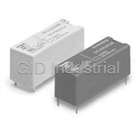
Power Relay 19VDC 8A SPST-NO(28.5x10.1x12.3)mm THT 1-1393224-1
Request a Quote

The quote request has been received
Close

Facing challenges or have inquiries? Feel free to contact us!
Call Us +1-469-283-2440
What they say about us
FANTASTIC RESOURCE
One of our top priorities is maintaining our business with precision, and we are constantly looking for affiliates that can help us achieve our goal. With the aid of GID Industrial, our obsolete product management has never been more efficient. They have been a great resource to our company, and have quickly become a go-to supplier on our list!
Bucher Emhart Glass
EXCELLENT SERVICE
With our strict fundamentals and high expectations, we were surprised when we came across GID Industrial and their competitive pricing. When we approached them with our issue, they were incredibly confident in being able to provide us with a seamless solution at the best price for us. GID Industrial quickly understood our needs and provided us with excellent service, as well as fully tested product to ensure what we received would be the right fit for our company.
Fuji
HARD TO FIND A BETTER PROVIDER
Our company provides services to aid in the manufacture of technological products, such as semiconductors and flat panel displays, and often searching for distributors of obsolete product we require can waste time and money. Finding GID Industrial proved to be a great asset to our company, with cost effective solutions and superior knowledge on all of their materials, it’d be hard to find a better provider of obsolete or hard to find products.
Applied Materials
CONSISTENTLY DELIVERS QUALITY SOLUTIONS
Over the years, the equipment used in our company becomes discontinued, but they’re still of great use to us and our customers. Once these products are no longer available through the manufacturer, finding a reliable, quick supplier is a necessity, and luckily for us, GID Industrial has provided the most trustworthy, quality solutions to our obsolete component needs.
Nidec Vamco
TERRIFIC RESOURCE
This company has been a terrific help to us (I work for Trican Well Service) in sourcing the Micron Ram Memory we needed for our Siemens computers. Great service! And great pricing! I know when the product is shipping and when it will arrive, all the way through the ordering process.
Trican Well Service
GO TO SOURCE
When I can't find an obsolete part, I first call GID and they'll come up with my parts every time. Great customer service and follow up as well. Scott emails me from time to time to touch base and see if we're having trouble finding something.....which is often with our 25 yr old equipment.
ConAgra Foods