

 Manufacturers
TE CONNECTIVITY 1617025-6
Description
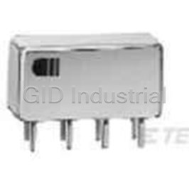
Electromechanical Relay 26.5VDC 700Ohm 2A DPDT(33.53x10.41x10.41)mm Flange Commercial and Industrial Relay
1617025-6
Part Number
1617025-6
Price
Request Quote
Manufacturer
TE CONNECTIVITY
Lead Time
Request Quote
Category
Relays and I/O Modules » Relay Other
Specifications
Manufacturer
TE Connectivity
Manufacturers Part #
1617025-6
Industry Aliases
HFC1230K00
Sub-Category
Other Relays
Brand
Raychem Wire and Tubing
Factory Pack Quantity
1
Datasheet
DDEController?Action=srchrtrv&DocNm=5-1773450-5_Section1&DocType=CS&DocLang=English&s_cid=1046.pdf
5355 KiB

Extracted Text
CII Low Signal Relays CII Low Signal Relays Table of Contents Single Pole, Electrically Held, 1 Amp and Less . . . . . . . . . . . . . . . . . . . . . . . . . . . . .1-2 – 1-9 1MA, 1MAD, 1MADD . . . . . . . . . . . . . . . . . . . . . . . . . . . . . . . . . . . . . . . . . . . . . . . .1-2, 1-3 1MS, 1MSD, 1MSDD . . . . . . . . . . . . . . . . . . . . . . . . . . . . . . . . . . . . . . . . . . . . . . . .1-4, 1-5 1 1MAT . . . . . . . . . . . . . . . . . . . . . . . . . . . . . . . . . . . . . . . . . . . . . . . . . . . . . . . . . . . .1-6, 1-7 1MST . . . . . . . . . . . . . . . . . . . . . . . . . . . . . . . . . . . . . . . . . . . . . . . . . . . . . . . . . . . .1-8, 1-9 Double Pole, Electrically Held, 1 Amp and Less . . . . . . . . . . . . . . . . . . . . . . . . . .1-10 – 1-35 MA, MAD, MADD . . . . . . . . . . . . . . . . . . . . . . . . . . . . . . . . . . . . . . . . . . . . . . . . .1-10, 1-11 MS, MSD, MSDD . . . . . . . . . . . . . . . . . . . . . . . . . . . . . . . . . . . . . . . . . . . . . . . . .1-12, 1-13 HM, HMD, HS, HSD . . . . . . . . . . . . . . . . . . . . . . . . . . . . . . . . . . . . . . . . . . . . . . .1-14, 1-15 MGA, MGAD, MGADD . . . . . . . . . . . . . . . . . . . . . . . . . . . . . . . . . . . . . . . . . . . . .1-16, 1-17 MGS, MGSD, MGSDD . . . . . . . . . . . . . . . . . . . . . . . . . . . . . . . . . . . . . . . . . . . . .1-18, 1-19 HC, HCD, HCS, HCSD . . . . . . . . . . . . . . . . . . . . . . . . . . . . . . . . . . . . . . . . . . . . .1-20, 1-21 MAT . . . . . . . . . . . . . . . . . . . . . . . . . . . . . . . . . . . . . . . . . . . . . . . . . . . . . . . . . . .1-22, 1-23 MST . . . . . . . . . . . . . . . . . . . . . . . . . . . . . . . . . . . . . . . . . . . . . . . . . . . . . . . . . . .1-24, 1-25 MGAT . . . . . . . . . . . . . . . . . . . . . . . . . . . . . . . . . . . . . . . . . . . . . . . . . . . . . . . . . .1-26, 1-27 MGST . . . . . . . . . . . . . . . . . . . . . . . . . . . . . . . . . . . . . . . . . . . . . . . . . . . . . . . . . .1-28, 1-29 SMGA, SMGAD, SMGADD . . . . . . . . . . . . . . . . . . . . . . . . . . . . . . . . . . . . . . . . .1-30, 1-31 SMGS, SMGSD, SMGSDD . . . . . . . . . . . . . . . . . . . . . . . . . . . . . . . . . . . . . . . . .1-32, 1-33 SHC, SHCD, SHCS, SHCSD . . . . . . . . . . . . . . . . . . . . . . . . . . . . . . . . . . . . . . . .1-34, 1-35 Double Pole, Electrically Held, 2 Amps and Less . . . . . . . . . . . . . . . . . . . . . . . . .1-36 – 1-46 HFW, HMB, HMS . . . . . . . . . . . . . . . . . . . . . . . . . . . . . . . . . . . . . . . . . . . . . . . . .1-36, 1-37 3SCV . . . . . . . . . . . . . . . . . . . . . . . . . . . . . . . . . . . . . . . . . . . . . . . . . . . . . . . . . .1-38, 1-39 HFC . . . . . . . . . . . . . . . . . . . . . . . . . . . . . . . . . . . . . . . . . . . . . . . . . . . . . . . . . . . . . . . .1-40 3SBC . . . . . . . . . . . . . . . . . . . . . . . . . . . . . . . . . . . . . . . . . . . . . . . . . . . . . . . . . .1-41, 1-42 3SCC . . . . . . . . . . . . . . . . . . . . . . . . . . . . . . . . . . . . . . . . . . . . . . . . . . . . . . . . . .1-43, 1-44 3SAC, 3SAE . . . . . . . . . . . . . . . . . . . . . . . . . . . . . . . . . . . . . . . . . . . . . . . . . . . . .1-45, 1-46 Double Pole, Magnetic Latching, 2 Amps and Less . . . . . . . . . . . . . . . . . . . . . . .1-47 – 1-52 LS . . . . . . . . . . . . . . . . . . . . . . . . . . . . . . . . . . . . . . . . . . . . . . . . . . . . . . . . . . . . .1-47, 1-48 3SDM . . . . . . . . . . . . . . . . . . . . . . . . . . . . . . . . . . . . . . . . . . . . . . . . . . . . . . . . . .1-49, 1-50 3SAM . . . . . . . . . . . . . . . . . . . . . . . . . . . . . . . . . . . . . . . . . . . . . . . . . . . . . . . . . .1-51, 1-52 Four Pole, Electrically Held, 2 Amps and Less . . . . . . . . . . . . . . . . . . . . . . . . . . .1-53 – 1-59 SR . . . . . . . . . . . . . . . . . . . . . . . . . . . . . . . . . . . . . . . . . . . . . . . . . . . . . . . . . . . .1-53, 1-54 3SBH . . . . . . . . . . . . . . . . . . . . . . . . . . . . . . . . . . . . . . . . . . . . . . . . . . . . . . . . .1-55 – 1-57 3SDH . . . . . . . . . . . . . . . . . . . . . . . . . . . . . . . . . . . . . . . . . . . . . . . . . . . . . . . . . .1-58, 1-59 Four Pole, Magnetic Latching, 2 Amps and Less . . . . . . . . . . . . . . . . . . . . . . . . . .1-60 – 1-62 3SBM . . . . . . . . . . . . . . . . . . . . . . . . . . . . . . . . . . . . . . . . . . . . . . . . . . . . . . . . .1-60 – 1-62 Six Pole, Electrically Held, 2 Amps and Less . . . . . . . . . . . . . . . . . . . . . . . . . . . . .1-63, 1-64 SS . . . . . . . . . . . . . . . . . . . . . . . . . . . . . . . . . . . . . . . . . . . . . . . . . . . . . . . . . . . .1-63, 1-64 Double Pole, Electrically Held, 5 Amps and Less . . . . . . . . . . . . . . . . . . . . . . . . .1-65 – 1-69 HFW4A, HFW5A . . . . . . . . . . . . . . . . . . . . . . . . . . . . . . . . . . . . . . . . . . . . . . . . .1-65, 1-66 HFC4A, HFC5A . . . . . . . . . . . . . . . . . . . . . . . . . . . . . . . . . . . . . . . . . . . . . . . . . . . . . . .1-67 FW, FW5A, SF, SF5A . . . . . . . . . . . . . . . . . . . . . . . . . . . . . . . . . . . . . . . . . . . . . .1-68, 1-69 Single Pole, Electrically Held, 10 Amps and Less . . . . . . . . . . . . . . . . . . . . . . . . . . . . . . .1-70 C . . . . . . . . . . . . . . . . . . . . . . . . . . . . . . . . . . . . . . . . . . . . . . . . . . . . . . . . . . . . . . . . . .1-70 Double Pole, Electrically Held, 10 Amps and Less . . . . . . . . . . . . . . . . . . . . . . . . .1-71, 1-72 07 . . . . . . . . . . . . . . . . . . . . . . . . . . . . . . . . . . . . . . . . . . . . . . . . . . . . . . . . . . . . .1-71, 1-72 1-1 Catalog 5-1773450-5 Dimensions are shown for Dimensions are in millimeters USA: +1 800 522 6752 For additional support numbers Revised 3-13 reference purposes only. unless otherwise specified. Asia Pacific: +86 0 400 820 6015 please visit www.te.com Specifications subject UK: +44 800 267 666 www.te.com to change. CII Low Signal Relays Single Pole, Electrically Held, 1 Amp and Less 1MA, 1MAD, 1MADD 1MA 1MAD 1MADD Standard TO-5 Standard TO-5 Standard TO-5 Diode High Performance Relay Diode Suppressed Suppressed/Protected High Performance Relay High Performance Relay Qualified to MIL-R-39016/7 Qualified to Qualified to MIL-R-39016/23 MIL-R-39016/24 A2 X1 A2 X1 A2 X1 + + X2 X2 X2 – – A1 A3 A1 A3 A1 A3 Terminal View Terminal View Terminal View Product Facts Product Facts Product Facts n Hermetically sealed n Suppression diode n Suppression & protection diodes n High shock & vibration n Hermetically sealed ratings n Hermetically sealed n High shock & vibration n Spreader pad ratings n High shock & vibration ratings n Excellent RF switching n Spreader pad n Spreader pad n Excellent RF switching n Excellent RF switching Electrical Characteristics Contact Ratings Contact Arrangement — Contact Operations Type Load MINd. 1 Form C (SPDT) 1.0 A @ 28 Vdc Resistive 100,000 Contact Material — 250 mA @ 115 Vac, 60 Hz & 400 Hz Resistive (case not grounded) 100,000 Stationary — Gold/platinum/palladium/silver alloy 100 mA @ 115 Vac, 60 Hz & 400 Hz Resistive 100,000 (gold plated) 0.2 A @ 28 Vdc Inductive (0.32 Henry) 100,000 Moveable — 0.1 A @ 28 Vdc Lamp 100,000 Gold/platinum/palladium/silver alloy 30 μA @ 50 mVdc Low Level 1,000,000 (gold plated) 0.1 A @ 28 Vdc Intermediate Current 50,000 Contact Resistance — Before Life — 100 milliohms max. (measured @ 10 mA @ 6 Vdc) After Life — 200 milliohms max. (measured @ 1 A @ 28 Vdc) Mechanical Life Expectancy — .335 (8.51) DIA MAX 1 million operations Coil Voltage — 5 to 26.5 Vdc .370 (9.40) DIA MAX . .280 (7.11) Coil Power — 512 mW max. @ 25°C MAX .031 ± .003 (0.79) ± .035 ± .010 Duty Cycle — Continuous (0.89) Pick-up Voltage — Approximately 50% of nominal coil voltage TERMINALS Pick-up Sensitivity — W 1.500 MINd (38.1) C .500 MINd (12.7) 100 mW max. @ 25°C P .187 ± .010 (4.75 ± .25) (Length excludes spreader pad) .200 (5.08) DIA ± 3° 45° ± 3 ° +.002 .017 (0.43) DIA -.001 .370 (9.40) DIA MAX 1MA/1MAD/1MADD Header 1MA/1MAD/1MADD Enclosure 1-2 Catalog 5-1773450-5 Dimensions are shown for Dimensions are in millimeters USA: +1 800 522 6752 For additional support numbers Revised 3-13 reference purposes only. unless otherwise specified. Asia Pacific: +86 0 400 820 6015 please visit www.te.com Specifications subject UK: +44 800 267 666 www.te.com to change. CII Low Signal Relays CII Low Signal Relays Single Pole, Electrically Held, 1 Amp and Less (Continued) Operating Characteristics Environmental Characteristics Semiconductor Characteristics 1MA, 1MAD, 1MADD Timing — Temperature Range — Diode — (Continued) Operate Time — 2.0 ms max. -65°C to +125°C 100 Vdc peak inverse voltage (PIV) 1 Release Time — 1.0 Vdc max. transient voltage Weight — 1MA — 2.0 ms max. 0.08 oz. (2.27 grms) 1MAD/1MADD — 4.0 ms max. 0.09 oz. (2.52 grms) with spreader pad (suppression diode, suppression/ attached steering diodes) Vibration Resistance — Contact Bounce — 1.5 ms max 30 G’s, 10 to 3,000 Hz Dielectric Withstanding Voltage — Shock Resistance — Between Open Contacts — 75 G’s, 6 ±1 ms max. 500 Vrms 60 Hz QPL Approval — Between Adjacent Contacts — MIL-R-39016/7 (J1MA) 500 Vrms 60 Hz MIL-R-39016/23 (J1MAD) Between Contacts & Coil — MIL-R-39016/24 (J1MADD) 500 Vrms 60 Hz Insulation Resistance — 10,000 megohms @ 500 Vdc 1,000 megohms @ 500 Vdc (coil to case @ +125°C) .103 (2.62) .014 ± .003 (0.36) 0.47 (1.19) DIA .370 (9.40) SQ MAX .100 (2.54) .100 (2.54) .140 – .175 DIA SW (3.56 – 4.45) Spreader & Mounting Pads Coil Data Coil Pickup Pickup Drop-Out Drop-Out Nom. Coil Circuit Coil Circuit Base Turn Base Turn Nom. Coil Resistance Voltage Voltage Voltage Voltage Max. Coil Current Current On Current On Current Power Coil in Ohms Vdc (Max.) Vdc (Max.) Vdc (Min.) Vdc (Min.) Coil Voltage mA (Max.) mA (Min.) mA (Max.) mA (Max.) (mW) Desig. ±10% @ 25°C @ 25°C @ 125°C @ 25°C @ -65°C Voltage (Vdc) (Note 1&2) (Note 1&2) @ 25°C @ 125°C @ 25°C (Note 1) (Note 2) (Note 2) (Note 2) (Note 2) 1MA/1MAD 5.0 63 n/a n/a 2.8 n/a 3.7 n/a 0.23 0.15 397 6.0 5 6.0 125 n/a n/a 3.5 n/a 4.5 n/a 0.28 0.18 288 8.0 6 9.0 280 n/a n/a 5.3 n/a 6.8 n/a 0.54 0.35 289 12.0 9 12.0 500 n/a n/a 7.0 n/a 9.0 n/a 0.63 0.40 288 16.0 12 18.0 1,130 n/a n/a 10.5 n/a 13.5 n/a 0.91 0.58 287 24.0 18 26.5 2,000 n/a n/a 14.2 n/a 18.0 n/a 1.37 0.89 351 32.0 26 1MADD 5.0 50 100.0 72.7 3.5 n/a 4.5 n/a 0.23 0.15 500 6.0 5 6.0 98 62.4 46.3 4.1 n/a 5.5 n/a 0.28 0.18 367 8.0 6 9.0 280 33.7 25.9 6.3 n/a 7.8 n/a 0.54 0.35 289 12.0 9 12.0 500 25.6 20.0 8.0 n/a 10.0 n/a 0.63 0.40 288 16.0 12 18.0 1,130 17.2 13.6 11.6 n/a 14.5 n/a 0.91 0.58 287 24.0 18 26.5 2,000 14.4 11.5 15.4 n/a 19.0 n/a 1.37 0.89 351 32.0 26 Notes: 1. Coil resistance not directly measurable. Coil current should be within limits shown when tested at nominal voltage at 25°C for 5 seconds max. 2. Set base current at 3 mA to 15 mA during measurements. Ordering Instructions Catalog-selected Relays: The catalog number is derived by choosing the proper CODE for each of the relay characteristics in the order in which the codes are listed. Specifying a Part Number Example*: Type Terminal Diodes Coils Spreader/Mounting Pads 1MA CD -26 S * The part number example shown on this page is for catalog items. For a list of specific QPL part numbers, please see the index in Section 15. 1-3 Catalog 5-1773450-5 Dimensions are shown for Dimensions are in millimeters USA: +1 800 522 6752 For additional support numbers Revised 3-13 reference purposes only. unless otherwise specified. Asia Pacific: +86 0 400 820 6015 please visit www.te.com Specifications subject UK: +44 800 267 666 www.te.com to change. CII Low Signal Relays Single Pole, Electrically Held, 1 Amp and Less (Continued) 1MS, 1MSD, 1MSDD 1MS 1MSD 1MSDD Sensitive TO-5 Sensitive TO-5 Sensitive TO-5 Diode High Performance Relay Diode Suppressed Suppressed/Protected High Performance Relay High Performance Relay Qualified to MIL-R-39016/10 Qualified to Qualified to MIL-R-39016/25 MIL-R-39016/26 A2 X1 A2 X1 A2 X1 + + X2 X2 X2 – – A1 A3 A1 A3 A1 A3 Terminal View Terminal View Terminal View Product Facts Product Facts Product Facts n Hermetically sealed n Suppression diode n Suppression & protection diodes n High shock & vibration n Hermetically sealed ratings n Hermetically sealed n High shock & vibration n Spreader pad ratings n High shock & vibration ratings n Excellent RF switching n Spreader pad n Spreader pad n Excellent RF switching n Excellent RF switching Electrical Characteristics Contact Ratings Contact Arrangement — Contact Operations Type Load MINd. 1 Form C (SPDT) 1.0 A @ 28 Vdc Resistive 100,000 Contact Material — 250 mA @ 115 Vac, 60 Hz & 400 Hz Resistive (case not grounded) 100,000 Stationary — Gold/platinum/palladium/silver alloy 100 mA @ 115 Vac, 60 Hz & 400 Hz Resistive 100,000 (gold plated) 0.2 A @ 28 Vdc Inductive (0.32 Henry) 100,000 Moveable — 0.1 A @ 28 Vdc Lamp 100,000 Gold/platinum/palladium/silver alloy 30 μA @ 50 mVdc Low Level 1,000,000 (gold plated) 0.1 A @ 28 Vdc Intermediate Current 50,000 Contact Resistance — Before Life — 100 milliohms max. (measured @ 10 mA @ 6 Vdc) After Life — 200 milliohms max. (measured @ 1 A @ 28 Vdc) Mechanical Life Expectancy — .335 (8.51) DIA MAX 1 million operations .370 (9.40) DIA MAX . Coil Voltage — 5 to 40 Vdc ± ± .031 .003 (0.79) Coil Power — 506 mW max. @ 25°C .035 ± .010 .375 (9.53) (0.89) Duty Cycle — Continuous MAX Pick-up Voltage — Approximately 50% of nominal coil voltage Pick-up Sensitivity — TERMINALS W 1.500 MINd (38.1) 40 mW max. @ 25°C C .500 MINd (12.7) .200 (5.08) P .187±.010 (4.75±.25) DIA ± 3 ° (Length excludes spreader pad) ± 45° 3° 1MS/1MSD/1MSDD Header .017+ . 0 0 2 (0.43) DIA -.001 .370 (9.40) DIA MAX 1MS/1MSD/1MSDD Enclosure 1-4 Catalog 5-1773450-5 Dimensions are shown for Dimensions are in millimeters USA: +1 800 522 6752 For additional support numbers Revised 3-13 reference purposes only. unless otherwise specified. Asia Pacific: +86 0 400 820 6015 please visit www.te.com Specifications subject UK: +44 800 267 666 www.te.com to change. CII Low Signal Relays CII Low Signal Relays Single Pole, Electrically Held, 1 Amp and Less (Continued) Operating Characteristics Environmental Characteristics Semiconductor Characteristics 1MS, 1MSD, 1MSDD Timing — Temperature Range — Diode — (Continued) Operate Time — 4.0 ms max. -65°C to +125°C 100 Vdc peak inverse voltage (PIV) 1 Release Time — 1.0 Vdc max. transient voltage Weight — 1MS — 2.5 ms max. 0.10 oz. (2.84 grms) 1MSD/1MSDD — 7.5 ms max. 0.11 oz. (3.09 grms) with spreader pad (suppression diode, suppression/ attached steering diodes) Vibration Resistance — Contact Bounce — 1.5 ms max 30 G’s, 10 to 3,000 Hz Dielectric Withstanding Voltage — Shock Resistance — Between Open Contacts — 75 G’s, 6 ±1 ms max. 500 Vrms 60 Hz QPL Approval — Between Adjacent Contacts — MIL-R-39016/10 (J1MS) 500 Vrms 60 Hz MIL-R-39016/25 (J1MSD) Between Contacts & Coil — MIL-R-39016/26 (J1MSDD) 500 Vrms 60 Hz Insulation Resistance — 10,000 megohms @ 500 Vdc 1,000 megohms @ 500 Vdc .103 (2.62) (coil to case @ +125°C) .014 ± .003 (0.36) 0.47 (1.19) DIA .370 (9.40) SQ MAX .100 (2.54) .100 (2.54) SW .140 – .175 DIA (3.56 – 4.45) Spreader & Mounting Pads Coil Data Coil Pickup Pickup Drop-Out Drop-Out Nom. Coil Circuit Coil Circuit Base Turn Base Turn Nom. Coil Resistance Voltage Voltage Voltage Voltage Max. Coil Current Current On Current On Current Power Coil in Ohms Vdc (Max.) Vdc (Max.) Vdc (MINd.) Vdc (MINd.) Coil Voltage mA (Max.) mA (MINd.) mA (Max.) mA (Max.) (mW) Desig. ±10% @ 25°C @ 25°C @ 125°C @ 25°C @ -65°C Voltage (Vdc) (Note 1&2) (Note 1&2) @ 25°C @ 125°C @ 25°C (Note 1) (Note 2) (Note 2) (Note 2) (Note 2) 1MS/1MSD 5.0 125 n/a n/a 2.8 n/a 3.7 n/a 0.23 0.15 200 8.0 5 6.0 255 n/a n/a 3.5 n/a 4.5 n/a 0.28 0.18 141 11.0 6 9.0 630 n/a n/a 5.3 n/a 6.8 n/a 0.54 0.35 129 12.0 9 12.0 1,025 n/a n/a 7.0 n/a 9.0 n/a 0.63 0.40 140 22.0 12 18.0 2,300 n/a n/a 10.5 n/a 13.5 n/a 0.91 0.59 141 24.0 18 26.5 4,000 n/a n/a 14.2 n/a 18.0 n/a 1.37 0.89 176 45.0 26 32.0 6,500 n/a n/a 18.7 n/a 24.0 n/a 1.59 1.0 158 57.0 32 40.0 11,000 n/a n/a 23.3 n/a 30.0 n/a 2.0 1.3 145 75.0 40 1MSDD 5.0 100 50.0 36.3 3.5 n/a 4.5 n/a 0.23 0.15 250 8.0 5 6.0 200 30.6 22.7 4.1 n/a 5.5 n/a 0.28 0.18 180 11.0 6 9.0 630 15.0 11.5 6.3 n/a 7.8 n/a 0.54 0.35 129 16.0 9 12.0 1,025 12.5 9.7 8.0 n/a 10.0 n/a 0.63 0.40 140 22.0 12 18.0 2,300 8.5 6.7 11.6 n/a 14.5 n/a 0.91 0.58 141 33.0 18 26.5 4,000 7.2 5.7 15.4 n/a 19.0 n/a 1.37 0.89 176 45.0 26 32.0 6,500 5.4 4.3 17.0 n/a 21.0 n/a 1.5 0.95 158 57.0 32 40.0 11,000 4.0 3.2 22.0 n/a 27.0 n/a 2.0 1.28 145 75.0 40 Notes: 1. Coil resistance not directly measurable. Coil current should be within limits shown when tested at nominal voltage at 25°C for 5 seconds max. 2. Set base current at 3 mA to 15 mA during measurements. Ordering Instructions Catalog-selected Relays: The catalog number is derived by choosing the proper CODE for each of the relay characteristics in the order in which the codes are listed. Specifying a Part Number Example: Type Terminal Diodes Coils Spreader/Mounting Pads 1MS CD -26 S * The part number example shown on this page is for catalog items. For a list of specific QPL part numbers, please see the index in Section 15. 1-5 Catalog 5-1773450-5 Dimensions are shown for Dimensions are in millimeters USA: +1 800 522 6752 For additional support numbers Revised 3-13 reference purposes only. unless otherwise specified. Asia Pacific: +86 0 400 820 6015 please visit www.te.com Specifications subject UK: +44 800 267 666 www.te.com to change. CII Low Signal Relays Single Pole, Electrically Held, 1 Amp and Less (Continued) 1MAT 1MAT Standard TO-5 Diode Suppressed/ Transistor Driven High Performance Relay Qualified to MIL-R-28776/5 + X1 A2 XB – A1 X2 A3 XC Terminal View Product Facts n Transistor driver & suppression diode n Hermetically sealed n High shock & vibration ratings n Spreader pad n Excellent RF switching Electrical Characteristics Contact Ratings Contact Arrangement — Contact Operations Type Load MINd. 1 Form C (SPDT) 1.0 A @ 28 Vdc Resistive 100,000 Contact Material — 250 mA @ 115 Vac, 60 Hz & 400 Hz Resistive (case not grounded) 100,000 Stationary — Gold/platinum/palladium/silver alloy 100 mA @ 115 Vac, 60 Hz & 400 Hz Resistive 100,000 (gold plated) 0.2 A @ 28 Vdc Inductive (0.32 Henry) 100,000 Moveable — 0.1 A @ 28 Vdc Lamp 100,000 Gold/platinum/palladium/silver alloy 30 μA @ 50 mVdc Low Level 1,000,000 (gold plated) 0.1 A @ 28 Vdc Intermediate Current 50,000 Contact Resistance — Before Life — 100 milliohms max. (measured @ 10 mA @ 6 Vdc) After Life — 200 milliohms max. .335 (8.51) DIA MAX (measured @ 1 A @ 28 Vdc) Mechanical Life Expectancy — 1 million operations .280 (7.11) .370 (9.40) DIA MAX MAX Coil Voltage — 5 to 26.5 Vdc ± .031 ± .003 (0.79) . .035 ± .010 Coil Power — 512 mW max. @ 25°C (0.89) Duty Cycle — Continuous TERMINALS Pick-up Voltage — Approximately W 1.500 MINd (38.1) C .500 MINd (12.7) 50% of nominal coil voltage P .187 ± .010 (4.75 ± .25) Pick-up Sensitivity — (Length excludes spreader pad) 100 mW max. @ 25°C .200 (5.08) ± 36° 3° DIA .017+ . 0 0 2 (0.43) DIA ± 3 ° -.001 .370 (9.40) DIA MAX 1MAT Header 1MAT Enclosure 1-6 Catalog 5-1773450-5 Dimensions are shown for Dimensions are in millimeters USA: +1 800 522 6752 For additional support numbers Revised 3-13 reference purposes only. unless otherwise specified. Asia Pacific: +86 0 400 820 6015 please visit www.te.com Specifications subject UK: +44 800 267 666 www.te.com to change. CII Low Signal Relays CII Low Signal Relays Single Pole, Electrically Held, 1 Amp and Less (Continued) Operating Characteristics Environmental Characteristics Semiconductor Characteristics 1MAT (Continued) Timing — Temperature Range — Diode — Operate Time — 2.0 ms max. -65°C to +125°C 100 Vdc peak inverse voltage (PIV) 1 Release Time — 1.0 Vdc max. transient voltage Weight — 4.0 ms max. 0.08 oz. (2.27 grms) Transistor — Contact Bounce — 1.5 ms max 0.09 oz. (2.52 grms) with spreader pad 0.3 Vdc MINd. base turn off voltage; attached 6.0 Vdc min. emitter-base breakdown Dielectric Withstanding Voltage — voltage (BV ) @ 25°C; Between Open Contacts — Vibration Resistance — EBO 80.0 Vdc min. collector-base breakdown 500 Vrms 60 Hz 30 G’s, 10 to 3,000 Hz voltage (BV ) @ 25°C & I =100 μA Between Adjacent Contacts — CBO C Shock Resistance — 500 Vrms 60 Hz 75 G’s, 6 ±1 ms max. Between Contacts & Coil — QPL Approval — 500 Vrms 60 Hz MIL-R-28776/5 (J1MAT) Insulation Resistance — 10,000 megohms @ 500 Vdc 1,000 megohms @ 500 Vdc (coil to case @ +125°C) .103 (2.62) .014 ± .003 (0.36) 0.47 (1.19) DIA .370 (9.40) SQ MAX .100 (2.54) .100 (2.54) .140 – .175 DIA SW (3.56 – 4.45) Spreader & Mounting Pads Coil Data Coil Pickup Pickup Drop-Out Drop-Out Nom. Coil Circuit Coil Circuit Base Turn Base Turn Nom. Coil Resistance Voltage Voltage Voltage Voltage Max. Coil Current Current On Current On Current Power Coil in Ohms Vdc (Max.) Vdc (Max.) Vdc (MINd.) Vdc (MINd.) Coil Voltage mA (Max.) mA (MINd.) mA (Max.) mA (Max.) (mW) Desig. ±10% @ 25°C @ 25°C @ 125°C @ 25°C @ -65°C Voltage (Vdc) (Note 1&2) (Note 1&2) @ 25°C @ 125°C @ 25°C (Note 1) (Note 2) (Note 2) (Note 2) (Note 2) 1MAT 5.0 63 89.6 66.6 3.0 0.60 3.9 2.38 0.24 0.15 397 5.8 5 6.0 125 55.5 42.0 3.8 0.42 5.2 1.60 0.31 0.18 288 8.0 6 9.0 280 38.1 28.0 5.6 0.27 7.8 1.07 0.47 0.35 289 12.0 9 12.0 500 28.1 20.9 7.2 0.21 10.0 0.80 0.62 0.40 288 16.0 12 18.0 1,130 18.8 13.8 10.7 0.12 14.5 0.53 0.94 0.58 287 24.0 18 26.5 2,000 15.5 11.5 14.4 0.10 19.0 0.40 1.25 0.89 351 32.0 26 Notes: 1. Coil resistance not directly measurable. Coil current should be within limits shown when tested at nominal voltage at 25°C for 5 seconds max. 2. Set base current at 3 mA to 15 mA during measurements. Ordering Instructions Catalog-selected Relays: The catalog number is derived by choosing the proper CODE for each of the relay characteristics in the order in which the codes are listed. Specifying a Part Number Example: Type Terminal Diodes Coils Spreader/Mounting Pads 1MA CT -26 S * The part number example shown on this page is for catalog items. For a list of specific QPL part numbers, please see the index in Section 15. 1-7 Catalog 5-1773450-5 Dimensions are shown for Dimensions are in millimeters USA: +1 800 522 6752 For additional support numbers Revised 3-13 reference purposes only. unless otherwise specified. Asia Pacific: +86 0 400 820 6015 please visit www.te.com Specifications subject UK: +44 800 267 666 www.te.com to change. CII Low Signal Relays Single Pole, Electrically Held, 1 Amp and Less (Continued) 1MST 1MST Sensitive TO-5 Diode Suppressed/ Transistor Driven High Performance Relay Qualified to MIL-R-28776/4 + X1 A2 XB – A1 X2 A3 XC Terminal View Product Facts n Transistor driver & suppression diode n Hermetically sealed n High shock & vibration ratings n Spreader pad n Excellent RF switching Electrical Characteristics Contact Ratings Contact Arrangement — Contact Operations Type Load Min. 1 Form C (SPDT) 1.0 A @ 28 Vdc Resistive 100,000 Contact Material — 250 mA @ 115 Vac, 60 Hz & 400 Hz Resistive (case not grounded) 100,000 Stationary — Gold/platinum/palladium/silver alloy 100 mA @ 115 Vac, 60 Hz & 400 Hz Resistive 100,000 (gold plated) 0.2 A @ 28 Vdc Inductive (0.32 Henry) 100,000 Moveable — 0.1 A @ 28 Vdc Lamp 100,000 Gold/platinum/palladium/silver alloy 30 μA @ 50 mVdc Low Level 1,000,000 (gold plated) 0.1 A @ 28 Vdc Intermediate Current 50,000 Contact Resistance — Before Life — 100 milliohms max. (measured @ 10 mA @ 6 Vdc) After Life — 200 milliohms max. .335 (8.51) DIA MAX (measured @ 1 A @ 28 Vdc) Mechanical Life Expectancy — 1 million operations .370 (9.40) DIA MAX .375 (9.53) Coil Voltage — 5 to 40 Vdc ± ± .031 .003 (0.79) . .035 ± .010 MAX (0.89) Coil Power — 506 mW max. @ 25°C Duty Cycle — Continuous Pick-up Voltage — Approximately TERMINALS 50% of nominal coil voltage W 1.500 MIN (38.1) C .500 MIN (12.7) Pick-up Sensitivity — P .187±.010 (4.75±.25) 40 mW max. @ 25°C (Length excludes spreader pad) .200 (5.08) 36° ± 3 ° DIA ± 3° 1MST Header .017+ . 0 0 2 (0.43) DIA -.001 .370 (9.40) DIA MAX 1MST Enclosure 1-8 Catalog 5-1773450-5 Dimensions are shown for Dimensions are in millimeters USA: +1 800 522 6752 For additional support numbers Revised 3-13 reference purposes only. unless otherwise specified. Asia Pacific: +86 0 400 820 6015 please visit www.te.com Specifications subject UK: +44 800 267 666 www.te.com to change. CII Low Signal Relays CII Low Signal Relays Single Pole, Electrically Held, 1 Amp and Less (Continued) Operating Characteristics Environmental Characteristics Semiconductor Characteristics 1MST (Continued) Timing — Temperature Range — Diode — Operate Time — -65°C to +125°C 100 Vdc peak inverse voltage (PIV) 1 3.5 ms max. 1.0 Vdc max. transient voltage Weight — Release Time — 0.10 oz. (2.84 grms) Transistor — 7.5 ms max. 0.11 oz. (3.09 grms) with spreader pad 0.3 Vdc min. base turn off voltage; Contact Bounce — 1.5 ms max attached 6.0 Vdc min. emitter-base breakdown voltage (BV ) @ 25°C; Dielectric Withstanding Voltage — Vibration Resistance — EBO 80.0 Vdc min. collector-base breakdown Between Open Contacts — 30 G’s, 10 to 3,000 Hz voltage (BV ) @ 25°C & I =100 μA 500 Vrms 60 Hz CBO C Shock Resistance — Between Adjacent Contacts — 75 G’s, 6 ±1 ms max. 500 Vrms 60 Hz QPL Approval — Between Contacts & Coil — MIL-R-28776/4 (J1MST) 500 Vrms 60 Hz Insulation Resistance — 10,000 megohms @ 500 Vdc 1,000 megohms @ 500 Vdc (coil to case @ +125°C) .103 (2.62) .014 ± .003 (0.36) .370 (9.40) SQ MAX 0.47 (1.19) DIA .100 (2.54) .100 (2.54) SW .140 – .175 DIA (3.56 – 4.45) Spreader & Mounting Pads Coil Data Coil Pickup Pickup Drop-Out Drop-Out Nom. Coil Circuit Coil Circuit Base Turn Base Turn Nom. Coil Resistance Voltage Voltage Voltage Voltage Max. Coil Current Current On Current On Current Power Coil in Ohms Vdc (Max.) Vdc (Max.) Vdc (Min.) Vdc (Min.) Coil Voltage mA (Max.) mA (Min.) mA (Max.) mA (Max.) (mW) Desig. ±10% @ 25°C @ 25°C @ 125°C @ 25°C @ -65°C Voltage (Vdc) (Note 1&2) (Note 1&2) @ 25°C @ 125°C @ 25°C (Note 1) (Note 2) (Note 2) (Note 2) (Note 2) 1MST 5.0 125 47.8 34.7 2.6 0.28 3.6 1.20 0.22 0.15 200 8.0 5 6.0 255 27.7 21.2 3.5 0.20 4.8 0.78 0.28 0.18 141 11.0 6 9.0 630 16.8 11.8 5.4 0.13 7.8 0.48 0.54 0.35 129 16.0 9 12.0 1,025 13.6 10.1 6.6 0.10 10.0 0.39 0.63 0.41 140 22.0 12 18.0 2,300 9.1 6.7 9.8 0.07 14.5 0.26 0.91 0.58 141 33.0 18 26.5 4,000 7.7 5.7 12.8 0.05 19.0 0.20 1.37 0.89 176 45.0 26 32.0 6,500 5.8 4.2 18.7 0.04 24.0 0.16 1.60 1.00 158 57.0 32 40.0 11,000 4.3 3.1 23.3 0.03 30.0 0.13 2.10 1.30 145 75.0 40 Notes: 1. Coil resistance not directly measurable. Coil current should be within limits shown when tested at nominal voltage at 25°C for 5 seconds max. 2. Set base current at 3 mA to 15 mA during measurements. Ordering Instructions Catalog-selected Relays: The catalog number is derived by choosing the proper CODE for each of the relay characteristics in the order in which the codes are listed. Specifying a Part Number Example: Type Terminal Diodes Coils Spreader/Mounting Pads 1MS CT -26 S * The part number example shown on this page is for catalog items. For a list of specific QPL part numbers, please see the index in Section 15. 1-9 Catalog 5-1773450-5 Dimensions are shown for Dimensions are in millimeters USA: +1 800 522 6752 For additional support numbers Revised 3-13 reference purposes only. unless otherwise specified. Asia Pacific: +86 0 400 820 6015 please visit www.te.com Specifications subject UK: +44 800 267 666 www.te.com to change. CII Low Signal Relays Double Pole, Electrically Held, 1 Amp and Less MA, MAD, MADD MA MAD MADD Standard TO-5 Standard TO-5 Standard TO-5 Diode High Performance Relay Diode Suppressed Suppressed/Protected High Performance Relay High Performance Relay Qualified to MIL-R-39016/9 Qualified to Qualified to MIL-R-39016/15 MIL-R-39016/20 – + – + X1 X2 X2 X1 X2 X1 A2 B2 A2 B2 A2 B2 A1 B1 A1 B1 A1 B1 A3 B3 A3 B3 A3 B3 Terminal View Terminal View Terminal View Product Facts Product Facts Product Facts n Hermetically sealed n Suppression diode n Suppression & protection diodes n High shock & vibration n Hermetically sealed ratings n Hermetically sealed n High shock & vibration n Spreader pads ratings n High shock & vibration ratings n Excellent RF switching n Spreader pads n Spreader pads n Excellent RF switching n Excellent RF switching Electrical Characteristics Contact Ratings Contact Arrangement — Contact Operations Type Load Min. 2 Form C (DPDT) 1.0 A @ 28 Vdc Resistive 100,000 Contact Material — 250 mA @ 115 Vac, 60 Hz & 400 Hz Resistive (case not grounded) 100,000 Stationary — Gold/platinum/palladium/silver alloy 100 mA @ 115 Vac, 60 Hz & 400 Hz Resistive 100,000 (gold plated) 0.2 A @ 28 Vdc Inductive (0.32 Henry) 100,000 Moveable — 0.1 A @ 28 Vdc Lamp 100,000 Gold/platinum/palladium/silver alloy 30 μA @ 50 mVdc Low Level 1,000,000 (gold plated) 0.1 A @ 28 Vdc Intermediate Current 50,000 Contact Resistance — Before Life — 100 milliohms max. (measured @ 10 mA @ 6 Vdc) After Life — 200 milliohms max. (measured @ 1 A @ 28 Vdc) .335 (8.51) DIA MAX Mechanical Life Expectancy — 1 million operations .370 (9.40) DIA MAX Coil Voltage — ± .280 (7.11) .031 .003 (0.79) 5 to 30 Vdc (MA/MAD) MAX .035 (0.89) 5 to 26.5 Vdc (MADD) Coil Power — 675 mW max. @ 25°C Duty Cycle — Continuous TERMINALS Pick-up Voltage — Approximately W 1.500 MIN (38.1) C .500 MIN (12.7) 50% of nominal coil voltage P .187±.010 (4.75±.25) Pick-up Sensitivity — (Length excludes mounting pad) .200 (5.08) 36° ± 3° 130 mW max. @ 25°C DIA GROUND PIN (OPTIONAL) Header OPTIONAL PINS .017 (0.43) DIA +.002 -.001 .370 (9.40) DIA MAX Enclosure 1-10 Catalog 5-1773450-5 Dimensions are shown for Dimensions are in millimeters USA: +1 800 522 6752 For additional support numbers Revised 3-13 reference purposes only. unless otherwise specified. Asia Pacific: +86 0 400 820 6015 please visit www.te.com Specifications subject UK: +44 800 267 666 www.te.com to change. CII Low Signal Relays CII Low Signal Relays Double Pole, Electrically Held, 1 Amp and Less (Continued) Operating Characteristics Environmental Characteristics Semiconductor Characteristics MA, MAD, MADD (Continued) Timing — Temperature Range — Diode — Operate Time — 2.0 ms max. -65°C to +125°C 100 Vdc peak inverse voltage (PIV) 1 Release Time — 1.0 Vdc max. transient voltage Weight — MA — 1.5 ms max. 0.09 oz. (2.55 grms) MAD/MADD — 4.0 ms max. 0.10 oz. (2.80 grms) with spreader pad (suppression diode, suppression/ attached steering diodes) Vibration Resistance — Contact Bounce — 1.5 ms max 30 G’s, 10 to 3,000 Hz Dielectric Withstanding Voltage — Shock Resistance — Between Open Contacts — 75 G’s, 6 ±1 ms max. 500 Vrms 60 Hz QPL Approval — Between Adjacent Contacts — MIL-R-39016/9 (JMA) 500 Vrms 60 Hz MIL-R-39016/15 (JMAD) Between Contacts & Coil — MIL-R-39016/20 (JMADD) 500 Vrms 60 Hz Insulation Resistance — 10,000 megohms min. @ 500 Vdc 1,000 megohms @ 500 Vdc (coil to case @ +125°C) .103 (2.62) .156 (3.96) .014± .003 (0.36) .370 (9.40) SQ MAX .395 (10.03) SQ MAX 0.47 (1.19) DIA .100 (2.54) .150 (3.81) .100 (2.54) .100 (2.54) .140 – .175 DIA (3.56 – 4.45) S S2 W Spreader & Mounting Pads Coil Data Coil Pickup Pickup Drop-Out Drop-Out Nom. Coil Circuit Coil Circuit Base Turn Base Turn Nom. Coil Resistance Voltage Voltage Voltage Voltage Max. Coil Current Current On Current On Current Power Coil in Ohms Vdc (Max.) Vdc (Max.) Vdc (Min.) Vdc (Min.) Coil Voltage mA (Max.) mA (Min.) mA (Max.) mA (Max.) (mW) Desig. ±10% @ 25°C @ 25°C @ 125°C @ 25°C @ -65°C Voltage (Vdc) (Note 1&2) (Note 1&2) @ 25°C @ 125°C @ 25°C (Note 1) (Note 2) (Note 2) (Note 2) (Note 2) MA/MAD 5.0 50 n/a n/a 2.7 n/a 3.5 n/a 0.22 0.14 500 5.8 5 6.0 98 n/a n/a 3.5 n/a 4.5 n/a 0.28 0.18 367 8.0 6 9.0 220 n/a n/a 5.3 n/a 6.8 n/a 0.54 0.35 368 12.0 9 12.0 390 n/a n/a 7.0 n/a 9.0 n/a 0.63 0.41 369 16.0 12 18.0 880 n/a n/a 10.5 n/a 13.5 n/a 0.91 0.59 368 24.0 18 26.5 1,560 n/a n/a 14.2 n/a 18.0 n/a 1.37 0.89 450 32.0 26 30.0 2,500 n/a n/a 17.7 n/a 22.0 n/a 1.50 1.00 360 36.0 30 MADD 5.0 39 128.2 93.2 3.2 n/a 4.0 n/a 0.6 0.6 641 5.8 5 6.0 78 78.3 58.3 4.0 n/a 5.0 n/a 0.7 0.7 462 8.0 6 9.0 220 42.9 33.0 6.3 n/a 7.8 n/a 0.9 0.8 368 12.0 9 12.0 390 32.8 25.6 8.0 n/a 10.0 n/a 1.1 0.9 369 16.0 12 18.0 880 22.1 17.5 11.5 n/a 14.5 n/a 1.4 1.1 368 24.0 18 26.5 1,560 18.5 14.8 15.2 n/a 19.0 n/a 1.8 1.4 450 32.0 26 Notes: 1. Coil resistance not directly measurable. Coil current should be within limits shown when tested at nominal voltage at 25°C for 5 seconds max. 2. Set base current at 3 mA to 15 mA during measurements. Ordering Instructions Catalog-selected Relays: The catalog number is derived by choosing the proper CODE for each of the relay characteristics in the order in which the codes are listed. Specifying a Part Number Example: Type Terminal Diodes Ground Pins Coils Spreader/Mounting Pads MA CD G -26 S * The part number example shown on this page is for catalog items. For a list of specific QPL part numbers, please see the index in Section 15. 1-11 Catalog 5-1773450-5 Dimensions are shown for Dimensions are in millimeters USA: +1 800 522 6752 For additional support numbers Revised 3-13 reference purposes only. unless otherwise specified. Asia Pacific: +86 0 400 820 6015 please visit www.te.com Specifications subject UK: +44 800 267 666 www.te.com to change. CII Low Signal Relays Double Pole, Electrically Held, 1 Amp and Less (Continued) MS, MSD, MSDD MS MSD MSDD Sensitive TO-5 Sensitive TO-5 Sensitive TO-5 Diode High Performance Relay Diode Suppressed Suppressed/Protected High Performance Relay High Performance Relay Qualified to MIL-R-39016/11 Qualified to Qualified to MIL-R-39016/16 MIL-R-39016/21 – + – + X1 X2 X2 X1 X2 X1 A2 B2 A2 B2 A2 B2 A1 B1 A1 B1 A1 B1 A3 B3 A3 B3 A3 B3 Terminal View Terminal View Terminal View Product Facts Product Facts Product Facts n Hermetically sealed n Suppression diode n Suppression & protection diodes n High shock & vibration n Hermetically sealed ratings n Hermetically sealed n High shock & vibration n Spreader pads ratings n High shock & vibration ratings n Excellent RF switching n Spreader pads n Spreader pads n Excellent RF switching n Excellent RF switching Electrical Characteristics Contact Ratings Contact Arrangement — Contact Operations Type Load Min. 2 Form C (DPDT) 1.0 A @ 28 Vdc Resistive 100,000 Contact Material — 250 mA @ 115 Vac, 60 Hz & 400 Hz Resistive (case not grounded) 100,000 Stationary — Gold/platinum/palladium/silver alloy 100 mA @ 115 Vac, 60 Hz & 400 Hz Resistive 100,000 (gold plated) 0.2 A @ 28 Vdc Inductive (0.32 Henry) 100,000 Moveable — 0.1 A @ 28 Vdc Lamp 100,000 Gold/platinum/palladium/silver alloy 30 μA @ 50 mVdc Low Level 1,000,000 (gold plated) 0.1 A @ 28 Vdc Intermediate Current 50,000 Contact Resistance — Before Life — 100 milliohms max. (measured @ 10 mA @ 6 Vdc) After Life — 200 milliohms max. (measured @ 1 A @ 28 Vdc) .335 (8.51) DIA MAX Mechanical Life Expectancy — 1 million operations .370 (9.40) DIA MAX Coil Voltage — 5 to 48 Vdc ± .031 .003 (0.79) .375 (9.53) Coil Power — 565 mW max. @ 25°C .035 (0.89) MAX Duty Cycle — Continuous Pick-up Voltage — Approximately 50% of nominal coil voltage TERMINALS Pick-up Sensitivity — W 1.500 MIN (38.1) C .500 MIN (12.7) 60 mW max. @ 25°C P .187±.010 (4.75±.25) .200 (5.08) (Length excludes mounting pad) 36° ± 3° DIA GROUND PIN (OPTIONAL) Header OPTIONAL PINS +.002 .017 (0.43) DIA -.001 .370 (9.40) DIA MAX Enclosure 1-12 Catalog 5-1773450-5 Dimensions are shown for Dimensions are in millimeters USA: +1 800 522 6752 For additional support numbers Revised 3-13 reference purposes only. unless otherwise specified. Asia Pacific: +86 0 400 820 6015 please visit www.te.com Specifications subject UK: +44 800 267 666 www.te.com to change. CII Low Signal Relays CII Low Signal Relays Double Pole, Electrically Held, 1 Amp and Less (Continued) Operating Characteristics Environmental Characteristics Semiconductor Characteristics MS, MSD, MSDD (Continued) Timing — Temperature Range — Diode — Operate Time — 4.0 ms max. -65°C to +125°C 100 Vdc peak inverse voltage (PIV) 1 Release Time — 1.0 Vdc max. transient voltage Weight — MS — 2.0 ms max. 0.12 oz. (3.40 grms) MSD/MSDD — 7.5 ms max. 0.13 oz. (3.45 grms) with spreader pad (suppression diode, suppression/ attached steering diodes) Vibration Resistance — Contact Bounce — 1.5 ms max 30 G’s, 10 to 3,000 Hz Dielectric Withstanding Voltage — Shock Resistance — Between Open Contacts — 75 G’s, 6 ±1 ms max. 500 Vrms 60 Hz QPL Approval — Between Adjacent Contacts — MIL-R-39016/11 (JMS) 500 Vrms 60 Hz MIL-R-39016/16 (JMSD) Between Contacts & Coil — MIL-R-39016/21 (JMSDD) 500 Vrms 60 Hz Insulation Resistance — 10,000 megohms min. @ 500 Vdc 1,000 megohms @ 500 Vdc (coil to case @ +125°C) .103 (2.62) .156 (3.96) .014± .003 (0.36) .370 (9.40) SQ MAX .395 (10.03) SQ MAX 0.47 (1.19) DIA .100 (2.54) .150 (3.81) .100 (2.54) .100 (2.54) .140 – .175 DIA (3.56 – 4.45) S S2 W Spreader & Mounting Pads Coil Data Coil Pickup Pickup Drop-Out Drop-Out Nom. Coil Circuit Coil Circuit Base Turn Base Turn Nom. Coil Resistance Voltage Voltage Voltage Voltage Max. Coil Current Current On Current On Current Power Coil in Ohms Vdc (Max.) Vdc (Max.) Vdc (Min.) Vdc (Min.) Coil Voltage mA (Max.) mA (Min.) mA (Max.) mA (Max.) (mW) Desig. ±10% @ 25°C @ 25°C @ 125°C @ 25°C @ -65°C Voltage (Vdc) (Note 1&2) (Note 1&2) @ 25°C @ 125°C @ 25°C (Note 1) (Note 2) (Note 2) (Note 2) (Note 2) MS/MSD 5.0 100 n/a n/a 2.6 n/a 3.5 n/a 0.23 0.12 250 7.5 5 6.0 200 n/a n/a 3.4 n/a 4.5 n/a 0.28 0.18 180 10.0 6 9.0 400 n/a n/a 4.85 n/a 6.8 n/a 0.55 0.35 203 15.0 9 12.0 850 n/a n/a 7.0 n/a 9.0 n/a 0.64 0.41 169 20.0 12 18.0 1,600 n/a n/a 9.8 n/a 13.5 n/a 0.92 0.59 203 30.0 18 26.5 3,300 n/a n/a 14.0 n/a 18.0 n/a 1.4 0.89 213 40.0 26 36.0 6,500 n/a n/a 20.0 n/a 27.0 n/a 1.8 1.25 199 57.0 36 48.0 11,000 n/a n/a 25.8 n/a 36.0 n/a 2.4 1.60 209 75.0 48 MSDD 5.0 64 78.1 56.8 2.9 n/a 3.7 n/a 0.8 0.7 391 7.0 5 6.0 125 48.9 36.3 4.0 n/a 4.8 n/a 0.9 0.8 288 10.0 6 9.0 400 23.6 18.1 6.1 n/a 8.0 n/a 1.1 0.9 203 15.0 9 12.0 850 15.0 11.7 7.8 n/a 11.0 n/a 1.3 1.0 169 20.0 12 18.0 1,600 12.2 9.6 11.3 n/a 14.5 n/a 1.5 1.1 203 30.0 18 26.5 3,300 8.8 7.0 15.2 n/a 19.0 n/a 1.7 1.3 213 40.0 26 36.0 6,500 6.1 4.9 21.7 n/a 27.2 n/a 2.3 1.7 199 57.0 36 48.0 11,000 4.8 3.9 27.8 n/a 34.8 n/a 2.8 2.0 209 75.0 48 Notes: 1. Coil resistance not directly measurable. Coil current should be within limits shown when tested at nominal voltage at 25°C for 5 seconds max. 2. Set base current at 3 mA to 15 mA during measurements. Ordering Instructions Catalog-selected Relays: The catalog number is derived by choosing the proper CODE for each of the relay characteristics in the order in which the codes are listed. Specifying a Part Number Example: Type Terminal Diodes Ground Pins Coils Spreader/Mounting Pads MS CD G -26 S * The part number example shown on this page is for catalog items. For a list of specific QPL part numbers, please see the index in Section 15. 1-13 Catalog 5-1773450-5 Dimensions are shown for Dimensions are in millimeters USA: +1 800 522 6752 For additional support numbers Revised 3-13 reference purposes only. unless otherwise specified. Asia Pacific: +86 0 400 820 6015 please visit www.te.com Specifications subject UK: +44 800 267 666 www.te.com to change. CII Low Signal Relays Double Pole, Electrically Held, 1 Amp and Less (Continued) HM, HMD, HS, HSD HM, HS HMD, HSD Standard / Sensitive TO-5 Standard / Sensitive TO-5 Commercial Relay Diode Suppressed Commercial Relay – + Terminal View Terminal View Product Facts Product Facts n Hermetically sealed n Suppression Diode n Spreader Pads n Hermetically sealed n Excellent RF switching n Spreader Pads n Excellent RF switching Electrical Characteristics Electrical Characteristics .370 (9.40)DIA MAX Contact Arrangement — Coil Voltage — ± 2 Form C (DPDT) 5 to 30 Vdc (HM/HMD) .031 .003 (0.79) 5 to 48 Vdc (HS/HSD) Contact Material — .035 ± .010 Stationary — Coil Power — (0.89) Gold/platinum/palladium/silver alloy HM/HMD — 675 mW max. @ 25°C (gold plated) HS/HSD — 565 mW max. @ 25°C Moveable — Duty Cycle — Continuous Gold/platinum/palladium/silver alloy Pick-up Voltage — Approximately (gold plated) 70% of nominal coil voltage Contact Resistance — Pick-up Sensitivity — Before Life — 100 milliohms max. HM/HMD — 180 mW max. @ 25°C (measured @ 10 mA @ 6 Vdc) HS/HSD — 90 mW max. @ 25°C .200 DIA After Life — 200 milliohms max. + 36º 3º (5.08) (measured @ 1 A @ 28 Vdc) GROUND PIN Mechanical Life Expectancy — (OPTIONAL) 1 million operations Header Contact Ratings Contact Operations Type Load Min. 1.0 A @ 28 Vdc Resistive 100,000 250 mA @ 115 Vac, 60 Hz & 400 Hz Resistive (Case not grounded) 100,000 100 mA @ 115 Vac, 60 Hz & 400 Hz Resistive 100,000 0.2 A @ 28 Vdc Inductive (0.32 Henry) 100,000 0.1 A @ 28 Vdc Lamp 100,000 30 μA @ 50 mVdc Low Level 1,000,000 1-14 Catalog 5-1773450-5 Dimensions are shown for Dimensions are in millimeters USA: +1 800 522 6752 For additional support numbers Revised 3-13 reference purposes only. unless otherwise specified. Asia Pacific: +86 0 400 820 6015 please visit www.te.com Specifications subject UK: +44 800 267 666 www.te.com to change. CII Low Signal Relays CII Low Signal Relays Double Pole, Electrically Held, 1 Amp and Less (Continued) Standard Coil Data HM, HMD, HS, HSD (Continued) Nom. Coil Pickup Nom. Coil Max. Coil Resistance Voltage Power Coil Coil Voltage in Ohms Vdc (max.) (mW) Desig. 1 Voltage (Vdc) ±20% @ 25°C @ 25°C @ 25°C Operating Characteristics HM/HMD 5.0 50 3.6 500 5.8 5 Timing — 6.0 98 4.2 367 8.0 6 Operate Time — 9.0 220 6.5 368 12.0 9 HM/HMD — 4.0 ms max. 12.0 390 8.4 369 16.0 12 HS/HSD — 6.0 ms max. Release Time — 18.0 880 13.0 368 24.0 18 HM — 3.0 ms max. 26.5 1,560 17.0 450 32.0 26 HS — 3.0 ms max. 30.0 2,500 22.0 360 36.0 30 HMD — 6.0 ms max. HS/HSD 5.0 100 3.5 250 7.5 5 (suppression diode) 6.0 200 4.5 180 10.0 6 HSD — 7.5 ms max. 9.0 400 6.8 203 15.0 9 (suppression diode) 12.0 850 9.0 169 20.0 12 Dielectric Withstanding Voltage — 18.0 1,600 13.5 203 30.0 18 Between Open Contacts — 26.5 3,300 18.0 213 40.0 26 350 Vrms 60 Hz 36.0 6,500 24.0 199 57.0 36 Between Adjacent Contacts — 48.0 11,000 32.0 209 75.0 48 350 Vrms 60 Hz Between Contacts & Coil — .335 (8.51) DIA MAX 350 Vrms 60 Hz Insulation Resistance — .335 (8.51) DIA MAX 1,000 megohms @ 500 Vdc .385 (9.78) Environmental Characteristics MAX .275 (6.99) Temperature Range — MAX -55°C to +85°C Weight — HM/HMD — 0.09 oz. (2.55 gms) 0.099 oz. (2.80 gms) w/ spreader pad TERMINAL HS/HSD — B .750 MIN (19.05) 0.12 oz. (3.40 gms) (Length excludes mounting pad) 0.129 oz. (3.45 gms) w/ spreader pad Vibration Resistance — 10 G’s, 10 to 500 Hz Shock Resistance — 30 G’s, 6 ±1 ms GROUND PIN (OPTIONAL) GROUND PIN (OPTIONAL) +.002 +.002 .017 (0.43) DIA .017 (0.43) DIA -.001 -.001 .370 (9.40) DIA MAX .370 (9.40) DIA MAX Semiconductor Characteristics Diode — HM/HMD Enclosure HS/HSD Enclosure 100 Vdc peak inverse voltage (PIV) 1.0 Vdc max. transient voltage .103 (2.62) .156 (3.96) .014± .003 (0.36) .370 (9.40) SQ MAX .395 (10.03) SQ MAX 0.47 (1.19) DIA .100 (2.54) .150 (3.81) .100 (2.54) .100 (2.54) .140 – .175 DIA (3.56 – 4.45) 12 3 Spreader and Mounting Pads Ordering Instructions Catalog-selected Relays: The catalog number is derived by choosing the proper CODE for each of the relay characteristics in the order in which the codes are listed. Specifying a Part Number Example: Type Diodes Ground Pin Spreader/Mounting Pads Coils Terminals HM DX 3 -26 B 1-15 Catalog 5-1773450-5 Dimensions are shown for Dimensions are in millimeters USA: +1 800 522 6752 For additional support numbers Revised 3-13 reference purposes only. unless otherwise specified. Asia Pacific: +86 0 400 820 6015 please visit www.te.com Specifications subject UK: +44 800 267 666 www.te.com to change. CII Low Signal Relays Double Pole, Electrically Held, 1 Amp and Less (Continued) MGA, MGAD, MGADD MGA MGAD MGADD Standard .100 Grid Standard .100 Grid Standard .100 Grid Diode High Performance Relay Diode Suppressed Suppressed/Protected High Performance Relay High Performance Relay Qualified to MIL-R-39016/17 Qualified to Qualified to MIL-R-39016/18 MIL-R-39016/19 X2 X2 X1 – – A2 B2 A2 B2 A2 B2 A1 B1 A1 B1 A1 B1 A3 B3 A3 B3 A3 B3 + + X1 X1 X2 Terminal View Terminal View Terminal View Product Facts Product Facts Product Facts n Hermetically sealed n Suppression diode n Suppression & protection diodes n High shock & vibration n Hermetically sealed ratings n Hermetically sealed n High shock & vibration n Mounting pads ratings n High shock & vibration ratings n Excellent RF switching n Mounting pads n Mounting pads n Excellent RF switching n Excellent RF switching Electrical Characteristics Contact Ratings Contact Arrangement — Contact Operations Type Load Min. 2 Form C (DPDT) 1.0 A @ 28 Vdc Resistive 100,000 Contact Material — 250 mA @ 115 Vac, 60 Hz & 400 Hz Resistive (case not grounded) 100,000 Stationary — Gold/platinum/palladium/silver 100 mA @ 115 Vac, 60 Hz & 400 Hz Resistive 100,000 (gold plated) 0.2 A @ 28 Vdc Inductive (0.32 Henry) 100,000 Moveable — 0.1 A @ 28 Vdc Lamp 100,000 Gold/platinum/palladium/silver 30 μA @ 50 mVdc Low Level 1,000,000 (gold plated) 0.1 A @ 28 Vdc Intermediate Current 50,000 Contact Resistance — Before Life — 100 milliohms max. (measured @ 10 mA @ 6 Vdc) After Life — 200 milliohms max. (measured @ 1 A @ 28 Vdc) .335 (8.51) SQ MAX .375 (9.40) SQ MAX .035 .031 ± .003 (0.79) Mechanical Life Expectancy — (0.98) .280 (7.11) .280 (7.11) 1 million operations MAX MAX Coil Voltage — 5 to 26.5 Vdc .100 Coil Power — 660 mW max. @ 25°C (2.54) Duty Cycle — Continuous TERMINALS C .500 MIN (12.7) Pick-up Voltage — Approximately P .187 ± .010 (4.75 ± .25) (Length excludes mounting pad) 50% of nominal coil voltage .100 GROUND PIN Pick-up Sensitivity — (2.54) .017 (0.43) DIA +.002 (OPTIONAL) . (0.43) DIA + 130 mW max. @ 25°C -.001 8 PINS 9 PINS .370 (9.40) SQ MAX MGA MGA/MGAD/MGADD Header MGA/MGAD/MGADD Enclosure 1-16 Catalog 5-1773450-5 Dimensions are shown for Dimensions are in millimeters USA: +1 800 522 6752 For additional support numbers Revised 3-13 reference purposes only. unless otherwise specified. Asia Pacific: +86 0 400 820 6015 please visit www.te.com Specifications subject UK: +44 800 267 666 www.te.com to change. CII Low Signal Relays CII Low Signal Relays Double Pole, Electrically Held, 1 Amp and Less (Continued) Operating Characteristics Environmental Characteristics Semiconductor Characteristics MGA, MGAD, MGADD Timing — Temperature Range — Diode — (Continued) Operate Time — 2.0 ms max. -65°C to +125°C 100 Vdc peak inverse voltage (PIV) 1 Release Time — 1.0 Vdc max. transient voltage Weight — MGA — 1.5 ms max. 0.09 oz. (2.55 gms) MGAD/MGADD — 4.0 ms max. 0.129 oz. (3.45 gms) w/ mounting pad (suppression diode, protection/ attached suppression diodes) Vibration Resistance — Contact Bounce — 1.5 ms max. 30 G’s, 10 to 3,000 Hz Dielectric Withstanding Voltage — Shock Resistance — Between Open Contacts — 75 G’s, 6 ±1 ms max. 500 Vrms 60 Hz QPL Approval — Between Adjacent Contacts — MIL-R-39016/17 (JMGA) 500 Vrms 60 Hz MIL-R-39016/18 (JMGAD) Between Contacts & Coil — MIL-R-39016/19 (JMGADD) 500 Vrms 60 Hz Insulation Resistance — 10,000 megohms min. @ 500 Vdc 1,000 megohms @ 500 Vdc (coil to case @ +125°C) .014 ± .003 (0.36) 0.47 (1.19) DIA .140– .175 DIA (3.56–4.45) MGA/MGAD/MGADD Mounting Pad Coil Data Coil Nom. Coil Circuit Coil Circuit Pickup Pickup Drop-Out Drop-Out Nom. Coil Resistance Max. Coil Current Current Voltage Voltage Voltage Voltage Power Coil in Ohms Coil Voltage mA (Max.) mA (Min.) Vdc (Max.) Vdc (Max.) Vdc (Min.) Vdc (Min.) (mW) Desig. ±10% @ 25°C Voltage (Vdc) (Note) (Note) @ 25°C @ 125°C @ 25°C @ -65°C @ 25°C (Note) MGA/MGAD 5.0 50 n/a n/a 2.7 3.5 0.22 0.14 500 5.8 5 6.0 98 n/a n/a 3.5 4.5 0.28 0.18 367 8.0 6 9.0 220 n/a n/a 5.3 6.8 0.54 0.35 368 12.0 9 12.0 390 n/a n/a 7.0 9.0 0.63 0.41 369 16.0 12 18.0 880 n/a n/a 10.5 13.5 0.91 0.59 368 24.0 18 26.5 1,560 n/a n/a 14.2 18.0 1.37 0.89 450 32.0 26 MGADD 5.0 39 128.2 93.2 3.2 4.0 0.6 0.6 641 5.8 5 6.0 78 78.3 58.3 4.0 5.0 0.7 0.7 462 8.0 6 9.0 220 42.9 33.0 6.3 7.8 0.9 0.8 368 12.0 9 12.0 390 32.8 25.6 8.0 10.0 1.1 0.9 369 16.0 12 18.0 880 22.1 17.5 11.5 14.5 1.4 1.1 368 24.0 18 26.5 1,560 18.5 14.8 15.2 19.0 1.8 1.4 450 32.0 26 Note: Coil resistance not directly measurable. Coil current should be within limits shown when tested at nominal voltage at 25°C for 5 seconds max. Ordering Instructions Catalog-selected Relays: The catalog number is derived by choosing the proper CODE for each of the relay characteristics in the order in which the codes are listed. Specifying a Part Number Example: Type Terminals Diodes Ground Pins Coils Mounting Pads MGA CD G -26 W * The part number example shown on this page is for catalog items. For a list of specific QPL part numbers, please see the index in Section 15. 1-17 Catalog 5-1773450-5 Dimensions are shown for Dimensions are in millimeters USA: +1 800 522 6752 For additional support numbers Revised 3-13 reference purposes only. unless otherwise specified. Asia Pacific: +86 0 400 820 6015 please visit www.te.com Specifications subject UK: +44 800 267 666 www.te.com to change. CII Low Signal Relays Double Pole, Electrically Held, 1 Amp and Less (Continued) MGS, MGSD, MGSDD MGS MGSD MGSDD Sensitive .100 Grid Sensitive .100 Grid Sensitive .100 Grid Diode High Performance Relay Diode Suppressed Suppressed/Protected High Performance Relay High Performance Relay Qualified to MIL-R-39016/41 Qualified to Qualified to MIL-R-39016/42 MIL-R-39016/43 X2 X2 X1 – – A2 B2 A2 B2 A2 B2 A1 B1 A1 B1 A1 B1 A3 B3 A3 B3 A3 B3 + + X1 X1 X2 Terminal View Terminal View Terminal View Product Facts Product Facts Product Facts n Hermetically sealed n Suppression diode n Suppression & protection diodes n High shock & vibration n Hermetically sealed ratings n Hermetically sealed n High shock & vibration n Mounting pads ratings n High shock & vibration ratings n Excellent RF switching n Mounting pads n Mounting pads n Excellent RF switching n Excellent RF switching Electrical Characteristics Contact Ratings Contact Arrangement — Contact Operations Type Load Min. 2 Form C (DPDT) 1.0 A @ 28 Vdc Resistive 100,000 Contact Material — 250 mA @ 115 Vac, 60 Hz & 400 Hz Resistive (case not grounded) 100,000 Stationary — Gold/platinum/palladium/silver 100 mA @ 115 Vac, 60 Hz & 400 Hz Resistive 100,000 (gold plated) 0.2 A @ 28 Vdc Inductive (0.32 Henry) 100,000 Moveable — 0.1 A @ 28 Vdc Lamp 100,000 Gold/platinum/palladium/silver 30 μA @ 50 mVdc Low Level 1,000,000 (gold plated) 0.1 A @ 28 Vdc Intermediate Current 50,000 Contact Resistance — Before Life — 100 milliohms max. (measured @ 10 mA @ 6 Vdc) .335 (8.51) SQ MAX After Life — 200 milliohms max. (measured @ 1 A @ 28 Vdc) .375 (9.40) SQ MAX .035 .031 ± .003 (0.79) Mechanical Life Expectancy — (0.98) .375 (9.53) .375 (9.53) 1 million operations MAX M Coil Voltage — 5 to 48 Vdc .100 Coil Power — 565 mW max. @ 25°C (2.54) Duty Cycle — Continuous TERMINALS C .500 MIN (12.7) Pick-up Voltage — Approximately P .187 ± .010 (4.75 ± .25 ) 50% of nominal coil voltage (Length excludes mounting pad) .100 GROUND PIN Pick-up Sensitivity — (2.54) (OPTIONAL) .017 (0.43) DIA +.002 . (0.43) DIA + 60 mW max. @ 25°C -.001 8 PINS 9 PINS MGS .370 (9.40) SQ MAX MGS/MGSD/MGSDD Header MGS/MGSD/MGSDD Enclosure 1-18 Catalog 5-1773450-5 Dimensions are shown for Dimensions are in millimeters USA: +1 800 522 6752 For additional support numbers Revised 3-13 reference purposes only. unless otherwise specified. Asia Pacific: +86 0 400 820 6015 please visit www.te.com Specifications subject UK: +44 800 267 666 www.te.com to change. CII Low Signal Relays CII Low Signal Relays Double Pole, Electrically Held, 1 Amp and Less (Continued) Operating Characteristics Environmental Characteristics Semiconductor Characteristics MGS, MGSD, MGSDD Timing — Temperature Range — Diode — (Continued) Operate Time — 4.0 ms max. -65°C to +125°C 100 Vdc peak inverse voltage (PIV) 1 Release Time — 1.0 Vdc max. transient voltage Weight — MGS — 2.0 ms max. 0.09 oz. (2.55 gms) MGSD/MGSDD — 7.5 ms max. 0.129 oz. (3.45 gms) w/ mounting pad (suppression diode, protection/ attached suppression diodes) Vibration Resistance — Contact Bounce — 1.5 ms max. 30 G’s, 10 to 3,000 Hz Dielectric Withstanding Voltage — Shock Resistance — Between Open Contacts — 75 G’s, 6 ±1 ms max. 500 Vrms 60 Hz QPL Approval — Between Adjacent Contacts — MIL-R-39016/41 (JMGS) 500 Vrms 60 Hz MIL-R-39016/42 (JMGSD) Between Contacts & Coil — MIL-R-39016/43 (JMGSDD) 500 Vrms 60 Hz Insulation Resistance — 10,000 megohms min. @ 500 Vdc 1,000 megohms @ 500 Vdc (coil to case @ +125°C) .014 ± .003 (0.36) 0.47 (1.19) DIA .140– .175 DIA W (3.56–4.45) MGS/MGSD/MGSDD Mounting Pad Coil Data Coil Nom. Coil Circuit Coil Circuit Pickup Pickup Drop-Out Drop-Out Nom. Coil Resistance Max. Coil Current Current Voltage Voltage Voltage Voltage Power Coil in Ohms Coil Voltage mA (Max.) mA (Min.) Vdc (Max.) Vdc (Max.) Vdc (Min.) Vdc (Min.) (mW) Desig. ±10% @ 25°C Voltage (Vdc) (Note) (Note) @ 25°C @ 125°C @ 25°C @ -65°C @ 25°C (Note) MGS/MGSD 5.0 100 n/a n/a 2.6 3.5 0.23 0.12 250 7.5 5 6.0 200 n/a n/a 3.4 4.5 0.28 0.18 180 10.0 6 9.0 400 n/a n/a 4.85 6.8 0.55 0.35 203 15.0 9 12.0 800 n/a n/a 7.0 9.0 0.64 0.41 180 20.0 12 18.0 1,600 n/a n/a 9.8 13.5 0.92 0.59 203 30.0 18 26.5 3,200 n/a n/a 14.0 18.0 1.4 0.89 219 40.0 26 36.0 6,500 n/a n/a 20.0 27.0 1.8 1.25 199 57.0 36 48.0 11,000 n/a n/a 25.8 36.0 2.4 1.60 209 75.0 48 MGSDD 5.0 64 78.1 56.8 2.9 3.7 0.8 0.7 391 7.5 5 6.0 125 48.9 36.3 4.0 4.8 0.9 0.8 288 10.0 6 9.0 400 23.6 18.1 6.1 8.0 1.1 0.9 203 15.0 9 12.0 800 16.0 12.5 7.8 11.0 1.3 1.0 180 20.0 12 18.0 1,600 12.2 9.6 11.3 14.5 1.5 1.1 203 30.0 18 26.5 3,200 9.0 7.2 15.2 19.0 1.7 1.3 219 40.0 26 36.0 6,500 6.1 4.9 21.7 27.2 2.3 1.7 199 57.0 36 48.0 11,000 4.8 3.9 27.8 34.8 2.8 2.0 209 75.0 48 Note: Coil resistance not directly measurable. Coil current should be within limits shown when tested at nominal voltage at 25°C for 5 seconds max. Ordering Instructions Catalog-selected Relays: The catalog number is derived by choosing the proper CODE for each of the relay characteristics in the order in which the codes are listed. Specifying a Part Number Example: Type Terminals Diodes Ground Pins Coils Mounting Pads MGS CD G -26 W * The part number example shown on this page is for catalog items. For a list of specific QPL part numbers, please see the index in Section 15. 1-19 Catalog 5-1773450-5 Dimensions are shown for Dimensions are in millimeters USA: +1 800 522 6752 For additional support numbers Revised 3-13 reference purposes only. unless otherwise specified. Asia Pacific: +86 0 400 820 6015 please visit www.te.com Specifications subject UK: +44 800 267 666 www.te.com to change. CII Low Signal Relays Double Pole, Electrically Held, 1 Amp and Less (Continued) HC, HCD, HCS, HCSD HC, HCS HCD, HCSD Standard / Sensitive Standard / Sensitive .100 Grid Commercial Relay .100 Grid Diode Suppressed Commercial Relay _ + Terminal View Terminal View Product Facts Product Facts n Hermetically sealed n Suppression diode n Mounting pads n Hermetically sealed n Excellent RF switching n Mounting pads n Excellent RF switching Electrical Characteristics Contact Arrangement — 2 Form C (DPDT) Contact Material — Stationary — Gold/platinum/palladium/silver alloy .014 (0.36) (gold plated) .375 (9.53) SQ MAX Moveable — .035 ± .010 .031 ± .003 (0.79) Gold/platinum/palladium/silver alloy (0.98) 0.47 (1.19) DIA (gold plated) Contact Resistance — Before Life — 100 milliohms max. (measured @ 10 mA @ 6 Vdc) .100 After Life — 200 milliohms max. (2.54) (measured @ 1 A @ 28 Vdc) Mechanical Life Expectancy — 1 million operations Coil Voltage — 5 to 26.5 Vdc (HC/HCD) 5 to 48 Vdc (HCS/HCSD) .100 .140– .175 DIA GROUND PIN (2.54) Coil Power — (3.56–4.45) (OPTIONAL) HC/HCD — 660 mW max. @ 25°C Mounting Pad HCS/HCSD — 565 mW max. @ 25°C Header Duty Cycle — Continuous Pick-up Voltage — Approximately 70% of nominal coil voltage Pick-up Sensitivity — HC/HCD — 180 mW max. @ 25°C HCS/HCSD — 90 mW max. @ 25°C Contact Ratings Contact Operations Type Load Min. 1.0 A @ 28 Vdc Resistive 100,000 250 mA @ 115 Vac, 60 Hz & 400 Hz Resistive (Case not grounded) 100,000 100 mA @ 115 Vac, 60 Hz & 400 Hz Resistive 100,000 0.2 A @ 28 Vdc Inductive (0.32 Henry) 100,000 0.1 A @ 28 Vdc Lamp 100,000 30 μA @ 50 mVdc Low Level 1,000,000 1-20 Catalog 5-1773450-5 Dimensions are shown for Dimensions are in millimeters USA: +1 800 522 6752 For additional support numbers Revised 3-13 reference purposes only. unless otherwise specified. Asia Pacific: +86 0 400 820 6015 please visit www.te.com Specifications subject UK: +44 800 267 666 www.te.com to change. CII Low Signal Relays CII Low Signal Relays Double Pole, Electrically Held, 1 Amp and Less (Continued) Standard Coil Data HC, HCD, HCS, HCSD (Continued) Nom. Coil Pickup Nom. Coil Max. Coil Resistance Voltage Power Coil Coil Voltage in Ohms Vdc (Max.) (mW) Desig. 1 Voltage (Vdc) ±20% @ 25°C @ 25°C @ 25°C Operating Characteristics HC/HCD 5.0 64 3.8 391 5.8 5 Timing — 6.0 98 4.9 367 8.0 6 Operate Time — 9.0 220 7.0 368 12.0 9 HC/HCD — 4.0 ms max. 12.0 400 9.0 360 16.0 12 HCS/HCSD — 6.0 ms max. Release Time — 18.0 880 14.0 368 24.0 18 HC — 3.0 ms max. 26.5 1,600 18.0 439 32.0 26 HCS — 3.0 ms max. HCS/HCSD 5.0 100 3.5 250 7.5 5 HCD — 6.0 ms max. 6.0 200 4.5 180 10.0 6 (suppression diode) 9.0 400 6.8 203 15.0 9 HCSD — 7.5 ms max. 12.0 800 9.0 180 20.0 12 (suppression diode) 18.0 1,600 13.5 203 30.0 18 Dielectric Withstanding Voltage — 26.5 3,200 18.0 219 40.0 26 Between Open Contacts — 36.0 6,500 24.0 199 57.0 36 350 Vrms 60 Hz 48.0 11,000 32.0 209 75.0 48 Between Adjacent Contacts — 350 Vrms 60 Hz Between Contacts & Coil — 350 Vrms 60 Hz Insulation Resistance — 1,000 megohms @ 500 Vdc Environmental Characteristics Temperature Range — .335 (8.51) SQ. MAX -55°C to +85°C Weight — .335 (8.51) SQ. MAX HC/HCD — 0.09 oz. (2.55 gms) HCS/HCSD — .385 (9.78) 0.15 oz. (4.30 gms) MAX .280 (7.11) Vibration Resistance — MAX 10 G’s, 10 to 500 Hz Shock Resistance — 30 G’s, 6 ±1 ms Semiconductor Characteristics TERMINAL Diode — B .750 MIN (19.05) 100 Vdc peak inverse voltage (PIV) (Length excludes mounting pad) 1.0 Vdc max. transient voltage GROUND PIN (OPTIONAL) GROUND PIN (OPTIONAL) +.002 +.002 .017 (0.43) DIA .017 (0.43) DIA -.001 -.001 .375 (9.53) DIA MAX .375 (9.53) DIA MAX HC/HCD Enclosure HCS/HCSD Enclosure Ordering Instructions Catalog-selected Relays: The catalog number is derived by choosing the proper CODE for each of the relay characteristics in the order in which the codes are listed. Specifying a Part Number Example: Type Diodes Ground Pin Mounting Pads Coils Terminals HC DX 3 -26 B 1-21 Catalog 5-1773450-5 Dimensions are shown for Dimensions are in millimeters USA: +1 800 522 6752 For additional support numbers Revised 3-13 reference purposes only. unless otherwise specified. Asia Pacific: +86 0 400 820 6015 please visit www.te.com Specifications subject UK: +44 800 267 666 www.te.com to change. CII Low Signal Relays Double Pole, Electrically Held, 1 Amp and Less (Continued) MAT MAT Standard TO-5 Diode Suppressed/ Transistor Driven High Performance Relay Qualified to MIL-R-28776/1 – + X2 X1 XB A2 B2 A1 B1 A3 B3 Terminal View Product Facts n Transistor driver & suppression diode n Hermetically sealed n High shock & vibration ratings n Spreader pads n Excellent RF switching Electrical Characteristics Contact Ratings Contact Arrangement — Contact Operations Type Load Min. 2 Form C (DPDT) 1.0 A @ 28 Vdc Resistive 100,000 Contact Material — 250 mA @ 115 Vac, 60 Hz & 400 Hz Resistive (case not grounded) 100,000 Stationary — Gold/platinum/palladium/silver alloy 100 mA @ 115 Vac, 60 Hz & 400 Hz Resistive 100,000 (gold plated) 0.2 A @ 28 Vdc Inductive (0.32 Henry) 100,000 Moveable — 0.1 A @ 28 Vdc Lamp 100,000 Gold/platinum/palladium/silver alloy 30 μA @ 50 mVdc Low Level 1,000,000 (gold plated) 0.1 A @ 28 Vdc Intermediate Current 50,000 Contact Resistance — Before Life — 100 milliohms max. (measured @ 10 mA @ 6 Vdc) After Life — 200 milliohms max. (measured @ 1 A @ 28 Vdc) .335 (8.51) DIA MAX Mechanical Life Expectancy — 1 million operations .370 (9.40) DIA MAX Coil Voltage — 5 to 26.5 Vdc ± .031 .003 (0.79) .280 (7.11) Coil Power — 675 mW max. @ 25°C MAX .035 (0.89) Duty Cycle — Continuous TRANSISTOR Pick-up Voltage — Approximately BASE 50% of nominal coil voltage CONNECTION TERMINALS W 1.500 MIN (38.1) Pick-up Sensitivity — C .500 MIN (12.7) 130 mW max. @ 25°C P .187±.010 (4.75±.25) (Length excludes mounting pad) .200 (5.08) 36° ± 3° DIA GROUND PIN (OPTIONAL) Header OPTIONAL PINS .017 (0.43) DIA +.002 -.001 .370 (9.40) DIA MAX Enclosure 1-22 Catalog 5-1773450-5 Dimensions are shown for Dimensions are in millimeters USA: +1 800 522 6752 For additional support numbers Revised 3-13 reference purposes only. unless otherwise specified. Asia Pacific: +86 0 400 820 6015 please visit www.te.com Specifications subject UK: +44 800 267 666 www.te.com to change. CII Low Signal Relays CII Low Signal Relays Double Pole, Electrically Held, 1 Amp and Less (Continued) Operating Characteristics Environmental Characteristics Semiconductor Characteristics MAT (Continued) Timing — Temperature Range — Diode — Operate Time — 2.0 ms max. -65°C to +125°C 100 Vdc peak inverse voltage (PIV) 1 Release Time — 7.5 ms max. 1.0 Vdc max. transient voltage Weight — Contact Bounce — 1.5 ms max 0.09 oz. (2.55 grms) Transistor — Dielectric Withstanding Voltage — 0.10 oz. (2.80 grms) with spreader pad 0.3 Vdc min. base turn off voltage; Between Open Contacts — attached 6.0 Vdc min. emitter-base breakdown 500 Vrms 60 Hz voltage (BV ) @ 25°C; Vibration Resistance — EBO Between Adjacent Contacts — 80.0 Vdc min. collector-base breakdown 30 G’s, 10 to 3,000 Hz 500 Vrms 60 Hz voltage (BV ) @ 25°C & I =100 μA CBO C Shock Resistance — Between Contacts & Coil — 75 G’s, 6 ±1 ms max. 500 Vrms 60 Hz QPL Approval — Insulation Resistance — MIL-R-28776/1 (JMAT) 10,000 megohms @ 500 Vdc 1,000 megohms @ 500 Vdc (coil to case @ +125°C) .103 (2.62) .156 (3.96) .014± .003 (0.36) .370 (9.40) SQ MAX .395 (10.03) SQ MAX 0.47 (1.19) DIA .100 (2.54) .150 (3.81) .100 (2.54) .100 (2.54) .140 – .175 DIA (3.56 – 4.45) S S2 W Spreader & Mounting Pads Coil Data Coil Pickup Pickup Drop-Out Drop-Out Nom. Coil Circuit Coil Circuit Base Turn Base Turn Nom. Coil Resistance Voltage Voltage Voltage Voltage Max. Coil Current Current On Current On Current Power Coil in Ohms Vdc (Max.) Vdc (Max.) Vdc (Min.) Vdc (Min.) Coil Voltage mA (Max.) mA (Min.) mA (Max.) mA (Max.) (mW) Desig. ±10% @ 25°C @ 25°C @ 125°C @ 25°C @ -65°C Voltage (Vdc) (Note 1&2) (Note 1&2) @ 25°C @ 125°C @ 25°C (Note 1) (Note 2) (Note 2) (Note 2) (Note 2) MAT 5.0 50 112.1 82.2 2.7 0.75 3.5 3.00 0.22 0.14 500 5.8 5 6.0 98 69.9 52.9 3.5 0.55 4.5 2.04 0.28 0.18 367 8.0 6 9.0 220 47.4 35.3 5.3 0.36 6.8 1.36 0.54 0.35 368 12.0 9 12.0 390 35.8 26.6 7.0 0.27 9.0 1.03 0.63 0.41 369 16.0 12 18.0 880 24.0 17.9 10.5 0.16 13.5 0.68 0.91 0.59 368 24.0 18 26.5 1,560 19.8 14.7 14.2 0.13 18.0 0.50 1.37 0.89 450 32.0 26 Notes: 1. Coil resistance not directly measurable. Coil current should be within limits shown when tested at nominal voltage at 25°C for 5 seconds max. 2. Set base current at 3 mA to 15 mA during measurements. Ordering Instructions Catalog-selected Relays: The catalog number is derived by choosing the proper CODE for each of the relay characteristics in the order in which the codes are listed. Specifying a Part Number Example: Type Terminal Diodes Ground Pins Coils Spreader/Mounting Pads MA CT G -26 S * The part number example shown on this page is for catalog items. For a list of specific QPL part numbers, please see the index in Section 15. 1-23 Catalog 5-1773450-5 Dimensions are shown for Dimensions are in millimeters USA: +1 800 522 6752 For additional support numbers Revised 3-13 reference purposes only. unless otherwise specified. Asia Pacific: +86 0 400 820 6015 please visit www.te.com Specifications subject UK: +44 800 267 666 www.te.com to change. CII Low Signal Relays Double Pole, Electrically Held, 1 Amp and Less (Continued) MST MST Sensitive TO-5 Diode Suppressed/ Transistor Driven High Performance Relay Qualified to MIL-R-28776/3 – + X2 X1 XB A2 B2 A1 B1 A3 B3 Terminal View Product Facts n Transistor driver & suppression diode n Hermetically sealed n High shock & vibration ratings n Spreader pads n Excellent RF switching Electrical Characteristics Contact Ratings Contact Arrangement — Contact Operations Type Load Min. 2 Form C (DPDT) 1.0 A @ 28 Vdc Resistive 100,000 Contact Material — 250 mA @ 115 Vac, 60 Hz & 400 Hz Resistive (case not grounded) 100,000 Stationary — Gold/platinum/palladium/silver alloy 100 mA @ 115 Vac, 60 Hz & 400 Hz Resistive 100,000 (gold plated) 0.2 A @ 28 Vdc Inductive (0.32 Henry) 100,000 Moveable — 0.1 A @ 28 Vdc Lamp 100,000 Gold/platinum/palladium/silver alloy 30 μA @ 50 mVdc Low Level 1,000,000 (gold plated) 0.1 A @ 28 Vdc Intermediate Current 50,000 Contact Resistance — Before Life — 100 milliohms max. (measured @ 10 mA @ 6 Vdc) After Life — 200 milliohms max. (measured @ 1 A @ 28 Vdc) .335 (8.51) DIA MAX Mechanical Life Expectancy — 1 million operations .370 (9.40) DIA MAX Coil Voltage — 5 to 48 Vdc .031 ± .003 (0.79) .375 (9.53) Coil Power — 565 mW max. @ 25°C .035 (0.89) MAX Duty Cycle — Continuous TRANSISTOR Pick-up Voltage — Approximately BASE CONNECTION 50% of nominal coil voltage TERMINALS W 1.500 MIN (38.1) Pick-up Sensitivity — C .500 MIN (12.7) 60 mW max. @ 25°C P .187±.010 (4.75±.25) .200 (5.08) (Length excludes mounting pad) 36° ± 3° DIA GROUND PIN (OPTIONAL) Header OPTIONAL PINS +.002 .017 (0.43) DIA -.001 .370 (9.40) DIA MAX Enclosure 1-24 Catalog 5-1773450-5 Dimensions are shown for Dimensions are in millimeters USA: +1 800 522 6752 For additional support numbers Revised 3-13 reference purposes only. unless otherwise specified. Asia Pacific: +86 0 400 820 6015 please visit www.te.com Specifications subject UK: +44 800 267 666 www.te.com to change. CII Low Signal Relays CII Low Signal Relays Double Pole, Electrically Held, 1 Amp and Less (Continued) Operating Characteristics Environmental Characteristics Semiconductor Characteristics MST (Continued) Timing — Temperature Range — Diode — Operate Time — 4.0 ms max. -65°C to +125°C 100 Vdc peak inverse voltage (PIV) 1 Release Time — 7.5 ms max. 1.0 Vdc max. transient voltage Weight — Contact Bounce — 1.5 ms max 0.12 oz. (3.40 grms) Transistor — Dielectric Withstanding Voltage — 0.13 oz. (3.45 grms) with spreader pad 0.3 Vdc min. base turn off voltage; Between Open Contacts — attached 6.0 Vdc min. emitter-base breakdown 500 Vrms 60 Hz voltage (BV ) @ 25°C; Vibration Resistance — EBO Between Adjacent Contacts — 80.0 Vdc min. collector-base breakdown 30 G’s, 10 to 3,000 Hz 500 Vrms 60 Hz voltage (BV ) @ 25°C & I =100 μA CBO C Shock Resistance — Between Contacts & Coil — 75 G’s, 6 ±1 ms max. 500 Vrms 60 Hz QPL Approval — Insulation Resistance — MIL-R-28776/3 (JMST) 10,000 megohms min. @ 500 Vdc 1,000 megohms @ 500 Vdc (coil to case @ +125°C) .103 (2.62) .156 (3.96) .014± .003 (0.36) .370 (9.40) SQ MAX .395 (10.03) SQ MAX 0.47 (1.19) DIA .100 (2.54) .150 (3.81) .100 (2.54) .100 (2.54) .140 – .175 DIA (3.56 – 4.45) S S2 W Spreader & Mounting Pads Coil Data Coil Pickup Pickup Drop-Out Drop-Out Nom. Coil Circuit Coil Circuit Base Turn Base Turn Nom. Coil Resistance Voltage Voltage Voltage Voltage Max. Coil Current Current On Current On Current Power Coil in Ohms Vdc (Max.) Vdc (Max.) Vdc (Min.) Vdc (Min.) Coil Voltage mA (Max.) mA (Min.) mA (Max.) mA (Max.) (mW) Desig. ±10% @ 25°C @ 25°C @ 125°C @ 25°C @ -65°C Voltage (Vdc) (Note 1&2) (Note 1&2) @ 25°C @ 125°C @ 25°C (Note 1) (Note 2) (Note 2) (Note 2) (Note 2) MST 5.0 100 59.3 43.5 2.8 0.37 3.6 1.50 0.22 0.14 250 7.0 5 6.0 200 35.4 26.4 3.8 0.25 4.8 1.00 0.28 0.18 180 10.0 6 9.0 400 25.8 19.7 5.2 0.18 7.8 0.75 0.54 0.35 203 15.0 9 12.0 850 16.7 12.2 7.4 0.12 11.0 0.47 0.63 0.41 169 20.0 12 18.0 1,600 13.1 9.7 10.0 0.09 14.5 0.38 0.91 0.59 203 30.0 18 26.5 3,300 9.5 6.9 14.2 0.06 19.0 0.24 1.37 0.89 213 40.0 26 36.0 6,500 6.4 4.8 20.0 0.034 27.0 0.17 1.80 1.25 199 57.0 36 48.0 11,000 5.1 3.7 25.8 0.026 36.0 0.13 2.40 1.60 209 75.0 48 Notes: 1. Coil resistance not directly measurable. Coil current should be within limits shown when tested at nominal voltage at 25°C for 5 seconds max. 2. Set base current at 3 mA to 15 mA during measurements. Ordering Instructions Catalog-selected Relays: The catalog number is derived by choosing the proper CODE for each of the relay characteristics in the order in which the codes are listed. Specifying a Part Number Example: Type Terminal Diodes Ground Pins Coils Spreader/Mounting Pads MS CT G -26 S * The part number example shown on this page is for catalog items. For a list of specific QPL part numbers, please see the index in Section 15. 1-25 Catalog 5-1773450-5 Dimensions are shown for Dimensions are in millimeters USA: +1 800 522 6752 For additional support numbers Revised 3-13 reference purposes only. unless otherwise specified. Asia Pacific: +86 0 400 820 6015 please visit www.te.com Specifications subject UK: +44 800 267 666 www.te.com to change. CII Low Signal Relays Double Pole, Electrically Held, 1 Amp and Less (Continued) MGAT MGAT Standard .100 Grid Diode Suppressed/MOSFET Driven High Performance Relay Qualified to MIL-R-28776/6 X2 G X1 _ + A2 B2 A1 B1 A3B3 Terminal View Product Facts n MOSFET driver, zener & suppression diodes n Hermetically sealed n High shock & vibration ratings n Mounting pads n Excellent RF switching Electrical Characteristics Contact Ratings Contact Arrangement — Contact Operations Type Load Min. 2 Form C (DPDT) 1.0 A @ 28 Vdc Resistive 100,000 Contact Material — 250 mA @ 115 Vac, 60 Hz & 400 Hz Resistive (case not grounded) 100,000 Stationary — Gold/platinum/palladium/silver 100 mA @ 115 Vac, 60 Hz & 400 Hz Resistive 100,000 (gold plated) 0.2 A @ 28 Vdc Inductive (0.32 Henry) 100,000 Moveable — 0.1 A @ 28 Vdc Lamp 100,000 Gold/platinum/palladium/silver 30 μA @ 50 mVdc Low Level 1,000,000 (gold plated) 0.1 A @ 28 Vdc Intermediate Current 50,000 Contact Resistance — Before Life — 100 milliohms max. (measured @ 10 mA @ 6 Vdc) After Life — 200 milliohms max. .375 (9.40) MAX (measured @ 1 A @ 28 Vdc) .335 (8.51) MAX .435 (11.05) MAX .035 .031 ± .003 (0.79) Mechanical Life Expectancy — (0.98) 1 million operations . .280 (7.11) MAX Coil Voltage — 5 to 26.5 Vdc .100 Coil Power — 660 mW max. @ 25°C (2.54) .475 (11.94) Duty Cycle — Continuous T MAX Pick-up Voltage — Approximately 50% of nominal coil voltage pad) Pick-up Sensitivity — (0.43) DIA + .017 (0.43) DIA +.002 .100 130 mW max. @ 25°C GROUND PIN -.001 9 PINS (2.54) MGAT .370 (9.40) MAX (OPTIONAL) MGAT Header MGAT Enclosure 1-26 Catalog 5-1773450-5 Dimensions are shown for Dimensions are in millimeters USA: +1 800 522 6752 For additional support numbers Revised 3-13 reference purposes only. unless otherwise specified. Asia Pacific: +86 0 400 820 6015 please visit www.te.com Specifications subject UK: +44 800 267 666 www.te.com to change. CII Low Signal Relays CII Low Signal Relays Double Pole, Electrically Held, 1 Amp and Less (Continued) Operating Characteristics Environmental Characteristics Semiconductor Characteristics MGAT (Continued) Timing — Temperature Range — Diode — Operate Time — 2.0 ms max. -65°C to +125°C 100 Vdc peak inverse voltage (PIV) 1 Contact Bounce — 1.5 ms max. 1.0 Vdc max. transient voltage Weight — Dielectric Withstanding Voltage — 0.09 oz. (2.55 gms) Zener Diode — Between Open Contacts — 0.129 oz. (3.45 gms) w/ mounting pad 20 Vdc ±3 Vdc over temperature range 500 Vrms 60 Hz attached MOSFET — Between Adjacent Contacts — Vibration Resistance — 0.5 Vdc min. gate turn-off voltage 500 Vrms 60 Hz 30 G’s, 10 to 3,000 Hz 4.3 Vdc max. gate turn-on voltage Between Contacts & Coil — Shock Resistance — 500 Vrms 60 Hz 75 G’s, 6 ±1 ms max. Insulation Resistance — QPL Approval — 10,000 megohms min. @ 500 Vdc MIL-R-28776/6 (JMGAT) 1,000 megohms @ 500 Vdc (coil to case @ +125°C) .014 (0.36) .094 (2.39) DIA FULL R 2 PLS .256 (6.50) .140– .170 (3.56–4.32) MGAT Mounting Pad Coil Data Coil Nom. Coil Circuit Coil Circuit Pickup Pickup Drop-Out Drop-Out Nom. Coil Resistance Max. Coil Current Current Voltage Voltage Voltage Voltage Power Coil in Ohms Coil Voltage mA (Max.) mA (Min.) Vdc (Max.) Vdc (Max.) Vdc (Min.) Vdc (Min.) (mW) Desig. ±10% @ 25°C Voltage (Vdc) (Note) (Note) @ 25°C @ 125°C @ 25°C @ -65°C @ 25°C (Note) MGAT 5.0 39 132.3 96.5 2.9 3.5 0.23 0.13 641 5.8 5 6.0 78 83.9 60.3 3.5 4.5 0.32 0.18 462 8.0 6 9.0 220 47.1 33.1 5.3 6.8 0.48 0.27 368 12.0 9 12.0 390 36.1 24.9 7.1 9.0 0.65 0.36 369 16.0 12 18.0 880 24.1 16.1 10.6 13.5 0.97 0.54 368 24.0 18 26.5 1,560 19.9 12.9 14.2 18.0 1.30 0.72 450 32.0 26 Note: Coil resistance not directly measurable. Coil current should be within limits shown when tested at nominal voltage at 25°C for 5 seconds max. Ordering Instructions Catalog-selected Relays: The catalog number is derived by choosing the proper CODE for each of the relay characteristics in the order in which the codes are listed. Specifying a Part Number Example: Type Terminals Diodes Ground Pins Coils Mounting Pads MGA CT G -26 W * The part number example shown on this page is for catalog items. For a list of specific QPL part numbers, please see the index in Section 15. 1-27 Catalog 5-1773450-5 Dimensions are shown for Dimensions are in millimeters USA: +1 800 522 6752 For additional support numbers Revised 3-13 reference purposes only. unless otherwise specified. Asia Pacific: +86 0 400 820 6015 please visit www.te.com Specifications subject UK: +44 800 267 666 www.te.com to change. CII Low Signal Relays Double Pole, Electrically Held, 1 Amp and Less (Continued) MGST MGST Sensitive .100 Grid Diode Suppressed/MOSFET Driven High Performance Relay Qualified to MIL-R-28776/7 X2 G X1 _ + A2 B2 A1B1 A3 B3 Terminal View Product Facts n MOSFET driver, zener & suppression diodes n Hermetically sealed n High shock & vibration ratings n Mounting pads n Excellent RF switching Electrical Characteristics Contact Ratings Contact Arrangement — Contact Operations Type Load Min. 2 Form C (DPDT) 1.0 A @ 28 Vdc Resistive 100,000 Contact Material — 250 mA @ 115 Vac, 60 Hz & 400 Hz Resistive (case not grounded) 100,000 Stationary — Gold/platinum/palladium/silver 100 mA @ 115 Vac, 60 Hz & 400 Hz Resistive 100,000 (gold plated) 0.2 A @ 28 Vdc Inductive (0.32 Henry) 100,000 Moveable — 0.1 A @ 28 Vdc Lamp 100,000 Gold/platinum/palladium/silver 30 μA @ 50 mVdc Low Level 1,000,000 (gold plated) 0.1 A @ 28 Vdc Intermediate Current 50,000 Contact Resistance — Before Life — 100 milliohms max. (measured @ 10 mA @ 6 Vdc) .335 (8.51) MAX .435 (11.05) MAX After Life — 200 milliohms max. .375 (9.40) MAX (measured @ 1 A @ 28 Vdc) .035 .031 ± .003 (0.79) (0.98) Mechanical Life Expectancy — .375 (9.53) 1 million operations MAX Coil Voltage — 5 to 26.5 Vdc .100 (2.54) .475 Coil Power — 565 mW max. @ 25°C (11.94) MAX Duty Cycle — Continuous T Pick-up Voltage — Approximately ng pad) 50% of nominal coil voltage Pick-up Sensitivity — .100 GROUND PIN (2.54) (0.43) DIA + .017 (0.43) DIA +.002 60 mW max. @ 25°C (OPTIONAL) -.001 9 PINS M GST .370 (9.40) MAX MGST Header MGST Enclosure 1-28 Catalog 5-1773450-5 Dimensions are shown for Dimensions are in millimeters USA: +1 800 522 6752 For additional support numbers Revised 3-13 reference purposes only. unless otherwise specified. Asia Pacific: +86 0 400 820 6015 please visit www.te.com Specifications subject UK: +44 800 267 666 www.te.com to change. CII Low Signal Relays CII Low Signal Relays Double Pole, Electrically Held, 1 Amp and Less (Continued) Operating Characteristics Environmental Characteristics Semiconductor Characteristics MGST (Continued) Timing — Temperature Range — Diode — Operate Time — 4.0 ms max. -65°C to +125°C 100 Vdc peak inverse voltage (PIV) 1 Release Time — 7.5 ms max. 1.0 Vdc max. transient voltage Weight — Contact Bounce — 1.5 ms max. 0.09 oz. (2.55 gms) Zener Diode — Dielectric Withstanding Voltage — 0.129 oz. (3.45 gms) w/ mounting pad 20 Vdc ±3 Vdc over temperature range Between Open Contacts — attached MOSFET — 500 Vrms 60 Hz Vibration Resistance — 0.5 Vdc min. gate turn off voltage Between Adjacent Contacts — 30 G’s, 10 to 3,000 Hz 4.3 Vdc max. gate turn on voltage 500 Vrms 60 Hz Shock Resistance — Between Contacts & Coil — 75 G’s, 6 ±1 ms max. 500 Vrms 60 Hz QPL Approval — Insulation Resistance — MIL-R-28776/7 (JMGST) 10,000 megohms min. @ 500 Vdc 1,000 megohms @ 500 Vdc (coil to case @ +125°C) .014 (0.36) .094 (2.39) DIA FULL R 2 PLS .256 (6.50) .140– .170 W (3.56–4.32) MGST Mounting Pad Coil Data Coil Nom. Coil Circuit Coil Circuit Pickup Pickup Drop-Out Drop-Out Nom. Coil Resistance Max. Coil Current Current Voltage Voltage Voltage Voltage Power Coil in Ohms Coil Voltage mA (Max.) mA (Min.) Vdc (Max.) Vdc (Max.) Vdc (Min.) Vdc (Min.) (mW) Desig. ±10% @ 25°C Voltage (Vdc) (Note) (Note) @ 25°C @ 125°C @ 25°C @ -65°C @ 25°C (Note) MGST 5.0 100 56.0 43.0 2.9 4.0 0.23 0.13 250 5.6 5 6.0 200 33.0 27.0 3.5 4.9 0.32 0.18 180 8.0 6 9.0 400 26.4 17.8 5.3 7.3 0.48 0.27 203 12.0 9 12.0 800 17.7 11.3 7.1 9.8 0.65 0.36 180 16.0 12 18.0 1,600 13.8 8.4 10.6 14.6 0.97 0.54 203 24.0 18 26.5 3,200 10.2 5.8 14.2 19.5 1.30 0.72 219 32.0 26 Note: Coil resistance not directly measurable. Coil current should be within limits shown when tested at nominal voltage at 25°C for 5 seconds max. Ordering Instructions Catalog-selected Relays: The catalog number is derived by choosing the proper CODE for each of the relay characteristics in the order in which the codes are listed. Specifying a Part Number Example: Type Terminals Diodes Ground Pins Coils Mounting Pads MGS CT G -26 W * The part number example shown on this page is for catalog items. For a list of specific QPL part numbers, please see the index in Section 15. 1-29 Catalog 5-1773450-5 Dimensions are shown for Dimensions are in millimeters USA: +1 800 522 6752 For additional support numbers Revised 3-13 reference purposes only. unless otherwise specified. Asia Pacific: +86 0 400 820 6015 please visit www.te.com Specifications subject UK: +44 800 267 666 www.te.com to change. CII Low Signal Relays Double Pole, Electrically Held, 1 Amp and Less (Continued) SMGA, SMGAD, SMGADD SMGA SMGAD SMGADD Standard .100 Grid Standard .100 Grid Diode Standard .100 Grid Diode Surface Mount Suppressed Surface Mount Suppressed/Protected High Performance Relay High Performance Relay Surface Mount High Performance Relay Designed to Designed to MIL-R-39016/17 MIL-R-39016/18 Designed to MIL-R-39016/19 X2 X2 X1 – – A2 B2 A2 B2 A2 B2 A1 B1 A1 B1 A1 B1 A3 B3 A3 B3 A3 B3 + + X1 X1 X2 Terminal View Terminal View Terminal View Product Facts Product Facts Product Facts n Hermetically sealed n Suppression diode n Suppression & protection diodes n High shock & vibration n Hermetically sealed ratings n Hermetically sealed n High shock & vibration n Surface mount leads ratings n High shock & vibration ratings n Excellent RF switching n Surface mount leads n Surface mount leads n Excellent RF switching n Excellent RF switching Electrical Characteristics Contact Ratings Contact Arrangement — Contact Operations Type Load Min. 2 Form C (DPDT) 1.0 A @ 28 Vdc Resistive 100,000 Contact Material — 250 mA @ 115 Vac, 60 Hz & 400 Hz Resistive (case not grounded) 100,000 Stationary — Gold/platinum/palladium/silver 100 mA @ 115 Vac, 60 Hz & 400 Hz Resistive 100,000 (gold plated) 0.2 A @ 28 Vdc Inductive (0.32 Henry) 100,000 Moveable — 0.1 A @ 28 Vdc Lamp 100,000 Gold/platinum/palladium/silver 30 μA @ 50 mVdc Low Level 1,000,000 (gold plated) 0.1 A @ 28 Vdc Intermediate Current 50,000 Contact Resistance — Before Life — 100 milliohms max. (measured @ 10 mA @ 6 Vdc) After Life — 200 milliohms max. .378 +.030/–.020 (measured @ 1 A @ 28 Vdc) .035 ± .010 (9.60) TYP (0.98) Mechanical Life Expectancy — .031 ± .003 REF 1 million operations (0.79) Coil Voltage — 5 to 26.5 Vdc .335 (8.51) SQ MAX Coil Power — 660 mW max. @ 25°C Duty Cycle — Continuous .375 (9.53) Pick-up Voltage — Approximately .280 (7.11) .360 (9.14) SQ MAX MAX MAX 50% of nominal coil voltage Pick-up Sensitivity — 130 mW max. @ 25°C .100 2 ° ± 2 ° TYP (2.54) ± 4 ° TYP TYP 8 PLS Enclosure Header 1-30 Catalog 5-1773450-5 Dimensions are shown for Dimensions are in millimeters USA: +1 800 522 6752 For additional support numbers Revised 3-13 reference purposes only. unless otherwise specified. Asia Pacific: +86 0 400 820 6015 please visit www.te.com Specifications subject UK: +44 800 267 666 www.te.com to change. CII Low Signal Relays CII Low Signal Relays Double Pole, Electrically Held, 1 Amp and Less (Continued) Operating Characteristics Environmental Characteristics Semiconductor Characteristics SMGA, SMGAD, SMGADD Timing — Temperature Range — Diode — (Continued) Operate Time — 2.0 ms max. -65°C to +125°C 100 Vdc peak inverse voltage (PIV) 1 Release Time — 1.0 Vdc max. transient voltage Weight — SMGA — 1.5 ms max. 0.09 oz. (2.55 gms) SMGAD/SMGADD — 4.0 ms max. Vibration Resistance — (suppression diode, protection/ 30 G’s, 10 to 3,000 Hz suppression diodes) Shock Resistance — Contact Bounce — 1.5 ms max. 75 G’s, 6 ±1 ms max. Dielectric Withstanding Voltage — Between Open Contacts — 500 Vrms 60 Hz Between Adjacent Contacts — 500 Vrms 60 Hz Between Contacts & Coil — 500 Vrms 60 Hz .410 (10.41) MIN Insulation Resistance — 10,000 megohms min. @ 500 Vdc .045 (1.14) MIN. 1,000 megohms @ 500 Vdc 8 PLCS (coil to case @ +125°C) .410 (10.41) .200 MIN (5.08) .100 (2.54) 4 PLCS .200 (5.08) Recommended Solder Pad Layout Coil Data Coil Nom. Coil Circuit Coil Circuit Pickup Pickup Drop-Out Drop-Out Nom. Coil Resistance Max. Coil Current Current Voltage Voltage Voltage Voltage Power Coil in Ohms Coil Voltage mA (Max.) mA (Min.) Vdc (Max.) Vdc (Max.) Vdc (Min.) Vdc (Min.) (mW) Desig. ±10% @ 25°C Voltage (Vdc) (Note) (Note) @ 25°C @ 125°C @ 25°C @ -65°C @ 25°C (Note) SMGA/SMGAD 5.0 50 n/a n/a 2.7 3.5 0.22 0.14 500 5.8 5 6.0 98 n/a n/a 3.5 4.5 0.28 0.18 367 8.0 6 9.0 220 n/a n/a 5.3 6.8 0.54 0.35 368 12.0 9 12.0 390 n/a n/a 7.0 9.0 0.63 0.41 369 16.0 12 18.0 880 n/a n/a 10.5 13.5 0.91 0.59 368 24.0 18 26.5 1,560 n/a n/a 14.2 18.0 1.37 0.89 450 32.0 26 SMGADD 5.0 39 128.2 93.2 3.2 4.0 0.6 0.6 641 5.8 5 6.0 78 78.3 58.3 4.0 5.0 0.7 0.7 462 8.0 6 9.0 220 42.9 33.0 6.3 7.8 0.9 0.8 368 12.0 9 12.0 390 32.8 25.6 8.0 10.0 1.1 0.9 369 16.0 12 18.0 880 22.1 17.5 11.5 14.5 1.4 1.1 368 24.0 18 26.5 1,560 18.5 14.8 15.2 19.0 1.8 1.4 450 32.0 26 Note: Coil resistance not directly measurable. Coil current should be within limits shown when tested at nominal voltage at 25°C for 5 seconds max. Ordering Instructions Catalog-selected Relays: The catalog number is derived by choosing the proper CODE for each of the relay characteristics in the order in which the codes are listed. Specifying a Part Number Example: Type Diode Coils SMGA D -26 1-31 Catalog 5-1773450-5 Dimensions are shown for Dimensions are in millimeters USA: +1 800 522 6752 For additional support numbers Revised 3-13 reference purposes only. unless otherwise specified. Asia Pacific: +86 0 400 820 6015 please visit www.te.com Specifications subject UK: +44 800 267 666 www.te.com to change. CII Low Signal Relays Double Pole, Electrically Held, 1 Amp and Less (Continued) SMGS, SMGSD, SMGSDD SMGS SMGSD SMGSDD Sensitive .100 Grid Sensitive .100 Grid Diode Sensitive .100 Grid Diode Surface Mount Suppressed Surface Mount Suppressed/Protected High Performance Relay High Performance Relay Surface Mount High Performance Relay Designed to Designed to MIL-R-39016/41 MIL-R-39016/42 Designed to MIL-R-39016/43 X2 X2 X1 – – A2 B2 A2 B2 A2 B2 A1 B1 A1 B1 A1 B1 A3 B3 A3 B3 A3 B3 + + X1 X1 X2 Terminal View Terminal View Terminal View Product Facts Product Facts Product Facts n Hermetically sealed n Suppression diode n Suppression & protection diodes n High shock & vibration n Hermetically sealed ratings n Hermetically sealed n High shock & vibration n Surface mount leads ratings n High shock & vibration ratings n Excellent RF switching n Surface mount leads n Surface mount leads n Excellent RF switching n Excellent RF switching Electrical Characteristics Contact Ratings Contact Arrangement — Contact Operations Type Load Min. 2 Form C (DPDT) 1.0 A @ 28 Vdc Resistive 100,000 Contact Material — 250 mA @ 115 Vac, 60 Hz & 400 Hz Resistive (case not grounded) 100,000 Stationary — Gold/platinum/palladium/silver 100 mA @ 115 Vac, 60 Hz & 400 Hz Resistive 100,000 (gold plated) 0.2 A @ 28 Vdc Inductive (0.32 Henry) 100,000 Moveable — 0.1 A @ 28 Vdc Lamp 100,000 Gold/platinum/palladium/silver 30 μA @ 50 mVdc Low Level 1,000,000 (gold plated) 0.1 A @ 28 Vdc Intermediate Current 50,000 Contact Resistance — Before Life — 100 milliohms max. (measured @ 10 mA @ 6 Vdc) After Life — 200 milliohms max. .378 +.030/–.020 (measured @ 1 A @ 28 Vdc) .035 ± .010 (9.60) TYP Mechanical Life Expectancy — (0.98) .031 ± .003 REF 1 million operations (0.79) Coil Voltage — 5 to 48 Vdc .335 (8.51) SQ MAX Coil Power — 565 mW max. @ 25°C Duty Cycle — Continuous .375 (9.53) Pick-up Voltage — Approximately .375 (9.53) .460 (11.68) SQ MAX 50% of nominal coil voltage MAX MAX Pick-up Sensitivity — 130 mW max. @ 25°C .100 (2.54) ± 4 ° TYP 2 ° ± 2 ° TYP TYP 8 PLS Enclosure Header 1-32 Catalog 5-1773450-5 Dimensions are shown for Dimensions are in millimeters USA: +1 800 522 6752 For additional support numbers Revised 3-13 reference purposes only. unless otherwise specified. Asia Pacific: +86 0 400 820 6015 please visit www.te.com Specifications subject UK: +44 800 267 666 www.te.com to change. CII Low Signal Relays CII Low Signal Relays Double Pole, Electrically Held, 1 Amp and Less (Continued) Operating Characteristics Environmental Characteristics Semiconductor Characteristics SMGS, SMGSD, SMGSDD Timing — Temperature Range — Diode — (Continued) Operate Time — 4.0 ms max. -65°C to +125°C 100 Vdc peak inverse voltage (PIV) 1 Release Time — 1.0 Vdc max. transient voltage Weight — SMGS — 2.0 ms max. 0.09 oz. (2.55 gms) SMGSD/SMGSDD — 7.5 ms max. Vibration Resistance — (suppression diode, protection/ 30 G’s, 10 to 3,000 Hz suppression diodes) Shock Resistance — Contact Bounce — 1.5 ms max. 75 G’s, 6 ±1 ms max. Dielectric Withstanding Voltage — Between Open Contacts — 500 Vrms 60 Hz Between Adjacent Contacts — 500 Vrms 60 Hz .410 (10.41) MIN Between Contacts & Coil — .045 500 Vrms 60 Hz (1.14) MIN. 8 PLCS Insulation Resistance — 10,000 megohms min. @ 500 Vdc 1,000 megohms @ 500 Vdc (coil to case @ +125°C) .410 (10.41) .200 MIN (5.08) .100 (2.54) 4 PLCS .200 (5.08) Recommended Solder Pad Layout Coil Data Coil Nom. Coil Circuit Coil Circuit Pickup Pickup Drop-Out Drop-Out Nom. Coil Resistance Max. Coil Current Current Voltage Voltage Voltage Voltage Power Coil in Ohms Coil Voltage mA (Max.) mA (Min.) Vdc (Max.) Vdc (Max.) Vdc (Min.) Vdc (Min.) (mW) Desig. ±10% @ 25°C Voltage (Vdc) (Note) (Note) @ 25°C @ 125°C @ 25°C @ -65°C @ 25°C (Note) SMGS/SMGSD 5.0 100 n/a n/a 2.6 3.5 0.23 0.12 250 7.5 5 6.0 200 n/a n/a 3.4 4.5 0.28 0.18 180 10.0 6 9.0 400 n/a n/a 4.85 6.8 0.55 0.35 203 15.0 9 12.0 800 n/a n/a 7.0 9.0 0.64 0.41 180 20.0 12 18.0 1,600 n/a n/a 9.8 13.5 0.92 0.59 203 30.0 18 26.5 3,200 n/a n/a 14.0 18.0 1.4 0.89 219 40.0 26 36.0 6,500 n/a n/a 20.0 27.0 1.8 1.25 199 57.0 36 48.0 11,000 n/a n/a 25.8 36.0 2.4 1.60 209 75.0 48 SMGSDD 5.0 64 78.1 56.8 2.9 3.7 0.8 0.7 391 7.5 5 6.0 125 48.9 36.3 4.0 4.8 0.9 0.8 288 10.0 6 9.0 400 23.6 18.1 6.1 8.0 1.1 0.9 203 15.0 9 12.0 800 16.0 12.5 7.8 11.0 1.3 1.0 180 20.0 12 18.0 1,600 12.2 9.6 11.3 14.5 1.5 1.1 203 30.0 18 26.5 3,200 9.0 7.2 15.2 19.0 1.7 1.3 219 40.0 26 36.0 6,500 6.1 4.9 21.7 27.2 2.3 1.7 199 57.0 36 48.0 11,000 4.8 3.9 27.8 34.8 2.8 2.0 209 75.0 48 Note: Coil resistance not directly measurable. Coil current should be within limits shown when tested at nominal voltage at 25°C for 5 seconds max. Ordering Instructions Catalog-selected Relays: The catalog number is derived by choosing the proper CODE for each of the relay characteristics in the order in which the codes are listed. Specifying a Part Number Example: Type Diode Coils SMGS D -26 1-33 Catalog 5-1773450-5 Dimensions are shown for Dimensions are in millimeters USA: +1 800 522 6752 For additional support numbers Revised 3-13 reference purposes only. unless otherwise specified. Asia Pacific: +86 0 400 820 6015 please visit www.te.com Specifications subject UK: +44 800 267 666 www.te.com to change. CII Low Signal Relays Double Pole, Electrically Held, 1 Amp and Less (Continued) SHC, SHCD, SHCS, SHCSD SHC, SHCS SHCD, SHCSD Standard / Sensitive Standard / Sensitive .100 Grid Surface Mount .100 Grid Surface Mount Commercial Relay Diode Suppressed Commercial Relay _ + Terminal View Terminal View Product Facts Product Facts n Hermetically sealed n Suppression Diode n Excellent RF switching n Hermetically sealed n Excellent RF switching Electrical Characteristics Contact Arrangement — 2 Form C (DPDT) Contact Material — Stationary — Gold/platinum/palladium/silver alloy (gold plated) Moveable — Gold/platinum/palladium/silver alloy (gold plated) Contact Resistance — Before Life — 100 milliohms max. (measured @ 10 mA @ 6 Vdc) After Life — 200 milliohms max. (measured @ 1 A @ 28 Vdc) Mechanical Life Expectancy — 1 million operations Coil Voltage — 5 to 26.5 Vdc (SHC/SHCD) 5 to 48 Vdc (SHCS/SHCSD) Coil Power — SHC/SHCD — 660 mW max. @ 25°C SHCS/SHCSD — 565 mW max. @ 25°C Duty Cycle — Continuous Pick-up Voltage — Approximately 70% of nominal coil voltage Pick-up Sensitivity — SHC/SHCD — 180 mW max. @ 25°C SHCS/SHCSD — 90 mW max. @ 25°C Contact Ratings Contact Operations Type Load Min. 1.0 A @ 28 Vdc Resistive 100,000 250 mA @ 115 Vac, 60 Hz & 400 Hz Resistive (Case not grounded) 100,000 100 mA @ 115 Vac, 60 Hz & 400 Hz Resistive 100,000 0.2 A @ 28 Vdc Inductive (0.32 Henry) 100,000 0.1 A @ 28 Vdc Lamp 100,000 30 μA @ 50 mVdc Low Level 1,000,000 1-34 Catalog 5-1773450-5 Dimensions are shown for Dimensions are in millimeters USA: +1 800 522 6752 For additional support numbers Revised 3-13 reference purposes only. unless otherwise specified. Asia Pacific: +86 0 400 820 6015 please visit www.te.com Specifications subject UK: +44 800 267 666 www.te.com to change. CII Low Signal Relays CII Low Signal Relays Double Pole, Electrically Held, 1 Amp and Less (Continued) Standard Coil Data SHC, SHCD, SHCS, SHCSD (Continued) Nom. Coil Pickup Nom. Coil Max. Coil Resistance Voltage Power Coil Coil Voltage in Ohms Vdc (Max.) (mW) Desig. 1 Voltage (Vdc) ±20% @ 25°C @ 25°C @ 25°C Operating Characteristics SHC/SHCD 5.0 64 3.8 391 5.8 5 Timing — 6.0 98 4.9 367 8.0 6 Operate Time — 9.0 220 7.0 368 12.0 9 SHC/SHCD — 4.0 ms max. 12.0 400 9.0 360 16.0 12 SHCS/SHCSD — 6.0 ms max. Release Time — 18.0 880 14.0 368 24.0 18 SHC — 3.0 ms max. 26.5 1,600 18.0 439 32.0 26 SHCS — 3.0 ms max. SHCS/SHCSD 5.0 100 3.5 250 7.5 5 SHCD — 6.0 ms max. 6.0 200 4.5 180 10.0 6 (suppression diode) 9.0 400 6.8 203 15.0 9 SHCSD — 7.5 ms max. 12.0 800 9.0 180 20.0 12 (suppression diode) 18.0 1,600 13.5 203 30.0 18 Dielectric Withstanding Voltage — 26.5 3,200 18.0 219 40.0 26 Between Open Contacts — 36.0 6,500 24.0 199 57.0 36 350 Vrms 60 Hz 48.0 11,000 32.0 209 75.0 48 Between Adjacent Contacts — 350 Vrms 60 Hz Between Contacts & Coil — .378 +.030/–.020 350 Vrms 60 Hz .035 ± .010 (9.60) TYP Insulation Resistance — (0.98) .031 ± .003 REF 1,000 megohms @ 500 Vdc (0.79) Environmental Characteristics .335 (8.51) SQ MAX Temperature Range — .375 (9.53) -55°C to +85°C SQ MAX Weight — .280 (7.11) .360 (9.14) MAX MAX SHC/SHCD — 0.09 oz. (2.55 gms) SHCS/SHCSD — .100 0.15 oz. (4.30 gms) (2.54) ± 4 ° TYP Vibration Resistance — 2 ° ± 2 ° TYP TYP 8 PLS 10 G’s, 10 to 500 Hz Shock Resistance — SHC/SHCD Enclosure SHC/SHCD/SHCS/SHCSD Header 30 G’s, 6 ±1 ms Semiconductor Characteristics .410 (10.41) MIN Diode — .045 (1.14) MIN. 100 Vdc peak inverse voltage (PIV) 8 PLCS 1.0 Vdc max. transient voltage .335 (8.51) SQ MAX .410 (10.41) .200 MIN .380 (9.65) .460 (11.68) (5.08) MAX MAX .100 (2.54) 4 PLCS 2 ° ± 2 ° TYP .200 (5.08) SHCS/SHCSD Enclosure Recommended Solder Pad Layout Ordering Instructions Catalog-selected Relays: The catalog number is derived by choosing the proper CODE for each of the relay characteristics in the order in which the codes are listed. Specifying a Part Number Example: Type Diodes Coils SHC D -26 1-35 Catalog 5-1773450-5 Dimensions are shown for Dimensions are in millimeters USA: +1 800 522 6752 For additional support numbers Revised 3-13 reference purposes only. unless otherwise specified. Asia Pacific: +86 0 400 820 6015 please visit www.te.com Specifications subject UK: +44 800 267 666 www.te.com to change. CII Low Signal Relays Double Pole, Electrically Held, 2 Amps and Less HFW, HMB, HMS HFW HMB HMS Standard Half Size Bifilar Half Size Sensitive Half Size High Performance Relay High Performance Relay High Performance Relay Qualified to Qualified to Qualified to MIL-R-39016/6 MIL-R-39016/22 MIL-R-39016/44 BLUE BEAD BLUE BEAD BLUE BEAD B1 A2 X1 A3 B1 A2 X1 A3 A1 B2 X1 B3 (+) (+) (+) B3 X2 B2 A1 A3 X2 A2 B1 B3 X2 B2 A1 Terminal View Terminal View Terminal View Product Facts Product Facts Product Facts n Hermetically sealed n Hermetically sealed n Hermetically sealed n Up to 2 amps switching n Up to 2 amps switching n Up to 2 amps switching n High shock & vibration n High shock & vibration n High shock & vibration ratings ratings ratings n Optional terminals & n Optional terminals & n Optional terminals & mounting styles mounting styles mounting styles n Excellent RF switching n Excellent RF switching n Excellent RF switching Electrical Characteristics Contact Ratings Contact Arrangement — Contact Operations Type Load Min. 2 Form C (DPDT) 2 A @ 28 Vdc Resistive 100,000 Contact Material — 0.75 A @ 28 Vdc Inductive (200mH) 100,000 Stationary — Hardened silver alloy 0.1 A @ 115 Vac, 60 Hz & 400 Hz Resistive 100,000 Moveable — 0.3 A @ 115 Vac, 60 Hz & 400 Hz Resistive 100,000 Gold plated hardened silver alloy 0.1 A @ 28 Vdc Intermediate 50,000 Contact Resistance — 0.160 A @ 28 Vdc Lamp 100,000 Before Life — 50 milliohms max. 30 μA @ 50 mVdc Low Level 1,000,000 (measured at 10 mA @ 6 Vdc) After Life — 100 milliohms max. (measured @ 2 A @ 28 Vdc) RF Performance Mechanical Life Expectancy — 50 million operations Frequency (MHz) RF Losses (dB) VSWR Isolation (dB) Coil Voltage — 100 0.1 1.17:1 40 5 to 48 Vdc (HFW) 500 0.3 1.19:1 28 6 to 26.5 Vdc (HMB) 1000 0.4 1.19:1 23 5 to 36 Vdc (HMS) Coil Power — 1.4 watts max. @ 25°C Duty Cycle — Continuous Pick-up Voltage — Approximately 50% of nominal coil voltage Pick-up Sensitivity @ 25°C — 145 to 260 mW (HFW) 325 mW (HMB) 100 to 125 mW (HMS) 1-36 Catalog 5-1773450-5 Dimensions are shown for Dimensions are in millimeters USA: +1 800 522 6752 For additional support numbers Revised 3-13 reference purposes only. unless otherwise specified. Asia Pacific: +86 0 400 820 6015 please visit www.te.com Specifications subject UK: +44 800 267 666 www.te.com to change. CII Low Signal Relays CII Low Signal Relays Double Pole, Electrically Held, 2 Amps and Less (Continued) Operating Characteristics Environmental Characteristics HFW, HMB, HMS (Continued) Timing — Temperature Range — .410 MAX C L (10.41) Operate Time — -65°C to +125°C 1 4.0 ms max. (HFW) Weight — 0.46 oz. (13 gms max.) 01 .810 MAX (20.57) 5.0 ms max. (HMB) Vibration Resistance — 6.0 ms max. (HMS) HFW/HMB/HMS — .410 MAX Release Time — (10.41) Standard — 20 G’s, 10 to 2,000 Hz 4.0 ms max. (HFW) HFW/HMB — C L 5.0 ms max. (HMB/HMS) QPL — 30 G’s, 10 to 3,000 Hz Contact Bounce — 2.0 ms max. HMS — 1.078 (27.38) Dielectric Withstanding Voltage — QPL — 20 G’s, 10 to 2,500 Hz 1.062 (26.97) Between Open Contacts — Shock Resistance — 500 Vrms 60 Hz 100 G’s, 6 ±1 ms .410 MAX C L Between Adjacent Contacts — (10.41) 50 G’s, 11 ±1 ms (HMS) 1000 Vrms 60 Hz .120 ± .002 QPL Approval — (3.05 ± .05) Between Contacts & Coil — .810 MAX (20.57) MIL-R-39016/6 (HFW) 1000 Vrms 60 Hz 30 MIL-R-39016/22 (HMB) .410 MAX Insulation Resistance — (10.41) MIL-R-39016/44 (HMS) 10,000 megohms min. @ 500 Vdc C L .020 .125 ± .010 (.51) 1.320 MAX (33.53) (3.18 ± .25) 1.320 MAX (33.53) 11 12 .410 MAX BLUE BEAD BLUE BEAD C C L C L L (10.41) .020 .030 +.008 –.006 .030 +.008 –.006 (.51) (.76 +.003 –.002) (.76 +.003 –.002) C C L L 31 .810 MAX (20.57) .200 .200 .400 .400 (5.08) (5.08) .410 MAX ( 10.16) (10.16) (10.41) .030 RAD. .190 MAX .187 ± .020 .600 .600 (.76) (4.83) (4.75 ± .51) .120 ± .002 (15.24) (15.24) C L (3.05 ± .05) .250 ± .010 1.062 (26.97) Terminals (6.35 ± .25) 1.078 (27.38) Mounting Styles Standard Coil Data Nom. Coil Pickup Pickup Drop-out Drop-out Nom. Coil Max. Coil Resistance Voltage Voltage Voltage Voltage Power Coil Coil Voltage in Ohms Vdc (Max.) Vdc (Min.) Vdc (Min.) Vdc (Min.) (mW) Desig. Voltage (Vdc) ±10% @ 25°C @ 25°C @ 125°C @ 25°C @ -65°C @ 25°C HFW 5.0 27 2.7 3.8 0.29 0.21 926 6.0 L 6.0 40 3.2 4.5 0.35 0.25 900 7.5 F 12.0 160 6.4 9.0 0.7 0.5 900 15.0 G 26.5 700 13.5 18.0 1.5 1.0 1003 32.0 K HMB 6.0 40 3.6 4.8 0.35 0.25 900 7.5 F 12.0 160 7.2 9.6 0.7 0.5 900 15.0 G 26.5 700 15.0 20.0 1.5 1.0 1003 32.0 K HMS 5.0 47 2.2 3.2 0.21 0.12 532 7.0 S001 6.0 75 2.75 4.0 0.27 0.17 480 9.0 S002 12.0 310 5.6 8.0 0.55 0.35 465 20.0 S003 26.5 1,030 11.4 16.5 1.1 0.7 682 35.0 S004 30.0 1,620 14.3 21.0 1.4 0.9 556 44.0 S005 36.0 2,640 18.0 26.0 1.8 1.1 491 56.0 S006 Other 6-8 60 3.5 4.85 0.35 0.22 817 9.0 A (avail. for HFW 12-15 320 6.8 9.42 0.68 0.44 570 21.0 B relays only) 18.0 520 9.5 13.16 0.95 0.62 623 27.0 J 26.5-32 1,250 14.0 19.4 1.5 0.98 684 42.0 D 40.0 2,700 21.3 29.5 2.1 1.37 593 61.0 H 48.0 3,500 25.5 35.3 2.5 1.63 658 70.0 E Specifying a Part Number Example: Type Terminals Mountings Coils Features HFW 12 30 K 00 (n/a HMS) * The part number example shown on this page is for catalog items. For a list of specific QPL part numbers, please see the index in Section 15. 1-37 Catalog 5-1773450-5 Dimensions are shown for Dimensions are in millimeters USA: +1 800 522 6752 For additional support numbers Revised 3-13 reference purposes only. unless otherwise specified. Asia Pacific: +86 0 400 820 6015 please visit www.te.com Specifications subject UK: +44 800 267 666 www.te.com to change. CII Low Signal Relays Double Pole, Electrically Held, 2 Amps and Less (Continued) Electrical Characteristics Long-life Half size Contacts — 2 Form C Industrial Relay Contact Resistance — Type 3SCV (2PDT) 0.050 ohms; 0.100 ohms after life test 5 Life — 10 -2A 28 volts DC, 115 volts AC (not grounded, resistive) Product Facts 0.5A Low-level — 100,000,000 operations n 100,000,000 operations at — 50 μA at 50 mV Peak AC or DC low-level Sensitivity — 340 mW n Hermetic seal Operating Characteristics Operate Time — 6 ms max. The 3SCV is an exception- Release Time — 4 ms max. ally long life relay for low Contact Bounce — 2 ms max. level applications which is Enclosure — All welded, hermetically designed for industrial sealed applications such as busi- Terminals — Weldable and solderable ness machines and com- Dielectric Strength — 500 volts rms puter peripheral equipment. at sea level The design is such that the Insulation Resistance — 1,000 phenomenon of sticking megohm min. contacts is all but elimi- Environmental Characteristics nated. Because of its low Weight — 0.30 oz. contact resistance and its Vibration — 10G, 10-2000 Hz ability to handle overloads the 3SCV relay is well suited Shock — 50 G 6ms, 1/2 sine for applications which have Temperature — -14°C to +125°C previously required reed See page 1-39 for Mounting Forms, devices. Terminals and Circuit Diagrams. Example: The relay selected in this Ordering Instructions example is a 2PDT half size relay, Catalog-selected Relays: The catalog voltage calibrated, two-hole side number is derived by choosing the bracket mounting, solder hook proper CODE for each of the six relay header, 700 ohms coil resistance, characteristics in the order in which and 340 mW sensitivity. By choosing the codes are listed. the proper code for each of these relay characteristics, the catalog number is identified as 3SCV5042H1. The letter R following sensitivity code indicates relay received 5000 opera- tion miss-test. Ex. 3SCV5042H1R. 1-38 Catalog 5-1773450-5 Dimensions are shown for Dimensions are in millimeters USA: +1 800 522 6752 For additional support numbers Revised 3-13 reference purposes only. unless otherwise specified. Asia Pacific: +86 0 400 820 6015 please visit www.te.com Specifications subject UK: +44 800 267 666 www.te.com to change. CII Low Signal Relays CII Low Signal Relays Double Pole, Electrically Held, 2 Amps and Less (Continued) Mounting Forms (3SCV) 1 1-39 Catalog 5-1773450-5 Dimensions are shown for Dimensions are in millimeters USA: +1 800 522 6752 For additional support numbers Revised 3-13 reference purposes only. unless otherwise specified. Asia Pacific: +86 0 400 820 6015 please visit www.te.com Specifications subject UK: +44 800 267 666 www.te.com to change. CII Low Signal Relays Double Pole, Electrically Held, 2 Amps and Less (Continued) Duty Cycle — Continuous Electrical Characteristics Environmental Characteristics HFC Pick-up Voltage — Approximately Contact Arrangement — Temperature Range — Commercial/Industrial 60% of nominal coil voltage 2 Form C (DPDT) -55°C to +85°C Half Size Relay Pick-up Sensitivity — 360 mW Contact Material — Weight — 0.46 oz. (13 gms) max. Stationary — Vibration Resistance — Operating Characteristics Bifurcated hardened silver alloy 10 G’s, 10 to 500 Hz Timing — Moveable — Shock Resistance — 30 G’s, 6 ±1 ms Operate Time — 6.0 ms max. Gold plated hardened alloy Release Time — 6.0 ms max. Contact Resistance — Dielectric Withstanding Voltage — Before Life — 50 milliohms max. Between Open Contacts — (measured at 10 mA @ 6 Vdc) 350 Vrms 60 Hz BLUE BEAD After Life — 100 milliohms max. Between Adjacent Contacts — (measured @ 2 A @ 28 Vdc) 500 Vrms 60 Hz Mechanical Life Expectancy — Between Contacts and Coil — 10 million operations 500 Vrms 60 Hz Coil Voltage — 5 to 26.5 Vdc Insulation Resistance — Coil Power — 1.4 watts max. @ 25°C 1,000 megohms min @ 500 Vdc Terminal View Product Facts Contact Ratings n Hermetically sealed Contact Operations Type Load Min. n Up to 2 amps switching 2 A @ 28 Vdc Resistive 100,000 n Economical configuration 0.75 A @ 28 Vdc Inductive (200 mH) 100,000 0.3 A @ 115 Vac, 60 Hz & 400 Hz Resistive 100,000 n Optional terminals & mounting styles .410 MAX C L Standard Coil Data (10.41) Coil Pickup Pickup Nom. Coil Nom. Coil Max. 01 .810 MAX (20.57) Resistance Voltage Voltage Power Coil Voltage Coil in Ohms Vdc (Max.) Vdc (Max.) (W) Desig. (Vdc) Voltage ± 20% @ 25°C @ 25°C @ 85°C @ 25°C .410 MAX (10.41) 5.0 27 3.0 3.7 .92 6.0 L C L 6.0 40 3.6 4.5 .90 7.5 F 12.0 160 7.2 8.9 .90 15.0 G 26.5 700 16.0 19.7 1.00 32.0 K 1.078 (27.38) 1.062 (26.97) .410 MAX C L (10.41) .120 ± .002 (3.05 ± .05) .810 MAX (20.57) 30 BLUE BEAD BLUE BEAD .410 MAX C 11 C 12 L L (10.41) .030 +.008 –.006 .030 +.008 –.006 (.76 +.003 –.002) (.76 +.003 –.002) C L C C .020 L L .125 ± .010 (.51) 1.320 MAX (33.53) (3.18 ± .25) .200 .200 .400 .400 (5.08) (5.08) ( 10.16 ) (10.16) .030 RAD. .190 MAX .187 ± .020 1.320 MAX .600 .600 (.76) (4.83) (4.75 ± .51) (33.53) (15.24) (15.24) Terminals .410 MAX C L .020 (10.41) (.51) 31 .810 MAX (20.57) .410 MAX (10.41) .120 ± .002 C L (3.05 ± .05) .250 ± .010 1.062 (26.97) Ordering Instructions (6.35 ± .25) 1.078 (27.38) Catalog-selected Relays: The catalog number is derived by choosing the proper CODE for each of the six relay characteristics in the order in which the codes are listed. Mounting Styles Specifying a Part Number Example: Type Terminals Mountings Coils Features HFC 12 30 K 00 1-40 Catalog 5-1773450-5 Dimensions are shown for Dimensions are in millimeters USA: +1 800 522 6752 For additional support numbers Revised 3-13 reference purposes only. unless otherwise specified. Asia Pacific: +86 0 400 820 6015 please visit www.te.com Specifications subject UK: +44 800 267 666 www.te.com to change. CII Low Signal Relays CII Low Signal Relays Double Pole, Electrically Held, 2 Amps and Less (Continued) Electrical Characteristics Operating Characteristics .150 Grid-space Relays Contact Ratings — Operate Time — 4 ms max. Type 3SBC (2PDT) Standard DC resistive — 2 amps at 28 volts Release Time — 4 ms max. 1 (50,000 operations) 135 mW 2PDT Contact Bounce — 1.5 ms 1 Amp @ 28 V (100,000 operations) 50 mW (Form AB) Dielectric Strength — DC inductive — 0.5 amps at 28 volts, 1 PNC–1 PNO 500 volts rms at sea level; 200 mH 350 volts rms at 70,000 feet and above AC resistive — 0.5 amps at 115 volts Insulation Resistance — 1,000 AC — 0.125 amps at 115 volts (case Product Facts megohm min. over temperature range grounded) Low-level — 50 μA at 50 mV n Low profile… only Environmental Characteristics Peak AC or DC 0.32 inches high Vibration — 30G, to 3000 Hz Contact Resistance — n Internal diode for coil Shock — 100 G at 11 ms 0.050 ohms max.; 0.150 ohms after life The .150 Grid-space relay transient suppression and Temperature — -65°C to +125°C test — only 0.32 inches high — transistor driven models Life — 100,000 operations at rated See page 1-44 for Mounting Forms, saves space in electronic available loads listed; 1,000,000 operations at Terminals and Circuit Diagrams. packaging. The pin spacing low-level loads n Qualified to MIL-R-39016/13 allows you to insert the relay with no intermediate pin n RF designs available spreaders as well as meet applicable military specifications. *Values listed are factory test and inspection data. User should allow for meter variations. †At nominal resistance plus 10%. ‡Applicable over the operating temperature range in circulating air. See Page 1-42 for ordering instructions. * The part number example shown on this page is for catalog items. For a list of specific QPL part numbers, please see the index in Section 15. 1-41 Catalog 5-1773450-5 Dimensions are shown for Dimensions are in millimeters USA: +1 800 522 6752 For additional support numbers Revised 3-13 reference purposes only. unless otherwise specified. Asia Pacific: +86 0 400 820 6015 please visit www.te.com Specifications subject UK: +44 800 267 666 www.te.com to change. CII Low Signal Relays Double Pole, Electrically Held, 2 Amps and Less (Continued) Electrical Characteristics Operating Characteristics .150 Grid-space Contact Ratings — Operate Time — 4 ms max. Hybrid Relays DC resistive — 2 amps at 28 volts Release Time — 6 ms max. Single Diode, Dual Diode (50,000 operations) Contact Bounce — 1.5 ms 1 Amp @ 28 V (100,000 operations) Type 3SBC (2PDT) Dielectric Strength (Note 1) — DC inductive — 0.5 amps at 28 volts, 500 volts rms at sea level; 135 mW 200 mH 350 volts rms at 70,000 feet and above AC resistive — 0.5 amps at 115 volts Insulation Resistance (Note 1) — AC — 0.125 amps at 115 volts (case 1,000 megohm min. over temperature grounded) Product Facts range Low-level — 50 μA at 50 mV n Low profile… only Peak AC or DC Environmental Characteristics 0.32 inches high Contact Resistance — Vibration — 30G, to 3000 Hz 0.050 ohms max.; 0.150 ohms after life n 50 milliwatt forms available The hybrid .150 Grid-space Shock — 100 G at 11 ms test relay — only 0.32 inches n Qualified to MIL-R-39016/37 Temperature — -65°C to +125°C Life — 100,000 operations at rated high — saves space in loads listed; 1,000,000 operations at n Qualified to MIL-R-39016/38 Semiconductor Characteristics electronic packaging. The low-level loads at 25°C pin spacing allows you to n RF designs available Diode — insert the relay with no inter- Max. Negative Transient — 1.0 volt mediate pin spreader. Breakdown Voltage — 100 VDC @ 10 μA Max. Leakage Current — 1 μA @ 50 VDC See page 1-44 for Mounting Forms, Terminals and Circuit Diagrams. Note: Relays specified by catalog Ordering Instructions numbers (per above directions) are Example: The relay selected in the general use items controlled by cat- example is a FORM AB .150-grid alog specifications. Relays to be relay, current calibrated, end controlled by customer drawings — bracket mounting with 0.13-inch or relays having requirements not solder hook header, 210 ohms coil covered in this publication — will resistance, and 50 mW sensitivity. be assigned special catalog num- By choosing the proper code for bers upon request. each of these relay characteristics, the catalog number is 3SBC6131E2. The letter R following sensitivity code indicates relay received 5000 operation miss-test. Ex. 3SBC6131E2R. * The part number example shown on this page is for catalog items. For a list of specific QPL part numbers, please see the index in Section 15. 1-42 Catalog 5-1773450-5 Dimensions are shown for Dimensions are in millimeters USA: +1 800 522 6752 For additional support numbers Revised 3-13 reference purposes only. unless otherwise specified. Asia Pacific: +86 0 400 820 6015 please visit www.te.com Specifications subject UK: +44 800 267 666 www.te.com to change. CII Low Signal Relays CII Low Signal Relays Double Pole, Electrically Held, 2 Amps and Less (Continued) Electrical Characteristics Operating Characteristics .150 Grid-space Contact Ratings — Operate Time — 4 ms max. Long-life Relays DC resistive — 2 amps at 28 volts Release Time — 4 ms max. Type 3SCC (2PDT) 1 (50,000 operations) Contact Bounce — 1.5 ms 1 Amp @ 28 V (100,000 operations) 170 mW Dielectric Strength — DC inductive — 0.5 amps at 28 volts, 500 volts rms at sea level; 200 mH 350 volts rms at 70,000 feet and above AC resistive — 0.5 amps at 115 volts Product Facts Insulation Resistance — 1,000 AC — 0.125 amps at 115 volts (case megohm min. over temperature range grounded) n 100,000,000 operations Low-level — 50 μA at 50 mV low-level signal loads Environmental Characteristics Peak AC or DC Vibration — 30G, to 3000 Hz n RF designs available Contact Resistance — Shock — 100 G at 11 ms 0.050 ohms max.; 0.150 ohms after life n Low profile — 0.32 height The .150 Grid relay, the Temperature — -40°C to +125°C test smallest (.320 inches high) n Hermetic seal Life — 100,000 operations at rated See page 1-44 for Mounting Forms, 2 Amp rated relay available loads listed; 1,000,000 operations at Terminals and Circuit Diagrams. n High reliability in commercial and military low-level loads qualified models, is now n Performance tested available in the long life version. Capable of over 100,000,000 mechanical operations at low level and signal load, the .150 Grid relay provides the simplicity of relays for circuit design, the low circuit resistance of precious metal contact systems, and the long life processing that has made CII relays the standard for quality and reliability. *Values listed are factory test and inspection data. User should allow for meter variations. †Applicable over the operating temperature range in circulating air. Note: Relays specified by catalog Ordering Instructions numbers (per above directions) are Example: The relay selected in the general use items controlled by cat- example is a 2PDT .150-grid relay, alog specifications. Relays to be current calibrated, end bracket controlled by customer drawings — mounting with 0.13-inch solder or relays having requirements not hook header, 210 ohms coil resist- covered in this publication — will ance, and 175 mW sensitivity. By be assigned special catalog num- choosing the proper code for each bers upon request. of these relay characteristics, the catalog number is 3SCC6131E1. The letter R following sensitivity code indicates relay received 5000 operation miss-test. Ex. 3SCC6131E1R. 1-43 Catalog 5-1773450-5 Dimensions are shown for Dimensions are in millimeters USA: +1 800 522 6752 For additional support numbers Revised 3-13 reference purposes only. unless otherwise specified. Asia Pacific: +86 0 400 820 6015 please visit www.te.com Specifications subject UK: +44 800 267 666 www.te.com to change. CII Low Signal Relays Double Pole, Electrically Held, 2 Amps and Less (Continued) Mounting Forms (3SBC, 3SCC) (Vibration note with each form is acceleration from 55 to 3000 Hz) Header and Connection Diagrams Header Types Terminal View 1-44 Catalog 5-1773450-5 Dimensions are shown for Dimensions are in millimeters USA: +1 800 522 6752 For additional support numbers Revised 3-13 reference purposes only. unless otherwise specified. Asia Pacific: +86 0 400 820 6015 please visit www.te.com Specifications subject UK: +44 800 267 666 www.te.com to change. CII Low Signal Relays CII Low Signal Relays Double Pole, Electrically Held, 2 Amps and Less (Continued) Electrical Characteristics Operating Characteristics Crystal-Can Relays Contact Ratings — Operate Time — 6 ms max. Type 3SAE (2PDT) DC resistive — 2 amps at 28 volts Release Time — 5 ms max. Type 3SAC (2PDT) 1 DC inductive — 1 amp at 28 volts, Contact Bounce — 2.5 ms L/R < .025 Dielectric Strength — Low-level — 50 μA at 50 mV 1,000 volts rms at sea level; Peak AC or DC Product Facts 700 volts rms across contact gaps; AC resistive — 1.0 amp at 115 volts, n Small lightweight 350 volts rms at 70,000 feet case not grounded crystal-can type Insulation Resistance — AC resistive — 0.25 amps at 115 volts, 1,000 megohm min. except case grounded n 0.25 cubic inch, 0.60 ounces coil to case 500 min. at 125°C Contact Resistance — n Power or low-level switching 0.050 ohms max. initial; Environmental Characteristics 0.100 ohms max. after life test n 20G to 2000 Hz vibration The TE Connectivity line of Vibration — Depends upon mounting Life — 100,000 operations at rated capability crystal-can relays is backed forms load; 1,000,000 at low-level by years of experience and Shock — 50 G at 11 ms millions of relays operating Temperature — -65°C to +125°C in the field. See page 1-46 for Mounting Forms, Terminals and Circuit Diagrams. *Values listed are factory test and inspection values. User should allow for meter variations. †Applicable over the operating temperature range in circulating air. ing the proper code for each of Ordering Instructions these relay characteristics, the Example: The relay selected in this catalog number is identified as example is a 2PDT crystal-can 3SAE5041K1. The letter R following relay, voltage calibrated, two-hole sensitivity code indicates relay side bracket mounting solder hook received 5000 operation miss-test. header, 552 ohms coil resistance, Ex. 3SAE5041K1R. and 330 mW sensitivity. By choos- 1-45 Catalog 5-1773450-5 Dimensions are shown for Dimensions are in millimeters USA: +1 800 522 6752 For additional support numbers Revised 3-13 reference purposes only. unless otherwise specified. Asia Pacific: +86 0 400 820 6015 please visit www.te.com Specifications subject UK: +44 800 267 666 www.te.com to change. CII Low Signal Relays Double Pole, Electrically Held, 2 Amps and Less (Continued) Mounting Forms (3SAC, 3SAE) (Vibration note with each form is acceleration from 55 to 2000 Hz) Header and Connection Diagrams Header Types 1-46 Catalog 5-1773450-5 Dimensions are shown for Dimensions are in millimeters USA: +1 800 522 6752 For additional support numbers Revised 3-13 reference purposes only. unless otherwise specified. Asia Pacific: +86 0 400 820 6015 please visit www.te.com Specifications subject UK: +44 800 267 666 www.te.com to change. CII Low Signal Relays CII Low Signal Relays Double Pole, Magnetic Latching, 2 Amps and Less LS LS Magnetic Latching Half Size High Performance Relay 1 DESIGNED to MIL-R-39016/45 BLUE BEAD BLUE BEAD ENERGIZED LAST B3 A2 X1 A1 + 1 2 3 4 + – X2 – – 9 P ML P ML 10 – Y2 + + 7 8 65 A3 B1 Y1 B2 Terminal View Standard Schematic Contacts will MIL-R-39016/45 SCHEMATIC switch from the indicated position Contacts will switch from the when either coil is energized with indicated position when either coil polarity as shown. is energized with polarity as shown. Product Facts n Hermetically sealed n Up to 2 amps switching n High shock & vibration ratings n Optional terminals & mounting styles n Latching design Electrical Characteristics Contact Ratings Contact Arrangement — Contact Operations Type Load Min. 2 Form C (DPDT) 2 A @ 28 Vdc Resistive 100,000 Contact Material — 0.3 A @ 115 Vac, 60 Hz & 400 Hz Resistive 100,000 Stationary — Gold plated hardened silver alloy 0.75 A @ 28 Vdc Inductive (200mH) 100,000 Moveable — 0.1 A @ 28 Vdc Intermediate 50,000 Gold plated hardened silver alloy 0.160 A @ 28 Vdc Lamp 100,000 Contact Resistance — 30 μA @ 50 mVdc Low Level 1,000,000 Before Life — 50 milliohms max. (measured at 10 mA @ 6 Vdc) After Life — 100 milliohms max. (measured @ 2 A @ 28 Vdc) RF Performance Mechanical Life Expectancy — 1 million operations min. Frequency (MHz) RF Losses (dB) VSWR Isolation (dB) Coil Voltage — 5 to 48 Vdc 100 0.1 1.15:1 38 500 0.3 1.19:1 31 Coil Power — 1.0 watts max. 1000 0.6 1.32:1 45 Duty Cycle — Continuous Pick-up Voltage — Approximately 50% of nominal coil voltage Pick-up Sensitivity — 170 mW 1-47 Catalog 5-1773450-5 Dimensions are shown for Dimensions are in millimeters USA: +1 800 522 6752 For additional support numbers Revised 3-13 reference purposes only. unless otherwise specified. Asia Pacific: +86 0 400 820 6015 please visit www.te.com Specifications subject UK: +44 800 267 666 www.te.com to change. CII Low Signal Relays Double Pole, Magnetic Latching, 2 Amps and Less (Continued) Operating Characteristics Environmental Characteristics LS (Continued) .030 +.003 –.002 .190 MAX (.76 +.08 –.06 ) Timing — Temperature Range — (4.83) Set-Reset Time — 5.0 ms max. -65°C to +125°C Contact Bounce — Weight — .46 oz (13 gms) max. .030 RAD. 2.0 ms max. A Vibration Resistance — (.76) BLUE BEAD C L Dielectric Withstanding Voltage — Standard — 20 G’s, 10 to 2,000 Hz Between Open Contacts — QPL Equiv. — 30 G’s, 10 to 2,500 Hz C L 500 Vrms 60 Hz Shock Resistance — .100 Between Adjacent Contacts — (2.54) .200 100 G’s, 6 ±1 ms .400 (5.08) 1000 Vrms 60 Hz (10.16) QPL Equivalent — Between Contacts and Coil — .600 MIL-R-39016/45 (15.24) 1000 Vrms 60 Hz Insulation Resistance — .030 +.003 –.002 .187 ± .020 10,000 megohms min. @ 500 Vdc (.76 +.08 –.06 ) (4.75 ± .51 ) B BLUE BEAD C L C L .100 .200 .400 (2.54) (5.08) (10.16) .600 (15.24) LS Terminals AW BW EW 1.078 (27.38) 1.320 MAX 1.062 (26.97) (33.53) .410 MAX .410 MAX .410 MAX C C .020 C L L L (10.41) (10.41) (10.41) (.51) .120 ± .002 (3.05 ± .05) .810 MAX (20.57) .810 MAX (20.57) .810 MAX (20.57) .410 MAX .410 MAX .410 MAX (10.41) (10.41) (10.41) .120 ± .002 C C C L L .020 L (3.05 ± .05) .125 ± .010 .250 ± .010 (.51) 1.320 MAX (33.53) 1.062 (26.97) (3.18 ± .25) (6.35 ± .25) 1.078 (27.38) Mounting Styles Standard Coil Data Nom. Coil Pickup Pickup Pickup Pickup Nom. Coil Max. Coil Resistance Voltage Voltage Voltage Voltage Power Coil Coil Voltage in Ohms Vdc (Max.) Vdc (Max.) Vdc (Min.) Vdc (Min.) (mW) Desig. Voltage (Vdc) ±10% @ 25°C @ 25°C @ 125°C @ 25°C @ -65°C @ 25°C 5.0 45 2.7 3.8 1.6 1.0 556 6.7 5 6.0 63 3.25 4.5 2.0 1.3 571 8.0 6 12.0 254 6.5 9.0 4.0 2.6 567 16.0 12 26.5 1,000 13.0 18.0 8.0 5.2 702 32.0 24 48.0 3,800 26.0 36.0 16.0 10.4 606 64.0 48 Ordering Instructions Catalog-selected Relays: The catalog number is derived by choosing the proper CODE for each of the six relay character- istics in the order in which the codes are listed. Specifying a Part Number Example: Type Mountings Contacts Coils Terminals LS BW- 2C- 24 B 1-48 Catalog 5-1773450-5 Dimensions are shown for Dimensions are in millimeters USA: +1 800 522 6752 For additional support numbers Revised 3-13 reference purposes only. unless otherwise specified. Asia Pacific: +86 0 400 820 6015 please visit www.te.com Specifications subject UK: +44 800 267 666 www.te.com to change. CII Low Signal Relays CII Low Signal Relays Double Pole, Magnetic Latching, 2 Amps and Less (Continued) Electrical Characteristics Magnetic Latching, Grid Space, Relay Contact Ratings — DC resistive — 2 amps at 28 volts Type 3SDM (2PDT) 1 Low-level — 50 μA at 50 mV DC or peak AC Contact Resistance — Product Facts 0.050 ohms initial; 0.100 ohms after life test (High level) n Suitable for pulse operation 0.150 ohms after life test (Low level) n No hang up feature Life — 100,000 operations at rated load; n MIL-R-39016 type 1,000,000 operations at low-level n Special contact and coil Operating Characteristics wiring available Operate Time — 4 ms Reset Time — 4 ms Contact Bounce — 2 ms This magnetic latching relay circuits are maintained Dielectric Strength — maintains the high reliability using no power until there 1,000 volts at sea level; attributes of the aerospace is a need to switch the 500 volts across contact gap and proven CII 3SAM relay fam- contacts. Suitable for matrix 500 volts coil to case ily. By reducing the size of switches or relay trees, Insulation Resistance — the coil and maintaining the these versatile relays have 1,000 megohms min. contact system of the contact systems capable of 3SAM, we can now offer a reliability switching high Environmental Characteristics smaller 2 amp rated mag- power or very low level Vibration — netic latching relay. The signals in the same pack- Sine — 30G; 55 to 3000 Hz 2 Random — 0.4 G /Hz; 100 to 1,000 Hz pulse operation can provide age. The relay’s unique multiple hundred thousand circuit prevents it from ever Shock — 150 G at 11 ms, half-sine wave operations in power saving hanging up in an off-center circuits. The on or off or neutral position. Temperature — -65°C to +125°C 1-49 Catalog 5-1773450-5 Dimensions are shown for Dimensions are in millimeters USA: +1 800 522 6752 For additional support numbers Revised 3-13 reference purposes only. unless otherwise specified. Asia Pacific: +86 0 400 820 6015 please visit www.te.com Specifications subject UK: +44 800 267 666 www.te.com to change. CII Low Signal Relays Double Pole, Magnetic Latching, 2 Amps and Less (Continued) Mounting Forms (3SDM) Coil Resistance (All Values are DC): Voltage Calibrated - Code 5 Header: Sensitivity and Modification: 290 mW Sensitivity Example: The relay selected is a Relay Characteristic Catalog Number Ordering Instructions 2PDT magnetic-latching relay, volt- Type 3SDM relays can be ordered age calibrated, 2-hole end bracket by specifying the correct catalog mount, solder hook header, 500 number. This number is derived by ohm coil, and 290 mW sensitivity. choosing the proper CODE for each 3SDM5132H1 of the six relay characteristics in the order in which the codes are listed in the example. The letter R following the sensitivity code indicates relay received 5,000 operations miss-test. 1-50 Catalog 5-1773450-5 Dimensions are shown for Dimensions are in millimeters USA: +1 800 522 6752 For additional support numbers Revised 3-13 reference purposes only. unless otherwise specified. Asia Pacific: +86 0 400 820 6015 please visit www.te.com Specifications subject UK: +44 800 267 666 www.te.com to change. CII Low Signal Relays CII Low Signal Relays Double Pole, Magnetic Latching, 2 Amps and Less (Continued) Electrical Characteristics Operating Characteristics Magnetic Latching, Contact Ratings — Operate Time — 4 ms Grid-space, Relays DC resistive — 2 amps at 28 volts Release Time — 4 ms Type 3SAM (2PDT) 1 DC inductive — 0.5 amps at 28 volts, Contact Bounce — 2 ms 200 mH Dielectric Strength — AC resistive — 1 amp at 115 volts 1,000 volts rms at sea level; (single coil), case not grounded Product Facts 700 volts rms across contact gap AC resistive — 0.25 amps at 115 volts n Special shock designs up to Insulation Resistance — (dual coil), case not grounded 700 G, 1 ms 1,000 megohm min. Low-level — 50 μA at 50 mV Peak AC or DC n Suitable for pulse operation Environmental Characteristics Contact Resistance — Vibration — 30 G, to 3,000 Hz n No hang up feature on low 0.050 ohms initial; Shock — 150 G at 11 ms power pulses 0.100 ohms after life test This relay has “memory” in Temperature — -65°C to +125°C Life — n Qualified to MIL-R-39016/32 that the contact positions do 100,000 operations at rated load; See page 1-52 for Mounting Forms, not change when coil power n Special wiring is available 1,000,000 at low-level Terminals and Circuit Diagrams. is removed. Switching is accomplished by applying power to the applicable coil (dual coil) or with the appli- cable polarity (single coil). The low switching power requirements are further enhanced by its ability to operate from capacitor dis- charge or other pulses or through its own contacts for batteries or similarly limited supplies. † Applicable over the operating temperature range in circulating air. † Applicable over the operating temperature range in circulating air. ‡ Initial or inspection value. Allow 20% increase in value of maximum pickup ‡ Initial or inspection value. Allow 20% increase in value of maximum pickup during rated life. during rated life. of these relay characteristics, the Ordering Instructions catalog number is identified as Example: The relay selected in this 3SAM6014N2. The letter R following example is a 2PDT magnetic latch- sensitivity code indicates relay ing relay, current calibrated, four- received 5000 operation miss-test. hole end bracket mounting, solder Ex. 3SAM6014N2R. hook header, 1500 ohms coil resist- ance, and 75 mW sensitivity. By choosing the proper code for each * The part number example shown on this page is for catalog items. For a list of specific QPL part numbers, please see the index in Section 15. 1-51 Catalog 5-1773450-5 Dimensions are shown for Dimensions are in millimeters USA: +1 800 522 6752 For additional support numbers Revised 3-13 reference purposes only. unless otherwise specified. Asia Pacific: +86 0 400 820 6015 please visit www.te.com Specifications subject UK: +44 800 267 666 www.te.com to change. CII Low Signal Relays Double Pole, Magnetic Latching, 2 Amps and Less (Continued) Mounting Forms (3SAM) (Vibration note with each form is acceleration from 55 to 3000 Hz) Header and Connection Diagrams Header Types 1-52 Catalog 5-1773450-5 Dimensions are shown for Dimensions are in millimeters USA: +1 800 522 6752 For additional support numbers Revised 3-13 reference purposes only. unless otherwise specified. Asia Pacific: +86 0 400 820 6015 please visit www.te.com Specifications subject UK: +44 800 267 666 www.te.com to change. CII Low Signal Relays CII Low Signal Relays Four Pole, Electrically Held, 2 Amps and Less SR SR Four Pole Half Size High Performance Relay 1 Qualified to MIL-R-39016/40 BLUE BEAD + – Terminal View Product Facts n Hermetically sealed n Up to 2 amps switching n High shock & vibration ratings n Optional terminals & mounting styles n 4 form C Hi-density design Electrical Characteristics Contact Ratings Contact Arrangement — Contact Operations Type Load Min. 4 Form C (4PDT) 2 A @ 28 Vdc Resistive 100,000 Contact Material — 0.3 A @ 115 Vac, 60 Hz & 400 Hz Resistive 100,000 Stationary — Gold plated hardened silver alloy 0.75 A @ 28 Vdc Inductive (200mH) 100,000 Moveable — 0.1 A @ 28 Vdc Intermediate 50,000 Gold plated hardened silver alloy 0.2 A @ 28 Vdc Lamp 100,000 Contact Resistance — 10 μA @ 50 mV Low Level 1,000,000 Before Life — 50 milliohms max. (measured at 10 mA @ 6 Vdc) After Life — 100 milliohms max. (measured @ 2 A @ 28 Vdc) Mechanical Life Expectancy — 1 million operations min. Coil Voltage — 6 to 26.5 Vdc Coil Power — 2.6 watts max. @ 25°C Duty Cycle — Continuous Pick-up Voltage — Approximately 50% of nominal coil voltage Pick-up Sensitivity — 475 mW 1–53 Catalog 5-1773450-5 Dimensions are shown for Dimensions are in millimeters USA: +1 800 522 6752 For additional support numbers Revised 3-13 reference purposes only. unless otherwise specified. Asia Pacific: +86 0 400 820 6015 please visit www.te.com Specifications subject UK: +44 800 267 666 www.te.com to change. CII Low Signal Relays Four Pole, Electrically Held, 2 Amps and Less (Continued) Operating Characteristics Environmental Characteristics .100 ± .010 ± . SR (Continued) (2.54 ± .25 ) ± . Timing — Temperature Range — Operate Time — 5.0 ms max. -65°C to +125°C Release Time — 5.0 ms max. Weight — .100 TYP . BLUE BEAD (2.54) Contact Bounce — 5 ms max 0.28 oz. (7.8 grms) A C L Dielectric Withstanding Voltage — Vibration Resistance — Between Open Contacts — 15 G’s, 10 to 2,000 Hz .092 REF . .100 TYP . (2.34) 350 Vrms 60 Hz (2.54) Shock Resistance — Between Adjacent Contacts — .600 100 G’s, 6 ±1 ms (15.24) 500 Vrms 60 Hz QPL Approval — Between Contacts & Coil — MIL-R-39016/40 .020 DIA. . 500 Vrms 60 Hz .187 ± .020 ± . (0.51) (4.75 ± .51 ) ± . Insulation Resistance — 1,000 megohms min. @ 500 Vdc B .100 TYP . BLUE BEAD B (2.54) C L .092 REF . .100 TYP . (2.34) (2.54) .600 (15.24) SR Terminals AW BW EW 1.078 (27.38) 1.320 MAX 1.062 (26.97) (33.53) .410 MAX .410 MAX .410 MAX C C C L .020 L L (10.41) (10.41) (10.41) (.51) .120 ± .002 (3.05 ± .05) .810 MAX (20.57) .810 MAX (20.57) .810 MAX (20.57) .410 MAX .410 MAX .410 MAX (10.41) (10.41) (10.41) .120 ± .002 C C C L L .020 L (3.05 ± .05) .125 ± .010 .250 ± .010 (.51) 1.062 (26.97) 1.320 MAX (33.53) (3.18 ± .25) (6.35 ± .25) 1.078 (27.38) Mounting Styles Standard Coil Data Nom. Coil Pickup Pickup Drop-out Drop-out Nom. Coil Max. Coil Resistance Voltage Voltage Voltage Voltage Power Coil Coil Voltage in Ohms Vdc (Max.) Vdc (Max.) Vdc (Min.) Vdc (Min.) (W) Desig. Voltage (Vdc) ±10% @ 25°C @ 25°C @ 125°C @ 25°C @ -65°C @ 25°C 5.0 20 2.75 3.8 0.35 0.23 1.25 6.0 5 6.0 25 3.5 4.5 0.45 0.3 1.44 8.0 6 12.0 100 6.5 9.0 0.9 0.6 1.44 15.0 12 26.5 390 14.0 18.0 1.8 1.2 1.8 32.0 24 Specifying a Part Number Example: Type Mountings Contacts Coils Terminals SR BW- 4C- 24 B * The part number example shown on this page is for catalog items. For a list of specific QPL part numbers, please see the index in Section 15. 1–54 Catalog 5-1773450-5 Dimensions are shown for Dimensions are in millimeters USA: +1 800 522 6752 For additional support numbers Revised 3-13 reference purposes only. unless otherwise specified. Asia Pacific: +86 0 400 820 6015 please visit www.te.com Specifications subject UK: +44 800 267 666 www.te.com to change. CII Low Signal Relays CII Low Signal Relays Four Pole, Electrically Held, 2 Amps and Less (Continued) Electrical Characteristics Operating Characteristics .150 Grid-space Relays Contact Ratings — Operate Time — 4 ms max. Type 3SBH (4PDT) DC resistive — 2 amps at 28 volts Release Time — 4 ms max. 1 DC inductive — 0.5 amps at 28 volts, Contact Bounce — 1.5 ms 200 mH Dielectric Strength — Product Facts AC resistive — 0.5 amps at 115 volts, 500 volts rms at sea level; 400 or 60 Hz (enclosure isolated from n Low profile… only 0.32 350 volts rms at 70,000 feet ground, or enclosure and movable inches high Insulation Resistance — contact at same potential) 1,000 megohms min. over temperature AC — 0.125 amps at 115 volts n Long life version available range (enclosure at line potential with respect n Qualified to MIL-R-39016/14 to movable contact) Environmental Characteristics Low-level — low-level operation at 50 Vibration — 30 G, to 3,000 Hz millivolts, 30 μA, 33 ohm miss level This .150 four pole double Shock — 100 G at 11 ms Contact Resistance — throw Grid-space relay is Temperature — -65°C to +125°C 0.050 ohms max.; the companion to the two 0.150 ohms after life test See page 1-57 for Mounting Forms, pole 3SBC type shown on Life — Terminals and Circuit Diagrams. page 1-41. It also features 100,000 operations at rated loads listed; the same .150 inch pin 1,000,000 operations at low-level loads spacing that allows you to insert the relay with no inter- mediate pin spreaders. There is adequate clear- ance for conductors to reach all pins. It is a very compact 4 pole double throw 2 ampere relay. *Values listed are factory test and inspection values. User should allow for meter variations. †Applicable over the operating temperature range in circulating air. Example: The relay selected in this Ordering Instructions example is a 4PDT .150-grid relay, Catalog-selected Relays: The cata- voltage calibrated, end bracket log number is derived by choosing mounting, 0.13 inch solder hook the proper CODE for each of the six header, 720 ohms coil resistance, relay characteristics in the order in and 250 mW sensitivity. By choosing which the codes are listed. the proper code for each of these relay characteristics, the catalog number is identified as 3SBH5131K1. The letter R following sensitivity code indicates relay received 5000 opera- tion miss-test. Ex. 3SBH5131K1R. * The part number example shown on this page is for catalog items. For a list of specific QPL part numbers, please see the index in Section 15. 1–55 Catalog 5-1773450-5 Dimensions are shown for Dimensions are in millimeters USA: +1 800 522 6752 For additional support numbers Revised 3-13 reference purposes only. unless otherwise specified. Asia Pacific: +86 0 400 820 6015 please visit www.te.com Specifications subject UK: +44 800 267 666 www.te.com to change. CII Low Signal Relays Four Pole, Electrically Held, 2 Amps and Less (Continued) steering diode prevents Operating Characteristics .150 Grid-space operation of the relay by Operate Time — 4 ms max. Hybrid Relays reverse polarity voltages and Release Time — 6 ms max. Type 3SBH (4PDT) protects the suppression Contact Bounce — 2.0 ms diode. The single diode Dielectric Strength (Note 1) — version is qualified to 500 volts rms at sea level; Product Facts MIL-R-39016/53 and the 350 volts rms at 70,000 feet dual diode is qualified to n Low profile… only 0.32 Insulation Resistance (Note 1) — MIL-R-39016/54. inches high 1,000 megohms min. over temperature range Electrical Characteristics n Long life version available Contact Ratings — Semiconductor Characteristics n Qualified to MIL-R-39016/53 DC resistive — 2 amps at 28 volts at 25°C & 54 DC inductive — 0.5 amps at 28 volts, The 4PDT .150 Grid-space Max. Negative Transient — 1 volt 200 mH hybrid relays are advanced Breakdown Voltage — AC resistive — 0.5 amps at 115 volts, designs of the standard high 100 Vdc @ 10 μA min. 400 or 60 Hz (enclosure isolated from reliability 4PDT .150 Grid- Max. Leakage Current — ground, or enclosure and movable space relays. In the single 1 μA @ 50 Vdc contact at same potential) diode version, the relay coil- AC — 0.125 amps at 115 volts Note 1: Tests for dielectric with- back electromotive force (enclosure at line potential with respect standing voltage and insulation is suppressed to prevent to movable contact) resistance should be made with “coil terminals” shorted together to circuit/component damage. Low-level — 50 μA at 50mV avoid unnecessary electrical stress With the dual diode version, Contact Resistance — to semiconductor elements. a steering diode is added to 0.050 ohms max.; See page 1-57 for Mounting Forms, 0.150 ohms after life test the coil circuit, along with Terminals and Circuit Diagrams. the suppression diode. This Life — 100,000 operations at rated loads listed; 1,000,000 operations at low-level loads *Values listed are factory test and inspection values. User should allow for meter variations. †Applicable over the operating temperature range in circulating air. 1–56 Catalog 5-1773450-5 Dimensions are shown for Dimensions are in millimeters USA: +1 800 522 6752 For additional support numbers Revised 3-13 reference purposes only. unless otherwise specified. Asia Pacific: +86 0 400 820 6015 please visit www.te.com Specifications subject UK: +44 800 267 666 www.te.com to change. CII Low Signal Relays CII Low Signal Relays Four Pole, Electrically Held, 2 Amps and Less (Continued) Mounting Forms (3SBH) (Vibration note with each form is acceleration from 1 55 to 3000 Hz) Header Types Header and Connection Diagrams Example: The relay selected in this Ordering Instructions example is a 4PDT .150-grid relay, Catalog-selected Relays: The cata- voltage calibrated, end bracket log number is derived by choosing mounting, 0.13 inch solder hook the proper CODE for each of the six header, 720 ohms coil resistance, relay characteristics in the order in and 250 mW sensitivity. By choosing which the codes are listed. the proper code for each of these relay characteristics, the catalog number is identified as 3SBH5131K5. The letter R following sensitivity code indicates relay received 5000 opera- tion miss-test. Ex. 3SBH5131K5R. * The part number example shown on this page is for catalog items. For a list of specific QPL part numbers, please see the index in Section 15. 1–57 Catalog 5-1773450-5 Dimensions are shown for Dimensions are in millimeters USA: +1 800 522 6752 For additional support numbers Revised 3-13 reference purposes only. unless otherwise specified. Asia Pacific: +86 0 400 820 6015 please visit www.te.com Specifications subject UK: +44 800 267 666 www.te.com to change. CII Low Signal Relays Four Pole, Electrically Held, 2 Amps and Less (Continued) Electrical Characteristics Operating Characteristics Long-life .150 Grid-space Contact Ratings — Operate Time @ +25°C — Relays DC resistive — 2 amps at 28 volts, 4 ms max. 100,000,000 Operations At (DC 100,000 operations) Release Time @ +25°C — Low Levels DC inductive — 0.3 amp at 28 volts, 4 ms max. (L/R not greater than 0.008) Contact Bounce @ +25°C — 1.5 ms Type 3SDH (4PDT) AC resistive — 0.5 amp at 115 volts, Dielectric Strength — 400 or 60 Hz (enclosure isolated from 500 volts rms at sea level; ground, or enclosure and movable 350 volts rms at 70,000 feet Product Facts contact at same potential) Insulation Resistance — AC resistive — 0.125 amp at 115 volts n Long life at low level or 1,000 megohms min. over temperature (enclosure at line potential with respect signal loads range to movable contact) Low-level — 50 μA at 50 mV n Low profile… only 0.32 Environmental Characteristics The 3SDH relay is designed Peak AC or DC inches high for 100,000,000 operations Vibration — 30 G, to 3,000 Hz Contact Resistance — at low levels. It is a four pole Shock — 100 G at 11 ms 0.050 ohms max.; double throw Grid-space Temperature — -40°C to +125°C 0.150 ohms after life test relay. The 0.150 inch pin Life — 100,000 operations at rated See page 1-59 for Mounting Forms, spacing allows the user loads listed; 100,000,000 operations at Terminals and Circuit Diagrams. to insert the relay with no low-level loads intermediate pin spreaders. There is adequate clear- ance for conductor to reach all pins. *Values listed are factory test and inspection values. User should allow for meter variations. †Applicable over the operating temperature range in circulating air. 1–58 Catalog 5-1773450-5 Dimensions are shown for Dimensions are in millimeters USA: +1 800 522 6752 For additional support numbers Revised 3-13 reference purposes only. unless otherwise specified. Asia Pacific: +86 0 400 820 6015 please visit www.te.com Specifications subject UK: +44 800 267 666 www.te.com to change. CII Low Signal Relays CII Low Signal Relays Four Pole, Electrically Held, 2 Amps and Less (Continued) Mounting Forms (3SDH) (Vibration note with each form is acceleration from 1 55 to 3000 Hz) Header Types Header and Connection Diagrams Example: The relay selected in this Ordering Instructions example is a 4PDT .150-grid relay, Catalog-selected Relays: The cata- voltage calibrated, end bracket log number is derived by choosing mounting, 0.13 inch solder hook the proper CODE for each of the six header, 720 ohms coil resistance, relay characteristics in the order in and 210 mW sensitivity. By choosing which the codes are listed. the proper code for each of these relay characteristics, the catalog number is identified as 3SDH5131K1. The letter R following sensitivity code indicates relay received 5000 opera- tion miss-test. Ex. 3SDH5131K1R. 1–59 Catalog 5-1773450-5 Dimensions are shown for Dimensions are in millimeters USA: +1 800 522 6752 For additional support numbers Revised 3-13 reference purposes only. unless otherwise specified. Asia Pacific: +86 0 400 820 6015 please visit www.te.com Specifications subject UK: +44 800 267 666 www.te.com to change. CII Low Signal Relays Four Pole, Magnetic Latching, 2 Amps and Less Electrical Characteristics Operating Characteristics .150 Grid-space Operate Sensitivity— Operate Time — 4 ms max. Magnetic Latching Relays Single-coil form, 100 mW, Release Time — 4 ms max. Type 3SBM (4PDT) Dual-coil form, 180 mW Contact Bounce — 1.5 ms Contact Arrangement— Dielectric Strength — 4-pole double-throw (4C) 500 volts rms at sea level; Product Facts Contact Ratings — 350 volts rms at 70,000 feet and above DC resistive — 2 amps at 28 volts n Low profile… only 0.32 Insulation Resistance — DC inductive — 0.5 amp at 28 volts, inches high 1,000 megohms min. over temperature 200 mH range n Internal diode for coil AC resistive — 0.5 amp at 115 volts transient suppression (enclosure isolated from ground, or Environmental Characteristics enclosure and movable contact at same available Vibration — 30 G, 55 to 3,000 Hz potential) The Type 3SBM relay adds Shock — 150 G at 11 ms n Qualified to MIL-R-39016/31 AC — 0.125 amp at 115 volts magnetic latching capability Temperature — -65°C to +125°C (enclosure at line potential with respect n Suitable for low pulse to the popular and growing to movable contact) See page 1-62 for Mounting Forms, operation — 2 ms at rated family of .150-grid relays. Low-level — 50 μA at 50 mV Terminals and Circuit Diagrams. voltage This relay has memory in Peak AC or DC that the contact positions do Contact Resistance — not change when coil power 0.050 ohms max.; is removed. Switching is 0.150 ohms after life tests accomplished by applying Life — power to the applicable coil 100,000 operations at rated loads listed; (dual coil) or with the appli- 1,000,000 operations at low-level loads cable polarity (single coil). The low switching power requirements are further enhanced by its ability to operate from capacitor dis- charge or other pulses or through its own contacts from batteries or similarly limited supplies. *Values listed are factory test and inspection values. User should allow for meter variations. †Applicable over the operating temperature range in circulating air. Example: The relay selected in Ordering Instructions this example is a dual coil, current Type 3SBM relays can be ordered by calibrated, four-hole end bracket specifying the correct catalog num- mounting, solder hook header, 37 ber. This number is derived by ohms coil resistance, and 180 mW choosing the proper CODE for each sensitivity. By choosing the proper of the six relay characteristics in the code for each of these relay charac- order in which the codes are listed. teristics, the catalog number is identified as 3SBM6131N2. The letter R following sensitivity code indicates relay received 5000 opera- tion miss-test. Ex. 3SBM6131N2R. * The part number example shown on this page is for catalog items. For a list of specific QPL part numbers, please see the index in Section 15. 1–60 Catalog 5-1773450-5 Dimensions are shown for Dimensions are in millimeters USA: +1 800 522 6752 For additional support numbers Revised 3-13 reference purposes only. unless otherwise specified. Asia Pacific: +86 0 400 820 6015 please visit www.te.com Specifications subject UK: +44 800 267 666 www.te.com to change. CII Low Signal Relays CII Low Signal Relays Four Pole, Magnetic Latching, 2 Amps and Less (Continued) capabilities of the 3SBM as Operating Characteristics .150 Grid-space Hybrid well as the memory feature Operate Time — 4 ms max. Magnetic Latching Relays of the latching function are Release Time — 4 ms max. Single Diode, Dual Diode 1 both maintained. Contact Bounce — 1.5 ms Type 3SBM (4PDT) Electrical Characteristics Dielectric Strength (Note 1) — 500 volts rms at sea level; Contact Arrangement— 350 volts rms at 70,000 feet and above 4-pole double-throw (4C) Product Facts Insulation Resistance (Note 1) — Operate Sensitivity— 1,000 megohms min. over temperature Single-coil form, 100 mW, n Low profile… only 0.32 range Dual-coil form, 180 mW per coil inches high Contact Ratings — Environmental Characteristics n Suitable for pulse operation DC resistive — 2 amps at 28 volts Vibration — 30 G, 55 to 3,000 Hz DC inductive — 0.5 amp at 28 volts, n Qualified to MIL-R-39016/35 The dual coil version of the Shock — 150 G at 11 ms 200 mH 3SBM magnetic latching n Qualified to MIL-R-39016/36 Temperature — -65°C to +125°C AC resistive — 0.5 amp at 115 volts relay is now available with (enclosure isolated from ground, or Semiconductor Characteristics coil transient suppression enclosure and movable contact at same at 25°C with or without blocking potential) Max. Negative Transient — 1 volt diodes for reverse polarity AC — 0.125 amp at 115 volts protection. This hybrid Breakdown Voltage — 100 Vdc min. (enclosure at line potential with respect magnetic latching relay is to movable contact) Max. Leakage Current — Low-level — 50 μA at 50 mV an addition to the growing 1 μA @ 50 Vdc Peak AC or DC family of .150 grid relays. Note 1: Tests for dielectric with- Contact Resistance — The diode method is standing voltage and insulation 0.050 ohms max.; resistance should be made with employed to limit the back 0.150 ohms after life test “coil terminals” shorted together to EMF generated when the avoid unnecessary electrical stress Life — 100,000 operations at rated coil circuit is opened in to semiconductor elements. loads listed; 1,000,000 operations at order to protect other circuit low-level loads See page 1-62 for Mounting Forms, components such as semi- Terminals and Circuit Diagrams. conductors. The contact load *Values listed are factory test and inspection values. User should allow for meter variations. †Applicable over the operating temperature range in circulating air. **Coil resistance cannot be measured by conventional bridge. Note: See page 1-60 for ordering instructions. * The part number example shown on this page is for catalog items. For a list of specific QPL part numbers, please see the index in Section 15. 1–61 Catalog 5-1773450-5 Dimensions are shown for Dimensions are in millimeters USA: +1 800 522 6752 For additional support numbers Revised 3-13 reference purposes only. unless otherwise specified. Asia Pacific: +86 0 400 820 6015 please visit www.te.com Specifications subject UK: +44 800 267 666 www.te.com to change. CII Low Signal Relays Four Pole, Magnetic Latching, 2 Amps and Less (Continued) Mounting Forms (3SBM) (Vibration note with each form is acceleration from 55 to 3000 Hz) Header Types Header and Connection Diagrams Dual Coil When the SET coil is pulsed with plus polarity on the blue bead, the movable contacts take the position shown in the connection diagram. The con- tacts are transferred when the RESET coil is pulsed with plus polarity on the reset terminal. A new pulse of the SET coil with plus polarity on the blue bead will transfer the contacts back. The contacts can also be trans- ferred by applying a pulse of opposite polarity to the coil pre- viously pulsed. However, this method requires slightly more power than the more normal form of operation described in the previous paragraph. 1–62 Catalog 5-1773450-5 Dimensions are shown for Dimensions are in millimeters USA: +1 800 522 6752 For additional support numbers Revised 3-13 reference purposes only. unless otherwise specified. Asia Pacific: +86 0 400 820 6015 please visit www.te.com Specifications subject UK: +44 800 267 666 www.te.com to change. CII Low Signal Relays CII Low Signal Relays Six Pole, Electrically Held, 2 Amps and Less SS SS Six Pole Half Size High Performance Relay 1 Designed to MIL-R-39016 BLUE BEAD + – – Terminal View Product Facts n Hermetically sealed n Up to 2 amps switching n High shock & vibration ratings n Optional terminals & mounting styles n 6 form C Hi-density design Electrical Characteristics Contact Ratings Contact Arrangement — Contact Operations Type Load Min. 6 Form C (6PDT) 2 A @ 28 Vdc Resistive 100,000 Contact Material — 0.3 A @ 115 Vac, 60 Hz & 400 Hz Resistive 100,000 Stationary — Gold plated hardened silver alloy 0.75 A @ 28 Vdc Inductive (200mH) 100,000 Moveable — 0.1 A @ 28 Vdc Intermediate 50,000 Gold plated hardened silver alloy 0.2 A @ 28 Vdc Lamp 100,000 Contact Resistance — 10 μA @ 50 mV Low Level 1,000,000 Before Life — 50 milliohms max. (measured at 10 mA @ 6 Vdc) After Life — 100 milliohms max. (measured @ 2 A @ 28 Vdc) Mechanical Life Expectancy — 1 million operations min. Coil Voltage — 5 to 26.5 Vdc Coil Power — 2.6 watts max. @ 25°C Duty Cycle — Continuous Pick-up Voltage — Approximately 50% of nominal coil voltage Pick-up Sensitivity — 475 mW 1–63 Catalog 5-1773450-5 Dimensions are shown for Dimensions are in millimeters USA: +1 800 522 6752 For additional support numbers Revised 3-13 reference purposes only. unless otherwise specified. Asia Pacific: +86 0 400 820 6015 please visit www.te.com Specifications subject UK: +44 800 267 666 www.te.com to change. CII Low Signal Relays Six Pole, Electrically Held, 2 Amps and Less (Continued) Operating Characteristics Environmental Characterist i ± c . s .100 ± .010 SS (Continued) ± . (2.54 ± .25 ) Timing — Temperature Range — Operate Time — 5.0 ms max. -65°C to +125°C Release Time — 5.0 ms max. Weight — B .100 TYP . BLUE BEAD Contact Bounce — 5.0 ms max 0.28 oz. (7.8 grms) A (2.54) Dielectric Withstanding Voltage — Vibration Resistance — C L Between Open Contacts — 15 G’s, 10 to 2,000 Hz 350 Vrms 60 Hz .100 REF . Shock Resistance — .100 REF . .100 (2.54) Between Adjacent Contacts — (2.54) 100 G’s, 6 ±1 ms (2.54)TYP . 500 Vrms 60 Hz QPL Equivalent — Between Contacts & Coil — MIL-R-39016 .020 DIA. 500 Vrms 60 Hz ± . .187 ± .020 (0.51) ± . (4.75 ± .51 ) Insulation Resistance — 1,000 megohms min. @ 500 Vdc B B .100 TYP . BLUE BEAD (2.54) C L .100 REF . .100 REF . (2.54) .100 TYP . (2.54) (2.54) SS Terminals AW BW EW 1.078 (27.38) 1.320 MAX 1.062 (26.97) (33.53) .410 MAX .410 MAX .410 MAX C C C L .020 L L (10.41) (10.41) (10.41) (.51) .120 ± .002 (3.05 ± .05) .810 MAX (20.57) .810 MAX (20.57) .810 MAX (20.57) .410 MAX .410 MAX .410 MAX (10.41) (10.41) (10.41) .120 ± .002 C C C L L .020 L (3.05 ± .05) .125 ± .010 .250 ± .010 (.51) 1.062 (26.97) 1.320 MAX (33.53) (3.18 ± .25) (6.35 ± .25) 1.078 (27.38) Mounting Styles Standard Coil Data Nom. Coil Pickup Pickup Drop-out Drop-out Nom. Coil Max. Coil Resistance Voltage Voltage Voltage Voltage Power Coil Coil Voltage in Ohms Vdc (Max.) Vdc (Max.) Vdc (Min.) Vdc (Min.) (W) Desig. Voltage (Vdc) ±10% @ 25°C @ 25°C @ 125°C @ 25°C @ -65°C @ 25°C 5.0 20 2.75 3.8 0.35 0.23 1.25 6.0 5 6.0 25 3.5 4.5 0.45 0.3 1.44 8.0 6 12.0 100 6.5 9.0 0.9 0.6 1.44 15.0 12 26.5 390 14.0 18.0 1.8 1.2 1.8 32.0 24 Specifying a Part Number Example: Type Mountings Contacts Coils Terminals SS BW- 6C- 24 B 1–64 Catalog 5-1773450-5 Dimensions are shown for Dimensions are in millimeters USA: +1 800 522 6752 For additional support numbers Revised 3-13 reference purposes only. unless otherwise specified. Asia Pacific: +86 0 400 820 6015 please visit www.te.com Specifications subject UK: +44 800 267 666 www.te.com to change. CII Low Signal Relays CII Low Signal Relays Double Pole, Electrically Held, 5 Amps and Less HFW4A, HFW5A HFW4A, HFW5A Standard Half Size High Performance Relay 1 Designed to MIL-R-39016/6 BLUE BEAD B1 A2 X1 A3 (+) B3 X2 B2 A1 Terminal View Product Facts n Hermetically sealed n Up to 5 amps switching n High shock & vibration ratings n Optional terminals & mounting styles n Excellent RF switching Electrical Characteristics Contact Ratings Contact Arrangement — Contact Operations Type Load Min. 2 Form C (DPDT) 4 A @ 28 Vdc (HFW4A) Resistive 100,000 Contact Material — 5 A @ 28 Vdc (HFW5A) Resistive 100,000 Stationary — Hardened silver alloy 0.75 A @ 28 Vdc Inductive (200mH) 100,000 Moveable — 0.1 A @ 115 Vac, 60 Hz & 400 Hz Resistive 100,000 Gold plated hardened silver alloy 0.3 A @ 115 Vac, 60 Hz & 400 Hz Resistive 100,000 Contact Resistance — 0.1 A @ 28 Vdc Intermediate 50,000 Before Life — 50 milliohms max. 0.160 A @ 28 Vdc Lamp 100,000 (measured at 10 mA @ 6 Vdc) 30 μA @ 50 mVdc Low Level 1,000,000 After Life — 100 milliohms max. (measured @ 2 A @ 28 Vdc) Mechanical Life Expectancy — RF Performance 50 million operations Coil Voltage — Frequency (MHz) RF Losses (dB) VSWR Isolation (dB) 5 to 48 Vdc (HFW4A) 100 0.1 1.17:1 40 5 to 26.5 Vdc (HFW5A) 500 0.3 1.19:1 28 Coil Power — 1.4 watts max. @ 25°C 1000 0.4 1.19:1 23 Duty Cycle — Continuous Pick-up Voltage — Approximately 50% of nominal coil voltage Pick-up Sensitivity @ 25°C — 145 to 260 mW 1–65 Catalog 5-1773450-5 Dimensions are shown for Dimensions are in millimeters USA: +1 800 522 6752 For additional support numbers Revised 3-13 reference purposes only. unless otherwise specified. Asia Pacific: +86 0 400 820 6015 please visit www.te.com Specifications subject UK: +44 800 267 666 www.te.com to change. CII Low Signal Relays Double Pole, Electrically Held, 5 Amps and Less (Continued) Operating Characteristics Environmental Characteristics HFW4A, HFW5A (Continued) Timing — Temperature Range — .410 MAX C L (10.41) Operate Time — 4.0 ms max. -65°C to +125°C Release Time — 4.0 ms max. Weight — 0.46 oz. (13 gms max.) 01 .810 MAX (20.57) Contact Bounce — 2.0 ms max. Vibration Resistance — Dielectric Withstanding Voltage — 20 G’s, 10 to 2,000 Hz .410 MAX (10.41) Between Open Contacts — Shock Resistance — 500 Vrms 60 Hz C L 100 G’s, 6 ±1 ms Between Adjacent Contacts — 1000 Vrms 60 Hz 1.078 (27.38) Between Contacts & Coil — 1.062 (26.97) 1000 Vrms 60 Hz Insulation Resistance — .410 MAX C L (10.41) 10,000 megohms min. @ 500 Vdc .120 ± .002 (3.05 ± .05) .810 MAX (20.57) 30 .410 MAX (10.41) C L .020 .125 ± .010 (.51) 1.320 MAX (33.53) (3.18 ± .25) 1.320 MAX (33.53) 11 12 .410 MAX BLUE BEAD BLUE BEAD C C L C L L (10.41) .020 .030 +.008 –.006 .030 +.008 –.006 (.51) (.76 +.003 –.002) (.76 +.003 –.002) C C L L 31 .810 MAX (20.57) .200 .200 .400 .400 (5.08) (5.08) .410 MAX ( 10.16) (10.16) (10.41) .030 RAD. .190 MAX .187 ± .020 .600 .600 (.76) (4.83) (4.75 ± .51) .120 ± .002 (15.24) (15.24) C L (3.05 ± .05) .250 ± .010 1.062 (26.97) Terminals (6.35 ± .25) 1.078 (27.38) Mounting Styles Standard Coil Data Nom. Coil Pickup Pickup Drop-out Drop-out Nom. Coil Max. Coil Resistance Voltage Voltage Voltage Voltage Power Coil Coil Voltage in Ohms Vdc (Max.) Vdc (Min.) Vdc (Min.) Vdc (Min.) (mW) Desig. Voltage (Vdc) ±10% @ 25°C @ 25°C @ 125°C @ 25°C @ -65°C @ 25°C HFW4A/HFW5A 5.0 27 2.7 3.8 0.29 0.21 926 6.0 L 6.0 40 3.2 4.5 0.35 0.25 900 7.5 F 12.0 160 6.4 9.0 0.7 0.5 900 15.0 G 26.5 700 13.5 18.0 1.5 1.0 1003 32.0 K Other 6-8 60 3.5 4.85 0.35 0.22 817 9.0 A (avail. for 12-15 320 6.8 9.42 0.68 0.44 570 21.0 B HFW4A 18.0 520 9.5 13.16 0.95 0.62 623 27.0 J relays only) 26.5-32 1,250 14.0 19.4 1.5 0.98 684 42.0 D 40.0 2,700 21.3 29.5 2.1 1.37 593 61.0 H 48.0 3,500 25.5 35.3 2.5 1.63 658 70.0 E Specifying a Part Number Example: Type Terminals Mountings Coils Features HFW5A 12 30 K 00 1–66 Catalog 5-1773450-5 Dimensions are shown for Dimensions are in millimeters USA: +1 800 522 6752 For additional support numbers Revised 3-13 reference purposes only. unless otherwise specified. Asia Pacific: +86 0 400 820 6015 please visit www.te.com Specifications subject UK: +44 800 267 666 www.te.com to change. CII Low Signal Relays CII Low Signal Relays Double Pole, Electrically Held, 5 Amps and Less (Continued) Duty Cycle — Continuous Electrical Characteristics Environmental Characteristics HFC4A, HFC5A Pick-up Voltage — Approximately Contact Arrangement — Temperature Range — Commercial/Industrial 60% of nominal coil voltage 2 Form C (DPDT) -55°C to +85°C Half Size Relay 1 Pick-up Sensitivity — 360 mW Contact Material — Weight — 0.46 oz. (13 gms) max. Stationary — Vibration Resistance — Operating Characteristics Bifurcated hardened silver alloy 10 G’s, 10 to 500 Hz Timing — Moveable — Shock Resistance — 30 G’s, 6 ±1 ms Operate Time — 6.0 ms max. Gold plated hardened alloy Release Time — 6.0 ms max. Contact Resistance — Dielectric Withstanding Voltage — Before Life — 50 milliohms max. Between Open Contacts — (measured at 10 mA @ 6 Vdc) 350 Vrms 60 Hz BLUE BEAD After Life — 100 milliohms max. Between Adjacent Contacts — (measured @ 2 A @ 28 Vdc) 500 Vrms 60 Hz Mechanical Life Expectancy — Between Contacts and Coil — 10 million operations 500 Vrms 60 Hz Coil Voltage — 5 to 26.5 Vdc Insulation Resistance — Coil Power — 1.4 watts max. @ 25°C 1,000 megohms min @ 500 Vdc Terminal View Product Facts Contact Ratings n Hermetically sealed Contact Operations Type Load Min. n Up to 5 amps switching HFC4A 4 A @ 28 Vdc Resistive 100,000 n Economical configuration HFC5A 5 A @ 28 Vdc Resistive 100,000 0.75 A @ 28 Vdc Inductive (200 mH) 100,000 n Optional terminals & 0.3 A @ 115 Vac, 60 Hz & 400 Hz Resistive 100,000 mounting styles .410 MAX C L Standard Coil Data (10.41) Coil Pickup Pickup Nom. Coil Nom. Coil Max. 01 .810 MAX (20.57) Resistance Voltage Voltage Power Coil Voltage Coil in Ohms Vdc (Max.) Vdc (Max.) (W) Desig. (Vdc) Voltage ± 20% @ 25°C @ 25°C @ 85°C @ 25°C .410 MAX (10.41) 5.0 27 3.0 3.7 .92 6.0 L C L 6.0 40 3.6 4.5 .90 7.5 F 12.0 160 7.2 8.9 .90 15.0 G 26.5 700 16.0 19.7 1.00 32.0 K 1.078 (27.38) 1.062 (26.97) .410 MAX C L (10.41) .120 ± .002 (3.05 ± .05) .810 MAX (20.57) 30 .410 MAX (10.41) C .020 L .125 ± .010 (.51) 1.320 MAX (33.53) BLUE BEAD BLUE BEAD (3.18 ± .25) C 11 C 12 L L .030 +.008 –.006 .030 +.008 –.006 (.76 +.003 –.002) (.76 +.003 –.002) C L C 1.320 MAX L (33.53) .200 .200 .400 .400 .410 MAX (5.08) (5.08) C L ( 10.16 ) (10.16) .020 (10.41) .030 RAD. .190 MAX .187 ± .020 .600 .600 (.51) (.76) (4.83) (4.75 ± .51) (15.24) (15.24) 31 .810 MAX (20.57) Terminals .410 MAX (10.41) .120 ± .002 C L (3.05 ± .05) .250 ± .010 1.062 (26.97) (6.35 ± .25) 1.078 (27.38) Mounting Styles Specifying a Part Number Example: Type Terminals Mountings Coils Features HFC5A 12 30 K 00 1–67 Catalog 5-1773450-5 Dimensions are shown for Dimensions are in millimeters USA: +1 800 522 6752 For additional support numbers Revised 3-13 reference purposes only. unless otherwise specified. Asia Pacific: +86 0 400 820 6015 please visit www.te.com Specifications subject UK: +44 800 267 666 www.te.com to change. CII Low Signal Relays Double Pole, Electrically Held, 5 Amps and Less (Continued) Electrical Characteristics Operating Characteristics Environmental Characteristics FW, FW5A, SF, SF5A Contact Arrangement — Operate Time — Temperature Range — Two Pole Full Size 2 Form C 15 ms max. (SF) -65°C to +125°C Crystal-Can Relay 5 ms (FW, FWSA)) Contact Material — Weight — 6 ms max. (MIL-R-5757/10) Stationary — 0.6 oz. max. (FW, FWSA) FW Qualified to Bifurcated hardened silver alloy Release Time — 0.7 oz. max. (SF 6) MIL-R-5757/10 Moveable — 10 ms max. (SF) 1.1 oz. max. (SF/SF 5A) Gold plated hardened alloy 5 ms max. (FW, FWSA) Vibration Resistance — 6 ms max. (MIL-R-5757/10) Contact Resistance — Standard — Before Life — 50 milliohms max. Contact Bounce — 2 ms max. 20 G’s, 10 to 2000 Hz (FW, FWSA) (measured at 10 mA @ 6 Vdc) 15 G’s, 10 to 2000 Hz (SF) Dielectric Withstanding Voltage — After Life — 100 milliohms max. QPL — Between Open Contacts — (measured @ 2 mA @ 28 Vdc) 20 G’s, 10 to 2000 Hz 500 Vrms 60 Hz Mechanical Life Expectancy — Between Adjacent Contacts — Shock Resistance — 50 million operations 1,000 Vrms 60 Hz 100 G’s, 6 ±1 ms Between Contacts and Coil — FW Coil Voltage — QPL Approval — 1,000 Vrms 60 Hz 6.3 to 110 Vdc (FW, FWSA) MIL-R-5757/10 (FW only) SF 1.8 to 40 Vdc (SF) Insulation Resistance — QPL Equivalent — 2.8 to 40 Vdc (SFSA) 10,000 megohms min @ 500 Vdc MIL-R-5757/13 (SF only) BLUE BEAD Coil Power — 1.5 watts max. @ 25°C B1 A2 X1 A3 Duty Cycle — Continuous (+) Pick-up Voltage — Approximately B3 X2 B2 A1 50% of nominal coil voltage Pick-up Sensitivity — 250 mW (FW, FWSA) Terminal View 40 mW (SF) 80 mW (SF5A) Product Facts 1 23 n Hermetically sealed .030 +.003 –.002 n Up to 5 amps switching (0.76 +.08 –.06) .030 +.003 –.002 .030 +.003 –.002 n High shock & vibration .187±.020 (0.76 +.08 –.06) (0.76 +.08 –.06) (4.75 ±.51) ratings 3.000 ±.000 .030 RAD. .210 (76.20 ±.76) n Optional terminals & (.76) (5.33) MAX mounting options BLUE BEAD BLUE BLUE C L n Excellent RF switching C L .200 .200 .200 .400 (5.08) (5.08) (5.08) .400 .400 (10.16) (10.16) (10.16) .600 .600 .600 (15.24) (15.24) (15.24) Terminals RF Performance Frequency (MHz) RF Losses (dB) VSWR Isolation (dB) 100 0.1 1.17:1 40 250 0.2 1.18:1 33 500 0.3 1.19:1 28 750 0.4 1.19:1 25 1,000 0.4 1.19:1 23 Contact Ratings Contact Operations Type Load Min. 5 A @ 28 Vdc (FW5A/SF5A) Resistive 100,000 3 A @ 28 Vdc (FW) Resistive 100,000 2 A @ 28 Vdc (SF) Resistive 100,000 1 A @ 115 Vac, 60 Hz & 400 Hz (FW) Resistive 100,000 0.3 A @ 115 Vac, 60 Hz & 400 Hz (SF) Resistive 100,000 1 A @ 28 Vdc Inductive (200 mH) 100,000 0.1 A @ 28 Vdc Lamp 100,000 10 μA @ 50 mVdc Low Level 1,000,000 75 WATTS @ 50 MHz (FW) RF 10,000,000 1–68 Catalog 5-1773450-5 Dimensions are shown for Dimensions are in millimeters USA: +1 800 522 6752 For additional support numbers Revised 3-13 reference purposes only. unless otherwise specified. Asia Pacific: +86 0 400 820 6015 please visit www.te.com Specifications subject UK: +44 800 267 666 www.te.com to change. CII Low Signal Relays CII Low Signal Relays Double Pole, Electrically Held, 5 Amps and Less (Continued) FW, FW5A Coil Data Nom. Coil Pickup Pickup Drop-out Drop-out Nom. Coil Max. Coil Resistance Voltage Voltage Voltage Voltage Power Coil Coil Voltage in Ohms Vdc (Max.) Vdc (Max.) Vdc (Min.) Vdc (Min.) (W) Desig. 1 Voltage (Vdc) ±10% @ 25°C @ 25°C @ 125°C @ 25°C @ -65°C @ 25°C 6.3 35 3.2 4.4 0.35 0.23 1.13 7.9 A 12.6 200 6.8 9.4 0.74 0.49 .79 15.8 D 17.6 340 8.9 12.3 0.97 0.64 .91 22.0 E 26.5 675 13.5 18.7 1.47 0.96 1.04 33.1 G 32.0 975 15.5 21.5 1.69 1.1 1.05 40.0 H 48.0 2,450 25.0 34.7 2.73 1.8 .94 60.0 L 56.0 3,150 30.0 41.6 3.27 2.1 1.00 70.0 M 75.0 5,000 38.0 52.7 4.14 2.7 1.13 93.8 N 110.0 9,100 51.0 70.7 5.56 3.6 1.33 137.5 R SF5/SF6 Coil Data Coil Pickup Nom. Coil Nom. Coil Nom. Resistance Current Power Coil Voltage Current in Ohms (mA) (mW) Desig. (Vdc) (mA) ± 10% @ 25°C @ 25°C @ 25°C 1.8 90.0 20 45.0 162 A 9.0 18.0 500 9.0 162 E 12.6 12.6 1,000 6.5 159 F 16.5 11.0 1,500 5.2 182 G 18.0 9.0 2,000 4.5 162 H 20.0 8.0 2,500 4.0 160 J 26.5 5.3 5,000 2.8 140 W 36.0 4.5 8,000 2.3 162 L 40.0 4.0 10,000 2.0 160 Y SF5A Coil Data Coil Pickup Nom. Coil Nom. Coil Nom. Resistance Current Power Coil Voltage Current in Ohms (mA) (mW) Desig. (Vdc) (mA) ± 10% @ 25°C @ 25°C @ 25°C 2.8 140.0 20 65.0 392 A 4.0 80.0 50 41.6 320 B 12.0 24.0 500 12.5 288 E NOTE: 18.0 18.0 1,000 9.3 324 F FW/FW5A = .875 (22.23) Max. 26.5 10.6 2,500 5.6 281 J SF6 = .900 (22.86) Max. 40.0 8.0 5,000 4.0 320 W SF5/SF5A5 = 1.281 (32.54) Max. .800 MAX (20.32) 1.330 MAX (33.78) 1.062 (26.97) .400 MAX .400 MAX .400 MAX .375 .400 MAX .031 (10.16) (10.16) (10.16) (9.53) (10.16) (.79) .562 1.320 MAX (33.53) (14.27) 1.078 (27.38) .250 .120 DIA. .281 (6.35) 1.062 (26.96) .030 (7.14) (.76) +4-40 THD. .800 MAX (20.32) .800 MAX (20.32) .800 MAX (20.32) 2 STUDS (NOTE) (NOTE) (NOTE) (NOTE) .375 .020 (9.53) (.51) .120 (3.06) ± .030 .375 .125 ± .020 ± .25 01 02 09 (9.52 ) (9.53 ± .51 ) 20 Mounting Styles Specifying a Part Number Example: Type Series Terminals Mountings Coils Features FW 11 20 G 00 SF 51 20 W 00 SF5A 51 20 W 00 SF 61 20 W 00 * The part number example shown on this page is for catalog items. For a list of specific QPL part numbers, please see the index in Section 15. 1–69 Catalog 5-1773450-5 Dimensions are shown for Dimensions are in millimeters USA: +1 800 522 6752 For additional support numbers Revised 3-13 reference purposes only. unless otherwise specified. Asia Pacific: +86 0 400 820 6015 please visit www.te.com Specifications subject UK: +44 800 267 666 www.te.com to change. CII Low Signal Relays Single Pole, Electrically Held, 10 Amps and Less Duty Cycle — Continuous Electrical Characteristics Environmental Characteristics C Pick-up Voltage — Approximately Contact Arrangement — Temperature Range — Single Pole, Half Size 50% of nominal coil voltage 1 Form C (SPDT) -65°C to +125°C High Performance Relay Pick-up Sensitivity — 260 mW Contact Material — Weight — 0.28 oz. (8 grams) max. Stationary — Hardened silver alloy Vibration Resistance — Operational Characteristics Moveable — Hardened silver alloy 20 G’s, 10 to 2,000 Hz Operate Time — 5.0 ms max. Contact Resistance — Shock Resistance — 100 G’s, 6 ±1 ms Release Time — 5.0 ms max. Before Life — 50 Milliohms max. Designed To — MIL-R-39016 Contact Bounce — 5.0 ms max. (measured at 10 mA @ 6 Vdc) After Life — 100 Milliohms max. Dielectric Withstanding Voltage — (measured @ 1 A @28 Vdc) Between Open Contacts — 500 Vrms 60 Hz Contact Rating — Between Adjacent Contacts — Contact Load — 10 A 28 Vdc 1000 Vrms 60 Hz Type — Resistive BLUE BEAD Between Contacts and Coils — Operations min. 50,000 + – 1000 Vrms 60 Hz Mechanical Life Expectancy — Insulation Resistance — 1 million operations min. 1,000 megohms min. @ 500 Vdc Coil Voltage — 6 to 26.5 Vdc Coil Power — 1.4 watts max. @ 25°C Terminal View Product Facts AW BW EW n Hermetically sealed 1.078 (27.38) 1.320 MAX n Up to 10 amps switching 1.062 (26.97) (33.53) n High shock & vibration .410 MAX .410 MAX .410 MAX C C .020 C L L L (10.41) (10.41) ratings (10.41) (.51) .120 ± .002 n Optional terminals & (3.05 ± .05) .810 MAX (20.57) .810 MAX (20.57) .810 MAX (20.57) mounting styles .410 MAX .410 MAX .410 MAX (10.41) (10.41) (10.41) .120 ± .002 C C L L .020 C L (3.05 ± .05) .125 ± .010 .250 ± .010 (.51) 1.320 MAX (33.53) 1.062 (26.97) (3.18 ± .25) (6.35 ± .25) 1.078 (27.38) Mounting Styles A B .050 DIA .030 DIA .050 DIA .030 DIA (1.27) (0.76) (1.27) . (0.76) Contact Contact Terminal Terminal Coil Terminal .160 ±.010 Coil Terminal .252 ±.010 .187 ±.020 (4.1 ±.25) (6.4 ±.25) (4.75 ±.51) BLUE BEAD BLUE BEAD .200 .200 .200 .200 (5.08) (5.08) (5.08) (5.08) .600 .600 (15.24) (15.24) Terminals Standard Coil Data Nom. Coil Pickup Pickup Drop-out Drop-out Nom. Coil Max. Coil Resistance Voltage Voltage Voltage Voltage Power Coil Coil Voltage in Ohms Vdc (Max.) Vdc (Max.) Vdc (Min.) Vdc (Min.) (W) Desig. Voltage (Vdc) ±10% @ 25°C @ 25°C @ 125°C @ 25°C @ -65°C @ 25°C 6.0 40 3.5 4.5 0.45 0.3 .9 8.0 6 12.0 160 6.5 9.0 0.9 0.6 .9 15.0 12 26.5 700 14.0 18.0 1.8 1.2 1.0 32.0 24 Specifying a Part Number Example: Type Mountings Contacts Coils Terminals C BW- 1C- 24 B 1–70 Catalog 5-1773450-5 Dimensions are shown for Dimensions are in millimeters USA: +1 800 522 6752 For additional support numbers Revised 3-13 reference purposes only. unless otherwise specified. Asia Pacific: +86 0 400 820 6015 please visit www.te.com Specifications subject UK: +44 800 267 666 www.te.com to change. CII Low Signal Relays CII Low Signal Relays Double Pole, Electrically Held, 10 Amps and Less Electrical Characteristics Operating Characteristics Environmental Characteristics 07 Contact Arrangement — Operate Time — Temperature Range — Two Pole 10 Amp 2 Form C (DPDT) Std — 10 ms max. -65°C TO +125°C High Performance Relay 1 QPL — 15 ms max. Contact Material — Weight — 1.3 oz (37 gms) max. AC Coil — 15 ms max. Stationary — Silver cadmium oxide Qualified to Vibration Resistance — Moveable — Silver cadmium oxide Release Time — Standard — 30 G’s, 10 to 2,000 Hz MIL-R-5757/23 Std — 10 ms max. Contact Resistance — QPL — 20 G’s, 10 to 2,000 Hz MS 27245 & MS 27247 QPL — 15 ms max. Before Life — 10 milliohms max. Shock Resistance — AC Coil — 20 ms max. After life — 20 milliohms max. 100 G’s, 6 ±1 ms Product Facts (Measured at 10 A @ 28 Vdc) Contact Bounce — QPL Approval — Std — 5 ms max. (N.O. and N.C.) Mechanical Life Expectancy — n Hermetically sealed MIL-R-5757/23 QPL — 2 ms max. (N.O.) 1 million operations MS 27245 n Up to 10 amps switching QPL — 5 ms max. (N.C.) Coil Voltage — 6 to 120 Vdc, 115 Vac MS 27247 Dielectric Withstanding Voltage — n High shock & vibration Coil Power — 4.3 watts max. @ 25°C Between Open Contacts — ratings Duty Cycle — Continuous 500 Vrms 60 Hz n Optional terminals & Pick-up Voltage — Approximately Between Adjacent Contacts — 50% of nominal coil voltage mounting styles 1000 Vrms 60 Hz Between Contacts and Coil — Pick-up Sensitivity — 565 mW n DC, AC & diode-suppressed 1000 Vrms 60 Hz coils Insulation Resistance — 1,000 megohms min. @ 500 Vdc Contact Ratings Contact Operations Type Load Min. 10 A @ 28 Vdc Resistive 100,000 2 BLUE BEADS 2 3 A @ 115 V, 60 Hz Resistive 50,000 5 A @ 115 V, 400 Hz Resistive 50,000 6 A @ 28 Vdc Inductive 50,000 2 A @ 115 V, 60 Hz Inductive 50,000 2.5 A @ 115 V, 400 Hz Inductive 50,000 1 A @ 28 Vdc Lamp 50,000 0.5 A @ 115 V, 60 Hz Lamp 50,000 0.8 A @ 115 V, 400 Hz Lamp 50,000 Terminal View 3 A @ 28 Vdc Motor 50,000 3 1.5 A @ 115 V, 60 Hz Motor 50,000 3 A @ 115 V, 400 Hz Motor 50,000 *All ratings grounded case 1 BLUE BEAD Terminal View 2 BLUE BEADS 4 4: GOLD PLATED 1: GOLD PLATED 2: SOLDER FINISH 5: SOLDER FINISH .290 ± .010 (7.37 ± .25 ) .050 ± .002 DIA. .050 ± .002 DIA. .062 ± .002 DIA. .200 ± .010 .213 ± .015 (1.27 ± .05 ) (1.27 ± .05 ) (1.57 ± .05 ) (5.08 ± .25 ) (5.41 ± .38 ) Terminal View 1 OR 2 1 OR 2 1 OR 2 BLUE BEADS BLUE BEADS BLUE BEADS 2 BLUE BEADS 5 .200 ± .010 .200 ± .010 .200 ± .010 HOOKS OPEN (5.08 ± .25 ) (5.08 ± .25 ) (5.08 ± .25 ) TOW ARD OUTSIDE EDGE OF HEADER Terminals Terminal View 1–71 Catalog 5-1773450-5 Dimensions are shown for Dimensions are in millimeters USA: +1 800 522 6752 For additional support numbers Revised 3-13 reference purposes only. unless otherwise specified. Asia Pacific: +86 0 400 820 6015 please visit www.te.com Specifications subject UK: +44 800 267 666 www.te.com to change. CII Low Signal Relays Double Pole, Electrically Held, 10 Amps and Less (Continued) Coil Data Nom. Coil Pickup Pickup Drop-out Drop-out Nom. Coil Max. Coil Resistance Voltage Voltage Voltage Voltage Power Coil Coil Environmental Voltage in Ohms Vdc (Max.) Vdc (Max.) Vdc (Min.) Vdc (Min.) (mW) Desig. Voltage (Vdc) ±10% @ 25°C @ 25°C @ 125°C @ 25°C @ -65°C @ 25°C 6.0 19 3.6 4.5 0.4 0.25 1.89 9.0 AA Temperature -55˚C to +85˚C 12.0 75 7.2 9.0 0.9 0.5 1.92 16.0 AB 26.5 300 14.4 18.0 1.8 1.0 2.34 32.0 AC Vibration 20G’s, 10 to 2,000Hz 48.0 1,200 29.0 36.0 3.6 2.0 1.92 52.0 AD 120.0 7,600 72.0 90.0 9.0 5.0 1.89 122.0 AE Shock 50G’s, 11ms 115 Vac 400 Hz 1,200 72.0 90.0 10.0 5.0 n/a n/a AR 115 Vac 60-400 Hz 7,600 72.0 90.0 10.0 5.0 n/a n/a AS 6.0 19 3.3 4.5 0.4 0.25 1.89 9.0 BA Temperature -65˚C to +125˚C 12.0 75 6.5 9.0 0.9 0.5 1.92 16.0 BB 26.5 300 13.0 18.0 1.8 1.0 2.34 32.0 BC Vibration 20G’s, 10 to 2,000Hz 48.0 1,200 26.0 36.0 3.6 2.0 1.92 52.0 BD 120.0 7,600 66.0 90.0 9.0 5.0 1.89 122.0 BE Shock 50G’s, 11ms 115 Vac 400 Hz 1,200 75.0 90.0 10.0 5.0 n/a n/a BR 115 Vac 60-400 Hz 7,600 75.0 90.0 10.0 5.0 n/a n/a BS 6.0 19 3.7 5.0 0.4 0.25 1.89 9.0 CA Temperature -65˚C to +125˚C 12.0 75 7.4 10.0 0.9 0.5 1.92 16.0 CB 26.5 300 14.7 20.0 1.8 1.0 2.34 32.0 CC Vibration 30G’s, 10 to 2,000Hz 48.0 1,200 29.4 40.0 3.6 2.0 1.92 52.0 CD 120.0 7,600 74.0 100.0 9.0 5.0 1.89 122.0 CE Shock 100G’s, 6ms 115 Vac 400 Hz 1,200 80.0 100.0 10.0 5.0 n/a n/a CR 115 Vac 60-400 Hz 7,600 80.0 100.0 10.0 5.0 n/a n/a CS 1.765 MAX (44.83) 1.765 MAX (44.83) .375 ± .010 1.025 MAX (26.03) (9.53 ± .25 ) 1.025 MAX (26.03) 1.025 MAX (26.03) .530 MAX .530 MAX .530 MAX .040 (13.46) (13.46) (13.46) (1.02) .144 1.356 ± .010 (34.44 ± .25 ) (3.66) 0 13 1.484 ± .010 (37.69 ± .25 ) 1.484 ± .010 (37.69 ± .25 ) 1.354 ± .010 (34.44 ± .25 ) (NOTE) .375 ± .010 (NOTE) (9.53 ± .25 ) (NOTE) .500 ± .010 (12.70 ± .25 ) .144 (3.66) .156 ± .015 .040 (3.96 ± .38 ) (1.02) Note: 1.765 MAX (44.83) 1.025 MAX (26.03) A07 = .895 max (22.73), Schematic 3 only .375 ± .010 (9.53 ± .25 ) B07 = 1.010 max (25.66), Schematic 3 only .250 ± .015 1.025 MAX (26.03) (6.35 ± .38 ) B07 = 1.234 max (31.35), Schematics 2, 4 & 5 only .530 MAX .530 MAX (13.46) (13.46) MTG. HOLES .562 ± .010 .144/(3.66) 1.437 ± .010 (36.50 ± .25 ) (14.27 ± .25 ) X .187/(4.75) MTG. STUDS 46 .375 +.000/-.031 (9.53 +.00/-.79 ) .031 ± .010 (.79 ± .25 ) (NOTE) (NOTE) .156 ± .015 .040 (3.96 ± .38 ) (1.02) 07 Mounting Styles Specifying a Part Number Example: Type Ratings Mountings Schematic Terminals Coil Testing B07 B3 3 2 BC 1 * The part number example shown on this page is for catalog items. For a list of specific QPL part numbers, please see the index in Section 15. 1–72 Catalog 5-1773450-5 Dimensions are shown for Dimensions are in millimeters USA: +1 800 522 6752 For additional support numbers Revised 3-13 reference purposes only. unless otherwise specified. Asia Pacific: +86 0 400 820 6015 please visit www.te.com Specifications subject UK: +44 800 267 666 www.te.com to change.
Frequently asked questions
How does Electronics Finder differ from its competitors?

Is there a warranty for the 1617025-6?
Which carrier will Electronics Finder use to ship my parts?
Can I buy parts from Electronics Finder if I am outside the USA?
Which payment methods does Electronics Finder accept?
Why buy from GID?

Quality
We are industry veterans who take pride in our work

Protection
Avoid the dangers of risky trading in the gray market

Access
Our network of suppliers is ready and at your disposal

Savings
Maintain legacy systems to prevent costly downtime

Speed
Time is of the essence, and we are respectful of yours
Related Products
Electromechanical Relay 230VAC 10A SPST-NO Flange Protective Relay 1002X
Electromechanical Relay 24VDC 475Ohm 20A 3PDT(35.5x35.6x57)mm Plug-In General Purpose Relay 1-139309...
Electromechanical Relay 110VDC 10KOhm 20A 3PDT(35.5x35.6x57)mm Plug-In General Purpose Relay 1-13930...
Electromechanical Relay 220VDC 40KOhm 20A 3PDT(35.5x35.6x57)mm Plug-In General Purpose Relay 1-13930...
Electromechanical Relay 24VDC 475Ohm 20A 3PDT(35.5x35.6x57)mm Plug-In General Purpose Relay 1-139309...
Electromechanical Relay 24VDC 475Ohm 10A 3PDT(35.6x35.5x57)mm Plug-In Industrial Relay 1-1393092-8
Request a Quote

The quote request has been received
Close

Facing challenges or have inquiries? Feel free to contact us!
Call Us +1-469-283-2440
What they say about us
FANTASTIC RESOURCE
One of our top priorities is maintaining our business with precision, and we are constantly looking for affiliates that can help us achieve our goal. With the aid of GID Industrial, our obsolete product management has never been more efficient. They have been a great resource to our company, and have quickly become a go-to supplier on our list!
Bucher Emhart Glass
EXCELLENT SERVICE
With our strict fundamentals and high expectations, we were surprised when we came across GID Industrial and their competitive pricing. When we approached them with our issue, they were incredibly confident in being able to provide us with a seamless solution at the best price for us. GID Industrial quickly understood our needs and provided us with excellent service, as well as fully tested product to ensure what we received would be the right fit for our company.
Fuji
HARD TO FIND A BETTER PROVIDER
Our company provides services to aid in the manufacture of technological products, such as semiconductors and flat panel displays, and often searching for distributors of obsolete product we require can waste time and money. Finding GID Industrial proved to be a great asset to our company, with cost effective solutions and superior knowledge on all of their materials, it’d be hard to find a better provider of obsolete or hard to find products.
Applied Materials
CONSISTENTLY DELIVERS QUALITY SOLUTIONS
Over the years, the equipment used in our company becomes discontinued, but they’re still of great use to us and our customers. Once these products are no longer available through the manufacturer, finding a reliable, quick supplier is a necessity, and luckily for us, GID Industrial has provided the most trustworthy, quality solutions to our obsolete component needs.
Nidec Vamco
TERRIFIC RESOURCE
This company has been a terrific help to us (I work for Trican Well Service) in sourcing the Micron Ram Memory we needed for our Siemens computers. Great service! And great pricing! I know when the product is shipping and when it will arrive, all the way through the ordering process.
Trican Well Service
GO TO SOURCE
When I can't find an obsolete part, I first call GID and they'll come up with my parts every time. Great customer service and follow up as well. Scott emails me from time to time to touch base and see if we're having trouble finding something.....which is often with our 25 yr old equipment.
ConAgra Foods