

 Manufacturers
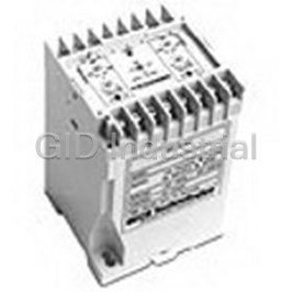
TE CONNECTIVITY 1618058-6
Description
Electromechanical Relay 100 to 200VDC 100 to 140VAC 5A DPDT(73x112)mm DIN Rail Paralleling Relay
1618058-6
Part Number
1618058-6
Price
Request Quote
Manufacturer
TE CONNECTIVITY
Lead Time
Request Quote
Category
Relays and I/O Modules » Relay Other
Specifications
Manufacturer
TE Connectivity
Manufacturers Part #
1618058-6
Industry Aliases
WD25-013
Sub-Category
Other Relays
Brand
Raychem Wire and Tubing
Factory Pack Quantity
1
Datasheet
DDEController?Action=srchrtrv&DocNm=5-1773450-5_Section11&DocType=CS&DocLang=English&s_cid=1046.pdf
6119 KiB

Extracted Text
Protective Relays Protective Relays Table of Contents KILOVAC WD Series, DIN Rail or Screw Mounted Protective Relays Introduction . . . . . . . . . . . . . . . . . . . . . . . . . . . . . . . . . . . . . . . . . . . . . . . . . . . . . . . . . .11-2 KILOVAC WD25 Paralleling Relays . . . . . . . . . . . . . . . . . . . . . . . . . . . . . . . . . . . . . . . .11-3 KILOVAC WD2759 Over/Undervoltage Relays . . . . . . . . . . . . . . . . . . . . . . . . . .11-4, 11-5 KILOVAC WD32 Reverse Power Relays . . . . . . . . . . . . . . . . . . . . . . . . . . . . . . .11-6, 11-7 KILOVAC WD47 Phase Sequence Relays . . . . . . . . . . . . . . . . . . . . . . . . . . . . . . . . . .11-8 KILOVAC WD5051 1Ø and 3Ø Overcurrent Relays . . . . . . . . . . . . . . . . . . . . . .11-9, 11-10 KILOVAC WD81OU Over/Underfrequency Relays . . . . . . . . . . . . . . . . . . . . . . . . . . .11-11 Voltage Sensitive Relays WUV/WOV DC Series . . . . . . . . . . . . . . . . . . . . . . . . . . . . . . . . . . . . . . . . . . . . . . . . .11-12 WUV/WOV Series . . . . . . . . . . . . . . . . . . . . . . . . . . . . . . . . . . . . . . . . . . . . . . . . . . . .11-13 WUVT/WOVT Series . . . . . . . . . . . . . . . . . . . . . . . . . . . . . . . . . . . . . . . . . . . . . . . . . .11-14 WOUV DC Series, Over/Undervoltage . . . . . . . . . . . . . . . . . . . . . . . . . . . . . . . . . . . .11-15 WOUVT Series, Over/Undervoltage . . . . . . . . . . . . . . . . . . . . . . . . . . . . . . . . . . . . . .11-16 250 Series, Over/Undervoltage . . . . . . . . . . . . . . . . . . . . . . . . . . . . . . . . . . . . . . . . . .11-17 D100X Series, Close Differential . . . . . . . . . . . . . . . . . . . . . . . . . . . . . . . . . . . . . . . . .11-18 D101X Series, 3 Phase Adjustable, Close Differential . . . . . . . . . . . . . . . . . . . . . . . .11-19 Reverse Power Relay 700 Series w/ Adjustable Time Delay . . . . . . . . . . . . . . . . . . . . . . . . . . . . . . . . . . . . .11-20 11 Phase Failure Relay 1000 Series . . . . . . . . . . . . . . . . . . . . . . . . . . . . . . . . . . . . . . . . . . . . . . . . . . . . . . . .11-21 Phase Sequence Relay 900 Series . . . . . . . . . . . . . . . . . . . . . . . . . . . . . . . . . . . . . . . . . . . . . . . . . . . . . . . . .11-22 Current Balance Relay WCB Series . . . . . . . . . . . . . . . . . . . . . . . . . . . . . . . . . . . . . . . . . . . . . . . . . . . . . . . .11-23 Current Sensitive Relays WC1 & WCT1 Series, Overcurrent . . . . . . . . . . . . . . . . . . . . . . . . . . . . . . . . . . . . . . .11-24 WC3 & WCT3 Series, Overcurrent . . . . . . . . . . . . . . . . . . . . . . . . . . . . . . . . . . . . . . .11-25 Current Differential Relay WCD Series . . . . . . . . . . . . . . . . . . . . . . . . . . . . . . . . . . . . . . . . . . . . . . . . . . . . . . . . .11-26 Paralleling Relays 1800 Series . . . . . . . . . . . . . . . . . . . . . . . . . . . . . . . . . . . . . . . . . . . . . . . . . . . . . . . . .11-27 Selection Guide . . . . . . . . . . . . . . . . . . . . . . . . . . . . . . . . . . . . . . . . . . . . . . . . . . . . . .11-27 Frequency Sensitive Relays WOF & WUF Series . . . . . . . . . . . . . . . . . . . . . . . . . . . . . . . . . . . . . . . . . . . . . . . . . .11-28 WOUF Series, Over/Underfrequency . . . . . . . . . . . . . . . . . . . . . . . . . . . . . . . . . . . . .11-29 20-000 Series . . . . . . . . . . . . . . . . . . . . . . . . . . . . . . . . . . . . . . . . . . . . . . . . . . . . . . .11-30 25-000 Series . . . . . . . . . . . . . . . . . . . . . . . . . . . . . . . . . . . . . . . . . . . . . . . . . . . . . . .11-31 20-050-19 Series (Voltage/Frequency) . . . . . . . . . . . . . . . . . . . . . . . . . . . . . . . . . . . .11-32 Ground Fault Relays WGD Series — Floating Ground . . . . . . . . . . . . . . . . . . . . . . . . . . . . . . . . . . . . . . . . .11-33 WC1G Series — Grounded . . . . . . . . . . . . . . . . . . . . . . . . . . . . . . . . . . . . . . . . . . . . .11-34 Additional Relays . . . . . . . . . . . . . . . . . . . . . . . . . . . . . . . . . . . . . . . . . . . . . . . .11-35 – 11-43 11–1 Catalog 5-1773450-5 Dimensions are shown for Dimensions are in millimeters USA: +1 800 522 6752 For additional support numbers Revised 3-13 reference purposes only. unless otherwise specified. Asia Pacific: +86 0 400 820 6015 please visit www.te.com Specifications subject UK: +44 800 267 666 www.te.com to change. Protective Relays KILOVAC WD Series, DIN Rail or Screw Mounted Protective Relays Product Facts n WD25 Paralleling (Synch Check) Relays n WD2759 Over/undervoltage Maintenance — WD series protective Installation and Maintenance Relays relays are solid state devices that require Information no maintenance. They are not designed n WD32 Reverse Power Installation — To mount the WD to be serviced by the user. Consult Relays series protective relay on a DIN rail, KILOVAC customer service at 805-220- hook the top edge of the cutout on the n WD47 Phase Sequence 2023 if repairs should be necessary. base of the case over one edge of the Relays DIN rail, then press the opposite side of n WD5051 Single- or Three- the cutout containing the release clip over the opposite side of the DIN rail. To Phase Overcurrent Relays remove or reposition the relay, lever the n WD81OU release clip and move the relay as Over/Underfrequency Relays required. WD series relays should be installed in a dry location where the n File E58048, The WD series offers ambient temperature will be within the DIN EN50022-35 R several different models operating temperature range. of protective relays in a common package that is suitable for either DIN rail or screw mounting. These flexible, multifunction Outline Dimensions devices offer user selectable Users should thoroughly review the voltages, sense currents technical data before selecting a product 16 X M3.5 and frequencies. Adjustable part number. It is recommended that user time delays are standard. also seek out the pertinent approvals files of the agencies/laboratories and This allows a single part review them to ensure the product meets number to be suitable for the requirements for a given application. multiple applications, 1.38 2.87 thereby reducing inventory (35.0) (73.0) costs. Specifications Common to All Models Power Consumption — 2.5VA, maximum. Contact Ratings — 5 amps, resistive, at 120VAC. 5 amps, resistive, at 30VDC. Isolation from Control to Sense Inputs — 2,500VAC. 4.41 Mechanical Life — (112.0) 10 million operations. Shock — 10g. Vibration — 0.062 (1.57) double amplitude at 10-55 Hz. 0.35 (9.0) Terminals — M3.5 screws. Maximum Wire Size — 2 x 24 AWG 2 (2.5mm ) solid to DIN 46288 or 2 x 16 2 AWG (1.5mm ) stranded w/end sleeves. 2.95 (75.0) Operating Temperature Range — -40°C to +60°C. Enclosure — Plastic case (not sealed). M5 2.36 M4 (60.0) Mounting Options — Snap mounts on standard DIN rail (DIN-EN 50022-35) or panel mounts with M4, M5, #8 or #10 screws. 2.36 (60.0) Weight — 14.4 oz. (400g) approxi- mately. 1.97 (50.0) 11–2 Catalog 5-1773450-5 Dimensions are shown for Dimensions are in millimeters USA: +1 800 522 6752 For additional support numbers Revised 3-13 reference purposes only. unless otherwise specified. Asia Pacific: +86 0 400 820 6015 please visit www.te.com Specifications subject UK: +44 800 267 666 www.te.com to change. Protective Relays Protective Relays KILOVAC WD25 Paralleling Relays Sense Voltage Product Facts Voltage (nominal) 120 208 277 480 n Function 25 Synch Voltage (% of nom.) 6 - 30% (≈ 4°- 20° electrical degree) n ANSI/IEEE C37.90-1978 Dead Bus Voltage (% of nom.) 10 - 70% (Dead Bus) Control Voltage Model WD25 -0X1 -0X2 -0X3 WD25 Operation WD25 Specifications Input Voltage (VDC) 18 to 54 13.5 to 32 100 to 200 Nominal Operating Range — WD25 paralleling relays Input Voltage (VAC) —— 100 to 140 120, 208, 277 or 480 VAC, selectable. are used to ensure that two Maximum Sensing Range — circuits are synchronized. 575VAC. When voltage, phase WD25 Controls Nominal Frequency Range — relationship and frequency 40-400 Hz. are within the selected Contact Form — 2 form C (DPDT). synchronizing limits, the output relay will energize. WD25 Calibration The WD25 paralleling relay The calibration marks on the faceplate allows for a generator to be are provided only as guides. Proper brought online without dam- calibration requires using an accurate voltmeter. Use the following procedure age or system disturbance. to calibrate the WD25: WD25 series with a "dead 1. Remove the cover. bus" feature will energize for a synchronized condition or 2. Adjust the SYNC VOLTAGE control fully counterclockwise (CCW). Apply an "on line" generator, "dead nominal voltage to the LINE B (bus) bus" condition. This "dead 11 sensing terminals. bus" feature allows the gen- WD25 Connections 3. Apply the maximum desired erator to energize a dead synchronization voltage to the LINE A bus. The "double dead bus" (generator) terminals. This voltage feature permits paralleling should be in phase with LINE B (bus) of two buses when: (a) both voltage and have the same frequency. the line voltages are equal 4. Slowly adjust the SYNC VOLTAGE and in phase, or (b) when control clockwise (CW) until the relay either bus is "hot" and the energizes. other bus is "dead." WD25 Typical Hookup Ordering Information Typical Part Number WD 25 -00 2 1. Basic Series: WD = DIN mount Protective Relay. 2. Type: 25 = Paralleling Relay. 3. Dead Bus: 00 = Double Dead Bus 01 = Single Dead Bus 02 = Generator to Generator 4. Control Voltage: 1 = 18 to 54VDC 2 = 13.5 to 32 VDC 3 = 100-200VDC or 100-140VAC. Our authorized distributors are more likely to stock these items. NOTE: For single dead bus option, WD25-001 connect the generator to 1 & 3 and WD25-013 the bus to 5 & 7. 11–3 Catalog 5-1773450-5 Dimensions are shown for Dimensions are in millimeters USA: +1 800 522 6752 For additional support numbers Revised 3-13 reference purposes only. unless otherwise specified. Asia Pacific: +86 0 400 820 6015 please visit www.te.com Specifications subject UK: +44 800 267 666 www.te.com to change. Protective Relays KILOVAC WD2759 Over/Undervoltage Relays WD2759 Operation Sense Voltage Product Facts Voltage (nominal) 120 208 277 480 WD2759 AC voltage sens- n Function 27/59 UV Adjustment Range 72-120 125-208 166-277 288-480 ing relays provide voltage n ANSI/IEEE C37.90-1978 OV Adjustment Range 120-168 208-291 277-388 480-672 monitoring and protection in AC systems from 50 to 400 Hz. Sensing voltages, Control Voltage number of phases, over and Model WD2759 -001 -002 -003 undervoltage setpoint, and Input Voltage (VDC) 18 to 54 13.5 to 32 100 to 200 time delays are user config- Input Voltage (VAC) —— 100 to 140 ured. WD2759 voltage relays operate when the 5. Remove the applied voltage (do not externally adjustable trip WD2759 Specifications change the voltage level) and set the point is reached. An exter- Nominal Operating Range — TIME DELAY control to the desired nal time delay control is 120, 208, 277 or 480 VAC, selectable. time delay. provided with an adjustment Maximum Sensing Range — 6. Apply the trip voltage to the relay and of .5 to 10 seconds. This 700VAC. measure the time to trip. time delay may be used to Nominal Frequency Range — 7. Adjust the TIME DELAY and repeat prevent false tripping when 50-400 Hz. steps 4 and 5 until you have the there are slight variations Contact Form — 1 form C (SPDT) for desired time delay. in the voltage supply. On undervoltage and 1 form C (SPDT) for UNDER VOLTAGE overvoltage. overvoltage (OV) the output 1. Remove cover. relay energizes when the Time Delay Adjustment — 2. Adjust the TRIP SET control fully 0.5 to 10 sec. CCW and the TIME DELAY control input signal exceeds the trip fully CCW. point. On undervoltage WD2759 Calibration 3. Decrease the applied sensing voltage (UV) the output relay ener- The calibration marks on the faceplate from the nominal value until the gizes when the input signal have a maximum error of 10% and are desired tripping voltage is reached. goes below the trip point. provided only as guides. Proper 4. Slowly adjust the TRIP SET control A green LED indicates calibration requires using an accurate CW until the relay trips. power to the relay. Red voltmeter in parallel with the input 5. Set the TIME DELAY control to the signal. Use the following procedure to LED lights indicate the state desired time delay and apply nominal calibrate your relay. of the undervoltage and voltage to the relay. OVER VOLTAGE 6. Step down the applied voltage from overvoltage trips. 1. Remove cover. nominal to a level jest below the trip 2. Adjust the TRIP SET control fully level set in Step 3 and measure the clockwise (CW) and the TIME DELAY time delay. control fully counterclockwise (CCW). 7. Adjust the TIME DELAY and repeat 3. Apply the desired trip voltage to the steps 4 and 5 until the desired time relay. delay is achieved. 4. Slowly adjust the TRIP SET control CCW until the relay trips. Ordering Information Typical Part Number WD 2759 -002 1. Basic Series: WD = DIN mount Protective Relay. 2. Type: 2759 = Over/Undervoltage Relay. 3. Control Voltage: 001 = 18 to 54VDC 002 = 13.5 to 32 VDC 003 = 100-200VDC or 100-140VAC. Our authorized distributors are more likely to stock these items. WD2759-003 11–4 Catalog 5-1773450-5 Dimensions are shown for Dimensions are in millimeters USA: +1 800 522 6752 For additional support numbers Revised 3-13 reference purposes only. unless otherwise specified. Asia Pacific: +86 0 400 820 6015 please visit www.te.com Specifications subject UK: +44 800 267 666 www.te.com to change. Protective Relays Protective Relays KILOVAC WD2759 Over/Undervoltage Relays (Continued) WD2759 Controls WD2759 Connections 11 WD2759 Typical Hookup 11–5 Catalog 5-1773450-5 Dimensions are shown for Dimensions are in millimeters USA: +1 800 522 6752 For additional support numbers Revised 3-13 reference purposes only. unless otherwise specified. Asia Pacific: +86 0 400 820 6015 please visit www.te.com Specifications subject UK: +44 800 267 666 www.te.com to change. Protective Relays KILOVAC WD32 Reverse Power Relays WD32 Operation Control Voltage Product Facts Model WD32 -001 -002 -003 WD32 reverse power relays n Function 32 Input Voltage (VDC) 18 to 54 13.5 to 32 100 to 200 are used to monitor the Input Voltage (VAC) —˜ 100 to 140 direction of power from AC generators. This is accom- plished by measuring I cos WD32 Calibration q. If current from the gener- The calibration marks on the faceplate ator is reversed and have a maximum error of 10% and exceeds the adjustable set- are provided only as guides. Proper ting, the relay will trip. A 0.5 calibration requires using an accurate to 20 second time delay is Current Meter in series with the input provided. A correct setting current. Use the following procedure to of the trip point and time calibrate your relay. delay will prevent motoriz- REVERSE POWER ing the generator and pre- 1. Remove cover. vent tripping during 2. Adjust the TRIP SET control fully transients that occur while clockwise (CW) and the TIME DELAY synchronizing. A POWER control fully counterclockwise (CCW). LED indicates the condition 3. Apply the desired trip current to the of the power supply and a relay. NOTE: for the Reverse Power REVERSE POWER TRIP (WD32-00X) a resistive load must LED indicates the output be used and for the Reverse kVAR (WD32-01X) an inductive load must status of the relay. be used. WD32 Specifications 4. Slowly adjust the TRIP SET control Nominal Operating Range — CCW until the relay trips. 120 to 480 VAC, 1 or 3 phase. 5. Remove the applied Current and set Maximum Sensing Range — the TIME DELAY control to the 575VAC. desired time delay. Nominal Sensing Current — 5A. 6. Re-apply the Current (10% more than Nominal Frequency Range — the trip current) to the relay and WD32-00X — 40-400 Hz.; measure the time to trip. WD32-01X — 60 Hz. 7. Adjust the TIME DELAY and repeat Contact Form — 2 form C (DPDT). steps 4 and 5 until you have the desired time delay. Time Delay Adjustment — 0.5 to 20 sec. Sense Current — Reverse Power Trip: 0.2 to 1.0A (4-20% of nominal sense current). Ordering Information Typical Part Number WD 32 -00 2 1. Basic Series: WD = DIN mount Protective Relay. 2. Type: 32 = Reverse Power Relay. 3. Load: 00 = Resistive (power) 01 = Inductive (kVAR, 60 Hz.) 4. Control Voltage: 1 = 18 to 54VDC 2 = 13.5 to 32 VDC 3 = 100-200VDC or 100-140VAC. Our authorized distributors are more likely to stock these items. WD32-003 WD32-011 11–6 Catalog 5-1773450-5 Dimensions are shown for Dimensions are in millimeters USA: +1 800 522 6752 For additional support numbers Revised 3-13 reference purposes only. unless otherwise specified. Asia Pacific: +86 0 400 820 6015 please visit www.te.com Specifications subject UK: +44 800 267 666 www.te.com to change. Protective Relays Protective Relays KILOVAC WD32 Reverse Power Relays (Continued) WD32 Controls WD32 Connections 11 WD32 Typical Hookup 11–7 Catalog 5-1773450-5 Dimensions are shown for Dimensions are in millimeters USA: +1 800 522 6752 For additional support numbers Revised 3-13 reference purposes only. unless otherwise specified. Asia Pacific: +86 0 400 820 6015 please visit www.te.com Specifications subject UK: +44 800 267 666 www.te.com to change. Protective Relays KILOVAC WD47 Phase Sequence Relays Control Voltage Product Facts Model WD47 -001 -002 -003 n Function 47 Input Voltage (VDC) 18 to 54 13.5 to 32 100 to 200 n ANSI/IEEE C37.90-1978 Input Voltage (VAC) —— 100 to 140 WD47 Controls WD47 Operation WD47 Specifications Nominal Operating Range — WD47 phase sequence 120 to 480 VAC. relays are designed to Maximum Sensing Range — monitor the correct phase 575VAC. rotation and loss of phase Nominal Frequency Range — of three phase ac systems 40-400 Hz. from 50 to 400 Hz. An Contact Form — 2 form C (DPDT). incorrect phase sequence or loss of any phase will WD47 Calibration cause the WD47 to pickup. The WD47 has no adjustments and When the phase sequence no calibration is necessary. Proper is corrected or the lost operation may be verified as follows: phase is restored the 1. Apply a nominal, three-phase input contacts dropout. Red with the correct phase sequence. The output relay should dropout and LED's light to indicate a the green LED should light. WD47 Connections fault condition. A green 2. Apply a nominal, three-phase input LED indicates power to the with an incorrect phase sequence. relay. The WD47 is often The output relay should pickup and used to detect reverse the red LED should light. phase rotation or loss of 3. Apply only one or two phases with phase to generators, busses, the correct phase sequence. The motors, and transformers. output relay should pickup and the red LED should light. WD47 Typical Hookup Ordering Information Typical Part Number WD 47 -002 1. Basic Series: WD = DIN mount Protective Relay. 2. Type: 47= Phase Sequence Relay. 3. Control Voltage: 001 = 18 to 54VDC 002 = 13.5 to 32 VDC 003 = 100-200VDC or 100-140VAC. Our authorized distributors are more likely to stock these items. WD47-001 11–8 Catalog 5-1773450-5 Dimensions are shown for Dimensions are in millimeters USA: +1 800 522 6752 For additional support numbers Revised 3-13 reference purposes only. unless otherwise specified. Asia Pacific: +86 0 400 820 6015 please visit www.te.com Specifications subject UK: +44 800 267 666 www.te.com to change. Protective Relays Protective Relays KILOVAC WD5051 1Ø and 3Ø Overcurrent Relays WD5051 Operation Sense Current Product Facts Current (nominal) 13 68 WD5051 AC current sens- n Function 5051 IOC 0.2 to 1.2 0.6 to 3.6 1.2 to 7.2 1.6 to 9.6 ing relays provide current TOC 0.2 to 1.2 0.6 to 3.6 1.2 to 7.2 1.6 to 9.6 monitoring and protection in AC systems from 50 to 400 Hz. Nominal Sensing Control Voltage Current, Instantaneous Over Model WD5051 -001 -002 -003 Current setpoint, Time Over Input Voltage (VDC) 18 to 54 13.5 to 32 100 to 200 Current setpoint, and Time Input Voltage (VAC) —— 100 to 140 Over Current time delay are user configured. WD5051 WD5051 Specifications WD5051 Calibration current relays operate when Sense Current Full Scale — 1, 3, 6 The calibration marks on the faceplate the externally adjustable trip or 8A, selectable. are provided only as guides. Proper cal- point is reached. An exter- ibration requires using an accurate Maximum Sensing Current — nal time over current time ammeter in series with the current 10A continuous; 30A for 10 sec.; delay control is provided source. Use the following procedure to 60A for 2.5 sec.; 100A for 0.9 sec.. with an adjustment of .5 to calibrate your relay: Nominal Frequency Range — 20 seconds. This time delay OVERCURRENT 50-400 Hz. may be used to prevent 1. Remover the cover. Contact Form — 1 form C (SPDT) for false tripping when there IOC and 1 form C (SPDT) for TOC. 2. Adjust the TRIP SET control fully are slight variations in the clockwise (CW) and the TIME DELAY TOC Time Delay Adjustment — sensed current. With control control (TOC only) fully counter- 0.5 to 20 sec. power applied, the clockwise (CCW). IOC Operate Time (max.) — Instantaneous Over Current 3. Apply the desired trip current to the 0.2 sec. (IOC) contacts pick-up relay. 11 when the input signal 4. Slowly adjust the TRIP SET control exceeds the IOC trip set- CCW until the relay trips. point. Similarly, with control 5. Remove the applied current (do not power applied, the Time change the current level). Set the TIME DELAY (TOC only) control to Over Current (TOC) con- the desired time delay. tacts pick-up after the pre- set time delay when the Sense Current rises above the TOC trip setpoint. The IOC contacts may also be configured to function as an under current relay. A green LED indicates power to the relay. Red LED lights indicate the state of the IOC and TOC trips. Ordering Information Typical Part Number WD 5051 -002 1. Basic Series: WD = DIN mount Protective Relay. 2. Type: 5051 = Single Phase Overcurrent Relay. 5051-3 = Three Phase Overcurrent Relay. 3. Control Voltage: 001 = 18 to 54VDC 002 = 13.5 to 32 VDC 003 = 100-200VDC 0r 100-140VAC. Our authorized distributors are more likely to stock these items. WD5051-001 WD5051-003 WD5051-3-001 11–9 Catalog 5-1773450-5 Dimensions are shown for Dimensions are in millimeters USA: +1 800 522 6752 For additional support numbers Revised 3-13 reference purposes only. unless otherwise specified. Asia Pacific: +86 0 400 820 6015 please visit www.te.com Specifications subject UK: +44 800 267 666 www.te.com to change. Protective Relays KILOVAC WD5051 1Ø and 3Ø Overcurrent Relays (Continued) WD5051 Controls WD5051 Connections WD5051 Single Phase Model WD5051-3 Three Phase Model WD5051 Typical Hookup WD5051 WD5051-3 Single Phase Model Three Phase Model 11–10 Catalog 5-1773450-5 Dimensions are shown for Dimensions are in millimeters USA: +1 800 522 6752 For additional support numbers Revised 3-13 reference purposes only. unless otherwise specified. Asia Pacific: +86 0 400 820 6015 please visit www.te.com Specifications subject UK: +44 800 267 666 www.te.com to change. Protective Relays Protective Relays KILOVAC WD81OU Over/Underfrequency Relays Sense Frequency Product Facts Frequency (nominal) 50 60 400 n Function 81 OU UF Adjustment Range 40-50 48-60 360-400 n ANSI/IEEE C37.90-1978 OF Adjustment Range 50-60 60-72 400-480 Control Voltage WD81OU Operation WD81OU Calibration Model WD81OU -001 -002 -003 The calibration marks on the faceplate WD81OU frequency Input Voltage (VDC) 18 to 54 13.5 to 32 100 to 200 are provided only as guides. Proper relays are used to provide Input Voltage (VAC) —— 100 to 140 calibration requires using an accurate frequency monitoring and frequency meter in parallel with the input protection to generators, signal. WD81OU Controls buses, power supplies, and UNDER FREQUENCY other equipment. The relay 1. Remove the cover. operates at voltages from 2. Set the SENSE FREQUENCY to the nominal system frequency. Adjust the 120 to 480 Vac and at Under Frequency TRIP SET fully nominal frequencies of 50, clockwise (CW) and the TIME DELAY 60, and 400 Hz. External control fully counterclockwise (CCW). controls include nominal 3. Apply the desired trip frequency to frequency selection, under the relay. frequency (UF) trip set, 4. Slowly adjust the TRIP SET control over frequency (OF) trip CCW until the relay trips. set, UF time delay, and OF 5. Set the TIME DELAY control to the time delay. A green LED desired time delay and apply nominal frequency to the relay. indicates power to the 6. Step down the applied frequency relay. Red LED’s indicate 11 from nominal to just below the trip the status of the UF and level set in Step 4 and measure the WD81OU Connections OF trips. time delay. WD81OU Specifications 7. Adjust the TIME DELAY and repeat steps 5 and 6 until the desired time Nominal Operating Frequency — delay is set. 50, 60 or 400 Hz., selectable. OVER FREQUENCY Maximum Frequency @ 400 Hz. 1. Remove the cover. Nominal — 1000 Hz. 2. Set the SENSE FREQUENCY to the Nominal Sensing Voltage — nominal system frequency. Adjust 20-480VAC. the OF TRIP SET and TIME DELAY Maximum Sensing Voltage — controls fully counterclockwise (CCW). 575VAC. 3. Apply the desired trip frequency to the relay. Contact Form — 1 form C (SPDT) for 4. Slowly adjust the TRIP SET control underfrequency and 1 form C (SPDT) for clockwise (CW) until the relay trips. overfrequency. WD81OU Typical Hookup 5. Set the TIME DELAY control to the Time Delay Adjustment — 0.5 to 10 desired time delay and apply nominal sec. frequency to the relay. 6. Step down the applied frequency from nominal to just below the trip level set in Step 4 and measure the time delay. 7. Adjust the TIME DELAY and repeat steps 5 and 6 until the desired time delay is set. Ordering Information Typical Part Number WD 81OU-002 1. Basic Series: WD = DIN mount Protective Relay. 2. Type: 81OU = Over/Underfrequency Relay. 3. Control Voltage: 001 = 18 to 54VDC 002 = 13.5 to 32 VDC 003 = 100-200VDC or 100-140VAC. Our authorized distributors are more likely to stock these items. None at present. 11–11 Catalog 5-1773450-5 Dimensions are shown for Dimensions are in millimeters USA: +1 800 522 6752 For additional support numbers Revised 3-13 reference purposes only. unless otherwise specified. Asia Pacific: +86 0 400 820 6015 please visit www.te.com Specifications subject UK: +44 800 267 666 www.te.com to change. Protective Relays WUV/WOV DC Series Product Specifications Product Facts Nominal Voltage — 12 VDC to 560 n ANSI/IEEE C37.90-1978 VDC Drop-out Point (u/v models) — 70-100% of nominal voltage, screwdriver adjustable Undervoltage Models Pick-Up Point (o/v models) — The relay is energized at 100-125% of nominal voltage, screwdriver adjustable normal voltage, N.C. con- tacts will open and N.O. Output Contacts — One set N.O., One set N.C. contacts will close. The relay will de-energize when Contact Ratings — 5 amp resistive at 120 VAC or 28 VDC the voltage drops below the U/V set point. Operating Temperature Range — -40˚C to +75˚C Overvoltage Models Temperature Effects — Less than The relay is de-energized at 1% voltage drift over the temperature normal voltage, N.C. con- range tacts are closed and N.O. Power Consumption — contacts are open. The 12 to 60 VDC models — 1 W max. relay will energize, when the 120 to 305 VDC models — 2 W max. voltage rises above the O/V 405 to 470 VDC models — 3 W max. set point. 560 VDC model — 4 W max. Note: Dimensions in inches. Multiply values by 25.4 for dimensions in mm. Time Delay — A short duration delay is provided to prevent nuisance tripping due to momentary dips or surges in volt- age. The drop-out delay, following a voltage fault is 75 to 100 milliseconds. (+) (–) Notes: 1. Remove black screws for access to the O/V and U/V trip adjustment. 2. Clockwise rotation of the adjust- ment potentiometer will raise the voltage trip point. 3. The adjustments are by means of a single turn potentiometer. Use a small screwdriver and do not force beyond the limit stops. Ordering Information Sample Part Number WOV-12DC -A Type: WOV - Overvoltage WUV - Undervoltage Line Voltage VDC 12DC 125DC 18DC 240DC 24DC 250DC 28DC 305DC 32DC 405DC 48DC 430DC 60DC 470DC 120DC 560DC Transient Protection — All voltage relays will withstand momentary voltage Options: surges of twice the nominal rated input Blank - Standard voltage (standard). A = 2 Form A Contacts Option “P” provides additional tran- B = 2 Form B Contacts sient protection which complies with the H = 125 VDC Contacts requirements of ANSI/IEEE C37.90-1978 P = Transient Protection Consult factory for additional models. 11–12 Catalog 5-1773450-5 Dimensions are shown for Dimensions are in millimeters USA: +1 800 522 6752 For additional support numbers Revised 3-13 reference purposes only. unless otherwise specified. Asia Pacific: +86 0 400 820 6015 please visit www.te.com Specifications subject UK: +44 800 267 666 www.te.com to change. Protective Relays 1 3 /2 3.0 7 3 /8 Protective Relays WUV/WOV Series TERMINAL STRIPS Product Specifications Product Facts #6 - 32 SCREWS Nominal Voltage — 120 VAC to 575 n Function 27/59 VAC n ANSI/IEEE C37.90-1978 Phase — Single or Three Line Frequency — 50-400 Hz n UL File No. E58048 R Pick-up to Drop-out Differential — n CSA File No. LR61158 2.5% maximum R Drop-out Point (u/v models) — 70-100% of nominal voltage, screwdriver adjustable Pick-Up Point (o/v models) — 100-125% of nominal voltage, Voltage sensitive relays are screwdriver adjustable available for both AC and Output Contacts — One set N.O., DC applications for One set N.C. over/undervoltage protec- Contact Ratings — tion. Combination 5 amp resistive at 120 VAC or 28 VDC over/undervoltage relays Operating Temperature Range — provide bandpass capabili- -20˚C to +65˚C ties. AC relays are either Power Consumption — single or three-phase type. 2 VA maximum Three phase models are Time Delay — 150-300 ms (UV Model) designed to sense the aver- Note: Dimensions in inches. Multiply values by 25.4 for dimensions in mm. Minimum Life — 500,000 operations age of the three phases or the highest single phase. Voltage trip points are 11 Notes: screwdriver adjustable, and 1. Remove black screw for access to the voltage trip adjustment. operation is time-delayed so 2. C lockwise rotation of the adjust- that momentary voltage ment potentiometer will raise the transients will not cause nui- voltage trip point. sance tripping. Single Phase Three Phase Typical Time Curve Ordering Information 40.0 Sample Part Number WUV -1 -120 30.0 Overvoltage Relays Type: WOV Series WUV - Undervoltage 20.0 WOV - Overvoltage No. Phases 10.0 1 = Single 3 = Three 0.0 Line Voltage VAC 120 416 -10.0 208 440 00.05 0.1 0.15 0.2 0.25 0.3 220 460 Pick-Up Time Delay 230 480 240 525 Transient Protection — All voltage 380 575 relays will withstand momentary voltage Options surges of twice the nominal rated input P - Transient Protection voltage (standard). A - Two Normally Open Contacts Option “P” provides additional tran- B - Two Normally Closed Contacts sient protection which complies with the H - 125VDC, 3A Contacts requirements of ANSI/IEEE C37.90-1978 Consult factory for additional models. 11–13 Catalog 5-1773450-5 Dimensions are shown for Dimensions are in millimeters USA: +1 800 522 6752 For additional support numbers Revised 3-13 reference purposes only. unless otherwise specified. Asia Pacific: +86 0 400 820 6015 please visit www.te.com Specifications subject UK: +44 800 267 666 www.te.com to change. 11 /64" DIA. 4 MTG. HOLES 3.0 3 2 /4 1 3 /2 Voltage Above Set Point 1 4 /2 5 3 /8 1 4 /8 Protective Relays WUVT/WOVT Series Product Specifications Product Facts Nominal Voltage — 100 VAC to 575 n Function 27/59 TERMINAL STRIPS VAC #6 - 32 SCREWS n ANSI/IEEE C37.90-1978 Phase — Single or Three Line Frequency — 50-400 Hz n UL File No. E58048 R Pick-up to Drop-out Differential — n CSA File No. LR61158 1% typical R 3.0 Drop-out Point (u/v models) — 70-100% of nominal voltage, screwdriver adjustable Pick-Up Point (o/v models) — 100-125% of nominal voltage, Undervoltage Models screwdriver adjustable The relay is energized at Output Contacts — One set N.O., normal voltage, N.C. con- One set N.C. tacts will open and N.O. Contact Ratings — contacts will close. The 5 amp resistive at 120 VAC or 28 VDC relay will de-energize when Operating Temperature Range — the voltage drops and -40˚C to +70˚C remains below the U/V set Power Consumption — point for the duration of the 11 /64" DIA. 3 VA maximum set time delay. 4 MTG. HOLES Time Delay — 0.5 to 20 seconds, Overvoltage Models screwdriver adjustable Note: Dimensions in inches. Multiply values by 25.4 for dimensions in mm. The relay is de-energized at Voltage Reset — The reset is auto- normal voltages, N.C. con- matic when voltage returns to normal. tacts are closed and N.O. contacts are open. The Notes: relay will energize, when the 1. Remove black screws for access voltage rises and remains to the voltage and time delay adjustment potentiometer. above the O/V set point for 2. Clockwise rotation of the voltage the duration of the set time adjust potentiometer will raise the delay. voltage trip point. 3. Clockwise rotation of the time adjust potentiometer will increase the time delay (Pick-up time for O/V models, drop-out time for U/V Single Phase Three Phase models). 4. The adjustments are single turn potentiometers, use a small Ordering Information screwdriver and do not force beyond the limit stops. 5. On U/V models, when the voltage Sample Part Number WUVT -1 -120 falls to approximately 33% of nominal or below, the relay will Type: drop out in 0.150 to 0 .300 sec- WUVT - Undervoltage onds, regardless of the time delay WOVT - Overvoltage setting. No. Phases 1 = Single 3 = Three (line to line) Line Voltage VAC 100 240 115 380 120 416 150 440 200 460 208 480 Transient Protection — All voltage 220 525 relays will withstand momentary voltage 230 575 surges of twice the nominal rated input voltage (standard). Options: Option “P” provides additional tran- Blank - Standard sient protection which complies with the A = 2 Form A Contacts requirements of ANSI/IEEE C37.90-1978 B = 2 Form B Contacts Consult factory for additional H = 125VDC 3A Contacts models. P = Transient Protection 11–14 Catalog 5-1773450-5 Dimensions are shown for Dimensions are in millimeters USA: +1 800 522 6752 For additional support numbers Revised 3-13 reference purposes only. unless otherwise specified. Asia Pacific: +86 0 400 820 6015 please visit www.te.com Specifications subject UK: +44 800 267 666 www.te.com to change. 1 4 /4 1 3 /2 Protective Relays 3 3 7/8 3 1/2 11/64" DIA. 4 MTG. HOLES Protective Relays WOUV DC Series, Over/Undervoltage Product Specifications Product Facts Nominal Voltage (±10%) — n ANSI/IEEE C37.90-1978 12 VDC to 560 VDC Drop-out Point (u/v models) — 70-100% of nominal voltage, screwdriver adjustable Pick-Up Point (o/v models) — The relay will energize at 13 100-125% of nominal voltage, 2 /16 normal voltage conditions. screwdriver adjustable The normally open contacts Output Contacts — One set N.O., will close, and the normally One set N.C. closed contacts will open. Contact Ratings — The relay will de-energize 5 amp resistive at 120 VAC or 28 VDC during over or undervoltage Operating Temperature Range — conditions. Reset is auto- -40˚C to +75˚C matic when the voltage Temperature Effects — returns to normal. Less than 1% voltage drift over the tem- perature range. Power Consumption — 12 to 60 VDC models — 1 W max. 120 to 305 VDC models — 2 W max. 405 to 470 VDC models — 3 W max. 560 VDC Model — 4 W max. Note: Dimensions in inches. Multiply values by 25.4 for dimensions in mm. Time Delay — A short duration delay is provided to prevent nuisance tripping due to momentary dips or surges in volt- 11 age. The drop-out delay, following a voltage fault is 75 to 100 milliseconds Notes: 1. Remove black screws for access to the O/V and U/V trip adjust- ment. 2. C lockwise rotation of the adjust- ment potentiometer will raise the Single Phase voltage trip point. 3. The adjustments are by means of a single turn potentiometer. Use a small screwdriver and do not force beyond the limit stops. Drop-Out Time Delay WOUV...DC Series Ordering Information 180 Sample Part Number WOUV -12DC -A 160 140 Type: 120 WOUV - Over/Undervoltage 100 Line Voltage VDC 80 12DC 125DC 60 18DC 240DC 24DC 250DC 40 28DC 305DC 20 32DC 405DC 0 48DC 430DC 020 40 60 80 100 120 140 60DC 470DC Time Delay (msec) 120DC 560DC Transient Protection — All voltage Options: relays will withstand momentary voltage Blank - Standard surges of twice the nominal rated input A = 2 Form A Contacts voltage (standard). B = 2 Form B Contacts Option “P” provides additional tran- H = 125 VDC Contacts sient protection which complies with the P = Transient Protection requirements of ANSI/IEEE C37.90-1978 Consult factory for additional models. 11–15 Catalog 5-1773450-5 Dimensions are shown for Dimensions are in millimeters USA: +1 800 522 6752 For additional support numbers Revised 3-13 reference purposes only. unless otherwise specified. Asia Pacific: +86 0 400 820 6015 please visit www.te.com Specifications subject UK: +44 800 267 666 www.te.com to change. 2.0 TERMINAL STRIPS #6 - 32 SCREWS 2 3/4 3 1/2 Percent of Nominal Voltage Protective Relays WOUVT Series, Over/Undervoltage Product Specifications Product Facts Nominal Voltage — 120 VAC to 575 n Function 27/59 VAC n ANSI/IEEE C37.90-1978 Phase — Single or Three Line Frequency — 50-400 Hz Type of Sensing — Average of all three phases Undervoltage Trip — 70-100% of Voltage sensitive relays are nominal voltage, screwdriver adjustable available for both AC and Overvoltage Trip — 100-125% of DC applications for overvolt- nominal voltage, screwdriver adjustable age and undervoltage Drop-out Time Delay — 0.5 to 20 protection. Combination seconds, screwdriver adjustable over/undervoltage relays Pick-up to Drop-out Differential — provide band-pass capabili- 2% maximum ties. AC relays are either Output Contacts — One set N.O., single or three-phase type. One set N.C. Three phase relays are Contact Ratings — 5 amp resistive at designed to sense the aver- 120 VAC or 28 VDC age of the three phases. Operating Temperature Range — Voltage trip points are -40˚C to +70˚C screwdriver adjustable, and Power Consumption — operation is time-delayed 4 VA maximum so that momentary voltage Note: Dimensions in inches. Multiply values by 25.4 for dimensions in mm. transients will not cause Notes: nuisance tripping. 1. Remove black screw for access to the voltage trip and time delay Operation adjustment potentiometer. The relay will energize at 2. Clockwise rotation of the voltage normal voltage condition. adjustment potentiometer will The normally closed contact raise the voltage trip point. 3. Clockwise rotation of the time (Form B) will open and the adjustment potentiometer will normally open (Form A) will increase the drop-out time delay. Single Phase Models Three Phase Models close. The relay will de- energize after time delay when over or undervoltage condition is reached. Ordering Information Sample Part Number WOUVT -1 -120AC Type: WOUVT - Over/Undervoltage No. Phases 1 = Single 3 = Three (line to line) Line Voltage VAC 115 120 200 208 220 230 240 380 Option “H” provides for contacts rating Options: of 3 amps @ 125VDC. Blank - Standard Option “P” provides additional tran- A = 2 Form A Contacts sient protection which complies with the B = 2 Form B Contacts requirements of ANSI/IEEE C37.90-1978 H = 125 VDC Contacts Consult factory for additional P = Transient Protection models. 11–16 Catalog 5-1773450-5 Dimensions are shown for Dimensions are in millimeters USA: +1 800 522 6752 For additional support numbers Revised 3-13 reference purposes only. unless otherwise specified. Asia Pacific: +86 0 400 820 6015 please visit www.te.com Specifications subject UK: +44 800 267 666 www.te.com to change. Protective Relays 3.500 B.C. 7 3 /8 3 Protective Relays 250 Series, Over/Undervoltage Product Specifications Product Facts Nominal Voltage — See Ordering n Function 27/59 Information 6 -32 STUDS (6) n ANSI/IEEE C37.90-1978 Undervoltage Trip — 70-100% of nominal voltage, screwdriver adjustable Overvoltage Trip — 100-125% of nominal voltage, screwdriver adjustable Pick-up to Drop-out Differential — The 250 series relays 3% maximum provide combined Contact Ratings — 5 amp resistive at Overvoltage and 120 VAC or 28 VDC Undervoltage protection in Contact Form — One set N.O., a single compact unit. one set N.C. Operating Temperature Range — Models are available for -20˚C to +85˚C single phase or three phase applications, and are suitable for either 50 Hz, Notes: 1. Remove screws for access the 60 Hz, or 400 Hz operation. overvoltage or undervoltage trip The trip point is adjustable. adjustments. Clockwise rotation of the adjustment potentiometer A transistorized circuit will raise the trip point. provides a sharp and accurate response at the Contact Arrangements preset tripping voltage; Note: Dimensions in inches. Multiply values by 25.4 for dimensions in mm. unaffected by temperature NC — Open at nominal voltage. Closed 11 at Overvoltage and Undervoltage or frequency variations. NO — Closed at nominal voltage. Open at Overvoltage and Undervoltage Single Phase Three Phase Ordering Information Sample Part Number 250X Model: L-L Volts 250X = 120 VAC, 1 Phase, 50-400 Hz 251X = 120/208 VAC, 3 Phase, 4 Wire, 50-400 Hz 252X = 115 VAC, 3 Phase, 3 Wire, 50-400 Hz 253X* = 230 VAC, 3 Phase, 3 Wire, 50-400 Hz 254X* = 380 VAC, 3 Phase, 3 Wire, 50-400 Hz 255X*= 460 VAC, 3 Phase, 3 Wire, 50-400 Hz 256X* = 575 VAC, 3 Phase, 3 Wire, 50-400 Hz Mounting Blank = Stud X = Flange * Enclosure height is 3.835" Consult factory for additional models. 11–17 Catalog 5-1773450-5 Dimensions are shown for Dimensions are in millimeters USA: +1 800 522 6752 For additional support numbers Revised 3-13 reference purposes only. unless otherwise specified. Asia Pacific: +86 0 400 820 6015 please visit www.te.com Specifications subject UK: +44 800 267 666 www.te.com to change. 2 13 /64" DIA. 4 MTG. HOLES 2.750 B.C. 3.500 Protective Relays D100X Series, Close Differential Product Specifications Product Facts Nominal Voltage — AC, Single n ANSI/IEEE C37.90-1978 Phase, see Ordering Information n UL File No. E58048 Nominal Frequency — 50 to 400 Hz. R Pick-Up Adjustment Range — n CSA File No. LR61158 R 67-100% of nominal voltage Drop-Out Adjustment Range — 67-100% of nominal voltage Maximum Differential Setting — 33% of nominal voltage Minimum Differential Setting — 2% of nominal voltage Close Differential Relays are Output Contacts — Form C (SPDT) voltage sensitive. The pick- Contact Ratings — 5 Amp resistive at up and drop-out voltage 120 VAC or 28 VDC settings are independently Operating Temperature Range — adjustable, which allows -20˚C to +85˚C precise setting of the differ- Expected Life — 10 million opera- ential voltage. This relay is tions available in a wide range of Inverse Time Drop-Out — AC and DC voltages. Their The differential relay contains a time primary application is the delay before operation so that momen- sensing and control of tary voltage transients do not affect the transfer switches. operation of the relay. The time delay Operation has an inverse time characteristic so that excessive voltage conditions will cause a Monitors a single phase more rapid drop-out. This time delay is AC signal, and is used for Note: Dimensions in inches. Multiply values by 25.4 for dimensions in mm. approximately 200mSec. (12 cycles) at undervoltage detection. the trip settings and decreases to 30 Has separate pick-up and mSec. at approximately 15% beyond the drop-out voltage settings, trip settings. providing an adjustable hysteresis. Notes: 1. Remove black nylon protective screws to gain access to the two internal adjustment potentiome- ters. 2. Clockwise rotation of the pick-up and drop-out adjustment will raise the voltage trip point. 3. The relay contacts are shown in the de-energized state. Ordering Information Sample Part Number D100X Model: L-L Volts Height D100X = 120 VAC 2" D100-6X = 120 VAC, Spike Suppression 2" D100-3X = 208 VAC 3.125" D100-4X = 240 VAC 3.125" D100-8X = 277 VAC 3.125" D100-5X = 480 VAC 3.125" D100-7X = 510 VAC 3.125" Surge Withstand Capability is in compliance with the requirements of ANSI/IEEE C37.90B Consult factory for additional models. 11–18 Catalog 5-1773450-5 Dimensions are shown for Dimensions are in millimeters USA: +1 800 522 6752 For additional support numbers Revised 3-13 reference purposes only. unless otherwise specified. Asia Pacific: +86 0 400 820 6015 please visit www.te.com Specifications subject UK: +44 800 267 666 www.te.com to change. Protective Relays 1 4 /4 1 5 /2 5.0 Protective Relays D101X Series, 3 Phase Adjustable, Close Differential Product Specifications Product Facts #6 - 32 STUDS Nominal Voltage — AC, Three Phase, n ANSI/IEEE C37.90-1978 10 PLACES see Ordering Information n UL File No. E58048 Nominal Frequency — 50 to 500 Hz. Pick-Up Adjustment Range — n CSA File No. LR61158 R 66-100% of nominal voltage, screw- driver adjustable R Drop-Out Adjustment Range — H2 66-100% of nominal voltage, screw- driver adjustable H1 Output Contacts — SPNO Close Differential Relays are Contact Ratings — 5 amp resistive at voltage sensitive. The pick- 120 VAC or 28 VDC up and drop-out voltage Operating Temperature Range — settings are independently -20˚C to +85˚C adjustable, which allows precise setting of the differ- ential voltage. This relay is Notes: 1. Remove screws for access to available in a wide range of pick-up and drop-out trip adjust- AC voltages. Their primary ments. application is the sensing 2. Clockwise rotation of the pick-up and control of transfer and drop-out adjustment will raise the voltage trip point. switches. Operation The output contacts will 13 /64" DIA. 11 close when the voltage of 4 MTG. HOLES all three phases is above the pre-set pick-up point, and will open when any Note: Dimensions in inches. Multiply values by 25.4 for dimensions in mm. one phase drops below its drop-out setting. Ordering Information Sample Part Number D101X Model: L-L Volts D101X = 120 VAC D101-6X = 208 VAC D101-4X = 240 VAC D101-10X = 380 VAC D101-7X = 480 VAC Power Consumption H1 H2 Model Each Phase (inches) (inches) D101X 2 VA max. 2 2 11/16 D101-4X 3 VA max. 3 1/2 4 3/16 D101-6X 3 VA max. 3 1/2 4 3/16 D101-7X 4 VA max. 3 1/2 4 3/16 Consult factory for additional D101-10X 4 VA max. 3 1/2 4 3/16 models. 11–19 Catalog 5-1773450-5 Dimensions are shown for Dimensions are in millimeters USA: +1 800 522 6752 For additional support numbers Revised 3-13 reference purposes only. unless otherwise specified. Asia Pacific: +86 0 400 820 6015 please visit www.te.com Specifications subject UK: +44 800 267 666 www.te.com to change. 5.0 4.0 1 4 /2 7 4 /8 4.0 3.0 Protective Relays 700 Series w/ Adjustable Time Delay Product Specifications Product Facts TERMINAL STRIPS Line Voltage — n Function 32 #6 - 32 SCREWS Model 710TD — 120 V, 220 V or 266 V, n ANSI/IEEE C37.90-1978 line to neutral Model 730TD — 120 V, 230 V, 380 V, n UL File No. E58048 460 V, L-L, 3 Phase or 120 V, Single R Phase, L-N n CSA File No. LR61158 R All models for three phase, three wire sensing are available, see Ordering Information Line Frequency — 50-500 Hz. Current Requirements — Several types of Reverse 0 to 5 amp max direct or from CT with 5 amp secondary Power Relays are available including relays sensitive Trip Adjustment — Screwdriver adjustable 4% to 20% (of to reverse reactive power the 5 amp rating) (kVAR). KILOVAC is the Time Delay Adjustment — 0.5 to 20 leading brand of reverse seconds, screwdriver adjustable power relays. Our rugged Output Contacts — One set N.O., one sealed construction set N.C. provides continuous Contact Ratings — 5 amp resistive at and reliable operation 11 /64" DIA. 120 AC or 28 Vdc unaffected by shock, 4 MTG. HOLES Power Consumption — vibration or other severe Note: Dimensions in inches. Multiply values by 25.4 for dimensions in mm. Voltage circuit — 2 VA max. environments. Reverse Current circuit — 4 VA max. Power Relays are used for Model 710TD Model 720TD (X) thru 724TD (X) Weight — 2.75 lbs. max. the protection of generator sets operating in parallel. Notes: 1. Remove screw for access to the pick-up and time delay adjust- ments. 2. Clockwise rotation of the pick-up adjustment will raise the reverse trip point. 3. Clockwise rotation of the time adjustment will increase the time delay. 4. Polarity of the voltage and the cur- rent connections must be Designed for 120, 220 or 266 volt For operation on three phase, observed for true power sensing. line to neutral connection three wire 5. Interchanging connections on terminals 5 and 6, will cause the output contacts to pick-up on forward power and dropout on no power or reverse power. Ordering Information Sample Part Number 720TDX Type: 710TD = 120V, 220V, 266V line to neutral 720TD = 120V, L-L, 3 Phase 721TD = 230V, L-L, 3 Phase 722TD = 380V, L-L, 3 Phase 723TD = 460V, L-L, 3 Phase 724TD = 575V, L-L, 3 Phase 725TD = 416V, L-L, 3 Phase 730TD = 120 V, 230 V, 380 V, 460 V, L-L, 3 Phase or 120 V, Single Phase, L-N Mounting: X = Flange Blank - Stud Options: 7 = Reverse Inductive, 60 Hz Consult factory for additional models. 11–20 Catalog 5-1773450-5 Dimensions are shown for Dimensions are in millimeters USA: +1 800 522 6752 For additional support numbers Revised 3-13 reference purposes only. unless otherwise specified. Asia Pacific: +86 0 400 820 6015 please visit www.te.com Specifications subject UK: +44 800 267 666 www.te.com to change. 7 3 /8 5 4 /8 Protective Relays 1 3 /2 3.0 7 3 /8 11 /64" DIA. 4 MTG. HOLES Protective Relays 1000 Series TERMINAL STRIPS Product Specifications Product Facts #6 - 32 SCREWS Nominal Voltage — See Ordering n Function 47 Information n ANSI/IEEE C37.90-1978 Voltage Drop-Out — 75% to 100% of nominal, screwdriver adjustable n UL File No. E58048 R Pick-Up to Drop-Out Differential — n CSA File No. LR61158 3% approx. R Ambient Operating Temperature — -40°C to +70°C Temperature Drift — ± 1% Time Delay — See Curve Output Contacts — One set, normally Phase failure relays protect open motors, equipment and per- Contact Ratings — sonnel from damage or 10 amp at 28 VDC resistive injury caused by open 10 amp at 230 VAC resistive phase, reversed phase sequence, or low voltage in a three phase system. Notes: 1. Remove screw for access to the Models are available for 50 undervoltage adjustment. and 60 Hz with voltages up 2. Clockwise rotation of the adjust- to 575 volts. Motor control ment potentiometer will raise the switchboards are a com- drop-out voltage. mon application. Operation 11 The contacts of the relay will close only when it senses Note: Dimensions in inches. Multiply values by 25.4 for dimensions in mm. normal conditions of three phase power at the proper phase sequence. 100 90 The relay contacts will remain in their normally 80 open position (de-ener- 70 gized) when voltage with 60 incorrect phase sequence 50 is applied, one or more phases are open, or at 40 undervoltage condition. 30 20 10 0 01 2 3 Nominal Voltage Ordering Information Sample Part Number 1004X Type: 1001 = 120 V, 60 Hz, 3 phase,L-L 1007 = 208 V, 60 Hz, 3 phase, L-L 1002 = 230 V, 60 Hz, 3 phase,L-L 1012 = 300 V, 60 Hz, 3 phase, L-L 1013 = 350 V, 60 Hz, 3 phase, L-L 1003 = 380 V, 50 Hz, 3 phase, L-L 1004 = 460 V, 60 Hz, 3 phase,L-L 1005 = 525 V, 60 Hz, 3 phase,L-L 1006 = 575 V, 60 Hz, 3 Phase, L-L Mounting: Consult factory for additional X = Flange models. Blank - Stud 11–21 Catalog 5-1773450-5 Dimensions are shown for Dimensions are in millimeters USA: +1 800 522 6752 For additional support numbers Revised 3-13 reference purposes only. unless otherwise specified. Asia Pacific: +86 0 400 820 6015 please visit www.te.com Specifications subject UK: +44 800 267 666 www.te.com to change. 13 3 /16 3 2 /4 1 3 /2 Drop Out Time Delay 3 4 1 / 5 2 /16 6 - 32 x 3/8 studs 4 places 5 3 /32 Protective Relays 900 Series Product Specifications Product Facts Input Voltage — See Ordering n Function 47 Information Output Contacts — SPDT Contact Ratings — Phase sequence relays are 5 amp resistive at 120 Vac or 28 Vdc designed to monitor the cor- rect phase rotation of a three phase system. Several models are avail- able from 50 Hz, 60 Hz, and 400 Hz with voltages up to 575 volts. High shock relay output and reverse contacts are also available. Operation The relay remains de-ener- gized when voltage in the proper phase sequence (A, B, C) is applied, the relay is energized when voltage with incorrect sequence (A, C, B) is applied. Note: Dimensions in inches. Multiply values by 25.4 for dimensions in mm. Ordering Information Sample Part Number 901X Type: 900-3X = 120 VAC, 60 Hz, 3 phase,L-L 910X = 190-520 VAC, 60 Hz, 3 Phase, L-L 900-2X = 208-230, 50/60 Hz, 3 Phase 900X = 230 VAC, 60 Hz, 3 phase, L-L 901X = 460 VAC, 60 Hz, 3 phase,L-L Mounting: X = Flange Blank - Stud Consult factory for additional models. 11–22 Catalog 5-1773450-5 Dimensions are shown for Dimensions are in millimeters USA: +1 800 522 6752 For additional support numbers Revised 3-13 reference purposes only. unless otherwise specified. Asia Pacific: +86 0 400 820 6015 please visit www.te.com Specifications subject UK: +44 800 267 666 www.te.com to change. 3 2 /4 1 2 /8 11 2 /16 Protective Relays Protective Relays WCB Series Product Specifications Product Facts Line Current — Three Phase, n Function 60 or 87 AC current, 50-400 Hz Direct or from CT. n ANSI/IEEE C37.90-1978 5 amp continuously 20 amp, 30 sec. n UL File No. E58048 200 amp, 0.10 sec. R n CSA File No. LR61158 Control Voltage — See Ordering R Information Unbalanced Trip Point — Screwdriver adjustable. Adjustment range in accordance with ordering information. (The unbalanced value is Current Balance Relays defined as the difference between the highest and the lowest phase current). are designed to sense unbalanced current flow Drop-Out Time Delay — 0.9 to 1.3 seconds in a three phase system. The primary application of Surge Withstand Capability — In compliance with C37.90B ANSI/IEEE Current Balance Relays is to protect three phase motors Operating Temperature — -40°C to +70°C against phase unbalance or phase failure. Burden — Current input — 5.0 VA, Operation Phase Control voltage — 3.0 VA With control voltage applied Contact Ratings — to the relay, the output One set, N.O., One set N.C. contacts will energize when 5 amp resistive at 120 VAC or 28 VDC 11 Note: Dimensions in inches. Multiply values by 25.4 for dimensions in mm. the three phase currents are balanced (including Notes: zero currents), and will be 1. Remove black screw for access to de-energize by unbalance the trip adjustment. currents. 2. Clockwise rotation of the adjust- ment potentiometer will raise the unbalance trip point. 3. The output contacts are shown de-energized. Ordering Information Sample Part Number WCB -120AC -1 -A Type: WCB = Current Balance Control Voltage (± 15%) 26 DC 48 DC 125 AC 120 AC 230 AC 380 AC 460 AC Trip Adjustment Range .5 = 0.1 amp to 0.5 amps 1 = 0.2 amp to 1 amp 2 = 0.4 amp to 2 amp Options: A = two normally open contacts B = two normally closed contacts 11–23 Catalog 5-1773450-5 Dimensions are shown for Dimensions are in millimeters USA: +1 800 522 6752 For additional support numbers Revised 3-13 reference purposes only. unless otherwise specified. Asia Pacific: +86 0 400 820 6015 please visit www.te.com Specifications subject UK: +44 800 267 666 www.te.com to change. 1 3 /2 3 2 /4 Protective Relays WC1 & WCT1 Series, Overcurrent Product Specifications Product Facts TERMINAL STRIPS Line Current — Single Phase, #6 - 32 SCREWS n Function 50/51 AC current, 50-400 Hz Direct or from CT n ANSI/IEEE C37.90-1978 Control Voltage — See Ordering Information n UL File No. E58048 R Trip Point — Screwdriver adjustable. n CSA File No. LR61158 Adjustment range in accordance with R ordering information. Pick-Up to Drop-Out Differential — Approximately 0.1 amp. 3.0 Overcurrent Allowance — Maximum of 500% for 0.25 seconds Current sensitive relays Surge Withstand Capability — are available for single and In compliance with C37.90B ANSI/IEEE three phase applications. Operating Temperature — Voltage controlled overcur- -40°C to +70°C rent relays protect genera- Temperature Drift — ± .05% tors against fault currents Burden — below the full rated value, Current input — 1.2 VA, See next page for when the fault produces a WCT Can Dimensions Control voltage — 2.5 VA voltage drop as in the case Contact Ratings — of short circuits or grounds. One set, N.O., One set N.C. Phase balance relays are 11 5 amp resistive at 120 VAC or 28 VDC /64" DIA. available to sense and 4 MTG. HOLES control unbalanced Notes: current flow in three phase Note: Dimensions in inches. Multiply values by 25.4 for dimensions in mm. 1. Remove black screws for access systems. Current differen- to the current pick-up and the time tial relays operate when the delay adjustment. Time Delay differential between two 2. Clockwise rotation of the pick-up Standard Time Delay adjustment will raise the current currents exceeds preset (WC1 Series) — A fixed inverse time trip point. values. Over/under current delay is incorporated in all overcurrent 3. Clockwise rotation of the time phase-band relays are also delay adjustment, (Type WCT1 relays and is represented by the typical available. only) will increase the time delay. curves shown. Adjustable Time Delay (WCT1 Series) — The time delay is field adjustable. The standard time delay can be increased by any value between 0.5 and 20 seconds. Ordering Information Typical Curves (WC1 Series) 8 Sample Part Number WCT1 -48DC -5 -B Type: 6 WC1 = Per Time Curves WCT1 = Adjustable Time Delay 4 Control Voltage (± 15%) 26 DC 48 DC 2 125 AC 120 AC 230 AC 0 380 AC 00.1 0.2 0.3 0.4 460 AC Pick-Up Time Delay Trip Adjustment Range 1 = .2 amp - 1 amp 5 = 1 amp to 5 amp 10 = 2 amp to 10 amp Other Options See next page for 3-phase types A = Two normally open contacts and consult factory for additional B = Two normally closed contacts models. 11–24 Catalog 5-1773450-5 Dimensions are shown for Dimensions are in millimeters USA: +1 800 522 6752 For additional support numbers Revised 3-13 reference purposes only. unless otherwise specified. Asia Pacific: +86 0 400 820 6015 please visit www.te.com Specifications subject UK: +44 800 267 666 www.te.com to change. 1 3 /2 7 3 /8 Current (amps) Protective Relays 1 4 /2 4.0 4.0 7 4 8 / 11 /64" DIA. 4 MTG. HOLES Protective Relays WC3 & WCT3 Series, Overcurrent Product Specifications Product Facts Line Current — Three Phase, TERMINAL STRIPS n Function 50/51 AC current, 50-400 Hz Direct or from CT #6 - 32 SCREWS n ANSI/IEEE C37.90-1978 Control Voltage — See Ordering Information n UL File No. E58048 R Trip Point — Screwdriver adjustable. n CSA File No. LR61158 Adjustment range in accordance with R ordering information. Pick-Up to Drop-Out Differential — Approximately 0.1 amp 3.0 Overcurrent Allowance — Maximum of 500% for 0.25 seconds Current sensitive relays Surge Withstand Capability — are available for single and In compliance with the requirements of three phase applications. ANSI/IEEE Voltage controlled overcur- Operating Temperature — rent relays protect genera- -40°C to +70°C tors against fault currents Temperature Drift — ± 0.05%/°C below the full rated value, Burden — when the fault produces a Current input — 1.2 VA, See previous page for voltage drop as in the case WC Can Dimensions Control voltage — 2.5 VA of short circuits or grounds. Contact Ratings — Phase balance relays are One set, N.O., One set N.C. available to sense and 5 amp resistive at 120 VAC or 28VDC control unbalanced current flow in three phase systems. 11 Notes: Note: Dimensions in inches. Multiply values by 25.4 for dimensions in mm. Current differential relays 1. Remove black screws for access operate when the differen- to the current pick-up and the time tial between two currents delay adjustment. Time Delay 2. Clockwise rotation of the pick-up exceeds preset values. Standard Time Delay adjustment will raise the current Over/under current (WC3 Series) — A fixed inverse time trip point. phase-band relays are delay is incorporated in all overcurrent 3. Clockwise rotation of the time also available. relays and is represented by the typical delay adjustment, (Type WCT3 curves shown. only) will increase the time delay. Adjustable Time Delay (WCT3 Series) — The time delay is field adjustable. The standard time delay can be increased by any value between 0.5 and 20 seconds. Ordering Information Typical Curves (WC3 Series) 8 Sample Part Number WCT3 -48DC -5 A Type: 6 WC3 = Per Time Curves WCT3 = Adjustable Time Delay 4 Control Voltage (± 15%) 26 DC 48 DC 2 125 DC 120 AC 230 AC 0 380 AC 00.1 0.2 0.3 0.4 460 AC Pick-Up Time Delay Trip Adjustment Range 1 = .2 amp - 1 amp 5 = 1 amp to 5 amp 10 = 2 amp to 10 amp Other Options See previous page for 1-phase A = Two normally open contacts models and consult factory for B = Two normally closed contacts additional models. 11–25 Catalog 5-1773450-5 Dimensions are shown for Dimensions are in millimeters USA: +1 800 522 6752 For additional support numbers Revised 3-13 reference purposes only. unless otherwise specified. Asia Pacific: +86 0 400 820 6015 please visit www.te.com Specifications subject UK: +44 800 267 666 www.te.com to change. 7 3 /8 21 4 32 / Current (amps) 4 1 4 /2 7 4 /8 Protective Relays WCD Series TERMINAL STRIPS Product Specifications Product Facts #6 - 32 SCREWS Line Current — n Function 87 Single Phase, AC current, 50-400 Hz n ANSI/IEEE C37.90-1978 Direct or from CT 5 amp continuously 20 amp 30 seconds 200 amp, 0.10 seconds Control Voltage — See Ordering Current Differential Relays Information are used for the protection Differential Trip Point — of transformers, motors and Screwdriver adjustable. See Ordering generators, by comparing Information the magnitude of the current Operating Temperature — entering and leaving the -40°C to +75°C protected circuit. On a Burden — given phase winding, any Current input — 2.5 VA max. Control voltage DC — 2 W max. difference between the two AC — 2 VA max. currents will indicate an Output Contacts — internal fault; the relay will One set, N.O., One set N.C. sense the vectorial differ- Contact Ratings — ence between the two cur- 5 amp resistive at 120 VAC or 28 VDC rents of the protected section and will initiate a quick disconnection of the unit, to prevent disastrous Notes: Note: Dimensions in inches. Multiply values by 25.4 for dimensions in mm. 1. Remove black screws for access consequences. to the trip adjustments. The relay may also be used 2. Clockwise rotation of the adjust- ment potentiometer will raise the to protect internal faults on current differential trip point. transformers, such as: 3. The output contacts are shown ground faults, shorted wind- de-energized. ing, leakage between pri- mary and secondary, etc. It will sense and compare pri- mary vs. secondary cur- rents, once the turns ratio has been taken into consid- eration. Operation Ordering Information With control voltage applied, the output contacts Sample Part Number WCD -230AC -1 -A (shown in the de-energized Type: position) will remain de- WCD - Close Differential energized as long as the difference between the two Control Voltage input currents remains 120AC 25DC below the preset trip value. 208AC 48DC The contact will transfer to 230AC 125DC the energized position when 380AC the current difference 416AC exceeds the trip value. 460AC 525AC 575AC Trip Adjustment Range .5 = 0.1 amp to 0.5 amp 1 = 0.2 amp to 1 amp 2 = 0.4 amp to 2 amp Options: A = Two normally open contacts B = Two normally closed contacts H = Contacts rated 3 amp at 125 VDC Consult factory for additional P = Transient protection is provided in compliance with models. ANSI/IEEE C37.90-1978 11–26 Catalog 5-1773450-5 Dimensions are shown for Dimensions are in millimeters USA: +1 800 522 6752 For additional support numbers Revised 3-13 reference purposes only. unless otherwise specified. Asia Pacific: +86 0 400 820 6015 please visit www.te.com Specifications subject UK: +44 800 267 666 www.te.com to change. .172 DIA. 4 MTG. HOLES 3 7 3 /8 5 4 /8 Protective Relays 4 1 4 /2 7 4 /8 Protective Relays 1800 Series Product Specifications Product Facts #6 - 32 STUDS Sensing Voltage — 120 V, 230 V, 6 PLACES n Function 25 277 V, 380 V, 460 V, 575 V, & 415 V n ANSI/IEEE C37.90-1978 Line Frequency — 50-500 Hz Pick-Up Adjustment — n UL File No. E58048 R External adjustment for field sensing n CSA File No. LR61158 of 10-30% of nominal input voltage. R (Vertical voltage differential of 6 to 18 electrical degrees). 3 Application Time Delay — Fixed @ 60 millisec- These relays are designed onds is provided to assure that the fre- quencies of both input lines are for automatic paralleling sufficiently close to permit paralleling (synchronizing) of genera- within the preset window. tors. The relays sense the Output Contacts — phase angle displacement One set N.O., one set N.C. and the amplitude differ- 5 amp resistive at 120 VAC or 28 VDC ence between two voltages and permit paralleling only when both voltages are equal and in phase. A short time delay is provided to assure that the frequencies are essentially the same at 11 /64" DIA. the moment of paralleling. 4 MTG. HOLES The basic series is designed 11 Note: Dimensions in inches. Multiply values by 25.4 for dimensions in mm. to parallel two or more energized AC generators. The “Dead Bus” type A. 3 Phase, 4 Wire System provides paralleling of AC Connect phase "A" of LINE 1 to terminal 1 generators to the main bus. Connect phase "A" of LINE 2 to terminal 3 They permit electrical con- Connect the neutrals to terminals 2 & 4 nection of an energized gen- B. 3 Phase, 3 Wire or 1 Phase, 2 Wire System erator to an un-energized Connect phase "A" of LINE 1 to terminal 1 Connect phase "B" of LINE 1 to terminal 2 line (Dead Bus). If the bus Connect phase "A" of LINE 2 to terminal 3 is energized, connection of Connect phase "B" of LINE 2 to terminal 4 the generator to the bus is permitted only when both are synchronized. Selection Guide (Typical Applications) Sensing Series 1800* Series 1800DB** Series 1800DDB*** Notes Voltage Generator to Generator Generator to Bus Bus to Bus *Permits paralleling of two genera- tors only when they are “on-line” 120 Volts 1810X 1810DBX 1810DDBX and their voltages are equal and 230 Volts 1820X 1820DBX 1820DDBX in phase (synchronized) 380 Volts 1830X 1830DBX 1830DDBX **Normally used to permit parallel- 460 Volts 1840X 1840DBX 1840DDBX ing of a generator to a bus when: (a) both line voltages are equal 575 Volts 1850X 1850DBX 1850DDBX and in phase, or: (b) when the 415 Volts 1860X 1860DBX 1860DDBX generator is “on-line” and the bus 277 Volts 1870X 1870DBX 1870DDBX is “dead” ***Permits paralleling of two power lines (buses) when: (a) both line voltages are equal and in phase, Series 1800 Series 1800DB Series 1800DDB Condition or: (b) when either bus is “hot” Contacts Contacts Contacts and the other bus is “dead” Not Energized Synch. N.C. N.O. N.C. N.O. N.C. N.O. Energized Line 1 X 1 Open Close Open Close Open Close Line 2 X Yes Line 1 X No Output Contact Options — 2 Close Open Close Open Close Open Line 2 X No 1. Two Form A. (Add -A to Model Line 1 X Number) 3 Close Open Open Close Open Close Line 2 X 2. Two Form B. (Add -B to Model Line 1 X Number) 4 Close Open Close Open Close Open Line 2 X Consult factory for additional Line 1 X 5 Close Open Close Open Open Close models. Line 2 X 11–27 Catalog 5-1773450-5 Dimensions are shown for Dimensions are in millimeters USA: +1 800 522 6752 For additional support numbers Revised 3-13 reference purposes only. unless otherwise specified. Asia Pacific: +86 0 400 820 6015 please visit www.te.com Specifications subject UK: +44 800 267 666 www.te.com to change. 7 3 /8 5 4 /8 1 4 /8 5 3 /8 1 4 /2 11 /64" DIA. 4 HOLES Protective Relays WOF & WUF Series Product Specifications Product Facts Nominal Voltage (±20%) — n Function 81 O/U 120, 230, 380 and 460 volts n ANSI/IEEE C37.90-1978 Nominal Frequencies — 50, 60 and 400 Hz. n UL File No. E58048 R Trip Point — Screwdriver adjustable. n CSA File No. LR61158 Adjustment range in accordance with R ordering information. Operating Temperature — -20°C to +65°C Differential — The frequency pitch-up to drop-out differential is .5% max Application Voltage Drift — ± .05% maximum The output contacts of fre- frequency error for input voltage quency relays are ener- variation of ±10% gized when the frequency Time Delay — See Time versus exceeds the adjustable set Frequency curves point. Overfrequency and Surge Withstand Capability — underfrequency relays are In compliance with C37.90B ANSI/IEEE available in 50, 60 and Output Contacts — One set N.O., one 400Hz. Combination set N.C. over/underfrequency “band Contact Ratings — pass” relays are also avail- 5 amp resistive at 120 VAC or 28VDC able. These are energized at rated frequency and de- energized during overfre- Note: Dimensions in inches. Multiply values by 25.4 for dimensions in mm. quency or underfrequency conditions. Frequency Typical Curves (WOF Series) Differential relays are ener- 90 Typical Curves (WUF Series) gized above the preset fre- 60 Overfrequency Relay 85 58 Hz. Setting quency. The pick-up and Model WOF-12-6070 55 55 Hz. Setting drop-out frequency settings 80 50 are independently 50 Hz. Setting adjustable. 75 45 70 Hz. Setting 40 70 Underfrequency Relay 65 Hz. Setting 35 Model WUF-12-5060 65 62 Hz. Setting 30 01 23 45 6 60 Drop-Out Time Delay (sec) 012 3 456 Pick-Up Time Delay (sec) Ordering Information Time Delay Standard Time Delay — A minimum, fixed inverse time delay is incorporated Sample Part Number WUF -12 -5060 -T in all frequency relays to prevent Type: nuisance tripping and is represented by the typical curves shown above. WUF = Underfrequency WOF = Overfrequency Adjustable Time Delay — If additional time delay is required, a Input Voltage (VAC) suffix “T” must be added to the part 12 = 120 number. This allows the minimum fixed 23 = 230 time delay to be field-adjustable up to 38 = 380 20 seconds. 46 = 460 Notes: Frequency Range 1. Remove black screws for access 4050 = 40-50 HZ to the frequency and the time 5060 = 50-60 HZ adjustments. 2. Clockwise rotation of the 6070 = 60-70 HZ frequency potentiometer will 3540 = 350-400 HZ raise the frequency trip point. 4045 = 400-450 HZ (overfrequency only) 3. Clockwise rotation of the time adjustment, option “T” Time Delay Options will increase the time for Consult factory for additional blank = Per Time Curve overfrequency relays and dropout models. T = Adjustable time for underfrequency relays. 11–28 Catalog 5-1773450-5 Dimensions are shown for Dimensions are in millimeters USA: +1 800 522 6752 For additional support numbers Revised 3-13 reference purposes only. unless otherwise specified. Asia Pacific: +86 0 400 820 6015 please visit www.te.com Specifications subject UK: +44 800 267 666 www.te.com to change. 1 2 /2 1 3 /2 1 4 /4 Frequency (Hz) Frequency (Hz) Protective Relays 5 3 /8 1 4 /2 1 4 /8 Protective Relays WOUF Series, Over/Underfrequency Product Specifications Product Facts Nominal Voltage (±20%) — n Function 81 O/U 120, 230, 380 and 460 volts n ANSI/IEEE C37.90-1978 Nominal Frequencies — 50, 60 and 400 Hz. n UL File No. E58048 R Trip Point — Screwdriver adjustable. n CSA File No. LR61158 Adjustment range in accordance with R ordering information. Operating Temperature — 3 -40°C to +65°C Differential — The frequency pick-up to drop-out differential is .5% max The output contacts of Voltage Drift — ± 0.05% maximum frequency relays are ener- frequency error for input voltage varia- gized when the frequency tion of ±10% exceeds the adjustable set Time Delay — See Time versus point. Overfrequency and Frequency curves underfrequency relays are Surge Withstand Capability — available in 50, 60 and In compliance with C37-90B ANSI/IEEE 400Hz. Combination Output Contacts — One set N.O., one over/underfrequency set N.C. “band pass” relays are Contact Ratings — also available. These are 5 amp resistive at 120 VAC or 28 VDC 11 /64" DIA. energized at rated fre- 4 MTG. HOLES quency and de-energized Notes: during overfrequency or 11 Note: Dimensions in inches. Multiply values by 25.4 for dimensions in mm. 1. Remove black screws for access underfrequency conditions. to the frequency and the time Frequency Differential adjustments. relays are energized above 2. Clockwise rotation of the frequency potentiometer will the preset frequency. raise the frequency trip point. The pick-up and drop-out 3. Clockwise rotation of the time frequency settings are adjustment, option “T” will independently adjustable. increase the drop-out time delay. Operation The relay will energize at normal frequency; The normally closed contacts Time Delay will open and the normally Standard Time Delay — A minimum, open contacts will close. fixed inverse time delay is incorporated in all frequency relays to prevent The relay will drop-out after nuisance tripping and is represented by time delay at overfrequency the typical curves shown below. or underfrequency. Ordering Information Adjustable Time Delay — If additional time delay is required, a Sample Part Number WOUF -12 -5060 -T suffix “T” must be added to the part number. This allows the minimum fixed Type: time delay to be field-adjustable up to WOUF = Over/Underfrequency 20 seconds. Input Voltage (VAC) Typical Curves (WOUF Series) 12 = 120 90 23 = 230 38 = 380 80 46 = 460 70 Frequency Range UF Adj. OF Adj. 60 50 = 40-50 Hz 50-60 Hz 60 = 50-60 Hz 60-70 Hz 400 = 350-400 Hz 400-450 Hz 50 Time Delay Options 40 blank = Per Time Curve T = Adjustable 30 Consult factory for additional 01 2 3 456 Drop-Out Time Delay models. 11–29 Catalog 5-1773450-5 Dimensions are shown for Dimensions are in millimeters USA: +1 800 522 6752 For additional support numbers Revised 3-13 reference purposes only. unless otherwise specified. Asia Pacific: +86 0 400 820 6015 please visit www.te.com Specifications subject UK: +44 800 267 666 www.te.com to change. TERMINAL STRIPS #6 - 32 SCREWS 1 3 /2 1 4 /4 Frequency 1 3 /2 3.0 7 3 /8 1 4 /2 Protective Relays 20-000 Series Product Specifications Product Facts Input Voltage (±10%) — n Function 81 O 120 VAC, Single Phase R Frequencies Range (adjustable) — See Ordering Information Differential — Frequency pick-up to drop-out differential is 1% max Temperature Range — The output contacts of -40°C to +85°C frequency relays are ener- Temperature Drift — ± 1% frequency gized when the frequency error over temperature range exceeds the adjustable set Voltage Error — ± 1% for input point. Overfrequency and voltage of 120 VAC ± 10% underfrequency relays are Contact Ratings — 5 amp resistive at available in 50, 60 and 120 VAC or 28 VDC 400Hz. Combination Output Contacts — over/underfrequency “band One set N.O., one set N.C. pass” relays are also avail- able. These are energized Notes: at rated frequency and 1. Remove screw for access to trip de-energized during adjustment. overfrequency or underfrequency conditions. 11 /64" DIA. Frequency Differential 4 MTG. HOLES relays are energized Note: Dimensions in inches. Multiply values by 25.4 for dimensions in mm. between the preset frequencies. The pick-up and drop-out frequency settings are independently adjustable. Operation The normally open contacts close, and the normally closed contacts open, at all frequencies above the set point. The contacts in the connection diagram, are 120VAC shown in the de-energized position (below the trip set point). Ordering Information Sample Part Number 20 -050 X Type: 20 - Frequency Frequency Range 040 = 40-50 Hz 050 = 50-60 Hz 060 = 60-70 Hz 350 = 350-500 Hz 400 = 400-450 Hz Mounting Options X = Flange blank = Stud Consult factory for additional models. 11–30 Catalog 5-1773450-5 Dimensions are shown for Dimensions are in millimeters USA: +1 800 522 6752 For additional support numbers Revised 3-13 reference purposes only. unless otherwise specified. Asia Pacific: +86 0 400 820 6015 please visit www.te.com Specifications subject UK: +44 800 267 666 www.te.com to change. #6 - 32 STUDS 6 PLACES 13 3 /16 3 2 /4 1 3 /2 Protective Relays 3.0 1 3 /2 3 7/8 Protective Relays 25-000 Series Product Specifications Product Facts Input Voltage (±10%) — 120 VAC #6 - 32 STUDS n Function 81 O/U Frequency Range (adjustable) — 6 PLACES n ANSI/IEEE C37.90-1978 See Ordering Information Trip Points — Screwdriver adjustable Temperature Range — -20°C to +85°C Temperature Drift — ± 1% frequency The output contacts of error over temperature range frequency relays are ener- 1 4 /2 Voltage Drift — ± 1% frequency error gized when the frequency input voltage variation of ± 10% exceeds the adjustable set 13 3 /16 Contact Ratings — 5 Amp resistive at point. Overfrequency and 120 VAC or 28VDC underfrequency relays are Output Contacts — available in 50, 60 and One set N.O., One set N.C. 400Hz. Combination over/underfrequency Notes: “band pass” relays are 1. The contacts are shown in the also available. These are de-energized position. energized at rated fre- 2. Remove screws for access to quency and de-energized the underfrequency and overfrequency trip adjustments. during overfrequency or 3. Clockwise rotation of the underfrequency conditions. adjustment potentiometer will Frequency Differential raise the frequency trip points. relays are energized above 11 the preset frequency. The pick-up and drop-out 11 /64" DIA. frequency settings are 4 MTG. HOLES independently adjustable. Operation Note: Dimensions in inches. Multiply values by 25.4 for dimensions in mm. The normally open contacts close, and the normally closed contacts open, at nominal frequency. The contacts are de-energize at underfrequency, overfrequency or no input voltage. Ordering Information Sample Part Number 25 -050 X Type: 25 - Over/Underfrequency Frequency Range Under Over 050 = 40-50 Hz 50-60 Hz 060 = 50- 60 Hz 60-70Hz 400 = 350- 400 Hz 400-450Hz Mounting Options X = Flange blank = Stud Consult factory for additional models. 11–31 Catalog 5-1773450-5 Dimensions are shown for Dimensions are in millimeters USA: +1 800 522 6752 For additional support numbers Revised 3-13 reference purposes only. unless otherwise specified. Asia Pacific: +86 0 400 820 6015 please visit www.te.com Specifications subject UK: +44 800 267 666 www.te.com to change. 3 2 /4 1 3 /2 3.0 1 3 /2 Protective Relays 20-050-19 Series (Voltage/Frequency) Product Specifications Product Facts Nominal Voltage (±20%) — n Function 27/81 120 VAC, Single Phase n ANSI/IEEE C37.90-1978 Nominal Frequency — 60 Hz. Voltage Adjustment Range (PU) — n UL file No. E58048 R 85 to 120 VAC n CSA file No. LR61158 Frequency Adjustment Range R (PU) — 45 to 60 Hz Output Contacts — One set N.O., one set N.C. The output contacts of Contact Ratings — 5 amp resistive at frequency relays are ener- 120 VAC or 28 VDC gized when the frequency exceeds the adjustable set Notes: point. Overfrequency and 1. Remove black screws for access underfrequency relays are to the voltage and frequency and the time adjustments. available in 50, 60, and 2. Clockwise rotation of the voltage 400Hz. Combination adjustment potentiometer will over/underfrequency raise the voltage trip point. “band pass” relays are 3. Clockwise rotation of the frequency adjustment will raise also available. These are the frequency time point. energized at rated fre- quency and de-energized during overfrequency or underfrequency conditions. Frequency Differential Note: Dimensions in inches. Multiply values by 25.4 for dimensions in mm. relays are energized above the preset frequency. The pick-up and drop-out frequency settings are independently adjustable. Ordering Information Sample Part Number 20-050-19X Type: 20-050-19 = Voltage/Frequency Mounting Options Blank = stud X = Flange Options: P = Surge Suppression Consult factory for additional models. 11–32 Catalog 5-1773450-5 Dimensions are shown for Dimensions are in millimeters USA: +1 800 522 6752 For additional support numbers Revised 3-13 reference purposes only. unless otherwise specified. Asia Pacific: +86 0 400 820 6015 please visit www.te.com Specifications subject UK: +44 800 267 666 www.te.com to change. #6 - 32 STUDS 6 PLACES 11 /64" DIA. 4 MTG. HOLES 13 3 /16 1 4 /2 3 2 /4 1 3 /2 Protective Relays 1 4 /8 5 3 /8 1 4 /2 Protective Relays WGD Series — Floating Ground Product Specifications Product Facts TERMINAL STRIPS Sensing Voltage (±10%) — #6 - 32 SCREWS n ANSI/IEEE C37.90-1978 3 phase, 3-wire. See Ordering n UL file No. E58048 Information. R Control Voltage — 120 Volts AC n CSA file No. LR61158 R Contacts Trip Points (sensitivity) — Screwdriver adjustable. See Ordering Information. Pick-up Time Delay — 1.5 seconds approximately Contact Ratings — 5 amp resistive at Ground Fault Detectors 120 VAC or 28 VDC are used to sense leakage Operating Temperature — current to ground in power -40°C to +65°C transformers and genera- Temperature Effects — tors. They are available for ± 1% over temperature range both AC and DC systems. Power Consumption — Some generator systems Sensing: —2 mA/Phase Approx., provide auxiliary power Control — 2VA at 120VAC outlets for small equipment. 11 Surge Withstand Capability — TE Connectivity GFD’s /64" DIA. In accordance with the requirements of 4 MTG. HOLES eliminate personnel risk of ANSI/IEEE accessing these outlets if a ground fault exists. Diesel Note: Dimensions in inches. Multiply values by 25.4 for dimensions in mm. locomotives and railroad Notes: 1. Remove screw for access to the line signal boxes also use 11 pick-up adjustment potentiometer. GFD’s for operational con- 2. Clockwise rotation of the adjust- trol purposes. The GFD ment potentiometer will raise the monitors both positive and relay sensitivity. negative grounds for fault currents and can trigger either notification or system shutdown if these are detected. GFD’s are avail- able for both grounded and ungrounded systems. Operation When the resistance between any phase to ground falls below the set point the relay will energize; The normally closed con- Ordering Information tacts will open, the normally open contacts will close. Sample Part Number WGD- Type: Volts L-L Trip Point Adj. Phase to Ground 115-120AC 115 11-55KΩ 120-120AC 120 12-60KΩ 200-120AC 200 20-100KΩ 208-120AC 208 21-105KΩ 220-120AC 220 22-110KΩ 230-120AC 230 23-115KΩ 240-120AC 240 23-115KΩ 380-120AC 380 38-190KΩ 400-120AC 400 40-200KΩ 416-120AC 416 42-210KΩ 440-120AC 440 44-220KΩ 460-120AC 460 46-230KΩ 480-120AC 480 48-240KΩ 525-120AC 525 52-260KΩ 575-120AC 575 57-285KΩ 600-120AC 600 60-300KΩ 11–33 Catalog 5-1773450-5 Dimensions are shown for Dimensions are in millimeters USA: +1 800 522 6752 For additional support numbers Revised 3-13 reference purposes only. unless otherwise specified. Asia Pacific: +86 0 400 820 6015 please visit www.te.com Specifications subject UK: +44 800 267 666 www.te.com to change. 3.0 1 4 /4 1 3 /2 4.125 3 5/8 4 1/2 1 1 3 3 / /2 2 11 /64" DIA. 4 MTG. HOLES Protective Relays WC1G Series — Grounded Ground Fault Detectors are Product Specifications TERMINAL STRIPS designed to provide very CT Window Diameter — 1.7 inches #6 - 32 SCREWS sensitive Ground-Current (std) or can be specified by customer protection for motor, equip- Leakage Current Range — ment and personnel from 10 to 60 mA damage or electrical shock. Control Voltage — See Ordering In a ground system, the Information leakage current is moni- Output Contacts — One set N.C., tored through a toroidal or one set N.O. 3.8 doughnut current trans- Operating Temperature — former placed around the 40°C to +65°C supply conductors to a Contact Ratings — 10 amp resistive motor, transformer, equip- at 250 Vac, 8 amp. resistive @ 30 Vdc ment or outlets. Since the sums of the current in a sys- Notes: tem add to zero, the relay is 1. Remove screw for access to the responsive only to ground- pick-up adjustment potentiometer. 2. Clockwise rotation of the adjust- fault current. ment potentiometer will raise the Operation relay sensitivity. The output contacts are shown in de-energized position. They will change state when these conditions are met: Note: Dimensions in inches. Multiply values by 25.4 for dimensions in mm. 1. Control voltage is applied. 2. Leakage current exceed the trip setting. Current Transformer Ordering Information Sample Part Number WC1G-120AC Model: WC1G- Control Voltage 120AC 220AC 230AC 380AC 400AC 460AC 480AC 575AC 11–34 Catalog 5-1773450-5 Dimensions are shown for Dimensions are in millimeters USA: +1 800 522 6752 For additional support numbers Revised 3-13 reference purposes only. unless otherwise specified. Asia Pacific: +86 0 400 820 6015 please visit www.te.com Specifications subject UK: +44 800 267 666 www.te.com to change. 3.0 1 3 /2 1 4 /4 Protective Relays Protective Relays Additional Relays 300-51X 30/60VAC, 400V Max. Contin., 120V 60Hz Ctrl. OVERVOLTAGE RELAYS 300-52X 208VAC, 208-291V, 24VDC Ctrl., 1 N.O. AC, SINGLE PHASE, 50-400 HZ, SPECIALS Contact 300X 120VAC 300-53X 200-480VAC, 200-240V Range 300HX 120VAC, Similar to 300X,with 125VDC 3A 300DC-1X 28VDC, Set at 30V, Curve 1 MIL-STD-704 Contacts 300S-1X 440VAC, 370-480V Range, Navy High Shock AC, SINGLE PHASE, 400 HZ 300-2X 120VAC, Set at 132V, .010 Sec.Time Delay 302X 120VAC 300S-2X 120VAC, Navy High Shock 302-SX 120VAC, A.E.I. . Special 300-3X 190VAC, 180-280V Range 302-1X 120VAC, 0.3 Sec. T.D. 300-4X 190VAC, P.U. 264V, D.O. 261V 302-2X 120VAC, 125-175V Range 300-5X 240VAC, 230-360V Range 302-3X 120VAC, 125-150V Range with T.D. 300-5KX 240VAC, Similar to 300-5X, except 1-10KHz 302-4X 120VAC, 125-150V Range, 0.3 Sec. T.D. 300-6X 230VAC, 230-300V Range 300-7X 450VAC, 375-475V Range AC, THREE PHASE, 50-400 HZ, SPECIALS 300-8X 120VAC, P.U. 130V, D.O. 125V 301X 120/208VAC4W 300-9X 120VAC, P.U. 132V, D.O. 126V 301-SX 120/208VAC, 4W, Similar to WOV-3-208 with 300-10X 120VAC, 99-132V Range hi-shock 300-10HX 120VAC, Sim. to 300-10X, 125VDC 3A 301-HX 120/208VAC, 4W, 125VDC 3A Contacts Contacts 301-1X 240VAC, 4W, 240-330V Range 300-11X 120VAC, 0.5 Sec. Time Delay 301-2X 220/380VAC, 4W 300-12X 480VAC,480-600V Range 301-3X 254/440VAC, 4W, 440-605V Range 300-13X 120VAC, 2 N.O. Contacts 301-3HX 277/480VAC, 4W, 125VDC 3A Contacts 300-14X 95VAC, 95-120V Range 301-4X 127/220VAC, 4W, 220-275V Range 300-17X 120VAC, Similar to 300X with Spike 301-4HX 120/208VAC, 4W, 125VDC 3A Contacts Suppression 11 301-5X 380VAC, 4W, 370-460V Range 300-18X 120VAC, Differential, 2V Max. 301-6X 380VAC, 4W, 375-528V Range 300-20X 10VAC, 8-12V Range, 120V Transient, 301-7X 120/208VAC, 4W, 0.022 Sec. T.D. 120VAC Ctrl. 301-8X 120VAC. 3W, 120-150VAC 300-21X 120VAC, 1.5-2.0 Sec. Time Delay 301-9X 240VAC, 3W, 240-300V Range 300-24X 277VAC, 140-320VAC Range 301-11X 120/208VAC, Similar to 301-7X 300-25X 24VAC, 24-30VAC Range 301-12X 440VAC, 3W 300-26X 120VAC, 90-150V Range 301-13SX 120/208VAC, 4W, Hi-Shock, T.D., Solar 300-27X 120VAC, 105-135VAC Range 301-15X 120/208VAC, 4W, 140-180V Range 300-28X 10VAC, 8-12VAC , 220VAC Transient, 301-16X 254/440VAC, 4W, Sim to 301-3, but 3 XFMS 120VAC Ctrl. 301-17SX 120VAC, 3W, Sim to 301-13SX except 120V 300-29X 120VAC, 150-180V Range 301-18X 277/480VAC,4W,3 independent adjustments 300-30X 120VAC, 375V Max., 24VDC Control 301-19SX 94VAC, 3W, Similar to 301-17SX 300-32X 120VAC, 135-180V Range, 1.5 Sec. Time 301-20SX 86/150VAC, 4W, 90-120V Range, T.D., Solar Delay 301-21X 460VAC, 3W, 125VDC Contacts 300-33X 115/230VAC, DPDT Contacts 230VAC 1A 301-22X 277/480VAC, 4W, 323-425V Range (L-N) 300-34X 100VAC, 1.5-2.0 Sec. T.D., 100-120V Range 301-23X 380VAC, 3 or 4W, 0.022 Sec. T.D. 300-35X 480VAC, 1.5-2.0 Sec. T.D., 480-600V Range 301-25X 120/208V, 4W, 2-3 Sec. T.D. 300-36X 138VAC, 138-172V Range 301-26X 416VAC, 3 or 4W, 415-520V Range 300-37X 350VAC, 350-450V Range, 2.0 Sec. T.D., Supp. 301-27X 277/480VAC, 4W, 2-3 Sec. T.D. 300-38X 120VAC, 99-132V Range, 125VDC 1A 301-28X 20.8VAC, 3W, 20-25V Range Contacts 301-29X 480VAC, 3 or 4W, Sim. to 301-3X with 300-39X 120VAC, 120-150V Range, 0.3-3.0 Adj. T.D. spike supp. 300-40X 230VAC, 220-300V Range, 2.0 Sec. T.D. 301-30SX 100VAC, 3W, 100-125V Range, hi-shock 300-41X 120VAC, 120-165V Range, 1.5 Sec. T.D., Supp. 301-31X 208-240, 3W, 200-280V Range, 45-65 Hz. 300-42X 120VAC, Similar to 300-39X, but 2 N.O. 301-32X 400VAC, 3W, 400-500V Range Contacts 301-34X 208VAC, 3W, Set 240V, Withstand 600V contin. 300-43X 120/240VAC, 140-180V Range, Phase 301-35X 120VAC, 3W, 3-5 Sec. T.D. Protection 301-37X 120VAC, 3W, Sim. to 301-8X with 300-44X 277VAC, 277-350V Range spike suppression 300-45X 30/60VAC, 277V Continuous, 115VAC Control 301-39X 138/240VAC, 3 or 4W, 2 Sec. T.D. 300-46X 67VAC, 67-120V Range 301-40X 120/208VAC, 4W, Highest of 3, Solar 300-47X 360VAC, 10-64V Range, 0.75-7.5 Sec. T.D. 301-41SX 450VAC, 3W, Navy Hi-Shock, 300-48X 10VAC, 8-21V, 220VAC Transient, 125VDC Ctrl. 75VDC 3A Contacts 300-49X 120VAC, Similar to WOV-1-120, 301-42X 120VAC, 3W, Highest of 3, 120-150V Range but 0.2 Sec. T.D. 301-45X 120/208VAC, 4W, Highest of 3, Adj. T.D. 300-50X 120/240VAC, Highest of 2, 0.5-10 Sec. T.D. 301-46X 104VAC, 3W, Similar to WOV-3-104 11–35 Catalog 5-1773450-5 Dimensions are shown for Dimensions are in millimeters USA: +1 800 522 6752 For additional support numbers Revised 3-13 reference purposes only. unless otherwise specified. Asia Pacific: +86 0 400 820 6015 please visit www.te.com Specifications subject UK: +44 800 267 666 www.te.com to change. Protective Relays Additional Relays (Continued) 301-47X 69/120VAC, 4W, 69-90V Range, 120V (L-N) 360DC-1X 405VDC, 400-470V Range, Spike Contin. Suppression 301-48X 380VAC, 3 or 4W, 380-500V Range 360DC-2X 475VDC, 475-550V Range 301-49X 250VAC, Withstand 520VAC Continuous 360DC-3X 550VDC, 550-600V Range 301-50X 180VAC, 3W, Similar to WOV-3-180 360DC-4X 350VDC, 350-440V Range, Bi-Directional 301-51X 120VAC, 3W, Supp, 10CFR Class1E (Nuclear) 360DC-4HX 350VDC, 350-440V Range, Bi-Directional 301-52X 95VAC, 3W, 95-120V (L-L) Range 370DCX 620VDC, 600-670V Range 301-53X 115/200VAC, Similar to WOV-3-200, 370DC-2X 550VDC, 550-650V Range 1.0 Sec T.D. 370DC-1X 610VDC, 600-800V Range, 120VAC Control 370DC-3X 610VDC, 800-1000VDC Range AC, THREE PHASE, 400 HZ 370DC-5X 960VDC, 900-1000VDC Range 303X 120/208VAC, 4W 303-1X 115/200VAC, 4W, Highest of 3, T.D., AC, SINGLE PHASE, 50/60 HZ, SPECIALS MIL-E-7894 400X 120VAC 303-1SX 115/200VAC, 3W, High Shock 400HX 120VAC, Sim. to 400X with 303-2X 120/208VAC, 4W, High of 3, T.D., MIL-E-7894 125VDC 3A Contacts 303-3X 120/208VAC, Highest of 3, T.D. 400SX 120VAC, Hi-Shock, 10A Contacts 303-4X 120VAC, 3W, 120-160V Range 400-1X 120VAC, 55-72V Range 303-8X 254/440VAC, 4W 400-1HX 120VAC, Sim. to 400-1X, 303-9X 240/416VAC, 4W 125VDC 3A Contacts 303-10X 120/208VAC, 4W, 168V P.U., Kato 400-S-1 450VAC, 240-350V Range, Hi-Shock, T.D. 303-12X 120/208VAC, 4W, Fast Operating 400-2X 120VAC, 0.017 Sec. T.D. 303-13X 120/208VAC, 4W, 0 deg. C to 90 deg. C 400-S-2 440VAC, 280-420V Range, Hi-Shock, T.D. 303-15X 120/208VAC, Sim. to 303-13X with 400-3X 120VAC, 4.8 Sec. T.D., 80-115V Range Latching Circuit 400-S-3 440VAC, 280-420V Range, Hi-Shock, T.D. 303-16X 120/208VAC, 303X with conformal coating 400-4X 240VAC, 170-240V Range 400-S-4 440VAC, Sim. to 400-2SX, 2-3 Sec. T.D., DC D.O. 160V 310DCX 28VDC, 28-36V Range 400-5X 450VAC, 320-450V Range 310DC-HX 28VDC, 28-36V Range, 125VDC 2A Contacts 400-5SX 450VAC, 70-100% Range, Hi-Shock, 310DC-SX 28VDC, 28-36V Range, 2A Contacts, 10A Contacts High Shock 400-6X 120VAC, 90-123V Range 310DC-2X 28VDC, 28-36V Range, T.D., MIL-E-7894 Fig. 2 400-7X 277VAC, 190-290V Range 310DC-3X 28VDC, 35-46V Range, T.D., MIL-E-7894 400-8X 120VAC, 55-80V Range 310DC-4X 28VDC, Set 31V, 2 Sec; 40V, 0.2 Sec. 400-8SX 120VAC, 50-70% Range, Hi-Shock 311DCX 12VDC, 12-16V Range 400-9X 480VAC, 320-480V Range 311DC-1X 12VDC, 12-16V Range, 1V Differential 400-10X 120VAC, 1.0 Sec. T.D. with power loss 320DCX 60VDC, 60-85V Range 400-11X 480VAC, 1.0 Sec. T.D., 320-480V Range 320DC-HX 60VDC, 60-85V Range, 125VDC 2A Contacts 400-12X 120VAC, Similar to 400-10X except 1 N.O. 320DC-1X 35-60VDC, Spike Suppression & 1 N.C. 320DC-2X 55-80VDC, Spike Suppression 400-13X 120VAC, 14-30V Range 320DC-4X 48VDC, 48-70V Range 400-14X 67VAC, 30-67V Range, Suppression 320DC-5X 20-70VDC, 120VAC Control 400-16X 120VAC, 0.6 Sec. T.D., 50-420 Hz 330DCX 120VDC, 120-160V Range 400-17X 120VAC, Similar to 400-2 with seismic 330DC-HX 120VDC, 120-160V Range, 400-19X 120VAC, 125VDC 2A Contacts, Suppression 125VDC 2A Contacts 400-20X 208VAC, 24-48V Range 330DC-1X 120VDC, 110-150V Range 400-21X 120VAC, 94.8-102V Range, 6 +/-2 Sec. T.D. 330DC-2X 120VDC, 150-190V Range 400-23X 480VAC, 320-480V Range, 2.0 Sec. T.D. 340DCX 240VDC, 240-300V Range 400-24X 120VAC, 2.0 Sec. T.D. 340DC-HX 240VDC, 240-300V Range, 400-25X 240/480VAC, 3-30Sec. T.D., Latching 125VDC 2A Contacts 400-26X 480VAC, 160-200V Range 340DC-1SX 200VDC, 240-300V Range, Non-Mag., 400-27X 460VAC, 250-350V Range, 0.3 Sec. T.D., High Shock Set to 76V 350DCX 305VDC, 280-400V Range 400-28X 0.5VAC, 0.5-1.0V Range, 115VAC Control 350DC-HX 305VDC, 280-400V Range, 400-29X 120VAC, 0.15 Sec. T.D., 10A Contacts 125VDC 2A Contacts 400-30X 24VAC, 18-24VAC Adjustable 350DC-1SX 250VDC, 280-400V Range, Hi-Shock, 400-31X 120VAC, 105-135V Range 120VAC Control 400-32X 120VAC, 1 Ph. T.D. 0-10 Sec. 360DCX 405VDC, 400-470V Range 400-33X 480VAC, 1 Ph. T.D., 0-10Sec. 360DC-HX 405VDC, 400-470V Range, 400-34X 120VAC, 55-72V Range, 2 N.O. Contacts 125VDC 2A Contacts 400-35X 120VAC, Similar to 400X, but 2 N.C. Contacts 11–36 Catalog 5-1773450-5 Dimensions are shown for Dimensions are in millimeters USA: +1 800 522 6752 For additional support numbers Revised 3-13 reference purposes only. unless otherwise specified. Asia Pacific: +86 0 400 820 6015 please visit www.te.com Specifications subject UK: +44 800 267 666 www.te.com to change. Protective Relays Protective Relays Additional Relays (Continued) 400-36X 120VAC, Similar to 400-24X, 1 N.O., D100DC-35X 30-40VDC Range, Plug-in, 1 N.C. Contact NSN 5945-00-650-8613 400-37X 120VAC, Similar to 400X, with Suppression D100DC-36X 48VDC, Adjustable 38-48VDC 400-38X 120VAC, 85-120V, 1-20 Sec. T.D., D100DC-37X 75VDC, 50-80VDC Range, 0.5A, Instant. at 50V 74VDC Contacts 400-38PX 120VAC, Similar to 400-38X with Spike D100DC-38X 270VDC, 190-270VDC Range, Similar to Protection D100DC-23 400-39X 120VAC, 1.0 Sec. T.D., Transient Protection D100DC-39X 28VDC, Adjustable 15-30VDC 400-40X 120VAC, 0.083 Sec. T.D. D100DC-40X 28VDC, Approx. 2.0 Sec T.D. 400-41X 120VAC, Similar to 400X with 2 N.O. Contacts 400-43X 240VAC, 120-240V Range AC, THREE PHASE, 50/60 HZ, SPECIALS 400-44X 208VAC, 150-210V Range 401X 120/208VAC, 4W, 85-120V Range 400-47X 380VAC, Fast Operating, 220VAC 5A Contacts 401-HX 120/208VAC, 4W, 125VDC 3A Contacts 400-49X 120VAC, 55-80V Range, 125VDC Contacts 401-1X 240VAC, 4W, 182-244V Range (L-L) 400-50X 480VAC, 320-480V Range, 401-2X 480VAC, 4W, 360-485V Range (L-L) 125VDC 1A Contacts 401-2HX 480VAC, 3 or 4W, 125VDC 3A Contacts 400-51X 120VAC, Sim. to 400-38X with 1-30 Sec. T.D. 401-3X 220VAC, 3W, 160-200V Range (L-L) 400-52X 120VAC, 55-80V Range, 125VDC 2A Contacts 401-4X 380VAC, 4W, 150-220V Range (L-N) 400-53SX 450VAC, 110-300V Range, 120V Control 401-5X 120VAC, 4W, 90-120V Range (L-L) 400-54X 120VAC, Sim. to 400-13X with 1.0 Sec. T.D. 401-6X 120VAC, 3W, 85-120V Range (L-L) 400-55X 208VAC, 125-208V, 24VDC Ctrl., 401-7X 480VAC, 4W, 332-407V Range (L-L) 1 N.O. Contact 401-8X 100VAC, 3W, 70-100V Range (L-L) 400-56X 208VAC, 24-48V Range, 2 N.O. Contacts 401-9X 120/208VAC, 4W, Fast Operating 400-57X 120VAC, 25 Hz, 84-120V, 401-9HX 120/208VAC, 4W, 0.02S T.D., 125VDC 3A 125VDC 3A Contacts Cont. 11 400-58X 277VAC, 194-277V Range, 0.020 Sec. T.D. 401-10X 480VAC, 3W, 360-485V Range 400-59X 139VAC, 97-159V Range 401-10HX 480VAC, 3W, 125VDC 3A Contacts 400-60X 240VAC, 84-120V Range 401-11X 240VAC, 3W, 180-240V Range 400-6lPX 120VAC, Similar to WUV-1-120P 401-11HX 240VAC, 3W, 125VDC 3A Contacts 400-62X 120VAC,30-42V Range, 125VDC Contacts 401-12X 120/208VAC, 4W, 1.0 Sec. T.D. 400-63X 120VAC,30-42V Range, 120VAC Contacts 401-12HX 120/208VAC, 4W, 1.0 Sec. T.D., 125VDC 3A Contacts AC, SINGLE PHASE, 400 HZ 401-13X 380VAC, 3W, 1.0 Sec. T.D. 402X 120VAC 401-14X 480VAC, 4W, 0.5 Sec. T.D. 402-SX 120VAC, Hi-Shock, NSN 5945-00-258-6662 401-15X 120/208VAC, Sim. to 401X with 6" leads 402-1X 240VAC, 170-240V Range and socket 402-1SX 240VAC, High Shock 401-16X 380VAC, Sim. to 401-4X with 6" leads 402-2X 120VAC, 90-120V Range, 0.3 Sec. T.D., and socket Set to 96V 401-17SX 120/208VAC, 4W, 10 Sec. T.D., Solar 402-3X 120VAC, Similar to 402-2X with 10A Contact 401-18X 480VAC, 3W, 2.0 Sec. T.D., 90% P.U., 70% D.O. 402-4X 120VAC, Similar to 402-2X with 0.15 Sec. T.D. 401-19X 120/208VAC, Sim. to 401X with 2KV Diodes, Supp. AC & DC, SINGLE PHASE, CLOSE DIFFERENTIAL 401-20X 69/120VAC, 4W, 25-35V Range, 4KV Diodes, D100-10X 120VAC, 50-500Hz, -40 to +75 deg. C Supp. D100-13X 450VAC, D.O. 60-100%, P.U. 66-100% 401-21X 120/208VAC, 4W, 85-120V Range, D100-15X 120VAC, 50-500Hz, 125VDC, 1 Amp Contacts 0.05 Sec. T.D. D100-16X 208VAC, 50-500Hz, 125VDC, 1 Amp Contacts 401-22X 480VAC, 3 or 4W, 5.0 Sec. T.D. D100-17X 120VAC, 50-500Hz, 450VAC Input Capacitor, 401-23X 120VAC, 3W, 0.05 Sec. T.D. GE 401-24X 120VAC, 3W, 2 N.C. Contacts D100-18X 120VAC, Hi-Shock, D.O. 72-84, 401-25SX 120VAC, 3W, 10Sec. T.D., Solar P.U. 102-114 Range 401-26X 67/115VAC, 4W, Suppression D100-19X 120VAC, Hi-Shock, D.O. 80-120, 401-28X 120/208VAC, 4W, 60-100V Range, Set at 90V P.U. 80-120 Range 401-29X 120VAC, 4W, 90-120V Range, 1.0 Sec. T.D. D100-20X 150VAC, 105-150V Range 401-29HX 69/120VAC, 4W, 1.0 Sec. T.D., D100DCX 60 VDC, 48-55VDC Range, 1.5 Sec. T.D. 125VDC 3A Contacts D100DC-15X 120VDC, 80-120VDC Adjust,0.4V Differential 401-30X 480VAC, 3W, 360-480V Range, 2.0 Sec. T.D. D100DC-16X 60VDC, 40-60VDC Adjust, 0.2V Differential 125VDC 3A Contacts D100DC-18X 40VDC, 20-40VDC Adjust, 120VAC Control 401-31SX 94VAC, 3W, 10 Sec. T.D., Solar D100DC-19X 140VDC, 100-140VDC, 0.4V Differential 401-33X 480VAC, 4W, 139-231V Range (L-N) D100DC-22HX 120VDC, 80-120VDC Range, 401-34X 120/208VAC, 4W, 2-3 Sec. T.D. 120VDC Contacts 401-35X 208VAC, 3W, 0.008 Sec. T.D., 28VDC Control D100DC-23X 260VDC, 195-260VDC Range 401-36X 480VAC, 3W, 0.008 Sec. T.D., 28VDC Control 11–37 Catalog 5-1773450-5 Dimensions are shown for Dimensions are in millimeters USA: +1 800 522 6752 For additional support numbers Revised 3-13 reference purposes only. unless otherwise specified. Asia Pacific: +86 0 400 820 6015 please visit www.te.com Specifications subject UK: +44 800 267 666 www.te.com to change. Protective Relays Additional Relays (Continued) 401-37X 120VAC, 3W, 5.0 Sec. T.D. 403-7SX 480VAC, 3W, T.D., Hi-Shock 401-38X 380VAC, 3W, 0.05 Sec. T.D. 403-10X 120/208VAC, 4W, 10A Contacts 401-39X 480VAC, 4W, 250-550V Range (L-L) 403-11X 480VAC, 4W, 60% to 80% Range 401-41X 240/416VAC, 4W, 312-416V Range (L-L) 403-13X 120/208VAC, 4W, 0C to +90C 401-41HX 230/400VAC, 4W, 125VDC 3A Contacts 403-14X 575VAC, 3W, 400-500V Range 401-42X 120/208VAC, 4W, 5.0 Sec. T.D. 403-15X 120/208VAC, Sim. to 403-13X with 401-43SX 480VAC, Sim. to 403-7SX except 60 Hz. Latching Circuit 401-44X 139/240VAC, 4W, 2.0 Sec. T.D. 403-16X 120/208VAC, Sim. to 403X with Conformal 401-45X 120VAC, 3W, 85-120V Range (L-L), Coating 125VDC Contacts 401-46X 480VAC, Similar to 401-2X with Suppression AC THREE PHASE, CLOSE DIFFERENTIAL 401-47X 380VAC, 3W, 2.0 Sec. T.D. D101-3X Similar to D101X, -55C to +85C 401-48X 208VAC, 3W, 145-208V Range D101-5X 120VAC, 50-500Hz, Military 401-49X 20.8VAC, 3W, 15.5-20.8V Range D101-9X 120VAC, 50-500Hz, 0.5 Sec T.D. 401-50X 120VAC, 3W, 0-10 Sec. T.D. D101-11X 120VAC, 50-500Hz, 120-150VAC Adjust, 401-51SX 90/156 VAC, 4W, Similar to 401-17SX N.C. Cont. 401-52X 480VAC, 3W, Sim. to 401-10X D101-12X 120VAC, Similar to D101X but 401-53X 120/208VAC, 4W, 1 N.O., 1 N.C. 60-120VAC Range 401-54X 400VAC, 3W, 300-400V Range D101-13X 120VAC, Similar to D101X but 401-55X 600VAC, 3W, 480-600V Range 3 N.C. Contacts 401-58X 120/208VAC, Sim. to 401X except D101-14X 208VAC, Similar to D101-6X but 2 N.C. Contacts 3 N.C. Contacts 401-59X 220-380VAC, Dual Voltage 220V or 380V D101-15X 480VAC, 50-500Hz, Spike Suppressors 401-60X 480VAC, 1 N.O., 1 N.C. Contact, 2-3 Sec. T.D. D101-16X 480VAC, Similar to D101-7X but 401-61X 120VAC, 3W, 85-120V Range (L-L), 3 N.C. Contacts 1.0 Sec. T.D. D101-17X 120VAC, 0.4A 120VDC Contact, 401-62X 380VAC, 3W, 220VAC 5A Contacts -20 to +85 deg C 401-63X 120VAC, 3W, Sim. to 401-6X with Suppression D101-18X 120VAC, Similar to D101X but 401-67X 120/208VAC, 4W, 1.0 Sec. T.D., -55F to +150F Spike Suppression 401-68X 120VAC, 3W, 85-120V Range, 2-3 Sec. T.D. D101-19X 208VAC, Similar to D101-6X but 401-69X 120/208VAC, 4W, 85-120V Range, Lowest of 3 Spike Suppression 401-70X 133/230VAC, 4W, 99-133V Range, Lowest of 3 D101-20X 240VAC, Similar to D101-4X but 401-71X 220/380VAC, 4W, 154-220V Range, Lowest of 3 Spike Suppression 401-72X 266/460VAC, 4W, 186-266V Range, Lowest of 3 D101-21X 380VAC, Similar to D101-10X but 401-74X 66/115VAC, 4W, 65-75% Adj., Supp., Spike Suppression 125VDC Cont. D101-24X 240VAC, 3 N.C. Contacts 401-75X 115/200VAC, 3W, 65-75% Adj., Suppression D101-25X 208VAC, 3 N.C. Contacts, Spike Suppression 401-76SX 450VAC, 3W, 382-450V, 0.3-0.5S T.D., D101-26X 277VAC, 50-500Hz, 66-100% Adjustable Hi-Shock D101-27X 120VAC, Sim. to D101X, withstand 401-77X 120/208VAC, 4W, 0.5-10 Sec. T.D., Lowest of 3 208V continuous 401-79X 480VAC, 3W, 0.2-0.3 Sec. T.D., Suppression D101-29X 415VAC, 50-500Hz 401-80X 76VAC, 3W, 53-76V Range D101-30X 380VAC, 50-500Hz, 3 N.C. Contacts 401-81X 120/208VAC, Sim. to 401-12X with D101-31X 525VAC, Spike Suppression 48VDC Contacts D101-32X 120VAC, 50-500Hz, 5 Sec T.D. 401-82X 104VAC, 3W, Similar to WUV-3-104 401-83SX 120/208VAC, MIL-R-2033A DC 401-84X 180VAC, 3W, Similar to WUV-3-180 400DCX 120VDC, 85-120V Range 401-85SX 480VAC, Similar to 401-25SX except 480V 400DC-HX 120VDC, 85-120V Range, 401-86SX 380VAC, Similar to 401-25SX except 380V 125VDC 2A Contacts 401-87SX 240VAC, Similar to 401-25SX except 240V 400DC-lX 28VDC, 15-29V Range 401-90X 120/208VAC, 4W, 0.5 Sec. T.D. 400DC-2X 240VDC, 180-220V Range 401-93X 480VAC, 3W Fast Oper. 50mS., Suppression 400DC-3X 62.5VDC, 40-65V Range 401-97X 69/120VAC, Lowest of 3 400DC-4X 305VDC, 200-300V Range 401-98X 480VAC, Sim. to 401TD-9HX with 2.0 Sec. T.D. 400DC-5X 5.6VDC, 4-6V Range, 120VAC Cont 410DCX 28VDC, 16—29V Range AC, THREE PHASE, 400 HZ 410DC-SX 28VDC, 16-29V Range, Hi-Shock, MIL-R-57 403X 120/208VAC, 4W 410DC-1X 28VDC, 15-32V Range, 1.5V Differential 403-1X 115/200VAC, 4W, 35-400mS T.D. 410DC-5X 24VDC, 16-29V Range, Suppression 403-1SX 115VAC, 3W, Hi-Shock 410DCTDX 28VDC, 0.5-20 Sec. T.D. 403-2X 120VAC, 3W 411DCX 12VDC, 9-12 V Range 403-3X 120/208VAC, 4W, 1.0 Sec. T.D. 411DC-1X 15VDC, 11-15V Range 403-4X 254/440VAC, 4W 411DCTDX 12VDC, 0.5-20 Sec. T.D. 403-5X 120/208VAC, 4W, 2 N.C. Contacts 420DCX 60VDC, 40-65V Range 11–38 Catalog 5-1773450-5 Dimensions are shown for Dimensions are in millimeters USA: +1 800 522 6752 For additional support numbers Revised 3-13 reference purposes only. unless otherwise specified. Asia Pacific: +86 0 400 820 6015 please visit www.te.com Specifications subject UK: +44 800 267 666 www.te.com to change. Protective Relays Protective Relays Additional Relays (Continued) 420DC-4X 48VDC, 32-48V Range 250-12X 120VAC, Sim. to 250X, MIL-R-5757 2A 420DC-5X 48VDC, 20-48V Range 250-14XAC 67VAC, Sim. to 250-3X with removable cover 420DC-6X 70VDC, 50-70V Range 250-17X 120VAC, Sim. to 250X plus suppression 420DC-8X 32VDC, 33-40V Range (Pick-Up) 250-19X 120VAC, Sim. to 250X with 2 N.O. Contacts 420DC-9X 48VDC, Similar to 420DC-4X with 2 N.O. 250-22X 240VAC, 1-2 Sec. TD on Drop Out Contacts 250-23X 120VAC, Sim. to 250X but -40C to +52C 420-470 SUFFIX SUFFIX : “A” 2 N.O. Contacts 250-27X 139VAC, Same as 250-12X except voltage “B” 2 N.C. Contacts 250-28X 138VAC, Same as 250-10X except voltage 430DCX 120VDC, 85-120V Range 250-29HX 120VAC, 50-400Hz., 125VDC 3A Contacts 430DC-HX 120VDC, 85-120V Range, 250-30X 480VAC 125VDC 3A Contacts 250-31X 240VAC, Fast Trip 25mS 430DC-1X 140VDC, 105-140V Range 250-32HX 480VAC, 100Hz, 1Sec TD, 430DC-2X 140VDC, 105-140V Range, 0.5 Sec. T.D., 120V 3ADC Contacts Suppression 250-33HX 480VAC, 25Hz, 1 Sex TD, 430DC-3X 120VDC, 50-80V Range 120V 3ADC Contacts 430DC-4X 120VDC, 85-120V Range, 0.5 Sec. T.D., 250-34X 120VAC, 72-120-160V Range, Hi Shock Set at 90V 250-35X 230VAC, Sim. to 250-22X, 3.0 Sec. TD 430DC-5X 125VDC, 90-125V Range, Spike Suppression 250-36X 120VAC, 84-120-150V Range, Hi Shock, 430DC-6X 125VDC, 105-140V Range, 3.0-5.0 Sec. T.D. -40C to 70C 430DC-7X 170VDC, 120-170V Range 250-37HX 120VAC, 25 Hz, 1 Sec. TD, 430DC-8X 120VDC, 85-120V Range, 2 N.C. Contacts 120V 3ADC Contacts 430DC-9X 100VDC, 35-50V Range 250-38X 240VAC, Two N.O. Contacts 430DC-10X 120VDC, 85-120V Range, 2 N.O. Contacts 250-39X 120VAC, Similar to 250X, Range +/- 35% 440DCX 240VDC, 168-240V Range 440DC-HX 240VDC, 168-240V Range, AC, SINGLE PHASE, 50-400HZ 11 125VDC 3A Contacts 251SX 120/208VAC, Sim. to 251X with Hi Shock 440DC-1X 280VDC, 190-260V Range 251-1X 120/208VAC, 4W, 0.50 Sec. TD 450DCX 305VDC, 230-305V Range NSN 5895-00-139-0337 450DC-HX 305VDC, 230-305V Range, 251-4X 139/240VAC, 4W 125VDC 3A Contacts 251-5X 120/208VAC, 4W, Two N.C. Contacts 450DC-1X 305VDC, 230-305V Range, 251-8X 120/208VAC, 4W, 1.2 Sec. TD 2 N.C. Contacts 251-10X 110/190VAC, 4W 460DCX 405VDC, 315-415V Range 251-13X 120/208VAC, Sim. to 251X except -40C to 52C 460DC-HX 405VDC, 315-415V Range, 251-14X 120/208VAC, 4W, Withstand 220/380V 125VDC 3A Contacts Continuous 460DC-1X 405VDC, 300-330V Range 251-15X 120/208VAC, Sim. to 251X with Transient 460DC-3X 405VDC, 300-425V Range Protection 460DC-4X 432VDC, 275-325V Range 251-16X 120/208VAC, 1.2 Sec. TD, Transient Protection 460DC-5X 470VDC, 300-425V Range 251-17X 120/208VAC, Similar to 251X, 470DC 560VDC, 400-500V Range 208V 7.5A Contacts 470DC-1X 585VDC, 400-500V Range 251-18X 120/208VAC, Highest/Lowest of three, TD Adjust 12VDC control DC TIME DELAY 251-19X 120/208VAC, Highest/Lowest of three, 420DCTDX 48VDC, 32-48V Range, 0.5-20 Sec. T.D. TD Adjust 120VAC control 430DCTDX 125VDC, 83-125V Range, 0.5-20 Sec. T.D. 251-20X 120/208VAC, Highest/Lowest of three, 440DCTDX 250VDC, 166-250V Range, 0.5-20 Sec. T.D. TD Adjust, 24VDC Control 251-21X 120/208VAC, Sim. to 251X, 0.5Sec. TD 251-22X 115/200VAC, Sim. to 251X, 0.75Sec. TD OVER/UNDERVOLTAGE RELAYS 253-HX 230VAC, 3W, 48VDC 3A Contacts AC, SINGLE PHASE 253-1X 230VAC, 3W, Spike Suppression 250SX 120VAC, Hi-Shock 253-1HX 230VAC, 3W, Spike Suppression, 250-1X 120VAC, 72-120V, Mil, 125VDC Contacts NSN 6125-00-091-0969 253-3X 230VAC, 3W, 1.0 Sec. TD 250-2X 120VAC, 1.2 Sec. Time Delay 253-5X 230VAC, 3/4W, 2 N.C. Contacts, -51C to +71C 250-3X 67VAC, UV 30-67V, OV 67-91V 253-6X 230VAC, 3W, 3.0 Sec. TD 250-4X 26VAC, 28VDC Control, Connector 254-1X 415VAC, 3W, 290-415-519V 250-5X 240VAC, Two N.C. Contacts 254-2X 220/380VAC, 4W, 2 N.C. Contacts 250-6X 240VAC, One N.O., One N.C. Contact 254-3X 416VAC, 3/4W, 2 N.C. Contacts, -51C to 71C 250-6HX 240VAC, 120VDC, 3A Contact 255-HX 460VAC, 3W, 125VDC 3A Contacts 250-7X 120VAC, 3 Sec. Time Delay 255-1X 460VAC, 3/4W, Spike Suppression 250-8X 100VAC 255-2X 480VAC, 3W, High Shock 250-10X 120VAC, Fast Trip, 25mS 255-3X 495VAC, 3W, 3.0 Sec. TD 250-11X 120VAC, Set at 97V and 156V 11–39 Catalog 5-1773450-5 Dimensions are shown for Dimensions are in millimeters USA: +1 800 522 6752 For additional support numbers Revised 3-13 reference purposes only. unless otherwise specified. Asia Pacific: +86 0 400 820 6015 please visit www.te.com Specifications subject UK: +44 800 267 666 www.te.com to change. Protective Relays Additional Relays (Continued) 255-4X 460VAC, 3W, 2 N.O. Contacts, 725TD-14X 415 V, L-L, 50Hz, Reverse Inductive EMD # 9333490 726TD-14X 100 V, L-L, 50Hz, Reverse Inductive 255-5X 460VAC, 3W, Sim. to 255-4X, MIL-R-5757, 727TD-14X 185 V, L-L, 50Hz, Reverse Inductive 10A Relay 255-6X 460VAC, 3W, EMD# 9337151 PHASE SEQUENCE RELAYS 255-7X 460VAC, 3W, Sim. to 255X, Fast operating, AC, THREE PHASE 40mSec. 900-2PX 208-230VAC, Spike Suppression 255-8X 480VAC, 3W, 5.0 Sec. fixed TD, 120VAC 900-4X 208VAC, 50/60 Hz Control 900-5X 120VAC, 50/60Hz 255-9X 480VAC, 3W, Sim. to 255-8X except +/- 10% 900-8X 120VAC, 60 Hz, 125VDC 2A Contacts Setting 900-10X 120VAC, 60 Hz, Spike Suppression 901-1X 440VAC, 60 Hz, 5A Contacts AC, SINGLE PHASE, 50-400HZ 901-5X 575VAC, Porcelain Term., AZ Relay 256-1X 600VAC, 3W, 60Hz, 2 N.O. Contacts, 901-6X 460VAC, 60 Hz, Spike Suppression EMD Canada 901-SX 440VAC, 55-65HZ, HI-Shock 256-2X 575VAC, 3W, GM# 6964912 Rev. A 910-1X 220/440VAC, 60 Hz, N.O. Contacts 910-2X 220/440VAC, 60 Hz, Reversed Contact DC Operation 250DC-HX 24VDC, 16-24-30V Range, 48VDC 3A Contacts 910-3X 220/440VAC, 60 Hz, Porcelain Term., 250DC-1X 28VDC, MIL Shock and Vibration Sigma Relay 250DC-2X 26VDC, UV 20-30V, OV 26-36V 920X 380VAC, 50 Hz 250DC-3X 28VDC, 20-28-35V Range, Hi Shock, 920-1X 380VAC, 50 Hz, Mounting per 21-037 -40C to 70C 920-2X 380VAC, 50 Hz, Porcelain Terminals, 250DC-4X 14VDC, Commonwealth Edison Sigma Relay 250DC-5X 28VDC, Commonwealth Edison 920-3X 416VAC, 50 Hz, 5A Contacts 251DC-1X 48VDC, Removable Cover 920-5X 220/380VAC, 50 Hz 251DC-2X 35VDC, UV 23-30V, OV 40-52V 920-6X 440VAC, 50 Hz 251DC-3X 30VDC, UV 21-27V, OV 30-40V 930X 208VAC, 400 Hz 251DC-HX 48VDC, 32-48-60V, 48VDC 3A Contacts 930-1X 208VAC, 400Hz, 2A at 28VDC Contacts, 251DC-4X 60VDC, 45-60-75VDC, 2N.O. 120VAC Energized A-B-C, 5A Contacts 930-3X 400VAC, 400Hz 252DCX 120VDC, 85-120-150V Range 930-4X 400VAC, 2 N.C. Contacts, -51C to +71C 252DC-1X 130VDC, 80-130/120-150V Range 931X 120VAC, 400 Hz. 252DC-1HX 125VDC, 85-125/125-160V, 48VDC 3A 932-5X 115/200VAC, 400Hz, 2A Contact,Hi-Shock Contacts 932-7X 230/400VAC, 400Hz 252DC-2X 130VDC, 80-130/120-150V, Removable Cover 253DCX 250VDC, 175-250-315VDC Range 253DC-HX 250VDC, 175-250-315VDC, 48VDC 3A PHASE FAILURE RELAYS Contacts 980X 120VAC, 60 Hz, no T.D. on Starting 981X 230VAC, 60 Hz, no T.D. on Starting 982X 460VAC, 60 Hz, no T.D. on Starting REVERSE POWER RELAYS 983X 380VAC, 60 Hz, no T.D. on Starting AC, SINGLE PHASE 984X 575VAC, 60 Hz, no T.D. on Starting 710-HX 120/220/266VAC, 125VDC 3A Control 985X 525VAC, 60 Hz, no T.D. on Starting 710-PX 120/220/266VAC, 0.2-1.0A, Spike Suppression 710-1X 120/220/266VAC, 125VDC 1/4A Control 1980X 120VAC, 60 Hz 710-3X 120VAC (L-N), 1 Phase, 3-5A 1981X 230VAC, 60 Hz 1982X 460VAC, 60 Hz 120/220/266VAC. SINGLE PHASE 1983X 380VAC, 50 Hz TIME DELAY 1984X 575VAC, 60 Hz 710TD-1X 0.05-0.25A, 0.5-10 Sec. T.D. with Knobs 1985X 525VAC, 60 Hz 710TD-5X 2 N.O. Contacts 1986X 415VAC, 50 Hz 710TD-7X 60Hz, Reverse Inductive 1987X 380VAC, 60 Hz 710TD-7PX Similar to 710TD-7X with Suppression SUFFIX: “-S”: Time Delay (0.5 - 30 Sec.) 710TD-8X Similar to 710TDX with -55F to +150F “-3S”: Factory Set Time Delay (0-60 Sec.) 710TD-9X Similar to 710TDX with Suppression 1981-1SX 230VAC, Similar to 1981X except 50 Hz 710TD-12X Similar to 710TDX, 125VDC 2A Contacts 1980-2SX 120VAC, Similar to 1980X except N.C. 710TD-14X 50Hz, Reverse Inductive Contacts 720TD-14X 120 V, L-L, 50Hz, Reverse Inductive 721TD-14X 230 V, L-L, 50Hz, Reverse Inductive AC, THREE PHASE, VOLTAGE SENSITIVE 722TD-14X 380 V, L-L, 50Hz, Reverse Inductive 1003X-60HZ 380VAC, Similar to 1003X except 60HZ 723TD-14X 460 V, L-L, 50Hz, Reverse Inductive 1009X 415VAC, 50 Hz 724TD-14X 575 V, L-L, 50Hz, Reverse Inductive 1010X 208VAC, 50 Hz. 11–40 Catalog 5-1773450-5 Dimensions are shown for Dimensions are in millimeters USA: +1 800 522 6752 For additional support numbers Revised 3-13 reference purposes only. unless otherwise specified. Asia Pacific: +86 0 400 820 6015 please visit www.te.com Specifications subject UK: +44 800 267 666 www.te.com to change. Protective Relays Protective Relays Additional Relays (Continued) 1001X-1010X SUFFIX “-1”: N.C. Contact (example: 1004-1X) 1100TD-9X 24VDC, 0.5-5AAC Range, 0.5-20 Sec. T.D. 1001X-1010X SUFFIX “-2”: -53C to +70C, 2% Drift below -20C 1100TD-10X 120VAC, Sim. to WCT1-120AC-5 w/ 1001X-1010X SUFFIX “-3”: 400Hz, N.O. Contacts removable cover 1001X-1010X SUFFIX “-T’: Spike Suppression 1100TD-11X 120VAC, Sim. to WCT1-120AC-5, 1-5 Min. T.D. 1001X-1010X SUFFIX “-H’: 125VDC 3A Contacts 1100TD-12X 120VAC, Sim. to WCT1-120AC-5, 1001X-1010X SUFFIX “-9” 1 N.O. & 1 N.C. Contacts 0.5-5 Sec. T.D. 1001X-1010X SUFFIX “-12”: Spike Supp., 125VDC 3A Contacts OPTION 1: 0.2A to 1.0A Range 1001X-1010X SUFFIX “-13”: 1N.O + 1 N.C. 125VDC 3A Contacts 2.5: 0.5A to 2.5A Range 5: 1.0A to 5.0A Range 10: 2.0A to 10.0A Range OVERCURRENT RELAYS 1100X 120VAC, 1-5A Range AC, THREE PHASE, TIME DELAY 1100-1X 120VAC, 0.5-5A Range, Remote Adjust 1130TDX 120VAC, 1-5A, 0.5-20 Sec. T.D. 1100-2X 120VAC, 0.5-5A Range 1130TD-1X 24VDC, 1-5A, 0.5-20 Sec. T.D. 1100-2SX 120VAC, 0.5-5 A Range, Hi-Shock, 2A Contact 1130TD-2X 120VAC, 1-5A, 0.5-20 Sec. T.D., Suppression 1100-9X 120VAC, 1-5A, Fast Operating 1130TD-3X 120VAC, 1-5A, 0.5-60 Sec. T.D., 1100-11X 120VAC, 1-5A, 3% Diff., Suppression 2.5KV 2 N.C. Contacts 1100-13X 120VAC, 1-5A, 2 N.C. Contacts 1150X 120VAC, 4.35A, 0.5-5 Sec. T.D. 1100-14X 120VAC, 7-30A, 2 N.C. Contacts 1150-1X 120VAC, 4.26A, 0.5-5 Sec. T.D. 1100-15X 120VAC, 2-10A, 2 Sec. T.D. 1150-2X 120VAC, 3.72A, 0.5-5 Sec. T.D. 1100-17X 120VAC, 1-5A, 2 Sec. T.D. 1150-4X 120VAC, 1-5A, (P.G.E.) 1100-18X 120VAC, 0.05-0.15A, 5A Max, 400 Hz 1150-6X 120VAC, 1-5A, 2-3 Sec. T.D. on D.O. 1100-19X 24VDC, 1-5A Range 1150-8X 120VAC,Same as 1150-2X with 1100-20X 120VAC, 1-5A, Suppression (15 times in-rush) 2 N.O. Contacts 1100-21X 74VDC, 7-30A, 50mS T.D., Shock & Vibration 1150-10X 120VAC, 1-5A, 2 Sec. T.D. 1100-22X 120VAC, 1-5A Remote Adjust 11 1150-10SX 120VAC, 1-5A, 2 Sec. T.D., Hi-Shock 1100-23X 125VDC, 0.25-1.8A, 1 N.O. 1150-11X 120VAC, 2.5-5A, 400Hz, Special T.D. Curve 125VDC 2A Contact 1150-12X 120VAC, 2.5-5A, 60Hz, Special T.D. Curve 1100-24X 32VDC, 1-5AAC Range 1150-14X 120VAC, 2.5-5A, 400Hz, T.D. Curve, Aux. N.O. 1100-25X 120VAC, 0.25-1.25A 1150-15X 24VDC, 1.2-2.2A, 60Hz, T.D. Curve, (Solar) 1100-26X 120VAC, 0.3-1.5A, Withstand 5A 1150-16X 24VDC, 2.5-4.3A, 60Hz, T.D. Curve, (Solar) 1100-27X 220VAC, 1-5A Range, 220VAC Contacts 1100-32X 120VAC, Undercurrent 1-10A Adj, VOLTAGE RESTRAINT 0.2-5 Sec. T.D. 1200X 120VAC, 1-5A, 24VDC Control 1100-35X 120VAC, 0.1-0.4A Range 1200-1X 120VAC, 1-5A, 12VDC Control 1100-36X 74VDC, 4-20A, 50mS T.D., Shock & Vibration 1200-4X 120/208VAC, 1-5A, 3 Phase, 24VDC Control 1100-37X 24VDC, 0.1-0.3A Range 1200-5X 120VAC, 1-5A, 3 Phase, 24VDC Control 1100-38X 74VDC, Similar to WC1-74DC-5 1200-6X 120VAC, 1-5A, 3 Phase, 24VDC Control, Suppression AC, SINGLE PHASE, ADJ. DIFFERENTIAL 1200-7X 120VAC, 1-5A, 1 Phase, 120VAC Control D1100X 120VAC, 1-5A Range 1200-8HX 120VAC, 1-5A, 3 Phase, 125VDC Control D1100-2X 220VAC, 1-5A Range DC D1100-3X 120VAC, 4-12A Range 1100DCX 120VAC, 10-50mV ext. Shunt, 5A Contacts D1100-4X 230VAC, 4-12A Range 1100DC-1X 230VAC, 0-10VDC ext. Shunt, 5A Contacts D1100-5X 460VAC, 4-12A Range 1100DC-2X 120VAC, 10-50mV ext. Shunt, D1100-6X 120VAC, 1-5A Range, 1-2 Sec. T.D. Transistor Output D1100-7X 120VAC, 0.7-5A Range, 1100DC-3X 120VAC, 0.2-0.6ADC with 0.125 ohm Shunt 125VDC 0.5A Contacts 1100DC-4X 28VDC, 10-50mV, Inverter, ext. Shunt, D1100-8X 120VAC, 5-15A Range 2 Sec. T.D. 1100DC-6X 125VDC, 10-50mV, Inverter, AC, SINGLE PHASE, TIME DELAY 125VDC 3A Contacts 1100TDX 120VAC, 1-5A Range, 0.5-30 Sec. T.D. 1100DC-7X 120VAC, 10-50mV, Inverter, 1100TD-HX 120VAC, 1-5A, 0.5-30 Sec. T.D., 125VDC 3A Contacts 125VDC 3A Cont. 1100DC-8X 120VAC, isolated outputs 1100TD-SX 120VAC, 1-5A Range, 0.5-20 Sec. T.D., 1100DC-9X 250VDC, 150mV Shunt, Hi-Shock, Hi-Shock +/- 20% Adj. 1100TD-1X 240VAC, 1-5A Range, 0.5-30 Sec. T.D. 1100DC-10X 120VAC, 50-150mV 1100TD-2X 24VDC, 1-5AAC Range, 0.5-30 Sec. T.D. 1100DC-11X 220VDC, 5-25mV, 1-25 Sec. T.D., 1100TD-3X 120VAC, 0.5-5A Range, 0.5-30 Sec. T.D. Inverse Current 1100TD-5X 120VAC, 0.5-2.5A Range, 0.5-30 Sec. T.D. 1100DC-13X 120VAC, 20-35mV, Hi-Shock 1100TD-6X 120VAC, 1-5A , 0.2-20 Sec. T.D., 1100DC-15X 12VDC, 10-50mV, Inverter Manual Reset 1100DC-17X 74VDC, 10-50mV, Inverter 1100TD-8X 220VAC, 2-10A Range, 220VAC 5A Contacts 1100DC-20X 120VAC, Similar to 1100DCX except 4-25mV 11–41 Catalog 5-1773450-5 Dimensions are shown for Dimensions are in millimeters USA: +1 800 522 6752 For additional support numbers Revised 3-13 reference purposes only. unless otherwise specified. Asia Pacific: +86 0 400 820 6015 please visit www.te.com Specifications subject UK: +44 800 267 666 www.te.com to change. Protective Relays Additional Relays (Continued) 2800-480 480VAC, Ph. Ang. 5-25 deg., UNDERCURRENT RELAYS UV: 70% D.O. 80% P.U. 21-693-1 Self Contained CT, 120VAC Control 2800-600 600VAC, Ph. Ang. 5-25 deg., 21-693-2 Self Contained CT, 230VAC Control UV: 70% D.O. 80% P.U. CURRENT DIFFERENTIAL PHASE BAND MONITOR 1350X 24VDC, 0.1-0.5A Range 2850X 208/230/460 V, 5-60 deg. Range, 60 Hz 1350PX 24VDC, 0.1-0.5A Range, Suppression, 2850-1X 208/240/380/480 V, 5-45 deg. Range, 50/60 Hz 1 N.O. Contact 1350SX 24VDC, 0.1-0.5A Range, High Shock OVERFREQUENCY RELAYS 1350-1X 24VDC, 0.1-0.5A Range, 1 N.C. Contact WOF-12-100110 120VAC, 100-110 Hz. Range 1350-3X 48VDC, 0.1-0.5A Range SUFFIX “-1”: 0.2% Max. Differential 1351X 120VAC, 0.1-0.5A Range “-T”: 0.5-20 Sec. Time Delay 1351PX 120VAC, 0.1-0.5A Range, Suppression “-2T”: 60 Second Time Delay 1351SX 120VAC, 0.1-0.5A Range, High Shock “-S”: High Shock 1351-1X 120VAC, 0.1-0.5A Range, 1 N.C. Contact 23-050X 120VAC, 50-60 Hz 1351-2X 120VAC, 2 Sec. T.D. on application of voltage 23-060X 120VAC, 60-70 Hz 1351-4X 120VAC, 0.1-0.5A Range, Fast, 23-400X 120VAC, 400-450 Hz 125VDC Contacts PARALLELING (SYNCHRO-CHECK) RELAYS UNDERFREQUENCY RELAYS 1880X 200VAC, 1 N.O. & 1 N.C. Contact 22-050X 120VAC, 50-60 Hz 1890X 90VAC, 1 N.O. & N.C. Contact 22-060X 120VAC, 60-70 Hz SUFFIX “-A”: Two Normally Open Contacts 22-400X 120VAC, 400-450 Hz “-B”: Two Normally Closed Contacts “-P”: Spike Suppression “-7”: 0.025 Second Time Delay FREQUENCY RELAYS (Over or Under) “-9”: 125VDC 2A Contacts 25-050HX 120VAC, 40-50-60 Hz, 125VDC 3A Contacts “-13”: 0.250 Second Time Delay 25-050SX 120VAC, 40-50-60 Hz, High Shock 25-050-1X 120VAC, 40-50-60 Hz, 2 N.C. Contacts DEAD BUS TYPE 25-050-2X 120VAC, 40-50-60 Hz, 1.2 Sec. Time Delay 1880DBX 200VAC, 1 N.O. & 1 N.C. Contact 25-060HX 120VAC, 50-60-70 Hz, 125VDC 3A Contacts 1890DBX 90VAC, 1 N.O. & 1 N.C. Contact 25-060SX 120VAC, 50-60-70 Hz, High Shock SUFFIX “-A”: 2 Normally Open Contacts 25-060-1X 120VAC, 50/60 Hz +/-10% on each Frequency “-B”: 2 Normally Closed Contacts 25-060-2X 120VAC, 50-60-70 Hz, 0.4 Hz Differential “-S”: High Shock 25-060-3X 120VAC, 50-60-70 Hz, 2 N.C. Contacts “-2”: 2 N.O. Contacts, Cond. 5 same as 3 25-060-4X 120VAC, 50-60-70 Hz, 2 N.O. Contacts “-3”: Condition 1 reversed 25-060-5X 120VAC, 50-60-70 Hz, 2 N.O, 10A MIL-R-5757 “-5”: 12 deg. to 36 deg. adjustment 25-060-7X 120VAC, EMD #9337150, Set 57.4 & “-8” 3 Phase, Phase Sequence 62.6 +/-0.6 Hz “-9”: 125VDC 2A Contacts 25-060-8X 120VAC, 50-60-70 Hz, 1 Sec. T.D. “-12”: 25 Hz, 125VDC 3A Contacts 25-060-10X 120VAC, Spike Suppression 25-060-12X 104VAC, 50-60-70 Hz DOUBLE DEAD BUS (EITHER BUS DEAD) 25-060-14X 240VAC, 50-60-70 Hz 1880DDBX 200VAC, 1 N.O. & 1 N.C. Contact 25-060-18X 120VAC, 50-60-70 Hz, 1 Sec. T.D., 1890DDBX 90VAC, 1 N.O. & 1 N.C. Contact Suppression SUFFIX “-A”: 2 Normally Open Contacts 25-060-19X 120VAC, 50-60-70 Hz, 0.5-10Sec. T.D., “-B”: 2 Normally Closed Contacts 12VDC Ctrl. “-9”: 125VDC Contacts; 2A res. , 1A ind. 25-060-20X 120VAC, 50-60-70 Hz, 0.5-10Sec. T.D., 24VDC Ctrl. DOUBLE DEAD BUS, UNDERVOLTAGE 25-100X 120VAC, 90-100-110 Hz 2800-120 120VAC, Ph. Ang. 5-25 deg., 25-400X 120VAC, 350-400-450 Hz UV: 70% D.O. 80% P.U. 25-400-2X 120VAC, 350-400-450 Hz, 2800-208 208VAC, Ph. Ang. 5-25 deg., 220VAC 5A Contacts UV: 70% D.O. 80% P.U. 25-400-5X 120VAC, 350-400-450 Hz, Suppression 2800-240 240VAC, Ph. Ang. 5-25 deg., 25-025T-1HX 480VAC, 20-25-30 Hz, 0.5-20Sec T.D., UV: 70% D.O. 80% P.U. 125VDC 3A Contacts 2800-380 380VAC, Ph. Ang. 5-25 deg., 25-025T-2HX 120VAC, 20-25-30 Hz, 0.5-20Sec. T.D., UV: 70% D.O. 80% P.U. 125VDC 3A Contacts 2800-416 416VAC, Ph. Ang. 5-25 deg., 25-100T-1HX 480VAC, 90-100-110 Hz, 0.5-20Sec. T.D., UV: 70% D.O. 80% P.U. 125VDC 3A Contacts 2800-440 440VAC, Ph. Ang. 5-25 deg., 20-040-1X 100VAC, 40-50 Hz UV: 70% D.O. 80% P.U. 20-040-2X 120VAC, 40-50 Hz, 1.5-2.0 Sec. T.D. 11–42 Catalog 5-1773450-5 Dimensions are shown for Dimensions are in millimeters USA: +1 800 522 6752 For additional support numbers Revised 3-13 reference purposes only. unless otherwise specified. Asia Pacific: +86 0 400 820 6015 please visit www.te.com Specifications subject UK: +44 800 267 666 www.te.com to change. Protective Relays Protective Relays Additional Relays (Continued) 20-040-3X 120VAC, 40-50 Hz, 2 N.C. Contacts 20-060-2PX 120VAC, Sim. to 20-060-2X w/Suppression 20-040-4X 220VAC, 40-50 Hz. 20-060-4X 120VAC, 65-77 Hz 20-050-HX 120VAC, 50-60 Hz, 125VDC 3A Contacts 20-060-5X 120VAC, Jumper, Set at 60 Hz +3% or 20-050SX 120VAC, 50-60 Hz, High Shock, MIL-S-901C 50 Hz +3% 20-050-1X 120VAC, 50-60 Hz, 0.2 Sec. T.D. 20-060-6X 120VAC, 103-156V Range, 60-70 Hz, 20-050-2X 120VAC, 45-66 Hz, U.L. Set at 70 Hz 20-050-3X 120VAC, 50-60 Hz, 2000V PIV Diode 20-060-7X 120VAC, 60-63Hz, 0.2 Sec T.D. on P.U., 20-050-4X 120VAC, 50-60 Hz, 1 Sec. T.D., 0.5% Drift Suppression 20-050-8X 120VAC, 57-60 Hz, 0.2 Hz Diff., 20-060-8X 120VAC, 60-70 Hz, Spike Suppression 240V Contacts, FAA 20-060-9X 120VAC, 60-70 Hz, 0.25 Sec. Inverse T.D. 20-050-8PX 120VAC, Similar to 20-050-8X w/ on P.U. Spike Suppression 20-350X 120VAC, 350-500Hz 20-050-9X 120VAC, 45-55 Hz 20-350SX 120VAC, 350-400Hz, 2 N.C. 2A Contacts, 20-050-10X 120VAC, 50-60 Hz, Suppression Hi-Shock 20-050-12X 120VAC, 50-60 Hz, 125VDC Contacts 20-350-2SX 115VAC, 350-400Hz, Hi-Shock 20-050-13X 120VAC, 50-60 Hz, 2 Sec. T.D. 20-350-4X 120VAC, 300-400 Hz 20-050-16X 150VAC, Similar to 20-050-10X except Voltage 20-400X 120VAC, 400-450 Hz 20-050-19X 120VAC, Volt./Freq., 45-60 Hz, 85-120V 20-400SX 120VAC, 400-450 Hz, High Shock 20-050-19PX 120VAC, Similar to 20-050-19X w/ 20-400-2SX 115VAC, Hi-Shock Suppression 20-400-3X 120VAC, 400-450 Hz, 2 N.C. Contacts 20-050-20X 120VAC, 50-60 Hz, 2 N.C. Contacts 20-400-4X 120VAC, 400-500 Hz 20-050-21X 220VAC, 50-60 Hz 20-050-22X 120VAC, 50-60 Hz, 125VDC Contacts, ADJUSTABLE DIFFERENTIAL Seismic D20-040X 120VAC, 40-50 Hz 20-050-23X 240VAC, Similar to 20-050-19X except Voltage D20-050X 120VAC, 50-60 Hz 11 20-050-23PX 240VAC, Similar to 20-050-23X w/Suppression D20-050-2X 120VAC, P.U. 50-60 Hz, D.O. 40-50 Hz 20-050-25X 104VAC, 50-60 Hz D20-060X 120VAC, 60-70 Hz 20-050-26X 120VAC, 57-60 Hz, Supp., 0.2 Sec. T.D. on D.O. VOLTAGE UNBALANCE RELAYS 20-050-27X 120VAC, Sim. to 20-050-26X, Operation 1500X 120VAC, 3 Phase, 15% - 25% Adjustment Reversed 1510X 230VAC, 3 Phase, 15% - 25% Adjustment 20-050-28X 120VAC, Sim. to 20-050-2X with Suppression 1520X 380VAC, 3 Phase, 15% - 25% Adjustment 20-050-29X 120VAC, Sim. to 20-050-19X w/125VDC 2A 1530X 460VAC, 3 Phase, 15% - 25% Adjustment Contacts 1540X 575VAC, 3 Phase, 15% - 25% Adjustment 20-050-30X 120VAC, Sim. to 20-050-1X w/125VDC 2A 1550X 208VAC, 3 Phase, 15% - 25% Adjustment Contacts SUFFIX “-2”: N.C. Contacts (Example: 1500-2X) 20-050-31X 200-480VAC, 50-60 Hz Range, 26VDC “-3”: 10% - 20% Adjustment Control “-4”: Transient Suppression 20-050-32X 120VAC, Sim. to WUF-12-5060T, “-H”: 125VDC 3A Contacts Operation Rev. 20-060-1X 120VAC, 60-70 Hz, 2000V Diode 20-060-2X 120VAC, 60-63 Hz, 0.2 Hz Diff., 240VAC Contacts 11–43 Catalog 5-1773450-5 Dimensions are shown for Dimensions are in millimeters USA: +1 800 522 6752 For additional support numbers Revised 3-13 reference purposes only. unless otherwise specified. Asia Pacific: +86 0 400 820 6015 please visit www.te.com Specifications subject UK: +44 800 267 666 www.te.com to change. Protective Relays Engineering Notes 11–44 Catalog 5-1773450-5 Dimensions are shown for Dimensions are in millimeters USA: +1 800 522 6752 For additional support numbers Revised 3-13 reference purposes only. unless otherwise specified. Asia Pacific: +86 0 400 820 6015 please visit www.te.com Specifications subject UK: +44 800 267 666 www.te.com to change.
Frequently asked questions
How does Electronics Finder differ from its competitors?

Is there a warranty for the 1618058-6?
Which carrier will Electronics Finder use to ship my parts?
Can I buy parts from Electronics Finder if I am outside the USA?
Which payment methods does Electronics Finder accept?
Why buy from GID?

Quality
We are industry veterans who take pride in our work

Protection
Avoid the dangers of risky trading in the gray market

Access
Our network of suppliers is ready and at your disposal

Savings
Maintain legacy systems to prevent costly downtime

Speed
Time is of the essence, and we are respectful of yours
Related Products
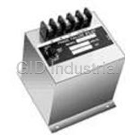
Electromechanical Relay 230VAC 10A SPST-NO Flange Protective Relay 1002X
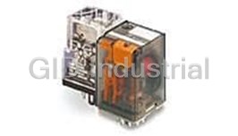
Electromechanical Relay 24VDC 475Ohm 20A 3PDT(35.5x35.6x57)mm Plug-In General Purpose Relay 1-139309...
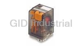
Electromechanical Relay 110VDC 10KOhm 20A 3PDT(35.5x35.6x57)mm Plug-In General Purpose Relay 1-13930...
Electromechanical Relay 220VDC 40KOhm 20A 3PDT(35.5x35.6x57)mm Plug-In General Purpose Relay 1-13930...
Electromechanical Relay 24VDC 475Ohm 20A 3PDT(35.5x35.6x57)mm Plug-In General Purpose Relay 1-139309...
Electromechanical Relay 24VDC 475Ohm 10A 3PDT(35.6x35.5x57)mm Plug-In Industrial Relay 1-1393092-8
Request a Quote

The quote request has been received
Close

Facing challenges or have inquiries? Feel free to contact us!
Call Us +1-469-283-2440
What they say about us
FANTASTIC RESOURCE
One of our top priorities is maintaining our business with precision, and we are constantly looking for affiliates that can help us achieve our goal. With the aid of GID Industrial, our obsolete product management has never been more efficient. They have been a great resource to our company, and have quickly become a go-to supplier on our list!
Bucher Emhart Glass
EXCELLENT SERVICE
With our strict fundamentals and high expectations, we were surprised when we came across GID Industrial and their competitive pricing. When we approached them with our issue, they were incredibly confident in being able to provide us with a seamless solution at the best price for us. GID Industrial quickly understood our needs and provided us with excellent service, as well as fully tested product to ensure what we received would be the right fit for our company.
Fuji
HARD TO FIND A BETTER PROVIDER
Our company provides services to aid in the manufacture of technological products, such as semiconductors and flat panel displays, and often searching for distributors of obsolete product we require can waste time and money. Finding GID Industrial proved to be a great asset to our company, with cost effective solutions and superior knowledge on all of their materials, it’d be hard to find a better provider of obsolete or hard to find products.
Applied Materials
CONSISTENTLY DELIVERS QUALITY SOLUTIONS
Over the years, the equipment used in our company becomes discontinued, but they’re still of great use to us and our customers. Once these products are no longer available through the manufacturer, finding a reliable, quick supplier is a necessity, and luckily for us, GID Industrial has provided the most trustworthy, quality solutions to our obsolete component needs.
Nidec Vamco
TERRIFIC RESOURCE
This company has been a terrific help to us (I work for Trican Well Service) in sourcing the Micron Ram Memory we needed for our Siemens computers. Great service! And great pricing! I know when the product is shipping and when it will arrive, all the way through the ordering process.
Trican Well Service
GO TO SOURCE
When I can't find an obsolete part, I first call GID and they'll come up with my parts every time. Great customer service and follow up as well. Scott emails me from time to time to touch base and see if we're having trouble finding something.....which is often with our 25 yr old equipment.
ConAgra Foods