

 Manufacturers
TE CONNECTIVITY 2-231652-6

Description
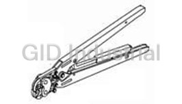
Modular Plug Hand Tool
2-231652-6
Part Number
2-231652-6
Price
Request Quote
Manufacturer
TE CONNECTIVITY
Lead Time
Request Quote
Category
Tools and Supplies » Assembly Tools
Specifications
Manufacturer
TE Connectivity
Manufacturers Part #
2-231652-6
Industry Aliases
2-231652-6
Sub-Category
Electronics Assembly Tools
Brand
AMP
Factory Pack Quantity
1
Datasheet
DDEController?Action=showdoc&DocId=Specification+Or+Standard%7F408-9767%7FH%7Fpdf%7FEnglish%7FENG_SS_408-9767_H.pdf
337 KiB

Extracted Text
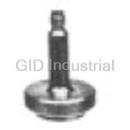
Instruction Sheet Modular Plug Hand Tools (Premium Grade) 231652-[ ] 408-9767 June 2016, Rev S PROPER USE GUIDELINES Cumulative Trauma Disorders can result from the prolonged use of manually powered hand tools. Hand tools are intended for occasional use and low volume applications. A wide selection of powered application equipment for extended-use, production operations is available. 1. INTRODUCTION 2. DESCRIPTION (FIgure1) Modular Plug Hand Tools 231652-[ ] (shown in The die set consists of a nest and an indenter, each Figure 1) are designed to terminate modular plug marked with a color-code dot. The die set is held in the connectors onto stranded or solid, shielded or tool by a single die-holding screw. Each die set is unshielded flat oval cable or round cable. The tool also unique to its purpose, but die sets can be cuts and strips unshielded flat oval cable. Other cable interchanged to accommodate any modular plug. must be prepared by separate tools. Refer to Figure 2. Each tool includes Die Set (853400-[ ]) (see Figure 2), The tool features a wire cutter and flat oval cable except Tool 2-231652-0 which is available without a stripper to prepare unshielded flat oval cable. The tool die set. The die sets are also available separately. handle ensures full crimping. Once engaged, the ratchet will not release until the handles have been All numerical values in this instruction sheet are in NOTE FULLY closed, unless the ratchet release (pawl) is metric units [with U.S. customary units in brackets]. depressed to manually release the ratchet. When Dimensions are in millimeters [and inches]. Figures depressed, the pawl prevents crimping of an i are not drawn to scale. improperly positioned modular plug. Reasons for reissue of this instruction sheet are provided in Section 8, REVISION SUMMARY. DIE SET TOOL PART COLOR DESCRIPTION NUMBER CODE DOT (Modular Plug Type) Nest (Die) 8-Position Line Die Holding Color Code Dot Indenter (Die) Blue (Small Conductor) Screw 2-231652-1† 0-853400-1 Black Color Code Dot Keyed, Non-Keyed Shielded 4-Position 2-231652-3 0-853400-3 Green Handset Ratchet 6-Position 2-231652-6 0-853400-6 Orange Cable Cutter Offset Latch 6-Position 2-231652-7 0-853400-7 Violet Long Body 2-, 4-, 6-Position Line 2-231652-8 0-853400-8 Blue Blue (Small Conductor) 8-Position 3-231652-0† 1-853400-0 White High Performance Flat Oval 8-Position Line Cable 3-231652-5 1-853400-3 Red Blue (Small Conductor) Stripper Non-Keyed Ratchet 8-Position Slimline Release 3-231652-6 1-853400-4 Gray Category 6/6A (Pawl) The BLACK color-coded tool and die set can be used for non-keyed modular plugs; however, the RED color-coded tool and die set are Handle more durable when crimping non-keyed modular plugs. † Includes 2119000-1 JacKnack Tool (408-10326). Figure 2 DO NOT cycle the tool CAUTION without a die in place; The dies bottom before the ratchet releases. This CAUTION otherwise, damage to the feature ensures maximum electrical and tensile ! . stripping blades may occur performance of the crimp. DO NOT re-adjust the ! ratchet. Figure 1 This product is covered by one or more U.S. © 2016 CommScope, Inc. 1 of 6 patents or their foreign equivalents. For patents, see All Rights Reserved www.commscope.com/ProductPatent/ProductPatent.aspx 408-9767 3. CABLE PREPARATION Proceed as follows: Refer to Figure 3, and select the appropriate cable and 3.1. Unshielded Flat Oval Cable (Figure 4) die set for the modular plug being used. 1. Insert cable squarely into CUT slot in tool cable cutter. Squeeze handles until ratchet releases. MODULAR PLUG CABLE DIE SET COLOR 2. Insert trimmed cable into STRIP slot in tool flat POSITION TYPE TYPE STYLE CODE DOT oval cable stripper until cable butts against die cable stop. 2 Line Stranded Flat Oval Blue 3. Close handles to last ratchet stop, but DO NOT Solid release them. Pull cable straight out of tool. Then Handset Flat Oval Green Stranded release tool handles. 4 Line Stranded DO NOT squeeze handles together while pulling NOTE Flat Oval Blue cable out. Rather, with handles closed (but not Blue Solid released) grip head of tool in one hand and cable in i Solid Round the other; then pull cable straight out of tool. Line Blue Stranded Flat Oval 4. Check cable strip length as shown in Figure 4. Blue Solid Flat Oval Blue 3.2. Shielded Flat Oval Cable and Round Cable Offset Latch Solid Flat Oval Orange 6 Prepare the cable according to Application Solid Flat Oval Long Body Specification 114-6016. Violet Unshielded Stranded Round 3.3. High Performance Cable Long Body Stranded Flat Oval Violet Shielded Prepare the cable according to Application Specification 114-6053. Stranded Round DO NOT cut or remove insulation from individual Solid NOTE conductors. This may result in shorted or open Unshielded Flat Oval Stranded terminations within the terminated assembly. i Solid Round Black 8 Blue Solid Flat Oval 4. TERMINATION PROCEDURE Keyed, Before proceeding, make sure that the cable and Stranded Flat Oval Non-Keyed modular plug are compatible, and that cable polarity is correctly maintained for the specific application. Shielded Stranded Round Non-Keyed Stranded Flat Oval Red Before proceeding with high performance modular plugs, refer to 114-6053 for preparation techniques to Stranded ensure high performance levels. Unshielded 8 Solid Refer to Figure 5, and proceed as follows: (High Round White Stranded Performance) Shielded 1. Hold modular plug as shown (locking latch facing Solid UP). Insert cable into modular plug until fully bottomed. Stranded Unshielded 2. Open tool handles. Insert modular plug assembly Solid 8 Round Red fully into die cavity. When using a die set color (Slimline) Stranded coded with green, orange, or blue, make sure that Shielded Solid the modular plug locking latch snaps into position. When using a die set color coded with black, violet, The BLACK color-coded tool and die set can be used for non-keyed or white, make sure that the modular plug bottoms modular plugs; however, the RED color-coded tool and die set are more in the die cavity but the locking latch does not snap durable when crimping non-keyed modular plugs. into position. Standard modular plugs are designed to be used with cable having an outside diameter of 0.89 to 0.99 mm [.035 to .039 in.]. Use blue (small Failure to fully seat the modular plug assembly in CAUTION conductor) modular plugs with cable having an outside diameter of 0.74 to the die cavity will cause the indenter to mis-align 0.86 mm [.029 to .034 in.]. with the internal strain reliefs of the modular plug, Figure 3 ! which may result in damage to the die set. 3. Hold the modular plug in the fully seated position, and squeeze tool handles until ratchet releases. Rev S 2 of 6 408-9767 Figure 4 Figure 5 Rev S 3 of 6 408-9767 When crimping, make sure to hold the modular Once a termination has been made, DO NOT CAUTION NOTE plug in the fully seated position to prevent the re-terminate the modular plug. Replace damaged modular plug from pushing out during the modular plugs with new ones. i ! termination procedure. 4. Depress the modular plug locking latch (if 5. ADJUSTMENTS applicable), and remove terminated modular plug assembly from the tool. 5.1. Changing Die Set 5. Inspect the modular plug assembly for proper 1. Squeeze the tool handles until the ratchet releases. crimp height using a dial indicator or digital indicator 2. Using a small flat blade screwdriver or with needle-point probes. Refer to Figure 6 for a cross-recessed screwdriver, turn the die holding typical terminated modular plug, proper crimp height screw counterclockwise, and remove it. dimension, and required location of the conductors. A visual inspection through the plastic housing of 3. Using the screwdriver, push the die set out of the the modular plug should reveal whether the tool. conductors are within acceptable range. 4. Insert the die set with the color dots facing For specific information concerning inspection NOTE outward as shown in Figure 1. requirements, refer to 114-6016 for standard and 5. Close the tool handles. Re-install the die holding blue (small conductor) modular plugs and 114-6053 i screw. Turn the screw clockwise until it is tight. for high performance modular plugs. 5.2. Adjusting Flat Oval Cable Stripper (Figure 8) Terminated Modular Plug Inspection If the cable jacket is cut too shallow and does not strip (Cross-Section Shown) properly from the conductor bundle or if it is cut too deeply and the conductor insulation is also cut, adjust 6.02±0.13 [.237±.005] Terminal the flat oval cable stripper on the tool according to the following. The die set must be in the tool when adjusting the NOTE flat oval cable stripper. i 1. Close the tool handles until the dies bottom, but A (See Table) B (See Table) Note: Not to Scale DO NOT release the handles. 2. Loosen the two screws that hold the movable CONDUCTOR LOCATION blade assembly. MODULAR PLUG A B TYPE 3. Insert Blade Set-Up Gage 231667-2 (available (Reference Zone) (Preferred) separately and part of Blade Replacement Kit Standard and Conductors 231662-4) or a 1.02 [.040] shim between the stationary 0.00-0.64 [.000-.025] Blue (Small Conductor) Against End of and movable blades. Slide the movable blade against Wire Circuits the gage or shim, and tighten the screws. High Performance 0.00-0.25 [.000-.010] The recommended shim thickness does not Figure 6 NOTE account for a larger than normal conductor insulation. Adjust the blade gap according to Crimp Height Gage 904170-1 is available to be used i specific needs. as a quick verification of acceptable crimp height. Refer to 408-4389 for instructions on using the gage. 5.3. Replacing Flat Oval Cable Stripper Blades (Figure 8) See Figure 7. The gage cannot be used for 4-position handset or 6-position offset modular plugs. If the flat oval cable stripper blades are worn or damaged, replace the fixed blade assembly and movable blade assembly according to the following. Crimp Height 1. Remove the four screws holding both blades in Gage place. Remove the fixed blade assembly and movable blade assembly from the tool. 2. Position the new blades onto the tool with the Modular Plug beveled edges facing inward. (Ref) 3. Install and tighten the screws. Adjust the flat oval cable stripper according to Paragraph 5.2. Figure 7 Rev S 4 of 6 408-9767 DO NOT lubricate surfaces of the die set that CAUTION Adjusting Flat Oval Cable Stripper contact the product. These areas must be kept clean to ensure a usable modular plug assembly. Movable Blade ! Assembly Die Set Must Be Installed in Tool 6.2. Periodic Inspection It is recommended that the following inspections be Blade Set-Up conducted at least once a month by quality control Gage (Ref) personnel. More frequent inspections should be conducted if your work environment, company standards, or amount of tool use indicates the need. A. Visual Inspection Screw 1. Remove the die set from the tool, then remove all (2 Places) lubrication, accumulated film, and debris by immersing the dies and tool head in a mild commercial degreaser. 2. Check for missing or defective pins, rings, or other CAUTION: DO NOT cycle the tool without the die set in place; retaining hardware. Replace parts as necessary. otherwise, damage to the stripping blades may occur. 3. Closely inspect dies for damage, giving special Replacing Blades in Flat Oval Cable Stripper attention to bearing surfaces and surfaces that contact the product. Worn, cracked, pitted, or 6.4 [.25] (Length) chipped indenter or nest surfaces, or other obvious Screw (2 Places) wear or damage to the die set or tool head requires Fixed Blade removal of the affected part from service. Assembly B. Die Closure Inspection Fixed Blade Support Plate The tool and die set is inspected for proper operation Beveled Edges of before shipment. To ensure uniform performance over Blades Face the life of the tool, periodically inspect as follows: Cable Inward 9.7 [.38] (Length) (Ref) 1. Insert a properly stripped cable of appropriate type Screw (2 Places) and size into a sample modular plug. Then insert the unterminated cable and plug into the die cavity. Movable Blade Assembly 2. Squeeze tool handles together slowly, while Movable Blade watching to ensure indenter bottoms against nest. Support Plate 3. Release the handles to open the die set, and remove the terminated modular plug assembly. Figure 8 4. Test the crimp for proper crimp height according to Step 4 in Section 4. If the plug crimp height is 6. MAINTENANCE AND INSPECTION within acceptable limits, lightly lubricate the tool and die set. If the crimp height is not within acceptable Inspect the tool and die set immediately upon arrival at limits, return the tool (with die set) for evaluation your facility and at regularly scheduled intervals (refer to Section 7). thereafter to ensure that they have not been damaged. When not in use, store the tool with the handles closed 7. REPLACEMENT AND REPAIR in a clean, dry area. Customer-replaceable parts are provided in Figure 9. Failure to perform daily maintenance and periodic CAUTION A blade replacement kit and hand tool kits are inspection can cause defective modular plug available separately. A complete inventory should be terminations leading to discontinuities on individual ! stocked and controlled to prevent lost time when wire circuits. replacement of parts is necessary. Order replacement parts through your CommScope account 6.1. Daily Maintenance representative. Foreign particles should be cleaned from the tool using a soft, clean, lint-free cloth or brush. Make sure all pins, rings and other retaining hardware is in place, and that the die set is undamaged. Lightly lubricate all pins, pivot points, and bearing surfaces using a good grade SAE 20 motor oil. DO NOT lubricate excessively. Rev S 5 of 6 408-9767 For tool evaluation and customer repair service, 8. REVISION SUMMARY contact your CommScope account representative. Revisions to this instruction sheet include: • Rebranded to CommScope. • Updated tables in Figures 2 and 9. ITEM PART NUMBER DESCRIPTION QTY PER TOOL 1 993314-1 SCREW, Pan Head (Die Holding) 4-40 x .250 Long 1 2 4-23619-8 PIN, Grooved 2 3 21045-3 RING, Retaining, Crescent 4 4 2-23620-5 PIN, Center, Straight 1 5 21045-6 RING, Retaining, Crescent 2 6 853400-[ ] † DIE SET 1 7 2-231652-0 TOOL ASSEMBLY FRAME (Without Die Set) 1 8 21045-1 RING, Retaining, Crescent 2 9 768522-1 PIN, Handle (Pawl) 2 100 231662-4 BLADE REPLACEMENT KIT 1 † Refer to Figure 2 for cross-reference of tool-to-die set part numbers. Available separately: PART NUMBER DESCRIPTION BLADE REPLACEMENT KIT — Blade Set-Up Gage, 4 Pan Head Screws, 1 Cutter Blade Screw, 5 Wire Cutter Blades, 0-231662-4 5 Fixed Blade Holders, 5 Slider Blade Assemblies HAND TOOL KIT — Carrying Case, Screwdriver, Set of Strip Blades, Cutoff Blade, 2 Support Plates, 4 Pan Head Screws, and 0-231666-9 2119000-1 JacKnack Tool HAND TOOL KIT — Same items as in Kit 231666-9 and: 1-231666-0 Modular Plug Hand Tool and the following Die Sets: 4-Position Line, 6-Position Line, and 8-Position HAND TOOL KIT — Same items as in Kit 231666-9 and: 1-231666-1 Modular Plug Hand Tool and the following Die Sets: 4-Position Line, 6-Position Line, 8-Position, and 4-Position Handset HAND TOOL KIT — Same items as in Kit 231666-9 and: Modular Plug Hand Tool and the following Die Sets: 1-231666-5 4-Position Handset, 4-Position Line,6-Position Line, 8-Position, and 8-Position High Performance Figure 9 Rev S 6 of 6
Frequently asked questions
How does Electronics Finder differ from its competitors?

Is there a warranty for the 2-231652-6?
Which carrier will Electronics Finder use to ship my parts?
Can I buy parts from Electronics Finder if I am outside the USA?
Which payment methods does Electronics Finder accept?
Why buy from GID?

Quality
We are industry veterans who take pride in our work

Protection
Avoid the dangers of risky trading in the gray market

Access
Our network of suppliers is ready and at your disposal

Savings
Maintain legacy systems to prevent costly downtime

Speed
Time is of the essence, and we are respectful of yours
Related Products

Torque Wrenches Are Used To Properly Install Or Disassemble The Connectors 1055419-1
Tool For RF Connectors 1055442-1
Tool For RF Connectors 1055443-1
Insertion Tool For RF Connectors 1055447-1
Insertion Tool For RF Connectors 1055448-1
Assembly Tools, Sma Right Angle Cable Plugs 1055451-1
Request a Quote

The quote request has been received
Close

Facing challenges or have inquiries? Feel free to contact us!
Call Us +1-469-283-2440
What they say about us
FANTASTIC RESOURCE
One of our top priorities is maintaining our business with precision, and we are constantly looking for affiliates that can help us achieve our goal. With the aid of GID Industrial, our obsolete product management has never been more efficient. They have been a great resource to our company, and have quickly become a go-to supplier on our list!
Bucher Emhart Glass
EXCELLENT SERVICE
With our strict fundamentals and high expectations, we were surprised when we came across GID Industrial and their competitive pricing. When we approached them with our issue, they were incredibly confident in being able to provide us with a seamless solution at the best price for us. GID Industrial quickly understood our needs and provided us with excellent service, as well as fully tested product to ensure what we received would be the right fit for our company.
Fuji
HARD TO FIND A BETTER PROVIDER
Our company provides services to aid in the manufacture of technological products, such as semiconductors and flat panel displays, and often searching for distributors of obsolete product we require can waste time and money. Finding GID Industrial proved to be a great asset to our company, with cost effective solutions and superior knowledge on all of their materials, it’d be hard to find a better provider of obsolete or hard to find products.
Applied Materials
CONSISTENTLY DELIVERS QUALITY SOLUTIONS
Over the years, the equipment used in our company becomes discontinued, but they’re still of great use to us and our customers. Once these products are no longer available through the manufacturer, finding a reliable, quick supplier is a necessity, and luckily for us, GID Industrial has provided the most trustworthy, quality solutions to our obsolete component needs.
Nidec Vamco
TERRIFIC RESOURCE
This company has been a terrific help to us (I work for Trican Well Service) in sourcing the Micron Ram Memory we needed for our Siemens computers. Great service! And great pricing! I know when the product is shipping and when it will arrive, all the way through the ordering process.
Trican Well Service
GO TO SOURCE
When I can't find an obsolete part, I first call GID and they'll come up with my parts every time. Great customer service and follow up as well. Scott emails me from time to time to touch base and see if we're having trouble finding something.....which is often with our 25 yr old equipment.
ConAgra Foods