

 Manufacturers
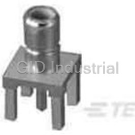
TE CONNECTIVITY 220189-3

Description
BNC Crimping Die For Comm Tool
220189-3
Part Number
220189-3
Price
Request Quote
Manufacturer
TE CONNECTIVITY
Lead Time
Request Quote
Category
Fasteners, Hardware and Fluid Transfer » Hardware Tools
Specifications
Manufacturer
TE Connectivity
Manufacturers Part #
220189-3
Industry Aliases
220189-3
Sub-Category
Hardware Tools
Brand
AMP
Factory Pack Quantity
1
Datasheet
DDEController?Action=showdoc&DocId=Specification+Or+Standard%7F408-2786%7FG%7Fpdf%7FEnglish%7FENG_SS_408-2786_G.pdf
129 KiB

Extracted Text
Instruction Sheet CrimpingDieAssemblies 408--2786 220189-[]and58330-1 03 MAY 11 RevJ PROPERUSEGUIDELINES CumulativeTraumaDisorderscanresultfromtheprolongeduseofmanuallypoweredhandtools.Handtoolsareintendedforoccasionaluseandlowvolume applications.Awide selection ofpowered application equipmentforextended--use,production operationsisavailable. Die Retaining Screws Stationary Jaw Indenter Die PRO--CRIMPER* III Frame Assembly Crimping Die 354940--1 (Ref) Assembly (Ref) Moveable Anvil Die Jaw Center Contact Ferrule Crimping Crimping Chamber Chamber DIEASSEMBLYPARTNUMBER CONNECTORBASEPARTNUMBER 220189--1, 220189--2 227000, 227079, 228980, 228979 220189--3 225395, 225396, 225397, 225398 58330--1 227079 Figure 1 Reasons for reissue are provided in Section 8, 1. INTRODUCTION REVISION SUMMARY. All dimensions in this document are in millimeters NOTE This instruction sheet covers the use and [with inches in brackets]. Figures and Illustrations maintenance of Crimping Die Assemblies listed in are for reference only and are not drawn to scale. i Figure 1. The dies are used in PRO--CRIMPER III Frame Assembly 354940--1 to crimp 50-- and 2. DESCRIPTION 75--Ohm BNC, and 50--Ohm TNC Dual--Crimp Connectors onto various size cable. Refer to Figure 1 Each die assembly consists of an indenter die and an for a list of connectors that are compatible with the anvil die, which when mated form two crimping die assemblies. Refer to Catalog 82074 for additional chambers. The large crimping chamber crimps the product part number information. For part numbers connector ferrule and the small crimping chamber not listed, contact TE Connectivity Product crimps the connector center contact. Each die is held Engineering for recommendations. in the tool by a single screw. See Figure 1. E2011 Tyco Electronics Corporation, a TE Connectivity Ltd. Company TOOLING ASSISTANCE CENTER 1--800--722--1111 This controlled document is subject to change. 1 of 5 All Rights Reserved PRODUCT INFORMATION 1--800--522--6752 For latest revision and Regional Customer Service, *Trademark visit our website at www.te.com LOCB TE Connectivity, TE connectivity (logo), and TE (logo) are trademarks. Other logos, product and/or Company names may be trademarks of their respective owners. 408-2786 3. DIEINSTALLATION Crimping the Center Contact To be sure that the die assembly is properly aligned during installation, proceed as follows: 1. Slide the die assembly into the partially--opened tool jaws. The anvil die must be installed in the movable jaw of the tool and the indenter in the stationary jaw. The center contact crimping chamber must be toward the front of the tool as Center Contact shown in Figure 1. Flange Butt Against Edge 2. Insert, but do not completely tighten, the die of Die retaining screws. 3. Close the tool jaws and carefully align the dies Anvil Die so that the anvil die enters the indenter die. Once the anvil has entered the indenter, place a copper bus bar (1.57+0.05 mm [.062+.002 in.] diameter) into the center contact crimping chamber of the die Stripped Cable assembly. 4. With bus bar in place, close the tool jaws Flange on End of completely. Hold the tool handles together and Cross--Sectional Center Contact tighten the die retaining screws with the View appropriate screwdriver. Edge of Die 4. CRIMPINGPROCEDURE Figure 2 For detailed information on cable selection, cable NOTE strip lengths, and proper assembly of the 4.2. Ferrule (Figure 3) connector, refer to the instructions provided with i the connector. 1. Insert the crimped center contact into the connector body until the cable dielectric butts Select the appropriate die assembly that is against the dielectric inside the connector body. compatible with the connector being used. Proceed The flared braid must fit around the support sleeve as follows: of the connector body. 4.1. CenterContact (Figure 2) Shoulder on 1. Slide the ferrule onto the cable, then strip the Connector cable to the proper dimensions. Body Butts Against 2. Slide center contact onto center conductor of Edge of Die cable; then insert contact assembly into the center contact crimping chamber of the anvil die. See Figure 2. Make sure that the flange on the end of the NOTE center contact butts against the edge of the die. Ferrule in Refer to the cross--sectional view in Figure 2. i Crimping Chamber on Anvil 3. Crimp the center contact by holding the cable in Die place; then close the tool handles until the ratchet releases. 4. Remove the crimped center contact assembly Figure 3 from the crimping dies. 2 of 5 RevJ 408-2786 2. Slide the ferrule forward over the braid until the 4. When the dies are not in use, mate and store ferrule butts against the shoulder on the connector them in a clean, dry area. body. 6.2. PeriodicInspections 3. Place the ferrule in the ferrule crimping chamber Regular inspections should be performed by quality of the anvil die so that the shoulder on the control personnel. A record of scheduled inspections connector body butts against the edge of the die. should remain with the dies and/or be supplied to SeeFigure3. supervisory personnel responsible for the dies. 4. Holding the assembly in place, close the tool Though recommendations call for at least one handles until the ratchet releases. inspection per month, the inspection frequency should be based on amount of use, working conditions, 5. Remove crimped assembly from the crimping operator training and skill, and established company dies. standards. These inspections should be performed in the following sequence: 5. CRIMPHEIGHTADJUSTMENT (Figure 4) Screwdriver The tool frame assembly ratchet mechanism features an adjustment wheel with numbered settings. If the crimp height is not acceptable, adjust the ratchet as follows: 1. Remove the lockscrew from the ratchet adjustment wheel. 2. With a screwdriver, adjust the ratchet wheel Ratchet from the opposite side of the tool. Adjustment Wheel 3. Observe the ratchet adjustment wheel. If a tighter crimp is required, rotate the adjustment wheel COUNTERCLOCKWISE to a higher--numbered setting. If a looser crimp is Lockscrew (Typ) required, rotate the adjustment wheel CLOCKWISE to a lower--numbered setting. Figure 4 4. Replace the lockscrew. A. VisualInspection 5. Make a sample crimp and measure the crimp height. If the crimp height is acceptable, secure the 1. Remove all lubrication and accumulated film by lockscrew. If the dimension is unacceptable, immersing the dies in a suitable commercial remove lockscrew and continue to adjust the degreaser. ratchet, and again measure a sample crimp. 2. Make certain all die retaining screws and die components are in place and secured. If replacements are necessary, refer to Section 7, 6. MAINTENANCEANDINSPECTION REPLACEMENT. 6.1. DailyMaintenance 3. Inspect the crimp area for flattened, chipped, worn, cracked, or broken areas. If damage is It is recommended that each operator of the tool with evident, the dies must be replaced (see Section 7, the die assembly be made aware of, and responsible REPLACEMENT). for, the following four steps of daily maintenance: 1. Remove dust, moisture, and other contaminants B. GagingtheCrimpingChamber with a clean, soft brush, or a clean, soft, lint--free This inspection requires the use of a plug gage cloth. Do NOT use any objects that could damage conforming to the diameters provided in Figure 5. TE the dies or tool. does not manufacture, or market, these gages. 2. Make sure that the proper die retaining screws Proceed as follows: are in place and secured. 1. Mate the dies until it is evident that they have 3. Make certain that all surfaces are protected with bottomed. Hold the dies in this position by holding a THIN coat of any good SAE 20 motor oil. the tool handles closed with moderate pressure. RevJ 3 of 5 408-2786 2. Align the GO element of the gage with the 7. REPLACEMENT crimping chamber. Push the element straight into Parts listed in Figure 6 are customer--replaceable. A the chamber without using force. The GO element complete inventory can be stocked and controlled to must pass completely through the crimping prevent lost time when replacement of parts is neces- chamber as shown in Figure 5. sary. Order replacements through your local TE Representative, or call 1--800--526--5142, or send a 3. Align the NO--GO element with the crimping facsimile of your purchase order to 1--717--986--7605, chamber and try to insert it straight into the or write to: chamber. The NO--GO element may start entry but must not pass completely through. See Figure 5. CUSTOMER SERVICE (38--35) TYCO ELECTRONICS CORPORATION P.O. BOX 3608 If the crimping chambers conform to the gage HARRISBURG, PA 17105--3608 inspection, the dies are considered dimensionally correct and should be lubricated with a thin coat of any good SAE 20 motor oil. If not, the dies must be replaced before returning them to service. 8. REVISIONSUMMARY S Updated document to corporate requirements. For additional information concerning the use of the plug gage, refer to Instruction Sheet 408--7424. Suggested Plug GageDesign for Suggested Plug GageDesign W GO CenterContactCrimping Chamber NO--GO GO forFerruleCrimping Chamber Dia Dia Dia NO--GO Dia R Crimping “GO” element must Chamber pass completely through the die closure. “NO--GO” element may enter partially, but must not pass completely through the die closure. GO Element NO--GO Element GAGEELEMENTDIAMETER(mm[in.]) CRIMPING CHAMBER D DIIE EA AS SS SE EM MB BL LY Y CENTERCONTACT FERRULE PARTNO. RADIUS WIDTH GO NO--GO GO NO--GO ‘‘R”(Max) ‘‘W”(Max) 1.207--1.214 1.359--1.367 5.156--5.164 5.408--5.410 2.51 5.03 220189--1 [.0475--.0478] [.0535--.0538] [.2030--.2033] [.2129--.2130] [.099] [.198] 1.054--1.062 1.181--1.189 5.969--5.977 6.220--6.223 2.92 5.84 220189--2 [.0415--.0418] [.0465--.0468] [.2350--.2353 [.2449--.2450] [.115] [.230] 1.925--1.928 1.984--1.986 5.405--5.408 5.667--5.669 2.64 5.28 220189--3 [.0758--.0759] [.0781--.0782] [.2128--.2129] [.2231--.2232] [.104] [.208] 1.029--1.036 1.181--1.189 4.191--4.199 4.442--4.445 2.03 4.06 58330--1 [.0405--.0408] [.0465--.0468] [.1650--.1653] [.1749--.1750] [.080] [.160] Figure 5 4 of 5 RevJ 408-2786 30.48 mm 11.89 mm [1.20 in.] [.468 in.] 2 34.80 mm [1.37 in.] 1 WEIGHT: 227g[8oz] CUSTOMER--REPLACEABLEPARTS DIEASSEMBLY ANVIL INDENTER PARTNO. (Item1) (Item2) 220189--1 310498--2 310497--2 220189--2 310498--4 310497--4 220189--3 310567--1 310568--1 58330--1 313764--1 313763--1 Figure 6 RevJ 5 of 5
Frequently asked questions
How does Electronics Finder differ from its competitors?

Is there a warranty for the 220189-3?
Which carrier will Electronics Finder use to ship my parts?
Can I buy parts from Electronics Finder if I am outside the USA?
Which payment methods does Electronics Finder accept?
Why buy from GID?

Quality
We are industry veterans who take pride in our work

Protection
Avoid the dangers of risky trading in the gray market

Access
Our network of suppliers is ready and at your disposal

Savings
Maintain legacy systems to prevent costly downtime

Speed
Time is of the essence, and we are respectful of yours
Related Products
Crimpers TOOL 1055236-1
Mini Torque Wrenches 1055258-1

Wrenches 2098 0351 54 1055276-1
Hand Tools CABLE BENDER 1055479-1
Connector Accessories Crimp Assembly Kit 1055779-1
Crimpers TOOL 1055835-1
Request a Quote

The quote request has been received
Close

Facing challenges or have inquiries? Feel free to contact us!
Call Us +1-469-283-2440
What they say about us
FANTASTIC RESOURCE
One of our top priorities is maintaining our business with precision, and we are constantly looking for affiliates that can help us achieve our goal. With the aid of GID Industrial, our obsolete product management has never been more efficient. They have been a great resource to our company, and have quickly become a go-to supplier on our list!
Bucher Emhart Glass
EXCELLENT SERVICE
With our strict fundamentals and high expectations, we were surprised when we came across GID Industrial and their competitive pricing. When we approached them with our issue, they were incredibly confident in being able to provide us with a seamless solution at the best price for us. GID Industrial quickly understood our needs and provided us with excellent service, as well as fully tested product to ensure what we received would be the right fit for our company.
Fuji
HARD TO FIND A BETTER PROVIDER
Our company provides services to aid in the manufacture of technological products, such as semiconductors and flat panel displays, and often searching for distributors of obsolete product we require can waste time and money. Finding GID Industrial proved to be a great asset to our company, with cost effective solutions and superior knowledge on all of their materials, it’d be hard to find a better provider of obsolete or hard to find products.
Applied Materials
CONSISTENTLY DELIVERS QUALITY SOLUTIONS
Over the years, the equipment used in our company becomes discontinued, but they’re still of great use to us and our customers. Once these products are no longer available through the manufacturer, finding a reliable, quick supplier is a necessity, and luckily for us, GID Industrial has provided the most trustworthy, quality solutions to our obsolete component needs.
Nidec Vamco
TERRIFIC RESOURCE
This company has been a terrific help to us (I work for Trican Well Service) in sourcing the Micron Ram Memory we needed for our Siemens computers. Great service! And great pricing! I know when the product is shipping and when it will arrive, all the way through the ordering process.
Trican Well Service
GO TO SOURCE
When I can't find an obsolete part, I first call GID and they'll come up with my parts every time. Great customer service and follow up as well. Scott emails me from time to time to touch base and see if we're having trouble finding something.....which is often with our 25 yr old equipment.
ConAgra Foods