

 Manufacturers
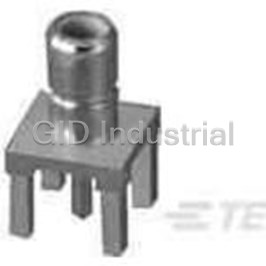
TE CONNECTIVITY 231880-1

Description
Champ Portable Hand Operated Tool Mult-Insertion
231880-1
Part Number
231880-1
Price
Request Quote
Manufacturer
TE CONNECTIVITY
Lead Time
Request Quote
Category
Fasteners, Hardware and Fluid Transfer » Hardware Tools
Specifications
Manufacturer
TE Connectivity
Manufacturers Part #
231880-1
Industry Aliases
231880-1
Sub-Category
Hardware Tools
Brand
AMP
Factory Pack Quantity
1
Datasheet
DDEController?Action=showdoc&DocId=Specification+Or+Standard%7F408-9412%7FB%7Fpdf%7FEnglish%7FENG_SS_408-9412_B.pdf
1971 KiB

Extracted Text
Instruction Sheet CHAMP* Portable Hand Operated Tool Mult-Insertion (MI-1) 408-9412 No. 231880-1 (64-Position) 04 FEB 11 Rev B PROPER USE GUIDELINES Cumulative Trauma Disorders can result from the prolonged use of manually powered hand tools. Hand tools are intended for occasional use and low volume applications. A wide selection of powered application equipment for extended-use, production operations is available. Rear Combs Locking Latch Catch Handle Wire Comb Support Locking Latch Inserter Assembly (Wire Inserter with Wire Stuffer and Inserter Pin) Handle Stop Handle Stop Baseplate Shear Plates Spring Lock Handle Connector Support Thumbscrew Note that Tool 231880-1 is shown exploded for clarity. Figure 1 1. INTRODUCTION 2. DESCRIPTION (FIgure 1) The CHAMP Portable Hand Operated Tool 231880-1 The MI-1 hand tool 231880-1 contains a fixed wire (MI-1) is designed to terminate 64-position CHAMP comb feature and will produce a 90 degree (right- connectors using the displacement crimp technique. It angle) cable dress. The features of the hand tool are can also terminate 14-, 24-, and 36-position CHAMP as follows: connectors without any modification or conversion. In Base Plate - Supports functional components of the its marketed form, tool 231880-1 is not capable of tool. The base plate can be secured to the work terminating 50-position CHAMP connectors. It can be bench. converted to terminate 50-position connectors by using Inserter Assembly 229694-7; see Paragraph 10. Handles - Retain wire stuffers/inserters and provide insertion force. Stops on handles prevent over- All dimensions on this sheet are in millimeters [with NOTE insertion during the terminating process. inch equivalents in brackets]. Figures and illustrations are for identification only and are not Connector Support - Holds connector in proper i drawn to scale. position and provides surface (shear plates) for cutting off excess wire. Reasons for reissue of this sheet are provided in Section 13, REVISION SUMMARY. Spring Lock - Affords positive lock when connector support is in the UP position. ©2011 Tyco Electronics Corporation, Berwyn, PA TOOLING ASSISTANCE CENTER 1-800-722-1111 This controlled document is subject to change. 1 of 8 All Rights Reserved PRODUCT INFORMATION 1-800-522-6752 For latest revision and Regional Customer Service, TE logo and Tyco Electronics are trademarks. visit our website at www.tycoelectronics.com *Trademark. Other products, logos, and company names might be trademarks of their respective owners. LOC B 408-9412 Thumbscrew - Secures connector to the connector support. 203.2 [8.000] Approx Wire Combs - Consist of two rear combs and two front combs. The combs separate and hold wires that are laced into the tool. Wire Comb Supports - Support wire combs and locking latch. Cable Clamp - Holds cable in position on the tool during lacing procedure. Locking Latch - Holds wire comb supports together during termination of wires. Inserters and Wire Stuffers - Cuts and simultaneously inserts wires between contact slots. Preparation of Cable 3. POSITIONING TOOL FOR USE (Five Color Groups Shown) Select a sturdy work bench that is a convenient height for the operator. Position the tool on the work bench: No standard code exists for 64-position assemblies. make sure there is sufficient space at the back of the tool to permit handling of the cable bundle, and make WIRE sure tool handles can open fully. Secure the base plate to the work bench. Make certain the work area is INSULATION WIRE SIZE CONDUCTOR DIAMETER well illuminated, and that the area around the tool is 2 TYPE mm [AWG] (Max.) kept clear for operation of the handles. 0.13-0.3 [26-22] Solid 4. CABLE PREPARATION (FIgure 2) 1.14 [.045] 0.09-0.3 [28-22] Stranded (7 Strands) The connector contacts are designed to accept No. Figure 2 26-22 AWG solid conductor wires or 28-22 AWG stranded (7-strand only) conductor wires. A maximum 5. TERMINATING PROCEDURE insulation diameter of 1.14 [.045] is acceptable for soft insulation, such as pvc or polyethylene. 5.1. Placing Wires and Connector in Tool The following procedure has been prepared for NOTE 1. Open tool handles fully. Push on left side of standard color-coded wires. The same method of locking latch until it snaps open, then push on right operation will apply for nonstandard color-coded i side to open latch completely. Refer to Figure 1. wires - however, the wire groups MUST be defined in some other way. 2. Rotate both wire comb supports outward and move connector support down. The tool is now Proceed as follows: ready to receive the connector and wires. 1. Remove approximately 203.20 [8.000] of 3. Loosen thumbscrew by rotating it sheathing from the cable end. Do NOT nick or cut COUNTERCLOCKWISE several turns. the insulation of the individual wires. 4. Select the appropriate plug or receptacle If using connector with short tapered cover, slit NOTE connector size for the application. Align connector cable sheathing back 25.4 [1.000] - then fold with FRONT of connector support - make sure sheathing back over itself before placing cable in i connector is oriented properly by use of contact tool. position numbers: LOW number positions are to the 2. Separate wires into color groups (predominantly LEFT. Insert connector between shear plates and white in one group, predominantly red in one group, into connector support until it bottoms. etc.) 5. Turn thumbscrew CLOCKWISE until connector is 3. Wrap a piece of wire around each group to keep securely held. the groups separated. 6. Open the cable clamp and position cable so that the sheathing extends at least 12.7 [.500] above the base plate. Hold cable in position and close cable clamp. See Figure 3. Rev B 2 of 8 408-9412 5. Look into sides of both wire comb supports to Place Half of Wire Bundle Over check alignment of wires. Each conductor must be Cable Secured Each End of Wire Comb Support aligned with a single contact. on Baseplate 6. Raise tool handles until the stops on the handles Typical Lacing of butt against each other (these are two-handed Wires into Combs tools, and the handle stops must bottom). This shears all wire ends and fully inserts all wires. 7. Remove sheared wire ends from combs. Lower the tool handles. 8. Loosen thumbscrew by turning it Tool COUNTERCLOCKWISE. Handle (Typ) 9. Open locking latch and rotate wire comb supports Center downward. of Tool 10. Open cable clamp. Slide terminated connector Typical Connector Inserted and straight out of connector support. Fully Bottomed in Connector Support 11. Inspect all terminations as described in Paragraph 6. Figure 3 Locking Latch 7. Pull first group of wires forward and remove piece Wire Comb of wire installed in preparing the cable (Step 3 of Supports Paragraph 4). Separate wires by tracer and body color (ring and tip). Place ring wires to the LEFT and tip wires to the RIGHT. Wires 8. Lace wires into combs, starting towards the Retained center. Take wire from one side (LEFT or RIGHT) Connector in Wire and lace wire through rear comb teeth and into Support Combs corresponding position in front comb teeth. While keeping wire taut, bend wire under front comb and, Wire Stuffers when lacing on tool, around inside of wire comb supports. See Figure 3. 9. Take mating wire from opposite side of tool (lacing fixture) and lace it through combs in same manner. Visually check to make sure wires are properly laced through combs. 10. Repeat Steps 8 and 9 until half of the wire bundle is laced into the combs. After bending first Wire Wire Stuffer/ half of wire bundle around inside of wire comb Inserter Inserter supports toward center of the tool), change direction (Typ 2 and bend second half of wire bundle around outside Places) of wire comb supports, or towards tool handles. Typical Tool Closed and Ready to Terminate in Connector. 5.2. Tool Operation (Figure 4) 1. Check to be sure all wires are parallel in the combs. Make sure connector is bottomed in Figure 4 connector support. 6. INSPECTION OF TERMINATIONS 2. Raise connector support to vertical position. Visually inspect the wire terminations in the connector 3. Be careful that the wires remain in the combs. for the following: Raise one wire comb support to a vertical position and, while holding it in place, raise other wire comb 1. Make certain wire is inserted evenly so that the support to the vertical position. insulation is below the “V” shaped lead-in on both the contact slot and the strain relief slot. See 4. Hook locking latch onto RIGHT wire comb Figure 5. support. Press on LEFT side of locking latch until it is secure. Rev B 3 of 8 408-9412 The quantity-per-tool column indicates the number of each item required for each tool. The recommended Inspection Features spares column indicates the quantity of each in the column required to maintain up to 10 tools for a period 0.38 [.015] Max Conductor Exposure of one year under normal circumstances. A complete inventory should be stocked and controlled to prevent All Wires Below lost time when replacement of parts is necessary. Lead-In Additional tools or replacement parts can be ordered through your Tyco Electronics Representative, or call 50% Min 1-800-526-5142, or send a facsimile of your purchase order to 1-717-986-7605, or write to: Acceptable Deformation - Slot Must Remain Parallel CUSTOMER SERVICE (038-035) Wire in Wire TYCO ELECTRONICS CORPORATION Contact Below PO BOX 3608 Slot Lead-In HARRISBURG PA 17105-3608 Tools may also be returned for evaluation and repair. Strain For tool repair service, contact a Tyco Electronics Relief Representative at 1-800-526-5136. Slot 8. DAILY MAINTENANCE Wire in Both Each operator of the tool should be made aware of - Slots and responsible for - the following steps of daily maintenance. 1. Clean the tool with a soft-bristle brush and/or soft, Figure 5 clean cloth. Do NOT use any type of solvent to clean the tool. 2. Check that all wires have been sheared (if 2. Lubricate pivot points in the center of the tool with applicable) to the proper length (extends at least a few drops of light machine oil. Apply a thin coat of 50% of the distance between the contact slot and LUBRIPLATE{, material or equivalent, to sides of the housing), and not more than 0.38 [.015] the insert. Do NOT lubricate excessively. maximum conductor exposure. 3. Frequently inspect tool for wear or other damage. 3. Check that the insulation is NOT cut in any area If required, replace parts in accordance with the other than the slot insertion area. information provided in Paragraph 9, REPLACING 4. Check to be sure the contacts are NOT deformed WORN OR DAMAGED PARTS. or crushed. 4. When NOT in use, store the tool in a clean, dry 5. Make certain the conductors have NOT been cut area with a connector in the connector support, and above the strain relief slot in the contacts. the tool handles in the closed position. If any of the wires are NOT properly terminated, re- NOTE 9. REPLACING WORN OR DAMAGED PARTS insert them using the T-Handle Insertion Tool 229384-1. Instruction Sheet 408-7558 for use with This section covers parts replacement of those i the tool is packaged with the tool. recommended spares listed in the parts list which require detailed procedures for removal, installation, 7. TOOL INSPECTION and alignment. Refer to Figure 6 and other figures referenced throughout this instruction sheet for CHAMP MI-1 Hand Tool 231880-1 should be assistance. inspected with the information provided in Figure 6. It is recommended that the tool be inspected During parts replacement, use SCREWLOCK‡ NOTE immediately upon its arrival at your facility, and at SEALANT (Part No. 23419-4) or equivalent, on all regularly scheduled intervals, to ensure that the tool screw retention threads. i has not been damaged during handling. The parts listed in Figure 6 are customer replaceable parts. The item number column has been included to provide a reference throughout the text; it is not to be used when ordering parts. To order parts, use the part ‡ Trademark of Locktite Corporation, Newington, CT number and description. Rev B 4 of 8 408-9412 9.1. Cable Clamp (Using Old Style) 3. Position new wire stuffer (Parts List, Figure 6) into inserter and align the holes. Follow these steps if tool has metal cable clamp: 4. Again, support inserter on solid, flat surface. 1. Fully open the tool. Then, insert two new inserter pins (Parts List, Figure 6). 2. .Drive slotted spring pin back far enough to remove the old cable clamp. 5. Unlatch wire comb supports, lower connector support and insert connector into connector support 3. Position new cable clamp and drive slotted spring until it bottoms. Tighten thumbscrew. Raise pin back into place. connector support and wire combs support to the 9.2. Wire Combs vertical position. Secure with locking latch If misalignment of the wires dictates comb adjustment, 6. Operate the respective tool handle several times proceed as follows: to assure proper alignment of wire stuffer with contacts. If alignment is incorrect, adjust the inserter 1. Loosen the screws securing the rear combs. as described in Paragraph 9.5. Raise the wire comb support to the vertical position. 9.5. Inserters 2. While looking into the side of the tool, align the comb with the shear plate and tighten the rear comb The wire inserters are part of the Inserter Assembly screws. and can be ordered separately. See Parts List, Figure 6; refer to Figure 4 for the location of the wire 3. Loosen screws securing the front combs and inserters. The procedure herein applies to both sides align front combs with rear combs. Then tighten of the tool. Note that it may NOT be necessary to screws securing front combs. replace both inserters. If the replacement of both is 9.3. Shear Plates required on a single tool, do NOT remove both at the same time. Never attempt to re-face the shear plates. This will CAUTION destroy the flatness required for shearing all the A. Inserter Replacement wires. ! 1. With tool fully opened, remove the two screws and two flat washers used to secure the inserter assembly to handle. Remove the inserter assembly. Proceed as follows: 2. If inserter is being replaced with a new one (Parts 1. With tool handles and wire comb supports fully List, Figure 6), check wire stuffer for damage. If wire opened, remove the two screws attaching the shear stuffers are not damaged, remove them and place plate to the connector support. them in the new inserters, as described in 2. Position new shear plate on connector support Paragraph 9.4. The same procedure applies if a against the stop and tighten the two screws. new wire stuffer must be installed. ALWAYS use new inserter pins. 3. With connector support open, push down and back on shear plate to seat it on shoulder of 3. Position inserter on handle against locating block. connector support. Hold shear plate in position and Push the inserter down against the locating block tighten the two screws. (Figure 7) and back against the handle. Tighten the two screws. The inserter is now aligned. 4. If opposite shear plate is to be replaced, repeat this procedure. Refer to Paragraph 10 for tool adjustment. 9.4. Wire Stuffers The wire stuffers are part of the Inserter Assembly and can be ordered separately. See Parts List, Figure 6; refer to Figure 4 for location of the wire stuffers. The procedure herein applies to both sides of the tool. It is NOT necessary to remove inserters from the tool. Proceed as follows: 1. With tool handles opened and wire comb supports latched in vertical position, support inserter on a flat surface and, using a drift punch, remove the two inserter pins securing the wire stuffer. 2. Remove wire stuffer from inserter. Rev B 5 of 8 408-9412 Approximate weight with Carrying Case 3.85 kg [8 lb. 5 oz.] 4.19.10 [16.50] 114.30 [4.500] 1.01.6 [4.000] REPLACEMENT PARTS ITEM PART NUMBER DESCRIPTION QTY PER TOOL RECOMMENDED SPARES 1 229622-1 CLAMP, Cable 1 2 2 231873-1 PLATE, Shear 2 2 3 229399-2 COMB, Front 2 2 4 229406-2 COMB, Rear 2 2 7 231879-1 ASSEMBLY, Inserter 2 2 -- 2318678-1• INSERTER, Standard 2 2 -- 230037-1• STUFFER, Standard 2 2 -- 229405-1• PIN, Inserter 4 4 8 229403-1 SPRING, Lock 1 0 • Part of inserter assembly but can be ordered separately Figure 6 Rev B 6 of 8 408-9412 a slight, even drag is apparent - then hold the Inserter Assembly backup plate in position and tighten TOP and BOTTOM setscrews until slight outward pressure is detected. Release pressure on the backup plate and secure TOP and BOTTOM screws. 5. Again, check for slight drag on inserter. If drag is not even, alternately adjust both the TOP and BOTTOM screws, and setscrews, until proper adjustment is obtained. Screw 6. Repeat this procedure for opposite side, if (2) necessary. 7. Terminate several connectors and inspect the terminations. The tool is ready for use when each termination meets the requirements specified in Paragraph 6, INSPECTION OF TERMINATIONS. Locating Block (Do NOT Loosen) Top Setscrew Figure 7 Top Screw B. Inserter Alignment (If Locating Block is Loose or Missing) Screw 1. Raise connector support to vertical position and Wire (2) insert connector into the connector support until it Comb bottoms. Tighten thumbscrew. Raise wire comb (2 Typ) supports to the vertical position. Secure with locking latch. 2. Loosen the screws that secure the back-up plates approximately one turn (see Figure 8). 3. Using caution, raise tool handle until new inserter begins to enter the connector. Then, move inserter up or down to align wire stuffer with contacts. When certain that the wire stuffers have aligned with the Back-Up contacts, close tool handles fully and tighten Plate Bottom screws. Screw 4. If opposite wire inserter is to be replaced, repeat replacement and alignment procedures. 10. TOOL ADJUSTMENT FOR PROPER WIRE CUTTING Bottom Wire-Comb Setscrew Support Proceed as follows: 1. Raise the connector support and then the wire comb supports to the vertical position. Secure with locking latch. 2. Slowly raise the handles - if inserter binds or has Figure 8 excessive drag - STOP. Re-open handles and adjust backup plate as stated in Step 3. Do NOT 11. TROUBLESHOOTING (FIgure 9) force handles closed. Use Figure 9 to assist in isolating troubles. The figure 3. Lower handles. Grip connector support and wire lists the troubles, the possible cause, and the remedy comb support with one hand and release locking for correcting the situation. latch. Now, loosen TOP screw and setscrew, and BOTTOM screw and setscrew securing backup plate to wire comb support. See Figure 8. 4. Move inserter (handle) in and out of shear plate and, simultaneously, squeeze the backup plate until Rev B 7 of 8 408-9412 TROUBLESHOOTING TROUBLE POSSIBLE CAUSE REMEDY Inserter Misalignment Refer to Section 9.5 Combs Misalignment Refer to Section 9.2 Crushing Contacts Wire Size Not Within Tolerance Refer to Section 4 for Specification Make Sure Connector is Bottomed Against the Stop; Connector Not Properly Seated on Connector Holder Be Sure Thumbscrew is Tightened. Tool Not Properly Adjusted Refer to Section 9 Cutting Improperly Inserter Cutting edge Damaged Replace Inserters (See Section 9.5) Tool Not Properly Cleaned Clean the Tool as described in Section 8 For insulation less than 0.89 [.035 in.] in Diameter, Wires Not Held in Combs Wire Insulation Diameter Too Small use (two) small Wire Combs P/N 231619-3. See Section 9.2. Figure 9 12. CONVERTING TOOLS 2. Replace the inserter assemblies with inserter assemblies for 50-position connectors, part no. Although tool 231880-1 is designed to terminate 64- 229694-7. Make sure the inserter assemblies are position connectors and can terminate 14-, 24-, and butted firmly against the handles and the locating 36-position connectors without modification or blocks. See Inserter Replacement procedure, conversion, it can be converted to terminate 50- Subparagraph 9.5). position connectors by using two inserter assemblies, no. 229694-7. Once converted, it will terminate 14- Do NOT disturb the setting of the locating blocks. NOTE through 50-position connectors. Their positions are pre-set during the final assembly of the tool. i To convert the tool for terminating 50-position connectors, proceed as follows: Upon completion of the above procedure, the tool is 1. Remove the two inserter assemblies that have capable of terminating 14- through 50-position been previously installed on the tool. Refer to the connectors. Parts List, Figure 6. 13. REVISION SUMMARY Since the previous release of this instruction sheet, the TE logo has been applied. Rev B 8 of 8
Frequently asked questions
How does Electronics Finder differ from its competitors?

Is there a warranty for the 231880-1?
Which carrier will Electronics Finder use to ship my parts?
Can I buy parts from Electronics Finder if I am outside the USA?
Which payment methods does Electronics Finder accept?
Why buy from GID?

Quality
We are industry veterans who take pride in our work

Protection
Avoid the dangers of risky trading in the gray market

Access
Our network of suppliers is ready and at your disposal

Savings
Maintain legacy systems to prevent costly downtime

Speed
Time is of the essence, and we are respectful of yours
Related Products
Crimpers TOOL 1055236-1
Mini Torque Wrenches 1055258-1

Wrenches 2098 0351 54 1055276-1
Hand Tools CABLE BENDER 1055479-1
Connector Accessories Crimp Assembly Kit 1055779-1
Crimpers TOOL 1055835-1
Request a Quote

The quote request has been received
Close

Facing challenges or have inquiries? Feel free to contact us!
Call Us +1-469-283-2440
What they say about us
FANTASTIC RESOURCE
One of our top priorities is maintaining our business with precision, and we are constantly looking for affiliates that can help us achieve our goal. With the aid of GID Industrial, our obsolete product management has never been more efficient. They have been a great resource to our company, and have quickly become a go-to supplier on our list!
Bucher Emhart Glass
EXCELLENT SERVICE
With our strict fundamentals and high expectations, we were surprised when we came across GID Industrial and their competitive pricing. When we approached them with our issue, they were incredibly confident in being able to provide us with a seamless solution at the best price for us. GID Industrial quickly understood our needs and provided us with excellent service, as well as fully tested product to ensure what we received would be the right fit for our company.
Fuji
HARD TO FIND A BETTER PROVIDER
Our company provides services to aid in the manufacture of technological products, such as semiconductors and flat panel displays, and often searching for distributors of obsolete product we require can waste time and money. Finding GID Industrial proved to be a great asset to our company, with cost effective solutions and superior knowledge on all of their materials, it’d be hard to find a better provider of obsolete or hard to find products.
Applied Materials
CONSISTENTLY DELIVERS QUALITY SOLUTIONS
Over the years, the equipment used in our company becomes discontinued, but they’re still of great use to us and our customers. Once these products are no longer available through the manufacturer, finding a reliable, quick supplier is a necessity, and luckily for us, GID Industrial has provided the most trustworthy, quality solutions to our obsolete component needs.
Nidec Vamco
TERRIFIC RESOURCE
This company has been a terrific help to us (I work for Trican Well Service) in sourcing the Micron Ram Memory we needed for our Siemens computers. Great service! And great pricing! I know when the product is shipping and when it will arrive, all the way through the ordering process.
Trican Well Service
GO TO SOURCE
When I can't find an obsolete part, I first call GID and they'll come up with my parts every time. Great customer service and follow up as well. Scott emails me from time to time to touch base and see if we're having trouble finding something.....which is often with our 25 yr old equipment.
ConAgra Foods