

 Manufacturers
TE CONNECTIVITY 354687-3
Description
Signal Pin Contact Repair Kit
354687-3
Part Number
354687-3
Price
Request Quote
Manufacturer
TE CONNECTIVITY
Lead Time
Request Quote
Category
Fasteners, Hardware and Fluid Transfer » Hardware Tools
Specifications
Manufacturer
TE Connectivity
Manufacturers Part #
354687-3
Industry Aliases
354687-3
Sub-Category
Hardware Tools
Brand
AMP
Factory Pack Quantity
1
Datasheet
DDEController?Action=showdoc&DocId=Specification+Or+Standard%7F408-9979%7FD%7Fpdf%7FEnglish%7FENG_SS_408-9979_D.pdf
97 KiB

Extracted Text
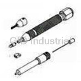
Instruction Sheet SignalPinContactRepairKits 354687-1, -2,and -3 408--9979 ForZ-PACK*Connectors 19FEB 10 RevD PROPERUSEGUIDELINES CumulativeTraumaDisorderscanresultfromtheprolongeduseofmanuallypoweredhandtools.Handtoolsareintendedforoccasionaluseandlowvolume applications.Awideselectionofpoweredapplicationequipmentforextended--use,productionoperationsisavailable. pin contact tail and reinforces it while the tool pushes Contact Replacement Insertion Tool the signal pin contact out. Tool 380392--8 Assembly 354995--1 The extraction tool assembly has two positions for the signal pin contact tip—BACK or INSIDE the pin support tube and FORWARD or BEYOND the pin support tube. The tool pin tip has a concave surface Replacement to aid in positioning the tool over the contact and to Setscrew maintain its location during the removal process. Pin Assembly 1--22642--9 354994--1 The tip of the insertion tool assembly is a T--shaped Tool steel section. It has a larger, flat back section, a Spacer Tip narrow, ribbed front section, and a slot between the (See Table) ribs. Pusher 679037--1 3. USINGTHEREPAIRKIT Pin Support 3.1. ContactRemoval Tube Extraction Tool 1. Assemble the pusher (PN 679037--1) with the Assembly 354996--1 setscrew onto the contact replacement tool. 2. Snap the extraction tool assembly into the Z--PACK REPAIRKIT SPACER contact replacement tool. CONNECTORTYPE 3. Locate the rear of the signal pin contact to be 354687--1 2mmHMandFB 679043--1 removed. 354687--2 HS36-- and10--Row 679043--2 4. Place the spacer over the signal pin contact tail 354687--3 HM12--Row 679043--3 (for mid--plane/long--tail product). Figure 1 If the repair is being made prior to assembling the NOTE connector housing, use the higher surface of the spacer. If the repair is being made after 1. INTRODUCTION i assembling the rear housing, use the lower Signal Pin Repair Kits 354687--1, --2, and --3 are used surface of the spacer. to insert and extract signal pin contacts from Z--PACK connectors. See Figure 1. 5. Depending on the location of the tip of the signal pin contact in relation to the board (or spacer) Parts shown in Figure 1 are also available NOTE surface, position the tool tip as follows: separately. —If the tip of the signal pin contact is flush with i the board (or spacer) surface, position the tool tip in the FORWARD position (refer to Figure 2) and place the tool tip on the signal pin contact tip. The Reasons for reissue of this instruction sheet are signal pin contact tip should be located in the provided in Section 4, REVISION SUMMARY. concave tip of the tool. 2. DESCRIPTION To be sure of proper location, slowly spin the tool NOTE between your thumb and index finger. If the tool Each repair kit features a basic contact replacement tip remains on the contact tip, the tool tip is tool with a spring--loaded adapter tip, an extraction i properly located. tool assembly, single--pin insertion tool assembly, replacement pin assembly, pusher, and spacer. —If the signal pin contact tip is below the board (or spacer) surface, position the tool tip in the The spacer, which is used to accommodate long tail signal pin contacts, is a block that fits over the signal FORWARD position and place into the hole. E2010 Tyco Electronics Corporation, Berwyn, PA TOOLING ASSISTANCE CENTER1--800--722--1111 This controlled document is subject to change. 1 of 2 PRODUCT INFORMATION1--800--522--6752 Forlatest revision and Regional CustomerService, All Rights Reserved visit ourwebsite atwww.tycoelectronics.com TE logo and Tyco Electronics are trademarks. LOCB *Trademark. Otherproduct names, logos, orcompany names might be trademarks of theirrespective owners. 408-9979 SignalPinContactRepairKits354687-1, -2,and -3 3. The push shoulders on the sides of the signal Tool Tip in pin contact should each be against the ribs on the Forward Position tool tip. The axis of the pin should be the same as the axis of the tool tip, with the flat section of the pin parallel to the BACK of the tip. See Figure 4. Insertion Tool Assembly Replacement Contact Figure 2 —If the signal pin contact tip is above the board (or spacer) surface, position the tool tip in the BACK position (refer to Figure 3) and place the tool over the contact tail, which will extend into the pin support tube. Tool Tip in Back Position Figure 4 4. Orient and start the replacement contact through the top of the connector housing and into the appropriate cavity. The flat surface of the back of the tip should be parallel to the side walls of the connector housing. If replacing an outer row contact against the wall, the ribs in the front of the tool should fit between the plastic reinforcement ribs of the housing. Before applying force to the replacement contact, CAUTION Figure 3 make sure that the contact is aligned properly in the connector housing. The tool must be held ! 6. Make sure that the board is securely supported, perpendicular to the pc board. with clearance for the signal pin contact to be pushed clear. 5. Apply force to the tool until the tool bottoms on the connector housing and the contact is fully 7. Position the tool perpendicular to the pc board seated. surface. Use one hand to maintain the position of the tool, and use the other hand to exert the After the contact is fully seated, the push NOTE required force on the tool. Push the contact shoulders must be flush with the internal ribs on straight out of pc board and connector housing. the floor of the connector housing. i 3.2. ContactInsertion 6. Remove the tool from the contact, making sure 1. Snap the insertion tool assembly onto the not to damage the other contacts. If damaged contact replacement tool. contacts are evident, they must be replaced. 2. Orient and insert the replacement contact into the tip of the insertion tool. The pin should fit snugly between the ribs in the front of the tip. 4. REVISIONSUMMARY Revisions to this instruction sheet include: DO NOT push the end of the contact with your DANGER finger—the contact will penetrate the skin. Pinch S Updated instruction sheet to corporate the pin between your thumb and index finger. requirements 2 of 2 TycoElectronicsCorporation RevD
Frequently asked questions
How does Electronics Finder differ from its competitors?

Is there a warranty for the 354687-3?
Which carrier will Electronics Finder use to ship my parts?
Can I buy parts from Electronics Finder if I am outside the USA?
Which payment methods does Electronics Finder accept?
Why buy from GID?

Quality
We are industry veterans who take pride in our work

Protection
Avoid the dangers of risky trading in the gray market

Access
Our network of suppliers is ready and at your disposal

Savings
Maintain legacy systems to prevent costly downtime

Speed
Time is of the essence, and we are respectful of yours
Related Products
Crimpers TOOL 1055236-1
Mini Torque Wrenches 1055258-1

Wrenches 2098 0351 54 1055276-1
Hand Tools CABLE BENDER 1055479-1
Connector Accessories Crimp Assembly Kit 1055779-1
Crimpers TOOL 1055835-1
Request a Quote

The quote request has been received
Close

Facing challenges or have inquiries? Feel free to contact us!
Call Us +1-469-283-2440
What they say about us
FANTASTIC RESOURCE
One of our top priorities is maintaining our business with precision, and we are constantly looking for affiliates that can help us achieve our goal. With the aid of GID Industrial, our obsolete product management has never been more efficient. They have been a great resource to our company, and have quickly become a go-to supplier on our list!
Bucher Emhart Glass
EXCELLENT SERVICE
With our strict fundamentals and high expectations, we were surprised when we came across GID Industrial and their competitive pricing. When we approached them with our issue, they were incredibly confident in being able to provide us with a seamless solution at the best price for us. GID Industrial quickly understood our needs and provided us with excellent service, as well as fully tested product to ensure what we received would be the right fit for our company.
Fuji
HARD TO FIND A BETTER PROVIDER
Our company provides services to aid in the manufacture of technological products, such as semiconductors and flat panel displays, and often searching for distributors of obsolete product we require can waste time and money. Finding GID Industrial proved to be a great asset to our company, with cost effective solutions and superior knowledge on all of their materials, it’d be hard to find a better provider of obsolete or hard to find products.
Applied Materials
CONSISTENTLY DELIVERS QUALITY SOLUTIONS
Over the years, the equipment used in our company becomes discontinued, but they’re still of great use to us and our customers. Once these products are no longer available through the manufacturer, finding a reliable, quick supplier is a necessity, and luckily for us, GID Industrial has provided the most trustworthy, quality solutions to our obsolete component needs.
Nidec Vamco
TERRIFIC RESOURCE
This company has been a terrific help to us (I work for Trican Well Service) in sourcing the Micron Ram Memory we needed for our Siemens computers. Great service! And great pricing! I know when the product is shipping and when it will arrive, all the way through the ordering process.
Trican Well Service
GO TO SOURCE
When I can't find an obsolete part, I first call GID and they'll come up with my parts every time. Great customer service and follow up as well. Scott emails me from time to time to touch base and see if we're having trouble finding something.....which is often with our 25 yr old equipment.
ConAgra Foods