

 Manufacturers
TE CONNECTIVITY 4-1608003-2
Description
Reed Relay 74VDC 2.76KOhm DPDT(52.37x15.88x15.88)mm THT Mercury Wetted
4-1608003-2
Part Number
4-1608003-2
Price
Request Quote
Manufacturer
TE CONNECTIVITY
Lead Time
Request Quote
Category
Relays and I/O Modules » Reed Relays
Specifications
Manufacturer
TE Connectivity
Manufacturers Part #
4-1608003-2
Industry Aliases
4-1608003-2
Sub-Category
Reed Relays
Brand
AMP
Factory Pack Quantity
200
Datasheet
DDEController?Action=showdoc&DocId=Data+Sheet%7F1308242_159-160%7F0303%7Fpdf%7FEnglish%7FENG_DS_1308242_159-160_0303.pdf
187 KiB

Extracted Text
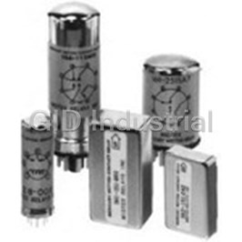
Catalog 1308242 Issued 3-03 P&B 159/160 series Mercury-Wetted Reed Relays Users should thoroughly review the technical data before selecting a product part number. It is recommended that users also seek out the pertinent approvals files of the agencies/laboratories and review them to ensure the product meets the requirements for a given application. General Information The mercury-wetted contact relay represents one of the more sophisticated types of relays made today. The early pioneer work in mercury-wetted contact switching dates back to the 1950’s, as telephone laboratory scientists sought out the “perfect contact”. Mercury- wetted contacts represent the nearest thing to the perfect contact yet developed, being characterized by such parameters as: bounce-free operation; very low and stable contact resistance; hermetic protection; fast operating speeds; Form C or Form D contact, action contact life measured in billions of operations. The only major weakness of a mercury- wetted contact relay is the necessity to mount the relay within 30° of a vertical position, due to its position sensitivity. While there are several variations of the mercury-wetted contact relay on the market, the basic contact element has essential concepts in common. The mercury-wetted contact element consists of a glass-encapsulated nickel-iron reed with its base immersed in a pool of mercury. The free reed cantilever projects upward between sets of stationary contact electrodes, which have been glass-sealed in proper juxtaposition at the top of the glass chamber. The mercury is induced to flow up the cantilever by capillary action, wetting mercury on both the cantilever contact tip as well as the stationary contacts. Thus a mercury-to-mercury contact is maintained on both the normally-closed and normally-open contacts, and the system is self-replenishing. The 2-ampere mercury-wetted capsule is shown far left. Along with the inherent fast actuation of the capsule and excellent load-handling capacity, the mercury-wetted contacts exhibit extremely long life, as the mercury films re-establish at each closure and contact erosion is eliminated. Contact interface resistance is very low and 2 Ampere stable, and as the mercury films are elastic, contact bounce is eliminated. A dynamic Capsule sequence of the mercury-wetted contact action is shown below. While the below sequence portrays a Form D (make-before-break) contact action, a true Form C (break-before-make) contact can be provided by proper control of the mercury film dynamics and the contact electrode spacing. The mercury-wetted contact capsules generally are mounted within a coil assembly, and with appropriately mounted bias magnets, mounting base and magnetic shielded enclosures. The more popular assemblies contain one or two capsules in a convenient printed circuit mounting module. Mercury-wetted relays can be adjusted to operate with very low levels of input power, in the order of 10-20 milliwatts. Thus, power gain switching of as great as 10,000 can be realized. For all but very light contact loads, contact protection is required to limit the current or voltage rise time across the contacts. Form D Mercury-Wetted Contact Action As Seen In High-Speed Sequence (1) Mercury (shown in black) covers armature and contact points; (2) and (3) as armature moves from open to closed position, mercury filament joins both contacts momentarily; (4) ruptured mercury surfaces accelerate away from each other, providing rapid breaking action; (5) as contact surfaces join, mercury wetting dampens rebound, eliminates electrical chatter, and provides contact reliability. SPDT (Form C or Form D) Contact Specifications Material Rating (Switched Load) (Carry Load) Bridging and Transfer Time Contact Resistance Life Expectancy Mercury-wetted 2 amperes 5 amperes When operated by a single 14 milliohms typical; 1 billion platinum contacts maximum maximum DC pulse, the bridging or 20 milliohms maximum operations hermetically 500 volts maximum Not switched transfer time will be greater Stable within minimum sealed in an 100 VA maximum than 50 microseconds, but ±2 milliohms at rated load inert atmosphere less than 500 microseconds. throughout life. Dimensions are shown for Dimensions are in inches over Specifications and availability www.tycoelectronics.com reference purposes only. (millimeters) unless otherwise subject to change. Technical support: 308 specified. Refer to inside back cover. Catalog 1308242 Issued 3-03 P&B Mercury-Wetted Relays Contact Protection The essentially infinite life of mercury-wetted contact relays may only be realized if the requirements for suitable contact protection are observed. In that the goal is control of the rate of rise of voltage across the contacts when the circuit is opened (rather than peak transient limiting), the only suitable protection recognized is an RC network. Values of R and C may be calculated using the formula shown, or may be obtained from the direct reading nomograph. Nomograph Explanation I=Steady state current at time of circuit opening E=Open circuit voltage Find I on the ordinate scale. Read C on the scale adjacent to I. R is found at the intersection of I and E. To reduce voltage transient amplitudes, C may be increased up to 10 times calculated values. (R must be calculated value.) For I=0.5 amps or less and E=50 volts or less R may be omitted C must be calculated value Resistor Tolerances ER Less than 70V R up to 2R 70V to 100V ±50% 100V to 150V ±10% Greater than 150V ±5% Specifications Parameter 159 Series 160 Series Coils Single Wound–max. ohms 8,600 9,000 Double Wound–max. ohms 4,275 4,500 Rating–Watts Continous 2.0 1.75 Temp. Rise–°C per watt 30° 35° Dielectric Breakdown–RMS, 60Hz 1,000 1,000 Insulation Resistance–Megohms–500 VDC 1,000 1,000 Capacitance–Armature to Coi pf, Typical 9.0 9.0 Electrostatic Shielding–Optional yes yes Typical Operate Times–mS, 2X Must Operate 1-3 1-3 Typical Release Times–mS, 2X 2.5 2.5 Contact Form Available Form C, D Form C, D Adjustments Available Single-side-stable yes yes Bi-stable yes yes Polar 1% Balance yes yes Temperature Range Operating °C All types – 38.8°C to + 85°C Storage °C All types – 65°C to + 100°C Weight–ounces 2.0 0.5 Encapsulant Polyurethane Polyurethane Mounting Method PCB PCB Dimensions are shown for Dimensions are in inches over Specifications and availability www.tycoelectronics.com reference purposes only. (millimeters) unless otherwise subject to change. Technical support: 309 specified. Refer to inside back cover. Catalog 1308242 Issued 3-03 P&B 159 series Mercury-Wetted Reed Relays Features Outline Dimensions 159 series relays are available in a Form C or Form D 2 amp contact arrangement, single or dual coil and printed circuit board terminals. Weight: 1.0 ounce Positive potential applied to the start of the winding indicated by the symbol will close the contacts shown open on the electrical schematics. For reset of bistable relays, reversed polarity must be applied. Wiring Diagrams Note: Relay must be mounted within 30° of vertical and suitable contact Single Coil Double Coil protection must be used. Part Numbering System Relay Series Enclosure And Terminals Contacts And Adjustment Coils Standard Or Special 160 1A-1Z–Single Coil 00–Standard 1–.625 Ht., .125 Lg. 1–1D Single-Side-Stable 2–.625 Ht., .156 Lg. 2K-2V–Double Coil A1-Z9–Special 2–1D Bistable 7A-7T–Single Coil Customer Requirement 3–.625 Ht., .187 Lg. 5–1C Single-Side-Stable 4–.625 Ht., .250 Lg. 8A-8Z–Bifilar Coil 6–1C Bistable 9A-9Z–Double Coil 7–1C Dynamic (1%) (Concentric) Balanced Bistable 1S and 2S–Special 0–Special 0–Special Example: 159-151N00 is a 159 series relay, enclosure height of .625 in., pin length of .125 in., Form C contact, single-side-stable adjustment, single coil 1N, of completely standard construction. Coil Characteristics and Part Numbers One Winding Single-Side-Stable 40 Milliwatts Part Number Coil Resistance Must Operate Must Operate Must Release Maximum Coils Voltage (VDC) Voltage (VDC) (Ohms) Current (MA-DC) Voltage (VDC) Form C Form D 1A 2.2 116 .28 .06 2.1 159-151A00 159-111A00 1B 3.9 86 .37 .07 2.8 159-151B00 159-111B00 1C 6.4 67 .47 .09 3.6 159-151C00 159-111C00 1D 9.0 60 .60 .12 4.3 159-151D00 159-111D00 1E 14 47 .72 .15 5.3 159-151E00 159-111E00 1F 24 35 .93 .19 6.9 159-151F00 159-111F00 1G 34 32 1.2 .24 8.2 159-151G00 159-111G00 1H 56 24 1.5 .30 11 159-151H00 159-111H00 1J 86 20 1.9 .39 13 159-151J00 159-111J00 1K 140 15 2.3 .46 17 159-151K00 159-111K00 1L 225 12 2.9 .59 21 159-151L00 159-111L00 1M 385 9.0 3.8 .73 28 159-151M00 159-111M00 1N 620 7.0 4.8 .95 35 159-151N00 159-111N00 1P 940 5.8 6.0 1.2 43 159-151P00 159-111P00 1Q 1,450 4.8 7.7 1.6 54 159-151Q00 159-111Q00 1R 2,430 3.6 9.7 2.0 70 159-151R00 159-111R00 1T 3,620 2.9 12 2.3 85 159-151T00 159-111T00 1U 5,500 2.5 15 3.0 105 159-151U00 159-111U00 1V 8,600 2.0 19 3.8 130 159-151V00 159-111V00 Dimensions are shown for Dimensions are in inches over Specifications and availability www.tycoelectronics.com reference purposes only. (millimeters) unless otherwise subject to change. Technical support: 310 specified. Refer to inside back cover. Catalog 1308242 Issued 3-03 P&B 159 Series (continued) – Coil Characteristics and Part Numbers Two Windings Single-Side-Stable 80 Milliwatts Per Winding Part Number Must Operate Must Operate Must Release Maximum Dielectric Stand Coil Resistance Coils Current (MA-DC) Voltage (VDC) Voltage (VDC) Voltage (VDC) Off Between (Ohms) (Either Winding) (Either Winding) (Either Winding) (Either Winding) Form C Form D Coils (VDC) 2K 70/70 30 2.3 .47 12 500 159-152K00 159-112K00 2L 159-152L00 115/115 23 3.0 .60 15 500 159-112L00 2M 190/190 18 3.8 .79 19 400 159-152M00 159-112M00 2N 159-152N00 325/325 14 5.0 1.0 26 400 159-112N00 2P 490/490 12 6.2 1.3 31 400 159-152P00 159-112P00 2Q 730/730 9.6 7.7 1.6 38 400 159-152Q00 159-112Q00 2R 159-152R00 1250/1250 7.2 10 2.0 50 400 159-112R00 2T 1860/1860 5.8 12 2.5 61 200 159-152T00 159-112T00 2U 159-152U00 2760/2760 5.0 15 3.0 74 200 159-112U00 2V 4275/4275 3.9 18 3.8 92 200 159-152V00 159-112V00 Two Windings Single-Side-Stable 40 Milliwatts Per Winding 159-162K00 2K 70/70 15 .30 1.2 12 500 159-122K00 159-162L00 115/115 12 .37 1.5 15 159-122L00 2L 500 159-162M00 2M 190/190 9.0 .47 1.9 19 400 159-122M00 159-162N00 325/325 7.0 .62 2.5 26 159-122N00 2N 400 159-162P00 2P 490/490 5.8 .77 3.1 31 400 159-122P00 159-162Q00 2Q 730/730 4.8 .97 3.9 38 400 159-122Q00 159-162R00 1250/1250 3.6 1.2 5.0 50 159-122R00 2R 400 159-162T00 2T 1860/1860 3.0 1.5 6.0 61 200 159-122T00 159-162U00 2760/2760 2.5 1.8 7.5 74 159-122U00 2U 200 159-162V00 2V 4275/4275 2.0 2.3 9.2 92 200 159-122V00 Two Windings Bifilar Windings Bistable 40 Milliwatts Per Winding 159-168A00 8A 135/135 16 .48 2.4 16.4 500 159-128A00 159-168B00 170/170 15.5 .58 2.9 18.5 159-128B00 8B 400 159-168C00 8C 200/200 13.3 .58 2.9 20.0 400 159-128C00 159-168D00 310/310 11.9 .82 4.1 24.9 159-128D00 8D 400 159-168E00 8E 460/460 7.8 .80 4.0 30.3 400 159-128E00 159-168F00 8F 675/675 6.5 .96 4.8 36.7 400 159-128F00 159-168G00 810/810 6.85 1.2 6.1 40.2 159-128G00 8G 400 159-168H00 8H 1000/1000 6.75 1.5 7.4 44.7 400 159-128H00 159-168J00 1240/1240 5.6 1.4 7.0 49.8 159-128J00 8J 400 159-168K00 8K 2300/2300 3.82 1.9 9.7 67.8 200 159-128K00 Note: All values at 25°C. Resistances specified are ±10%. Maximum voltages based on 2 watts continuous dissipation. One Winding Single-Side-Stable 115 Milliwatts And Bistable 25 Milliwatts Single-Side-Stable Bistable Nominal Must Operate Must Operate Must Maximum Part Number Must Operate Must Operate Must Part Number Resistance Current Voltage Release Voltage Release Current Voltage (Ohms) Voltage Voltage (MA-DC) (VDC) (VDC) (MA-DC) (VDC) Form C Form D Form C Form D (VDC) (VDC) 159-167A00 159-127A00 18 66.6 159-157A00 159-117A00 31.2 1.3 .18 6.0 .12 .62 37.4 159-157B00 159-117B00 17.8 159-167B00 159-127B00 65 2.7 .36 11.4 .26 1.3 159-167C00 159-127C00 85 33.3 159-157C00 159-117C00 15.6 3.1 .42 13.0 .30 1.5 37.7 159-157D00 159-117D00 17.6 159-167D00 159-127D00 90 3.8 .51 13.4 .36 1.8 159-167E00 159-127E00 115 30.0 159-157E00 159-117E00 14.0 3.8 .51 15.1 .36 1.8 159-167F00 159-127F00 275 17.0 159-157F00 159-117F00 8.0 5.2 .77 23.4 .50 2.5 12.9 159-157G00 159-117G00 6.0 159-167G00 159-127G00 450 6.4 .85 30.0 .60 3.0 159-167H00 159-127H00 675 11.6 159-157H00 159-117H00 5.4 8.6 1.1 36.7 .80 4.0 10.1 159-157J00 159-117J00 4.7 159-167J00 159-127J00 940 10.5 1.4 43.3 .98 4.9 159-167K00 159-127K00 950 12.1 159-157K00 159-117K00 5.7 12.7 1.7 43.6 1.2 6.0 159-167L00 159-127L00 1250 9.4 159-157L00 159-117L00 4.4 12.9 1.8 50.0 1.2 6.1 8.3 159-157M00 159-117M00 3.9 159-167M00 159-127M00 1425 13 1.8 53.4 1.2 6.2 159-167N00 159-127N00 1800 9.4 159-157N00 159-117N00 4.4 18.6 2.6 60.0 1.7 8.8 7.5 159-157P00 159-117P00 3.5 159-167P00 159-127P00 1950 17.6 2.1 62.4 1.5 7.5 159-167Q00 159-127Q00 2400 7.35 159-157Q00 159-117Q00 3.4 20.6 2.6 69.2 1.8 9.0 5.55 159-157R00 159-117R00 2.6 159-167R00 159-127R00 4000 24.4 3.3 89.5 2.3 159-167T00 159-127T00 4000 159-157T00 159-117T00 1.9 17.6 2.4 89.5 1.6 8.3 Dimensions are shown for Dimensions are in inches over Specifications and availability www.tycoelectronics.com reference purposes only. (millimeters) unless otherwise subject to change. Technical support: 311 specified. Refer to inside back cover. Catalog 1308242 Issued 3-03 P&B 160 series Mercury-Wetted Reed Relays Features Outline Dimensions 160 series relays are available in a single Form C or Form D two ampere contact arrangement, single or dual coil and printed circuit board terminals. The part numbers shown on the adjacent page are for relays with 0.093” terminal spacing. The part number designator for the 0.100” grid is a 160- 3XXXXX for a pin of 0.09” length, and 160-4XXXXX for a pin of 0.125” length. Positive potential applied to the start of the winding indicated by the symbol will close the contacts shown open on the electrical schematics. For reset of bistable relays, reversed polarity must be applied. Weight 0.5 ounces. UL File E55708 Note: Relay must be mounted within 30° of vertical and suitable contact protection must be used. Wiring Diagrams Grid 0.093 Grid 0.100 (160-1) (160-3) (160-2) (160-4) Single Coil Double Coil Part Numbering System Relay Series Enclosures And Terminals Contacts and Adjustments Standard or Special Coil 160 1–1D Single-Side-Stable 1–.090 Lg., .093 Grid 00–Standard 1A-1Z–Single Coil 2–1D Bistable A1-Z9–Special 2–.125 Lg., .093 Grid 2A-2Z–Double Coil 5–1C Single-Side-Stable 3–.090 Lg., .100 Grid Customer Requirement 6–1C Bistable 4–.125 Lg., .100 Grid 1S–Special Single Coil 7–1C Dynamic (1%) 2S–Special Double Coil Balanced Bistable 0–Special 0–Special Example: 160-151K00 is a 160 series relay, enclosure height of .400 in., pin length of .090 in., Form C contact, single-side-stable adjustment, single coil 1K, of completely standard construction. Coil Characteristics and Part Numbers Two Windings Bistable 20 Milliwatts Per Winding Part Number Must Operate Must Not Operate Must Operate Maximum Dielectric Standoff Coil Resistance Coil Voltage (VDC) Current (MA-DC) Voltage (VDC) Voltage (VDC) Between Coils (Ohms) Form C Form D (Either Winding) (Either Winding) (Either Winding) (One Winding Only) (VDC) 160-162K00 160-122K00 2K 60/60 17 .29 1.1 10 500 160-162L00 160-122L00 2L 90/90 15 .38 1.5 13 400 160-162M00 160-122M00 2M 155/155 11 .49 1.9 16 400 160-162N00 160-122N00 2N 205/205 10 .61 2.3 19 400 160-162P00 160-122P00 2P 340/340 7.5 .73 2.8 24 400 160-162Q00 160-122Q00 2Q 560/560 6.0 .98 3.6 31 400 160-162R00 160-122R00 2R 870/870 4.7 1.2 4.5 39 200 160-162T00 160-122T00 2T 1320/1320 3.8 1.4 5.5 48 200 160-162U00 160-122U00 2U 1980/1980 3.2 1.8 7.0 59 200 160-162V00 160-122V00 2V 3000/3000 2.7 2.3 9.0 73 200 160-162W00 160-122W00 2W 4500/4500 2.1 2.8 11.0 89 200 Note: All values at 25°C. Resistances specified are ±10%. Maximum voltages based on 1.75 watts continuous dissipation. Dimensions are shown for Dimensions are in inches over Specifications and availability www.tycoelectronics.com reference purposes only. (millimeters) unless otherwise subject to change. Technical support: 312 specified. Refer to inside back cover. Catalog 1308242 Issued 3-03 P&B 160 Series (continued) – Coil Characteristics and Part Numbers One Winding Single-Side-Stable 40 Milliwatts Part Number Maximum Coil Resistance Must Operate Must Operate Must Release (Ohms) Voltage (VDC) Current (MA-DC) Voltage (VDC) Voltage (VDC) Form C Form D 160-151A00 160-111A00 113 .27 .05 2.0 2.2 160-151B00 160-111B00 103 .35 3.1 .07 2.3 160-151C00 160-111C00 90 .43 .08 2.8 4.4 160-151D00 160-111D00 80 .52 5.9 .10 3.2 160-151E00 160-111E00 49 .71 .14 4.8 13.0 160-151F00 160-111F00 43 .87 18.7 .18 5.7 160-151G00 160-111G00 36 1.1 27.7 .22 7.0 160-151H00 160-111H00 25 1.4 .28 9.4 50 160-151J00 160-111J00 23 1.8 70 .35 11 160-151K00 160-111K00 16 2.3 .46 15 125 160-151L00 160-111L00 14 2.9 185 .60 18 160-151M00 160-111M00 11 3.8 .77 24 325 160-151N00 160-111N00 10 4.6 435 .94 28 160-151P00 160-111P00 7.5 5.7 680 1.1 35 160-151Q00 160-111Q00 5.9 7.2 1.4 44 1,120 160-151R00 160-111R00 4.6 8.8 1,750 1.7 55 160-151T00 160-111T00 3.8 11 2.2 68 2,650 160-151U00 160-111U00 3.2 14 3,900 2.7 83 160-151V00 160-111V00 2.6 17 3.5 103 6,100 160-151W00 160-111W00 2.1 21 9,000 4.2 125 Two Windings Single-Side-Stable 80 Milliwatts Per Winding Part Number Must Operate Must Not Operate Must Operate Maximum Dielectric Standoff Coil Resistance Current (MA-DC) Voltage (VDC) Voltage (VDC) Voltage (VDC) Between Coils (Ohms) (Either Winding) (Either Winding) (Either Winding) (One Winding Only) (VDC) Form C Form D 160-152K00 160-112K00 60/60 33 2.2 .44 10 500 160-152L00 160-112L00 90/90 29 2.9 .58 13 400 160-152M00 160-112M00 155/155 22 3.7 .74 16 400 160-152N00 160-112N00 205/205 20 4.5 .92 19 400 160-152P00 160-112P00 340/340 15 5.6 1.1 24 400 160-152Q00 160-112Q00 560/560 10.8 7.9 1.3 31 400 160-152R00 160-112R00 870/870 9.3 9.0 1.8 39 200 160-152T00 160-112T00 1,320/1,320 7.5 11.0 2.2 48 200 160-152U00 160-112U00 1,980/1,980 6.4 14.0 2.8 59 200 160-152V00 160-112V00 3,000/3,000 5.3 18.0 3.5 73 200 160-152W00 160-112W00 4,500/4,500 4.2 21.0 4.2 89 200 Dimensions are shown for Dimensions are in inches over Specifications and availability www.tycoelectronics.com reference purposes only. (millimeters) unless otherwise subject to change. Technical support: 313 specified. Refer to inside back cover.
Frequently asked questions
How does Electronics Finder differ from its competitors?

Is there a warranty for the 4-1608003-2?
Which carrier will Electronics Finder use to ship my parts?
Can I buy parts from Electronics Finder if I am outside the USA?
Which payment methods does Electronics Finder accept?
Why buy from GID?

Quality
We are industry veterans who take pride in our work

Protection
Avoid the dangers of risky trading in the gray market

Access
Our network of suppliers is ready and at your disposal

Savings
Maintain legacy systems to prevent costly downtime

Speed
Time is of the essence, and we are respectful of yours
Related Products
Reed Relay 15VDC 2KOhm 1A SPST-NO(19.3x5.7)mm THT Dry 1-1393763-0
Reed Relay 15VDC 2KOhm 0.5A SPST-NO(19.3x7.5x5.7)mm THT Dry 1-1393763-2
Reed Relay 15VDC 2KOhm 0.5A SPST-NO(19.3x5.7)mm THT Dry 1-1393763-3
Reed Relay 24VDC 2KOhm 0.5A SPST-NO(19.3x5.7)mm THT Dry 1-1393763-4
Reed Relays SPST-NO 1A 24VDC 2KOhm Thru-Hole 1-1393763-5
Reed Relays 24VDC 2KOhm 0.5A SPST-NO (19.3x5.7)mm THT Dry 1-1393763-6
Request a Quote

The quote request has been received
Close

Facing challenges or have inquiries? Feel free to contact us!
Call Us +1-469-283-2440
What they say about us
FANTASTIC RESOURCE
One of our top priorities is maintaining our business with precision, and we are constantly looking for affiliates that can help us achieve our goal. With the aid of GID Industrial, our obsolete product management has never been more efficient. They have been a great resource to our company, and have quickly become a go-to supplier on our list!
Bucher Emhart Glass
EXCELLENT SERVICE
With our strict fundamentals and high expectations, we were surprised when we came across GID Industrial and their competitive pricing. When we approached them with our issue, they were incredibly confident in being able to provide us with a seamless solution at the best price for us. GID Industrial quickly understood our needs and provided us with excellent service, as well as fully tested product to ensure what we received would be the right fit for our company.
Fuji
HARD TO FIND A BETTER PROVIDER
Our company provides services to aid in the manufacture of technological products, such as semiconductors and flat panel displays, and often searching for distributors of obsolete product we require can waste time and money. Finding GID Industrial proved to be a great asset to our company, with cost effective solutions and superior knowledge on all of their materials, it’d be hard to find a better provider of obsolete or hard to find products.
Applied Materials
CONSISTENTLY DELIVERS QUALITY SOLUTIONS
Over the years, the equipment used in our company becomes discontinued, but they’re still of great use to us and our customers. Once these products are no longer available through the manufacturer, finding a reliable, quick supplier is a necessity, and luckily for us, GID Industrial has provided the most trustworthy, quality solutions to our obsolete component needs.
Nidec Vamco
TERRIFIC RESOURCE
This company has been a terrific help to us (I work for Trican Well Service) in sourcing the Micron Ram Memory we needed for our Siemens computers. Great service! And great pricing! I know when the product is shipping and when it will arrive, all the way through the ordering process.
Trican Well Service
GO TO SOURCE
When I can't find an obsolete part, I first call GID and they'll come up with my parts every time. Great customer service and follow up as well. Scott emails me from time to time to touch base and see if we're having trouble finding something.....which is often with our 25 yr old equipment.
ConAgra Foods