

 Manufacturers
TE CONNECTIVITY 45730

Description
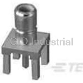
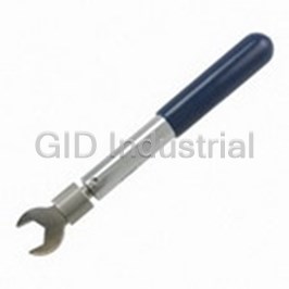
Single- Action Double- Action Hand Tool
45730
Part Number
45730
Price
Request Quote
Manufacturer
TE CONNECTIVITY
Lead Time
Request Quote
Category
Fasteners, Hardware and Fluid Transfer » Hardware Tools
Specifications
Manufacturer
TE Connectivity
Manufacturers Part #
45730
Industry Aliases
45730
Sub-Category
Hardware Tools
Brand
AMP
Factory Pack Quantity
1
Datasheet
DDEController?Action=showdoc&DocId=Specification+Or+Standard%7F408-1532%7FK%7Fpdf%7FEnglish%7FENG_SS_408-1532_K.pdf
145 KiB

Extracted Text
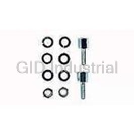
Instruction Sheet Single-ActionDouble-Action (SADA)HandTools45730, 408--1532 46467,46468,46469,and46470 04AUG 09 RevK PROPERUSEGUIDELINES CumulativeTraumaDisorderscanresultfromtheprolongeduseofmanuallypoweredhandtools.Handtoolsareintendedforoccasionaluseandlowvolume applications.Awide selection ofpowered application equipmentforextended--use,production operationsisavailable. Tool Part Number Color Code Head Assembly Indenter (Moving) Die CERTI--CRIMP* Hand Crimping Tool Ratchet Control Crimping Chambers Anvil (Stationary) Die Locator TOOL WIRE STRATO--THERM*TERMINALORSPLICEG PARTNUMBER COLORCODE SIZE(AWG) INSULDIA(mm[in.]) PARTNUMBER COLORCODE 45730 Yellow 26--24 1.02--1.27[.040--.050] 324370 Yellow 22 1.02--1.27[.040--.050] 133327 22--20 151475 46467 46467 W Wh hiite te A Alluminum uminum 1 1.17 17--1.60 160[[.046 046--.063 063]] 22--20 329645 22--20 1.73[.068] Max 132082 4 46468 6468 R Re ed d R Re ed d 18--16 1.63--2.23[.064--.088] 329647 46469 Blue 14 2.03--3.81[.080--.150] 322694322695 White 133329323060 46470 Yellow 12--10 1.78--3.05[.070--.120] Yellow 323061323062 G The product part numbers listed are not intended to be a complete list. Refer to Catalog 82011 or contact Product Information at the number listed at the bottom of this page. Figure1 1. INTRODUCTION Reasons for reissue of this instruction sheet are provided in Section 7, REVISION SUMMARY. SADA Hand Tools 45730, 46467, 46468 (shown in Figure 1), 46469, and 46470 crimp STRATO--THERM Terminals and Splices listed in Figure 1 onto stranded 2. DESCRIPTION or solid wire. Each tool features a head assembly with a stationary All dimensions on this document are in metric (anvil) die, moving (indenter) die, and locator. When NOTE units [with U.S. customary units in brackets]. closed, the dies form two crimping chambers. The Figures and illustrations are for identification only dies apply the “W” crimp to the wire barrel and “O” i and are not drawn to scale. crimp to the insulation barrel of the terminal or splice. E2009 Tyco Electronics Corporation, Harrisburg, PA TOOLING ASSISTANCE CENTER1--800--722--1111 This controlled document is subject to change. 1 of 5 PRODUCT INFORMATION1--800--522--6752 Forlatest revision and Regional CustomerService, All International Rights Reserved visit ourwebsite atwww.tycoelectronics.com TE logo and Tyco Electronics are trademarks. LOCB *Trademark. Otherproducts, logos, and company names used are the property of theirrespective owners. 408-1532 SADAHandTools45730,46467,46468,46469,and46470 The locator assists in positioning the terminal or 2. Position the terminal or splice onto the anvil die splice between the dies. The CERTI--CRIMP hand so that the end of the wire barrel rests against the crimping tool ratchet control ensures full crimping of locator. SeeFigure3. the product. Once engaged, the ratchet will not 3. Squeeze the tool handles just enough to firmly release until the handles have been FULLY closed. hold the wire barrel in place. Take care not to The back of each tool is marked with the part number deform the wire barrel. and color code. 4. Insert the stripped end of the wire into the wire CAUTION The dies bottom before the ratchet releases. This barrel until the wire bottoms. Refer to Figure 3. feature ensures maximum electrical and tensile performance of the crimp. Do NOT re--adjust the 5. Holding the wire in place, squeeze the tool ! ratchet. handles until the ratchet releases. Allow the handles to open FULLY. 3. PREPARATION Note: Splice Shown (Applies to Terminal Also) 1. For splices, slide the insulation bushings onto the end of each wire. Slide the sleeve (or insulation tubing) onto one of the wires. Refer to Figure 2. Stripped Wire 2. Strip the wires according to the dimensions shown in Figure 2. Do NOT nick or cut the wire strands. B (Length ofWire Barrel)+ 0.79 [.031]= Strip Length Endof WireBarrel Against Tool Locator Splice Sleeve Color--Coded Ring (2 Places, Ref) Anvil Die Bushing Stripped Locator Wire “B” Strip Length Figure3 Bushing 6. For splices, re--position the splice onto the anvil Strip Length die so that the end of the uncrimped wire barrel Note: Not to Scale rests against the locator, and repeat Steps 3 through 5. Terminal 7. Remove the terminal or splice from the tool, and inspect the crimp according to Figure 4. “B” Strip Length Note: Splice Shown (Applies to Terminal Also) Wire Insulation is Not Cut or Broken Crimp is Symmetrical Figure2 on Both Sides of Wire Barrel 4. CRIMPINGPROCEDURE Wire Conductor Extends Beyond These tools are coated with a preservative to NOTE Endof WireBarrel prevent rust or corrosion. Wipe the preservative from the tool, particularly from the dies, before Crimp May Be Off Center, But i using the tool. Not Off End, of Wire Barrel 1. Open the tool dies by squeezing the tool Figure4 handles together until the ratchet releases. 2 of 5 Tyco ElectronicsCorporation RevK 408-1532 SADAHandTools45730,46467,46468,46469,and46470 For splices, continue with the following: 5. MAINTENANCEANDINSPECTION It is recommended that a maintenance and inspection 8. Slide the bushings against the wire barrels, then program be performed periodically to ensure center the sleeve over the splice. Make sure that dependable and uniform terminations. Frequency of the bushings and sleeve are properly positioned inspection depends on: according to the dimensions shown in Figure 5. Sleeve Extends Slightly from 0.79 mm [.031 in.] (Approx) Ring and Crimped Bushing Bushing Extends from Sleeve Extends Slightly from Sleeve Sleeve is Centered Sleeve is Centered Over Splice Over Crimped Splice Figure7 Figure5 1. The care, amount of use, and handling of the hand tool. 9. Position the splice onto the anvil die so that the color--coded ring on the sleeve is centered in the 2. The presence of abnormal amounts of dust and die and the end of the sleeve rests against the dirt. locator. SeeFigure6. 3. The degree of operator skill. 4. Your own established standards. The tool is inspected before being shipped; however, it is recommended that the tool be inspected immediately upon arrival at your facility to ensure that the tool has not been damaged during shipment. Due to the precision design, it is important that CAUTION no parts of these tools be interchanged. ! End of Sleeve Against Locator 5.1. DailyMaintenance 1. Remove dust, moisture, and other contaminants Ring Centered with a clean brush, or a soft, lint--free cloth. Do on Anvil Die NOT use objects that could damage the tool. 2. Make certain that the retaining pins are in place and that they are secured with retaining rings. Figure6 3. When not in use, keep the tool handles closed to prevent objects from becoming lodged in the 10. Squeeze the tool handles just enough to firmly dies. Store the tool in a clean, dry area. hold the color--coded ring in place. Take care not to deform the ring. If necessary, move the wire back 5.2. Lubrication and forth until the splice is centered in the sleeve. Lubricate all pins, pivot points, and bearing surfaces 11. Squeeze the tool handles until the ratchet with SAE 20 motor oil as follows: releases. Allow the handles to open FULLY, and Tool used daily—lubricate daily remove the splice from the tool. Tool used occasional)—lubricate weekly Tool used weekly—lubricate monthly 12. Re--position the splice onto the anvil die so that the uncrimped color--coded ring on the sleeve is Do NOT oil excessively. Wipe excess oil from tool, centered in the die and the end of the sleeve rests particularly from crimping area. Oil transferred from against the locator. the crimping area onto certain terminations may affect the electrical characteristics of an application. 13. Squeeze the tool handles until the ratchet releases. Allow the handles to open FULLY. 5.3. PeriodicInspection 14. Remove the splice from the tool, and inspect 1. The tool should be immersed (handles partially thecrimp accordingtoFigure7. closed) in a reliable commercial degreasing RevK Tyco ElectronicsCorporation 3 of 5 408-1532 SADAHandTools45730,46467,46468,46469,and46470 compound to remove accumulated dirt, grease, 2. Position the terminal or splice in the tool according to Section 3. and foreign matter. 2. Close tool handles until ratchet releases and SuggestedPlugGageDesignfor then allow them to open freely. If handles do not WireBarrel CrimpingChamber open quickly and fully, the spring is defective and A D must be replaced. See Section 6, REPLACEMENT AND REPAIR. 3. Inspect head assembly for worn, cracked, or broken areas. If damage is evident, return the tool for evaluation and repair. See Section 6, L REPLACEMENT AND REPAIR. GAGEELEMENT 5.4. GagingtheCrimpingChamber “D” “L” “A”DIMENSION TOOL ((D Diiaamet meter er)) ((L Leengt ngth h)) This inspection requires the use of a plug gage GO NO--GO +0.00[.000] (Min) conforming to the dimensions provided in Figure 8. To 0.660--0.668 0.810--0.813 1.58 gage the crimping chamber, proceed as follows: 45730 [.0260--.0263] [.0319--.0320] [.062] 1. Remove traces of oil or dirt from the crimping 0.940--0.947 1.090--1.092 2.34 chamber and plug gage. 46467 [.0370--.0373] [.0429--.0430] [.093] 2. Close the tool handles until it is evident that the 1.295--1.303 1.445--1.448 3.14 12.7 46468 dies have bottomed; then hold in position. Do NOT [.0510--.0513] [.0569--.0570] [.125] [.50] [ 50] force the dies beyond initial contact. 1.511--1.519 1.661--1.664 3.96 46469 [.0595--.0598] [.0654--.0655] [.156] 3. Align the GO element with the wire barrel crimping chamber. Push the element straight into 1.930--1.938 2.080--2.083 3.96 46470 the crimping chamber without using force. The GO [.0760--.0763] [.0819--.0820] [.156] element must pass completely through the SuggestedPlugGageDesignfor crimping chamber. InsulationBarrel CrimpingChamber 4. Align the NO--GO element, and try to insert it A straight into the same crimping chamber. The R NO--GO element may start entry, but must not pass completely through the crimping chamber. 5. Follow the same procedure for the insulation barrel crimping chamber using proper plug gage. W If crimping chambers conform to the gage inspection, GAGEELEMENT the tool is considered dimensionally correct, and should be lubricated with a THIN coat of any good “W” “A”DIMENSION TOOL SAE 20 motor oil. If not, the tool must be returned for ((W Wiid dtth h)) GO NO--GO further evaluation and repair. Refer to Section 6, +0.00[.000] REPLACEMENT AND REPAIR. 2.972--2.979 3.096--3.099 45730 2.77[.109] [.1170--.1173] [.1219--.1220] For additional information regarding the use of a plug 3.277--3.284 3.401--3.404 gage, refer to Instruction Sheet 408--7424. 46467 2.77[.109] [.1290--.1293] [.1339--.1340] 5.5. CERTI-CRIMPHandCrimpingToolRatchetControl 4.394--4.402 4.519--4.521 46468 3.18[.125] Inspection [.1730--.1733] [.1779--.1780] 4.978--4.986 5.103--5.105 The ratchet on these tools should be inspected to 46469 3.96[.156] [.1960--.1963] [.2009--.2010] ensure that the ratchet does not release prematurely, allowing the dies to open before they have fully 6.426--6.434 6.551--6.553 46470 5.54[.218] bottomed. Obtain a 0.025 mm [.001 in.] shim that is [.2530--.2533] [.2579--.2580] suitable for checking the clearance between the Figure8 bottoming surfaces of the dies. 3. Holding the wire in place, squeeze the tool Proceed as follows: handles until the ratchet releases. Hold the handles 1. Select the maximum size wire for the tool, and in this position, maintaining just enough tension to stripthe wireaccordingtoFigure2. keep the dies closed. 4 of 5 Tyco ElectronicsCorporation RevK 408-1532 SADAHandTools45730,46467,46468,46469,and46470 4. Check the clearance between the bottoming 1--800--526--5142, or send a facsimile of your surfaces of the dies. If the clearance is 0.025 mm purchase order to 717--986--7605, or write to: [.001 in.] or less, the ratchet is satisfactory. If CUSTOMER SERVICE (038--035) clearance exceeds 0.025 mm [.001 in.], the ratchet TYCO ELECTRONICS CORPORATION is out of adjustment and must be repaired. See PO BOX 3608 Section 6, REPLACEMENT AND REPAIR. HARRISBURG PA 17105--3608 6. REPLACEMENTANDREPAIR For customer repair service, contact a representative at 1--800--526--5136. Customer--replaceable parts are listed in Figure 9. A complete inventory should be stocked and controlled to prevent lost time when replacement of 7. REVISIONSUMMARY parts is necessary. Parts other than those listed S Updated document to corporate requirements should be replaced by Tyco Electronics to ensure quality and reliability. Order replacement parts S Added new information for hand tool 46467 in through your Tyco Electronics Representative, or call table in Figure 1 1 2 3 57.2 [2.25] (Closed) 4 5 22.22 [.875] 279.4 [11.00] REPLACEMENTPARTS PARTNUMBERFORTOOL Q QT TY YPER PER IITE TEM M D DE ES SC CRI RIP PT TIIO ON N TOOL 45730 46467 46468 46469 46470 1 8--59558--2 1--23619--6 8--59558--2 8--59558--2 300388 PIN, Retaining 2 2 -- 21045--3 RING, Retaining 8j 3 39364 SPRING 1 4 2--23620--9 PIN, Retaining 1 5 -- 21045--6 RING, Retaining 8 j Tool 46470 requires 12 of these retaining rings. Figure9 RevK Tyco ElectronicsCorporation 5 of 5
Frequently asked questions
How does Electronics Finder differ from its competitors?

Is there a warranty for the 45730?
Which carrier will Electronics Finder use to ship my parts?
Can I buy parts from Electronics Finder if I am outside the USA?
Which payment methods does Electronics Finder accept?
Why buy from GID?

Quality
We are industry veterans who take pride in our work

Protection
Avoid the dangers of risky trading in the gray market

Access
Our network of suppliers is ready and at your disposal

Savings
Maintain legacy systems to prevent costly downtime

Speed
Time is of the essence, and we are respectful of yours
Related Products
Crimpers TOOL 1055236-1
Mini Torque Wrenches 1055258-1

Wrenches 2098 0351 54 1055276-1
Hand Tools CABLE BENDER 1055479-1
Connector Accessories Crimp Assembly Kit 1055779-1
Crimpers TOOL 1055835-1
Request a Quote

The quote request has been received
Close

Facing challenges or have inquiries? Feel free to contact us!
Call Us +1-469-283-2440
What they say about us
FANTASTIC RESOURCE
One of our top priorities is maintaining our business with precision, and we are constantly looking for affiliates that can help us achieve our goal. With the aid of GID Industrial, our obsolete product management has never been more efficient. They have been a great resource to our company, and have quickly become a go-to supplier on our list!
Bucher Emhart Glass
EXCELLENT SERVICE
With our strict fundamentals and high expectations, we were surprised when we came across GID Industrial and their competitive pricing. When we approached them with our issue, they were incredibly confident in being able to provide us with a seamless solution at the best price for us. GID Industrial quickly understood our needs and provided us with excellent service, as well as fully tested product to ensure what we received would be the right fit for our company.
Fuji
HARD TO FIND A BETTER PROVIDER
Our company provides services to aid in the manufacture of technological products, such as semiconductors and flat panel displays, and often searching for distributors of obsolete product we require can waste time and money. Finding GID Industrial proved to be a great asset to our company, with cost effective solutions and superior knowledge on all of their materials, it’d be hard to find a better provider of obsolete or hard to find products.
Applied Materials
CONSISTENTLY DELIVERS QUALITY SOLUTIONS
Over the years, the equipment used in our company becomes discontinued, but they’re still of great use to us and our customers. Once these products are no longer available through the manufacturer, finding a reliable, quick supplier is a necessity, and luckily for us, GID Industrial has provided the most trustworthy, quality solutions to our obsolete component needs.
Nidec Vamco
TERRIFIC RESOURCE
This company has been a terrific help to us (I work for Trican Well Service) in sourcing the Micron Ram Memory we needed for our Siemens computers. Great service! And great pricing! I know when the product is shipping and when it will arrive, all the way through the ordering process.
Trican Well Service
GO TO SOURCE
When I can't find an obsolete part, I first call GID and they'll come up with my parts every time. Great customer service and follow up as well. Scott emails me from time to time to touch base and see if we're having trouble finding something.....which is often with our 25 yr old equipment.
ConAgra Foods