

 Manufacturers
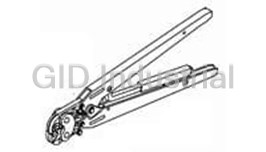
TE CONNECTIVITY 58174-1

Description
Specialty Hand Tools Easier On The Hand And Precise On The Crimp
58174-1
Part Number
58174-1
Price
Request Quote
Manufacturer
TE CONNECTIVITY
Lead Time
Request Quote
Category
Tools and Supplies » Assembly Tools
Specifications
Manufacturer
TE Connectivity
Manufacturers Part #
58174-1
Industry Aliases
58174-1
Sub-Category
Electronics Assembly Tools
Brand
AMP
Factory Pack Quantity
1
Datasheet
DDEController?Action=showdoc&DocId=Specification+Or+Standard%7F408-6877%7FB%7Fpdf%7FEnglish%7FENG_SS_408-6877_B.pdf
294 KiB

Extracted Text
Instruction Sheet Crimping Die Assemblies 408-6877 58085-1, 58086-1, and 58174-1 07 NOV 14 Rev C PROPER USE GUIDELINES Cumulative Trauma Disorders can result from the prolonged use of manually powered hand tools. Hand tools are intended for occasional use and low volume applications. A wide selection of powered application equipment for extended-use, production operations is available. Die Retaining Stationary Jaw Screws Indenter Die PRO-CRIMPER* III Crimping Die Frame Assembly Assembly 354940-1 (Ref) 58085-1 (Ref) Movable Anvil Die Jaw Center Contact Ferrule Crimping Crimping Chamber Chamber DIE ASSEMBLY CONNECTOR BASE PART NO. PART NO. 58085-1 221185, 221199, 221221, 221402 58086-1, 58174-1 221185, 221199, 221221 Figure 1 1. INTRODUCTION This instruction sheet covers the use and maintenance of Crimping Die Assemblies 58085-1, 58086-1, and 58174-1, which are used to crimp 75-Ohm RF Series BNC Dual Crimp Connectors. The die assemblies are designed to be used in PRO-CRIMPER III Frame Assembly 354940-1. Refer to Figure 1 for a list of connectors that are compatible with the die assemblies. For additional connector part number information, refer to the PRODUCT INFORMATION number listed at the bottom of this page. For instructions concerning the operation of the tool frame, refer to Instruction Sheet 408-9930. Read these instructions thoroughly before using the die assemblies. NOTE All dimensions are in millimeters [with inch equivalents in brackets]. Figures and illustrations are for identification only, and are not drawn to scale. Reasons for reissue are provided in Section 8, REVISION SUMMARY. 2. DESCRIPTION (Figure 1) Each die assembly consists of an indenter and an anvil, both of which contain two crimping chambers. The small crimping chamber produces a box crimp on the center contact of the connector, and the other crimping chamber crimps the connector ferrule. Each die is held in the tool frame by a single screw. 3. DIE INSTALLATION 1. Slide the die assembly into the partially-opened tool jaws. The anvil die must be installed in the movable jaw of the tool and the indenter in the stationary jaw. The center contact crimping chamber must be toward the front of the tool as shown in Figure 1. 2. Insert, but do not completely tighten, the die retaining screws. © 2014 TE Connectivity family of companies TOOLING ASSISTANCE CENTER 1-800-722-1111 This controlled document is subject to change. 1 of 5 All Rights Reserved PRODUCT INFORMATION 1-800-522-6752 For latest revision and Regional Customer Service, *Trademark visit our website at www.te.com. TE Connectivity, TE connectivity (logo), and TE (logo) are trademarks. Other logos, product, and/or company names may be trademarks of their respective owners. ORIGINAL INSTRUCTIONS 408-6877 3. Close the tool jaws and carefully align the dies so that the anvil die enters the indenter die. Once the anvil has entered the indenter, place a copper bus bar (1.57 ±0.05 mm [.062 ±.002in.] diameter) into the center contact crimping chamber of the die assembly. 4. With bus bar in place, close the tool jaws completely. Hold the tool handles together and tighten the die retaining screws with the appropriate screwdriver. 4. CRIMPING PROCEDURE NOTE For detailed information on cable selection, cable strip lengths, and proper assembly of the connector, refer to the instructions provided with the connector. Make sure the connector being used is compatible with the die assembly; then proceed as follows: 4.1. Center Contact (Figure 2) 1. Slide the ferrule onto the cable, then strip the cable to the proper dimensions. 2. Slide center contact onto center conductor of cable; then insert contact assembly into the center contact crimping chamber of the anvil die. See Figure 2. NOTE Make sure that the flange on the end of the center contact butts against the edge of the die. See Figure 2. 3. Crimp the center contact by holding the cable and contact in place and closing the tool handles until the ratchet releases. 4. Allow the handles to open fully, and remove the crimped center contact assembly from the crimping dies. Crimping the Center Contact Cross-Sectional View Flange on End Plug Contact of Contact Crimping Die Flange on End of Center Contact Butts Against Die Jack Contact Flange of End of Contact Anvil Die Stripped Cable Crimping Die Figure 2 4.2. Ferrule (Figure 3) 1. Insert the crimped center contact into the connector body until the cable dielectric butts against the dielectric inside the connector body. The flared cable braid must fit around the support sleeve of the connector body. 2. Slide the ferrule forward over the braid until the ferrule butts against the shoulder on the connector body. 3. Place the ferrule in the ferrule crimping chamber of the anvil die so that the shoulder on the connector body butts against the edge of the die. See Figure 3. 2 of 5 Rev C 408-6877 Crimping the Ferrule Shoulder on Connector Body Butts Against Edge of Die Ferrule in Crimping Chamber on Anvil Die Figure 3 4. Holding the assembly in place, close the tool handles until the ratchet releases. 5. Allow the handles to open fully, and remove the crimped assembly from the crimping dies. 5. CRIMP HEIGHT ADJUSTMENT (Figure 4) The tool frame assembly ratchet mechanism features an adjustment wheel with numbered settings. If the crimp height is not acceptable, adjust the ratchet as follows: 1. Remove the lockscrew from the ratchet adjustment wheel. 2. With a screwdriver, adjust the ratchet wheel from the opposite side of the tool. 3. Observe the ratchet adjustment wheel. If a tighter crimp is required, rotate the adjustment wheel COUNTERCLOCKWISE to a higher-numbered setting. If a looser crimp is required, rotate the adjustment wheel CLOCKWISE to a lower-numbered setting. 4. Replace the lockscrew. 5. Make a sample crimp and measure the crimp height. If the crimp height is acceptable, secure the lockscrew. If the dimension is unacceptable, remove lockscrew and continue to adjust the ratchet, and again measure a sample crimp. Screwdriver Ratchet Adjustment Wheel Lockscrew (Typ) Figure 4 3 of 5 Rev C 408-6877 6. MAINTENANCE AND INSPECTION 6.1. Daily Maintenance 1. Remove dust, moisture, and other contaminants with a clean brush or a soft, lint-free cloth. Do NOT use objects that could damage the dies. 2. Make sure the proper die retaining screws are in place and secured. 3. When the dies are not in use, mate and store them in a clean, dry area. 4. Store the tool with the tool handles closed to prevent objects from becoming lodged within the jaws. 6.2. Periodic Inspection Regular inspections should be performed by quality control personnel. A record of scheduled inspections should remain with the dies and/or be supplied to supervisory personnel responsible for the dies. The inspection frequency should be based on the amount of use, working conditions, operator training and skill, and established company standards. These inspections should be performed in the following sequence: Visual Inspection 1. Remove all lubrication and accumulated film by immersing the dies in a suitable commercial degreaser that will not affect paint or plastic material. 2. Make certain all die retaining screws, retaining rings, and die components are in place. If replacements are necessary, refer to Section 7, REPLACEMENT. 3. Check all bearing surfaces for wear. Remove and replace worn components. Center Contact Crimp Height Inspection Crimp height inspection is performed through the use of a micrometer with a modified anvil, commonly referred to as a crimp height comparator. TE does not market crimp height comparators. Refer to Instruction Sheet 408-7424 for detailed information on obtaining and using a crimp height comparator. Proceed as follows to check the crimp height of the center contact: 1. Select a center contact for the connector being used. 2. Refer to Section 4, CRIMPING PROCEDURE, and crimp the center contact accordingly. 3. Using a crimp height comparator, measure the crimp height as shown in Figure 5. If the crimp height conforms to that shown, the die assembly is considered dimensionally correct. If not, the dies must be replaced before returning them to service (refer to Section 7, REPLACEMENT). Gaging the Ferrule Crimping Chamber This inspection requires the use of a plug gage conforming to the diameters in Figure 5. TE does not manufacture or market these gages. To gage the ferrule crimping chamber, proceed as follows: 1. Close the jaws until the dies have bottomed, then HOLD the tool handles in this position. Do NOT force the dies beyond initial contact. 2. Align the GO element with the proper crimping chamber. Push the element straight into the crimping chamber without using force. The GO element must pass completely through the crimping chamber. 3. Align the NO-GO element and try to insert it straight into the same crimping chamber. The NO-GO element may start entry, but must not pass completely through. If the crimping chamber conforms to the gage inspection, the dies are considered dimensionally correct, and should be lubricated with a THIN coat of any good SAE 20 motor oil. If not, the dies must be replaced (refer to Section 7, REPLACEMENT). For additional information regarding the use of a plug gage, refer to Instruction Sheet 408-7424. 4 of 5 Rev C 408-6877 Measuring Center Contact Crimp Suggested Plug Gage for Ferrule Crimping Chamber 1.041-1.194 GO Dia NO-GO Dia Position Point [.041-.047] on Center of Wire Barrel Modified Crimping Chamber Anvil GAGE ELEMENT DIAMETER DIE ASSEMBLY PART NO. GO NO-GO 5.9690-5.9766 6.2205-6.2230 GO Element NO-GO Element 58085-1 [.2350-.2353] [.2449-.2450] “GO” gage must pass “NO-GO” gage may enter partially, 6.6040-6.802 6.8555-6.8580 58086-1 completely through but must not pass completely [.2600-.2603] [.2699-.2700] the die closure. through the die closure 4.1910-4.1986 4.4425-4.4450 58174-1 [.1650-.1653] [.1749-.1750] Figure 5 7. REPLACEMENT Parts listed in Figure 6 are customer-replaceable. A complete inventory can be stocked and controlled to prevent lost time when replacement of parts is necessary. Order replacements through your local TE Representative, or call 1-800-526-5142, or send a facsimile of your purchase order to 1-717-986-7605, or write to: CUSTOMER SERVICE (038-035) TYCO ELECTRONICS CORPORATION PO BOX 3608 HARRISBURG PA 17105-3608 8. REVISION SUMMARY Updated document to corporate requirements New logo 1 32.82 [1.292] B A 2 30.48 [1.20] WEIGHT: 85 g [3 oz] 11.89 [.468] DIE OPENING DIMENSIONS CUSTOMER-REPLACEABLE PARTS DIE ASSEMBLY CENTER CONTACT FERRULE INDENTER ANVIL QTY PER PART NO. “A” ±0.05 [±.002] “B” ±0.10 [±.004] (Item 1) (Item 2) ASSEMBLY 58085-1 1.12 [.044] 6.10 [.240] 313134-1 313135-1 1 58086-1 1.12 [.044] 6.73 [.265] 313134-2 313135-2 1 58174-1 1.12 [.044] 4.32 [.170] 313134-3 313135-3 1 Figure 6 5 of 5 Rev C
Frequently asked questions
How does Electronics Finder differ from its competitors?

Is there a warranty for the 58174-1?
Which carrier will Electronics Finder use to ship my parts?
Can I buy parts from Electronics Finder if I am outside the USA?
Which payment methods does Electronics Finder accept?
Why buy from GID?

Quality
We are industry veterans who take pride in our work

Protection
Avoid the dangers of risky trading in the gray market

Access
Our network of suppliers is ready and at your disposal

Savings
Maintain legacy systems to prevent costly downtime

Speed
Time is of the essence, and we are respectful of yours
Related Products

Torque Wrenches Are Used To Properly Install Or Disassemble The Connectors 1055419-1
Tool For RF Connectors 1055442-1
Tool For RF Connectors 1055443-1
Insertion Tool For RF Connectors 1055447-1
Insertion Tool For RF Connectors 1055448-1
Assembly Tools, Sma Right Angle Cable Plugs 1055451-1
Request a Quote

The quote request has been received
Close

Facing challenges or have inquiries? Feel free to contact us!
Call Us +1-469-283-2440
What they say about us
FANTASTIC RESOURCE
One of our top priorities is maintaining our business with precision, and we are constantly looking for affiliates that can help us achieve our goal. With the aid of GID Industrial, our obsolete product management has never been more efficient. They have been a great resource to our company, and have quickly become a go-to supplier on our list!
Bucher Emhart Glass
EXCELLENT SERVICE
With our strict fundamentals and high expectations, we were surprised when we came across GID Industrial and their competitive pricing. When we approached them with our issue, they were incredibly confident in being able to provide us with a seamless solution at the best price for us. GID Industrial quickly understood our needs and provided us with excellent service, as well as fully tested product to ensure what we received would be the right fit for our company.
Fuji
HARD TO FIND A BETTER PROVIDER
Our company provides services to aid in the manufacture of technological products, such as semiconductors and flat panel displays, and often searching for distributors of obsolete product we require can waste time and money. Finding GID Industrial proved to be a great asset to our company, with cost effective solutions and superior knowledge on all of their materials, it’d be hard to find a better provider of obsolete or hard to find products.
Applied Materials
CONSISTENTLY DELIVERS QUALITY SOLUTIONS
Over the years, the equipment used in our company becomes discontinued, but they’re still of great use to us and our customers. Once these products are no longer available through the manufacturer, finding a reliable, quick supplier is a necessity, and luckily for us, GID Industrial has provided the most trustworthy, quality solutions to our obsolete component needs.
Nidec Vamco
TERRIFIC RESOURCE
This company has been a terrific help to us (I work for Trican Well Service) in sourcing the Micron Ram Memory we needed for our Siemens computers. Great service! And great pricing! I know when the product is shipping and when it will arrive, all the way through the ordering process.
Trican Well Service
GO TO SOURCE
When I can't find an obsolete part, I first call GID and they'll come up with my parts every time. Great customer service and follow up as well. Scott emails me from time to time to touch base and see if we're having trouble finding something.....which is often with our 25 yr old equipment.
ConAgra Foods