

 Manufacturers
TE CONNECTIVITY 58195-1

Description
SDL Die Assy Round 4 Pos
58195-1
Part Number
58195-1
Price
Request Quote
Manufacturer
TE CONNECTIVITY
Lead Time
Request Quote
Category
Fasteners, Hardware and Fluid Transfer » Hardware Tools
Specifications
Manufacturer
TE Connectivity
Manufacturers Part #
58195-1
Industry Aliases
58195-1
Sub-Category
Hardware Tools
Brand
AMP
Factory Pack Quantity
1
Datasheet
DDEController?Action=showdoc&DocId=Specification+Or+Standard%7F408-9072%7FA%7Fpdf%7FEnglish%7FENG_SS_408-9072_A.pdf
127 KiB

Extracted Text
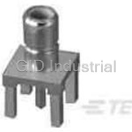
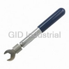
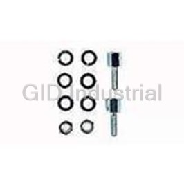
InstructionSheet 408--9072 SDLPLugsandReceptacles 11Mar 11 RevC Round-Cable Plug (Typ) Side-Entry Receptacle (Typ) PC Board or Panel Top-Entry Receptacle (Typ) PC Board or Flat-Cable Plug (Typ) Panel Figure 1 1. INTRODUCTION polarization (to prevent the insertion of a plug upside--down in a receptacle), primary strain relief This instruction sheet provides selection data and applied to the cable foil (shield), drain wires (providing covers the assembly of SDL plugs and receptacles. strain relief on the cable jacket), secondary strain Refer to Figure 1. Read these instructions and all relief for the main cable conductors, and preloaded referenced material carefully before starting assembly 1.27 [.050] centerline contacts which are terminated of the plugs or receptacles. to the conductors using the technique of insulation displacement. Internal or external key slots are Dimensions in this instruction sheet are in NOTE letter--coded to ensure that plugs are correctly millimeters [with inches in brackets]. Figures are matched to the receptacles. for reference only and are not drawn to scale. i In flat--cable plugs, the housing, which is already Reasons for reissue of this instruction sheet are shielded, is terminated to the flat cable using specific provided in Section 5, REVISION SUMMARY. tooling. In round--cable plugs, the housing subassembly is 2. DESCRIPTION (Figure1) first terminated to the round cable using specific The plug is available in 4, 6, 8, and 16 positions for tooling for housing termination. Top and bottom flat or round shielded 7--stranded cable and accept a shielding shells are latched around the housing and a wire size range of 28 to 24 AWG. The receptacle is strain relief ferrule is then crimped to the cable outlets available in 4, 6, 8, and 16 positions in either top-- or of the shells and the cable using specific tooling. side--entry configuration with or without a ground. In addition to shielding, the housing of either flat-- or The receptacle features a shielded housing and round--cable plugs features locking latches, positive printed circuit (pc) board tails. E2011 Tyco Electronics Corporation, a TE Connectivity Ltd. Company TOOLING ASSISTANCE CENTER 1--800--722--1111 This controlled document is subject to change. 1 of 4 All Rights Reserved PRODUCT INFORMATION 1--800--522--6752 For latest revision and Regional Customer Service, TE logo is a trademark. visit our website at www.te.com LOCB *Trademark. Other product names, logos, or company names might be trademarks of their respective owners. 408-9072 3. ASSEMBLYPROCEDURE 3.2. PlugforRoundCable 1. Select the appropriate plug housing, top and 3.1. PlugforFlatCable bottom shielding shells, ferrule, and tooling from 1. Select appropriate plug and tooling. Refer to Figure 3. If applicable, slide the optional plug boot Figure 2. (small end first) a few inches back from the end of the cable. Refer to Instruction Sheet 408--9114 for tool NOTE crimp height adjustment procedure for flat--cable Refer to Instruction Sheet 408--9115 for tool NOTE plugs. crimp height adjustment procedure for i round--cable plugs. i 2. Strip 10.41+0.25 [.410+.010] of the outer jacket from the cable exposing the insulated conductors. 2. Refer to Figure 3 for ferrule orientation, and slide it a few inches back from the end of the 3. Fold the cable foil and drain wires back as cable. shown in Figure 2. 3. Strip the required length of the outer jacket from 4. Refer to the instructional material packaged with the cable exposing the colored insulated the die assembly and hand tool or power unit and conductors. Refer to Application Specification die holder assembly, and terminate the cable 114--2090 for stripping dimensions. conductors of the plug. 4. Fold the cable foil and drain wires back as 5. Refer to Paragraph 3.3., and inspect the shown in Figure 3. terminated plug for proper crimp height. For specific inspection requirements, refer to 5. Refer to Instruction Sheet 408--9114, and Application Specification 114--2086. terminate the conductors and plug housing. Flat-Cable SDL Plug Drain Wire Foil PLUG FLATCABLE TOOLING WIRESIZE PARTNUMBERS POSITION CONDUCTORS DIEASSEMBLY POWERUNITORHANDTOOL (AWG) X--1761184--1 4 4 58261--1 X--1761184--2 6 6 58261--2 2 24 4 X--1761184--3 8 8 58261--3 P Pn neumatic eumaticP Po ow we errU Unit nit312522 312522--1 1 (WithDieHolder 58201--1) X--1761184--6 16 16 58261--6 o orr HandTool58194--1 Y--1761187--1 4 4 58261--1 Y--1761187--3 8 8 58261--3 26or 28 Y--1761187--6 16 16 58261--6 S The X denotes keying number 1, 3, 4, or 5. The Y denotes keying number 1 or 5. Call PRODUCT INFORMATION at the number at the bottom of page 1 for available keying. Figure 2 2 of 4 RevC 408-9072 Round-Cable Plug Top Shield Shield Barrel Drain Wire Bottom Shield Ferrule Shield Barrel PLUG TOOLING P PLU LUG G W WIR IRE ES SIZE IZE P PLU LUG G W WIR IRE ES SIZE IZE TOP BOTTOM DIE POWERUNIT PARTNUMBERS (AWG) PARTNUMBERS (AWG) POSITION SHIELD SHIELD ASSEMBLY ORHANDTOOL X--520424--1 X--520532--1 4 520460--1 520461--1 58195--1 PneumaticPower U Un niitt3 312522 12522--1 1 X--520424--2 X--520532--2 6 520462--1 520463--1 58195--2 (WithDieHolder 2 24 4 2 28 8--2 26 6 5 58201 8201--1) 1) X--520424--3 X--520532--3 8 520464--1 520465--1 58195--3 or H Hand dT Tooll X--520424--6 X--520532--6 16 520466--1 520467--1 58195--6 58194--1 FERRULE CABLE TOOLING OPTIONAL DIE POWERUNIT PARTNUMBER POSITION OUTSIDEINSULATIONDIAMETERRANGE PLUGBOOT ASSEMBLY ORHANDTOOL 520432--1 4 520851--1 3.73--4.42[.147--.174] 0--58166--1 520433--1 4 520851--1 4.72--5.08[.186--.200] 0--58166--2 P Pneumatic ti P Power — 6 — 4.27--5.08[.168--.200] — U Un niitt6 69365 9365----2 2 (WithDieHolder 520435--1 6 520852--1 5.36--5.72[.211--.225] 1--58166--1 5 58201 8201--1) 1) 520436--1 8 520853--1 4.55--5.38[.179--.212] 0--58166--5 or or HandTool 520437--1 8 520853--1 5.69--6.20[.224--.244] 1--58166--2 6 69 97 71 10 0--1 1 520440--1 16 520854--1 5.82--6.91[.229--.272] 0--58166--7 520441--1 16 520854--1 7.32--7.82[.288--.308] 1--58166--3 S The X denotes keying number 1, 3, or 5. Call PRODUCT INFORMATION at the number at the bottom of page 1 for available keying. Figure 3 6. Refer to Paragraph 3.3., and inspect the 8. Fold the foil and drain wire over the cable outlet of the shield assembly, and slide the ferrule as far terminated plug for proper crimp height. forward as possible over the cable outlet of the For specific inspection requirements, refer to shield assembly. Application Specification 114--2090. 9. Refer to 408--9039, and crimp the ferrule to the cable and plug. 7. Snap the top and bottom shielding shells together around the plug housing subassembly to 10. If applicable, slide the optional plug boot over establish shielding. the assembly. RevC 3 of 4 408-9072 3.3. CrimpHeightInspection 4. MATINGPLUGANDRECEPTACLE Proper crimp height of the terminated plug is given in Figure 4. The keying letter codes of mating plugs and receptacles must be identical. Plugs and receptacles 6.86+0.08 with dissimilar keying letter codes will not mate Flat--Cable Plug [.270+.003] without the use of excessive force. When mating a Shown Contact Crimp Height plug to a receptacle, ensure that the two plastic plug latches are engaged by pulling lightly on the plug after mating. To remove a plug from a receptacle, grasp the plug by squeezing the plastic plug latches against the body of the plug and pull it straight out. Conductor Figure 4 3.4. MountingtheReceptacle 5. REVISIONSUMMARY Mount the receptacle according to 114--2081. Revisions to this instruction sheet include: S Updated instruction sheet to corporate requirements Side-Entry Receptacle (Typ) Top-Entry Receptacle (Typ) Keys Offset Flange Polarization Grounding Leg(s) Contacts (Optional) RECEPTACLEPARTNUMBERH POSITION SIDE--ENTRY TO TOP P----E EN NT TR RY Y (WithoutGround) WITHOUTGROUND WITHGROUND WITHOFFSETFLANGE 4 X--1761182--1 X--1761185--1 X--1761186--1 X--1761183--1 6 — X--1761185--2 — X--1761183--2 8 — X--1761185--3 X--1761186--3 X--1761183--3 16 X--1761182--6 X--1761185--6 X--1761186--6 X--1761183--6 H Prefix number of part numbers denotes keying configuration. For example, 1--1761182--1 has keying letter code A. Call PRODUCT INFORMATION at the number at the bottom of page 1 for available keying. Figure 5 4 of 4 RevC
Frequently asked questions
How does Electronics Finder differ from its competitors?

Is there a warranty for the 58195-1?
Which carrier will Electronics Finder use to ship my parts?
Can I buy parts from Electronics Finder if I am outside the USA?
Which payment methods does Electronics Finder accept?
Why buy from GID?

Quality
We are industry veterans who take pride in our work

Protection
Avoid the dangers of risky trading in the gray market

Access
Our network of suppliers is ready and at your disposal

Savings
Maintain legacy systems to prevent costly downtime

Speed
Time is of the essence, and we are respectful of yours
Related Products
Crimpers TOOL 1055236-1
Mini Torque Wrenches 1055258-1

Wrenches 2098 0351 54 1055276-1
Hand Tools CABLE BENDER 1055479-1
Connector Accessories Crimp Assembly Kit 1055779-1
Crimpers TOOL 1055835-1
Request a Quote

The quote request has been received
Close

Facing challenges or have inquiries? Feel free to contact us!
Call Us +1-469-283-2440
What they say about us
FANTASTIC RESOURCE
One of our top priorities is maintaining our business with precision, and we are constantly looking for affiliates that can help us achieve our goal. With the aid of GID Industrial, our obsolete product management has never been more efficient. They have been a great resource to our company, and have quickly become a go-to supplier on our list!
Bucher Emhart Glass
EXCELLENT SERVICE
With our strict fundamentals and high expectations, we were surprised when we came across GID Industrial and their competitive pricing. When we approached them with our issue, they were incredibly confident in being able to provide us with a seamless solution at the best price for us. GID Industrial quickly understood our needs and provided us with excellent service, as well as fully tested product to ensure what we received would be the right fit for our company.
Fuji
HARD TO FIND A BETTER PROVIDER
Our company provides services to aid in the manufacture of technological products, such as semiconductors and flat panel displays, and often searching for distributors of obsolete product we require can waste time and money. Finding GID Industrial proved to be a great asset to our company, with cost effective solutions and superior knowledge on all of their materials, it’d be hard to find a better provider of obsolete or hard to find products.
Applied Materials
CONSISTENTLY DELIVERS QUALITY SOLUTIONS
Over the years, the equipment used in our company becomes discontinued, but they’re still of great use to us and our customers. Once these products are no longer available through the manufacturer, finding a reliable, quick supplier is a necessity, and luckily for us, GID Industrial has provided the most trustworthy, quality solutions to our obsolete component needs.
Nidec Vamco
TERRIFIC RESOURCE
This company has been a terrific help to us (I work for Trican Well Service) in sourcing the Micron Ram Memory we needed for our Siemens computers. Great service! And great pricing! I know when the product is shipping and when it will arrive, all the way through the ordering process.
Trican Well Service
GO TO SOURCE
When I can't find an obsolete part, I first call GID and they'll come up with my parts every time. Great customer service and follow up as well. Scott emails me from time to time to touch base and see if we're having trouble finding something.....which is often with our 25 yr old equipment.
ConAgra Foods