

 Manufacturers
TE CONNECTIVITY 58558-1

Description
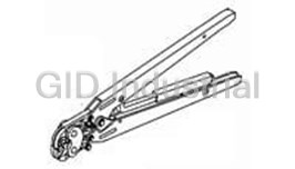
Connector To Terminal Tool With Die Set
58558-1
Part Number
58558-1
Price
Request Quote
Manufacturer
TE CONNECTIVITY
Lead Time
Request Quote
Category
Tools and Supplies » Assembly Tools
Specifications
Manufacturer
TE Connectivity
Manufacturers Part #
58558-1
Industry Aliases
58558-1
Sub-Category
Electronics Assembly Tools
Brand
AMP
Factory Pack Quantity
1
Datasheet
DDEController?Action=showdoc&DocId=Specification+Or+Standard%7F408-4091%7FB%7Fpdf%7FEnglish%7FENG_SS_408-4091_B.pdf
263 KiB

Extracted Text
5:;9<*;065#/,,; & )#%(#&!’’$** %$- ,#+"# ** %$-’",= <4<3(;0=,9(<4($0:69+,9:*(59,:<3;-964;/,796365.,+<:,6-4(5<(33@76>,9,+/(5+;663:(5+;663:(9,05;,5+,+-696**(:065(3<:,(5+36>=63<4, (7730*(;065:>0+,:,3,*;0656-76>,9,+(7730*(;065,8<074,5;-69,?;,5+,+<:,796+<*;06567,9(;065:0:(=(03()3, 6*(;69(5+ #;(;065(9@ #;9(0./;,5,9 (> ::,4)3@ (*26-663$ &09,#0+, !" "!"(5+ 0,::,4)3@ 904705.663$::,4)3@ 9(4, 6=05. (> "(;*/,; +1<:;4,5; &/,,3 #;(;065(9@ $/,!" "!"(5+904705.663$0:(A644,9*0(3.9(+,;663(5+(5+3, 0:+,:0.5,+7904(903@-69-0,3+05:;(33(;0659,7(094(05;,5(5*,>69269 796;6;@705.0505+<:;90(3*644,9*0(36905:;0;<;065(3(7730*(;065:!96+<*; *9047,+>0;/;/0:;663>0334,,;;/,*9047/,0./;9,8<09,4,5;-69/(5+;663:05 ;/,(7796790(;,(7730*(;065:7,*0-0*(;065)<;4(@56;*6473@>0;/6;/,9 6=05. -,(;<9,7(9(4,;,9:6-;/,:7,*0-0*(;065@*6$3,*;9650*:-,9:6-(=(90,;@6- (5+3,;663:;6:(;0:-@@6<97,9-694(5*,9,8<09,4,5;:69(++0;065(305-694(;065 *65;(*;;/,,*/50*(3$::0:;(5*,,5;,9(; Figure 1 Reasons for reissue are provided in Section 9, REVISION SUMMARY. PRO–CRIMPER III Hand Crimping Tool Assembly 58558–1 consists of Die Assembly 58558–2 and 0.<9,:(5+ PRO–CRIMPER III Hand Crimping Tool Frame 354940–1. The hand tool assembly is used to crimp The hand tool assembly features a tool frame with a Consumer RF Series BNC Plug Connectors onto stationary jaw and handle, a moving jaw, a moving various sizes of RG/U cable. handle, and an adjustable ratchet that ensures full contact crimping. The tool frame holds a die assembly For additional information on the hand tool frame, with four crimping chambers. The die assembly refer to 408–9930. features an indenter die and an anvil die. Attached to the outside of the frame is a locator and Read these instructions thoroughly before using the straightener assembly, which properly positions and hand tool assembly. holds the connector center contact during crimping. Die retaining pins and die retaining screws are used to position and secure the dies in the tool frame. A nut is used on the upper die retaining screw to hold the locator and straightener assembly in place. $###$$"$/0:*65;9633,++6*<4,5;0::<)1,*;;6*/(5.,@*6$3,*;9650*:69769(;065(990:)<9.!6- 335;,95(;065(3"0./;:",:,9=,+!" %$$ "693(;,:;9,=0:065(5+",.065(3<:;64,9#,9=0*, $36.6(5+@*6$3,*;9650*:(9,;9(+,4(92:=0:0;6<9>,):0;,(;+-’ $ +)’&#*’%,,, 9(+,4(92$ ;/,9796+<*;:36.6:(5+*647(5@5(4,:<:,+(9,;/,7967,9;@6-;/,099,:7,*;0=,6>5,9: ’!*$&)$’#((%++"& %, #!"" % " " #" " " " ! " " %! $ Figure 2 engaged sufficiently to hold the dies in place, then tighten both die retaining screws. # 1. Close the tool handles until the ratchet releases, then allow the handles to open fully. 2. Remove the two die retaining screws from the 6. Attach the straightener onto the spring retainer tool jaws. with the adjustment screw. Insert the spring into the spring retainer and place the locator over the 3. Install the anvil die in the movable jaw of the tool spring. frame. Insert the short die retaining screw through the retaining hole in the jaw and through the anvil 7. While holding the locator against the spring die. Tighten the screw just enough to hold the die retainer, place the screw hole in the spring retainer in place. Do not tighten the screw completely at over the end of the long die retaining screw. The this time. locator should be against the side of the tool jaw. 4. Install the indenter die in the stationary jaw of 8. Place the nut onto the end of the long die the tool frame. Insert the long die retaining screw retaining screw and tighten the nut enough to hold through the retaining hole in the jaw and through the locator and straightener assembly in place, but the indenter die. Tighten the screw just enough to still allowing the locator to slide up and down. hold the die in place. Do not tighten the screw 9. To disassemble, close the tool handles until the completely at this time. ratchet releases. Remove the nut, the locator and 5. Carefully close the tool handles, making sure straightener assembly, and the two die retaining that the dies align properly. Continue closing the screws. Slide the anvil and indenter out of the tool tool handles until the ratchet in the tool frame has jaws. &" ! "$ &)#%(#&!’’$** %$- 4. Insert stripped cable into contact wire barrel until it is butted against the locator. See cross–sectional view in Figure 3. )*&&# )’(&, - *%*(&%**)+’’&(* !+)*$%*%&%%*&((*%* &%&( ")+(**&*) )&*- (((#(&(!+)*$%**+(% * ##.*%*( )*(*,%#. %*&*( $’ %$(& &%**)+’’&(*%*(*%* &%&()&+# **$’**&( $’% $’(&’(#.’&) * &% ,( ))’ %* &% %*(&%** % * &% 5. Holding the cable in position, close the tool &(+) %**&&#*&( $’) (&%%*&() handles until the ratchet releases. Allow the tool handles to open fully and remove the crimped For detailed information on cable strip lengths and center contact from the dies. proper assembly of the connector, refer to the instructions packaged with the connector. Make sure( $’%*(&%**$.)* " %* that the connector ferrule has been placed onto the( $’ %(+**&%**%) #. cable, and that the cable braided shield is flared away($&,.’+) %&-%-(&%**&’&* from the cable. Then proceed as described in 4.1,#&*&() +( and 4.2. )#%(#&!+" )),$ " )#%(#&!+" &+ )’&++" 1. Insert the crimped center contact into the connector body until the cable dielectric butts 1. Holding the center contact by the mating end, against the dielectric inside the connector body or insert the contact through the front of the tool and until the center contact is securely positioned into the appropriate crimping chamber of the within the connector. Make sure that the braided anvil die. shield is over the support sleeve of the connector body and that no strands from the shield enter the 2. Close the tool handles so that the dies partially connector body. close. Position the contact so that the locator drops into the contact wire stop slot and the end of the 2. Slide the ferrule up over the braided shield and contact is inside the groove in the straightener. See onto the connector until the ferrule butts against cross–sectional view in Figure 3. the shoulder on the connector body. 3. Hold the contact in place and squeeze the tool 3. Place the ferrule in the appropriate crimping handles together until the ratchet engages just chamber of the anvil die so that the shoulder on enough to hold the contact in place. Do not deform the connector body butts against the edge of the contact wire barrel. the die. ! ! ! ! !! ! !! !! ! !! # !! !! !# ! !! ! Figure 3 #$! ! #& "% #$$!’’"!( 5. Remove and inspect the center contact. 6. Make another sample crimp. If the contact is still being bent during crimping, repeat the adjustment procedure. # The frame assembly ratchet mechanism features an adjustment wheel with numbered settings. If the crimp height or retention force is not acceptable, adjust the ratchet as follows: # " & #""!!" # 1. Remove the lockscrew from the ratchet adjustment wheel.$ 2. With a screwdriver, adjust the ratchet wheel Figure 4 from the opposite side of the frame. 3. Observe the ratchet adjustment wheel. If a tighter crimp is required, rotate the adjustment wheel COUNTERCLOCKWISE to a higher–numbered setting. If a looser crimp is required, rotate the adjustment wheel CLOCKWISE to a lower–numbered setting. 4. While holding the assembly together, begin to close the tool handles. Keep holding the assembly 4. Replace the lockscrew. until the dies have closed enough to hold the assembly in place. 5. Make a sample crimp and measure the crimp height. If the crimp height is acceptable, secure the 5. Carefully close the tool handles until the ratchet lockscrew. If the dimension is unacceptable, releases. remove lockscrew and continue to adjust the ratchet, and again measure a sample crimp. 6. Allow the tool handles to open fully and remove the crimped connector from the dies. % $ Make a sample crimp and determine if the center contact is bending upward, bending downward, or bending from side to side. If the contact is bent, adjustment is required. 1. Loosen the adjustment screw. 2. Place a center contact with cable into the proper "" crimping chamber and close the tool handles until #!"" the locator and straightener assembly is holding the contact in position. 3. Move the straightener up or down, as required,! % to eliminate the bending of the center contact.& 4. Tighten the adjustment screw and close the Figure 5 handles until the ratchet releases. &" ! "$ #-&0*,/*-(..+11’,$+4 #*-2’-#-%’ 1. Remove dust, moisture, and other contaminants with a clean, soft brush, or a clean, soft, lint–free cloth. Do NOT use any objects that could damage the dies or tool. 2. Make sure that the proper die retaining screws are properly secured. 3. When the dies are not in use, mate and store them in a clean, dry area. 4. Store the tool with the tool handles closed to prevent objects from becoming lodged within the jaws. " -1/’%2*.- 1. Remove all lubrication and accumulated film from the dies by immersing the dies in a suitable Figure 6 commercial degreaser. 2. Make certain that all die retaining screws and !die components are properly secured. Since the previous of this instruction sheet, the 3. Inspect the crimping surfaces for flattened, following changes were made: chipped, worn, or cracked areas. If damage is evident, the dies must be replaced. Refer to PRO–CRIMPER II Hand Tool was changed to Section 8, DIE REPLACEMENT. PRO–CRIMPER III Hand Tool, The TE logo was applied, and ’#130*-(2)’*’/’-*-( The format was updated to the current The die assembly will perform correctly as long as: corporate requirements. (1) the product specified is correct for the application, (2) the specific die assembly is used, (3) the die assembly has been measured to ensure that the openings are correct, and (4) the tool has been adjusted correctly. Figure 6 provides information on die opening sizes. Customer–replaceable parts are shown in Figure 1. Available separately, PRO–CRIMPER III Hand Crimping Tool Repair Kit 679221–1 includes a replacement nut and a variety of pins, rings, screws, and springs. If the dies are damaged or worn excessively, they must be replaced. Order the repair kit and replaceable parts through your Tyco Electronics representative, or call 1–800–526–5142, or send a facsimile of your purchase order to 1–717–986–7605, or write to: CUSTOMER SERVICE (38–35) TYCO ELECTRONICS PO BOX 3608 HARRISBURG PA 17105–3608 !"
Frequently asked questions
How does Electronics Finder differ from its competitors?

Is there a warranty for the 58558-1?
Which carrier will Electronics Finder use to ship my parts?
Can I buy parts from Electronics Finder if I am outside the USA?
Which payment methods does Electronics Finder accept?
Why buy from GID?

Quality
We are industry veterans who take pride in our work

Protection
Avoid the dangers of risky trading in the gray market

Access
Our network of suppliers is ready and at your disposal

Savings
Maintain legacy systems to prevent costly downtime

Speed
Time is of the essence, and we are respectful of yours
Related Products

Torque Wrenches Are Used To Properly Install Or Disassemble The Connectors 1055419-1
Tool For RF Connectors 1055442-1
Tool For RF Connectors 1055443-1
Insertion Tool For RF Connectors 1055447-1
Insertion Tool For RF Connectors 1055448-1
Assembly Tools, Sma Right Angle Cable Plugs 1055451-1
Request a Quote

The quote request has been received
Close

Facing challenges or have inquiries? Feel free to contact us!
Call Us +1-469-283-2440
What they say about us
FANTASTIC RESOURCE
One of our top priorities is maintaining our business with precision, and we are constantly looking for affiliates that can help us achieve our goal. With the aid of GID Industrial, our obsolete product management has never been more efficient. They have been a great resource to our company, and have quickly become a go-to supplier on our list!
Bucher Emhart Glass
EXCELLENT SERVICE
With our strict fundamentals and high expectations, we were surprised when we came across GID Industrial and their competitive pricing. When we approached them with our issue, they were incredibly confident in being able to provide us with a seamless solution at the best price for us. GID Industrial quickly understood our needs and provided us with excellent service, as well as fully tested product to ensure what we received would be the right fit for our company.
Fuji
HARD TO FIND A BETTER PROVIDER
Our company provides services to aid in the manufacture of technological products, such as semiconductors and flat panel displays, and often searching for distributors of obsolete product we require can waste time and money. Finding GID Industrial proved to be a great asset to our company, with cost effective solutions and superior knowledge on all of their materials, it’d be hard to find a better provider of obsolete or hard to find products.
Applied Materials
CONSISTENTLY DELIVERS QUALITY SOLUTIONS
Over the years, the equipment used in our company becomes discontinued, but they’re still of great use to us and our customers. Once these products are no longer available through the manufacturer, finding a reliable, quick supplier is a necessity, and luckily for us, GID Industrial has provided the most trustworthy, quality solutions to our obsolete component needs.
Nidec Vamco
TERRIFIC RESOURCE
This company has been a terrific help to us (I work for Trican Well Service) in sourcing the Micron Ram Memory we needed for our Siemens computers. Great service! And great pricing! I know when the product is shipping and when it will arrive, all the way through the ordering process.
Trican Well Service
GO TO SOURCE
When I can't find an obsolete part, I first call GID and they'll come up with my parts every time. Great customer service and follow up as well. Scott emails me from time to time to touch base and see if we're having trouble finding something.....which is often with our 25 yr old equipment.
ConAgra Foods