

 Manufacturers
TE CONNECTIVITY 59836-1
Description
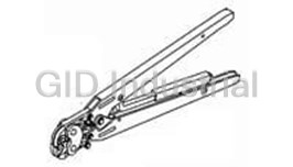
Tool For SL 156 Housings And Contacts For Large Insulation Diameter Wire
59836-1
Part Number
59836-1
Price
Request Quote
Manufacturer
TE CONNECTIVITY
Lead Time
Request Quote
Category
Tools and Supplies » Assembly Tools
Specifications
Manufacturer
TE Connectivity
Manufacturers Part #
59836-1
Industry Aliases
59836-1
Sub-Category
Electronics Assembly Tools
Brand
AMP
Factory Pack Quantity
1
Datasheet
DDEController?Action=showdoc&DocId=Data+Sheet%7F82056_MTA%7F0608%7Fpdf%7FEnglish%7FENG_DS_82056_MTA_0608.pdf
4778 KiB

Extracted Text
CONNECTORS/ APPLIANCES MTA, CST-100 II and SL-156 Connectors APPLIANCES /// MTA, CST-100 II AND SL-156 CONNECTORS Contents Introduction Introduction and Table of Contents ......................................................................................2, 3 Connector Selection Guide ..............................................................................................................3 This catalog has been designed to assist you, our customer, identify products to .100 [2.54] Centerline Connectors satisfy your connector needs for printed MTA-100 IDC Connectors and Headers ..................................................................................4-23 circuit board headers, mass termination Introduction ......................................................................................................................................... 4 connectors preloaded with contacts, Wire-to-Board Mateability Guide ............................................................................................5, 6 crimp-snap contacts and housings, and Connectors—UL94V-2 and UL94V-0 card edge connectors with preloaded Closed End with and without Polarizing Tab ................................................................. 7, 8 contacts. The list at right identifies by Feed-Thru with and without Polarizing Tab .................................................................... 7, 8 centerline the types of product available LED Closed End and Feed-Thru—UL94V-2 ..................................................................... 7, 8 and is meant to be of assistance to you in Accessories ....................................................................................................................................9, 10 the product selection process. Posted Connectors Mateability Guide .................................................................................11, 12 MTA-100 Posted Connectors (Wire-to-Wire) UL94V-2 Closed End ......................................................................................................................................13 Feed-Thru ........................................................................................................................................13 Headers—UL94V-0 Flat—Straight and Right-Angle Posts ...................................................................................14 Narrow Flat—Straight and Right-Angle Posts ...................................................................15 Polarized—Straight and Right-Angle Posts........................................................................16 Friction Lock—Straight and Right-Angle Posts ................................................................ 17 IDC Headers with Retention Peg—Straight Posts ....................................................................18 MTA-100 High Profile Headers—Right-Angle Posts ...........................................................................19 Polarized—High Temperature, Straight and Right-Angle Posts ................................20 Friction Lock—High Temperature, Straight and Right-Angle Posts .........................21 Polarized—Surface Mount, Straight ...................................................................................... 22 Friction Lock—Surface Mount, Straight ............................................................................. 22 Shrouded—Straight and Right-Angle Posts ......................................................................23 CST-100 II Crimp Contacts, Housings and Shrouded ....................................................24, 25 .156 [3.96] Centerline Connectors Crimp MTA-156 IDC Connectors and Headers ................................................................................26-46 CST-100 II Introduction .......................................................................................................................................26 Wire-to-Board Mateability Guide ....................................................................................... 27, 28 Connectors—UL94V-2 and UL94V-0 Closed End with Locking Ramp, with and without Polarizing Tabs ........................29 Closed End without Locking Ramp, with and without Polarizing Tabs .................30 Feed-Thru with Locking Ramp, with and without Polarizing Tabs ...........................31 Feed-Thru without Locking Ramp, with and without Polarizing Tabs ....................32 Accessories ................................................................................................................................. 33-35 Posted Connectors Mateability Guide ..............................................................................36, 37 MTA-156 Posted Connectors (Wire-to-Wire)—UL94V-2 IDC Closed End .....................................................................................................................................38 MTA-156 Feed-Thru .......................................................................................................................................38 MTA-156 Headers—UL94V-0 Flat—Straight Posts ....................................................................................................................39 Flat—Right-Angle Posts ........................................................................................................... 40 Friction Lock—Straight Posts ..................................................................................................41 Friction Lock—Right-Angle Posts .........................................................................................42 Polarized Lock—Straight Posts ..............................................................................................43 Polarized Lock—Right-Angle Posts ......................................................................................44 Friction Lock—High Temperature, Straight Posts ...........................................................45 Shrouded—Straight and Right-Angle Posts ......................................................................46 PAGE 2 Contents (continued) SL-156 Crimp Connectors and Headers.................................................................................47-51 Wire-to-Board Mateability Guide ..............................................................................................47 Wire-to-Board Crimp Contacts and Keying Plugs ..............................................................48 Wire-to-Board Housings—UL94V-0 .........................................................................................49 Housings with Through Board Latch—UL94V-2 ..................................................................50 Housings and Contacts for Large Insulation Diameter (LID) Wire ................................51 Crimp SL-156 MTA Wire Selection and Ribbon Cable Preparation .................................................................52 IDC Ribbon Cable .............................................................................................................................. 53-56 Need More Information? MTA Wire Termination Flowchart ...................................................................................................... 57 Call Technical Support at the numbers MTA Application Tooling................................................................................................................. 58-61 listed on the back of this catalog. Technical Support is staffed with special- Part Number Index ............................................................................................................................62-64 ists well versed in TE products. They can Global Contacts ........................................................................................................................................65 provide you with: TE Technical Support ..............................................................................................................................66 • Technical support • Catalogs • Technical Documents • Product Samples • Authorized Distributor Locations CONNECTOR SELECTION GUIDE Product Name .100" Centerline MTA-100 IDC .100 .060* -55 to V-0 & Connectors IDC Planned 2-28 28-22 5 250 Yes 2.54 1.52 +105 V-2 and Headers CST-100 II .100 .065 -55 to Contacts and Crimp Planned 2-28 26-22 4 250 V-0 Yes 2.54 1.65 +105 Housings .156" Centerline MTA-156 .156 .095* -55 to V-0 & Connectors IDC Yes 2-24 16-18 7 600 Yes 3.96 2.41 +105 V-2 and Headers 1-24; SL-156 2-10 w/ .156 .105 -25 to Contacts and Crimp No through 24-18 10 250 V-0 Yes 3.96 2.67 +105 Housings board latch SL-156 Large Ins. Dia. (LID) .156 .112 -25 to Crimp No 2-24 24-16 10 250 V-0 Yes Contacts and 3.96 2.84 +105 Housings *When terminated one position at a time. **Current Rating is application dependent. PAGE 3 Centerline Contact Termination Wire-to-Wire Options No. of Positions Wire Size (AWG) Wire Insulation Dia. Max. Current Rating (A)** Voltage Rating Max. (VAC) Operating Temp. Range (°C) UL Flammability Replacement Contacts Approvals MTA, CST-100 II and SL-156 Connectors .100 [2.54] Centerline MTA-100 IDC Connectors and Headers PRODUCT FACTS • Connectors and headers for 2 through 28 positions; wire sizes of 22, 24, 26 2 and 28 AWG [0.4-0.08 mm ] • Wire-to-Post Connectors preloaded with dual beam contacts • Connectors and headers, except shrouded headers, are end-to-end stackable • Connector styles include both closed end and feed thru connectors with locking ramps, with and without polarizing tabs • Molded ribs on housing do not allow reverse mating • Posted connectors for 2 through 19 positions • Connectors preloaded with IDC contacts • All contacts are slotted for insulation displacement (IDC) terminal technique • Contacts are lubricated for fretting corrosion protection • Benefits derived from the MTA-100 system include increased quality and ease of handling such as: • One-step assembly • No wire stripping • No contact damage • Reduced wiring errors • Simpler tooling • Simple maintenance and repair • Meets the material requirements of Table 23.1 of UL1410 Standards for Television Receiver and Video Products (wire-to post connectors only) • Recognized under the Component Performance Data* [1.27] for mass termination of wires. Tin Program of Underwriters Labora- plated solid, fused stranded, or stranded Voltage Rating—250 vac tories Inc., File No. E28476 (7 strands) wire with PVC insulation can • Certified by Canadian Standards 2 Current Rating—5 amp max. be used on 22–28 AWG [0.4–0.9 mm ] Association, File No. LR7189 MTA-100 connectors and 19 stranded wire Low-Level Resistance— 2 on 22–24 AWG [0.4–0.2 mm ] MTA-100 6 mΩ max. initial Technical Documents Product connectors. Only one wire to be terminat- Specification Dielectric Withstanding Voltage— ed into an IDC contact slot. 750 vac/1 min. 108-1050 MTA-100 Connectors The wire-to-post connector housing Insulation Resistance— Application Specifications material is flame retardant thermoplastic, 5000 MΩ min. initial 114-1019 MTA-100 Connectors either UL94V-2 or UL94V-0 rated. Operating Temperature— 114-1031 MTA-100 Ribbon Cable A full line of .100 [2.54] centerline head- -55° C to +105° C Assembly ers completes the system. Headers are available with straight or right-angle MTA-100 connectors accept discrete Note: Refer to page 52 for approved wire listings. posts, in flat, polarized or friction lock and ribbon cable wire sizes ranging from 2 styles. Headers are available in 2 through 22–28 AWG [0.4–0.08 mm ] with maxi- *Refer to the Product Specification for additional 28 positions. Shrouded headers are avail- mum insulation outside diameter of .060 electrical, mechanical and environmental performance able in 2 through 14 positions. tests and requirements. [1.52] for terminating single wire and .050 PAGE 4 MTA, CST-100 II and SL-156 Connectors MTA-100 Connector/Header Mateability Guide This matrix has been prepared to assist you, our customer, in defining the correct mating halves for the MTA-100 header and connector combination. Where a “Y” is indicated the combination is a valid mating pair. Where an “N” is indicated the combination is not acceptable for mating. Headers 640440 YYYYYYYYYYYYYYYYYYN NNYYYYYYYYYYYY Matrix for 640441 YYYYYYYYYYYYYYYYYYN NNYYYYYYYYYYYY Tin Plated 640442 YYYYYYYYYYYYYYYYYYN N NYYYYYYYYYYYY Part Numbers 640443 YYYYYYYYYYYYYYYYYYN NNYYYYYYYYYYYY 640468 YYYYYYYYYYYYYYYYYYN NNYYYYYYYYYYYY 640469 YYYYYYYYYYYYYYYYYYN N NYYYYYYYYYYYY 640470 YYYYYYYYYYYYYYYYYYN N NYYYYYYYYYYYY 640471 YYYYYYYYYYYYYYYYYYN NNYYYYYYYYYYYY 640620 YYYYYYYYYYYYYYYYYYN NNYYYYYYYYYYYY 640621 YYYYYYYYYYYYYYYYYYN N NYYYYYYYYYYYY 640622 YYYYYYYYYYYYYYYYYYN NNYYYYYYYYYYYY 640623 YYYYYYYYYYYYYYYYYYN NNYYYYYYYYYYYY 641311 YYYYYYYYYYYYYYYYYYN N NYYYYYYYYYYYY 641312 YYYYYYYYYYYYYYYYYYN N NYYYYYYYYYYYY 641313 YYYYYYYYYYYYYYYYYYN NNYYYYYYYYYYYY 641314 YYYYYYYYYYYYYYYYYYN NNYYYYYYYYYYYY 641534 YYYYYYYYYYYYYYYYYYN NNYYYYYYYYYYYY 641535 YYYYYYYYYYYYYYYYYYN NNYYYYYYYYYYYY 641536 YYYYYYYYYYYYYYYYYYN NNYYYYYYYYYYYY 641537 YYYYYYYYYYYYYYYYYYN NNYYYYYYYYYYYY 641653 YYYYYYYYYYYYYYYYYYN NNYYYYYYYYYYYY 641654 YYYYYYYYYYYYYYYYYYN NNYYYYYYYYYYYY 641655 YYYYYYYYYYYYYYYYYYN NNYYYYYYYYYYYY 641656 YYYYYYYYYYYYYYYYYYN NNYYYYYYYYYYYY 643498 YYYYYYYYYYYYYYYYYYN NNYYYYYYYYYYYY 643813 YYYYYYYYYYYYYYYYYYN NNYYYYYYYYYYYY 643814 YYYYYYYYYYYYYYYYYYN NNYYYYYYYYYYYY 643815 YYYYYYYYYYYYYYYYYYN NNYYYYYYYYYYYY 643816 YYYYYYYYYYYYYYYYYYN NNYYYYYYYYYYYY 643828 YYYYYYYYYYYYYYYYYYN NNYYYYYYYYYYYY 644083 YYYYYYYYYYYYYYYYYYN NNYYYYYYYYYYYY 644312 YYYYYYYYYYYYYYYYYYN NNYYYYYYYYYYYY 644313 YYYYYYYYYYYYYYYYYYN NNYYYYYYYYYYYY 644497 YYYYYYYYYYYYYYYYYYN NNYYYYYYYYYYYY 644511 YYYYYYYYYYYYYYYYYYN NNYYYYYYYYYYYY 644512 YYYYYYYYYYYYYYYYYYN NNYYYYYYYYYYYY 644513 YYYYYYYYYYYYYYYYYYN NNYYYYYYYYYYYY 644514 YYYYYYYYYYYYYYYYYYN NNYYYYYYYYYYYY 644540 YYYYYYYYYYYYYYYYYYN NNYYYYYYYYYYYY 644563 YYYYYYYYYYYYYYYYYYN NNYYYYYYYYYYYY 644564 YYYYYYYYYYYYYYYYYYN NNYYYYYYYYYYYY 644565 YYYYYYYYYYYYYYYYYYN NNYYYYYYYYYYYY 644574 YYYYYYYYYYYYYYYYYYN NNYYYYYYYYYYYY 644575 YYYYYYYYYYYYYYYYYYN NNYYYYYYYYYYYY 644576 YYYYYYYYYYYYYYYYYYN NNYYYYYYYYYYYY 644577 YYYYYYYYYYYYYYYYYYN NNYYYYYYYYYYYY 644578 YYYYYYYYYYYYYYYYYYN NNYYYYYYYYYYYY 644579 YYYYYYYYYYYYYYYYYYN NNYYYYYYYYYYYY 644795 YYYYYYYYYYYYYYYYYYN NNYYYYYYYYYYYY *1375820 YYYYYYYYNNYYNNYYYYY YYYYYYYYYYYYYY *Select contact plating to match header plating. PAGE 5 640452 640453 640454 640455 640456 640457 644456 644457 644486 644488 644694 644695 644803 644861 644874 644875 644876 644877 644892 644893 644894 647047 647048 647050 647051 647106 647166 647502 647531 647609 647623 647532 1744075 Connectors MTA, CST-100 II and SL-156 Connectors MTA-100 Connector/Header Mateability Guide (continued) This matrix has been prepared to assist you, our customer, in defining the correct mating halves for the MTA-100 header and connector combination. Where a “Y” is indicated the combination is a valid mating pair. Where an “N” is indicated the combination is not acceptable for mating. Headers Matrix for 641237 YYYYYYYYYYYYNNNYYY YYYYYYYY .000030 641238 YYYYYYYYYYYYNNNYYY YYYYYYYY [0.00076] 641239 YYYYYYYYYYYYNNNYYY Y YYYYYYY Gold Plated 641240 YYYYYYYYYYYYNNNYYY YYYYYYYY 641241 YYYYYYYYYYYYNNNYYY YYYYYYYY Part Numbers 641242 YYYYYYYYYYYYNNNYYY Y YYYYYYY 641243 YYYYYYYYYYYYNNNYYY Y YYYYYYY 641244 YYYYYYYYYYYYNNNYYY YYYYYYYY 644020 YYYYYYYYYYYYNNNYYY YYYYYYYY 644042 YYYYYYYYYYYYNNNYYY Y YYYYYYY 644043 YYYYYYYYYYYYNNNYYY YYYYYYYY 644044 YYYYYYYYYYYYNNNYYY YYYYYYYY 644702 YYYYYYYYYYYYNNNYYY Y YYYYYYY 644726 YYYYYYYYYYYYNNNYYY Y YYYYYYY *1375820 YYYYYYNNYYYYYYYYYY YYYYYYYY *Select contact plating to match header plating. Headers Matrix for 641190 YYYYYYYYYYYYYYYYYYYYY .000015 641191 YYYYYYYYYYYYYYYYYYYYY [0.00038] 641192 YYYYYYYYYYYYYYYYYYYYY 641193 YYYYYYYYYYYYYYYYYYYYY Gold Plated 641198 YYYYYYYYYYYYYYYYYYYYY Part Numbers 641199 YYYYYYYYYYYYYYYYYYYYY 641200 YYYYYYYYYYYYYYYYYYYYY 641201 YYYYYYYYYYYYYYYYYYYYY 644038 YYYYYYYYYYYYYYYYYYYYY 644040 YYYYYYYYYYYYYYYYYYYYY 647477 YYYYYYYYYYYYYYYYYYYYY 647480 YYYYYYYYYYYYYYYYYYYYY *1375820 NNNNNNNNNNNNNNNNNNNYY 1744020YYYYYYYYYYYYYYYYYYYYY *Select contact plating to match header plating. PAGE 6 641211 641212 641213 641214 641215 641216 644487 644489 641122 644884 641123 644885 641124 644886 641125 644887 641126 644896 641127 644897 644888 644898 644889 647108 644890 647109 644891 647114 647075 647116 647076 647117 647078 647168 647079 647626 647107 647624 647167 647534 647467 1744047 647625 1744163 647627 647533 1744074 Connectors Connectors MTA, CST-100 II and SL-156 Connectors MTA-100 IDC Connectors—Closed End and Feed-Thru Material and Finish ClosedEndConnectors Housing—UL94V-2 rated, nylon, see below for color; or UL94V-0 rated, nylon, .275 [6.99] black A .056 .075 Contacts—Phosphor bronze, post tin [1.42] [1.91] plated, .000030 [0.00076] or .000015 .245 [0.00038] post gold-plated over nickel .275 .184 [6.22] [6.99] [4.67] Color Coding by Wire Size for UL94V-2 .520 .100 Typ. Connectors [13.21] [2.54] 28 AWG—Green WithoutPolarizingTabs 26 AWG—Blue 24 AWG—White 22 AWG—Red .075 [1.91] All wire sizes in UL94V-0—Black .228 [5.80] For mateability options, see matrix on pages 5 and 6. For mating half visuals, see pages 13 thru WithPolarizingTabs 23. Notes: 1. Refer to pages 52-56 for approved wire listing. 2. For strain reliefs and dust covers, see page 9. Feed-ThruConnectors 3. For keying plugs, see page 10. 4. Other circuit sizes are available upon request. .275 A Minimums may apply. [6.99] 5. Connector circuits can be molded closed for keying .075 .056 purposes. Minimums may apply. [1.91] [1.42] 6. Where no part numbers appear in the chart, parts can be made available upon request. Minimums .305 .245 may apply. .184 [7.75] [6.22] [4.67] 7. To determine connector overall length (dim. A), multiply .100 x the number of circuits. Example: .100 x 10 circuits equals 1.000 inch [25.4 mm]. .520 .100 Typ. [2.54] [13.21] WithoutPolarizingTabs .075 [1.91] .228 [5.80] WithPolarizingTabs PAGE 7 MTA, CST-100 II and SL-156 Connectors MTA-100 IDC Connectors—Closed End and Feed-Thru MTA-100 IDC Connectors—Closed End and Feed-Thru (continued) Base Part Numbers Connector Ordering Information Closed End Feed-Thru The “Base Part Numbers” Chart at right Without Tabs With Tabs Without Tabs With Tabs Connector Type shows the base part number, and their & Wire Size Connector RoHS Connector RoHS Connector RoHS Connector RoHS RoHS (Restrictions on Certain Hazard- Part Nos. Equiv. Part Nos. Equiv. Part Nos. Equiv. Part Nos. Equiv. ous Substances) Compliant (lead free) Standard UL94V-2, Tin Plated equivalent available for the described 22 AWG 1 640440 32–58 643813 32–58 640620 32–58 644540 32–45 2 connectors. 0.3–0.4 mm 24 AWG 1 640441 32–58 643814 32–58 640621 32–58 644563 32–54 Prefixes and suffixes are determined by 2 0.2 mm the number of circuit positions in the 26 AWG 1 640442 32–58 643815 32–58 640622 32–58 644564 32–45 2 0.12–0.15 mm connector. For example, the complete 28 AWG 1 2 640443 32–58 643816 32–58 640623 32–58 644565 32–45 part number for a 10-position closed 0.08–0.09 mm end connector without polarizing tabs Tape Mounted on Reel UL94V-2, Tin Plated for 22 AWG wire would be: 22 AWG 640468 32–58 644511 42–68 641311 32–58 — — 2 0.3–0.4 mm Base number 640440 plus 24 AWG 640469 32–58 644512 32–58 641312 32–58 — — prefix-and-suffix 2 0.2 mm 4- — -0 26 AWG 2 640470 32–58 644513 32–58 641313 32–58 — — 0.12–0.15 mm The correct ordering number is 28 AWG 640471 32–58 644514 32–58 641314 32–58 — — 2 4-640440-0 0.08–0.09 mm All part numbers are the RoHS equivalent Standard UL94V-2, .000030 [0.00076] Gold Plated 22 AWG version. Example: 1 641237 32–58 644042 32–58 641241 32–58 644702 32–45 2 0.3–0.4 mm No. of Lead Free 24 AWG 2 641238 32–58 644020 32–58 641242 32–58 — — 0.2 mm Pos. RoHS 26 AWG Prefix/Suffix 1 1 641239 32–58 644043 32–44 641243 32–58 644726 32–45 2 0.12–0.15 mm 2 3-640440-2 28 AWG 1 641240 32–58 644044 32–44 641244 32–58 — — 2 0.8–0.9 mm 3 3-640440-3 4 3-640440-4 Standard UL94V-2, .000015 [0.00038] Gold Plated 5 3-640440-5 22 AWG 1 641190 32–58 644038 32–44 641198 32–58 647477 32–46 2 0.3–0.4 mm 6 3-640440-6 24 AWG 1 641191 32–58 1744020 32–44 641199 32–58 — — 7 3-640440-7 2 0.2 mm 8 3-640440-8 26 AWG 1 641192 32–58 644040 32–44 641200 32–58 647480 32–43 2 0.12–0.15 mm 9 3-640440-9 28 AWG 641193 32–58 — — 641201 32–58 — — 2 10 4-640440-0 0.08–0.09 mm 11 4-640440-1 LED*, UL94V-2, Tin Plated (See Note 1) 12 4-640440-2 22 AWG 641534 32–33 — — 641653 32–33 — — 2 0.3–0.4 mm 13 4-640440-3 24 AWG 14 4-640440-4 641535 32–33 644795 32–33 641654 32–33 — — 2 0.2 mm 15 4-640440-5 26 AWG 641536 32–33 — — 641655 32–33 — — 2 0.12–0.15 mm 16 4-640440-6 28 AWG 17 4-640440-7 641537 32–33 — — 641656 32–33 — — 2 0.08–0.09 mm 18 4-640440-8 Standard UL94V-0, Tin Plated (Gold is available, minimums may apply.) (Black in color) 19 4-640440-9 22 AWG 1 1 1 1 643498 32–45 644083 32–45 644575 32–45 644578 32–45 2 20 5-640440-0 0.3–0.4 mm 24 AWG 21 5-640440-1 1 1 1 1 644574 32–45 644312 32–45 644576 32–45 644579 32–45 2 0.2 mm 22 5-640440-2 26 AWG 1 1 1 1 643828 32–45 644313 32–45 644577 32–45 644497 32–45 2 23 5-640440-3 0.12–0.15 mm 24 5-640440-4 *LED connectors are designed to mate with .014–.020 [0.36–0.51] diameter posts or square leads. 1 Other circuit sizes are available upon request. Minimums may apply. 25 5-640440-5 2 Tape mounted. 26 5-640440-6 Note: :Blocked circuit configurations are available. Contact product engineer or product manager for 27 5-640440-7 details. Minimums may apply. 28 5-640440-8 Note: All RoHS equivalent part numbers may not be available upon catalog release. If the number you need is not available, please contact Product Engineering to expedite your request. PAGE 8 MTA, CST-100 II and SL-156 Connectors Closed End Strain Relief Covers Closed End Dust Covers MTA-100 IDC Connector Accessories .127 .345 [8.76] [3.23] .335 Retention Dimple [8.51] Covers .340 A Closed End Strain Relief Covers Closed End Dust Covers [8.64] .360 .345 .127 Material (RoHS Compliant) [9.14] [3.23] [8.76] .335 .105 Retention Dimple [8.51] [2.67] Strain Relief Cover—UL94V-2 rated, nylon, white A .340 .130 [8.64] A [3.3].360 Dust Covers—UL94V-0 rated, polyester, [9.14] .105 white [2.67] Note: This portion of the front locking bar may or may not be present. .130 A [3.3] Cover Ordering Information Note: This portion of the front locking bar may or may not be present. Feed-Thru Strain Relief Covers Feed-Thru Dust Covers The “Base Part Numbers” Chart at right .127 shows the base part number and number [3.23] .360 of circuits available for the described [9.14] Retention Dimple Feed-Thru Strain Relief Covers Feed-Thru Dust Covers cover. .245 .127 [6.22] A [3.23] .360 Prefixes and suffixes are determined by [9.14] Retention Dimple the number of circuit positions in the .245 .395 [6.22] cover. For example, the complete part [10.03] A number for a 10-position closed end .395 strain relief cover would be: [10.03] .130 A [3.3] Base number 643075 plus prefix-and-suffix .130 A [3.3] 1- — -0 Note: This portion of the front locking bar may or may not be present. The correct ordering number is Note: This portion of the front locking bar 1-643075-0 may or may not be present. Base Part Numbers Base Part Numbers Closed End Feed-Thru Closed End Feed-Thru Strain Relief Dust Strain Relief Dust Covers Strain Relief Covers Dust Covers Strain Relief Covers Dust Covers Covers Covers Covers Cover No. of Cover No. of Cover No. of Cover No. of Cover No. of Cover No. of Cover No. of Cover No. of Part Nos. Circuits Part Nos. Circuits Part Nos. Circuits Part Nos. Circuits Part Nos. Circuits Part Nos. Circuits Part Nos. Circuits Part Nos. Circuits 643075 2–28 640550 2–28 643077 2–28 640642 3-28 643075 2–28 640550 2–28 643077 2–28 640642 3-28 Cover Length Cover Length No. of Dim. Prefix/ No. of Dim. Prefix/ No. of Dim. Prefix/ No. of Dim. Prefix/ No. of Dim. Circuits Prefix/ A No. of Suffix Circuits Dim. Prefix/ A Suffix No. of Circuits Dim. A Prefix/ Suffix No. of Circuits Dim. A Prefix/ Suffix Circuits A Suffix Circuits A Suffix Circuits A Suffix Circuits A Suffix .200 1.600 2.300 .900 23 2- -3 2 -2 9 -9 16 1- -6 5.08 22.86 40.64 58.42 2.300 .200 .900 1.600 16 1- -6 23 2- -3 2 -2 9 -9 5.08 .300 40.64 1.700 58.42 2.400 22.86 1.00 24 2- -4 3 -3 10 1- -0 17 1- -7 7.62 25.4 43.18 60.96 2.400 .300 1.00 1.700 17 1- -7 24 2- -4 3 -3 10 1- -0 1.800 2.500 .400 1.100 7.62 43.18 60.96 25.4 25 2- -5 4 -4 11 1- -1 18 1- -8 10.16 27.94 45.72 63.5 2.500 .400 1.100 1.800 18 1.900 1- -8 25 2.600 2- -5 4 -4 .500 11 1.200 1- -1 26 2- -6 10.16 5 -5 12 1- -2 1945.72 1- -9 63.5 27.94 12.7 30.48 48.26 66.04 2.600 .500 1.200 1.900 2.000 2.700 .600 1.300 19 1- -9 26 2- -6 5 -5 12 1- -2 27 2- -7 6 -6 13 1- -3 20 2- -0 12.7 48.26 66.04 15.24 30.48 33.02 50.8 68.58 2.100 2.700 2.800 .600 .700 1.300 1.400 2.000 28 2- -8 7 -7 14 1- -4 20 21 2- -02- -1 27 2- -7 6 -6 13 1- -3 17.78 35.56 53.34 71.12 15.24 50.8 68.58 33.02 2.200 .800 1.500 2.800 .700 1.400 2.100 8 -8 15 1- -5 22 2- -2 21 2- -1 28 2- -8 7 -7 20.32 14 38.1 1- -4 55.88 17.78 53.34 71.12 35.56 .800 1.500 2.200 22 2- -2 8 -8 15 1- -5 20.32 55.88 38.1 PAGE 9 MTA, CST-100 II and SL-156 Connectors MTA-100 IDC Connector Accessories (continued) .027 Keying Plug with Carrier Strip (10 plugs Sq. [0.69] per strip) Part No. 641994-1 Material (RoHS Compliant) .038 .300 UL94V-2 rated, nylon, natural color [0.97] [7.62] .065 [1.65] .077 [1.96] Note: Removal of contact is not necessary when using .125 keying plug. [3.18] .500 Ref. [12.7] 1.800 Ref. [45.72] Replacement IDC Contacts Part Numbers Wire Size Standard .000030[0.00076] .000015[0.00038] LED 2 Material and Finish AWG mm TinPlated Gold Plated Gold Plated Tin Plated Phosphor bronze, post tin plated; 22 0.3–0.4 640636-3 641186-4 641186-3 641643-2 .000030 [0.00076] or .000015 24 0.2 640637-3 641187-4 641187-3 641644-2 26 0.12–0.15 640638-3 641188-4 641188-3 641645-2 [0.00038] post gold plated over nickel 28 0.08–0.09 640639-3 641189-4 641189-3 641646-2 Note: TE does not recommend terminating an MTA contact more than one time. Use replacement contacts when required for field repairs or wire changes. .452 .075 [11.48] [1.91] .142 Wire Size Part Nos. [3.61] 2 Crimp Snap-In Contacts Max. AWG mm Loose Piece* Strip** .070 26-22 0.12–0.4 640709-2 640708-2 [1.78] Material and Finish *Hand Tool No. 59836-1 (IS 408-6527) Phosphor bronze, tin plated. **Applicator No. 466747-1 (IS 408-8040) .425 [10.8] Special applications for crimp snap-in contacts are: 1. Double wire per contact .070 2. Coax or shielded wire [1.78] 3. Mixed wire size in same connector Note: Only one crimp snap-in contact per connector. PAGE 10 2 MTA, CST-100 II and SL-156 Connectors MTA-100 Connector/Connector Mateability Guide This matrix has been prepared to assist you, our customer, in defining the correct mating halves for the MTA-100 posted connector and connector combination. Where a “Y” is indicated the combination is a valid mating pair. Where an “N” is indicated the combina- tion is not acceptable for mating. Posted Connectors Matrix for 640440 YYYYYYYY Tin Plated 640441 YYYYYYYY Part Numbers 640442 YYYYYYYY 640443 YYYYYYYY 640468 YYYYYYYY 640469 YYYYYYYY 640470 YYYYYYYY 640471 YYYYYYYY 640620 YYYYYYYY 640621 YYYYYYYY 640622 YYYYYYYY 640623 YYYYYYYY 641311 YYYYYYYY 641312 YYYYYYYY 641313 YYYYYYYY 641314 YYYYYYYY 641534 YYYYYYYY 641535 YYYYYYYY 641536 YYYYYYYY 641537 YYYYYYYY 641653 YYYYYYYY 641654 YYYYYYYY 641655 YYYYYYYY 641656 YYYYYYYY 643498 YYYYYYYY 643813 Y* Y* Y* Y* Y* Y* Y* Y* 643814 Y* Y* Y* Y* Y* Y* Y* Y* 643815 Y* Y* Y* Y* Y* Y* Y* Y* 643816 Y* Y* Y* Y* Y* Y* Y* Y* 643828 YYYYYYYY 644083 Y* Y* Y* Y* Y* Y* Y* Y* 644312 Y* Y* Y* Y* Y* Y* Y* Y* 644313 Y* Y* Y* Y* Y* Y* Y* Y* 644497 Y* Y* Y* Y* Y* Y* Y* Y* 644511 Y* Y* Y* Y* Y* Y* Y* Y* 644512 Y* Y* Y* Y* Y* Y* Y* Y* 644513 Y* Y* Y* Y* Y* Y* Y* Y* 644514 Y* Y* Y* Y* Y* Y* Y* Y* 644540 Y* Y* Y* Y* Y* Y* Y* Y* 644563 Y* Y* Y* Y* Y* Y* Y* Y* 644564 Y* Y* Y* Y* Y* Y* Y* Y* 644565 Y* Y* Y* Y* Y* Y* Y* Y* 644574 YYYYYYYY 644575 YYYYYYYY 644576 YYYYYYYY 644577 YYYYYYYY 644578 Y* Y* Y* Y* Y* Y* Y* Y* 644579 Y* Y* Y* Y* Y* Y* Y* Y* 644795 Y* Y* Y* Y* Y* Y* Y* Y* 1375820 NNNNNNNN *2 & 3 position MTA-100 Posted Connectors can not mate with MTA-100 connectors with polarizing tabs. PAGE 11 647000 647001 647002 647003 647004 647005 647006 647007 Connectors MTA, CST-100 II and SL-156 Connectors MTA-100 Connector/Connector Mateability Guide (continued) This matrix has been prepared to assist you, our customer, in defining the correct mating halves for the MTA-100 posted connector and connector combination. Where a “Y” is indicated the combination is a valid mating pair. Where an “N” is indicated the combina- tion is not acceptable for mating. Posted Connectors Matrix for 641237 YYYYYYYY .000030 641238 YYYYYYYY [0.00076] 641239 YYYYYYYY Gold Plated 641240 YYYYYYYY Part Numbers 641241 YYYYYYYY 641242 YYYYYYYY 641243 YYYYYYYY 641244 YYYYYYYY 644020 Y* Y* Y* Y* Y* Y* Y* Y* 644042 Y* Y* Y* Y* Y* Y* Y* Y* 644043 Y* Y* Y* Y* Y* Y* Y* Y* 644044 Y* Y* Y* Y* Y* Y* Y* Y* 644702 Y* Y* Y* Y* Y* Y* Y* Y* 644726 Y* Y* Y* Y* Y* Y* Y* Y* 1375820 NNNNNNNN *2 & 3 position MTA-100 Posted Connectors can not mate with MTA-100 connectors with polarizing tabs. Posted Connectors Matrix for 641190 YYYYYYYY .000015 641191 YYYYYYYY [0.00038] 641192 YYYYYYYY 641193 YYYYYYYY Gold Plated 641198 YYYYYYYY Part Numbers 641199 YYYYYYYY 641200 YYYYYYYY 641201 YYYYYYYY 644038 Y* Y* Y* Y* Y* Y* Y* Y* 644040 Y* Y* Y* Y* Y* Y* Y* Y* 647477 Y* Y* Y* Y* Y* Y* Y* Y* 644726 Y* Y* Y* Y* Y* Y* Y* Y* 647480 Y* Y* Y* Y* Y* Y* Y* Y* 1375820 NNNNNNNN 1744020 YYYYYYYY *2 & 3 position MTA-100 Posted Connectors can not mate with MTA-100 connectors with polarizing tabs. PAGE 12 647008 647009 647010 647011 647012 647013 647014 647015 647008 647009 647010 647011 647012 647013 647014 647015 Connectors Connectors MTA, CST-100 II and SL-156 Connectors MTA-100 IDC Posted Connectors (Wire-to-Wire)—Closed End, Feed-Thru Closed End Feed-Thru Material and Finish Housing—UL94V-2 rated, nylon, see chart for color B B Contacts—Copper alloy, post tin or gold Dim. Dim. plated over nickel (see chart) Note: 1. Mating half visuals — pages 7 & 8. 2. Use feed thru strain relief covers & feed .843 .843 thru dust covers (if needed)—page 9. [21.40] [21.40] 3. Approved wire listing—pages 52-56. .079 .079 [2.00] A Dim. [2.00] A Dim. .025 .025 .303 .303 Sq. Sq. [0.54] [0.54] [7.70] [7.70] .415 .415 [10.54] [10.54] .100 .100 Typ. Typ. [2.54] [2.54] Base Part Numbers Connector Ordering Information Closed End Connector Feed-Thru Connector Connector Type & Wire Size Part Nos. RoHS Equiv. Part Nos. No. of Circuits The “Base Part Numbers” Chart at right Standard UL 94V-2, Tin Plated shows the base part number. 22 AWG 1 2 647000 32–49 647004 — 2 0.3–0.4 mm Prefixes and suffixes are determined by 24 AWG 1 2 647001 32–49 647005 — 2 the number of circuit positions in the 0.2 mm 26 AWG 1 2 connector. For example, the complete 647002 32–49 647006 — 2 0.12–0.15 mm part number for a 12-position closed end 28 AWG 1 2 647003 32–49 647007 — 2 0.08–0.09 mm connector for 22 AWG wire would be: Standard UL 94V-2, .000030 [0.00076] Gold Plated Base number 647000 plus 22 AWG 1 2 2 647008 32–49 647012 — 0.3–0.4 mm prefix-and-suffix 24 AWG 1 4- — -2 2 647009 32–49 647013 — 2 0.2 mm The correct ordering number is 26 AWG 1 2 647010 32–49 647014 — 2 0.12–0.15 mm 4-647000-2 28 AWG 1 2 647011 32–49 647015 — 2 All part numbers are the RoHS equivalent 0.08–0.09 mm version. Example: Standard UL 94V-2, .000015 [0.00038] Gold Plated 22 AWG 1 2 647016 32–49 647020 — No. of Lead Free 2 0.3–0.4 mm Pos. RoHS 24 AWG 1 2 647017 32–49 647021 — 2 0.2 mm Prefix/Suffix 26 AWG 1 2 647018 32–49 647022 — 2 2 3-647000-2 0.12–0.15 mm 28 AWG 1 2 thru 647019 32–49 647023 — 2 0.08–0.09 mm 19 4-647000-9 1 2 and3 position MTA-100 Posted Connectors (Closed End) can not mate with MTA-100 connectors with polarizing tabs. 2 Parts may be manufactured upon request. Minimums may apply. Contact product engineer or product manager for details. See page 8 for an explanation of RoHS lead free equivalents. Dim. Dim. Dim. Dim. No. of No. of No. of No. of Circuits Circuits Circuits Circuits Note: All RoHS equivalent part numbers may not be A B A B A B A B available upon catalog release. If the number you need .300 .227 .700 .627 1.100 1.027 1.500 1.427 2 6 10 14 [7.62] [5.77] [17.78] [15.93] [27.94] [26.09] [38.10] [36.25] is not available, please contact Product Engineering to .400 .327 .800 .727 1.200 1.127 1.600 1.527 expedite your request. 3 7 11 15 [10.16] [8.31] [20.32] [18.47] [30.48] [28.63] [40.64] [38.79] .500 .427 .900 .827 1.300 1.227 1.700 1.627 4 8 12 16 Color Coding by Wire Size for UL94V-2 [12.70] [10.85] [22.86] [21.01] [33.02] [31.17] [43.18] [41.33] .600 .527 1.000 .927 1.400 1.327 1.800 1.727 Connectors 5 9 13 17 [15.24] [13.39] [25.40] [23.55] [35.56] [33.71] [45.72] [43.87] 22 AWG—Red 1.900 1.827 18 [48.26] [46.41] 24 AWG—White 2.000 1.927 19 26 AWG—Blue [50.80] [48.95] Technical Documents 28 AWG—Green Product Specification 108-1050-1 MTA-100 Posted Performance Data Part Numbers Connector Voltage Rating—250 vac Wire Size Tin .000030 Application Specification 2 AWG mm Plated [.00076] Current Rating—5 amp max. 114-1019 MTA-100 Gold Plated .770 [19.55] Low-Level Resistance—6 mΩ max. initial Connectors .075 22 0.3-0.4 3-647030-1 3-647030-2 [1.91] 24 0.2 3-647031-1 3-647031-2 Replacement IDC Dielectric Withstanding Voltage— 26 0.12-0.15 3-647032-1 3-647032-2 Contacts 750 vac/1 min. .083 .025 28 0.8-0.9 3-647033-1 3-647033-2 Material and Finish [2.10] [0.64] Insulation Resistance—5000 MΩ min. initial Contacts—Copper alloy, post Operating Temperature—-55° C to +105° C tin or gold plated over nickel PAGE 13 MTA, CST-100 II and SL-156 Connectors MTA-100 Flat Headers—Straight and Right-Angle Material and Finish StraightPost(.025[0.64]Square) Right-AnglePost(.025[0.64]Square) Housing—UL94V-0 rated, polyester, white Contacts—Copper alloy, tin plated, Post No. 1 .000030 [0.00076] or .000015 [0.00038] gold over nickel .200 [5.08] A Note: .200 .100 1. Post(s) can be omitted for keying purposes. [5.08] .025 [2.54] [0.64] .050 Typ. Specify the desired post(s) to be omitted Sq. [1.27] using the figure to identify Post No. 1. A Typ. .062 .100 2. Gold headers are duplex plated, gold on .140 [1.57] .295 Post No. 1 [2.54] [3.56] mating end of post and tin on the solder tail. [7.49] .535 Ref. 3. To determine header overall length (dim. A) [13.59] multiply .100 x the number of posts. Example: .100 x 10 posts equals 1.000 inch [25.4 mm]. .050 [1.27] .295 .025 .140 Typ. [7.49] [0.64] [3.56] For mateability options, see matrix on .100 Sq. Ref. [2.54] pages 5 and 6. .100 Typ. [2.54] For mating half visuals, see pages 7, 8 and 24. Header Ordering Information X= .120 [3.05] min., .240 [6.1] max. when mated with MTA-100 Connector. The “Base Part Numbers” Chart at right X= .120 [3.05] min., when mated with CST-100 II Connector. shows the base part number. .050/.040 Dia. [1.27/1.02] Edge of Board Edge of Board .050/.040 Prefixes and suffixes are determined Dia. [1.27/1.02] by the number of post positions in the header. For example, the complete part .120 .100 .100 X Typ. [3.05] [2.54] [2.54] number for a 10-position header with Min. Typ. straight posts would be: RecommendedMountingHolePatternfor RecommendedMountingHolePatternfor Base number 641211 plus .062[1.57]Thk.PCBoard .062[1.57]Thk.PCBoard prefix-and-suffix 4- — -0 Note: Consult Product Drawing for details on placing headers onto PC boards. The correct ordering number is 4-641211-0 All part numbers are the RoHS equivalent version. Example: No. of Lead Free Pos. RoHS Prefix/Suffix BasePartNumbers 2 3-641211–2 StraightPosts Right-AnglePosts thru Header No.ofPosts/ Header No.ofPosts/ PartNos. RoHSEquiv. PartNos. RoHSEquiv. 28 5-641211-8 StandardUL94V-0,TinPlated See page 8 for an explanation of RoHS lead free 640452 2–28 640453 2–28 equivalents. StandardUL94V-0,.000030[0.00076]GoldPlated Note: All RoHS equivalent part numbers may not be available upon catalog release. If the number you need 2–28 2–28 641211 641212 32–58 32–58 is not available, please contact Product Engineering to expedite your request. StandardUL94V-0,.000015[0.00038]GoldPlated Note: Select load headers (omitted pin headers) are 2–28 2–28 641122 641123 32–58 32–58 available upon request. Please contact product engi- neer or product manager for details. PAGE 14 MTA, CST-100 II and SL-156 Connectors MTA-100 Narrow Flat Headers—Straight and Right-Angle Material and Finish StraightPost(.025[0.64]Square) Right-AnglePost(.025[0.64]Square) Housing—UL94V-0 rated, polyester, white Contacts—Copper alloy, tin plated, .000030 [0.00076] or .000015 .110 [2.79] [0.00038] gold over nickel Ref. Notes: .0335 1. Post(s) can be omitted for keying purposes. [0.85] Specify the desired post(s) to be omitted Straightand using the figure to identify Post No. 1. Right-Angle 2. Headers without retentive legs are suitable for breakaway application. Postwith A .092 A .092 [2.34] RetentiveLegs 3. 2 or 3 retentive leg(s) per header, depending [2.34] .100 upon number of positions. [2.54] .150 4. Gold headers are duplex plated, gold on Typ. .100 [3.81] .260 mating end of post and tin on the solder tail. [2.54] Post No. 1 [6.6] Typ. Post No. 1 5. To determine header overall length (dim. A) .295 .100 .100 multiply .100 x the number of posts minus (–) [7.49] [2.54] [2.54] .012. Example: .100 x 10 posts – .012 = .988 .505 [12.83] inches [25.1 mm]. .044 For mateability options, see matrix on .044 .025 [1.12] .025 [1.12] .110 Typ. pages 5 and 6. [0.64] [0.64] .110 Ref. Typ. [2.79] Sq. [2.79] Sq. Ref. For mating half visuals, see pages 7, 8 and 24. Connector Ordering Information The “Base Part Numbers” Chart at right .100 .100 Edge of Board Edge of Board [2.54] [2.54] shows the base part number. Typ. Typ. .050/.040 .050/.040 Dia. Dia. [1.27/1.02] [1.27/1.02] Prefixes and suffixes are determined For Straight Leg For Straight Leg Headers Headers .060 .060 by the number of post positions in the ± .037 .002 .037±.002 [1.52] [1.52] Dia. Dia. ±0.05] ± [0.94 [0.94 0.05] header. For example, the complete part Min. Min. For Retentive For Retentive Leg Headers Leg Headers number for a 10-position header with straight posts and without retentive legs RecommendedMountingHolePatternfor.062 RecommendedMountingHolePatternfor.062 would be: [1.57]Thk.PCBoard [1.57]Thk.PCBoard Base number 644456 plus Note: Consult Product Drawing for details prefix-and-suffix on placing headers onto PC boards. 4- — -0 The correct ordering number is 4-644456-0 All part numbers are the RoHS equivalent BasePartNumbers version. Example: StraightPosts Right-AnglePosts No. of Lead Free Without With Without With Pos. RoHS RetentiveLegs RetentiveLegs RetentiveLegs RetentiveLegs Header RoHS Header RoHS Header RoHS Header RoHS Prefix/Suffix PartNos. Equiv. PartNos. Equiv. PartNos. Equiv. PartNos. Equiv. 2 3-644456–2 StandardUL94V-0,TinPlated thru 644456 32–58 644695 32–58 644457 32–58 644694 32–58 28 5-644456-8 StandardUL94V-0,.000030[0.00076]GoldPlated See page 8 for an explanation of RoHS lead free 644884 2–28 644886 2–28 644885 2–28 644887 2–28 equivalents. StandardUL94V-0,.000015[0.00038]GoldPlated Note: All RoHS equivalent part numbers may not be 644888 2–28 644890 2–28 644889 2–28 644891 2–28 available upon catalog release. If the number you need is not available, please contact Product Engineering to High temperature product available. Please contact Sales Engineer or Product Information Center. expedite your request. Note: Select load headers (omitted pin headers) are available upon request. Please contact product engi- neer or product manager for details. PAGE 15 MTA, CST-100 II and SL-156 Connectors MTA-100 Polarized Headers—Straight and Right-Angle Material and Finish Straight Post (.025 [0.64] Square) Right-Angle Post (.025 [0.64] Square) Housing—UL94V-0 rated, polyester, white Contacts—Copper alloy, tin plated, .225 .000030 [0.00076] or .000015 [5.72] .225 .125 [0.00038] gold over nickel [5.72] [3.18] .125 Note: 1. Post(s) can be omitted for keying purposes. [3.18] A A Specify the desired post(s) to be omitted using the figure to identify Post No. 1. .100 .100 2. Gold headers are duplex plated, gold on [2.54] [2.54] .035 .025 mating end of post and tin on the solder tail. Typ. .025 Typ. .035 [0.64] Min. [0.89] [0.64] .050 3. All posts on retentive leg headers are bent. [0.89] .050 Min. Sq. Sq. [1.27] 4. To determine header overall length (dim. A) [1.27] Typ. multiply .100 x the number of posts. Example: Typ. .295 Post .100 x 10 posts equals 1.000 inch [25.4 mm]. .295 Post No. 1 [7.49] [7.49] No. 1 .290 .290 [7.37] [7.37] For mateability options, see matrix on .535 [13.59] pages 5 and 6. .100 .140 For mating half visuals, see pages 7, 8 [2.54] .140 [3.56] .140 and 24. Max. [3.56] [3.56] Ref. .100 [2.54] Connector Ordering Information The “Base Part Numbers” Chart at right shows the base part number. .125 [3.18] 34° Prefixes and suffixes are determined Ref. by the number of post positions in the header. For example, the complete part .135 Ref. 34° [3.43] number for a 10-position header with straight posts would be: Retentive Leg Retentive Leg Base number 641213 plus prefix-and-suffix .050/.040 Dia. for straight .050/.040 Dia. for straight [1.27/1.02] leg headers leg headers [1.27/1.02] 4- — -0 ± .037 .002 Dia. for retentive .037±.002 Dia. for retentive Edge of Board Edge of Board The correct ordering number is ± [0.94 0.05]leg headers ± leg headers [0.94 0.05] 4-641213-0 X= .110 [2.79] min., .160 [4.06] All part numbers are the RoHS equivalent .100 max. when mated with .130 [2.54] X .100 MTA-100 Connector. version. Example: [3.30] Typ. X= .110 [2.79] min., .120 [3.05] [2.54] Min. Typ. max. when mated with No. of Lead Free CST-100 II Connector. Pos. RoHS Recommended Mounting Hole Pattern Recommended Mounting Hole Pattern for Prefix/Suffix for .062 [1.57] Thk. PC Board .062 [1.57] Thk. PC Board 2 3-641213–2 Note: Consult Product Drawing for details thru on placing headers onto PC boards. 28 5-641213-8 Base Part Numbers See page 8 for an explanation of RoHS lead free Straight Posts Right-Angle Posts equivalents. Without With Without With Note: All RoHS equivalent part numbers may not be Retentive Legs Retentive Legs Retentive Legs Retentive Legs available upon catalog release. If the number you need Header RoHS Header RoHS Header RoHS Header RoHS is not available, please contact Product Engineering to Part Nos. Equiv. Part Nos. Equiv. Part Nos. Equiv. Part Nos. Equiv. expedite your request. Standard UL94V-0, Tin Plated Note: Select load headers (omitted pin headers) are 640454 2–28 644876 2–28 640455 2–28 644877 2–28 available upon request. Please contact product engi- Standard UL94V-0, .000030 [0.00076] Gold Plated neer or product manager for details. 641213 32–58 — — 641214 32–58 — — Standard UL94V-0, .000015 [0.00038] Gold Plated 641124 32–58 — — 641125 32–58 — — PAGE 16 MTA, CST-100 II and SL-156 Connectors MTA-100 Friction Lock Headers—Straight and Right-Angle Material and Finish Straight Post (.025 [0.64] Square) Right-Angle Post (.025 [0.64] Square) Housing—UL94V-0 rated, polyester, white Contacts—Copper alloy, tin plated, .225 [5.72] .000030 [0.00076] or .000015 .225 .125 [5.72] [3.18] [0.00038] gold over nickel .125 Note: 1. Post(s) can be omitted for keying purposes. [3.18] A A Specify the desired post(s) to be omitted using the figure to identify Post No. 1. .100 .100 [2.54] 2. Gold headers are duplex plated, gold on [2.54] .035 .025 Typ. .025 mating end of post and tin on the solder tail. Typ. .035 Min. [0.89] [0.64] .050 [0.89] 3. All posts on retentive leg headers are bent. .050 Min. Sq. Sq. [1.27] 4. To determine header overall length (dim. A) [1.27] Typ. Typ. multiply .100 x the number of posts. Example: .295 Post .295 .100 x 10 posts equals 1.000 inch [25.4 mm]. Post No. 1 [7.49] [7.49] No. 1 .290 .290 [7.37] [7.37] .535 For mateability options, see matrix on [13.59] pages 5 and 6. .100 .140 For mating half visuals, see pages 7, 8 [2.54] .140 [3.56] .140 Max. and 24. [3.56] [3.56] Ref. .100 [2.54] Header Ordering Information The “Base Part Numbers” Chart at right shows the base part number. .125 [3.18] 34° Prefixes and suffixes are determined Ref. by the number of post positions in the header. For example, the complete part .135 Ref. 34° [3.43] number for a 10-position header with straight posts would be: Retentive Leg Retentive Leg Base number 641215 plus .050/.040 Dia. for straight prefix-and-suffix .050/.040 Dia. for straight [1.27/1.02] leg headers [1.27/1.02] leg headers 4- — -0 ± .037 .002 Dia. for retentive .037±.002 Edge of Board Edge of Board Dia. for retentive ± [0.94 0.05]leg headers The correct ordering number is ± [0.94 0.05]leg headers 4-641215-0 X= .110 [2.79] min., .160 [4.06] .100 max. when mated with All part numbers are the RoHS equivalent .130 [2.54] X .100 MTA-100 Connector. version. Example: [3.30] Typ. X= .110 [2.79] min., .120 [3.05] [2.54] Min. Typ. max. when mated with Lead Free CST-100 II Connector. No. of Standard RoHS Recommended Mounting Hole Pattern Recommended Mounting Hole Pattern for Pos. Prefix/Suffix for .062 [1.57] Thk. PC Board .062 [1.57] Thk. PC Board Prefix/Suffix 2 641215–2 3-641215–2 Note: Consult Product Drawing for details thru on placing headers onto PC boards. 28 2-641215-8 5-641215-8 Base Part Numbers See page 8 for an explanation of RoHS lead free Straight Posts Right-Angle Posts equivalents. Without With Without With Note: All RoHS equivalent part numbers may not be Retentive Legs Retentive Legs Retentive Legs Retentive Legs available upon catalog release. If the number you need Header RoHS Header RoHS Header RoHS Header RoHS Part Nos. Equiv. Part Nos. Equiv. Part Nos. Equiv. Part Nos. Equiv. is not available, please contact Product Engineering to expedite your request. Standard UL94V-0, Tin Plated Note: Select load headers (omitted pin headers) are 640456 2–28 644874 2–28 640457 2–28 644875 2–28 available upon request. Please contact product engi- Standard UL94V-0, .000030 [0.00076] Gold Plated neer or product manager for details. 641215 32–58 — — 641216 32–58 — — Standard UL94V-0, .000015 [0.00038] Gold Plated 641126 32–58 — — 641127 32–58 — — PAGE 17 MTA, CST-100 II and SL-156 Connectors MTA-100 Headers with Retention Peg—Straight FrictionLock Material and Finish .113 [2.87] Housing—UL94V-0 rated, thermoplastic, black Contacts—Copper alloy, tin plated, .250 .000030 [0.00076] or .000015 .025-.040 A [6.35] [0.64-1.01] [0.00038] gold over nickel Post No 1. Note: 1. Post(s) can be omitted for keying purposes. ± .290 .010 Specify the desired post(s) to be omitted ± [7.37 0.25] ] ± .347 .010 .135 .550±.010 using the figure to identify Post No. 1. [8.81± 0.25] ± [3.43] [13.97 0.25] 2. Gold headers are duplex plated, gold on mating end of post and tin on the solder tail. .125 3. To determine header overall length (dim. A) [3.1 8] .100 .070 multiply .100 x the number of posts. Example: ± Typ. .025 .001 [1 .78] [2.54] .050 .100 x 10 posts equals 1.000 inch [25.4 mm]. ± [0.64 0.03] [1 .27] Square Typ. For mateability options, see matrix on pages 5 and 6. Polarized .113 For mating half visuals, see pages 7, 8 [2.87] and 24. Header Ordering Information .250 .055 A Min. [1.39] [6.35] The “Base Part Numbers” Chart at right Post No. 1 .290±.010 shows the base part number. ± [7.37 0.25] ± .347 .010 .135 ± .550 .010 ± [8.81 0.25] [3.43] [13.97± 0.25] Prefixes and suffixes are determined by the number of post positions in the .125 [3.18] header. For example, the complete part .055 .100 .070 Typ. [1.40] [2.54] .025±.001 .050 [1.78] number for a 10-position header with ± [0.64 0.03] [1.27] Square Typ. straight posts would be: Base number 647609 plus prefix-and-suffix 4- — -0 .070 .100 Min. Typ. The correct ordering number is ± [1.78] Ø.052 .002 [2.54] [1.32± 0.05] 4-647609-0 All part numbers are the RoHS equivalent version. Example: .090 Lead Free No. of Standard [2.29] RoHS .040±.003 Note: Consult Product Drawing Pos. Prefix/Suffix Ø Prefix/Suffix ± [1.02 0.07] for details on placing headers onto PC boards. 2 647609-2 3-647609-2 RecommendedMountingHolePattern for.062[1.57]Thk.PCBoard 3 647609-3 3-647609-3 4 647609-4 3-647609-4 5 647609-5 3-647609-5 BasePartNumbers 6 647609-6 3-647609-6 FrictionLock Polarized 7 647609-7 3-647609-7 Header RoHS Header RoHS PartNos. Equiv. PartNos. Equiv. 8 647609-8 3-647609-8 StandardUL94V-0,TinPlated 9 647609-9 3-647609-9 647609 32-42 647623 32-42 10 1-647609-0 4-647609-0 StandardUL94V-0,.000030[0.00076]GoldPlated 11 1-647609-1 4-647609-1 647626 32-42 647624 32-42 12 1-647609-2 4-647609-2 StandardUL94V-0,.000015[0.00038]GoldPlated Note: All RoHS equivalent part numbers may not be Note: 647627 32-42 647625 32-42 available upon catalog release. If the number you need Select load headers (omitted pin headers) are available upon request. is not available, please contact Product Engineering to Please contact product engineer or expedite your request. product manager for details. PAGE 18 MTA, CST-100 II and SL-156 Connectors MTA-100 High Profile Headers—Right-Angle Friction Lock Polarized Material and Finish Right-Angle Post Right-Angle Post Housing—UL94V-0 rated, thermoplastic, (.025 [0.64] Square) (.025 [0.64] Square) black Contacts—Copper alloy, tin plated, A .000030 [0.00076] or .000015 [0.00038] gold over nickel .250 .250 [6.35] .113 [6.35] Note: 1. Post(s) can be omitted for keying purposes. .113 [2.87] Specify the desired post(s) to be omitted [2.87] using the figure to identify Post No. 1. 2. Gold headers are duplex plated, gold on .100 A mating end of post and tin on the solder tail. [2.54] .040 .025 3. To determine header overall length (dim. A) .025 .070 [1.02] [0.64] .050 [0.64] [1.78] multiply .100 x the number of posts. Example: Post No. 1 Sq. Max. [1.27] Sq. .100 x 10 posts equals 1.000 inch [25.4 mm]. 4. This product can be mounted in the middle of .290 .290 Post the PC Board as shown in the PCB layout. [7.37] [7.37] No. 1 .347 .347 .112 [8.81] [8.81] For mateability options, see matrix on [2.84] pages 5 and 6. For mating half visuals, see pages 7, 8 .050 .112 .125 .140 [1.27] [2.84] .100 and 24. [3.18] [3.56] [2.54] .125 [3.18] Header Ordering Information The “Base Part Numbers” Chart at right .100 shows the base part number. Typ. [2.54] Prefixes and suffixes are determined .040±.003 Dia. ± [1.02 0.07] by the number of post positions in the Note: Consult Product Drawing header. For example, the complete part for details on placing headers onto PC boards. number for a 10-position header with right-angle posts would be: Recommended Mounting Hole Pattern Base number 647630 plus for .062 [1.57] Thk. PC Board prefix-and-suffix 4- — -0 The correct ordering number is 4-647630-0 Base Part Numbers All part numbers are the RoHS equivalent Friction Lock Polarized version. Example: Right-Angle Posts Right-Angle Posts Lead Free Header RoHS Header RoHS No. of Part Nos. Equiv. Part Nos. Equiv. RoHS Pos. Prefix/Suffix Standard UL94V-0, Tin Plated 2 3-647630-2 647630 32-42 647651 32-42 3 3-647630-3 Standard UL94V-0, .000030 [0.00076] Gold Plated 647629 32-42 647653 32-42 4 3-647630-4 Standard UL94V-0, .000015 [0.00038] Gold Plated 5 3-647630-5 Note: Select load headers (omitted pin 647628 32-42 647652 32-42 6 3-647630-6 headers) are available upon request. 7 3-647630-7 Please contact product engineer or product manager for details. 8 3-647630-8 9 3-647630-9 10 4-647630-0 11 4-647630-1 12 4-647630-2 Note: All RoHS equivalent part numbers may not be available upon catalog release. If the number you need is not available, please contact Product Engineering to expedite your request. PAGE 19 MTA, CST-100 II and SL-156 Connectors MTA-100 Polarized High Temperature Headers—Straight and Right-Angle Material and Finish ForusewithInfrared MaximumTemperature 2–12 Position: 280°C Rating: 13–18 Position: 235°C ReflowProcess Housing— 2–12 Position—UL94V-0 rated, nylon, black StraightPost(.025[0.64]Square) Right-AnglePost(.025[0.64]Square) 13–18 Position—UL94V-0 rated, LCP, black A Posts—Copper alloy, tin plated, .000030 [0.00076] or .000015 .250 .250 [6.35] [0.00038] gold over nickel [6.35] .113 Note: .113 [2.87] [2.87] A 1. Post(s) can be omitted for keying purposes. Specify the desired post(s) to be omitted using the figure to identify Post No. 1. .100 .100 [2.54] .025 2. Gold headers are duplex plated, gold on .070 [2.54] .025 [0.64] .050 .070 mating end of post and tin on the solder tail. [1.78] [0.64] Sq. .050 [1.27] [1.78] Sq. 3. To determine header overall length (dim. A) [1.27] multiply .100 x the number of posts. Example: .290 Post .100 x 10 posts equals 1.000 inch [25.4 mm]. .290 [7.37] Post No. 1 .347 [7.37] No. 1 .347 [8.81] .550 [8.81] For mateability options, see matrix on [13.97] pages 5 and 6. For mating half visuals, see pages 7, 8 .125 .112 [3.18] and 24. .140 [2.84] [3.56] .135 [3.43] .125 [3.18] Header Ordering Information .008 .100 [0.20] The “Base Part Numbers” Chart at right .060 [2.54] Min. Thk. Solder [1.52] Typ. shows the base part number. Pre-Tinned Land Paste In Area Shown Both Sides Typ. Post No. 1 Prefixes and suffixes are determined .040 by the number of post positions in the [1.02] Pre-Tinned Plated .300 header. For example, the complete part Thru Hole Typ. [7.62] number for a 10-position header with straight posts would be: Note: Consult Product Drawing for details on placing headers .150 Base number 647047 plus [3.81] onto PC boards. prefix-and-suffix 4- — -0 .0325 The correct ordering number is [0.826] 4-647047-0 .065 [1.65] All part numbers are the RoHS equivalent version. Example: RecommendedMountingHolePatternfor.062[1.57]ThickPCBoard Lead Free No. of RoHS Pos. Prefix/Suffix BasePartNumbers 2 3-647047-2 StraightPosts StraightPosts(TubeLoaded) Right-AnglePosts thru Header RoHS Header RoHS Header RoHS PartNos. Equiv. PartNos. Equiv. PartNos. Equiv. 12 4-647047-2 StandardUL94V-0,TinPlated 13 NA 647047 32–42 647298 32–42 647048 32–42 thru StandardUL94V-0,.000030[0.00076]GoldPlated 18 NA 647109 32–42 647300 32–42 647114 32–42 See page 8 for an explanation of RoHS lead free StandardUL94V-0,.000015[0.00038]GoldPlated equivalents. 647075 32–42 647299 32–42 647076 32–42 Note: All RoHS equivalent part numbers may not be available upon catalog release. If the number you need is not available, please contact Product Engineering to Note: Select load headers (omitted pin headers) are available upon request. Please contact product expedite your request. engineer or product manager for details. PAGE 20 MTA, CST-100 II and SL-156 Connectors MTA-100 Friction Lock High Temperature Headers—Straight and Right-Angle Material and Finish ForusewithInfrared MaximumTemperature 2–12 Position: 280°C Rating: 13–18 Position: 235°C ReflowProcess Housing— 2–12 Position—UL94V-0 rated, nylon, black StraightPost(.025[0.64]Square) Right-AnglePost(.025[0.64]Square) 13–18 Position—UL94V-0 rated, LCP, black Posts—Copper alloy, tin plated, .250 .000030 [0.00076] or .000015 [6.35] .113 [0.00038] gold over nickel .250 [2.87] [6.35] .113 Note: 1. Post(s) can be omitted for keying purposes. [2.87] Specify the desired post(s) to be omitted A A .040 .040 using the figure to identify Post No. 1. .025 .025 [1.02] [1.02] 2. Gold headers are duplex plated, gold on [0.64] Post No. 1 Post No. 1 Max. Max. Sq. Sq. mating end of post and tin on the solder tail. 3. To determine header overall length (dim. A) .290 .290 multiply .100 x the number of posts. Example: [7.37] [7.37] .100 x 10 posts equals 1.000 inch [25.4 mm]. .347 .347 .550 [8.81] .112 [8.81] [13.97] [2.84] For mateability options, see matrix on pages 5 and 6. .050 .050 .125 .125 .130 For mating half visuals, see pages 7, 8 [1.27] [1.27] .100 .100 [3.18] [3.30] [3.18] [2.54] [2.54] and 24. .008 Header Ordering Information .100 [0.20] .060 [2.54] Min. Thk. Solder [1.52] Typ. Pre-Tinned Land Paste In Area Shown The “Base Part Numbers” Chart at right Both Sides Typ. Post No. 1 shows the base part number. .040 [1.02] Prefixes and suffixes are determined Pre-Tinned Plated .300 by the number of post positions in the Thru Hole Typ. [7.62] header. For example, the complete part number for a 10-position header with .150 straight posts would be: [3.81] Base number 647050 plus Note: Consult Product Drawing for details on placing headers prefix-and-suffix .0325 onto PC boards. 4- — -0 [0.826] .065 The correct ordering number is [1.65] 4-647050-0 RecommendedMountingHolePatternfor.062[1.57]ThickPCBoard All part numbers are the RoHS equivalent version. Example: Lead Free No. of Standard RoHS Pos. Prefix/Suffix Prefix/Suffix BasePartNumbers 2 647050-2 3-647050-2 StraightPosts StraightPosts(TubeLoaded) Right-AnglePosts thru Header RoHS Header RoHS Header RoHS 12 1-647050-2 4-647050-2 PartNos. Equiv. PartNos. Equiv. PartNos. Equiv. 13 1-647050-3 NA StandardUL94V-0,TinPlated thru 647050 32–42 647295 32–42 647051 32–42 18 1-647050-8 NA StandardUL94V-0,.000030[0.00076]GoldPlated See page 8 for an explanation of RoHS lead free 647116 32–42 647297 32–42 647117 32–42 equivalents. StandardUL94V-0,.000015[0.00038]GoldPlated Note: All RoHS equivalent part numbers may not be 647078 32–42 647296 32–42 647079 32–42 available upon catalog release. If the number you need is not available, please contact Product Engineering to expedite your request. Note: Select load headers (omitted pin headers) are available upon request. Please contact product engineer or product manager for details. PAGE 21 MTA, CST-100 II and SL-156 Connectors MTA-100 Polarized and Friction Lock Surface Mount Headers—Straight Material and Finish For use with Infrared Maximum Temperature 2–12 Position: 280°C Rating: 13–18 Position: 235°C Reflow Process Housing— 2–12 Position—UL94V-0 rated, nylon, black Polarized Header Friction Lock Header 13–18 Position—UL94V-0 rated, LCP, black Posts—Copper alloy, tin plated, .113 .113 [2.87] [2.87] .000030 [0.00076] or .000015 [0.00038] gold over nickel .318 .318 .250 .250 [8.08] [8.08] Note: 1. Post(s) can be omitted for keying purposes. [6.35] [6.35] Ref. Ref. Specify the desired post(s) to be omitted using the figure to identify Post No. 1. 2. Gold headers are duplex plated, gold on .025 .025 .070 .040 mating end of post and tin on the solder tail. [0.64] [0.64] [1.78] [1.02] Post No. 1 Post No. 1 3. To determine header overall length (dim. A) Sq. Sq. Max. multiply .100 x the number of posts. Example: .100 x 10 posts equals 1.000 inch [25.4 mm]. .290 .290 [7.37] [7.37] .347 .347 [8.81] [8.81] For mateability options, see matrix on pages 5 and 6. .050 .050 .159 .159 .125 .125 [1.27] [4.04] [1.27] [4.04] For mating half visuals, see pages 7, 8 .100 .100 [3.18] [3.18] Typ. [2.54] [2.54] and 24. .100 [2.54] Typ. Header Ordering Information Post No. 1 The “Base Part Numbers” Chart at right .060 shows the base part number. [1.52] Prefixes and suffixes are determined .235 by the number of post positions in the [5.97] header. For example, the complete part number for a 10-position surface mount polarized header would be: Note: Consult Product Drawing .070 Base number 647106 plus for details on placing headers [1.78] onto PC boards. prefix-and-suffix 4- — -0 Recommended PC Board Layout for use with .010 [0.25] Thick Stencil The correct ordering number is 4-647106-0 Base Part Numbers All part numbers are the RoHS equivalent Polarized Headers Friction Lock Headers version. Example: Header RoHS Header RoHS Part Nos. Equiv. Part Nos. Equiv. Lead Free No. of Standard UL94V-0, Tin Plated RoHS Pos. 647106 32-42 647166 32-42 Prefix/Suffix Standard UL94V-0, .000030 [0.00076] Gold Plated 2 3-647106-2 647108 32-42 647168 32-42 12 4-647106-2 Standard UL94V-0, .000015 [0.00038] Gold Plated See page 8 for an explanation of RoHS lead free 647107 32-42 647167 32-42 equivalents. Note: All RoHS equivalent part numbers may not be Tape Mount Part Numbers available upon catalog release. If the number you need Polarized Headers Friction Lock Headers is not available, please contact Product Engineering to Header RoHS Header RoHS expedite your request. Part Nos. Equiv. Part Nos. Equiv. Standard UL94V-0, Tin Plated 647531 32-42 647502 32-42 Standard UL94V-0, .000030 [0.00076] Gold Plated 1744163 32-42 Standard UL94V-0, .000015 [0.00038] Gold Plated 647467 32-42 Note: Select load headers (omitted pin headers) are available upon request. Please contact product engineer or product manager for details. PAGE 22 MTA, CST-100 II and SL-156 Connectors Right-Angle (.025 [0.64] Square) Straight Post (.025 [0.64] Square) MTA-100 Shrouded Headers—Straight and Right-Angle PostNo.1 PostNo.1 Material and Finish Right-Angle (.025 [0.64] Square) Straight Post (.025 [0.64] Square) A A Housing—UL94V-0 rated, polyester, black Posts—Copper alloy, tin plated, .000030 [0.00076] gold over nickel PostNo.1 PostNo.1 .313 .313 Notes: [7.95] A [7.95] 1. Post(s) can be omitted for keying purposes. Specify A the desired post(s) to be omitted using the figure to identify Post No. 1. .410 .200 .410 .200 2. Headers with .000015 [0.00038] gold plated post .313 [10.41] [5.08] [10.41] [5.08] .313 .440 [7.95] are available upon request. Minimums may apply. [7.95] [11.18] 3. Gold headers are duplex plated, gold on mating end of post and tin on the solder tail. .025 .092 .130 .050 .410 .200 .410 .200 [0.64] [3.30] [2.34] .025 [10.41] [5.08] [10.41] [1.27] [5.08] .140 .125 .100 Typ. .440 Typ.Ref. [0.64] .092 .137 Max. For mateability options, see matrix on [3.56] [3.18] [11.18] [2.54] [3.48] Typ. [2.34] pages 5 and 6. .176 .100 .176 Typ.Ref. Ref. .025 .092 .130 .050 .107 [2.54] [4.47] [3.30] [0.64] [2.34] .025 [1.27] [2.72] .140 .125 Ref. For mating half visuals, see pages 7, 8 Ref. Typ. .100 Typ.Ref. [0.64] .092 .137 Max. [3.56] Ref. [3.18] [2.54] [3.48] Typ. [2.34] and 24. Front Bend .176 .100 .176 Typ.Ref. Ref. .107 [2.54] [4.47] [2.72] Ref. Ref. Header Ordering Information Ref. .206 Front Bend [5.23] The “Base Part Numbers” Chart at right Ref. shows the base part number. .206 [5.23] Polarized Ref. Prefixes and suffixes are determined by Retention Peg the number of post positions in the head- Polarized .125 Retention Peg .300 er. For example, the complete part num- .130 [3.18] [7.62] [3.30] ber for a 10-position header with straight Min. .125 .042 Max. .300 EdgeofBoard EdgeofBoard .130 Ref. [3.18] [1.07] [7.62] posts and with pegs would be: [3.30] Min. .042 Max. Rear Bend EdgeofBoard EdgeofBoard Ref. [1.07] .124 Base number 644486 plus Rear Bend [3.15] .100 prefix-and-suffix .050/.040 .124 .050/.040 .100 Dia. Dia. [3.15] [1.27/1.02] [2.54] 4- — -0 .050/.040 .100 [1.27/1.02] Note: Consult Product Drawing [2.54] .050/.040 .100 Dia. Typ. Dia. [1.27/1.02] [2.54] [1.27/1.02] Typ. [2.54] foNote: r detail Consul s ontplacin Producgtheaders Drawing The correct ordering number is Typ. .081/.075 Typ. for details on placing headers onto PC boards. Dia. 4-644486-0 .081/.075 [2.06/1.91] onto PC boards. Dia. [2.06/1.91] See page 15 for an explanation of RoHS Recommended Mounting Hole Pattern forRecommended Mounting Hole Pattern for .062 Recommended Mounting Hole Pattern forRecommended Mounting Hole Pattern for .062 lead free equivalents. .062 [1.57] Thk. PC Board [1.57] Thk. PC Board .062 [1.57] Thk. PC Board [1.57] Thk. PC Board Note: All RoHS equivalent part numbers (Solder Side of Board Shown) (Solder Side of Board Shown) (Solder Side of Board Shown) (Solder Side of Board Shown) may not be available upon catalog release. If the number you need is not Base Part Numbers Base Part Numbers available, please contact Product Engi- neering to expedite your request. Straight Posts Right-Angle Posts Straight Posts Right-Angle Posts Without Pegs Only Notes: With Without Without Pegs Only With Without Pegs Pegs 1. Select load headers (omitted pin Front Bend Rear Bend Pegs Pegs Front Bend Rear Bend headers) are available upon request. Header RoHS Header RoHS Header RoHS Header RoHS Part Nos. Equiv. Part Nos. Equiv. Part Nos. Equiv. Part Nos. Equiv. Please contact product engineer or Header RoHS Header RoHS Header RoHS Header RoHS product manager for details. Part Nos. Equiv. Part Nos. Equiv. Part Nos. Equiv. Part Nos. Equiv. Standard UL94V-0, Tin Plated 2. MTA-100 shrouded headers do not 644486 22-34 644861 22-34 644488 22-34 644803 22-34 Standard UL94V-0, Tin Plated mate with CST-100 II housings. 644486 22-34 644861 22-34 644488 22-34 644803 22-34 Standard UL94V-0, .000030 [0.00076] Gold Plated 644487 22-34 — — 644489 22-34 — — Standard UL94V-0, .000030 [0.00076] Gold Plated 644487 22-34 — — 644489 22-34 — — Header Length No. of Dim. Prefix/ No. of Dim. Prefix/ No. of Dim. Prefix/ No. of Dim. Prefix/ Header Length Circuits A Suffix Circuits A Suffix Circuits A Suffix Circuits A Suffix .284 .684 1.084 1.484 2 3- -2 6 3- -6 10 4- -0 14 4- -4 No. of Dim. Prefix/ No. of Dim. Prefix/ No. of Dim. Prefix/ No. of Dim. Prefix/ 7.21 17.37 27.53 37.69 Circuits A Suffix Circuits A Suffix Circuits A Suffix Circuits A Suffix .384 .784 1.184 3 3- -3 7 3- -7 11 4- -1 .284 9.75 .684 19.91 1.08430.07 1.484 2 3- -2 6 3- -6 10 4- -0 14 4- -4 7.21 17.37 27.53 37.69 .484 .884 1.284 4 3- -4 8 3- -8 12 4- -2 12.29 22.45 32.61 .384 .784 1.184 3 3- -3 7 3- -7 11 4- -1 .584 .984 1.384 9.75 19.91 30.07 5 3- -5 9 3- -9 13 4- -3 14.83 24.99 35.15 .484 .884 1.284 4 3- -4 8 3- -8 12 4- -2 12.29 22.45 32.61 .584 .984 1.384 5 3- -5 9 3- -9 13 4- -3 14.83 24.99 35.15 PAGE 23 MTA, CST-100 II and SL-156 Connectors .100 [2.54] Centerline CST-100 II Crimp Contacts and Housings PRODUCT FACTS • Low cost wire-to-board interconnections • Wide wire range for single contact • Tin and gold plated contacts • Mates with specified MTA and similar competitive notched headers • Plastic latching feature in housing helps prevent contact backout • Locking ramps and polarizing tabs are standard • For keying purposes use keying plug 641994-1 (page 10) • Recognized under the Component Program of Underwriters Labora- tories Inc., File No. E28476 • Certified by Canadian Standards Association, File No. LR7189 For mateability options, see matrix on pages 5 and 6. .440 For mating half visuals, see pages 13 thru [11.17] Contacts .195 23 and 25. [4.95] Part Numbers See page 8 for an explanation of RoHS lead free Tin Plated 15 Au GoldPlated 30 Au Gold Plated equivalents. 1375819-1 (Strip) 1375819-2 (Strip) 1375819-3 (Strip) 1445336-1 (Loose Piece) 1445336-2 (Loose Piece) 1445336-3 (Loose Piece) Performance Data .016±.002 Material and Finish (RoHS Compliant) [.406±.051] Voltage Rating—250 vac Phosphor bronze, pretinned or .000015 [.00038] gold, over nickel Current Rating—4 amp max. .000030 [0.00076] gold over nickel Low-Level Resistance— 2 Wire Range—22–26 AWG [0.35–0.13 mm ] 6 mΩ max. initial; 10 mΩ max. initial Max. Ins. Dia.—.065 [1.65] Dielectric Withstanding Voltage— 750 vac/1 min. Housing* Insulation Resistance—1000 MΩ min. Material (RoHS Compliant) initial; 100 MΩ min. final UL94V-0 rated, nylon, white Operating Temperature— No. of Dim. Part No. of Dim. Part -55° C to +105° C .060 Pos. A Numbers Pos. A Numbers .220 1.620 .100 Typ. Technical Documents 2 1375820-2 16 1-1375820-6 5.59 41.15 [2.54] Typ. .320 1.720 Product Specification 3 1375820-3 17 1-1375820-7 8.13 43.69 108-1948 .420 1.820 4 1375820-4 18 1-1375820-8 10.67 46.23 Application Specifications .520 1.920 114-13036 5 1375820-5 19 1-1375820-9 13.21 48.77 Instruction Sheet .620 2.020 A 6 1375820-6 20 2-1375820-0 15.75 51.31 408-8493 .720 2.120 7 1375820-7 21 2-1375820-1 .510 18.29 53.85 [12.95] Application Tooling .820 2.220 8 1375820-8 22 2-1375820-2 20.83 56.39 Loose Piece Contacts—Hand Tool No. .260 .920 2.320 58517-3 (408-4064) 9 1375820-9 23 2-1375820-3 [6.60] 23.37 58.93 .190 Ref. [4.83] Strip Contacts—AMP-O-LECTRIC Model 1.020 2.420 10 1-1375820-0 24 2-1375820-4 25.91 61.47 “G” Termination Machine* Applicator No. 1.120 2.520 567373-3 (Request Catalog 65828) 11 1-1375820-1 25 2-1375820-5 28.45 64.01 AMP-O-MATIC Stripper-Crimper Machine* 1.220 2.620 12 1-1375820-2 26 2-1375820-6 30.99 66.55 Applicator No. 567910-1 or 567827-1 (with *Housings without polarizing tabs 1.320 2.720 CQM) (Request Catalog 65004) 13 1-1375820-3 27 2-1375820-7 may be manufactured upon 33.53 69.09 request. Minimums may apply. AMPOMATOR CLS IIIG Lead Making Ma- 1.420 2.820 Contact product engineering or 14 1-1375820-4 28 2-1375820-8 36.07 71.63 chine* (Request Catalog 82659) product manager for details. 1.520 *Requires applicators. For part numbers, call Technical 15 1-1375820-5 38.61 Support. PAGE 24 MTA, CST-100 II and SL-156 Connectors CST-100 II Shrouded Headers—Straight and Right-Angle Straight Post (.025 [0.64] Square) Right-Angle (.025 [0.64] Square) Material and Finish Housing—UL94V-0 rated, polyester, black Posts—Copper alloy, tin plated, or .000030 [0.00076] gold over nickel Post No. 1 Post No. 1 Notes: 1. Post(s) can be omitted for keying purposes. Specify the desired post(s) to be omitted A using the figure to identify Post No. 1. A 2. Headers with .000015 [0.00038] gold plated post are available upon request. Minimums may apply. 3. Gold headers are duplex plated, gold on .313 mating end of post and tin on the solder tail. .313 [7.95] [7.95] For mateability options, see matrix on .280 .280 .410 .036 pages 5 and 6. [7.11] [7.11] [10.41] [0.91] .520 Max. [13.21] For mating half visuals, see page 23. .140 [3.56] Header Ordering Information .025 .025 .140 .125 .092 .092 [0.64] .100 [0.64] [3.56] [3.18] [2.34] [2.34] [2.54] Typ. Typ. The “Base Part Numbers” Chart at right Typ. .100 Ref. .107 .107 .176 [2.54] [2.72] shows the base part number and num- [2.72] [4.47] .176 Ref. Ref. Ref. [4.47] ber of posts available for the described Ref. headers. Prefixes and suffixes are determined by Note: Consult Product Drawing for details Polarized the number of post positions in the on placing headers onto PC boards. Retention Peg header. For example, the complete part .125 number for a 10-position header with [3.18] Min. Edge of Board .042 .450 straight posts and with pegs would be: [1.07] [11.43] Max. Base number 644893 plus Edge of Board .124 prefix-and-suffix [3.15] .050/.040 .100 Dia. 4- — -0 [1.27/1.02] [2.54] Typ. .050/.040 .100 The correct ordering number is [1.27/1.02] Dia. .081/.075 [2.54] Dia. 4-644893-0 [2.06/1.91] Typ. All part numbers are the RoHS equivalent Recommended Mounting Hole Pattern for Recommended Mounting Hole Pattern for .062 version. Example: .062 [1.57] Thk. PC Board [1.57] Thk. PC Board Lead Free (Solder Side of Board Shown) (Solder Side of Board Shown) No. of RoHS Pos. Prefix/Suffix Base Part Numbers 2 3-644893-2 Straight Posts Right-Angle Posts thru With Without Without Pegs Only Pegs Pegs 14 4-644893-4 No. of Header No. of No. of Posts/ See page 8 for an explanation of RoHS lead free Header Header Part Nos. Posts/ Posts/ RoHS Equiv. Part Nos. Part Nos. equivalents. RoHS Equiv. RoHS Equiv. Note: All RoHS equivalent part numbers may not be Standard UL94V-0, Tin Plated available upon catalog release. If the number you need 644893 32-44 644892 32-44 644894 32-44 is not available, please contact Product Engineering to expedite your request. Standard UL94V-0, .000030 [0.00076] Gold Plated 644897 32-44 644896 32-44 644898 32-44 Note: CST-100 II shrouded headers only mate with CST-100 II housings. All the MTA-100 headers except the MTA-100 shrouded headers mate with CST-100 II housings. Header Length No. of Dim. Prefix/ No. of Dim. Prefix/ No. of Dim. Prefix/ Circuits A Suffix Circuits A Suffix Circuits A Suffix .284 .584 .884 2 3- -2 5 3- -5 8 3- -8 7.21 14.83 22.45 .384 .684 .984 3 3- -3 6 3- -6 9 3- -9 9.75 17.37 24.99 .484 .784 1.084 4 3- -4 7 3- -7 10 4- -0 12.29 19.91 27.53 PAGE 25 MTA, CST-100 II and SL-156 Connectors .156 [3.96] Centerline MTA-156 IDC Connectors and Headers PRODUCT FACTS • Connectors and headers for 2 through 24 positions; wire sizes of 18, 20, 22, 2 24 and 26 AWG [0.9–0.12 mm ] • Connectors and headers, except shrouded headers, are end-to-end stackable • Posted connectors for 2,3, 4, 6, 9, 12, 15 and 24 positions • Card edge connectors for 3, 6, 9, 12, 15, 18 and 20 through 24 positions • Connectors preloaded with IDC contacts • All contacts are slotted for insulation displacement (IDC) termination tech- nique • Connector styles include both closed end and feedthru, with and without locking ramps and polarizing tabs • Molded ribs on housing do not allow reverse mating • Contacts are lubricated for fretting MTA-156 connectors accept discrete and Performance Data* corrosion protection ribbon cable wire sizes ranging from 18– Voltage Rating—600 vac • Benefits derived from the MTA-156 2 26 AWG [0.9–0.12 mm ] with maximum Current Rating—7 amp max. for MTA-156 system include increases quality and insulation outside diameter .095 [2.41] Connector ease of handling such as— for single wire and .070 [1.78] for mass Low-Level Resistance— • One-step assembly termination of wires. Tin plated solid, 3.0 mΩ max. initial • No wire stripping fused stranded or stranded (7, 16, and 19 Dielectric Withstanding Voltage— • No contact damage strands) wire with PVC insulation can be 2200 vac/1 min. • Reduced wiring errors 2 used on 18 AWG [0.8–0.9 mm ] MTA-156 • Simpler tooling Insulation Resistance— connectors; 7, 10, and 19 stranded wire on 5000 MΩ min. initial • Simple maintenance and repair 2 20 AWG [0.5–0.6 mm ] MTA-156 connec- Operating Temperature— • Meets the material requirements of tors; and 7 and 19 stranded wire on 22–26 -55° C to +105° C Table 23.1 of UL1410 Standards for 2 AWG [0.4–0.12 mm ] MTA-156 connectors. Television Receiver and Video Products (wire-to post connectors only) Only one wire to be terminated into an IDC contact slot. • Recognized under the Component *Refer to the Product Specification for additional electrical, mechanical and environmental performance Program of Underwriters Mass termination of wire provides the tests and requirements. Laboratories Inc., lowest applied cost because it drastically File No. E28476 reduces the labor content of virtually any • Certified by Canadian cable or harness assembly required. Technical Documents Product Standards Association, Specification The wire-to-post connector housing File No. LR7189 108-1051 MTA-156 Connectors material is flame retardant thermoplastic, either UL94V-2 or UL94V-0 rated. Application Specifications A full line of .156 [3.96] centerline headers 114-1020 MTA-156 Connectors, Posted completes the system. Headers are avail- Connectors and Card Edge Connectors able with straight or right-angle posts, 114-1032 MTA-156 Ribbon Cable in flat friction lock and shrouded styles. Assembly Headers are available in 2 through 24 positions. Note: Refer to page 52 for approved wire listings. PAGE 26 MTA, CST-100 II and SL-156 Connectors MTA-156 Connector/Header Mateability Guide This matrix has been prepared to assist you, our customer, in defining the correct mating halves for the MTA-156 header and connec- tor combination. Where a “Y” is indicated the combination is a valid mating pair. Where an “N” is indicated the combination is not acceptable for mating. Headers 640426 YYYNYYYYYYYYYY YYYNYYYYY Matrix for Tin Plated 640427 YYYNYYYYYYYYYY YYYNYYYYY Part Numbers 640428 YYYNYYYYYYYYYY YYYNYYYYY 640429 YYYNYYYYYYYYYY YYYNYYYYY 640430 YYYNYYYYYYYYYY YYYNYYYYY 640431 YYYYYYYYYYYYYY YYYYYYYYY 640432 YYYYYYYYYYYYYY YYYYYYYYY 640433 YYYYYYYYYYYYYY YYYYYYYYY 640434 YYYYYYYYYYYYYY YYYYYYYYY 640435 YYYYYYYYYYYYYY YYYYYYYYY 640472 YYYNYYYYYYYYYY YYYNYYYYY 640473 YYYNYYYYYYYYYY YYYNYYYYY 640474 YYYNYYYYYYYYYY YYYNYYYYY 640477 YYYYYYYYYYYYYY YYYYYYYYY 640480 YYYYYYYYYYYYYY YYYYYYYYY 640595 YYYNYYYYYYYYYY YYYNYYYYY 640599 YYYNYYYYYYYYYY YYYNYYYYY 640600 YYYNYYYYYYYYYY YYYNYYYYY 640601 YYYNYYYYYYYYYY YYYNYYYYY 640602 YYYNYYYYYYYYYY YYYNYYYYY 640604 YYYYYYYYYYYYYY YYYYYYYYY 640605 YYYYYYYYYYYYYY YYYYYYYYY 640606 YYYYYYYYYYYYYY YYYYYYYYY 640607 YYYYYYYYYYYYYY YYYYYYYYY 640608 YYYYYYYYYYYYYY YYYYYYYYY 641302 YYYNYYYYYYYYYY YYYNYYYYY 643817 YYYNYYYYYYYYYY YYYNYYYYY 643818 YYYNYYYYYYYYYY YYYNYYYYY 643819 YYYNYYYYYYYYYY YYYNYYYYY 643820 YYYNYYYYYYYYYY YYYNYYYYY 643821 YYYNYYYYYYYYYY YYYNYYYYY 644082 YYYYYYYYYYYYYY YYYYYYYYY 644461 YYYYYYYYYYYYYY YYYYYYYYY 644462 YYYYYYYYYYYYYY YYYYYYYYY 644463 YYYYYYYYYYYYYY YYYYYYYYY 644464 YYYYYYYYYYYYYY YYYYYYYYY 644465 YYYNYYYYYYYYYY YYYNYYYYY 644466 YYYNYYYYYYYYYY YYYNYYYYY 644467 YYYNYYYYYYYYYY YYYNYYYYY 644468 YYYNYYYYYYYYYY YYYNYYYYY 644469 YYYYYYYYYYYYYY YYYYYYYYY 644470 YYYYYYYYYYYYYY YYYYYYYYY 644471 YYYYYYYYYYYYYY YYYYYYYYY 644501 YYYYYYYYYYYYYY YYYYYYYYY 644502 YYYYYYYYYYYYYY YYYYYYYYY 644566 YYYYYYYYYYYYYY YYYYYYYYY 644570 YYYYYYYYYYYYYY YYYYYYYYY 644783 YYYNYYYYYYYYYY YYYNYYYYY 644791 YYYYYYYYYYYYYY YYYYYYYYY 644860 YYYNYYYYYYYYYY YYYNYYYYY 644878 YYYNYYYYYYYYYY YYYNYYYYY PAGE 27 640383 640384 640385 640387 640388 640389 640445 644611 644613 644615 644617 644749 644750 644751 644752 644753 644754 644755 647123 647125 647127 647646 1744017 Connectors MTA, CST-100 II and SL-156 Connectors MTA-156 Connector/Header Mateability Guide (continued) This matrix has been prepared to assist you, our customer, in defining the correct mating halves for the MTA-156 header and connec- tor combination. Where a “Y” is indicated the combination is a valid mating pair. Where an “N” is indicated the combination is not acceptable for mating. Headers Matrix for 641217 YYYNYYYYYYYYY .000030 641218 YYYNYYYYYYYYY [0.00076] 641219 YYYNYYYYYYYYY Gold Plated 641220 YYYNYYYYYYYYY 641222 YYYYYYYYYYYYY Part Numbers 641223 YYYYYYYYYYYYY 641224 YYYYYYYYYYYYY 641226 YYYYYYYYYYYYY 641227 YYYNYYYYYYYYY 641228 YYYNYYYYYYYYY 641229 YYYNYYYYYYYYY 641230 YYYNYYYYYYYYY 641235 YYYYYYYYYYYYY 644460 YYYNYYYYYYYYY 644662 YYYNYYYYYYYYY 644663 YYYNYYYYYYYYY 644718 YYYNYYYYYYYYY 644720 YYYNYYYYYYYYY Headers Matrix for 641148 YYYYYYYN 641149 YYYYYYYN .000015 641150 YYYYYYYN [0.00038] 641151 YYYYYYYN Gold Plated 641168 YYYYYYYN Part Numbers 641170 YYYYYYYN 641175 YYYYYYYY 644284 YYYYYYYN 647478 YYYYYYYN 647479 YYYYYYYN PAGE 28 641202 641203 641204 641207 641208 641209 641210 644631 644633 644756 641113 644759 641119 644760 641120 644761 641121 644766 644763 644767 644768 644769 Connectors Connectors MTA, CST-100 II and SL-156 Connectors MTA-156 IDC Connectors—Closed End Closed End with Locking Ramp Material and Finish .245 Housing—UL94V-2 rated, nylon, see [6.22] below for color; or UL94V-0 rated, nylon, A .097 .100 [2.46] black [2.54] Contacts—Phosphor bronze, post tin .325 .230 .355 plated, .000030 [0.00076] or .000015 [8.26] [5.84] [9.02] [0.00038] post gold plated over nickel .050 [1.27] .725 .156 Typ. Color Coding by Wire Size for [18.42] [3.96] UL94V-2 Connectors without Polarizing Tabs 26 AWG—Blue .100 24 AWG—White [2.54] 22 AWG—Red 20 AWG—Yellow .258 18 AWG—Orange [6.56] All wire sizes in UL94V-0—Black .050 with Polarizing Tabs [1.27] For mateability options, see matrix on pages 27 and 28. Notes: Mating half visuals for Closed End Connectors with Locking Ramp, see pages 38 thru 1. Only connectors with locking ramp and without 41, 43, 45, and 46, (42 and 44 Front Bend Headers only). polarizing tabs mate with posted connectors on page 38. 2. Refer to pages 52-56 for approved wire listing. 3. For strain reliefs and dust covers, see page 9. 4. For keying plugs and panel mount end caps, see page 35. Closed End without Locking Ramp 5. Other circuit sizes are available upon request. Minimums may apply. .245 6. Connector circuits can be molded closed for keying [6.22] A purposes. Minimums may apply. .047 7. Where no part numbers appear in the chart, parts [1.19] can be made available upon request. Minimums may apply. .325 .355 .180 8. To determine connector overall length (dim. A), [8.26] [9.02] [4.57] multiply .156 x the number of circuits. Example: .156 x 10 circuits equals 1.560 inch [39.62 mm]. .050 [1.27] .725 .156 Typ. [3.96] [18.42] without Polarizing Tabs .100 [2.54] .258 [6.56] .050 with Polarizing Tabs [1.27] For mateability options, see matrix on pages 27 and 28. Mating half visuals for Closed End Connectors without Locking Ramp, see pages 39 thru 46. PAGE 29 MTA, CST-100 II and SL-156 Connectors MTA-156 IDC Connectors—Closed End (continued) Base Part Numbers Connector Ordering Information Closed End with Locking Ramp Closed End without Locking Ramp The “Base Part Numbers” Chart at right Without Tabs With Tabs Without Tabs With Tabs Connector Type shows the base part number and number Connector Connector Connector Connector & Wire Size of circuits available for the described Part RoHS Part RoHS Part RoHS Part RoHS Nos. Equiv. Nos. Equiv. Nos. Equiv. Nos. Equiv. connectors. Standard UL94V-2, Tin Plated Prefixes and suffixes are determined by 18 AWG 1 640426 32–54 643817 32–54 640431 32–54 644461 32–44 2 the number of circuit positions in the 0.8–0.9 mm 20 AWG 1 connector. For example, the complete 640427 32–54 643818 32–54 640432 32–54 644462 32–44 2 0.5–0.6 mm part number for a 10-position closed end 22 AWG 1 640428 32–54 643819 32–54 640433 32–54 644463 32–44 2 0.3–0.4 mm connector with locking ramp and without 24 AWG 1 polarizing tabs for 18 AWG wire would be: 640429 32–54 643820 32–54 640434 32–54 644464 32–44 2 0.2 mm Base number 640426 plus 26 AWG 640430 32–54 643821 32–54 640435 32–54 — — 2 0.12–0.15 mm prefix-and-suffix 4- — -0 Tape Mounted on Reel UL94V-2, Tin Plated 18 AWG 640472 32–54 644878 32–54 640477 32–54 — — 2 The correct ordering number is 0.8–0.9 mm 4-640426-0 20 AWG 640473 32–54 — — — — — — 2 0.5–0.6 mm All part numbers bold face are the RoHS 22 AWG 1 640474 32–54 644783 32–54 644791 32–44 2 0.3–0.4 mm equivalent version. Example: 24 AWG — — — — 640480 32–54 — — 2 0.2 mm No. of Lead Free 26 AWG — — Pos. RoHS — — — — — — 2 0.12–0.15 mm Prefix/Suffix Standard UL94V-2, .000030 [0.00076] Gold Plated 2 3-640426-2 18 AWG 1 641217 32–54 644460 32–42 641222 32–54 — — 2 3 3-640426-3 0.8–0.9 mm 20 AWG 1 4 3-640426-4 641218 32–54 644663 32–42 641223 32–54 — — 2 0.5–0.6 mm 5 3-640426-5 22 AWG 1 1 641219 32–54 644662 32–42 641224 32–54 644687 32–44 2 6 3-640426-6 0.3–0.4 mm 24 AWG 7 3-640426-7 641220 32–54 — — 641225 32–54 — — 2 0.2 mm 8 3-640426-8 26 AWG 641221 32–54 — — 641226 32–54 — — 2 0.12–0.15 mm 9 3-640426-9 10 4-640426-0 Standard UL94V-2, .000015 [0.00038] Gold Plated 18 AWG 1 11 4-640426-1 32–42 641153 32–54 — — 2 641148 32–54 644284 0.8–0.9 mm 12 4-640426-2 20 AWG 641149 32–54 — — 641154 32–54 — — 2 0.5–0.6 mm 13 4-640426-3 22 AWG 1 14 4-640426-4 641150 32–54 647478 32–42 641155 32–54 — — 2 0.3–0.4 mm 15 4-640426-5 24 AWG 641151 32–54 — — 641156 32–54 — — 2 0.2 mm 16 4-640426-6 26 AWG 641152 32–54 — — 641157 32–54 — — 17 4-640426-7 2 0.12–0.15 mm 18 4-640426-8 Standard UL94V-0, Tin Plated (Black in color) 19 4-640426-9 18 AWG 1 1 1 644860 32–42 — — 644502 32–42 644082 32–42 2 0.8–0.9 mm 20 5-640426-0 22 AWG 1 1 21 5-640426-1 — — — — 644501 32–42 644566 32–42 2 0.3–0.4 mm 22 5-640426-2 1 Other circuit sizes are available upon request.Minimums may apply. 23 5-640426-3 24 5-640426-4 Note: Blocked circuit configurations are available upon request.Contact product engineer or product manager fordetails.Minimums may apply. Note: All RoHS equivalent part numbers may not be available upon catalog release. If the number you need is not available, please contact Product Engineering to expedite your request. PAGE 30 MTA, CST-100 II and SL-156 Connectors MTA-156 IDC Connectors—Feed-Thru Material and Finish Feed-Thru with Locking Ramp Housing—UL94V-2 rated, nylon, see below for color; or UL94V-0 rated, nylon, .245 [6.22] A black .100 .097 [2.54] [2.46] Contacts—Phosphor bronze, post tin plated, .000030 [0.00076] or .000015 .385 .325 .230 [0.00038] post gold-plated over nickel [9.78] [8.26] [5.84] .050 Color Coding by Wire Size for [1.27] .725 .156 Typ. UL94V-2 Connectors [18.42] [3.96] 26 AWG—Blue without Polarizing Tabs 24 AWG—White 22 AWG—Red .100 20 AWG—Yellow [2.54] 18 AWG—Orange .258 All wire sizes in UL94V-0—Black [6.56] .050 [1.27] with Polarizing Tabs Notes: 1. Only connectors with locking ramp and without For mateability options, see matrix on pages 27 and 28. polarizing tabs mate with posted connectors on page 38. Mating half visuals for Closed End Connectors with Locking Ramp, see pages 38 thru 2. Refer to pages 52-56 for approved wire listing. 41, 43, 45, and 46, (42 and 44 Front Bend Headers only). 3. For strain reliefs and dust covers, see page 33 and 34. 4. For keying plugs and panel mount end caps, see Feed-Thru without Locking Ramp page 35. 5. Other circuit sizes are available upon request. Minimums may apply. .245 [6.22] 6. Connector circuits can be molded closed for keying A purposes. Minimums may apply. .047 7. Where no part numbers appear in the chart, parts [1.19] can be made available upon request. Minimums may apply. .325 .385 .180 [9.78] [8.26] 8. To determine connector overall length (dim. A), [4.57] multiply .156 x the number of circuits. Example: .156 x 10 circuits equals 1.560 inch [39.62 mm]. .050 [1.27] .725 .156 Typ. [18.42] [3.96] without Polarizing Tabs .100 [2.54] .258 [6.56] .050 [1.27] with Polarizing Tabs For mateability options, see matrix on pages 27 and 28. Mating half visuals for Closed End Connectors without Locking Ramp, see pages 39 thru 46. PAGE 31 MTA, CST-100 II and SL-156 Connectors MTA-156 IDC Connectors—Feed-Thru (continued) Base Part Numbers Connector Ordering Information Feed-Thru with Locking Ramp Feed-Thru without Locking Ramp The “Base Part Numbers” Chart at right Without Tabs With Tabs Without Tabs With Tabs Connector Type shows the base part number and number Connector Connector Connector Connector & Wire Size of circuits available for the described Part RoHS Part RoHS Part RoHS Part RoHS Nos. Equiv. Nos. Equiv. Nos. Equiv. Nos. Equiv. connectors. Standard UL94V-2, Tin Plated Prefixes and suffixes are determined by 1 1 18 AWG 640599 32–54 644465 32–44 640604 32–54 644469 32–44 2 the number of circuit positions in the 0.8–0.9 mm 1 1 20 AWG connector. For example, the complete 640600 32–54 644466 32–44 640605 32–54 644470 32–44 2 0.5–0.6 mm part number for a 10-position feed-thru 1 1 22 AWG 640601 32–54 644467 32–44 640606 32–54 644471 32–44 2 0.3–0.4 mm connector with locking ramp and without 1 24 AWG polarizing tabs for 18 AWG wire would be: 640602 32–54 644468 32–44 640607 32–54 — — 2 0.2 mm Base number 640599 plus 26 AWG 640595 32–54 — — 640608 32–54 — — 2 0.12–0.15 mm prefix-and-suffix 4- — -0 Tape Mounted on Reel UL94V-2, Tin Plated 18 AWG 641302 32–54 — — — — — — 2 The correct ordering number is 0.8–0.9 mm 4-640599-0 20 AWG — — — — — — — — 2 0.5–0.6 mm All part numbers bold face are the RoHS 22 AWG — — — — — — — — 2 0.3–0.4 mm equivalent version. Example: 24 AWG — — — — — — — — 2 0.2 mm No. of Lead Free 26 AWG Pos. RoHS — — — — — — — — 2 0.12–0.15 mm Prefix/Suffix Standard UL94V-2, .00003 [.00076] Gold Plated 2 3-640599-2 18 AWG 1 — — 644718 32–44 641232 32–54 — — 2 3 3-640599-3 0.8–0.9 mm 20 AWG 4 3-640599-4 — — — — 641233 32–54 — — 2 0.5–0.6 mm 5 3-640599-5 22 AWG 1 — — 644720 32–44 641234 32–54 — — 2 6 3-640599-6 0.3–0.4 mm 24 AWG 7 3-640599-7 — — — — 641235 32–54 — — 2 0.2 mm 8 3-640599 -8 26 AWG 641231 32–54 — — 641236 32–54 — — 2 0.12–0.15 mm 9 3-640599-9 10 4-640599-0 Standard UL94V-2, .000015 [.00038] Gold Plated 18 AWG 1 11 4-640599-1 641168 32–54 647479 32–42 — — — — 2 0.8–0.9 mm 12 4-640599-2 20 AWG — — — — — — 2 0.5–0.6 mm 13 4-640599-3 22 AWG 1 14 4-640599-4 641170 32–54 647496 32–42 641175 32–54 — — 2 0.3–0.4 mm 15 4-640599-5 24 AWG — — — — — — — — 2 0.2 mm 16 4-640599-6 26 AWG — — — — — — — — 17 4-640599-7 2 0.12–0.15 mm 18 4-640599-8 Standard UL94V-0, Tin Plated 19 4-640599-9 18 AWG 1 — — — — — — 644570 32–42 2 0.8–0.9 mm 20 5-640599-0 22 AWG 21 5-640599-1 — — — — — — — — 2 0.3–0.4 mm 22 5-640599-2 1 Other circuit sizes are available upon request. Minimums may apply. 23 5-640599-3 24 5-640599-4 Note: Blocked circuit configurations are available upon request. Contact product engineer or product manager for details. Minimums may apply. Note: All RoHS equivalent part numbers may not be available upon catalog release. If the number you need is not available, please contact Product Engineering to expedite your request. PAGE 32 MTA, CST-100 II and SL-156 Connectors MTA-156 Connector Accessories Covers Strain Relief Covers Dust Covers Retention Dimple .335 Material (RoHS Compliant) [8.51] Strain Relief Covers—UL94V-2 rated, .440 [11.18] nylon, white .440 .105 [11.18] [2.67] .335 Dust Covers—UL94V-0 rated, polyester, .127 [8.51] [3.23] white .130 [3.30] A A Base Part Numbers Closed End Strain Relief Dust Covers Covers Cover No. of Cover No. of Part Nos. Circuits Part Nos. Circuits Note: This portion of front locking bar 643067 2–24 640551 2–24 may or may not be present Strain Relief Covers Dust Covers Feed-Thru Covers Retention Dimple Material (RoHS Compliant) .470 Strain Relief Cover—UL94V-2 rated, [11.94] .475 .325 nylon, white [12.07] [8.26] .127 Dust Covers—UL94V-0 rated, polyester, [3.23] white .130 A [3.3] A Base Part Numbers Feed-Thru Strain Relief Dust Covers Covers Cover No. of Cover No. of Part Nos. Circuits Part Nos. Circuits Note: This portion of front locking bar may or may not be present 643071 2–24 640643 2–24 Cover Ordering Information Cover Length The “Base Part Numbers” Chart at right No. of Dim. Prefix/ No. of Dim. Prefix/ No. of Dim. Prefix/ shows the base part number and number Circuits A Suffix Circuits A Suffix Circuits A Suffix of circuits available for the described .312 1.560 2.808 2 -2 10 1- -0 18 1- -8 cover. 7.92 39.62 71.32 .468 1.716 2.964 3 -3 11 1- -1 19 1- -9 Prefixes and suffixes are determined by 11.89 43.59 75.29 .624 1.872 3.120 the number of circuit positions in the 4 -4 12 1- -2 20 2- -0 15.85 47.55 79.25 cover. For example, the complete part .780 2.028 3.276 5 -5 13 1- -3 21 2- -1 19.81 51.51 83.21 number for a 10-position closed-end .936 2.184 3.432 strain relief cover would be: 6 -6 14 1- -4 22 2- -2 23.77 55.47 87.17 1.092 2.340 3.588 Base number 643067 plus 7 -7 15 1- -5 23 2- -3 27.74 59.44 91.14 prefix-and-suffix 1.248 2.496 3.744 8 -8 1- — -0 16 1- -6 24 2- -4 31.7 63.4 95.1 1.404 2.652 The correct ordering number is 9 -9 17 1- -7 35.66 67.36 1-643067-0 PAGE 33 MTA, CST-100 II and SL-156 Connectors MTA-156 Connector Accessories (continued) .125 Replacement IDC Contacts [3.18] Part Numbers Wire Size .000030 .000015 Material and Finish 2 AWG mm [0.00076] [0.00038] .637 Tin Plated Gold Plated Gold Plated Contacts—Phosphor bronze, post tin [16.18] 18 0.8–0.9 640631-3 641143-4 641143-3 plated, .000030 [0.00076] or .000015 20 0.5–0.6 640632-3 641144-4 641144-3 [0.00038] post gold plated over nickel 22 0.3–0.4 640633-3 641145-4 641145-3 24 0.2 640634-3 641146-4 641146-3 Notes: TE does not recommend terminating an MTA contact more than one time. Use replacement contacts 26 0.12–0.15 640635-3 641147-4 641147-3 when required for field repairs or wire changes. Crimp Snap-in Contacts Wire Size Part Nos. .580 2 AWG mm Loose Piece* Strip** Material and Finish [14.73] 26–22 .12–0.3 640557-3 640556-3 Contacts—Phosphor bronze, tin plated 22–18 0.3–0.9 640559-3 640558-3 .105 [2.67] **Hand Tool No. 59837-1 (408-6528) **AMP-O-LECTRIC Model “G” Termination Machine (Request Catalog 65828) .165 .110 Note: Requires applicator. For part number, Max. [4.19] [2.79] call Technical Support. Special applications for crimp snap-in contacts are: 1. Double wire per contact 2. Coax or shielded wire 3. Mixed wire size in same connector Note: Only one crimp snap-in contact per connector. PAGE 34 100% 100% 100% MTA, CST-100 II and SL-156 Connectors 70% 30% 70% 30% 70% 30% Pantone 3015 Pantone 144 Pantone CG 9 MTA-156 Connector Accessories (continued) Keying Plugs Loose Piece On Carrier Strip Part No. 640629-1 (Flush) Part No. 641623-1 (Flush) Material (RoHS Compliant) Used with keyed headers (10 per strip) UL94V-2 rated, nylon, natural color .300 Note: Removal of contact is not necessary when .500 [7.62] .066 using keying plug. .065 [1.68] Ref. [1.65] .051 .085 [1.30] Flush [2.16] 2.525 [64.14] Ref. Part No. 640630-1 (Long Nose) Used with staked post .300 .375 [7.62] [9.52] .051 .300 [1.30] .065 [1.65] Ref. .125 [3.18] .070 .066 Dia. [1.78] [1.68] Long Nose Panel Mount End Caps Part No. 641440-1 Part No. 641533-1 (2-position only) Material (RoHS Compliant) UL94V-2 rated, nylon, black .564 .550 .410 [14.33] [13.97] [10.41] Notes: 1. Both left-hand and right-hand end caps are attached by a connecting tab. This tab must be .440 broken off prior to installing on connector. [11.18] 2. For best results attach panel mount end caps to the MTA-156 (IDC) connectors shown on pages 29 .520 .440 [13.2] thru 32. While not preferred, panel mount end caps [11.18] can be attached to MTA-156 (IDC) posted connec- tor on page 38. .520 [13.2] No. of Dim. Pos. A 3- thru 24-Position Two-Position Only .736 3 641440-1 641533-1 18.69 See Note 1 .892 4 22.66 .578 A 1.204 [14.7] 6 30.58 1.672 9 42.47 .010 .010 2.140 .453 .453 [.254] [.254] 12 [11.5] [11.5] 54.36 Max. R. Typ. Max. R. Typ. at Min. at Min. 2.608 Tolerance Tolerance 15 66.24 Cutout Cutout 4.012 24 101.9 Recommended Panel Cutout (Recommended Panel Thickness .062 [1.57] to .067 [1.70] max.) PAGE 35 MTA, CST-100 II and SL-156 Connectors MTA-156 Posted Connector/Connector Mateability Guide This matrix has been prepared to assist you, our customer, in defining the correct mating halves for the MTA-156 posted connector and connector combination. Where a “Y” is indicated the combination is a valid mating pair. Where an “N” is indicated the combina- tion is not acceptable for mating. Posted Connectors 640426 YYYYYYYYY Matrix for Tin Plated 640427 YYYYYYYYY Part Numbers 640428 YYYYYYYYY 640429 YYYYYYYYY 640430 YYYYYYYYY 640431 NNNNNNNNN 640432 NNNNNNNNN 640433 NNNNNNNNN 640434 NNNNNNNNN 640435 NNNNNNNNN 640472 YYYYYYYYY 640473 YYYYYYYYY 640474 YYYYYYYYY 640477 NNNNNNNNN 640480 NNNNNNNNN 640595 YYYYYYYYY 640599 YYYYYYYYY 640600 YYYYYYYYY 640601 YYYYYYYYY 640602 YYYYYYYYY 640604 NNNNNNNNN 640605 NNNNNNNNN 640606 NNNNNNNNN 640607 NNNNNNNNN 640608 NNNNNNNNN 641302 YYYYYYYYY 643817 NNNNNNNNN 643818 NNNNNNNNN 643819 NNNNNNNNN 643820 NNNNNNNNN 643821 NNNNNNNNN 644082 NNNNNNNNN 644461 NNNNNNNNN 644462 NNNNNNNNN 644463 NNNNNNNNN 644464 NNNNNNNNN 644465 NNNNNNNNN 644466 NNNNNNNNN 644467 NNNNNNNNN 644468 NNNNNNNNN 644469 NNNNNNNNN 644470 NNNNNNNNN 644471 NNNNNNNNN 644501 NNNNNNNNN 644502 NNNNNNNNN 644566 NNNNNNNNN 644570 NNNNNNNNN 644783 NNNNNNNNN 644791 NNNNNNNNN 644860 YYYYYYYYY 644878 NNNNNNNNN PAGE 36 641435 641436 641437 641438 641439 641522 641523 641524 641525 Connectors MTA, CST-100 II and SL-156 Connectors MTA-156 Posted Connector/Connector Mateability Guide (continued) This matrix has been prepared to assist you, our customer, in defining the correct mating halves for the MTA-156 posted connector and connector combination. Where a “Y” is indicated the combination is a valid mating pair. Where an “N” is indicated the combina- tion is not acceptable for mating. Posted Connectors Matrix for 641217 Y YY Y .000030 641218 Y YY Y 641219 Y YY Y [0.00076] 641220 Y YY Y Gold Plated 641222 NNNN Part Numbers 641223 NNNN 641224 NNNN 641226 NNNN 641227 Y YY Y 641228 Y YY Y 641229 Y YY Y 641230 Y YY Y 641235 NNNN 644460 NNNN 644662 NNNN 644663 NNNN 644718 NNNN 644720 NNNN Posted Connectors 641148 Y YY Matrix for 641149 Y YY .000015 641150 Y YY [0.00038] 641151 Y YY Gold Plated 641168 Y YY Part Numbers 641170 Y YY 641175 NNN 644284 NNN 647478 NNN 647479 NNN PAGE 37 644807 644809 644812 644814 643995 647476 647481 Connectors Connectors MTA, CST-100 II and SL-156 Connectors MTA-156 IDC Posted Connectors (Wire-to-Wire)—Closed End, Feed-Thru Closed End Feed-Thru Material and Finish Housing—UL94V-2 rated, nylon, see chart for color B B Dim. Contacts—Copper alloy, post tin or Dim. .000030 [.00076] gold plated over nickel .105 1.010 .105 ±.010 1.010 A Dim. [2.67] ±.010 [25.65] [±0.25] A Dim. [2.67] [25.65] [±0.25] .156 .156 [3.96] .487 [3.96] .487 [12.37] .385 .370 [12.37] .370 .355 Ref. [9.4] [9.78] Ref. [9.4] [9.02] .045 .045 [1.14] Sq. [1.14] Sq. Base Part Numbers Note: 1. Mating half visuals — pages 29 & 32. 1 1 2. Strain relief & dust covers — pages 33 & 34. Closed End Connector Feed-Thru Connector Connector Type 3. Approved wire listing — page 52. & Wire Size Part Nos. RoHS Equiv. Part Nos. RoHS Equiv. Standard UL 94V-2, Tin Plated Connector Ordering Information 18 AWG 641435 32,33,34,36,39,42,45,54 641522 32,33,34,36,39,42,45,54 2 0.8-0.9 mm The “Base Part Numbers” Chart at right 20 AWG shows the base part number and number 2 641436 32,33,34,36,39,42,45,54 641523 32,33,34,36,39,42,45,54 0.5-0.6 mm of circuits available for the described 22 AWG 641437 32,33,34,36,39,42,45,54 641524 32,33,34,36,39,42,45,54 2 0.3-0.4 mm connectors. 24 AWG 2 641438 32,33,34,36,39,42,45,54 641525 32,33,34,36,39,42,45,54 Prefixes and suffixes are determined by 0.2 mm 26 AWG the number of circuit positions in the 641439 32,33,34,36,39,42,45,54 641526 32,33,34,36,39,42,45,54 2 0.12-0.15 mm connector. For example, the complete Standard UL 94V-2, .000030 [0.00076] Gold Plated part number for a 12-position closed end 18 AWG 644807 32,33,34,36,39,42,45,54 644812 32,33,34,36,39,42,45,54 2 0.8-0.9 mm connector for 18 AWG wire would be: 20 AWG 2 2 — — — — Base number 641435 plus 2 0.5-0.6 mm prefix-and-suffix 22 AWG 644809 32,33,34,36,39,42,45,54 644814 32,33,34,36,39,42,45,54 2 0.3-0.4 mm 4- — -2 24 AWG 2 2 The correct ordering number is — — — — 2 0.2 mm 4-641435-2 26 AWG 2 2 — — — — 2 0.12-0.15 mm See page 8 for an explanation of RoHS lead free Standard UL 94V-2, .000015 [0.00038] Gold Plated equivalents. 18 AWG Note: All RoHS equivalent part numbers may not be 2 647476 32,33,34,36,39,42,45,54 647481 32,33,34,36,39,42,45,54 0.8-0.9 mm available upon catalog release. If the number you need 22 AWG 643995 32,33,34,36,39,42,45,54 647497 32,33,34,36,39,42,45,54 is not available, please contact Product Engineering to 2 0.3-0.4 mm expedite your request. 1 MTA-156 Posted Connectors (Closed End and Feed-Thru) will Only mate with MTA-156 connectors with locking ramp and without polarizing tabs. They will NOT mate with MTA-156 Quad Connectors. 2 Parts can be made available upon request. Minimums may apply. Dim. Dim. No. of No. of Prefix/ Color Coding by Wire Size Suffix Circuits Circuits Suffix A B A B for UL94V-2 Connectors .468 .316 1.560 1.408 2 -2 9 -9 11.89 8.03 39.62 35.76 18 AWG—Orange .624 .472 2.028 1.876 3 -3 12 1- -2 15.85 11.99 51.51 47.65 20 AWG—Yellow .780 .628 2.496 2.344 4 -4 15 1- -5 22 AWG—Red 19.81 15.95 63.40 59.54 1.092 .940 3.900 3.748 24 AWG—White 6 -6 24 2- -4 27.74 23.88 99.06 95.20 26 AWG—Blue Replacement IDC Contacts Technical Documents Wire Size Part Performance Data Material and Finish 2 Numbers Product Specification AWG mm 108-1065 MTA-156 Posted Voltage Rating—600 vac 18 0.8-0.9 3-641425-1 Contacts —Copper alloy, post Connector .126 tin plated over nickel 20 0.5-0.6 3-641426-1 Current Rating—7 amp max. [3.20] 22 0.3-0.4 3-641427-1 Application Specification Low-Level Resistance—7 mΩ max. initial 114-1020 MTA-156 Connectors, 24 0.2 3-641428-1 Dielectric Withstanding Voltage— Posted Connectors 26 0.12-0.15 3-641429-1 .840 .045 .100 1500 vac/1 min. [21.34] and Card Edge [1.14] [2.54] Sq. Insulation Resistance—5000 MΩ min. initial Connectors Operating Temperature—-55° C to +105° C PAGE 38 12 3 4 MTA, CST-100 II and SL-156 Connectors MTA-156 Flat Headers—Straight Material and Finish .250 Housing—UL94V-0 rated, polyester, white [6.35] .125 Posts—Copper alloy, tin plated .000030 [3.18] [0.00076] or .000015 [0.00038] gold A over nickel .156 .045 Notes: [3.96] [1.14] Typ. 1. Post(s) can be omitted for keying purposes. Specify .078 the desired post(s) to be omitted using the figure [1.98] to identify Post No. 1. Typ. 2. Gold headers are duplex plated, gold on mating .400 Ref. end of post and tin on the solder tail. Post No. 1 [10.16] 3. .125 [3.18] solder tail lengths are for .062 [1.57] thick printed circuit boards and .175 [4.45] solder .125 tail lengths are for .093-.125 [2.36- 3.18] thick print- [3.18] ed circuit boards. 4. To determine header overall length (Dim. A), mul- tiply .156 x the number of posts. Example: .156 x 10 posts equals 1.560 inches [39.62 mm]. Solder Tail .140 Length Min. Edge of Board (See Chart) [3.56] For mateability options, see matrix on pages 27, 28, and 47. For mating half visuals, see pages 29 thru PC PC Board Board Hole Hole Diameters Diameters .156 32, 49 and 51. Square Square Round Round [3.96] Post Post Post Post .080/.070 070/.060 Header Ordering Information [2.03/1.78] [2.03/1.78] [1.78/1.52] [1.78/1.52] Recommended Mounting Hole Pattern for .062 [1.57] Thk. PC Board The “Base Part Numbers” Chart at right shows the base part number and num- ber of posts available for the described Note: Consult Product Drawing for details on placing headers onto PC boards. headers. Prefixes and suffixes are determined by the number of post positions in the header. For example, the complete part Base Part Numbers number for a 10-position header with Square Posts Round Posts square posts and a .125 [3.18] solder tail .125 [3.18] .175 [4.45] .125 [3.18] .175 [4.45] length would be: Solder tail Solder tail Solder tail Solder tail Header RoHS Header RoHS Header RoHS Header RoHS Base number 640383 plus Part Nos. Equiv. Part Nos. Equiv. Part Nos. Equiv. Part Nos. Equiv. prefix-and-suffix Standard UL94V-0, Tin Plated 4- — -0 640383 2–24 644749 2–24 640384 2–24 644750 2–24 The correct ordering number is Standard UL94V-0, .000030 [0.00076] Gold Plated 4-640383-0 — — 641202 32–54 644756 32–54 641203 32–54 The part numbers in bold face are the Standard UL94V-0, .000015 [0.00038] Gold Plated RoHS equivalent version. Example: 641113 32–54 644763 32–54 — — — — Lead Free No. of RoHS Pos. Prefix/Suffix 2 3-640383-2 thru 24 5-640383-4 See page 8 for an explanation of RoHS lead free equivalents. Note: All RoHS equivalent part numbers may not be available upon catalog release. If the number you need is not available, please contact Product Engineering to expedite your request. Note: Select load headers (omitted pin headers) are available upon request. Please contact product engineer or prod- uct manager for details. PAGE 39 MTA, CST-100 II and SL-156 Connectors MTA-156 Flat Headers—Right-Angle Material and Finish .156 .045 [3.96] .078 [1.14] Typ. [1.98] Housing—UL94V-0 rated, polyester, white Sq. Typ. Posts—Copper alloy, tin plated .000030 Post No. 1 [0.00076] or .000015 [0.00038] gold over nickel .125 [3.18] Notes: 1. Post(s) can be omitted for keying purposes. Specify the desired post(s) to be omitted using the figure to identify Post No. 1. 2. Gold headers are duplex plated, gold on mating .250 end of post and tin on the solder tail. [6.35] A .100 3. .125 [3.18] solder tail lengths are for .062 [1.57] A [2.54] thick printed circuit boards and .175 [4.45] solder .125 tail lengths are for .093-.125 [2.36- 3.18] thick print- [3.18] ed circuit boards. 4. To determine header overall length (Dim. A), mul- tiply .156 x the number of posts. Example: .156 x 10 posts equals 1.560 inches [39.62 mm]. .390 [9.91] For mateability options, see matrix on Solder tail Length pages 27, 28, and 47. Edge of Board (See Chart) For mating half visuals, see pages 29 thru ± .390 .015 X 32, 49 and 51. ± [9.91 0.38] .156 Header Ordering Information [3.96] .080/.070 The “Base Part Numbers” Chart at right [2.03/1.78] shows the base part number and num- Recommended Mounting Hole Pattern for .062 [1.57] Thk. PC Board ber of posts available for the described .125 16° [3.18] headers. X= .140 [3.56] Min., .430 [10.92] Max. Retentive Leg Prefixes and suffixes are determined when mated with MTA Connector. Edge of Board X= .140 [3.56] Min. when mated with by the number of post positions in the SL-156 Wire-to-Board Connector. header. For example, the complete part Y number for a 10-position header with ± Ø .063 .002 square posts and a .125 [3.18] solder tail Typ. .156 [1.60±0.05] Typ. length would be: Note: Consult Product Drawing [3.96] for details on placing headers Recommended Mounting Hole Pattern for Base number 641204 plus onto PC boards. .063[1.60] Thk. PC Board for Retentive Leg Header prefix-and-suffix Y= .140 [3.56] Min., .430 [10.92] Max. when mated with 4- — -0 MTA Connector. The correct ordering number is 4-641204-0 Base Part Numbers The part numbers in bold face are the Square Posts RoHS equivalent version. Example: Retentive Leg .125 [3.18] Solder tail .175 [4.45] Solder tail Lead Free Header RoHS Header RoHS Header RoHS No. of RoHS Part Nos. Equiv. Part Nos. Equiv. Part Nos. Equiv. Pos. Prefix/Suffix Standard UL94V-0, Tin Plated 2 3-641204-2 647646 2–12 640385 2–24 644751 2–24 thru Standard UL94V-0, .000030 [0.00076] Gold Plated 24 5-641204-4 — — 641204 32–54 — — See page 8 for an explanation of RoHS lead free Standard UL94V-0, .000015 [0.00038] Gold Plated equivalents. — — — — — — Note: All RoHS equivalent part numbers may not be available upon catalog release. If the number you need is not available, please contact Product Engineering to expedite your request. Note: Select load headers (omitted pin headers) are available upon request. Please contact product engineer or prod- uct manager for details. PAGE 40 MTA, CST-100 II and SL-156 Connectors MTA-156 Friction Lock Headers—Straight Material and Finish .180 [4.57] Housing—UL94V-0 rated, polyester, white Posts—Copper alloy, tin plated .000030 .300 [7.62] [0.00076] or .000015 [0.00038] gold over nickel A Notes: .045 .156 1. Post(s) can be omitted for keying purposes. Specify Typ. [1.14] [3.96] Y the desired post(s) to be omitted using the figure to identify Post No. 1. .078 Typ. [1.98] 2. Gold headers are duplex plated, gold on mating end of post and tin on the solder tail. .450 Post No. 1 Ref. 3. .125 [3.18] solder tail lengths are for .062 [1.57] [11.43] thick printed circuit boards and .175 [4.45] solder .425 Y= .068 [1.73] Max. 2-8 [10.8] tail lengths are for .093-.125 [2.36- 3.18] thick print- position tin plated and ed circuit boards. .125 2–24 position gold [3.18] plated headers. 4. To determine header overall length (Dim. A), mul- tiply .156 x the number of posts. Example: .156 x 10 Y= .073 [1.85] 9-24 position posts equals 1.560 inches [39.62 mm]. tin plated headers. Solder tail Length .175 (See Chart) For mateability options, see matrix on Min. Edge of Board [4.45] pages 27, 28, and 47. .068 [1.7] For mating half visuals, use connectors with a locking ramp for polarization/re- .156 [3.96] tention purposes, see pages 29 thru 32, .400 [10.16] 48, 53 and 55. Recommended Mounting Hole Pattern for For polarizing purposes only use connec- .062 [1.57] Thk. PC Board tors without a locking ramp. See pages 29 thru 32, 49 and 51. PC Board Hole Diameters Square Round ± Header Ordering Information Post Post 16° 3° .080/.070 .070/.060 Retentive Leg The “Base Part Numbers” Chart at right [2.03/1.78] [1.78/1.52] shows the base part number and num- Note: Consult Product Drawing for details on placing headers onto PC boards. ber of posts available for the described headers. Prefixes and suffixes are determined by the number of post positions in the Base Part Numbers header. For example, the complete part Square Posts Round Posts number for a 10-position header with Retentive .125 [3.18] .175 [4.45] .125 [3.18] .175 [4.45] Leg Solder tail Solder tail Solder tail Solder tail square posts and a .125 [3.18] solder tail Header RoHS Header RoHS Header RoHS Header RoHS Header RoHS length would be: Part Nos. Equiv. Part Nos. Equiv. Part Nos. Equiv. Part Nos. Equiv. Part Nos. Equiv. Standard UL94V-0, Tin Plated Base number 641208 plus 1744017 2 640445 2–24 644752 2–24 640388 2–24 644753 2–24 prefix-and-suffix 4- — -0 Standard UL94V-0, .000030 [0.00076] Gold Plated — — 641208 32–54 644759 32–54 641209 32–54 644760 32–54 The correct ordering number is 4-641208-0 Standard UL94V-0, .000015 [0.00038] Gold Plated — — 641119 32–54 644766 32–54 641120 32–54 644767 32–54 All part numbers in bold face are the RoHS equivalent version. Example: Lead Free No. of Standard RoHS Pos. Prefix/Suffix Prefix/Suffix 2 641208-2 3-641208-2 thru 24 2-641208-4 5-641208-4 See page 8 for an explanation of RoHS lead free equivalents. Note: All RoHS equivalent part numbers may not be available upon catalog release. If the number you need is not available, please contact Product Engineering to expedite your request. Note: Select load headers (omitted pin headers) are available upon request. Please contact product engineer or product manager for details. PAGE 41 MTA, CST-100 II and SL-156 Connectors MTA-156 Friction Lock Headers—Right-Angle Material and Finish .180 [4.57] Housing—UL94V-0 rated, polyester, white Posts—Copper alloy, tin plated .000030 .300 Y=.068 [1.73] Max.2-8 [7.62] position tin plated and [0.00076] or .000015 [0.00038] gold 2–24 position gold plated headers. over nickel Notes: Y= .073 [1.85] 9-24 position A tin plated headers. 1. Post(s) can be omitted for keying purposes. Specify .156 the desired post(s) to be omitted using the figure Typ. .045 [3.96] Y Y to identify Post No. 1. [1.14] .078 Sq. 2. Gold headers are duplex plated, gold on mating [1.98] end of post and tin on the solder tail. Typ. 3. .125 [3.18] solder tail lengths are for .062 [1.57] .450 thick printed circuit boards and .175 [4.45] solder [11.43] PostNo.1 tail lengths are for .093-.125 [2.36- 3.18] thick print- .425 ed circuit boards. .425 [10.8] [10.8] 4. To determine header overall length (Dim. A), mul- tiply .156 x the number of posts. Example: .156 x 10 posts equals 1.560 inches [39.62 mm]. .157 .125 [3.99] [3.18] For mateability options, see matrix on .212 Soldertail pages 27, 28, and 47. [5.38] Length EdgeofBoard (SeeChart) When using Front Bend Headers—for X Front Bend Rear Bend mating half visuals use connectors with X= .325 [8.26] Min., .400 [10.16] X= .500 [12.7] Min., .650 [16.51] a locking ramp for polarization/ reten- Max., when mated with Max., when mated with .156 MTA Connector. MTA Connector. tion purposes. When using Rear Bend .080/.070 [3.96] X= .325 [8.26] Min., .345 [8.76] X= .500 [12.7] Min., when mated [2.03/1.78] Headers—for mating half visuals use Max., when mated with with SL-156 Connector. SL-156 Connector. connectors without a locking ramp. For Recommended Mounting Hole Pattern polarization purposes only see pages 29 for .062 [1.57] Thk. PC Board thru 32, 49 and 51. Note:Consult Product Drawing for details on placing headers onto PC boards. Header Ordering Information Base Part Numbers The “Base Part Numbers” Chart at right Square Posts shows the base part number and num- Front Bend Rear Bend ber of posts available for the described .125 [3.18] .175 [4.45] .125 [3.18] .175 [4.45] headers. Solder tail Solder tail Solder tail Solder tail Prefixes and suffixes are determined Header RoHS Header RoHS Header RoHS Header RoHS Part Nos. Equiv. Part Nos. Equiv. Part Nos. Equiv. Part Nos. Equiv. by the number of post positions in the Standard UL94V-0, Tin Plated header. For example, the complete part 640389 2–24 644754 2–24 640387 2–24 644755 2–24 number for a 10-position header with Standard UL94V-0, .000030 [0.00076] Gold Plated square posts, front bend, and a .125 [3.18] 641210 32–54 644761 32–54 641207 32–54 — — solder tail length would be: — — Standard UL94V-0, .000015 [0.00038] Gold Plated Base number 641210 plus — — 641121 32–54 644768 32–54 644769 32–54 prefix-and-suffix 4- — -0 The correct ordering number is 4-641210-0 All part numbers in bold face are the RoHS equivalent version. Example: Lead Free No. of Standard RoHS Pos. Prefix/Suffix Prefix/Suffix 2 641210-2 3-641210-2 thru 24 2-641210-4 5-641210-4 See page 8 for an explanation of RoHS lead free Note: All RoHS equivalent part numbers may not be available upon catalog release. If the number you need is not equivalents. available, please contact Product Engineering to expedite your request. Note: Select load headers (omitted pin headers) are available upon request. Please contact product engineer or product manager for details. PAGE 42 MTA, CST-100 II and SL-156 Connectors MTA-156 Polarized Lock Headers—Straight Material and Finish .210 90° Ref. [5.33] Typ. Housing—UL94V-0 rated, polyester, white Retention Tabs 4 Plc. Posts—Copper alloy, tin plated .000030 [0.00076] gold over nickel A Polarized Notes: Retention Peg .156 1. Post(s) can be omitted for keying purposes. Specify Typ. [3.96] the desired post(s) to be omitted using the figure .045 .073 .076 to identify Post No. 1. [1.85] [1.14] [1.93] 2. Peg holes are not required in PC Boards when headers without pegs are used. Post No. 1 .450 3. One peg only on a 2 position header, other position [11.43] .125 .545 sizes have two pegs. [3.18] [13.84] 4. Headers with .00015 [0.00038] gold plated post .100 [2.54] are available upon request. Minimums may apply. 5. To determine header overall length (Dim. A), mul- tiply .156 x the number of posts. Example: .156 x 10 posts equals 1.560 inches [39.62 mm]. .125 .425 [10.80] [3.18] Polarized Retention Peg For mateability options, see matrix on Peg Hole pages 27, 28, and 47. .066/.062 Dia. .225 Min. [1.68/1.57] Edge of Board [5.72] For mating half visuals, use connectors with a locking ramp for polarization/ PC Board Hole Diameters Square Round retention purposes, see pages 29 thru Post Post 32, 53 and 55. .167 .069/.065 .054/.050 [4.24] [1.75/1.65] [1.37/1.27] .078 For por polarizing purposes only use .156 [1.98] [3.96] connectors without a locking ramp. See pages 29 thru 32, 49 and 51. Note: Consult Product Drawing Recommended Mounting Hole Pattern for details on placing headers for .062 [1.57] Thk. PC Board Header Ordering Information onto PC boards. The “Base Part Numbers” Chart at right shows the base part number and num- ber of posts available for the described Base Part Numbers headers. Square Posts Round Posts Prefixes and suffixes are determined Without Pegs With Pegs Without Pegs With Pegs by the number of post positions in the Header RoHS Header RoHS Header RoHS Header RoHS Part Nos. Equiv. Part Nos. Equiv. Part Nos. Equiv. Part Nos. Equiv. header. For example, the complete part — — — — Standard UL94V-0, Tin Plated number for a 10-position header with 644611 32–35 644615 32–48 — — — — square posts with pegs would be:: Standard UL94V-0, .000030 [0.00076] Gold Plated Base number 644615 plus 644627 32–48 644631 32–35 — — — — prefix-and-suffix 4- — -0 The correct ordering number is 4-644615-0 All part numbers in bold face are the RoHS equivalent version. Example: Lead Free No. of RoHS Pos. Prefix/Suffix 2 3-644615-2 thru 18 4-644615-8 See page 8 for an explanation of RoHS lead free equivalents. Note: All RoHS equivalent part numbers may not be available upon catalog release. If the number you need is not available, please contact Product Engineering to expedite your request. Note: Select load headers (omitted pin headers) are available upon request. Please contact product engineer or product manager for details. PAGE 43 MTA, CST-100 II and SL-156 Connectors MTA-156 Polarized Lock Headers—Right-Angle Material and Finish 90° Ref. Housing—UL94V-0 rated, polyester, white Typ. Retention Tabs Posts—Copper alloy, tin plated .000030 4 Plc. [0.00076] gold over nickel Polarized Notes: Retention Peg A 1. Post(s) can be omitted for keying purposes. Specify .100 the desired post(s) to be omitted using the figure .210 .073 [2.54] .156 to identify Post No. 1. [5.33] [1.85] Typ. [3.96] Typ. Typ. 2. Peg holes are not required in PC Boards when .076 .045 Ref. Sq. [1.93] [1.14] headers without pegs are used. Typ. 3. One peg only on a 2 position header, other position Post No. 1 sizes have two pegs. .450 4. Headers with .00015 [0.00038] gold plated post [11.43] .545 .125 .200 are available upon request. Minimums may apply. [13.84] [3.18] [5.08] Typ. 5. To determine header overall length (Dim. A), mul- tiply .156 x the number of posts. Example: .156 x 10 .205 posts equals 1.560 inches [39.62 mm]. [5.21] Typ. For mateability options, see matrix on .125 .125 .425 [3.18] [3.18] [10.80] pages 27, 28, and 47. Front Bend Rear Bend Front Bend Rear Bend For mating half visuals, use connectors Reg. Hole X= .350 [8.89] Min., .825 [20.96] X= .500 [12.7] Min., .700 [17.78] .066/.062 Dia. with a locking ramp for polarization/ Max., when mated with Max., when mated with Edge of Board [1.68/1.57] MTA Connector. MTA Connector. retention purposes, see pages 29 thru X= .350 [8.89] Min. when mated X= .500 [12.7] Min., when x with SL-156 Connector. mated with SL-156 32, 53 and 55. .069/.065 Connector. [1.75/1.65] For polarizing purposes only use connec- .239 [6.07] tors without a locking ramp. See pages .078 .156 [1.98] 29 thru 32, 49 and 51. [3.96] Header Ordering Information Note: Consult Product Drawing Recommended Mounting Hole Pattern for .062 [1.57] Thk. PC Board for details on placing headers The “Base Part Numbers” Chart at right onto PC boards. shows the base part number and num- ber of posts available for the described headers. Base Part Numbers Prefixes and suffixes are determined Square Posts by the number of post positions in the Front Bend Rear Bend Without Pegs With Pegs Without Pegs header. For example, the complete part Header RoHS Header RoHS Header RoHS number for a 10-position header with Part Nos. Equiv. Part Nos. Equiv. Part Nos. Equiv. front bend and with pegs would be: Standard UL94V-0, Tin Plated Base number 644617 plus 644613 32–48 644617 32–48 — — prefix-and-suffix Standard UL94V-0, .000030 [0.00076] Gold Plated 4- — -0 — — — — 644633 32–48 The correct ordering number is 4-644617-0 All part numbers in bold face are the RoHS equivalent version. Example: Lead Free No. of RoHS Pos. Prefix/Suffix 2 3-644617-2 thru 18 4-644617-8 See page 8 for an explanation of RoHS lead free equivalents. Note: All RoHS equivalent part numbers may not be available upon catalog release. If the number you need is not available, please contact Product Engineering to expedite your request. Note: Select load headers (omitted pin headers) are available upon request. Please contact product engineer or product manager for details. PAGE 44 MTA, CST-100 II and SL-156 Connectors MTA-156 Friction Lock High Temperature Headers—Straight Material and Finish For use with Infrared Reflow Process Housing—UL94V-0 rated, nylon, black Posts—Copper alloy, tin plated .000015 [0.00038] gold over nickel Temperature—Maximum Temperature Rating: 280°C A + .005 Notes: .073 – .010 .156 1. Post(s) can be omitted for keying purposes. Specify Typ. + 1 .210 15 [3.96] .076 ± .003 Ø .045 ± .001 – 25 the desired post(s) to be omitted using the figure Ref. [5.33] [1.93 ± 0.08] [1.14±0.03] to identify Post No. 1. 2 Plcs. 2. Gold headers are duplex plated, gold on mating Mating Post No. 1 end of post and tin-lead on the solder tail. .450 End [11.43] .545 ± .010 3. Headers with straight and right-angle square posts .700 ± .010 .125 1 ± 25 are available upon request. Minimums may apply. 77 ± 25 [3.18] 4. To determine header overall length (Dim. A), mul- tiply .156 x the number of posts. Example: .156 x 10 posts equals 1.560 inches [39.62 mm]. Solder tail .335 For mateability options, see matrix on .125 ± .010 [8.51] 1 ± 25 pages 27, 28, and 47. .425 [10.80] For mating half visuals, use only connec- tors with a locking ramp for polarization/ retention purposes, see pages 29 thru 32, .156 Typ. [3.96] 53 and 55. .120 Typ. [3.05] .008 For polarizing purposes only use connec- [0.20] Min. Thick Solder Paste tors without a locking ramp. See pages in Area Shown 29 thru 32, 49 and 51. Position No. 1 .120 Typ. Header Ordering Information [3.05] The “Base Part Numbers” Chart at right .650 ± .010 [16.51 ± 0.25] shows the base part number and num- Solder Paste Area .057 ± .003 ber of posts available for the described [1.45 ± 0.08] headers. Pretinned Plated Thru Hole Typ. Prefixes and suffixes are determined .100 by the number of post positions in the [2.54] header. For example, the complete part Pretinned Land (Both Sides) Typ. number for a 10-position header with .070 Typ. round tin plated posts:: [1.78] Base number 647648 plus Recommended Mounting Hole Pattern prefix-and-suffix for .062 [1.57] Thick PC Board 4- — -0 Note: Consult Product Drawing for details The correct ordering number is on placing headers onto PC boards. 4-647648-0 All part numbers in bold face are the Base Part Numbers RoHS equivalent version. Example: Round Post Lead Free No. of Header RoHS RoHS Part Nos. Equiv. Pos. Prefix/Suffix Standard UL94V-0, Tin Plated 2 3-647648-2 647648 32–42 thru Standard UL94V-0, .000015 [0.00038] Gold Plated 18 4-647648-2 647649 32–42 See page 8 for an explanation of RoHS lead free equivalents. Note: All RoHS equivalent part numbers may not be available upon catalog release. If the number you need is not available, please contact Product Engineering to expedite your request. Note: Select load headers (omitted pin headers) are available upon request. Please contact product engineer or product manager for details. PAGE 45 MTA, CST-100 II and SL-156 Connectors MTA-156 Shrouded Headers—Straight and Right-Angle Straight Post (.045 [1.14] Square or Round) Right-Angle (.045 [1.14] Square) Material and Finish .300 .455 [7.62] .045 Housing—UL94V-0 rated, polyester, black [11.56] Ref. .210 [1.14] .455 [5.33] Posts—Copper alloy, tin plated; or [11.56] .525 .000030 [0.00076] or .000015 [13.34] [0.00038] gold over nickel Ref. Polarized A Notes: Retention Peg 1. Post(s) can be omitted for keying purposes. Specify ± .205 .002 .300 .210 the desired post(s) to be omitted using the figure .045 Post [5.21±0.05] [7.62] [5.33] .156 Post [1.14] No. 1 to identify Post No. 1. Typ. ± .010 [3.96] .125 No. 1 2. Gold headers are duplex plated, gold on mating ± [3.18 0.25] end of post and tin-lead on the solder tail. .525 Front Bend .550 3. Peg holes are not required in PC boards when [13.34] [13.97] .300 headers without pegs are used. .455 [7.62] .045 [11.56] 4. One peg only on a 2 position header, other position .210 [1.14] Ref. sizes have two pegs. [5.33] .125 5. Right-angle front and rear bend headers with .100 .167 .125 [3.18] .525 [2.54] retention pegs can be made available upon request. [4.24] [3.18] .156 [13.34] .205 Minimums may apply. [3.96] Ref. [5.21] For mateability options, see matrix on PC Board Hole Diameters pages 27, 28, and 47. Square Post Round Post Post .156 .125 Typ. [3.96] No. 1 .069/.065 .054/.050 [3.18] For mating half visuals, see pages 29 thru 32. [1.75/1.65] [1.37/1.27] Rear Bend Header Ordering Information Note: Consult Product Drawing for details .069/.065 Dia. on placing headers onto PC boards. [1.75/1.65] .239 .167 The “Base Part Numbers” Chart at right [6.07] [4.24] shows the base part number and num- .066/062 .066/062 [1.68/1.58] .350/.700 [1.68/1.58] .245 ber of posts available for the described Min. Dia. Dia. [8.89/17.78] [6.22] headers. .078 .078 Edge of Board Edge of Board [1.98] [1.98] Prefixes and suffixes are determined by .156 .156 [3.96] [3.96] the number of post positions in the head- Recommended Mounting Hole Pattern for Recommended Mounting Hole Pattern for er. For example, the complete part num- .062 [1.57] Thick PC Board Using a .062 [1.57] Thick PC Board Using a ber for a 10-position header with straight, Straight Post Header Right-Angle Header square posts and with pegs would be: Base Part Numbers Base number 647127 plus Straight Square Posts Straight Round Posts prefix-and-suffix Without Pegs With Pegs Without Pegs With Pegs 4- — -0 Header RoHS Header RoHS Header RoHS Header RoHS The correct ordering number is Part Nos. Equiv. Part Nos. Equiv. Part Nos. Equiv. Part Nos. Equiv. 4-647127-0 Standard UL94V-0, Tin Plated No. of Dim. RoHS — — — — 647123 22–32 647127 22–32 Pos. A Prefix/Suffix Standard UL94V-0, .000030 [0.00076] Gold Plated .406 2 2--2 — — — — — — — — 10.31 .562 Standard UL94V-0, .000015 [0.00038] Gold Plated 3 2--3 14.27 — — — — — — — — .718 4 2--4 Square Posts 18.24 Right-Angle Posts, Front Bend Right-Angle Posts, Rear Bend .874 5 2--5 Without Pegs Without Pegs 22.20 Header RoHS Header RoHS 1.030 Part Nos. Equiv. Part Nos. Equiv. 6 2--6 26.16 Standard UL94V-0, Tin Plated 1.186 7 2--7 30.12 647125 22–32 — — 1.342 Standard UL94V-0, .000030 [0.00076] Gold Plated 8 2--8 34.09 — — — — 1.498 9 2--9 38.05 Standard UL94V-0, .000015 [0.00038] Gold Plated 1.654 — — — — 10 3--0 42.01 Note: Select load headers (omitted pin headers) are available upon request. Please contact product engineer or product manager for details. 1.810 11 3--1 45.97 1.966 12 3--2 49.94 All RoHS equivalent part numbers may not be available upon catalog release. If the number you need is not available, please contact Product Engineering to expe- dite your request. PAGE 46 MTA, CST-100 II and SL-156 Connectors .156 [3.96] Centerline SL-156 Crimp Contacts and Housings PRODUCT FACTS • Rugged wire-to-board interconnection to mate with .045 square or round post headers or staked posts on .156 centers • Standard Connectors accept wire range of 18–24 AWG [0.9–0.2 mm] and LID Connectors accept wire range of 18–24 AWG [0.9–0.2 mm] and a limited 16 AWG [1.29–1.42 mm] (2550–2800 CMA) • Two-piece interconnection system (connector/header) • Housing made of flame retardant nylon • Available in 1- through 24-position connector configurations • Connectors are end-to-end stackable • Wire-to-board system offers polarization with friction lock for positive mating The AMP SL-156 connectors shown on Performance Data* • Meets the material requirements of the following pages are designed to mate Voltage Rating—250 vac Table 23.1 of UL1410 Standard for with .045 [1.14] square or round post High-Voltage Television Receivers and Current Rating—10 amp max. at 250 vac headers or staked posts on .156 [3.96] Video Productions Low-Level Resistance—3.0 mΩ max. initial centers. • Recognized under the Dielectric Withstanding Voltage— Component Program of The wire-to-board connector is a two- 2000 vac/1 min. Underwriters Laboratories piece connector system with the wire Insulation Resistance—1000 MΩ min. initial Inc., File No. E28476 crimped to the contact, then inserted into • Certified by Canadian Operating Temperature—-55° C to +105° C the housing. This product mates with the Standards Association, The Large Insulation Diameter (LID) MTA-156 flat, polarized and friction lock File No. LR7189 Contacts and Housings are for use in header, or staked posts (not MTA-156 applications where wire insulation is up to shrouded headers). .112 [2.84] in diameter. These matrixes represent only the housing and header combinations. You also need to consider the plating on the contacts and headers. Gold contacts with gold headers and tin contacts with tin headers. Headers Matrix for Tin Standard LID Plated Part 640250 647401 YNY YY YY Y Y Y N Y Y Y Y Y YY YY NYY Y N Y Y Numbers 640251 647400 YYY YY YY Y Y Y Y Y Y Y Y Y YY YY YYY Y Y Y Y 770849 647402 YNY YY YY Y Y Y N Y Y Y Y Y YY YYY Y YN N Y Y Headers LID Matrix for .000030 Standard 640250 647401 Y Y Y N Y Y Y Y Y Y N Y Y Y Y Y Y Y Y Y N [0.00076] Gold 640251 647400 Y Y Y Y Y Y Y Y Y Y Y Y Y Y Y Y Y Y Y Y Y Plated Part Numbers 770849 647402 Y Y Y N Y Y Y Y Y Y Y Y Y N Y Y Y Y Y Y Y Y Y N Headers Standard LID Matrix for .000015 640250 647401 Y Y Y N Y Y Y Y Y Y Y Y N Y Y Y [0.00038] Gold Y 640251 647400 Y Y Y Y Y Y Y Y Y Y Y Y Y Y Y Plated Part Numbers 770849 647402 Y Y Y N Y Y Y Y Y Y Y Y Y Y N Y PAGE 47 640383 640384 640385 641202 640387 641203 640388 641204 641113 640389 641207 641114 640445 641208 641115 644611 641209 641118 644612 641210 641119 644613 644627 641120 644614 644628 641121 644615 644629 644322 644616 644630 644763 644617 644631 644764 644749 644632 644765 644750 644633 644766 644751 644756 644767 644752 644757 644768 644753 644758 644769 644754 644759 647261 644755 644760 647227 644761 647228 644762 647229 647230 647260 647262 Housings Housings Housings MTA, CST-100 II and SL-156 Connectors SL-156 Crimp Contacts and Keying Plugs Contacts .115 .180 [2.92] [4.57] Material and Finish .012 [0.3] bright tin plated brass or phos- .121/.115 .131 ± .004 phor bronze; .012 [0.3] pre-tin brass; or [3.07/2.92] [3.33 ± 0.10] .012 [0.3] brass or phosphor bronze with A B High Force Low Force .000030 [0.00076] gold over nickel (see (6.5 Amp Max. Current Rating) (6.5 Amp Max. Current Rating) chart) • All tin-plated contacts are post lubricat- .230 ed to resist fretting corrosion [5.84] • Maximum insulation diameter is .105 .145/.140 [2.67] [3.68/3.56] • Wire range is 18-30 AWG [0.9-0.06 2 mm ] C Hooded (Dual Wipe) (10 Amp. Max. Current Rating) Wire Size Part Numbers Contact Material and Finish 2 AWG mm Strip Loose Piece 24–30 A brass, pre-tin plated 641550-1 — 0.2-0.06 Application Note brass, bright tin plated 640252-1 640706-1 A brass, pre-tin plated 640252-2 640706-2 Part No. 640252 has a higher mating and brass, RoHS Compliant 3-640252-1 3-640706-1 unmating force than Part No. 350980 and brass, bright tin plated 350980-1 640707-1 is recommended to be used only in hous- brass, pre-tin plated 350980-2 — 18–24 B ings with 1 through 12 positions. 0.9-0.2 brass, gold plated 350980-3 770258-1 brass,RoHS Compliant 3-350980-1 3-640707-1 Part No. 350980 can be used in any size phosphor bronze, bright tin plated 770476-1 770522-1 housing but is recommended to be used C phosphor bronze, gold plated 770476-2 770522-2 in housings with 13 through 24 positions. phosphor bronze, RoHS Compliant 3-770476-1 3-770522-1 Part No. 770476 is recommended for use in any size housing. Its mating force is similar to Part No. 350980 while unmat- Application Tooling ing force is similar to 640252. Extraction Tool Strip Contacts — Part No. 90471-1 AMP-O-LECTRIC Model “G” Loose Piece Contacts — Termination Machine* For housings, see pages 49 and 50. Applicator 680211-3 PRO-CRIMPER II Hand Tool (Request Catalog 65828) Part No. 58614-1 (408-4228) [For field service use only] AMP-O-LECTRIC Model “K” Termination Machine* Applicator For CERTI-CRIMP hand tool, 466468-2 contact Technical Support. AMP-O-MATIC Stripper-Crimper Machine* SCA 466947-1 or 567828-1 (with CQM) (Request Catalog 65004) AMPOMATOR CLS IV+ Lead Making Machine* Applicator 466468-1 (Request Catalog 82659) *Requires applicators. For part numbers, call Technical Support. Keying Plugs .300 .225 .300 Material (RoHS Compliant) [7.62] [5.72] [7.62] UL94V-2 rated, nylon, natural color Keying Plug Keying Pin Part No. 640254-1 Part No. 640255-1 PAGE 48 MTA, CST-100 II and SL-156 Connectors SL-156 Housings—Wire-to-Board .660 Housings A [16.76] .100 .156 .076 Material (RoHS Compliant) [3.96] [2.54] [1.93] Typ. Typ. .019 UL94V-0 rated, nylon, white [0.48] .097 [2.46] Notes: 1. Accepts either .045 [1.14] square or round posts. .250 Housings mate with flat and friction lock headers, [6.35] 1 2 2 3 2 4 .037 Ref. or staked posts on .156 [3.96] centers. [0.93] 2. Housings without ramp, with polarizing tab, avail- (A) With Locking Ramp/With Polarizing Tabs able upon request. Minimums may apply. 3. Recommend contact: Part No. 640252 for 1 thru 12 positions; Part No. 350980 for 13 thru 24 positions; Part No. 770476 for 1 thru 24 positions. A .100 .660 .156 [2.54] .076 [16.76] [3.96] For contacts, see page 48. [1.93] .250 .097 Typ. Typ. [6.35] [2.46] For mateability options, see matrix on page 47. .037 Ref. 1 2 2 3 2 4 For mating half visuals, for connectors [0.93] with locking ramp, see pages 39, 36, 41, (B) With Locking Ramp/Without Polarizing Tabs 43 and 45, (41 and 44 Front Bend Headers only.) For mating half visuals, for connectors A without locking ramp, see pages 35 thru .076 .156 [1.93] .660 .250 45. [3.96] Typ. [16.76] [6.35] Typ. 1 2 2 3 2 4 .060 [1.52] (C) Without Locking Ramp/Without Polarizing Tabs Note: Dim. A = 0.156 (No. of Positions– 1) 0.152 No. of Housing Description Part Numbers* Positions* 2–24 A With Locking Ramp and Polarizing Tabs 770849 B With Locking Ramp and without Polarizing Tabs 640250 1–24 C Without Locking Ramp or Polarizing Tabs 640251 *Base Part Number Prefixes and Suffixes indicate number of contact positions, e.g. 2 Position= 0-xxxxxx-2 and 12 Position= 1-xxxxxx-2. Note: Housings not for use with LID Contacts. Shown on page 51. PAGE 49 MTA, CST-100 II and SL-156 Connectors SL-156 Housings With Through Board Latch Housings Material (RoHS Compliant) UL94V-0 rated, nylon, white. .156 .125 Typ. .075 [3.96] [3.18] .078 [1.91] Typ. .063 ± .003 [1.98] [1.60 ± .008] .250 .050 ± .007 [6.35] 1 2 3 4 78 9 10 [1.27 ± .018] .063 ± .003 [1.60 ± .008] .660 A [16.76] Mates with .045 square or round staked posts only. For contacts, see page 48. B .105 .105 [2.67] [2.67] .052 ± .002 [1.32 ± .005] Latch Cutout +.005 .163 -.000 .015 +.013 [4.14 R. Max. -.000 [0.38] 4 Plc. .078 [1.98] PC Board .156 Posts [3.96] Recommended PC Board Cutout for .062 [1.57] Thick PC Board Dimensions No. of Latch Location Part Pos. Centered Between Pos. Number A B .312 2 — 1 and 2 1-770894-2 7.92 .468 3 1 and 2 1-770894-3 — 11.89 .624 4 2 and 3 1-770894-4 — 15.85 .780 5 2 and 3 1-770894-5 — 19.81 .936 6 3 and 4 1-770894-6 — 23.77 1.092 7 3 and 4 1-770894-7 — 27.74 1.248 8 4 and 5 1-770894-8 — 31.70 1.404 1.092 9 1 and 2 & 8 and 9 1-770894-9 35.66 27.74 1.560 1.248 10 1 and 2 & 9 and 10 1-770894-0 39.62 31.70 Note: Not for use with LID Contacts. PAGE 50 10 9 8 7 4 3 2 1 MTA, CST-100 II and SL-156 Connectors SL-156 Housings and Contacts for Large Insulation Diameter (LID) Wire .660 Housings .156 Typ. [16.76] [3.96] .054 Material (RoHS Compliant) .095 .100 Typ. [1.37] [2.41] [2.54] Typ. UL94V-0 rated, nylon, white Notes: 1. Accepts Standard and LID contacts. .0365 .250 [6.35] [.927] 2. Larger opening in housings eases contact insertion Ref. .054 when using wires that have large insulation diame- [1.37] ters (.100-.112 [2.54-2.84]). A 3. Housings are not End-to-End stackable. Note: Dim. A = 0.156 (No. of Positions – 1) 0.19 For mateability options, see matrix on page 47. Part Numbers* For mating half visuals, for connectors No. of Housings Description with locking ramp, see pages 39, 40, 41, Positions* with Larger Openings for Oversize Wire 43 and 49, (42 and 44 Front Bend Head- Without Locking Ramp ers only.) 647400 or Polarizing Tabs 1-24 For mating half visuals, for With Locking Ramp and 647401 without Polarizing Tabs (shown above) connectors without locking ramp, see With Locking Ramp and 2–24 647402 pages 39 thru 45. Polarizing Tabs *Base Part Number Prefixes and Suffixes indicate number of contact positions, e.g. 2 Position= Contacts 0-xxxxxx-2 and 12 Position= 1-xxxxxx-2. Material and Finish .012 [0.3] bright tin plated phosphor bronze; .012 [0.3] phosphor bronze with .160 [4.06] .000030 [0.00076] gold over nickel (see chart) • All tin-plated contacts are post lubri- .112 [2.84] .108[2.74] cated to resist fretting corrosion • Maximum insulation diameter is .112 [2.85] .524 [13.30] 2 • Wire range is 18-24 AWG [0.9-0.2 mm ] 2 and a limited 16 AWG [1.29-1.42 mm ] (2550-2800 CMA) .143 Product Specifications 108-1049-1 and 108-1049-2 Application Specification Hooded (Dual Wipe) (10 Amp Max. Current Rating) 114-1021 Application Tooling Part Numbers Extraction Tool Part No. 90471-1 Wire For LID* Wire Material Plating Size Loose Piece Contacts — Strip Loose Piece PRO-CRIMPER II Hand Tool Tin 647406-1 647409-1 Phosphor Part No. 91368-1 [18-24 AWG] 18-24 AWG Gold 647406-2 647409-2 Bronze Part No. 91369-1 [16 AWG] RoHS Compliant 3-647409-1 3-647409-1 (For field service use only.) Tin 647466-1 647485-1 16 AWG Phosphor For CERTI-CRIMP hand tool, contact Gold 647466-2 647485-2 (2550-2800 CMA only) Bronze Technical Support. RoHS Compliant 3-647409-1 3-647409-1 Strip Contacts — *Large Insulation Diameter (.100-.112 [2.54-2.84]) Notes: 1. For information on application tooling, call Technical Support. AMP-O-LECTRIC Model “G” 2. Can not be used with Standard SL-156 Housings, must be used with LID Housings only. Termination Machine* Applicator 1385048-3 [18-24 AWG] Applicator 1385219-3 [16 AWG] AMP-O-LECTRIC Model “K” Termination Machine* Applicator 1385048-2 [18-24 AWG] Applicator 1385219-2 [16 AWG] *For additional part numbers and information contact Technical Support. PAGE 51 MTA, CST-100 II and SL-156 Connectors MTA Wire Selection Proper wire selection is critical to the MTA Connectors Approved Wire Listing success of a wire-to board application. MTA-100 Connectors Wall Approved Wire AWG The chart identifies wires that have been UL 1007 PVC Insulation .015ʺ [0.381] 22, 24, 26, 28 evaluated and approved by the product UL 1061 Semi-Rigid PVC Insulation .009ʺ [0.229] 22, 24, 26, 28 engineering section. If you plan to use UL 1095 Semi-Rigid PVC Insulation .012ʺ [0.305] 24 UL 1371 TEFLON Insulation — TFE .006ʺ [0.152] 22, 26 a wire not on the approved list, please UL 1429 Irradiated PVC— X.L.P.V.C. .010ʺ [0.254] 22, 24, 26, 28 submit a sample 12” length of wire to TE UL 2464 PVC .013ʺ [0.330] 24 for evaluation. UL 3265 Irradiated Polyethylene — X.L.P.E. .010ʺ [0.254] 22, 24 UL 3266 Irradiated Polyethylene — X.L.P.E. .015ʺ [0.381] 22, 24 MIL-W-16878, Type B-PVC Insulation .010ʺ [0.254] 22 AWG Metric Equivalents UL 1213 TEFLON Insulation—T.F.E. .010ʺ [0.254] 22 2 MTA-156 Connectors 18 — 0.8–0.9 mm UL 1007 PVC Insulation .015ʺ [0.381] 18, 20, 22, 24 2 20 — 0.5–0.6 mm UL 1061 Semi-Rigid PVC Insulation .009ʺ [0.229] 18, 20, 22, 24 2 22 — 0.3–0.4 mm UL 1180 TEFLON Insulation — T.F.E. .015ʺ [0.381] 22 UL 1213 TEFLON Insulation — T.F.E. 010ʺ [0.254] 18, 22, 24 2 24 — 0.2 mm UL 1316 PVC/Nylon Wall .015ʺ [0.381] 18, 22 2 26 — 0.12–0.15 mm UL 1429 Irradiated PVC— X.L.P.V.C. .010ʺ [0.254] 18, 20, 22, 24 2 UL 1430 Irradiated PVC— X.L.P.V.C. .015ʺ [0.381] 18, 20, 22, 24 28 — 0.08–0.09 mm UL 1569 PVC .015ʺ [0.381] 18 UL 3265 Irradiated Polyethylene — X.L.P.E. .010ʺ [0.254] 22 Product Specifications UL 3266 Irradiated Polyethylene — X.L.P.E. .015ʺ [0.381] 18, 20, 22, 24 108-1050 — MTA-100 Connectors Note: When selecting approved wire styles noted on this list, the MTA Application Specifications guidelines must be followed. Also, due to wire variations in insulation wall thickness, hardness and 108-1050-1 — MTA-100 Posted Connectors wire stranding we would recommend evaluating the wire selected before final application approval. 108-1051 — MTA-156 Connectors TEFLON is a trademark of E.I. DuPont de Nemours and Company. 108-1219 — MTA-156 Quad Connector System MTA-100 Ribbon Cable Preparation MTA-156 Ribbon Cable Preparation 108-1065 — MTA-156 Posted Connectors .036-.046 Standard .036-.046 Standard (.046-.052 Allowable for (.046-.052 Allowable for .062-.080 .062-.080 108-1058 — MTA-156 Card Edge 26-28 AWG Wire Only) 26-28 AWG Wire Only) [1.57-2.03] [1.57-2.03] Connectors Dead-End Notch Feed-Thru Notch Flush-Mount Notch Feed-Thru Notch Application Specifications .280-.450† .400-.800† .400-.600† .500-1.000† 114-1019 — MTA-100 Connectors [7.112-11.43] [10.16-20.32] [10.16-15.24] [12.70-25.40] .100 .156 114-1020 — MTA-156 Connectors [2.54] [3.96] Insulation Insulation (Typ.) 114-1031 — MTA-100 Ribbon Cable (Typ.) Conductor Conductor Connector Assembly Ribbon Cable End View Web Web 114-1032 — MTA-156 Ribbon Cable .064 [1.63] .094 [2.39] .050 [1.27] .070 [1.78] Typ. (Max.) Typ. (Max.) Connector Assembly Dia. (Max.) Dia. (Max.) After Notching After Notching For Mass Terminating For Mass Terminating 114-1048 — MTA-156 Quad Connector † The dimensions shown represent the recommended minimum and maximum for notches; the actual dimension will depend on your application requirements. Notes: 1. Cable shall be notched, as indicated in the individual ribbon cable connector assembly drawing, according to the requirements specified in these figures. Conductor shall not be exposed after notching, nor shall individual wire stands be cut or nicked. 2. U.L. Style #2651 ribbon cable is approved for use with MTA-100 and MTA-156 connectors per Application Specification 114-1031 and 114-1032. Ribbon Cable – A – .010 A Notes: 1. For MTA Cable Assemblies Per Inch of Cable Width Contact US Engineering Cable Assembly Group. Cable Edge-to-End Alignment 2. For IDC Cable, see pages (Ends of the cable shall be prepared as indicated in this figure) 60 thru 63. PAGE 52 MTA, CST-100 II and SL-156 Connectors IDC Ribbon Cable PRODUCT FACTS • Compatible with a variety of Insulation Displacement Connectors • Available on .025 [0.63], .0394 [1.00], .050 [1.27], .100 [2.54] and .156 [3.96] centerline • Color code edge mark on conductor #1 • Gray flame retardant flexible PVC insulation • Insulation rated for temperature of -20°C to +105°C • Recognized under the Component Program of Underwriters Laboratories Inc., File No. E53793 TE has an expanding array of MADISON The .156 [3.96] centerline is available in CABLE planar PVC insulated product de- 22 AWG and 18 AWG, either as tinned or signed for compatibility with a variety of overcoated tinned, in 2 to 24 conductors. Insulation Displacement Connectors. AMP IDC Ribbon Cable is produced to tight- IDC terminations offer a quick, reliable, er standards than usually required cost-effective cabling system which can for high yield insulation displacement be automated. terminations. The extra precision offers The .100 [2.54] centerline cable is avail- uncomplicated operation in fully auto- able in 28 to 22 AWG, either as tinned matic stripping, notching and termination or as overcoated tinned wire, in 2 to 28 equipment. conductors. .050 [1.27] Centerline, IDC Ribbon Cable Product Specifications Sizes Voltage Rating—30 vac 26 AWG, 7/34 Tinned copper, PVC insu- lation (9–64 conductors), 500 ft. reels Component Recognized by UL to US and (Base AMP Part Number 57034) Canadian Standards—AWM Style 2651 28 AWG, 7/36 Tinned copper, PVC insula- tion (9–64 conductors), 100 ft. reels (Base AMP Part Number 57040) and 500 ft. reels (Base AMP Part Number 971111) 30 AWG, Other conductor counts avail- able on request. For ordering information, call Toll-Free: 1-877-623-4766 or visit: www.madisoncable.com/fsproducts.htm PAGE 53 MTA, CST-100 II and SL-156 Connectors .100 [2.54] Centerline, IDC Ribbon Cable, PVC Insulation Product Specifications B Housing — 300 Volts A UL Recognized — AWM Style 2651 .050 [1.27] Typ. CSA —Available on request C .010 [0.25] .100 Edge Mark [2.54] Insulation — Typ. Gray Flame Retardant Flexible PVC .007 [0.17] Minimum Insulation Thickness Temperature Rating — -20°C to +105°C Flammability — UL: VW1 Dimensions Dimensions No. of Part No. of Part Conductors Number Conductors Number A B C A B C 28 AWG 7/32 Tinned Copper 24 AWG 7/32 Overcoated Tinned Copper 2 0.100 [2.54] 0.200 [5.08] 0.044 [1.12] 02WFY00006P 2 0.100 [2.54] 0.200 [5.08] 0.044 [1.12] 02WFY00007P 5 0.400 [10.16] 0.500 [12.70] 0.044 [1.12] 05WFY00006P 5 0.400 [10.16] 0.500 [12.70] 0.044 [1.12] 05WFY00007P 10 0.900 [22.86] 1.000 [25.40] 0.044 [1.12] 10WFY00006P 10 0.900 [22.86] 1.000 [25.40] 0.044 [1.12] 10WFY00007P 15 1.400 [35.56] 1.500 [38.10] 0.044 [1.12] 15WFY00006P 15 1.400 [35.56] 1.500 [38.10] 0.044 [1.12] 15WFY00007P 20 1.900 [48.26] 2.000 [50.80] 0.044 [1.12] 20WFY00006P 20 1.900 [48.26] 2.000 [50.80] 0.044 [1.12] 20WFY00007P 25 2.400 [60.96] 2.500 [63.50] 0.044 [1.12] 25WFY00006P 25 2.400 [60.96] 2.500 [63.50] 0.044 [1.12] 25WFY00007P 28 2.700 [68.58] 2.800 [71.12] 0.044 [1.12] 28WFY00006P 28 2.700 [68.58] 2.800 [71.12] 0.044 [1.12] 28WFY00007P 26 AWG 7/34 Tinned Copper 22 AWG 7/30 Tinned Copper 2 0.100 [2.54] 0.200 [6.08] 0.039 [.99] 02WEY00008P 2 0.100 [2.54] 0.200 [5.08] 0.051 [1.30] 02WGY00001P 5 0.400 [10.16] 0.500 [12.70] 0.039 [.99] 05WEY00004P 5 0.400 [10.16] 0.500 [12.70] 0.051 [1.30] 05WGY00006P 10 0.900 [22.86] 1.000 [25.40] 0.039 [.99] 10WEY00012P 10 0.900 [22.86] 1.000 [25.40] 0.051 [1.30] 10WGY00002P 15 1.400 [35.56] 1.500 [38.10] 0.039 [.99] 15WEY00002P 15 1.400 [35.56] 1.500 [38.10] 0.051 [1.30] 15WGY00006P 20 1.900 [48.26] 2.000 [50.80] 0.039 [.99] 20WEY00008P 20 1.900 [48.26] 2.000 [50.80] 0.051 [1.30] 20WGY00006P 25 2.400 [60.96] 2.500 [63.50] 0.039 [.99] 25WEY00008P 25 2.400 [60.96] 2.500 [63.50] 0.051 [1.30] 25WGY00006P 28 2.700 [68.58] 2.800 [71.12] 0.039 [.99] 28WEY00008P 28 2.700 [68.58] 2.800 [71.12] 0.051 [1.30] 28WGY00006P 26 AWG 7/34 Overcoated Tinned Copper 2 0.100 [2.54] 0.200 [5.08] 0.039 [.99] 02WEY00007P 5 0.400 [10.16] 0.500 [12.70] 0.039 [.99] 05WEY00007P 10 0.900 [22.86] 1.000 [25.40] 0.039 [.99] 10WEY00007P 15 1.400 [35.56] 1.500 [38.10] 0.039 [.99] 15WEY00007P 20 1.900 [48.26 ]2.000 [50.80] 0.039 [.99] 20WEY00007P 25 2.400 [60.96] 2.500 [63.50] 0.039 [.99] 25WEY00007P 28 2.700 [68.58] 2.800 [71.12] 0.03 [.99] 28WEY00007P Other Conductor Counts Available on Request. Contact MADISON CABLE (1-877-MADISON), a division of TE Connectivity, for engineering questions or for order placement of this cable. PAGE 54 MTA, CST-100 II and SL-156 Connectors .156 [3.96] Centerline, Flat Ribbon Cable, PVC Insulation Product Specifications B Housing — 300 Volts A UL Recognized — AWM Style 2651 .078 [1.98] Typ. CSA —Available on request C .010 [0.25] .156 Edge Mark [3.96] Insulation — Typ. Gray Flame Retardant Flexible PVC .007 [0.17] Minimum Insulation Thickness Temperature Rating — –20°C to +105°C Flammability — UL: VW1 Dimensions No. of Part Conductors Number A B C 22 AWG 7/30 Tinned Copper 2 0.156 [3.96] 0.312 [7.92] 0.051 [1.30] 02WGY00008P 5 0.624 [15.85] 0.780 [19.81] 0.051 [1.30] 05WGY00008P 10 1.404 [35.66] 1.560 [39.62] 0.051 [1.30] 10WGY00008P 15 2.184 [55.47] 2.340 [59.44] 0.051 [1.30] 15WGY00008P 20 2.964 [75.29] 3.120 [79.25] 0.051 [1.30] 20WGY00008P 24 3.588 [91.14] 3.744 [95.10] 0.051 [1.30] 24WGY00008P 18 AWG 7/26 Tinned Copper 2 0.156 [3.96] 0.312 [7.92] 0.068 [1.73] 02WJY000001P 5 0.624 [15.85] 0.780 [19.81] 0.068 [1.73] 05WJY000010P 10 1.404 [35.66] 1.560 [39.62] 0.068 [1.73] 10WJY000010P 15 2.184 [55.47] 2.340 [59.44] 0.068 [1.73] 15WJY000010P 20 2.964 [75.29] 3.120 [79.25] 0.068 [1.73] 20WJY000010P 24 3.588 [91.14] 3.744 [95.10] 0.068 [1.73] 24WJY000010P Other Conductor Counts Available on Request. Contact MADISON CABLE (1-877-MADISON), a division of TE Connectivity, for engineering questions or for order placement of this cable. PAGE 55 MTA, CST-100 II and SL-156 Connectors Prepared IDC Ribbon Cable In addition to bulk cable, the US Engi- cable assembly to be soldered directly to neering Cable Assembly Group offers the PC Board. This saves space and cost Prepared Cable for the .100 [2.54] and and reduces spare parts inventory. Strip .156 [3.96] centerline cables. This can be and Retain on both ends is used in family in the form of prenotched cable on reels board applications to maintain the electri- or cut-to-length cable segments. cal connection when the PC Board is sep- arated into smaller boards after soldering. Prenotched 250 foot reels of cable can Widths are limited to 20 conductors for be produced with notches at varying in- the .100 [2.54] centerline and 13 conduc- crements or repeating all along the cable. tors for the .156 [3.96] centerline. Howev- The maximum width of these cables is er, multiple cables can be placed side-by- 20 conductor for the .100 [2.54] center- side in a single connector. For other styles line and 13 conductor for the .156 [3.96] and configurations contact the product centerline. engineer or product manager. Prepared Cable is also available with a Strip and Retain feature allowing the PAGE 56 MTA, CST-100 II and SL-156 Connectors MTA Wire Termination Flowchart Choose the appropriate MTA Connector from the MTA Catalog 82056. Select the proper wire style and AWG for the chosen MTA Connector (Refer to pages 59-63). Choose the MTA Termination Tooling (Refer to pages 55-61). Terminate the Wire-to-MTA Connector per Application Tooling Instruction Sheet. Inspect the MTA Wire Termination per Application Specification, especially the wire depth. See illustrations: 114-1019—MTA-100 Connectors, 114-1020 — MTA-156 Connectors, Posted Connector, Card Edge, 114-1048 —MTA-156 Quad Connectors, 114-1031— MTA-100 Ribbon Cable Connector Assembly, and 114-1032—MTA-156 Ribbon Cable Connector Assembly. B Min. Top of Contact Conductor Bare wires will not be visible beyond back of housing A Centerline of Conductor Bare wires will not extend above top of contact Back of Housing Insulation Strain Relief Connector A B .069–.087 .040 MTA-100 [1.75-2.21] [1.02] Conductor .090–.113 .060 MTA-156 Insulation will be contained [2.29-2.87] [1.52] within the confines of the insulation strain relief as indicated Adjust the Termination Tooling (if needed) per Tooling Instruction Sheet (repeat the step above). PAGE 57 MTA, CST-100 II and SL-156 Connectors MTA Application Tooling Options Note: Max. Insulation Outside Diameter Wire: One-At-A-Time Termination Tooling Part Numbers .060 [1.52] for MTA-100 Connectors/.095 [2.41] for MTA-156 Connectors Notes: Interchangeable Head and Interchangeable Head Interchangeable Head 1. A repair kit consists of a cam, Loose-Piece Feed Track and Tape Feed Track a feed-slide sub-assembly T-Handle Manual Hand Tool 58074-1 MTA Connector Air Bench Mount Air Bench Mount anda locating pawl. Mainte- Special Air Hand Tool 58075-1 Assembly Repair kits can be made Tool 58338-1 Tool 58338-1 nance Applicator Air Bench Mount Tool 58338-1 available for other inter- Electric Bench Electric Bench Tool Electric Bench Machine 931800-1 changeable heads. Consult Machine 931800-1 Machine 931800-1 TE. 2. Standard modular heads 58246-1 (Standard)* n 58246-1 and 58247-1 are Closed 853546-1& 853542-1 58246-2 (Ext W* ear) 933567-1 466728-1 59803-1 recommended for low (Base) End volume use. MTA-100 58246-3 (Ribbon Cable) 3. Extended wear modular Connector Feed Thru 58442-1 — — — 59803-1 heads 58246-2 and 58247-2 are recommended for high Posted 58638-1 — — — 59803-1 volume use. (Closed-End) 4. T-Handle Maintenance Tools 58247-1 (Standard)** are for maintenance (field) Closed 853547-1 & 853542-1 use only. They are not rec- 58247-2 (Ext Wear) 933568-1 466727-1 59804-1 End (Base) ommended for production. MTA-156 58247-3 (Ribbon Cable) 5. Some Manual Hand Tool Connector Assemblies are available: Feed Thru 58443-1 — — — 59804-1 a. Order 58579-1, comprised Posted of Head 58246-1 with 58082-1 — — — 59804-1 Manual Hand Tool 58074-1. (Closed-End) b. Order 58580-1, comprised MTA-156 Closed of Head 58247-1 with 58061-1 — — 567020-1 59839-1 Card-Edge End Manual Hand Tool 58074-1. c. Order 58639-1, comprised MTA-156 Closed 58392-1 — — — 59804-1 of Head 58638-1 with Quad End Manual Hand Tool 58074-1. *Repair Kit 856600-1 **Repair Kit 856600-2 Note: Max. Insulation Outside Diameter Wire: .050 [1.27] for MTA-100 Connectors/.070 [1.78] for MTA-156 Connectors MTA-100 and MTA-156 Mass Termination Tooling Part Numbers Harness Board Holding Fixture Interchangeable Head Interchangeable Head MTA Connector Used With and Tape Feed Track Assembly Part Number Used With Part Number Applicator Tooling Part Number Used With Assembly Assembly 58242-1 — 854175-1 & Closed End — — 312522-1 854200-1 (Base) 58242-3 58575-1 Manual Bench † 58243-1 — 58644-1 (Discrete Wire) 58074-1 Tool 58024-1 Feed Thru — — † MTA-100 58644-2 (Notched Cable) (Man Hd Tl) 58243-3 58575-1 and Tooling Connector Assembly Closed End 58635-1 58575-1 — — 58039-1 — — (Posted) Feed Thru 58636-1 58575-1 — — — — (Posted) 58244-1 — 854176-1 & Closed End — — 312522-1 854200-1 (Base) 58244-3 58576-1 †† 58245-1 — 58646-1 (Discrete Wire) 58074-1 Feed Thru — — †† 58646-2 (Notched Cable) (Man Hd Tl) 58245-3 58576-1 Manual Bench Tool 58024-1 MTA-156 59848-1 — and Tooling Connector Card Edge — — — — 59848-3 58576-1 Assembly 58040-1 — 58009-1 Closed End — — — — (Posted) 58009-2 58576-1 Feed Thru — — 58010-2 58576-1 — — (Posted) Manual Bench 58244-1 — Tool 58024-1 — — Closed End — — and Tooling 58244-3 58576-1 MTA-156 Assy 58040-1 Quad 58024-1 and 58245-1 — Feed Thru — — Tooling Assy — — 58245-3 58576-1 58040-1 † †† 2- through 12-positions. 2- through 8-positions. PAGE 58 MTA, CST-100 II and SL-156 Connectors MTA Application Tooling Options (Continued) One-At-A-Time Termination Tooling (Typical Tooling Combinations) Manual Hand Tool with Air Hand Tool with Air Bench Mount Tool with Interchangeable Head Interchangeable Head Interchangeable Head and Electric Bench Machine with Foot Switch Interchangeable Head Power Units Manual Hand Tool — Air Hand Tool — Pistol Air Bench Mount Tool — Electric Bench Machine — Pistol Grip Handle Grip Pneumatic Handle Bench Mount Power IDC Power Unit Part No. 58074-1 Part No. 58075-1 Assembly Part No. 58338-1 Part No. 931800-1 • Easy to use • Light weight • May be mounted with • All electric: 120 VAC, interchangeable head 60 Hz, 2 A • Ratchet control will not • Operates at air pressure pointed up or down release the trigger until it between 40 and 70 psi • Compact, portable and is fully bottomed [2.76 and 4.83 bar] • Operated bya foot quiet switch • Head may be rotated for • Head may be rotated for • Operated bya foot user convenience • Operates at air pressure switch user convenience between 40 and 70 psi [2.76 and 4.83 bar] Electric Bench Machine with AMP-O-LECTRIC Bench Interchangeable Head and Machine with Special Applicator Air Bench Mount Tool with Tape Feed Track Interchangeable Head and Loose-Piece Feed Track Interchangeable Heads and Applicators (Refer to page 58 for part numbers.) Interchangeable Head Interchangeable Head and Interchangeable Head and Special Applicator Loose-Piece Feed Track Tape Feed Track • Connectors are easily • Terminates one hand loaded into feed unstripped wire per cycle • No special setup required • No special setup required track • Aligns and holds the • Connectors are easily • Tape-mounted connectors • Automatically advances connector in place for loaded into feed track are transferred from prod- the connector after each each termination uct reel to feed track by • Connectors are fed using termination simply pulling on the free • Automatically advances a simple spring-loaded • Cannot be cycled until end of the carrier tape the connector after each pusher the connector is properly termination • Connectors are fed using positioned a simple spring-loaded pusher T-Handle Maintenance Tool PAGE 59 MTA, CST-100 II and SL-156 Connectors MTA Application Tooling Options (Continued) Mass Termination Tooling (Typical Tooling Combinations) Manual Bench Tool with Air Harness Tool with Air Bench Machine 2700 lb Air Bench Machine with Applicator and Holding Fixture Applicator Ribbon Cable Notcher Assembly Power Units Manual Bench Tool — Air Harness Tools — Air Bench Machine — 2700 lb Air Bench Machine — Arbor Frame Assembly Hand-Held Power Unit Pneumatic Unit Part No. 312522-1 Part No. 58024-1 with Applicator Part No. 91112-2 • Operated bya foot Part No. 58575-1 (MTA-100) • Applicator and holding • Operated bya foot switch Part No. 58576-1 (MTA-156) fixture can be oriented for switch • Capable of exerting operator convenience for • Applicator can be rotated • Operates at air pressure 2,700 lb [12,000 N] of closed-end or feed-thru 360° for orientation with between 80 and 90 psi force at minimum 80 psi terminations holding fixture [5.52 and 6.21 bar] [5.52 bar] air pressure • Ram height (insertion • Insertion depth is easily • Not recommended for • May be bench mounted depth) is easily adjusted adjusted notching cable with more • May be bench mounted • Operates at air pressure than 14 conductors between 75 and 95 psi [5.17 and 6.55 bar] Applicators and Notcher Assemblies Ribbon Cable Notcher Assembly • Notch cable with up to 28 conductors for .100 centerline, and 24 conductors for .156 centerline • Pressure plate holds cable in position during Manual Bench Tool with Applicator and Tape Feed Track notching • Scrap conveniently Ribbon Cable Notcher removed througha chute Applicator and Holding Applicator and Tape Feed Assembly with a blast of air from a Fixture Track built-in air valve • Wires are laced into • Tape-mounted connectors plastic combs for mass are transferred from prod- termination uct reel to feed track by Wire Size Part Number Centerline Used With simply pulling on the free AWG • Trims excess wire for end of the carrier tape .100 Manual Bench Tool closed-end terminations 854449-2 26-28 2.54 58024-1 • Connectors are fed using • Holding fixture may be .100 Air Bench Machine 854449-4 22-28 a simple spring-loaded mounted toa harness 2.54 91112-2 pusher board 2700 lb Bench Machine 312522-1 • Feed stop easily adjusted .156 854449-3 18-24 AMP-O-LECTRIC 3.96 for different connector Bench Machine 1-471273-3 (with Conversion Kit 690675-2) sizes Use Adapter 854468-1 when putting Notcher in the AMP-O-LECTRIC Machine. Use Adapter 854468-2 when putting Notcher in the 2700 lb Air Bench Machine. PAGE 60 MTA, CST-100 II and SL-156 Connectors MTA Application Tooling Options (Continued) Technical Documents The following is a list of technical documents covering the installation, operation, adjustment, maintenance and repair of MTA application tooling. Instruction Sheets (IS) provide instructions for assembling or applying the product. They are intended for the Manufacturing Assembler or Operator. Customer Manuals (CM) provide complete, detailed instructions on the installation, operation, adjustment, maintenance and repair of complex tools and application machines. Applicator Instructions (AI) are similar to instruction sheets (which cover products and tools), and provide instructions for installation, adjustment and maintenance of applicators used in automatic and semiautomatic machines. Hand Tools, Power Units & Accessories 2700lb Air Bench Machine 312522-1 CM409-5843 Manual Arbor Frame Assembly 58024-1 IS408-6923 Ribbon Cable Applicator, .100 58039-1 IS408-6685 Terminator Assembly, "G" Term 354500-1 CM409-5842 Ribbon Cable Applicator, .156 58040-1 IS408-6701 AMP-O-LECTRIC Bench Machine 1-471273-3 CM409-5128 Manual Hand Tool 58074-1 IS408-6790 Conversion Kit 690675-2 IS408-8022 Air Bench Mount Tool 58338-1 IS408-9393 Base Assembly 853542-1 IS408-9636 Air Hand Tool (MTA-100) 58575-1 IS408-4260 Base 854200-1 IS408-9650 Air Harness Tool (MTA-156) 58576-1 IS408-4260 Adapter (AMP-O-LECTRIC) 854468-1 IS408-9687 T-Handle Maintenance Tool (MTA-100) 59803-1 IS408-7907 Adapter (2700lb Machine) 854468-2 IS408-9687 T-Handle Maintenance Tool (MTA-156) 59804-1 IS408-7907 Repair Kit 856600-1 IS408-9745 Air Arbor Frame Assembly 91112-2 IS408-7763 Repair Kit 856600-2 IS408-9745 Electric Bench Mount Tool 931800-1 CM409-5746 One-At-A-Time Termination Tooling Interchangeable Head& Loose Piece Feed Track MTA-100 MTA-156 Interchangeable Heads 933567-1 IS 408-9435 933568-1 IS 408-9466 MTA-156 MTA-100 58247-1 IS408-6930 Interchangeable Heads& Tape Feed Track 58246-1 IS408-6929 58247-2 IS408-9380 MTA-100 MTA-156 58246-2 IS408-9379 58247-3 IS408-4146 853546-1 IS 408-9636 853547-1 IS 408-9637 58246-3 IS408-4147 58443-1 IS408-9607 58442-1 IS408-9603 Special Applicators 58061-1 IS408-6794 58638-1 IS408-4358 MTA-100 MTA-156 58082-1 IS408-6795 466728-1 AI 408-8054 466727-1 AI 408-8054 58392-1 IS408-9450 567020-1 AI 408-8069 Mass Termination Tooling Die Set Assembly MTA-100 MTA-156 MTA-100 58242-1 IS408-7994 58009-1 IS408-7995 854175-1 IS408-9667 58242-3 IS408-7994 58009-2 IS408-7995 58243-1 IS408-7994 58010-2 IS408-7995 MTA-156 58635-1 IS408-7994 58244-1 IS408-7995 854176-1 IS408-9650 58636-1 IS408-7994 58244-3 IS408-7995 58644-1 IS408-4406 58245-1 IS408-7995 58644-2 IS408-4440 58245-3 IS408-7995 59844-1 IS408-7994 58646-1 IS408-4405 59845-1 IS408-7994 58646-2 IS408-4439 59845-3 IS408-7994 59848-1 IS408-7995 59848-3 IS408-7995 Produce 6-in. [15 cm] Long Jumpers, Produce 6-in. [15 cm] Long Jumpers, Typical Application One 4-Position MTA-100 Connector per One 4-Position MTA-100 Connector per Rates End, Discrete Wire End, Ribbon Cable* Terminations Terminations Method Method Per Hour Per Hour Manual Hand Tool 58074-1 with 2700 lb Air Bench Machine 312522-1 with — Interchangeable Head 58246-1 Applicator and Tape Feed Track 7,500 854175-1 and 854200-1 (Base) Electric Bench Machine 931800-1 with 900 Interchangeable Head 58246-1 * Procedure: Mass terminate 12-conductor ribbon cable with three connectors per end. After terminating, separate by Electric Bench Machine 931800-1 with tearing the 12-conductor assembly into three 4-conductor Interchangeable Head and 1,100 assemblies. Loose-Piece Feed Track 933567-1 Electric Bench Machine 931800-1 with Interchangeable Head and Tape Feed 1,250 Cable Notching Track 853546-1 and 853542-1 (Base) Cable Ends Method Per Hour Apply One 4-Position MTA-100 Feed-Thru 2700 lb Air Bench Machine 312522-1 with Connector per Assembly, Discrete Wire Ribbon Cable Notcher Assembly 1,000 854449-2 and 854468-2 (Adapter) Terminations Method Per Hour Manual Bench Tool 58024-1 with 650 Applicator and Holding Fixture For further information about tooling call Technical Support. PAGE 61 MTA, CST-100 II and SL-156 Connectors Part Number Index Note: This index lists all cataloged Part No. Page Part No. Page Part No. Page parts by base no. only. Complete 640389 42 640642 9 641220 31 part nos. (with prefixes and/or suffixes) are shown on the page(s) 640426 30 640643 33 641221 31 indicated. 640427 30 640706 48 641222 31 Part No. Page 640428 30 640707 48 641223 31 02WEY00007P 61 640429 30 640708 10 641224 31 02WEY00008P 61 640430 30 640709 10 641225 31 02WFY00006P 61 640431 30 641113 39 641226 31 02WFY00007P 61 640432 30 641119 41 641231 32 02WGY00001P 61 640433 30 641120 41 641232 32 02WGY00008P 62 640434 30 641121 42 641233 32 02WJY000001P 62 640435 30 641122 14 641234 32 05WEY00004P 61 640440 8 641123 14 641235 32 05WEY00007P 61 640441 8 641124 16 641236 32 05WFY00006P 61 640442 8 641125 16 641237 8 05WFY00007P 61 640443 8 641126 17 641238 8 05WGY00006P 61 640445 41 641127 17 641239 8 05WGY00008P 62 640452 14 641143 34 641240 8 05WJY000010P 62 640453 14 641144 34 641241 8 10WEY00007P 61 640454 16 641145 34 641242 8 10WEY00012P 61 640455 16 641146 34 641243 8 10WFY00006P 61 640456 17 641147 34 641244 8 10WFY00007P 61 640457 17 641148 30 641302 32 10WGY00002P 61 640468 8 641149 30 641311 8 10WGY00008P 62 640469 8 641150 30 641312 8 10WJY000010P 62 640470 8 641151 30 641313 8 15WEY00002P 61 640471 8 641152 30 641314 8 15WEY00007P 61 640472 30 641153 30 641425 38 15WFY00006P 61 640473 30 641154 30 641426 38 15WFY00007P 61 640474 30 641155 30 641427 38 15WGY00006P 61 640477 30 641156 30 641428 38 15WGY00008P 62 640480 30 641157 30 641429 38 15WJY000010P 62 640550 9 641168 32 641435 38 20WEY00007P 61 640551 33 641170 32 641436 38 20WEY00008P 61 640556 34 641175 32 641437 38 20WFY00006P 61 640557 34 641186 10 641438 38 20WFY00007P 61 640558 34 641187 10 641439 38 20WGY00006P 61 640559 34 641188 10 641440 38 20WGY00008P 62 640595 32 641189 10 641522 38 20WJY000010P 62 640599 32 641190 8 641523 38 24WGY00008P 62 640600 32 641191 8 641524 38 24WJY000010P 62 640601 32 641192 8 641525 38 25WEY00007P 61 640602 32 641193 8 641526 38 25WEY00008P 61 640604 32 641198 8 641533 35 25WFY00006P 61 640605 32 641199 8 641534 8 25WFY00007P 61 640606 32 641200 8 641535 8 25WGY00006P 61 640607 32 641201 8 641536 8 28WEY00007P 61 640608 32 641202 39 641537 8 28WEY00008P 61 640620 8 641203 39 641550 48 28WFY00006P 61 640621 8 641204 40 641623 35 28WFY00007P 61 640622 8 641207 42 641643 9 28WGY00006P 61 640623 8 641208 41 641644 9 57034 60 640629 35 641209 41 641645 9 57040 60 640630 35 641210 42 641646 9 350980 48, 49 640631 34 641211 14 641653 8 640250 49 640632 34 641212 14 641654 8 640251 49 640633 34 641213 16 641655 8 640252 48, 49 640634 34 641214 16 641656 8 640383 39 640635 34 641215 17 641994 10 640384 39 640636 10 641216 17 643067 33 640385 40 640637 10 641217 31 643071 33 640387 42 640638 10 641218 31 643075 9 640388 41 640639 10 641219 31 643077 9 PAGE 62 MTA, CST-100 II and SL-156 Connectors Part Number Index (Continued) Part No. Page Part No. Page Part No. Page Part No. Page 643498 8 644615 43 647004 13 647481 38 643813 8 647005 13 644617 44 647485 51 643814 8 647006 13 647496 32 644631 43 643815 8 647007 13 647497 38 644633 44 643816 8 647008 13 647609 17 644662 30 643817 30 647009 13 647623 17 644663 30 643818 30 647010 13 647624 17 644687 30 643819 30 647011 13 647625 17 644694 15 643820 30 647012 13 647626 17 644695 15 643821 30 647013 13 647627 17 644702 8 643828 8 647014 13 647628 19 644718 32 647015 13 647629 19 643995 38 644720 32 647016 13 647630 19 644020 8 644726 8 647017 13 647646 40 644038 8 644749 39 647648 45 644040 8 644750 39 647018 13 647649 45 644042 8 644751 40 647019 13 647651 19 644043 8 644752 41 647020 13 647652 19 644044 8 644753 41 647021 13 647653 19 644082 30 644754 42 647022 13 770258 48 644083 8 644755 42 647023 13 770476 48, 51 644284 30 644756 39 647030 13 770522 48 644312 8 644759 41 647031 13 770849 49 644313 8 644760 41 647032 13 770894 50 644456 15 644761 42 647033 13 971111 53 644457 15 644763 39 647047 20 1375819 24 644460 30 644766 41 647048 20 1375820 24 644461 30 644767 41 647050 21 1445336 24 644462 30 644768 42 647051 21 1744017 41 644463 30 644769 42 647075 20 1744020 8 644464 30 644783 30 647076 20 644465 32 644791 30 647078 21 644466 32 644795 8 647079 21 644467 32 644803 23 647106 22 644468 32 644807 38 647107 22 644469 32 644809 38 647108 22 644470 32 644812 38 647109 20 644471 32 644814 38 647114 20 644486 23 644860 30 647116 21 644487 23 644861 23 647117 21 644488 23 644874 17 647123 46 644489 23 644875 17 647125 46 644497 8 644876 16 647127 46 644501 30 644877 16 647166 22 644502 30 644878 30 647167 22 644511 8 644884 15 647168 22 644512 8 644885 15 647295 21 644513 8 644886 15 647296 21 644514 8 644887 15 647297 21 644540 8 644888 15 647298 20 644563 8 644889 15 647299 20 644564 8 644890 15 647300 20 644565 8 644891 15 647400 51 644566 30 644892 25 647401 51 644570 30 644893 25 647402 51 644574 8 644894 25 647406 51 644575 8 644896 25 647409 51 644576 8 644897 25 647466 51 644577 8 644898 25 647476 38 644578 8 647000 13 647477 8 644579 8 647001 13 647478 30 644611 43 647002 13 647479 32 644613 44 647003 13 647480 8 PAGE 63 MTA, CST-100 II and SL-156 Connectors Application Tooling Part Number Index Part No. Page Part No. Page Part No. Page Part No. Page 58517 24 91112 60, 61 854175 58, 61 58009 58, 61 58575 58, 60, 61 312522 58, 60, 61 854176 58, 61 58010 58, 61 58576 58, 60, 61 354500 61 854200 58, 61 58024 58, 60, 61 58579 58 466468 48 854449 60 58039 58, 61 58614 48 466727 58, 61 854468 60, 61 58040 58, 61 58635 58, 61 466728 58, 61 856600 58, 61 58061 58, 61 58636 58, 61 466747 10 931800 58, 60, 61 58074 58, 60, 61 58638 58, 61 466947 48 933567 58, 61 58075 58, 59 58639 58 471273 60, 61 933568 58, 61 58082 58, 61 58644 58, 61 567020 58, 61 1583503 58, 61 58242 58, 61 58646 58, 61 567373 24 1583514 58, 61 58243 58, 61 59803 58, 61 567827 24 1583515 58, 61 58244 58, 61 59804 58, 61 567828 48 1583516 58, 61 58245 58, 61 59836 10 567910 24 1583517 58, 61 58246 58, 61 59837 34 680211 48 1583518 58, 61 58247 58, 61 59839 58 690675 60, 61 58338 58, 60, 61 59845 61 853542 58, 61 58392 58, 61 59848 47, 50 853546 58, 61 58442 58, 61 90471 48 58443 58, 61 853547 58, 61 PAGE 64 MTA, CST-100 II and SL-156 Connectors Global Contacts Americas Argentina – Buenos Aires Canada – Toronto Mexico – Mexico City United States Phone: +54-11-4733-2200 Phone: +905-475-6222 Phone: +52-55-1106-0800 Harrisburg, PA Fax: +54-11-4733-2211 Fax: +905-474-5520 +01-800-733-8926 Phone: +1-717-564-0100 Product Information Center: Fax: +52-55-1106-0901 Fax: +1-717-986-7575 Brasil – São Paulo Phone: +905-470-4425 Product Information Center: Phone: +55-11-2103-6000 Fax: +905-474-5525 Phone: +1-800-522-6752 Fax: +55-11-2103-6030 For Latin/South American Fax: +1-717-986-7575 Colombia – Bogota Countries not shown Chile – Santiago Troy, MI Phone: +57-1-319-8959 Phone: +54-11-4733-2015 Phone: +56-2-345-0361 Phone: +1-248-273-3359 Fax: +57-1-319-8960 Fax: +54-11-4733-2083 Fax: +56-2-223-1477 Fax: +1-248-273-3322 Asia/Pacific Australia – Sydney Japan – Kawasaki, Kanagawa New Zealand – Auckland Singapore – Singapore Phone: +61-2-9554-2600 Phone: +81-44-844-8111 Phone: +64-9-634-4580 Phone: +65-6482-0311 Fax: +61-2-9502-2556 Fax: +81-44-812-3207 Fax: +64-9-634-4586 Fax: +65-6482-1012 Product Information Center: Product Information Center: Philippines – Makati City Taiwan – Taipei Phone: +61-2-9840-8200 Phone: +81-44-844-8013 Phone: +632-848-0171 Phone: +886-2-8768-2788 Fax: +61-2-9634-6188 Fax: +81-44-812-3200 Fax: +632-867-8661 Fax: +886-2-8768-2268 India – Bangalore Korea – Seoul People’s Republic of China Thailand – Bangkok Phone: +91-80-285-40800 Phone: +82-2-3415-4500 Hong Kong Phone: +66-2-955-0500 Fax: +91-80-285-40820 Fax: +82-2-3486-3810 Phone: +852-2735-1628 Fax: +66-2-955-0505 Indonesia – Jakarta Malaysia – Selangor Fax: +852-2735-0243 Vietnam – Ho Chi Minh City Phone: +65-6482-0311 Phone: +60-3-7805-3055 Shanghai Phone: +84-8-930-5546 Fax: +65-6482-1012 Fax: +60-3-7805-3066 Phone: +86-21-2407-1588 Fax: +84-8-930-3443 Fax: +86-21-2407-1599 Europe/Middle East/Africa Austria – Vienna France – Cergy-Pontoise Cedex Lithuania and Latvia South Africa – Port Elizabeth Phone: +43-1-905-60-0 Phone: +33-1-3420-8888 Lithuania – Vilnius Phone: +27-41-503-4500 Fax: +43-1-905-60-1333 Fax: +33-1-3420-8600 Phone: +370-5-213-1402 Fax: +27-41-581-0440 Product Information Center: Product Information Center: Fax: +370-5-213-1403 Spain – Barcelona Phone: +43-1-905-60-1249 Phone: +33-1-3420-8686 Product Information Center: Phone: +34-93-291-0330 Fax: +43-1-905-60-1251 Fax: +33-1-3420-8623 Phone: +370-5-211-3016 Fax: +34-93-201-7879 Fax: +370-5-213-1403 Belarus – Minsk France Export Divisions – Sweden – Upplands Väsby Phone: +375 17 237 47 94 Cergy-Pontoise Cedex Netherlands – ’s-Hertogenbosch Phone: +46-8-50-72-50-00 Fax: +375 17 237 47 94 Phone: +33-1-3420-8804 Phone: +31-73-6246-246 Fax: +46-8-50-72-50-01 Fax: +33-1-3420-8699 Fax: +31-73-6212-365 Belgium – Kessel-Lo Product Information Center: Switzerland – Steinach Phone: +32-16-352-300 Germany – Bensheim Phone: +31-73-6246-999 Phone: +41-71-447-0447 Fax: +32-16-352-355 Phone: +49-6251-133-0 Fax: +31-73-6246-998 Fax: +41-71-447-0444 Fax: +49-6251-133-1600 Bulgaria – Sofia Product Information Center: Norway – Nesbru Turkey – Istanbul Phone: +359-2-971-2152 Phone: +49-6251-133-1999 Phone: +47-66-77-88-50 Phone: +90-212-281-8181/2/3 Fax: +359-2-971-2153 Fax: +49-6251-133-1988 Fax: +47-66-77-88-55 +90-212-282-5130/5430 Czech Republic and Slovakia Fax: +90-212-281-8184 Greece – Athens Poland – Warsaw Czech Republic – Kurim Phone: +30-210-9370-396/397 Phone: +48-22-4576-700 Ukraine – Kiev Phone: +420-541-162-111 Fax: +48-22-4576-720 Fax: +30-210-9370-655 Phone: +380-44-206-2265 Fax: +420-541-162-223 Product Information Center: Fax: +380-44-206-2264 Product Information Center: Hungary – Budapest Phone: +48-22-4576-704 Product Information Center: Phone: +420-541-162-113 Phone: +36-1-289-1000 Fax: +48-22-4576-720 Phone: +380-44-206-2265 Fax: +420-541-162-132 Fax: +36-1-289-1010 Fax: +380-44-206-2264 Product Information Center: Romania – Bucharest Denmark – Glostrup Phone: +36-1-289-1016 Phone: +40-21-311-3479/3596 United Kingdom – Phone: +45-43-48-04-00 Fax: +36-1-289-1017 Fax: +40-21-312-0574 Stanmore, Middlesex Fax: +45-43-44-14-14 Phone: +44-8706-080208 Ireland – Dublin Russia – Moscow Egypt – Cairo Fax: +44-208-954-6234 Phone: +353-1-866-5612 Phone: +7-495-790-7902 Phone: +202-419-2334 Product Information Center: Fax: +353-1-866-5714 Fax: +7-495-721-1893 Fax: +202-417-7647 Freephone(UKonly): Product Information Center: Israel – Petach-Tikva +0800-267-666 Phone: +7-495-790-7902-404 Estonia – Tartu Phone: +972-3-929-0999 Phone: +44-8706-080208 Fax: +7-495-790-7902-401 Phone: +372-5138-274 Fax: +972-3-919-1088 Fax: +44-208-420-8095 Fax: +372-7400-779 Russia – St. Petersburg Italy – Collegno (Torino) Phone: +7-812-718-8192 Finland – Helsinki Phone: +39-011-4012-111 Fax: +7-812-718-8193 Phone: +358-95-12-34-20 Fax: +39-011-4031-116 Fax: +358-95-12-34-250 Product Information Center: Slovenia – Ljubljana Phone: +39-011-4012-428 Phone: +386-1561-3270 Fax: +39-011-40-287-428 Fax: +386-1561-3240 PAGE 65 TE TECHNICAL SUPPORT CENTER USA: +1 (800) 522-6752 Canada: +1 (905) 475-6222 Mexico: +52 (0) 55-1106-0800 Latin/S. America: +54 (0) 11-4733-2200 Germany: +49 (0) 6251-133-1999 UK: +44 (0) 800-267666 France: +33 (0) 1-3420-8686 Netherlands: +31 (0) 73-6246-999 China: +86 (0) 400-820-6015 te.com TE Connectivity, TE Connectivity (logo) and Every Connection Counts are trademarks. All other logos, products and/or company names referred to herein might be trademarks of their respective owners. The information given herein, including drawings, illustrations and schematics which are intended for illustration purposes only, is believed to be reliable. However, TE Connectivity makes no warranties as to its accuracy or completeness and disclaims any liability in connection with its use. TE Connectivity‘s obligations shall only be as set forth in TE Connectivity‘s Standard Terms and Conditions of Sale for this product and in no case will TE Connectivity be liable for any incidental, indirect or consequential damages arising out of the sale, resale, use or misuse of the product. Users of TE Connectivity products should make their own evaluation to determine the suitability of each such product for the specific application. © 2018 TE Connectivity Ltd. family of companies All Rights Reserved. 82056 02/18 Revised APPLIANCES /// MTA, CST-100 II AND SL-156 CONNECTORS
Frequently asked questions
How does Electronics Finder differ from its competitors?

Is there a warranty for the 59836-1?
Which carrier will Electronics Finder use to ship my parts?
Can I buy parts from Electronics Finder if I am outside the USA?
Which payment methods does Electronics Finder accept?
Why buy from GID?

Quality
We are industry veterans who take pride in our work

Protection
Avoid the dangers of risky trading in the gray market

Access
Our network of suppliers is ready and at your disposal

Savings
Maintain legacy systems to prevent costly downtime

Speed
Time is of the essence, and we are respectful of yours
Related Products

Torque Wrenches Are Used To Properly Install Or Disassemble The Connectors 1055419-1
Tool For RF Connectors 1055442-1
Tool For RF Connectors 1055443-1
Insertion Tool For RF Connectors 1055447-1
Insertion Tool For RF Connectors 1055448-1
Assembly Tools, Sma Right Angle Cable Plugs 1055451-1
Request a Quote

The quote request has been received
Close

Facing challenges or have inquiries? Feel free to contact us!
Call Us +1-469-283-2440
What they say about us
FANTASTIC RESOURCE
One of our top priorities is maintaining our business with precision, and we are constantly looking for affiliates that can help us achieve our goal. With the aid of GID Industrial, our obsolete product management has never been more efficient. They have been a great resource to our company, and have quickly become a go-to supplier on our list!
Bucher Emhart Glass
EXCELLENT SERVICE
With our strict fundamentals and high expectations, we were surprised when we came across GID Industrial and their competitive pricing. When we approached them with our issue, they were incredibly confident in being able to provide us with a seamless solution at the best price for us. GID Industrial quickly understood our needs and provided us with excellent service, as well as fully tested product to ensure what we received would be the right fit for our company.
Fuji
HARD TO FIND A BETTER PROVIDER
Our company provides services to aid in the manufacture of technological products, such as semiconductors and flat panel displays, and often searching for distributors of obsolete product we require can waste time and money. Finding GID Industrial proved to be a great asset to our company, with cost effective solutions and superior knowledge on all of their materials, it’d be hard to find a better provider of obsolete or hard to find products.
Applied Materials
CONSISTENTLY DELIVERS QUALITY SOLUTIONS
Over the years, the equipment used in our company becomes discontinued, but they’re still of great use to us and our customers. Once these products are no longer available through the manufacturer, finding a reliable, quick supplier is a necessity, and luckily for us, GID Industrial has provided the most trustworthy, quality solutions to our obsolete component needs.
Nidec Vamco
TERRIFIC RESOURCE
This company has been a terrific help to us (I work for Trican Well Service) in sourcing the Micron Ram Memory we needed for our Siemens computers. Great service! And great pricing! I know when the product is shipping and when it will arrive, all the way through the ordering process.
Trican Well Service
GO TO SOURCE
When I can't find an obsolete part, I first call GID and they'll come up with my parts every time. Great customer service and follow up as well. Scott emails me from time to time to touch base and see if we're having trouble finding something.....which is often with our 25 yr old equipment.
ConAgra Foods