

 Manufacturers
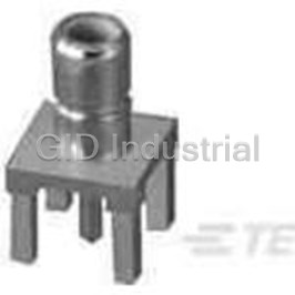
TE CONNECTIVITY 601075

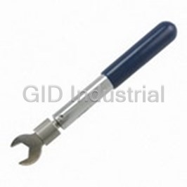
Description
Rota-Crimp Hand Tools
601075
Part Number
601075
Price
Request Quote
Manufacturer
TE CONNECTIVITY
Lead Time
Request Quote
Category
Fasteners, Hardware and Fluid Transfer » Hardware Tools
Specifications
Manufacturer
TE Connectivity
Manufacturers Part #
601075
Industry Aliases
601075
Sub-Category
Hardware Tools
Brand
AMP
Factory Pack Quantity
1
Datasheet
DDEController?Action=showdoc&DocId=Specification+Or+Standard%7F408-2029%7FC%7Fpdf%7FEnglish%7FENG_SS_408-2029_C.pdf
316 KiB

Extracted Text
Instruction Sheet ROTA-CRIMP*HandCrimpingTools 408--2029 601075and601075-1 21APR 11 RevD PROPERUSEGUIDELINES CumulativeTraumaDisorderscanresultfromtheprolongeduseofmanuallypoweredhandtools.Handtoolsareintendedforoccasionaluseandlowvolume applications.Awide selection ofpowered application equipmentforextended--use,production operationsisavailable. 1. INTRODUCTION 3. CRIMPINGPROCEDUREFOR SOLISTRANDTERMINALS ANDSPLICES This instruction sheet covers TE Connectivity Hand 3.1. DieSetting (Figure1) Crimping Tools 601075 and 601075--1, which are used to apply SOLISTRAND* and CABLE MAKER* 1. Open the tool handles. terminals to stranded copper wire. Figure 2 provides 2. Check the die order chart on the tool and select a list of applicable wire sizes, terminal or splice CMA the left (L) and right (R) die numbers for the wire range, and the appropriate minimum and maximum size being used. wire strip lengths for each wire size and connector type. Embossed Numbers Must Match Do NOT use these tools on aircraft applications NOTE or on aluminum wire terminations. Locator Locator Pin Pin i Reasons for reissue are provided in Section 9, REVISION SUMMARY. Indexing Pins 2. DESCRIPTION The hand crimping tools feature two rotating crimping dies that are held in place by spring--loaded indexing pins. Each die is positioned using a spring--loaded die locator pin. Wire size designations are embossed on the crimping dies to assure proper setting of the crimping area, and a die order chart is included on the Figure 1 tool for easy reference. SOLISTRAND TERMINALSAND SPLICES RingType Butt Splice ParallelSplice Terminal WIRESTRIPLENGTH BUTT PARALLEL TERMINALOR SPLICE APPROX TERMINALS SPLICES SPLICES W WIIR RE ES SIIZ ZE ER RANGE ANGE,, WIR WIRE ES SIZE IZE,, 2 mm [CMA] AWG MIN MAX MIN MAX MIN MAX 6.6 -- 10.5[13,100 -- 20,800] 8 8.33[.328] 9.12[.359] 10.32 [.406] 11.11[.438] 10.32[.406] 11.11[.438] 10.5 -- 16.7 [20,800 -- 33, 100] 6 9.92[.391] 10.71 [.422] 11.90[.469] 12.70[.50] 11.11[.438] 11.90[.469] 16.7 -- 26.6[33,100 -- 52,600] 4 11.50[.453] 12.30[.484] 13.49[.531] 14.28[.562] 13.49[.531] 14.28[.562] 26.6 -- 42.4[52,600 -- 83,700] 2 13.09[.515] 13.89[.547] 15.08[.594] 15.87[.625] 15.08[.594] 15.87[.625] 42.4 -- 60.5[83,700 -- 119,500] 1/0 18.65[.734] 20.24[.797] 15.87[.625] 17.46[.688] 17.46[.688] 19.05[.75] Figure 2 E2011 Tyco Electronics Corporation, a TE Connectivity Ltd. Company TOOLING ASSISTANCE CENTER 1--800--722--1111 This controlled document is subject to change. 1 of 10 All Rights Reserved PRODUCT INFORMATION 1--800--522--6752 For latest revision and Regional Customer Service, *Trademark visit our website at www.te.com LOCB TE Connectivity, TE connectivity (logo), and TE (logo) are trademarks. Other logos, product and/or Company names may be trademarks of their respective owners. ORIGINAL INSTRUCTIONS 408-2029 3. Depress the spring--loaded indexing pins and 3.4. PerformingaDualCrimponSOLISTRAND rotate the desired size dies into crimping position. TerminalswithWireSize2and1/0 (Figure4) The embossed die numbers must match. For best results, position the brazed seam of the NOTE terminal against one of the “flats” of the dies, as 4. When the correct size dies are in position, shown in Figure 4. Make sure that the crimps do release the indexing pins. Make sure that the die i not overlap or go off either end of the wire barrel. locator pins return fully and are visible at the points Make sure that the wire size being used, the wire indicated. size stamped on the terminal, and the wire size embossed on the dies all correspond. Always store the tool with the crimping dies in the NOTE No. 4 setting. A. FirstCrimp i 1. Position the end of the terminal or splice wire barrel in the dies as shown in Figure 4. 3.2. WirePreparationandLoading (Figure2) 2. Close the tool handles until the terminal or splice is held in place. Do not deform the wire barrel. 1. Strip the wire(s) to the dimensions indicated. Do 3. Insert the stripped wire into the terminal or NOT use wires with nicked or missing strands. splice’s wire barrel until the end of the conductor is flush with, or is extended slightly beyond, the wire 2. Select the proper size terminal or splice for the barrel. wire size being used. 4. Complete the crimp by closing the tool handles 3. Determine the correct terminal or splice wire until they bottom. loading by referring to the CMA range listed. The B. SecondCrimp total CMA of the wires being used must be within the terminal or splice’s CMA range. 1. Move the terminal or splice into position for the second crimp, then close the tool handles to complete the crimp. Do not overlap the crimps. 3.3. PerformingaSingleCrimponWireSizes8 Through4 (Figure3) 2. Refer to Section 5 and to Figure 7 for terminal and splice crimp inspection procedures. Make sure that the wire size stamped on the NOTE 3.5. PerformingaDualCrimponSOLISTRANDButt terminal or splice corresponds with the wire size SpliceswithWireSize2and1/0 (Figure 4) embossed in the tool dies. i For best results, position the brazed seam of the NOTE terminal against one of the “flats” of the dies, as 1. Center the wire barrel of the terminal or splice in shown in Figure 4. Make sure that the crimps do i the dies. For best results, position the brazed not overlap or go off either end of the wire barrel. seam against one of the “flats” of the dies, as Make sure that the wire size being used, the wire shown in Figure 3. size stamped on the terminal, and the wire size embossed on the dies all correspond. 2. Close the tool handles until the terminal or splice is held firmly in place. Do NOT deform the terminal A. FirstandSecondCrimps or splice wire barrel. 1. Position the end of the splice wire barrel in the dies. 3. Insert the stripped wire into the terminal or splice until the wire conductor is at least flush with, 2. Close the tool handles until the splice is held in or is extending beyond, the end of the wire barrel. place. Do not deform the wire barrel. 3. Insert a properly stripped wire into the first end of the splice until the wire bottoms against the 4. To complete the crimp, close the tool handles splice wire stop. until they bottom. Open the handles and remove the crimped terminal or splice. 4. Close the tool handles until they bottom to complete the crimp. 5. If terminating a butt splice, repeat the procedure 5. Move the splice into position for the second for the second splice end. crimp, as shown in Figure 4. 6. Refer to Section 5 and Figure 7 for terminal and 6. Close the tool handles to complete the crimp. splice crimp inspection procedure. Do not overlap the crimps. 2 of 10 Rev D 408-2029 A B C Terminals ButtSplices Parallel Splices Conductor is Flush with Brazed Seam or Extended Slightly Beyond End of Against Flat Wire Barrel of Die Brazed Seam Brazed Seam Against Flat Against Flat Conductor Splice of Die of Die Butted Against Centered in Wire Stop Dies Wire Barrels Conductors are Flush with Centered in Dies or Extended Slightly Beyond Endof WireBarrel Figure 3 Conductor is Flush with or Extended Slightly Beyond End of Wire Barrel A Terminals 1st Crimp Brazed Seam 2nd Crimp (a) Against Flat (b) of Die Conductor Butted Against Wire Stop Brazed Seam 1st Crimp 2nd Crimp AgainstFlatofDie (a) (b) Conductor Butted Against B Wire Stop ButtSplices 3rd Crimp 4th Crimp (c) (d) Conductor is Flush with or Extended C Slightly Beyond Parallel Splices Endof WireBarrel Brazed Seam AgainstFlatofDie 2nd Crimp 1st Crimp (b) (a) Figure 4 Rev D 3 of 10 408-2029 B. ThirdandFourthCrimps (Figure4) 4. CRIMPINGPROCEDUREFORCABLEMAKER BATTERYTERMINALS 1. Position the splice into position for the third crimp. 4.1. DieSetting 2. Close the tool handles until the splice is held in Proper die setting is determined by the part number of place. Do not deform the wire barrel. the terminal being crimped and by the number displayed in “area 2” of the terminal, as shown in 3. Insert a properly stripped wire into the second Figure 5. end of the splice until the wire bottoms against the 1. Open the tool handles. splice wire stop. 2. Depress the spring--loaded index pins. 4. Close the tool handles until they bottom to complete the crimp. 3. Rotate the dies until the embossed wire size numbers in each die crimp closure match the 5. Move the splice into position for the fourth number displayed in “area 2” of the terminal. crimp. 4. Release the indexing pins, making sure that the 6. Close the tool handles to complete the crimp. die locator pins return fully and are visible at the Do not overlap the crimps. points indicated in Figure 1. 7. Refer to Section 5 and Figure 7 for terminal and splice crimp inspection procedure. 4.2. WirePreparationandLoading 1. Strip the wires to the dimensions indicated in Figure 5. 3.6. PerformingaDualCrimponSOLISTRAND ParallelSpliceswithWireSize2and1/0 (Figure4) Do not use wires with nicked or missing strands. NOTE For best results, position the brazed seam of the NOTE i terminal against one of the “flats” of the dies, as shown in Figure 4. Make sure that the crimps do i not overlap or go off either end of the wire barrel. 2. Select the proper terminal number for the wire Make sure that the wire size being used, the wire diameter being used. The diameter of the stripped size stamped on the terminal, and the wire size wire must fall within the wire diameter range of the embossed on the dies all correspond. terminal being used. Refer to Figure 5. A. FirstCrimp 4.3. CrimpingProcedureforStraightTerminals (Figure6) 1. Position the end of the splice wire barrel in the dies. A. FirstCrimp 2. Close the tool handles until the splice is held in 1. Position the end of the terminal wire barrel in the place. Do not deform the wire barrel. dies. 3. Insert the properly stripped wire into the wire 2. Close the tool handles until the terminal is held barrel until the ends of the conductors are flush in place. Do not deform the wire barrel. with or extended slightly beyond the end of the 3. Insert the properly stripped wire into the wire wire barrel. barrel until the wire bottoms. 4. Close the tool handles until they bottom to 4. Close the tool handles until the dies bottom to complete the crimp. complete the crimp. B. SecondCrimp B. SecondCrimp 1. Move the splice into position for the second 1. Move the terminal into position for the second crimp and close the tool handles to complete the crimp, then close the handles to complete the crimp. Do not overlap the crimps. crimp. 2. Refer to Section 5 and Figure 7 for terminal and 2. Refer to Section 5 and Figure 8 for terminal splice crimp inspection procedure. crimp inspection procedure. 4 of 10 Rev D 408-2029 CABLE MAKER Battery Terminals Area 1 (Die Setting for Tool Area 1 (Die Setting for Tool Nos. 600850, 600850--1 and 69015) Nos. 600850, 600850--1 and 69015 Area 2 (Die Setting for Tool Nos. 601075, 601075--1, and Straight 69015 Flag Area 2 (Die Setting for Tool B Nos. 601075, 601075--1, and 69015) WIRESTRIPLENGTH TERMINAL TOOLDIE WIRE PART SETTINGS(See DIAMETER STRAIGHT FLAG NUMBER Area2onTerminal) RANGE MIN MAX 5.56 -- 6.91 4 29251 [.219 -- .272] 4.75 -- 5.54 6 29253 [.187 -- .218] 20.637 21.432 “B” Dim 29245--3 9.78 -- 10.97 [.813] [.843] +.795[.031] 0 29245--5 [.385 -- .432] 29249 6.93 -- 8.76 29249--3 2 [.273 -- .345] 29249--5 Figure 5 4.4. CrimpingProcedureforFlagTerminals (Figure6) 5. CRIMPINSPECTION Inspect the crimped SOLISTRAND terminal or splice Make sure that crimps do not overlap or go off NOTE by checking the features described in Figure 7. the end of the wire barrel. Inspect the crimped CABLE MAKER terminal by i checking the features described in Figure 8. Use only terminals and splices that meet the conditions A. FirstCrimp (Figure6) described. 1. Orient and position the flag terminal in the tool dies. 6. INITIALTOOLINSPECTION 2. Close the tool handles until the terminal is held AMP Hand Crimping Tools 601075 and 601075--1 are in place. Do not deform the wire barrel. inspected before shipment. The tool received should be inspected immediately upon arrival to ensure that 3. Insert the properly stripped wire until the end of it has not been damaged during shipment, and that it the conductor is flush with, or extends performs according to the criteria described in this approximately .79 [.031] in. beyond, the end of the sheet. If the tool is damaged upon arrival, retain the terminal wire barrel. shipping container, file a claim with the carrier, and notify TE immediately. 4. Close the tool handles to complete the crimp. 7. MAINTENANCE/INSPECTION B. SecondCrimp (Figure6) 1. Move the terminal into position for the second 7.1. DailyMaintenance crimp. Close the tool handles to complete the 1. Remove dust, moisture, and other contaminants crimp. from the tool with a clean brush or a soft, lint--free 2. Refer to Section 5 and Figure 8 for battery cloth. Do NOT use objects that could damage the terminal crimp inspection procedure. tool. Rev D 5 of 10 408-2029 Straight Flag AB C D Terminals Terminals End of Conductor Flush or Extended Approximately .79 [.031] Beyond Terminal Wire Barrel 1st 1st 2nd 2nd Crimp Crimp Crimp Crimp Do Not Overlap First Crimp Figure 6 2. Make certain that all pins, pivot points, and 2. Make certain that all parts are securely in place. bearing surfaces are protected with a THIN coat of If replacements are necessary, refer to the parts any good SAE 20 motor oil. Do NOT oil list in Figure 11. excessively. 3. Inspect crimping areas for chipped or cracked 3. When the tool is not in use, keep the handles surfaces. closed to prevent objects from becoming lodged in the crimping areas and store the tool in a clean, B. HandleAdjustmentInspection (Figure9) dry area. The handle adjustment should be checked to ensure 7.2. PeriodicInspection that the dies are bottoming fully. The handle Regular inspections should be performed by quality adjustment feature is provided to compensate for control personnel. A record of scheduled inspections normal die wear. To check the handle adjustment: should remain with the tool and/or be supplied to 1. Open the tool handles fully. supervisory personnel responsible for the tool. Though recommendations call for at least one 2. Rotate the No. 4 wire size dies into crimping inspection per month, the inspection frequency should position. be based on the amount of use, working conditions, operator training and skill, and established company 3. Close the tool handles until the dies are standards. These inspections should be performed in bottomed, but not under pressure. the following sequence: 4. Measure the distance between the tool handles, A. VisualInspection as shown in Figure 9. The measurement must be 1. Remove all lubrication and accumulated film by between 28.58 [1.125] and 38.10 [1.500]. If the immersing the tool (handles partially closed) in a adjustment does not fall within this range, the suitable commercial degreaser that will not affect adjustment must be tightened or loosened as paint or plastic material. necessary. 6 of 10 Rev D 408-2029 Single Crimp Dual Crimp SOLISTRAND Terminals SOLISTRAND Terminals and Splices and Splices 3 3 1 Terminal 1 5 Terminal 5 Wire Size 2 Stamped Under 2 Tongue 1 Wire Size Stamped Under 1 Tongue 5 3 Parallel Splice 2 3 5 Wire Size Stamped Parallel on Splice Splice 3 1 1 Wire Size 5 Wire Size Stamped 2 2 Stamped 4 on Splices on Splice 4 ButtSplice 3 ButtSplice 1 1 3 1 1 Crimpcentered. Crimpmaybeoff center BUT NOT CrimpsevenlyspacedBUT NOT OVERLAPPED OR OFF END OF WIRE BARREL. OFF END OF WIRE BARREL. 2 2 Wiresizestampedonterminalor splicematches Wiresizestampedonterminalor splicematches CMA of wirebeingused. CMA of wirebeingused. 3 3 Insulationdoesnot enter wirebarrel. Insulationdoesnot enter wirebarrel. 4 4 Wireisvisiblethroughinspectionholeof butt splice. Wireisvisiblethroughinspectionholeof butt splice. 5 5 Onterminalsandparallelsplices, barewireends Onterminalsandparallelsplices, barewireends must beflushwithor extendslightlybeyondendof wire must be flush with or extend slightlybeyondend barrel. of wirebarrel. Figure 7 Rev D 7 of 10 408-2029 CABLE MAKER Battery Terminals StraightTerminal Flag Terminal 2 3 2 3 1 1 Area 2 4 5 4 Area 2 5 StraightTerminal Flag Terminal 1 1 CrimpsevenlyspacedBUT NOT OVERLAPPED OR Crimpsproperlylocated. Crimpsmust not beoff endof wire OFF END OF WIRE BARREL. barrel. 2 2 Diameter of strippedwireiswithinwirediameter Diameter of strippedwireiswithinwirediameter rangeof terminal. rangeof terminal. 3 3 Nonickedor missingconductor strands. Nonickedor missingconductor strands. 4 4 Wirefullyinserted. Endof conductor isflushor extendedapproximately 0.79[.031] beyondendof terminalwirebarrel. 5 5 Selecteddienumbersmatchthenumber displayedin Selecteddienumbersmatchthenumber displayedin Area2. Area2. Figure 8 5. To loosen the adjustment: No. 4 Dies in a. --Turn both adjustment (ADJ) screws Crimp Position COUNTERCLOCKWISE approximately 1/8 to 1/4 turn. b. --Slightly loosen both lock (LOCK) screws by turning them COUNTERCLOCKWISE. Dies Bottomed But Not Under c. --Flex the tool by opening and closing the tool Pressure handles. Adjustment Screws d. --Tighten both lock screws. e. --Close the tool handles until the dies are Lock bottomed, but not under pressure. Check the Screws measurement between the tool handles and repeat the adjustment procedure if necessary. 6. To tighten the adjustment: a. --Turn both lock (LOCK) screws COUNTERCLOCKWISE approximately 1/2 to 3/4 turn. --Turn both adjustment (ADJ) screws 28.58 [1.125] CLOCKWISE approximately 1/8 to 1/4 turn. to b. --Flex the tool by opening and closing the tool 38.10 [1.500] handles. c. --Tighten both lock (LOCK) screws. d. ---Close the tool handles until the dies are bottomed but not under pressure. Check the measurement between the tool handles and Figure 9 repeat the adjustment procedure if necessary. 8 of 10 Rev D 408-2029 C. CrimpHeightInspection (Figure10) 9. REVISIONSUMMARY S Updated document to corporate requirements Crimp height inspections should be performed periodically to determine if the tool is maintaining S New logo proper crimping dimensions. To check the crimp height: 1. Perform the handle adjustment inspection as described in Paragraph B, Handle Adjustment CrimpHeightMeasurements Inspection. Adjust the handles if necessary. (Tool Handles Properly Adjusted. See paragraph 7.2, B) 2. Crimp a properly prepared stranded wire in a SOLISTRAND terminal or splice, as previously “A” described. Do not use wires with missing conductor strands. NOTE i “B” 3. Using a conventional cone--point micrometer, measure the crimp heights at the midpoints of flats Avoid “A” and “B”, as shown in Figure 10. The SUM of Brazed the two measurements equals the crimp height Seam dimension. Measure at Midpoints Do not allow the cone point to enter the terminal NOTE of Flats brazed seam. i “A” Cross Section “A” + “B” = Crimp of Crimped Wire 4. Figure 10 lists the crimp height dimension (sum Height Dimension Barrel of “A” and “B” measurements) range for each wire size. If the measured dimension is within the listed “B” range, the die closure is considered dimensionally correct. 5. If the measured crimp height dimension is not within the specified range (and the tool handles are properly adjusted), crimping tool should be returned to TE for reconditioning. Refer to Section WIRE CRIMPHEIGHT CRIMPHEIGHT SIZE, DIMENSION 8, REPAIR/REPLACEMENT. MEASUREMENTH AWG RANGE 10.46--11.05 8 [.412--.435] 8. REPAIR/REPLACEMENT 13.00--13.59 6 Replaceable parts are listed in Figure 11. Parts other MEASUREMENTS [.512--.535] than those listed in Figure 11 should be replaced by 16.23--16.92 “A” + “B” = TE to ensure quality and reliability of the tool. Order 4 [.639--.666] CRIMP HEIGHT replacement parts through your TE representative, or DIMENSION 19.41--20.14 call 1--800--526--5142, or send a facsimile of your 2 [.764--.793] purchase order to 1--717--986--7605, or write to: 22.63--23.42 1/0 [.891--.922] CUSTOMER SERVICE (38--35) TYCO ELECTRONICS CORPORATION H Tool handlesproperlyadjusted. P.O. BOX 3608 Figure 10 HARRISBURG, PA 17105--3608 For tool repair service, please contact a TE Representative at 1--800--526--5136. Rev D 9 of 10 408-2029 13 11 12 117.6 mm [4.63 in.] 381 mm [15.0 in.] 11 12 NOTE: CERTI--CRIMP* Hand Tool Ratchet Assembly No. 604220--1 1 (Items 1 Thru 10) is Used on Tool No. 601075--1 Only. 4 5 3 8 6 QTYPER ITEM PARTNO. DESCRIPTION 5 TOOL 1 1--21004--2 2 SCREW, Shoulder 5/16in. Dia. 9 2 604222--1 1 GUARD 1 3 604224--1 1 BUSHING 4 604223--1 1 PAWL 5 21021--5 2 NUT ,1/4in. 6 986816--2 1 SPRING 7 7 604228--1 1 RACK 8 21021--6 1 NUT, 5/16in. 9 604229--1 1 WASHER, Nylon 10 2--21004--1 1 SCREW, Shoulder 3/8in. Dia. 2 11 601092 2 DIES 12 601077 2 PIN ASSEMBLY, Index 10 13 604274--1 2 HANDLE, Grips, Figure 11 10 of 10 Rev D
Frequently asked questions
How does Electronics Finder differ from its competitors?

Is there a warranty for the 601075?
Which carrier will Electronics Finder use to ship my parts?
Can I buy parts from Electronics Finder if I am outside the USA?
Which payment methods does Electronics Finder accept?
Why buy from GID?

Quality
We are industry veterans who take pride in our work

Protection
Avoid the dangers of risky trading in the gray market

Access
Our network of suppliers is ready and at your disposal

Savings
Maintain legacy systems to prevent costly downtime

Speed
Time is of the essence, and we are respectful of yours
Related Products
Crimpers TOOL 1055236-1
Mini Torque Wrenches 1055258-1

Wrenches 2098 0351 54 1055276-1
Hand Tools CABLE BENDER 1055479-1
Connector Accessories Crimp Assembly Kit 1055779-1
Crimpers TOOL 1055835-1
Request a Quote

The quote request has been received
Close

Facing challenges or have inquiries? Feel free to contact us!
Call Us +1-469-283-2440
What they say about us
FANTASTIC RESOURCE
One of our top priorities is maintaining our business with precision, and we are constantly looking for affiliates that can help us achieve our goal. With the aid of GID Industrial, our obsolete product management has never been more efficient. They have been a great resource to our company, and have quickly become a go-to supplier on our list!
Bucher Emhart Glass
EXCELLENT SERVICE
With our strict fundamentals and high expectations, we were surprised when we came across GID Industrial and their competitive pricing. When we approached them with our issue, they were incredibly confident in being able to provide us with a seamless solution at the best price for us. GID Industrial quickly understood our needs and provided us with excellent service, as well as fully tested product to ensure what we received would be the right fit for our company.
Fuji
HARD TO FIND A BETTER PROVIDER
Our company provides services to aid in the manufacture of technological products, such as semiconductors and flat panel displays, and often searching for distributors of obsolete product we require can waste time and money. Finding GID Industrial proved to be a great asset to our company, with cost effective solutions and superior knowledge on all of their materials, it’d be hard to find a better provider of obsolete or hard to find products.
Applied Materials
CONSISTENTLY DELIVERS QUALITY SOLUTIONS
Over the years, the equipment used in our company becomes discontinued, but they’re still of great use to us and our customers. Once these products are no longer available through the manufacturer, finding a reliable, quick supplier is a necessity, and luckily for us, GID Industrial has provided the most trustworthy, quality solutions to our obsolete component needs.
Nidec Vamco
TERRIFIC RESOURCE
This company has been a terrific help to us (I work for Trican Well Service) in sourcing the Micron Ram Memory we needed for our Siemens computers. Great service! And great pricing! I know when the product is shipping and when it will arrive, all the way through the ordering process.
Trican Well Service
GO TO SOURCE
When I can't find an obsolete part, I first call GID and they'll come up with my parts every time. Great customer service and follow up as well. Scott emails me from time to time to touch base and see if we're having trouble finding something.....which is often with our 25 yr old equipment.
ConAgra Foods