

 Manufacturers
TE CONNECTIVITY 696125-1

Description
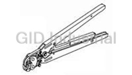
"Assembly Tools, Super Champ IV Hand Tool 696125 1"
696125-1
Part Number
696125-1
Price
Request Quote
Manufacturer
TE CONNECTIVITY
Lead Time
Request Quote
Category
Tools and Supplies » Assembly Tools
Specifications
Manufacturer
TE Connectivity
Manufacturers Part #
696125-1
Industry Aliases
696125-1
Sub-Category
Electronics Assembly Tools
Brand
AMP
Factory Pack Quantity
1
Datasheet
DDEController?Action=showdoc&DocId=Specification+Or+Standard%7F408-8617%7FA%7Fpdf%7FEnglish%7FENG_SS_408-8617_A.pdf
271 KiB

Extracted Text
Instruction Sheet SUPER CHAMP* IV Hand Tool 408-8617 696125-1 22 JUN 10 Rev A PROPER USE GUIDELINES Cumulative Trauma Disorders can result from the prolonged use of manually powered hand tools. Hand tools are intended for occasional use and low volume applications. A wide selection of powered application equipment for extended-use, production operations is available. Front of Tool Wire Cutter Handles Stud Size Wire Stripper Bolt Cutter Red (22-16) Gage Blue (16-14) Color Dots Jaws Insulated Terminal Yellow and Splice Uninsulated Terminal Ignition Terminal (12-10) Crimping Chambers and Splice Crimping Chamber Color Dot Crimping Chambers Figure 1 1. INTRODUCTION 3.2. Stripping the Wire SUPER CHAMP IV Hand Tool 696125-1 is used to cut 1. Using the strip length gage (on back of hand and strip wire, crimp sizes 22-16, 16-14, and 12-10 tool), determine the strip length of the wire. terminals and splices to wires, and crimp 7-mm 2. Place the wire in the applicable position of the ignition terminals. The tool is also capable of cutting wire stripper, then close the handles, rotate the bolts and gaging various stud sizes. tool, and pull the wire from the tool. Dimensions in this instruction sheet are in NOTE 3.3. Crimping Terminals millimeters [with inches in brackets]. Figures are not drawn to scale. For crimp inspection requirements, refer to the i NOTE applicable Application Specification (114-series). Reasons for reissue of this instruction sheet are i provided in Section 6, REVISION SUMMARY. A. Insulated Terminals 2. DESCRIPTION 1. Insert the terminal into the RED (22-16) or BLUE (16-14) dot color-coded crimping chamber The hand tool consists of two jaws and handles. The jaws feature crimping chambers, a wire cutter, so that the tongue end of the insulation barrel is 0.76 [.03] from the edge of the jaws, or bolt cutter, stud size gage, wire stripper, and strip insert the terminal into the YELLOW (12-10) dot length gage. The crimping chambers are marked with the wire size range; and in addition, the crimping color-coded crimping chamber so that the tongue end of the insulation barrel is 1.59 [.06] from the chambers for insulated terminals and splices are edge of the jaws. Refer to Figure 2. color-coded. The crimping chamber for ignition terminals is marked “7 MM”. See Figure 1. For PLASTI-GRIP* ribbed terminals, align the jaws between the ribs. The stud size gage can be used to assist in selecting the correct terminal stud size. 2. Close the tool handles completely. 3. For terminals in the RED or BLUE dot 3. OPERATION color-coded crimping chamber, re-position the 3.1. Cutting the Wire terminal so that the wire end of the wire barrel is 0.76 [.03] from the edge of the jaws. Place the wire between the cutting surfaces of the wire cutter, and close the handles. ©2010 Tyco Electronics Corporation, Berwyn, PA This controlled document is subject to change. TOOLING ASSISTANCE CENTER 1-800-722-1111 1 of 2 All Rights Reserved For latest revision and Regional Customer Service, PRODUCT INFORMATION 1-800-522-6752 TE logo and Tyco Electronics are trademarks. visit our website at www.tycoelectronics.com *Trademark. Other products, logos, and company names might be trademarks of their respective owners. LOC B 408-8617 For terminals in the YELLOW (12-10) dot Crimping Terminals color-coded crimping chamber, re-position the Wire Barrel terminal so that the wire end of the wire barrel is 1.59 [.06] from the edge of the jaws. 4. Close the tool handles completely. Insulation Tongue Barrel B. Uninsulated Terminals Crimping Splices 1. Insert the terminal in the crimping chamber marked "NON INS". Center the wire barrel in the Insulation crimping chamber. Refer to Figure 2. Wire Barrel Barrel 2. Close the tool handles completely. Wire Barrel Insulation C. Ignition Terminals Barrel 1. Insert the terminal in the crimping chamber marked “7 MM”. See Figure 1. Center the wire Figure 2 barrel in the crimping chamber. 2. Close the tool handles completely. 3.6. Using the Stud Size Gage Lay the terminal stud hole over a stud size circle 3.4. Crimping Splices marking on the jaw of the hand tool. The circles A. Insulated Splices represent the actual diameter of the stud. The correct stud size circle will be visible through the terminal 1. Insert the splice into the RED (22-16), BLUE stud hole. (16-14), or YELLOW (12-10) dot color-coded crimping chamber so that the center of the 4. MAINTENANCE AND INSPECTION insulation barrel is 3.18 [.13] from the edge of the jaws. Refer to Figure 2. It is recommended that a maintenance and inspection program be performed periodically to ensure 2. Close the tool handles completely. dependable and uniform terminations. Frequency of 3. For splices in the RED or BLUE dot inspection depends on: color-coded crimping chamber, re-position the — type and size of the product crimped splice so that the wire end of the wire barrel is 0.76 [.03] from the edge of the jaws. — degree of operator skill — presence of abnormal amounts of dust and dirt For splices in the YELLOW dot color-coded — your own established standards crimping chamber, re-position the splice so that wire end of the wire barrel is 1.59 [.06] from the The hand tool is thoroughly inspected before edge of the jaws. packaging. Since there is a possibility of damage during shipment, the hand tool should be inspected 4. Close the tool handles completely. immediately upon arrival at your facility. B. Uninsulated Splices 5. REPLACEMENT AND REPAIR 1. Insert the splice in the crimping chamber marked "NON INS". Center the wire barrel in the This tool is not repairable. Order replacement tools crimping chamber. Refer to Figure 2. through your representative, or call 1-800-526-5142, or send a facsimile of your purchase order to 2. Close the tool handles completely. 717-986-7605, or write to: 3.5. Cutting Bolts CUSTOMER SERVICE (038-035) TYCO ELECTRONICS CORPORATION 1. Open the tool handles. PO BOX 3608 2. Thread the bolt into the appropriate-sized HARRISBURG PA 17105-3608 opening on the side of the tool marked, "INSERT SCREW HERE". See Figure 1. 6. REVISION SUMMARY Allow 3.05 [.12] for tool thickness. Revisions to this instruction sheet include: NOTE • Updated instruction sheet to corporate i requirements • Modified Figure 1, and Paragraphs 3.3, 3.4, 3. Close the tool handles until the bolt is cut. and 3.5 • Added Figure 2, and Paragraphs 3.4,C and 3.6 2 of 2 Rev A
Frequently asked questions
How does Electronics Finder differ from its competitors?

Is there a warranty for the 696125-1?
Which carrier will Electronics Finder use to ship my parts?
Can I buy parts from Electronics Finder if I am outside the USA?
Which payment methods does Electronics Finder accept?
Why buy from GID?

Quality
We are industry veterans who take pride in our work

Protection
Avoid the dangers of risky trading in the gray market

Access
Our network of suppliers is ready and at your disposal

Savings
Maintain legacy systems to prevent costly downtime

Speed
Time is of the essence, and we are respectful of yours
Related Products

Torque Wrenches Are Used To Properly Install Or Disassemble The Connectors 1055419-1
Tool For RF Connectors 1055442-1
Tool For RF Connectors 1055443-1
Insertion Tool For RF Connectors 1055447-1
Insertion Tool For RF Connectors 1055448-1
Assembly Tools, Sma Right Angle Cable Plugs 1055451-1
Request a Quote

The quote request has been received
Close

Facing challenges or have inquiries? Feel free to contact us!
Call Us +1-469-283-2440
What they say about us
FANTASTIC RESOURCE
One of our top priorities is maintaining our business with precision, and we are constantly looking for affiliates that can help us achieve our goal. With the aid of GID Industrial, our obsolete product management has never been more efficient. They have been a great resource to our company, and have quickly become a go-to supplier on our list!
Bucher Emhart Glass
EXCELLENT SERVICE
With our strict fundamentals and high expectations, we were surprised when we came across GID Industrial and their competitive pricing. When we approached them with our issue, they were incredibly confident in being able to provide us with a seamless solution at the best price for us. GID Industrial quickly understood our needs and provided us with excellent service, as well as fully tested product to ensure what we received would be the right fit for our company.
Fuji
HARD TO FIND A BETTER PROVIDER
Our company provides services to aid in the manufacture of technological products, such as semiconductors and flat panel displays, and often searching for distributors of obsolete product we require can waste time and money. Finding GID Industrial proved to be a great asset to our company, with cost effective solutions and superior knowledge on all of their materials, it’d be hard to find a better provider of obsolete or hard to find products.
Applied Materials
CONSISTENTLY DELIVERS QUALITY SOLUTIONS
Over the years, the equipment used in our company becomes discontinued, but they’re still of great use to us and our customers. Once these products are no longer available through the manufacturer, finding a reliable, quick supplier is a necessity, and luckily for us, GID Industrial has provided the most trustworthy, quality solutions to our obsolete component needs.
Nidec Vamco
TERRIFIC RESOURCE
This company has been a terrific help to us (I work for Trican Well Service) in sourcing the Micron Ram Memory we needed for our Siemens computers. Great service! And great pricing! I know when the product is shipping and when it will arrive, all the way through the ordering process.
Trican Well Service
GO TO SOURCE
When I can't find an obsolete part, I first call GID and they'll come up with my parts every time. Great customer service and follow up as well. Scott emails me from time to time to touch base and see if we're having trouble finding something.....which is often with our 25 yr old equipment.
ConAgra Foods