


 Manufacturers
TE CONNECTIVITY 7-1617758-5

Description
Electromechanical Relay 28VDC 500Ohm 5A DPDT(32.57x10.4x16.26)mm Flange Military Relay
7-1617758-5
Part Number
7-1617758-5
Price
Request Quote
Manufacturer
TE CONNECTIVITY
Lead Time
Request Quote
Category
Relays and I/O Modules » Relay Other
Specifications
Manufacturer
TE Connectivity
Manufacturers Part #
7-1617758-5
Industry Aliases
FCB-205-BY4
Sub-Category
Other Relays
Brand
Raychem Wire and Tubing
Factory Pack Quantity
1
Datasheet

DDEController?Action=srchrtrv&DocNm=5-1773450-5_Section5&DocType=CS&DocLang=EN.pdf
6314 KiB

Extracted Text
CII Mid-Range Relays CII Mid-Range Relays Table of Contents TD2 Series Time Delay Relays, per MIL-PRF-83726/28, /29, /30, & /31 . . . . . . . . . .5-2 – 5-5 Double-pole, Electrically Held, 5 Amps and Less FCB-205 Series . . . . . . . . . . . . . . . . . . . . . . . . . . . . . . . . . . . . . . . . . . . . . . . . .5-6 – 5-8 Four-pole, Electrically Held, 5 Amps and Less FCB-405 Series . . . . . . . . . . . . . . . . . . . . . . . . . . . . . . . . . . . . . . . . . . . . . . . .5-9 – 5-11 Double-pole, Electrically Held, 15 Amps and Less FCA-210 Series . . . . . . . . . . . . . . . . . . . . . . . . . . . . . . . . . . . . . . . . . . . . . . .5-12 – 5-14 FCA-212 Series . . . . . . . . . . . . . . . . . . . . . . . . . . . . . . . . . . . . . . . . . . . . . . .5-15 – 5-17 FCA-215 Series . . . . . . . . . . . . . . . . . . . . . . . . . . . . . . . . . . . . . . . . . . . . . . .5-12 – 5-14 Four-pole, Electrically Held, 15 Amps and Less FCA-410 Series . . . . . . . . . . . . . . . . . . . . . . . . . . . . . . . . . . . . . . . . . . . . . . .5-18 – 5-20 FCA-415 Series . . . . . . . . . . . . . . . . . . . . . . . . . . . . . . . . . . . . . . . . . . . . . . .5-18 – 5-20 Single-pole, Electrically Held, 25 Amps and Less FCA-125 Series . . . . . . . . . . . . . . . . . . . . . . . . . . . . . . . . . . . . . . . . . . . . . . .5-21 – 5-23 Three-pole, Electrically Held, 25 Amps and Less FCA-325 Series . . . . . . . . . . . . . . . . . . . . . . . . . . . . . . . . . . . . . . . . . . . . . . .5-24 – 5-26 Three-pole, Electrically Held, 25 Amps and Less, with Auxiliary Contacts FCAC-325 Series . . . . . . . . . . . . . . . . . . . . . . . . . . . . . . . . . . . . . . . . . . . . . .5-27 – 5-29 Single-Pole, Electrically Held, 50 Amps or Less FCA-150 . . . . . . . . . . . . . . . . . . . . . . . . . . . . . . . . . . . . . . . . . . . . . . . . . . . . .5-30 – 5-33 Single-Pole, Electrically Held, 50 Amps and Less, Normally Closed, with Auxiliary Contacts FCA-150NC . . . . . . . . . . . . . . . . . . . . . . . . . . . . . . . . . . . . . . . . . . . . . . . . . .5-34 – 5-37 Single Pole, Electrically Held, 50 Amps and Less, with Auxiliary Contacts 5 FCAC-150 . . . . . . . . . . . . . . . . . . . . . . . . . . . . . . . . . . . . . . . . . . . . . . . . . . .5-38 – 5-41 Selection and Application Guide . . . . . . . . . . . . . . . . . . . . . . . . . . . . . . . . . . . . . . . . . . . .5-42 Cross Reference - Socket to Relay . . . . . . . . . . . . . . . . . . . . . . . . . . . . . . . . . . . . . . . . . .5-43 5–1 Catalog 5-1773450-5 Dimensions are shown for Dimensions are in millimeters USA: +1 800 522 6752 For additional support numbers Revised 3-13 reference purposes only. unless otherwise specified. Asia Pacific: +86 0 400 820 6015 please visit www.te.com Specifications subject UK: +44 800 267 666 www.te.com to change. CII Mid-Range Relays TD2 Series Time Delay Relay Product Facts n Qualified to: MIL-PRF-83726/28 MIL-PRF-83726/29 MIL-PRF-83726/30 MIL-PRF-83726/31 n Fixed delay on operate, fixed delay on release, adjustable delay on operate & adjustable delay on release TD2 series time delay relays mable digital pulse counter, follows and connecting it n Meets or exceeds are available for delay on gating a semiconductor externally to terminals 1D - electrostatic discharge operate or delay on release switch to operate the relay. 3D as below. operation. Either can be Timing is independent of MIL-STD-1686 Class R = [(T / T ) -1] 100K EXT 1 0 supplied as fixed or resistor whether the controlling Non-Sensitive Ohms adjustable types. Both voltage is a ramp or step n Welded hermetically sealed T = Minimum time of military and commercial function. 0 enclosure occupies about 1 selected decade in versions are offered. 3 3 in (16.4 cm ) seconds. For the adjustable models n 10A, 2 form C (DPDT) output T1 = Required time delay. These products consist of the user specifies a one contacts solid state timing circuits decade range in seconds, EXAMPLE controlling our FCA-210 within which the required Selected Range = 3-30 sec series relays, providing 2 delay will be set. This range Form C (DPDT) output is programmed internally at Required Time = 15 sec contacts rated 10 amps. the time of manufacture. R = [(15/3) -1] 100K = EXT The internal timing circuit The required delay is 400K uses an R/C controlled obtained by calculating the oscillator with a program- oscillator timing resistor as Timing Action and Terminal Wiring Delay On Operate: Delay On Release: The time delay starts on the application of input voltage to X1-X2. The timing The input voltage is continuous to X1-X2. When the control voltage is applied to circuit energizes the end of the time delay period. C1-X2 the timing circuit and the relay are both energized. The time delay starts when the control voltage is shut off. 20-30VDC 20-30VDC INPUT VOLTAGE INPUT VOLTAGE INPUT OFF +X1 / –X2 INPUT OFF +X1 / –X2 20-30VDC ENERGIZED CONTROL VOLTAGE TIME OUTPUT CONTROL OFF +C1 / –X2 DEENERGIZED DELAY RELAY ENERGIZED OUTPUT DEENERGIZED TIME DELAY RELAY (–) (–) Fixed Model Fixed Model 12 -X2 3 1 -X2 2 3 D D TD TD C C CONTROL (+) B B INPUT INPUT A A +X1 +X1 (+) BLUE BEAD (+) BLUE BEAD Adjustable Model EXT. RESISTOR 1/4 WATT MIN. Adjustable Model EXT. RESISTOR 1/4 WATT MIN. (–) (–) 12 -X2 3 12 -X2 3 D D TD TD C C CONTROL (+) B B INPUT INPUT A A +X1 +X1 (+) BLUE BEAD (+) BLUE BEAD Terminal designations shown in the diagrams above are for reference only. They do not appear on the relay header. 5–2 Catalog 5-1773450-5 Dimensions are shown for Dimensions are in millimeters USA: +1 800 522 6752 For additional support numbers Revised 3-13 reference purposes only. unless otherwise specified. Asia Pacific: + 8 6 0 400 820 6015 please visit www.te.com Specifications subject UK: +44 800 267 666 www.te.com to change. CII Mid-Range Relays CII Mid-Range Relays TD2 Series Time Delay Relay (Continued) Specifications Timing Data Timing Action Delay on Operate or Delay on Release Time Delay, Fixed – M83726/28, /29 and Commercial 28C, 29C Select from 0.1 to 600 sec for Commercial Models Select from 0.1 to 500 sec for Mil-Spec Models Time Delay, Adjustable – M83726/30, /31 and Commercial 30C, 31C Select one decade between 0.1 to 1.0 and 60 to 600 seconds Timing Accuracy (note 1) ±10% of Nominal Value Recycle Time (note 2) 50 ms, max., to next cycle. Power Interrupts Accuracy is not affected by power interruptions up to 1 ms spaced at least 10ms apart. Input Data Input Voltage 28 Vdc nominal, range 20 - 32 Vdc Duty Rating Continuous Input Current 110 mAdc Max @ 25°C Control Voltage (applies only to Delay on Release type) 20 - 32 Vdc Control Current 15 mAdc Max (applies only to delay on release types) Input Voltage Polarity Protection The timer will be inoperative during, and undamaged by, reversal of the polarity of the input voltage. Output Data Contact Form 2 Form C (DPDT) Contact Material Silver Cadmium Oxide, Gold plated Contact Rating in Amps (Continuous Duty) Type of Life (Min.) 115 Vac 115/200 Vac – 3 phase Load Cycles 28 Vdc 400Hz 400 Hz. 60 Hz.* 3 Resistive 100 x 10 10 10 10 2.5 3 Inductive 20 x 10 888 2.5 3 Motor 100 x 10 444 2.0 3 Lamp 100 x 10 222 1.0 3 * 60 Hz. loads are rated at 10 x 10 cycles. Overload Current 40 Adc; 60A, 400 Hz. 5 Rupture Current 50 Adc; 80A, 400 Hz. Max. Contact Drop at 10A Initial 0.150V; After Life 0.175V Electrical Data Electrostatic Discharge Withstand Voltage 16,000V Transients (note 3): Positive Transients +80V Self-generated Transients ±50V, Max. Spike Susceptibility ±600V, 10 μs, Max. Insulation Resistance (note 4) 1,000 megohms at 500Vdc, between each pin and case Dielectric Strength (note 4) 1,000Vrms at 60 Hz at sea level, between case and all pins connected together Environmental Data Ambient Temperature Range, Operating -55°C to +125°C Altitude 80,000 feet maximum Shock Resistance 100 G’s, 6 ms. Vibration Resistance, Sinusoidal Z & Y Enclosure: 30 G’s, 33-3000Hz.; X & W Enclosure: 20 G’s, 33-3000Hz. Mechanical Data Approximate Weight 2.5 oz. (71g) Max. NOTES 1. The accuracy requirement applies to any combination of operating temperature and voltage. Add ±10ms for timing less than one second. 2. Recycle time to assure that the next timing cycle will be completed. Units can be recycled during timing and after time-out: Delay on operate models – Power must be OFF the input at least 10 ms. Delay on release models – Power must be ON the control terminal at least 10 ms. 3. Transient specifications are based on a maximum duty cycle of 1/50. 4. All wired terminals must be connected together during this test. Dielectric withstanding voltage and insulation resistance are measured between all mutually insulated wired terminals and between all these terminals and case. 5. Inductive loads must be diode suppressed. 5–3 Catalog 5-1773450-5 Dimensions are shown for Dimensions are in millimeters USA: +1 800 522 6752 For additional support numbers Revised 3-13 reference purposes only. unless otherwise specified. Asia Pacific: +86 0 400 820 6015 please visit www.te.com Specifications subject UK: +44 800 267 666 www.te.com to change. CII Mid-Range Relays TD2 Series Time Delay Relay (Continued) N Outline Dimensions N The standard terminal types and enclosures are illustrated below with dimensions expressed as inches ± 0.010 and (millimeters ±0.25). Terminals All terminals on 0.200 (5.4) centers. " CODE "T" CODE "S" CODE "P" Circuit Board Pins – Tin/Lead Plated Socket Pins – Gold Plated Solder Hooks .050 ± .005 (1.27 ± (3) .270 .270 Silicone (6.86) (6.86) Rubber Gasket D + .002 0.80 DIA .062 Dia. Pin - .001 .300 ± .020 ) 1 (2.03) + .05 (1.57 ) 14 Plcs. (7.26) ± .51 - .02 .062 ±.001 Pin (1.57 ± .02) 14 places -X2 -X2 -X2 + .002 D .062 - .001 Dia. Pin ) 1 + .05 (1.57 ) 14 Plcs. - .02 +X1 +X 1 BLUE BEAD BLUE BEAD BLUE BEAD Enclosures E All Enclosures have cupro-nickel cans bright acid tin/lead plated after assembly to terminal headers. CODE .150 typ. CODE (3.8) "Z" 1.015 "Y" (25.79) 1.015 .625 (25.79) .937 (15.88) 1.015 (23.80) (25.79) .312 1.015 FULL R (7.92) (25.79) 1.015 6 PLCS 1.396 (25.79) (35.46) 1. 446 (36.73) 1.00 (25.4) .040 (1.02) 1.718 Max. .156 (43.64) (3.96) .150 typ. CODE CODE .312 (3.8) (7.92) "X" "W" .375 6-32 UNC-2A 3 Studs * (9.52) (9 3 Stu 1.00 .625 (25.4) (15.88) .937 (23.80) .047 1.00 (1.20) (25.4) 1.015 (25.79) 1.396 FULL R 1.015 (35.46) 6 PLCS 1.446 (25.78) (36.73) .687 (17.44) .343 (8.71) .160 1.051 (4.06) (25.79) 1.051 .687 (25.79) (17.44) .040 1.718 Max. (1.02) (43.64) .160 (4.06) *Metric threads available. To specify use “M” in place of “W” To spec For factory-direct application assistance, phone 419-521-9500 or fax 419-526-2749. 5–4 Catalog 5-1773450-5 Dimensions are shown for Dimensions are in millimeters USA: +1 800 522 6752 For additional support numbers Revised 3-13 reference purposes only. unless otherwise specified. Asia Pacific: +86 0 400 820 6015 please visit www.te.com Specifications subject UK: +44 800 267 666 www.te.com to change. CII Mid-Range Relays CII Mid-Range Relays TD2 Series Time Delay Relay (Continued) Part Numbering System Mil-Spec Types Commercial Types Typical Mil-Spec Part Number TD2 28- 5002 P Typical Commercial Part Number TD2 28C- 1001 PY Series: Series: TD2 = Time delay relay with 2 pole, 10A output TD2 = Time delay relay with 2 pole, 10A output Mil-Spec Model: Commercial Model: 28 = M83726/28 (Fixed, Delay on Operate) 28C = Fixed, Delay on Operate (COTS version of M83726/28) 29 = M83726/29 (Fixed, Delay on Release) 29C = Fixed, Delay on Release (COTS version of M83726/29) 30 = M83726/30 (Adjustable, Delay on Operate) 30C = Adjustable, Delay on Operate (COTS version of M83726/30) 31 = M83726/31 (Adjustable, Delay on Release) 31C = Adjustable, Delay on Release (COTS version of M83726/31) Time Delay Range (Within 0.1 to 500 seconds): Time Delay Range (Within 0.1 to 600 seconds): For /28 and /29 types (fixed types), the delay is expressed in For fixed types, the delay is expressed in milliseconds in a four- milliseconds in a four-digit code. The first three digits are significant. digit code. The first three digits are significant. The fourth is the The fourth is the number of zeros following the first three. number of zeros following the first three. Example: 5002 is 50 seconds. Example: 5002 is 50 seconds. For /30 and /31 types (adjustable types), the delay decade range is For adjustable types, the delay decade range is expressed in expressed in milliseconds in a four-digit code representing the upper milliseconds in a four-digit code representing the upper limit of limit of the range. The first three digits are significant. The fourth is the the range. The first three digits are significant. The fourth is the number of zeros following the first three. number of zeros following the first three. Example: 1001 is 1 second, so the range is 0.1 to 1 second. Example: 1001 is 1 second, so the range is 0.1 to 1 second. Terminals: Terminals: P= Socket Pin Terminals P= Socket Pin Terminals S= Solder Hook Terminals S= Solder Hook Terminals T= Solder Pin Terminals Note: Mil-spec models have “Y” type enclosure. Enclosure W = Mounting Studs X = Horizontal Flange Mount Y = Raised Vertical Flange Mount Z = No Mount 5 NOTE: Commercial versions are available with timing ranges outside of .1 to 600 sec. range. For factory-direct application assistance, phone 419-521-9500 or fax 419-526-2749. 5–5 Catalog 5-1773450-5 Dimensions are shown for Dimensions are in millimeters USA: +1 800 522 6752 For additional support numbers Revised 3-13 reference purposes only. unless otherwise specified. Asia Pacific: +86 0 400 820 6015 please visit www.te.com Specifications subject UK: +44 800 267 666 www.te.com to change. CII Mid-Range Relays FCB-205 Series, 5 Amperes, DPDT The Series FCB-205 relay increased contact pressure General Specifications is a polarized single-side in both states over that of Temperature Rating — stable design, where the a spring return nonpolar -70˚C TO + 125˚C flux from a permanent design. We also Altitude — 300,000 Feet magnet provides the manufacture other forms of Shock* — armature holding force in the FCB relay: Z, Y, & X Enclosures — the deactivated state, and 200 g for 6 mS FCB-405 — 5 Amp 4PDT W & M Enclosures (Stud Mtg.) — its flux path is switched Relay 100 g for 6 mS and combined with the coil T Enclosure (Socket Mounted in Track) — flux in the operated state. 50 g for 11 mS This results in appreciably Vibration, Sinusoidal* — Product Facts Z, Y, & X Enclosures — 0.12 DA 10 to 70 Hz, 30 g 70-3000Hz n Hermetically Sealed W & M Enclosures (Stud Mtg.) — n All Welded Construction 0.12 DA 10 to 57 Hz, 20 g 57-3000Hz T Enclosure (Socket Mounted in Track) — n Balanced Force 0.06 DA 10 to 57 Hz, 10 g 57 to 500Hz, n Permanent Magnet Drive 20 g 500 to 3000 Hz Vibration, Random* — n Contacts rated low level to Z, Y, & X Enclosures — 5 Amps VDC and 115/200 2 0.4 g /Hz 50-2000Hz VAC 400 Hz, 3 Phase T, W & M Enclosures — Contact Rating — Amperes n Weight .54 ounces max. 2 0.2 g /Hz 50-2000Hz Ratings Are Continuous Duty (15.4 grams) Dielectric Strength — Type of Life (Min.) 115VAC 115/200VAC At Sea Level — 28 VDC n Qualified to M83536/1, /2 3 Load Cycles x 10 400Hz 400Hz, 3Ø All circuits to ground and circuit to Resistive 100 555 circuit — 1000 V rms Inductive 20 355 Coil to ground — 1000 V rms Motor 100 233 At 80,000 Feet — 250 V rms Lamp 100 111 Insulation Resistance — Initial (500 VDC) — 100 MΩ Min. *60 Hz loads rated for 10,000 operations After Life or Environmental Tests — Low Level Switching Capability: With contacts operating a load of 10 to 50 50 MΩ Min. microamperes at 10 to 50 millivolts, the contact resistance miss detection Operate Time at Nominal level shall be 100 ohms max. Cycling rate is 1 to 12 per second, for 100,000 Voltage — 4 ms or less operations. Release Time at Nominal Overload Current — 20 AMPS DC, 30 AMPS 400Hz Voltage — 4 ms or less Rupture Current — 25 AMPS DC, 40 AMPS 400Hz Contact Make Bounce —1.0 MILLISECOND AT NOMINAL VOLTAGE * Max. contact opening under vibration Max. Contact Drop at 5 Amps — INITIAL 0.100 VOLTS or shock 10 microseconds End of Life — 0.125 VOLTS Coil Data Over Temperature Range Coil Nominal Freq. DC Res. Pickup or Dropout or Must Hold Code Voltages Hz (B) Below Volts Above Volts Voltage (C) 16 DC 20 Ω 4.5 0.3 2.5 2 12 DC 95 Ω 9.0 0.75 4.5 3 28 DC 500 Ω 18.0 1.5 7.0 4 (A) 28 DC 500 Ω 18.0 1.5 7.0 5 48 DC 1600 Ω 36.0 2.5 14.0 A. CODE 4 COILS HAVE BACK EMF SUPPRESSION TO 42 VOLTS MAX. B. DC COIL RESISTANCE ± 10% AT 25˚C C. RELAY WILL STAY IN PICKED-UP STATE DOWN TO MUST HOLD VOLTAGES SHOWN. D. MAX. OVERVOLTAGE: 6 & 12 VDC COILS 120% OF NOMINAL; ALL OTHERS 110% OF NOMINAL. 5–6 Catalog 5-1773450-5 Dimensions are shown for Dimensions are in millimeters USA: +1 800 522 6752 For additional support numbers Revised 3-13 reference purposes only. unless otherwise specified. Asia Pacific: +86 0 400 820 6015 please visit www.te.com Specifications subject UK: +44 800 267 666 www.te.com to change. CII Mid-Range Relays CII Mid-Range Relays FCB-205 Series, 5 Amperes, DPDT (Continued) Below are shown the standard terminal types and the enclosures available. Specify the assembly as indicated under How To Order. Dimensions are shown in inches ± .010 and (Millimeters ± .25). Terminals Socket Pin Terminals Solder Pin Terminals Solder Hook Terminals CODE CODE CODE Socket Pins Gold Plated. Polarizing Hook Terminals Tin/Lead Plated All Terminals Tin/Lead Plated "A" "B" "C" pin tin/lead plated .050 ± .005 .170 .170 (1.27 ± (.13) (4.32) (4.32) Silicone Rubber Gasket .200 .200 (5.08) (5.08) .050 ± .002 .050 ± .002 .065 DIA .210 (1.27 ± .05) (1.27 ± .05) (1.65) (5.33) polarizing pin polarizing pin .040 ± .002 Dia Pin -X2 -X2 (1.02 ± .02) 8 Places -X2 +X1 +X1 .040 ± .002 Dia Pin .040 ± .001 Dia Pin BLUE BEAD BLUE BEAD (1.02 ± .02) +X1 (1.02 ± .02) 8 Places BLUE BEAD 8 Places 90˚ Solder Pins CODE CODE CODE All Pins Bright Acid Tin/lead "Z" "Y" "H" .150± .015 .640 Max. .640 Max (3.81) (16.26) (16.26) .025 .156 .810 Max. (.64) .150 (3.96) (20.57) FULL R (3.81) .810 Max. 1.078 4 PLCS (20.57) (27.38) .133 1.062 (3.38) (26.92) .040± .020 R Typ. .410 Max. 5 .150 .410 Max. (10.41) .312 .150± .015 BLUE BEAD .210 (3.81) (10.4) (7.92) (3.81) (5.33) .040 ± .001 Dia Pin 1.280 Max. (1.02 ± .02) (32.57) 8 Places CODE CODE Enclosures "W" "T" All Enclosures have Cupro-Nickel Cans M83536/2-028 bright acid tin/lead plated after assembly (REFERENCE ONLY) .810 Max. to terminal headers. (20.57) Dimensions: Inches ± .010 (mm ± .25) .410 Max. .080 ±.005 (10.41) Enclosure "T" is for use with track (2.03 ± .13) mounted sockets and requires socket pin .500 .158 ±.005 ** (12.7) (4.01 ± .13) terminals, but no gasket. The gasket is .640 Max. .172 included in the socket assembly. (16.26) (4.37) .375 4-40 UNC-2A CODE .141 (9.52) 2 Studs * .810 Max. .312 (3.58) .133 (20.57) "X" (7.92) (3.38) .055 ±.005 .693 Max. (1.38 ± .13) .032 (17.6) .640 Max (.79) .410 Max. (16.26) .320 (10.41) (8.13) .110 ±.005 .810 Max. FULL R .055 ±.005 (2.79 ± .13) (20.57) 4 PLCS (1.38 ± .13) 1.062 *Metric threads available,To specify use M in place of W (26,92) 1.078 NOTE: FOR USE WITH TRACK MOUNT PER (27.38) MIL-R-6106/23 .410 Max. ** MEASURED FROM SURFACE OF HEADER (10.4) 1.280 Max. .025 (32.51) (.64) 5–7 Catalog 5-1773450-5 Dimensions are shown for Dimensions are in millimeters USA: +1 800 522 6752 For additional support numbers Revised 3-13 reference purposes only. unless otherwise specified. Asia Pacific: +86 0 400 820 6015 please visit www.te.com Specifications subject UK: +44 800 267 666 www.te.com to change. CII Mid-Range Relays FCB-205 Series, 5 Amperes, DPDT (Continued) Terminal Wiring DC Coils Transient Suppression POLARIZING POLARIZING PIN PIN - 31 X2 - 2 3 X2 1 2 B B + + A A + X1 X1 + BLUE BEAD BLUE BEAD .150 Typ .075 (3.81) (1.90) NOTE: Polarity must be observed with DC coil supply. Polarizing Pin Relay is polarized with a permanent magnet and will not 3 -X2 2 1 operate or be damaged by reverse polarity. B Diodes used in transient suppression and in AC rectifier circuits have peak inverse voltage rating of 600 VDC A minimum. Zener diodes have a minimum rating of 1 watt. +X1 Blue Bead .075 Terminal designations are for reference only and do not (1.90) .150 Typ appear on the header. (3.81) TERMINAL VIEW HOW TO ORDER FCB-205-A Y 4 RELAY TYPE TERMINALS (Socket Pins) ENCLOSURE (With Flanges) COIL (28 VDC With Transient Suppression). * The part number example shown on this page is for catalog items. For a list of specific QPL part numbers, please see the index in Section 15. 5–8 Catalog 5-1773450-5 Dimensions are shown for Dimensions are in millimeters USA: +1 800 522 6752 For additional support numbers Revised 3-13 reference purposes only. unless otherwise specified. Asia Pacific: +86 0 400 820 6015 please visit www.te.com Specifications subject UK: +44 800 267 666 www.te.com to change. CII Mid-Range Relays CII Mid-Range Relays FCB-405 Series, 5 Amperes, 4PDT The Series FCB-405 relay increased contact pressure General Specifications is a polarized single-side in both states over that of Temperature Rating — stable design, where the a spring return nonpolar -70˚C TO + 125˚C flux from a permanent design. We also Altitude — 300,000 Feet magnet provides the manufacture other versions Shock* — armature holding force in of this relay: Z & Y Enclosures — the deactivated state, and 200 g for 6 mS FCB-205 — 5 Amp DPDT W, X & M Enclosures — its flux path is switched Relay 100 g for 6 mS and combined with the coil T Enclosure (In Track) — flux in the operated state. 50 g for 11 mS This results in appreciably Vibration, Sinusoidal* — Product Facts Z & Y Enclosures — 30 g 70-3000Hz n Hermetically Sealed W, X & M Enclosures — n All Welded Construction 20 g 70-3000Hz T Enclosure (Socket Mounted in Track) — n Balanced Force 20 g 500-3000 Hz n Permanent Magnet Drive Vibration, Random* — Z & Y Enclosures — n Contacts rated low level to 2 0.4 g /Hz 50-2000Hz 5 Amps 28 VDC and 115/200 T, W, X & M Enclosures — VAC 400 Hz, 3 Phase 2 0.2 g /Hz 50-2000Hz Contact Rating — Amperes n Weight .93 ounces max. Dielectric Strength — Ratings Are Continuous Duty (26.4 grams) At Sea Level — Type of Life (Min.) 115VAC 115/200VAC All circuits to ground and circuit to 28 VDC n Qualified to M83536/5 & /6 3 Load Cycles x 10 400Hz 400Hz-3Ø circuit — 1000 V rms Resistive 100 555 Coil to ground — 1000 V rms Inductive 20 355 At 80,000 Feet — 250 V rms Motor 100 233 Insulation Resistance — Lamp 100 111 Initial (500 VDC) — 100 MΩ Min. After Life or Environmental Tests — Low Level Switching Capability: With contacts operating a load of 10 to 50 50 MΩ Min. microamperes at 10 to 50 millivolts, the contact resistance miss detection level shall be 100 ohms max. Cycling rate is 1 to 12 per second, for 100,000 Operate Time at Nominal 5 operations. Voltage — 6 ms or less Release Time at Nominal Overload Current — 20 AMPS DC, 30 AMPS 400Hz Voltage — 6 ms or less Rupture Current — 25 AMPS DC, 40 AMPS 400Hz Contact Make Bounce —1.0 MILLISECOND AT NOMINAL VOLTAGE * Max. contact opening under vibration Max. Contact Drop at 5 Amps — INITIAL 0.100 VOLTS or shock 10 microseconds End of Life — 0.125 VOLTS Coil Data Over Temperature Range Coil Nominal Freq. DC Res. Pickup or Dropout or Must Hold Code Voltages Hz (B) Below Volts Above Volts Voltage (C) 16 DC 25 Ω 4.5 0.3 2.5 2 12 DC 78 Ω 9.0 0.75 4.5 3 28 DC 400 Ω 18.0 1.5 7.0 4 (A) 28 DC 400 Ω 18.0 1.5 7.0 5 48 DC 1275 Ω 36.0 2.5 14.0 A. CODE 4 COILS HAVE BACK EMF SUPPRESSION TO 42 VOLTS MAX. B. DC COIL RESISTANCE ± 10% AT 25˚C C. RELAY WILL STAY IN PICKED-UP STATE DOWN TO MUST HOLD VOLTAGES SHOWN. D. MAX. OVERVOLTAGE: 6 & 12 VDC COILS 120% OF NOMINAL; ALL OTHERS 110% OF NOMINAL. 5–9 Catalog 5-1773450-5 Dimensions are shown for Dimensions are in millimeters USA: +1 800 522 6752 For additional support numbers Revised 3-13 reference purposes only. unless otherwise specified. Asia Pacific: +86 0 400 820 6015 please visit www.te.com Specifications subject UK: +44 800 267 666 www.te.com to change. CII Mid-Range Relays FCB-405 Series, 5 Amperes, 4PDT (Continued) Below are shown the standard terminal types and the enclosures available. Specify the assembly as indicated under How To Order. Dimensions are shown in inches ± .010 and (Millimeters ± .25). Terminals CODE CODE CODE "A" "B" "C" Socket Pins - All DC Coils Solder Pin Terminals Solder Hook Terminals PIN TERMINALS ARE GOLD PLATED PIN TERMINALS TIN/LEAD PLATED HOOK TERMINALS TIN/LEAD PLATED .050 ± .005 (1.27 ± (3) Silicone Rubber Gasket .210 (7.62) .040 ± . 0 0 2 Dia. Pin .170 (1.02 ) ±.05 14 Plcs .170 .040 ± . 0 0 1 Dia. Pin .210 .065 Dia. typ -X2 (4.32) (4.32) -X2 (1.02 ± . 0 2 ) 14 Plcs (1.65) (7.62) .040 ± . 0 0 2 Dia. Pin (1.02 ± . 0 5 )1 4 Plcs -X2 +X1 +X1 BLUE BEAD BLUE BEAD +X1 CODE M83536/6-025 Enclosures BLUE BEAD "T" (REFERENCE ONLY) CODE All Enclosures have cupro-Nickel "Z" cans bright acid tin/lead plated after .080 ± .005 .640 Max. (2.03) (± .13) assembly to terminal headers. (16.26) .640 Max. (16.26) Dimensions: Inches ± .010 (mm ± .25) Code "T" used only with track- .810 Max. mounted Sockets. Requires code .158 ** (20.37) ± .005 .810 Max. .055 ± .005 "A" pin terminals. Gasket is (4.01) (± .13) (± .13) (20.37) (1.38) included in the socket assembly. .110 ± .005 (± .13) (2.79) .810 Max. (20.37) .810 Max. (20.37) .430 (10.92) CODE CODE ± .005 (± .13) .500 "Y" "W" (12.70) ** Measured from surface of header .250 (6.35) CODE .025 (.64) "X" .640 Max. 1.078 .141 Typ (27.38) (16.26) .133 Typ (3.58) .810 Max. (3.38) 1.062 .500 (20.37) (26.92) (12.70) .156 .810 Max. (3.96) (20.37) .640 Max. .405 1.078 .141 (16.26) .600 (10.29) (27.38) .172 Dia (5.24) (3.58) .133 Typ (4.37) 1.062 (3.38) (26.92) 4-40 UNC-2A .375 1.280 3 Studs * (9.52) (32.51) ± .031 .810 Max. FULL R .500 ± (.79) .712 (20.37) 8 PLCS (12.7) (18.0) .032 .640 Max. (.79) (16.26) .810 Max. .250 1.280 .025 (20.57) (6.35) (32.51) (.64) FULL R .810 Max. 6 PLCS (20.37) .810 Max. (20.37) 5– 5–1 10 0 Catalog 5-1773450-5 Dimensions are shown for Dimensions are in millimeters USA: +1 800 522 6752 For additional support numbers Revised 3-13 reference purposes only. unless otherwise specified. Asia Pacific: +86 0 400 820 6015 please visit www.te.com Specifications subject UK: +44 800 267 666 www.te.com to change. CII Mid-Range Relays CII Mid-Range Relays FCB-405 Series, 5 Amperes, 4PDT (Continued) Terminal Wiring DC Coils DC Coils with Transient Suppression - - 2 1 3 X2 2 1 3 X2 D D C C + + B B + + A X1 A X1 BLUE BEAD BLUE BEAD .450 (3.81) .150 .150 (3.81) NOTE: Polarity must be observed with DC coil supply. (3.81) Relay is polarized with a permanent magnet and will not -X2 operate or be damaged by reverse polarity. .300 Diodes used in transient suppression and in AC rectifier .450 (7.62) circuits have peak inverse voltage rating of 600 VDC (11.43) minimum. Zener diodes have a minimum rating of 1 watt. Terminal designations are for reference only and do not +X1 appear on the header. 5 BLUE BEAD TERMINAL VIEW HOW TO ORDER FCB-405-A Y 4 RELAY TYPE TERMINALS (Socket Pins) ENCLOSURE (With Flanges) COIL (28 VDC With Transient Suppression). * The part number example shown on this page is for catalog items. For a list of specific QPL part numbers, please see the index in Section 15. 5–11 Catalog 5-1773450-5 Dimensions are shown for Dimensions are in millimeters USA: +1 800 522 6752 For additional support numbers Revised 3-13 reference purposes only. unless otherwise specified. Asia Pacific: +86 0 400 820 6015 please visit www.te.com Specifications subject UK: +44 800 267 666 www.te.com to change. CII Mid-Range Relays FCA-210 Series, 10 Amperes, DPDT The Series FCA-210 relay manufacture other versions General Specifications is a polarized single-side of this relay: Temperature Rating — stable design, where the -70˚C TO + 125˚C FCA-410 — 10 Ampere flux from a permanent Altitude — 300,000 Feet 4PDT Relay magnet provides the Shock* — FCA-610 — 10 Ampere armature holding force in Z, Y, & X Enclosures — 6 PDT Relay the deactivated state, and 200 g for 6 mS W & M Enclosures (Stud Mtg.) — its flux path is switched and Available: 100 g for 6 mS combined with the coil flux FCA-215 — 15 Ampere Vibration, Sinusoidal* — in the operated state. DPDT Relay, Has the same Z, Y, & X Enclosures — This results in appreciably specifications as the 30 g 33-3000Hz increased contact pressure Product Facts FCA-210 except is rated at W & M Enclosures (Stud Mtg.) — in both states over that of a 20 g 33-3000Hz n Hermetically Sealed 15 amps. (Commercial Only) spring return nonpolar Vibration, Random* — n All Welded Construction design. We also Z, Y, & X Enclosures — 2 n Balanced Force 0.4 g /Hz 50-2000Hz W & M Enclosures (Stud Mtg.) — n Permanent Magnet Drive 2 0.2 g /Hz 50-2000Hz n Contacts — Silver Cadmium Dielectric Strength — Oxide with Gold Plating At Sea Level — All circuits to ground and circuit to n Coils for DC, 50 to 400Hz circuit — 1250 V rms Contact Rating — Amperes and 400Hz AC Coil to ground — 1000 V rms Ratings Are Continuous Duty At 80,000 Feet — 350 V rms n Weight 1.6 ounces max. 115/200VAC 3Ø Type of Life (Min.) 115VAC Insulation Resistance — (45.4 grams) 28 VDC 3 Load Cycles x 10 400Hz 400Hz 60Hz* Initial (500 VDC) — 100 MΩ Min. n Qualified to M83536/9, /10 Resistive 100 10 10 10 2.5 After Life or Environmental Tests — Inductive 20 88 8 2.5 50 MΩ Min. Motor 100 44 4 2.0 Operate Time at Nominal Lamp 100 22 2 1 Voltage — DC Relays — 10 ms or less *60 Hz loads rated for 10,000 operations AC Relays — 15 ms or less Overload Current — 40 AMPS DC, 60 AMPS 400Hz Release Time at Nominal Rupture Current — 50 AMPS DC, 80 AMPS 400Hz Voltage — DC Relays — 10 ms or less Contact Make Bounce —1 MILLISECOND AT NOMINAL VOLTAGE AC Relays — 50 ms or less Max. Contact Drop at 10 Amps — INITIAL 0.100 VOLTS End of Life — 0.125 VOLTS * Max. contact opening under vibration or shock 10 microseconds Coil Data Over Temperature Range Coil Nominal Freq. DC Res. Pickup or Dropout or Must Hold Code Voltages Hz AC Amps (B) Below Volts Above Volts Voltage (C) 16 DC 20 Ω 4.5 0.3 2.5 2 12 DC 80 Ω 9.0 0.75 4.5 3 28 DC 320 Ω 18.0 1.5 7.0 4 (A) 28 DC 320 Ω 18.0 1.5 7.0 5 48 DC 920 Ω 32.0 2.5 14.0 6 28 400Hz 180 mA 22.0 1.25 10.0 7 28 50/400Hz 100 mA 22.0 1.25 10.0 8 115 400 Hz 40 mA 90.0 5.0 40.0 9 115 50/400 Hz 30 mA 95.0 5.0 40.0 A. CODE 4 COILS HAVE BACK EMF SUPPRESSION TO 42 VOLTS MAX. B. DC COIL RESISTANCE ± 10% AT 25˚C; AC COIL MAX. CURRENT AT NOMINAL VOLTAGE. C. RELAY WILL STAY IN PICKED-UP STATE DOWN TO MUST HOLD VOLTAGES SHOWN. NOTE: Only DC Coil Models are D. MAX. OVERVOLTAGE: 6 & 12 VDC COILS 120% OF NOMINAL; ALL OTHERS 110% OF NOMINAL. QPL Approved. E. COILS AVAILABLE FOR OTHER VOLTAGES AND FOR AC 50/60HZ. 5–12 Catalog 5-1773450-5 Dimensions are shown for Dimensions are in millimeters USA: +1 800 522 6752 For additional support numbers Revised 3-13 reference purposes only. unless otherwise specified. Asia Pacific: +86 0 400 820 6015 please visit www.te.com Specifications subject UK: +44 800 267 666 www.te.com to change. CII Mid-Range Relays CII Mid-Range Relays FCA-210 Series, 10 Amperes, DPDT (Continued) Below are shown the standard terminal types and the enclosures available. Specify the assembly as indicated under How To Order. Dimensions are shown in inches ± .010 and (Millimeters ± .25). Terminals Enclosures Socket Pins 115 VAC CODE SOCKET PINS ARE GOLD PLATED All Enclosures have Cupro-Nickel POLARIZING PINS ARE TIN/LEAD PLATED “D” Cans bright acid tin/lead plated after .050 ± .005 CIRCUIT BOARD PINS ARE TIN/LEAD PLATED assembly to terminal headers. (1.27 ± (13) .270 DIMENSIONS EXCEPT AS NOTED: Silicone (6.86) INCHES ± .010 (MILLIMETERS ± .25) Rubber Dimensions: Inches ± .010 (mm ± .25) Gasket “A” AC Coils 1.125 in. (28.57) Max. CODE .330 ±.030 Socket Pins - All DC Coils (8.83)± (.76) DC Coils 1.010 in. (25.65) Max. “A” .070 (1.78) .050 (1.27) .050 ± .005 .270 +.006 (1.27 ± (.127) .115 CODE (6.86) - (.010) Silicone (2.92) +(.152) Rubber “Z” -X2 - (.254) Gasket “A” .300 Max. (7.62) .062 .027 ±.003 (1.57) +.002 ± (.08) (.69) .062 Dia. Dia. 1.025 Max. - .001 (26.04) +.05 Polar +X1 .062 ± .001 Dia. Pin (1.57 ) -X2 - .02 Pin (1.57 ± .02) BLUE BEAD .525 Max. (13.34) CODE Socket Pins 28 VAC Coils Same as Code “D” Except polarizing “E” Pin turned 90˚ to this plane. CODE POLARIZING PIN ±.001 .062 Dia. Pin “Y” BLUE BEAD “A” (1.57 ± . 0 2 ) 8 Plcs MAX. CODE .040 “B” (1.02) 1.025 Max. .156 Circuit Board Pins - All DC Coils (26.04) Circuit Board Pins (3.96) CODE FULL R 1.446 4 PLCS 115 VAC Coils “F” (36.73) .270 .150 (6.86) 1.396 .270 (3.8) (35.46) (6.86) .300 .525 Max. .375 5 (13.34) (9.52) (7.62) .330 ±.030 (8.83)± (.76) .070 (1.78) 1.718 Max. +.002 .050 (1.27) .062 Dia. (43.64) - .001 +.006 +.05 .150 Polar CODE .375 .115 (1.57 ) - (.010) -X2 - .02 (3.8) Pin (9.52) (2.92) +(.152) “X” -X2 “A” - (.254) Max. .550 (13.97) .062 ±.003 .027 AC Coils (1.57) ± (.08) (.69) Dia. 1.025 Max. ±.001 FULL R .062 Dia. Pin .500 BLUE BEAD (26.04) 4 PLCS (1.57 ± . 0 2 ) 8 Plcs +X1 +002 (12.70) 1.396 .062 Dia. Pin DC Coils BLUE BEAD (35.46) -.001 1.446 CODE Circuit Board Pins (36.73) CODE Solder Hook Terminals “G” 28 VAC Coils .525 Max. “C” Same as Code “F” Except polarizing (13.34) HOOK TERMINALS TIN/LEAD PLATED Pin turned 90˚ to this plane. .040 1.718 Max. POLARIZING PIN (1.02) (43.64) .312 CODE (7.92) "W" .375 6-32 UNC-2A 2 Studs * (9.52) CODE 90˚ Solder Pins 0.80 DIA .031 All Pins Bright Acid Tin/lead .300 ± .020 (2.03) “H” (.787) “A” .400 (7.62)± .51 MAX. (10.61) +.002 .062 - . 0 0 1 Dia. Term. (1.57) 8 Plcs +.05 -X2 .200 - .02 .257 1.025 Max. (5.08) (6.52) (26.04) .525 Max. .100 R Typ. (13.34) .200 BLUE BEAD +X1 .625 .200 .200 (5.08) BLUE BEAD (5.88) (5.08) (5.08) +.002 .062 Dia. *Metric threads available,To specify use M in place of W - .001 5–13 Catalog 5-1773450-5 Dimensions are shown for Dimensions are in millimeters USA: +1 800 522 6752 For additional support numbers Revised 3-13 reference purposes only. unless otherwise specified. Asia Pacific: +86 0 400 820 6015 please visit www.te.com Specifications subject UK: +44 800 267 666 www.te.com to change. CII Mid-Range Relays FCA-210 Series, 10 Amperes, DPDT (Continued) Terminal Wiring DC Coils with DC Coils AC Coils AC Coils Transient Suppression 115 VAC 28 VAC POLARIZING POLARIZING POLARIZING POLARIZING PIN PIN PIN PIN - 1 1 X2 2 3 1 - 2 1 2 3 X2 2 3 X2 3 X2 B B B B + + AC AC A A A A X1 X1 + X1 X1 + BLUE BEAD BLUE BEAD BLUE BEAD BLUE BEAD .100 .200 (2.54) (5.08) NOTE: Polarity must be observed with DC coil supply. Relay is polarized with a permanent magnet and will not A1 -X2 A2 A3 operate or be damaged by reverse polarity. B Diodes used in transient suppression and in AC rectifier A circuits have peak inverse voltage rating of 600 VDC .100 minimum. Zener diodes have a minimum rating of 1 watt. .200 +X1 (2.54) .100 (5.08) Terminal designations are for reference only and do not .400 (2.54) (10.16) appear on the header. .600 (15.24) TERMINAL VIEW HOW TO ORDER FCA-215- FCA-210-A Y 4 RELAY TYPE TERMINALS (Socket Pins, DC Coil) ENCLOSURE (With Flanges) COIL (28 VDC With Transient Suppression). NOTE: Only DC coil models are QPL Approved * The part number example shown on this page is for catalog items. For a list of specific QPL part numbers, please see the index in Section 15. 5–14 Catalog 5-1773450-5 Dimensions are shown for Dimensions are in millimeters USA: +1 800 522 6752 For additional support numbers Revised 3-13 reference purposes only. unless otherwise specified. Asia Pacific: +86 0 400 820 6015 please visit www.te.com Specifications subject UK: +44 800 267 666 www.te.com to change. CII Mid-Range Relays CII Mid-Range Relays FCA-212 Series, 12 Amperes, DPDT The Series FCA-212 relay results in appreciably General Specifications is a polarized single-side increased contact pressure Temperature Rating — stable design, where the in both states over that of a -70˚C TO + 125˚C flux from a permanent spring return nonpolar Altitude — 300,000 Feet magnet provides the design. We also Shock* — armature holding force in manufacture other versions Z, Y, & X Enclosures — the deactivated state, and of this relay: 200 g for 6 mS W & M Enclosures (Stud Mtg.) — its flux path is switched and FCA-412 — 12 Amp 4PDT 100 g for 6 mS combined with the coil flux Relay Vibration, Sinusoidal* — in the operated state. This Z, Y, & X Enclosures — 30 g 33-3000Hz Product Facts W Enclosure — 20 g 33-3000Hz n Hermetically Sealed Vibration, Random* — n All Welded Construction Z, Y, & X Enclosures — 2 n Balanced Force 0.4 g /Hz 50-2000Hz W & M Enclosures (Stud Mtg.) — n Permanent Magnet Drive 2 0.2 g /Hz 50-2000Hz n Contacts — Silver Cadmium Dielectric Strength — Oxide with Gold Plating At Sea Level — All circuits to ground and circuit to n Coils for DC, 50 to 400Hz circuit — 1250 V rms Contact Rating — Amperes and 400Hz AC Coil to ground — 1000 V rms Ratings Are Continuous Duty At 80,000 Feet — 350 V rms n Weight 1.6 ounces max. 115/200VAC 3Ø Type of Life (Min.) 115VAC Insulation Resistance — (45.4 grams) 28 VDC 3 Load Cycles x 10 400Hz 400Hz 60Hz* Initial (500 VDC) — 100 MΩ Min. Resistive 100 12 12 12 2.5 After Life or Environmental Tests — Inductive 20 88 8 2.5 50 MΩ Min. Motor 100 44 4 2.0 Operate Time at Nominal Lamp 100 22 2 1 Voltage — DC Relays — 10 ms or less *60 Hz loads rated for 10,000 operations AC Relays — 15 ms or less Overload Current — 40 AMPS DC, 60 AMPS 400Hz Release Time at Nominal 5 Rupture Current — 50 AMPS DC, 80 AMPS 400Hz Voltage — DC Relays — 10 ms or less Contact Make Bounce —1 MILLISECOND AT NOMINAL VOLTAGE AC Relays — 50 ms or less Max. Contact Drop at 12 Amps — INITIAL 0.150 VOLTS End of Life — 0.175 VOLTS * Max. contact opening under vibration or shock 10 microseconds Coil Data Over Temperature Range Coil Nominal Freq. DC Res. Pickup or Dropout or Must Hold Code Voltages Hz AC Amps (B) Below Volts Above Volts Voltage (C) 16 DC 20 Ω 4.5 0.3 2.5 2 12 DC 80 Ω 9.0 0.75 4.5 3 28 DC 320 Ω 18.0 1.5 7.0 4 (A) 28 DC 320 Ω 18.0 1.5 7.0 5 48 DC 920 Ω 32.0 2.5 14.0 6 28 400Hz 180 mA 22.0 1.25 10.0 7 28 50/400Hz 100 mA 22.0 1.25 10.0 8 115 400 Hz 40 mA 90.0 5.0 40.0 9 115 50/400 Hz 30 mA 95.0 5.0 40.0 A. CODE 4 COILS HAVE BACK EMF SUPPRESSION TO 42 VOLTS MAX. B. DC COIL RESISTANCE ± 10% AT 25˚C; AC COIL MAX. CURRENT AT NOMINAL VOLTAGE. C. RELAY WILL STAY IN PICKED-UP STATE DOWN TO MUST HOLD VOLTAGES SHOWN. D. MAX. OVERVOLTAGE: 6 & 12 VDC COILS 120% OF NOMINAL; ALL OTHERS 110% OF NOMINAL. E. COILS AVAILABLE FOR OTHER VOLTAGES AND FOR AC 50/60HZ. 5–15 Catalog 5-1773450-5 Dimensions are shown for Dimensions are in millimeters USA: +1 800 522 6752 For additional support numbers Revised 3-13 reference purposes only. unless otherwise specified. Asia Pacific: +86 0 400 820 6015 please visit www.te.com Specifications subject UK: +44 800 267 666 www.te.com to change. CII Mid-Range Relays FCA-212 Series, 12 Amperes, DPDT (Continued) Below are shown the standard terminal types and the enclosures available. Specify the assembly as indicated under How To Order. Dimensions are shown in inches ± .010 and (Millimeters ± .25). Terminals Enclosures Socket Pins 115 VAC CODE SOCKET PINS ARE GOLD PLATED All Enclosures have Cupro-Nickel POLARIZING PINS ARE TIN/LEAD PLATED “D” Cans bright acid tin/lead plated after .050 ± .005 CIRCUIT BOARD PINS ARE TIN/LEAD PLATED assembly to terminal headers. (1.27 ± (13) .270 DIMENSIONS EXCEPT AS NOTED: Silicone (6.86) INCHES ± .010 (MILLIMETERS ± .25) Rubber Dimensions: Inches ± .010 (mm ± .25) Gasket “A” AC Coils 1.125 in. (28.57) Max. CODE .330 ±.030 Socket Pins - All DC Coils (8.83)± (.76) DC Coils 1.010 in. (25.65) Max. “A” .070 (1.78) .050 (1.27) .050 ± .005 .270 +.006 (1.27 ± (.127) .115 CODE (6.86) - (.010) Silicone (2.92) +(.152) Rubber “Z” -X2 - (.254) Gasket “A” .300 Max. (7.62) .062 .027 ±.003 (1.57) +.002 ± (.08) (.69) .062 Dia. Dia. 1.025 Max. - .001 (26.04) +.05 Polar +X1 .062 ± .001 Dia. Pin (1.57 ) -X2 - .02 Pin BLUE BEAD (1.57 ± .02) .525 Max. (13.34) Socket Pins 28 VAC Coils CODE Same as Code “D” Except polarizing “E” Pin turned 90˚ to this plane. CODE POLARIZING PIN ±.001 .062 Dia. Pin “Y” BLUE BEAD “A” (1.57 ± . 0 2 ) 8 Plcs MAX. CODE .040 “B” (1.02) 1.025 Max. .156 Circuit Board Pins - All DC Coils (26.04) Circuit Board Pins (3.96) CODE FULL R 1.446 4 PLCS 115 VAC Coils “F” (36.73) .270 .150 (6.86) 1.396 .270 (3.8) (35.46) (6.86) .300 .525 Max. .375 (13.34) (9.52) (7.62) .330 ±.030 (8.83)± (.76) 1.718 Max. .070 (1.78) +.002 .062 Dia. (43.64) .050 (1.27) - .001 +.006 +.05 .150 Polar CODE .375 .115 (1.57 ) - (.010) -X2 - .02 (3.8) Pin (9.52) (2.92) +(.152) “X” -X2 “A” - (.254) Max. .550 (13.97) .062 ±.003 .027 AC Coils (1.57) ± (.08) (.69) Dia. 1.025 Max. ±.001 FULL R .062 Dia. Pin .500 BLUE BEAD (26.04) 4 PLCS (1.57 ± . 0 2 ) 8 Plcs +X1 +002 (12.70) 1.396 .062 Dia. Pin BLUE BEAD DC Coils (35.46) -.001 1.446 CODE Circuit Board Pins (36.73) CODE Solder Hook Terminals “G” 28 VAC Coils .525 Max. “C” Same as Code “F” Except polarizing (13.34) HOOK TERMINALS TIN/LEAD PLATED Pin turned 90˚ to this plane. .040 POLARIZING PIN 1.718 Max. (1.02) (43.64) .312 CODE (7.92) "W" .375 6-32 UNC-2A 2 Studs * (9.52) CODE 90˚ Solder Pins 0.80 DIA .031 All Pins Bright Acid Tin/lead .300 ± .020 (2.03) “H” (.787) “A” .400 (7.62)± .51 MAX. (10.61) +.002 .062 - . 0 0 1 Dia. Term. (1.57)+.05 8 Plcs -X2 .200 - .02 .257 1.025 Max. (5.08) (6.52) (26.04) .525 Max. .100 R Typ. (13.34) .200 BLUE BEAD +X1 .625 .200 .200 (5.08) BLUE BEAD (5.88) (5.08) (5.08) +.002 .062 Dia. *Metric threads available,To specify use M in place of W - .001 5–16 Catalog 5-1773450-5 Dimensions are shown for Dimensions are in millimeters USA: +1 800 522 6752 For additional support numbers Revised 3-13 reference purposes only. unless otherwise specified. Asia Pacific: +86 0 400 820 6015 please visit www.te.com Specifications subject UK: +44 800 267 666 www.te.com to change. CII Mid-Range Relays CII Mid-Range Relays FCA-212 Series, 12 Amperes, DPDT (Continued) Terminal Wiring DC Coils with DC Coils AC Coils AC Coils Transient Suppression 115 VAC 28 VAC POLARIZING POLARIZING POLARIZING POLARIZING PIN PIN PIN PIN - 1 1 X2 2 3 1 - 2 1 2 3 X2 2 3 X2 3 X2 B B B B AC AC + + A A A A X1 X1 + X1 X1 + BLUE BEAD BLUE BEAD BLUE BEAD BLUE BEAD .100 .200 (2.54) (5.08) NOTE: Polarity must be observed with DC coil supply. Relay is polarized with a permanent magnet and will not A1 -X2 A2 A3 operate or be damaged by reverse polarity. B Diodes used in transient suppression and in AC rectifier A circuits have peak inverse voltage rating of 600 VDC .100 minimum. Zener diodes have a minimum rating of 1 watt. .200 +X1 (2.54) .100 (5.08) Terminal designations are for reference only and do not .400 (2.54) (10.16) appear on the header. .600 (15.24) TERMINAL VIEW 5 HOW TO ORDER FCA-212-A Y 4 RELAY TYPE TERMINALS (Socket Pins, DC Coil) ENCLOSURE (With Flanges) COIL (28 VDC With Transient Suppression). 5–17 Catalog 5-1773450-5 Dimensions are shown for Dimensions are in millimeters USA: +1 800 522 6752 For additional support numbers Revised 3-13 reference purposes only. unless otherwise specified. Asia Pacific: +86 0 400 820 6015 please visit www.te.com Specifications subject UK: +44 800 267 666 www.te.com to change. CII Mid-Range Relays FCA-410 Series, 10 Amperes, 4PDT The Series FCA-410 relay design. We also General Specifications is a polarized single-side manufacture 2-pole and Temperature Rating — stable design, where the 6-pole versions of this relay. -70˚C TO + 125˚C flux from a permanent Altitude — 300,000 Feet FCA-210 — 10 Amp DPDT magnet provides the Shock* — Relay armature holding force in Z & Y Enclosures — FCA-610 — 10 Amp 6PDT the deactivated state, and 200 g for 6 mS Relay W, X & M Enclosures — its flux path is switched and 100 g for 6 mS combined with the coil flux Available Vibration, Sinusoidal* — in the operated state. FCA-415 — 15 Amp 4PDT, Z & Y Enclosures — This results in appreciably Has the same specifications 0.12 DA 10 to 70Hz increased contact pressure Product Facts as the FCA-410 except is 30 g 70 to 3000Hz in both states over that of a W, X & M Enclosures — n Hermetically Sealed rated at 15 amps. spring return nonpolar 0.12 DA 10 to 57Hz (Commercial Only) n All Welded Construction 20 g 57 to 3000Hz n Balanced Force Vibration, Random* — Z & Y Enclosures — n Permanent Magnet Drive 2 0.4 g /Hz 50-2000Hz W, X & M Enclosures — n 4PDT switching in one inch 2 0.2 g /Hz 50-2000Hz Contact Rating — Amperes cube Ratings Are Continuous Duty Dielectric Strength — n Contacts — Silver Cadmium At Sea Level — 120/200VAC Type of Life (Min.) 120VAC Oxide with Gold Plating 28 VDC All circuits to ground and circuit to 3 Load Cycles x 10 400Hz 400Hz-3Ø 60Hz-3Ø* circuit — 1250 V rms n Coils for DC and AC Resistive 100 10 10 10 2.5 Coil to ground — 1000 V rms 50 to 400Hz or 400Hz Inductive 20 88 8 2.5 At 80,000 Feet — 350 V rms Motor 100 44 4 2.0 n Weight 2.72 ounces max. Insulation Resistance — Lamp 100 22 2 1.0 (77 grams max.) Initial (500 VDC) — 100 MΩ Min. After Life or Environmental Tests — *60 Hz loads rated for 10,000 operations n Qualified to M83536/15, /16 50 MΩ Min. Overload Current — 40 AMPS DC, 60 AMPS 400Hz Operate Time at Nominal Rupture Current — 50 AMPS DC, 80 AMPS 400Hz Voltage — Contact Make Bounce —1 MILLISECOND AT NOMINAL VOLTAGE DC Relays — 15 ms or less AC Relays — 20 ms or less Max. Contact Drop at 10 Amps — INITIAL 0.100 VOLTS Release Time at Nominal End of Life — 0.125 VOLTS Voltage — DC Relays — 15 ms or less AC Relays — 50 ms or less * Max. contact opening under vibration or shock 10 microseconds Coil Data Over Temperature Range Coil Nominal Freq. DC Res. Pickup or Dropout or Must Hold Code Voltages Hz AC Amps (B) Below Volts Above Volts Voltage (C) 16 DC 18 Ω 4.5 0.3 2.5 2 12 DC 70 Ω 9.0 0.75 4.5 3 28 DC 290 Ω 18.0 1.5 7.0 4 (A) 28 DC 290 Ω 18.0 1.5 7.0 5 48 DC 865 Ω 32.0 2.5 14.0 6 28 400Hz 225 mA 22.0 1.25 10.0 7 28 50/400Hz 120 mA 22.0 1.25 10.0 8 115 400 Hz 40 mA 90.0 5.0 40.0 9 115 50/400 Hz 30 mA 95.0 5.0 40.0 A. CODE 4 COILS HAVE BACK EMF SUPPRESSION TO 42 VOLTS MAX. B. DC COIL RESISTANCE ± 10% AT 25˚C; AC COIL MAX. CURRENT AT NOMINAL VOLTAGE. C. RELAY WILL STAY IN PICKED-UP STATE DOWN TO MUST HOLD VOLTAGES SHOWN. D. MAX. OVER-VOLTAGE: 6 & 12 VDC COILS 120% OF NOMINAL; ALL OTHERS 110% OF NOMINAL. E. COILS AVAILABLE FOR OTHER VOLTAGES AND FOR AC 50/60HZ. NOTE: Only DC Coil Models are QPL Approved. 5–18 Catalog 5-1773450-5 Dimensions are shown for Dimensions are in millimeters USA: +1 800 522 6752 For additional support numbers Revised 3-13 reference purposes only. unless otherwise specified. Asia Pacific: +86 0 400 820 6015 please visit www.te.com Specifications subject UK: +44 800 267 666 www.te.com to change. CII Mid-Range Relays BLUE BEAD CII Mid-Range Relays FCA-410 Series, 10 Amperes, 4PDT (Continued) Below are shown the standard terminal types and the enclosures available. Note that the pin configuration for coil connections is determined by the coil supply voltage. Specify the assembly as indicated under How To Order. Dimensions are shown in inches ± .010 and (Millimeters ± .25) except as noted. Enclosures Terminals CODE “D” All Enclosures have cupro-Nickel Terminals on 0.200 centers. cans bright acid tin/lead plated after Coil terminals: X1-X2. Socket Pins-115 VAC Coils assembly to terminal headers. Socket Pins are Gold Plated. Circuit Board Pins are Tin/Lead Plated. CODE .050 ± .005 .270 CODE “A” “Z” (1.27 ± (3) .100 (6.86) Silicone Socket Pins-All DC Coils (25.4) Rubber Gasket .050 ± .005 (1.27 ± (3) .270 Silicone (6.86) Rubber 1.051 Gasket (25.79) -X2 1.051 (25.79) .062 ±.001 Pin (1.57 ± .02 ) +X1 14 places -X2 CODE .062 ±.001 Pin .150 typ. “Y” (1.57 ± .02 ) (3.8) 14 places +X1 1.015 .625 .937 (25.79) BLUE BEAD 15.88 23.80 CODE “B” Circuit Board Pins-All DC Coils .312 1.015 7.92 (25.79) .270 FULL R 1.396 (6.86) 6 PLCS (35.46) 5 1.446 SEE NEXT PAGE (36.73) + .002 .062 - . 0 0 1 Dia. Pin + .05 (1.57 ) 14 Plcs. 1.00 - .02 FOR MORE COIL (25.4) -X2 .040 (1.02) 1.718 Max. TERMINAL OPTIONS .156 (43.64) (3.96) +X1 CODE .312 "W" (7.92) .375 6-32 UNC-2A BLUE BEAD (9.52) 3 Studs * .150 Typ. CODE CODE “C” (3.8) Solder Hooks-AC or DC Coils “X” .031 1.00 (.787) (25.4) 1.00 .625 .937 (25.4) 15.88 23.80 1.015 (25.78) 1.015 0.80 DIA .687 .300 ± .020 (25.79) (2.03) (17.44) 1.396 (7.26) ± .51 FULL R .343 (35.46) (8.71) 6 PLCS .160 1.446 (4.06) (36.73) -X2 + .002 .062 - . 0 0 1 Dia. Pin 1.051 + .05 .687 (1.57 )14 Plcs. - .02 (25.79) 1.051 (17.44) (25.79) +X1 .160 .040 1.718 Max. (4.06) (1.02) BLUE BEAD (43.64) *Metric threads available,To specify use M in place of W 5–19 Catalog 5-1773450-5 Dimensions are shown for Dimensions are in millimeters USA: +1 800 522 6752 For additional support numbers Revised 3-13 reference purposes only. unless otherwise specified. Asia Pacific: +86 0 400 820 6015 please visit www.te.com Specifications subject UK: +44 800 267 666 www.te.com to change. BLUE BEAD BLUE BEAD BLUE BEAD CII Mid-Range Relays FCA-410 Series, 10 Amperes, 4PDT (Continued) Terminals (Continued) CODE “E” CODE “F” CODE “G” Socket Pins- 28 VAC Coils Circuit Board Pins-115 VAC Coils Circuit Board Pins- 28 VAC Coils .270 .270 .270 .050 ± .005 (6.86) (6.86) (6.86) (1.27 ± (3) Silicone Rubber Gasket + .002 .062 Dia. Pin - .001 + .05 (1.57 ) 14 Plcs. -X2 -X2 -X2 - .02 + .002 .062 Dia. Pin - .001 + .05 (1.57 ) 14 Plcs. + .002 - .02 +X1 .062 - . 0 0 1 Dia. Pin +X1 +X1 + .05 (1.57 ) 14 Plcs. - .02 Terminal Wiring A & B Pin Terminal C Hook Terminal Transient Suppression D & F Pin Terminal E & G Pin Terminal All DC Coils All AC & DC Coils Cir. 115 VAC Coils 28 VAC Coils 2 2 3 1 3 1 2 3 1 2 3 1 1 2 3 X2 X2 X2 - - - D D D D D X2 C C X2 C C C AC + + AC + B B B B X1 B A A A A A + + + X1 X1 X1 X1 BLUE BEAD BLUE BEAD BLUE BEAD BLUE BEAD BLUE BEAD .600 (15.24) NOTE: Polarity must be observed with DC coil supply. Relay is polarized with a permanent magnet and will not .200 operate or be damaged by reverse polarity. -X2 (5.08) .400 Diodes used in transient suppression and in AC rectifier (10.16) .600 (15.24) circuits have peak inverse voltage rating of 600 VDC minimum. Zener diodes have a minimum rating of 1 watt. +X1 Terminal designations are for reference only and do not appear on the header. BLUE BEAD .200 (5.08) .400 (10.16) TERMINAL VIEW HOW TO ORDER FCA-415- FCA-410 A Y 4 RELAY TYPE TERMINALS (Socket Pins) ENCLOSURE (With Flanges) COIL (28 VDC With Transient Suppression). NOTE: Only DC coil models are QPL Approved * The part number example shown on this page is for catalog items. For a list of specific QPL part numbers, please see the index in Section 15. 5–20 Catalog 5-1773450-5 Dimensions are shown for Dimensions are in millimeters USA: +1 800 522 6752 For additional support numbers Revised 3-13 reference purposes only. unless otherwise specified. Asia Pacific: +86 0 400 820 6015 please visit www.te.com Specifications subject UK: +44 800 267 666 www.te.com to change. CII Mid-Range Relays CII Mid-Range Relays FCA-125 Series, 25 Amperes, SPDT The Series FCA-125 relay This results in appreciably General Specifications is a polarized single-side increased contact pressure Temperature Rating — stable design, where the in both states over that of a -70˚C TO + 125˚C flux from a permanent spring return nonpolar Altitude — 300,000 Feet magnet provides the design. We also Shock* — armature holding force in manufacture other versions Z, Y, & X Enclosures — the deactivated state, and of this relay: 200 g for 6 mS W & M Enclosures (Stud Mtg.) — its flux path is switched and FCA-325 — 25 Ampere 100 g for 6 mS combined with the coil flux 3PDT Relay Vibration, Sinusoidal* — in the operated state. FCAC-325 — 25 Ampere Z, Y, & X Enclosures — 30 g 33-3000Hz 3PST-NO Relay with 2 amp Product Facts W & M Enclosures (Stud Mtg.) — SPDT auxiliary 20 g 33-3000Hz n Hermetically Sealed Vibration, Random* — n All Welded Construction Z, Y, & X Enclosures — 2 n Balanced Force 0.4 g /Hz 50-2000Hz W & M Enclosures (Stud Mtg.) — n Permanent Magnet Drive 2 0.2 g /Hz 50-2000Hz n Contacts — Silver Cadmium Dielectric Strength — Oxide with Gold Plating At Sea Level — All circuits to ground and circuit to n Coils for DC, 50 to 400Hz circuit — 1250 V rms Contact Rating — Amperes and 400Hz AC Coil to ground — 1000 V rms Ratings Are Continuous Duty At 80,000 Feet — 350 V rms n Weight 1.6 ounces max. Type of Life (Min.) 115VAC 115VAC 28 VDC Insulation Resistance — (45.4 grams) 3 Load Cycles x 10 400Hz 60Hz* Initial (500 VDC) — 100 MΩ Min. Resistive 50 25 25 10 n Qualified to M6106/19, After Life or Environmental Tests — Inductive 10 12 — 10 M83536/36, /37 50 MΩ Min. Inductive 20 — 15 — Operate Time at Nominal Motor 50 10 10 8 Voltage — Lamp 50 55 — DC Relays — 10 ms or less AC Relays — 15 ms or less *60 Hz loads rated for 10,000 operations Release Time at Nominal 5 Voltage — Overload Current — 50 AMPS DC, 80 AMPS 400Hz DC Relays — 10 ms or less Rupture Current — 60 AMPS DC, 100 AMPS 400Hz AC Relays — 50 ms or less Contact Make Bounce —1 MILLISECOND AT NOMINAL VOLTAGE Max. Contact Drop at 25 Amps — INITIAL 0.150 VOLTS * Max. contact opening under vibration End of Life — 0.175 VOLTS or shock 10 microseconds Coil Data Over Temperature Range Coil Nominal Freq. DC Res. Pickup or Dropout or Must Hold Code Voltages Hz AC Amps (B) Below Volts Above Volts Voltage (C) 16 DC 20 Ω 4.5 0.3 2.5 2 12 DC 80 Ω 9.0 0.75 4.5 3 28 DC 320 Ω 18.0 1.5 7.0 4 (A) 28 DC 320 Ω 18.0 1.5 7.0 5 48 DC 920 Ω 32.0 2.5 14.0 6 28 400Hz 180 mA 22.0 1.25 10.0 7 28 50/400Hz 100 mA 22.0 1.25 10.0 8 115 400 Hz 40 mA 90.0 5.0 40.0 9 115 50/400 Hz 30 mA 95.0 5.0 40.0 A. CODE 4 COILS HAVE BACK EMF SUPPRESSION TO 42 VOLTS MAX. B. DC COIL RESISTANCE ± 10% AT 25˚C; AC COIL MAX. CURRENT AT NOMINAL VOLTAGE. C. RELAY WILL STAY IN PICKED-UP STATE DOWN TO MUST HOLD VOLTAGES SHOWN. D. MAX. OVERVOLTAGE: 6 & 12 VDC COILS 120% OF NOMINAL; ALL OTHERS 110% OF NOMINAL. E. COILS AVAILABLE FOR OTHER VOLTAGES AND FOR AC 50/60HZ. NOTE: Only DC Coil Models are QPL Approved. 5–21 Catalog 5-1773450-5 Dimensions are shown for Dimensions are in millimeters USA: +1 800 522 6752 For additional support numbers Revised 3-13 reference purposes only. unless otherwise specified. Asia Pacific: +86 0 400 820 6015 please visit www.te.com Specifications subject UK: +44 800 267 666 www.te.com to change. CII Mid-Range Relays FCA-125 Series, 25 Amperes, SPDT (Continued) Below are shown the standard terminal types and the enclosures available. Specify the assembly as indicated under How To Order. Dimensions are shown in inches ± .010 and (Millimeters ± .25). Terminals Enclosures 5–22 Catalog 5-1773450-5 Dimensions are shown for Dimensions are in millimeters USA: +1 800 522 6752 For additional support numbers Revised 3-13 reference purposes only. unless otherwise specified. Asia Pacific: +86 0 400 820 6015 please visit www.te.com Specifications subject UK: +44 800 267 666 www.te.com to change. CII Mid-Range Relays CII Mid-Range Relays FCA-125 Series, 25 Amperes, SPDT (Continued) Terminal Wiring 5 TERMINAL VIEW HOW TO ORDER FCA-125-A Y 4 RELAY TYPE TERMINALS (Socket Pins, DC Coil) ENCLOSURE (With Flanges) COIL (28 VDC With Transient Suppression). NOTE: Only DC coil models are QPL Approved * The part number example shown on this page is for catalog items. For a list of specific QPL part numbers, please see the index in Section 15. 5–23 Catalog 5-1773450-5 Dimensions are shown for Dimensions are in millimeters USA: +1 800 522 6752 For additional support numbers Revised 3-13 reference purposes only. unless otherwise specified. Asia Pacific: +86 0 400 820 6015 please visit www.te.com Specifications subject UK: +44 800 267 666 www.te.com to change. CII Mid-Range Relays FCA-325 Series, 25 Amperes, 3PDT The Series FCA-325 relay This results in appreciably General Specifications is a polarized single-side increased contact pressure Temperature Rating — stable design, where the in both states over that of a -70˚C TO + 125˚C flux from a permanent spring return nonpolar Altitude — 300,000 Feet magnet provides the design. We also Shock* — armature holding force in manufacture other versions Z, Y, & V Enclosures — the deactivated state, and of this relay: 200 g for 6 mS W, X & M Enclosures — its flux path is switched and FCA-125 – 25 Amp SPDT 100 g for 6 mS combined with the coil flux Relay Vibration, Sinusoidal* — in the operated state. FCAC-325 — 25 Ampere Z, Y, & V Enclosures — 30 g 33-3000Hz 3PST-NO Relay with 2 amp Product Facts W, X & M Enclosures — SPDT auxiliary 20 g 33-3000Hz n Hermetically Sealed Vibration, Random* — n All Welded Construction Z, Y, & V Enclosures — 2 n Balanced Force 0.4 g /Hz 50-2000Hz W, X & M Enclosures — n Permanent Magnet Drive 2 0.2 g /Hz 50-2000Hz n Contacts — Silver Cadmium Dielectric Strength — Oxide with Gold Plating At Sea Level — All circuits to ground and circuit to n Coils for DC, 50 to 400Hz circuit — 1250 V rms Contact Rating — Amperes and 400Hz AC Coil to ground — 1000 V rms Ratings Are Continuous Duty At 80,000 Feet — 350 V rms n Weight 2.89 ounces max. 115/200VAC Type of Life (Min.) 115VAC Insulation Resistance — (82 grams) 28 VDC 3 Load Cycles x 10 400Hz 400Hz-3Ø 60Hz-3Ø* Initial (500 VDC) — 100 MΩ Min. n Qualified to M83536/32, /33 Resistive 50 25 25 25 2.5 After Life or Environmental Tests — Inductive 10 12 —— 2.5 50 MΩ Min. Inductive 20 — 15 15 — Operate Time at Nominal Motor 50 10 10 10 2.0 Voltage — Lamp 50 55 5 1.0 DC Relays — 15 ms or less AC Relays — 20 ms or less *60 Hz loads rated for 10,000 operations Release Time at Nominal Overload Current — 50 AMPS DC, 80 AMPS 400Hz Voltage — DC Relays — 15 ms or less Rupture Current — 60 AMPS DC, 100 AMPS 400Hz AC Relays — 50 ms or less Contact Make Bounce —1 MILLISECOND AT NOMINAL VOLTAGE Max. Contact Drop at 25 Amps — INITIAL 0.150 VOLTS * Max. contact opening under vibration End of Life — 0.175 VOLTS or shock 10 microseconds Coil Data Over Temperature Range Coil Nominal Freq. DC Res. Pickup or Dropout or Must Hold Code Voltages Hz AC Amps (B) Below Volts Above Volts Voltage (C) 16 DC 18 Ω 4.5 0.3 2.5 2 12 DC 70 Ω 9.0 0.75 4.5 3 28 DC 290 Ω 18.0 1.5 7.0 4 (A) 28 DC 290 Ω 18.0 1.5 7.0 5 48 DC 865 Ω 32.0 2.5 14.0 6 28 400Hz 225 mA 22.0 1.25 10.0 7 28 50/400Hz 120 mA 22.0 1.25 10.0 8 115 400 Hz 40 mA 90.0 5.0 40.0 9 115 50/400 Hz 30 mA 95.0 5.0 40.0 A. CODE 4 COILS HAVE BACK EMF SUPPRESSION TO 42 VOLTS MAX. B. DC COIL RESISTANCE ± 10% AT 25˚C; AC COIL MAX. CURRENT AT NOMINAL VOLTAGE. C. RELAY WILL STAY IN PICKED-UP STATE DOWN TO MUST HOLD VOLTAGES SHOWN. D. MAX. OVER-VOLTAGE: 6 & 12 VDC COILS 120% OF NOMINAL; ALL OTHERS 110% OF NOMINAL. E. COILS AVAILABLE FOR OTHER VOLTAGES AND FOR AC 50/60HZ. NOTE: Only DC Coil Models are QPL Approved. 5–24 Catalog 5-1773450-5 Dimensions are shown for Dimensions are in millimeters USA: +1 800 522 6752 For additional support numbers Revised 3-13 reference purposes only. unless otherwise specified. Asia Pacific: +86 0 400 820 6015 please visit www.te.com Specifications subject UK: +44 800 267 666 www.te.com to change. CII Mid-Range Relays CII Mid-Range Relays FCA-325 Series, 25 Amperes, 3PDT (Continued) Below are shown the standard terminal types and the enclosures available. Specify the assembly as indicated under How To Order. Dimensions are shown in inches ± .010 and (Millimeters ± .25). Terminals CODE CODE CODE “A” “B” “C” Socket Pins - All DC Coils Solder Pin Terminals Solder Hook Terminals PIN TERMINALS ARE GOLD PLATED PIN TERMINALS TIN/LEAD PLATED HOOK TERMINALS TIN/LEAD PLATED .050 ± .005 .250 .250 (1.27 ± (.12) .375 ± .020 (6.35) (6.35) Silicone (9.52 ± .508) Rubber Gasket .625 ± .020 (15.88 ± .51) .270 ± .001 .270 .062 Dia. Pin .062 ± . 0 0 1 Dia. Pin .300 ± .020 (6.86) (6.86) -X2 (1.57 ± . 0 2 ) 2 Plcs -X2 ± .02 2 Plcs (1.57 ) (7.62 ± .51) .040 ± . 0 0 2 Dia. Pin (1.02 ± . 0 5 ) 2 Plcs -X2 +.002 +.002 .093 Dia. Pin .093 Dia. Pin - .000 - .000 +.05 +.05 (2.36 ) 9 Plcs (2.36 ) 9 Plcs - .00 +X1 - .00 +X1 BLUE BEAD BLUE BEAD +X1 CODE .093 ± .003 Dia.Pin Enclosures .150 Typ. BLUE BEAD (2.36 ±.08) 9 Plcs "V" (3.8) CODE All Enclosures have cupro-Nickel cans “Z” bright acid tin/lead plated after assembly 1.015 1.00 .625 .937 (25.79) 15.88 to terminal headers. (2.54) 23.80 Dimensions: Inches ± .010 (mm ± .25) 1.015 For socket pin terminals: specify 1.015 5 (25.79) “Y” enclosures with DC coils and (25.79) FULL R 1.396 6 PLCS (35.46) "V" enclosures with AC coils. 1.446 (36.73) 1.015 (25.79) 1.00 (25.4) CODE CODE “X” .040 "W" .150 typ. 1.718 Max. (1.02) .312 (3.8) (43.64) .156 (7.92) (3.96) .375 6-32 UNC-2A CODE (9.52) 3 Studs * .150 typ. 1.00 .625 .937 (3.8) “Y” (25.4) 15.88 23.80 .047 1.00 (1.20) (25.4) 1.015 1.015 .625 .937 (25.79) (25.79) 15.88 23.80 FULL R 1.396 6 PLCS (35.46) 1.015 1.446 .312 (25.78) 1.015 (36.73) .687 FULL R 7.92 (25.79) (17.44) 6 PLCS 1.396 .343 (35.46) (8.71) .160 1.446 1.015 (4.06) (36.73) (25.79) 1.015 .687 (25.79) (17.44) 1.718 Max. 1.00 .040 (25.4) (43.64) (1.02) .160 .040 (4.06) (1.02) 1.718 Max. .156 *Metric threads available,To specify use M in place of W (43.64) (3.96) 5–25 Catalog 5-1773450-5 Dimensions are shown for Dimensions are in millimeters USA: +1 800 522 6752 For additional support numbers Revised 3-13 reference purposes only. unless otherwise specified. Asia Pacific: +86 0 400 820 6015 please visit www.te.com Specifications subject UK: +44 800 267 666 www.te.com to change. CII Mid-Range Relays FCA-325 Series, 25 Amperes, 3PDT (Continued) Terminal Wiring DC Coils DC Coils with AC Coils Transient Suppression X2 - X2 - X2 23 1 23 1 23 1 C C C B B B + + AC A X1 A X1 A + + X1 BLUE BEAD BLUE BEAD BLUE BEAD NOTE: Polarity must be observed with DC coil supply. Relay is polarized with a permanent magnet and will not .630 operate or be damaged by reverse polarity. (16.00) .150 Diodes used in transient suppression and in AC rectifier (3.81) -X2 circuits have peak inverse voltage rating of 600 VDC minimum. Zener diodes have a minimum rating of 1 watt. .300 .450 (7.62) .600 Terminal designations are for reference only and do not (11.43) (15.24) appear on the header. +X1 BLUE BEAD .234 (5.94) .432 (10.97) TERMINAL VIEW HOW TO ORDER FCA-325-A Y 4 RELAY TYPE TERMINALS (Socket Pins, DC Coil) ENCLOSURE (With Flanges) COIL (28 VDC With Transient Suppression). NOTE: Only DC coil models are QPL Approved * The part number example shown on this page is for catalog items. For a list of specific QPL part numbers, please see the index in Section 15. 5–26 Catalog 5-1773450-5 Dimensions are shown for Dimensions are in millimeters USA: +1 800 522 6752 For additional support numbers Revised 3-13 reference purposes only. unless otherwise specified. Asia Pacific: +86 0 400 820 6015 please visit www.te.com Specifications subject UK: +44 800 267 666 www.te.com to change. CII Mid-Range Relays CII Mid-Range Relays FCAC-325 Series, 25 Amperes, 3PST-NO with 2 Amp SPDT Auxiliary Contacts The Series FCAC-325 relay in both states over that of a General Specifications is a polarized single-side spring return nonpolar Temperature Rating — stable design, where the design. We also -70˚C TO + 125˚C flux from a permanent manufacture other versions Altitude — 300,000 Feet magnet provides the of this relay: Shock* — armature holding force in Z, Y, & V Enclosures — FCA-125 — 25 Ampere the deactivated state, and 200 g for 6 mS SPDT Relay W, X & M Enclosures — its flux path is switched and FCA-325 — 25 Ampere 100 g for 6 mS combined with the coil flux 3PDT Relay Vibration, Sinusoidal* — in the operated state. Z, Y, & VEnclosures — This results in appreciably 30 g 33-3000Hz increased contact pressure Product Facts W, X & M Enclosures — 20 g 33-3000Hz n Hermetically Sealed Vibration, Random* — n All Welded Construction Z, Y, & V Enclosures — 2 n Balanced Force 0.4 g /Hz 50-2000Hz W, X & M Enclosures — n Permanent Magnet Drive 2 0.2 g /Hz 50-2000Hz n Contacts — Silver Cadmium Dielectric Strength — Oxide with Gold Plating At Sea Level — All circuits to ground and circuit to n Coils for DC, 50 to 400Hz circuit — 1250 V rms and 400Hz AC Coil to ground — 1000 V rms Contact Rating — Amperes At 80,000 Feet — 350 V rms n Weight 2.89 ounces max. Ratings Are Continuous Duty Insulation Resistance — (82grams) Initial (500 VDC) — 100 MΩ Min. Life (Min.) 115VAC Type of 28 VDC 115/200VAC 115/200VAC Cycles 400Hz After Life or Environmental Tests — Load 400Hz-3Ø 60Hz-3Ø* 3 x10 Main Aux. Main Aux. 50 MΩ Min. Resistive 50 25 2 25 2 25 2.5 Operate Time at Nominal Inductive 10 12 1— — — 2.5 Voltage — Inductive 20 —— 15 1 15 — DC Relays — 15 ms or less Motor 50 10 — 10 — 10 2.0 AC Relays — 10 ms or less Lamp 50 5 .5 5 .5 .5 1.0 Release Time at Nominal 5 Voltage — *60 Hz loads rated for 10,000 operations DC Relays — 15 ms or less AC Relays — 50 ms or less Overload Current — 50 AMPS DC, 80 AMPS 400Hz Rupture Current — 60 AMPS DC, 100 AMPS 400Hz * Max. contact opening under vibration Contact Make Bounce —1 MILLISECOND AT NOMINAL VOLTAGE or shock 10 microseconds Auxiliary Contact Bounce — 4 MILLISECONDS MAX. Max. Contact Drop at 25 Amps — INITIAL 0.150 VOLTS End of Life — 0.175 VOLTS Coil Data Over Temperature Range Coil Nominal Freq. DC Res. Pickup or Dropout or Must Hold Code Voltages Hz AC Amps (B) Below Volts Above Volts Voltage (C) 16 DC 18 Ω 4.5 0.3 2.5 2 12 DC 70 Ω 9.0 0.75 4.5 3 28 DC 290 Ω 18.0 1.5 7.0 4 (A) 28 DC 290 Ω 18.0 1.5 7.0 5 48 DC 865 Ω 32.0 2.5 14.0 6 28 400Hz 225 mA 22.0 1.25 10.0 7 28 50/400Hz 120 mA 22.0 1.25 10.0 8 115 400 Hz 40 mA 90.0 5.0 40.0 9 115 50/400 Hz 30 mA 95.0 5.0 40.0 A. CODE 4 COILS HAVE BACK EMF SUPPRESSION TO 42 VOLTS MAX. B. DC COIL RESISTANCE ± 10% AT 25˚C; AC COIL MAX. CURRENT AT NOMINAL VOLTAGE. C. RELAY WILL STAY IN PICKED-UP STATE DOWN TO MUST HOLD VOLTAGES SHOWN. D. MAX. OVERVOLTAGE: 6 & 12 VDC COILS 120% OF NOMINAL; ALL OTHERS 110% OF NOMINAL. E. COILS AVAILABLE FOR OTHER VOLTAGES AND FOR AC 50/60HZ. 5–27 Catalog 5-1773450-5 Dimensions are shown for Dimensions are in millimeters USA: +1 800 522 6752 For additional support numbers Revised 3-13 reference purposes only. unless otherwise specified. Asia Pacific: +86 0 400 820 6015 please visit www.te.com Specifications subject UK: +44 800 267 666 www.te.com to change. CII Mid-Range Relays FCAC-325 Series (Continued) Below are shown the standard terminal types and the enclosures available. Specify the assembly as indicated under How To Order. Dimensions are shown in inches ± .010 and (Millimeters ± .25). Terminals CODE "C" CODE "A" CODE "B" Solder Hook Terminals Socket Pin Terminals Solder Pin Terminals Pin Terminals are Gold Plated Hook Terminals are Tin/Lead Pin Terminals are Tin/Lead Plated .050 ± .005 Plated (1.27 ± (13) .250 .250 .375 ± .020 Silicone (6.35) (6.35) (9.52)± .51 Rubber Gasket .300 .300 (7.62) (7.62) .625 ± .020 .270 (15.88)± .51 .270 ± .001 .062 ± . 0 0 1 Dia. Pin (6.86) .062 Dia. Pin .300 ± .020 (6.86) -X2 ± .02 5 Plcs -X2 (1.57 ± . 0 2 ) 5 Plcs (1.57 ) (7.62)± .51 .062 ± . 0 0 2 Dia. Pin .062 ± . 0 0 2 Dia. Pin .040 ± . 0 0 2 Dia. Pin (1.57 ± . 0 5 ) (1.57 ± . 0 5 ) (1.02 ± . 0 5 ) 2 Plcs -X2 REGISTRATION PIN REGISTRATION PIN +.002 +.002 .093 Dia. Pin .093 Dia. Pin - .000 - .000 +.05 +.05 (2.36 ) 6 Plcs (2.36 ) 6 Plcs - .00 - .00 +X1 +X1 BLUE BEAD BLUE BEAD +X1 .093 ± .003 Dia.Pin CODE ENCLOSURES BLUE BEAD .150 typ. (2.36 ±.08) 9 Plcs (3.8) "V" CODE All Enclosures have cupro-Nickel "Z" 1.00 cans bright acid tin/lead plated after 1.015 .625 .937 (25.4) (25.79) 15.88 23.80 assembly to terminal headers. Dimensions: Inches ± .010 (mm ± .25) 1.015 1.015 (25.79) (25.79) FULL R 1.396 6 PLCS (35.46) For socket pin terminals: specify 1.446 1.015 "Y" enclosures with DC coils and (36.73) (25.79) "V" enclosures with AC coils. 1.00 (25.4) CODE CODE "X" .040 .150 typ. "W" .312 (1.02) (3.8) 1.718 Max. (7.92) .156 (43.64) (3.96) 6-32 UNC-2A .375 (9.52) 3 Studs * 1.00 CODE .625 .937 .150 typ. (25.4) 15.88 23.80 "Y" (3.8) .047 1.00 (1.20) (25.4) 1.015 1.015 (25.79) .625 .937 (25.79) FULL R 1.396 15.88 23.80 6 PLCS (35.46) 1.015 1.446 (25.78) (36.73) .687 .312 1.015 (17.44) FULL R 7.92 (25.79) .343 6 PLCS 1.396 (8.71) (35.46) 1.015 .160 1.446 (25.79) (4.06) (36.73) 1.015 .687 (25.79) (17.44) .040 1.718 Max. (1.02) 1.00 (43.64) (25.4) .160 (4.06) .040 (1.02) 1.718 Max. .156 (43.64) (3.96) *Metric threads available, To specify use M in place of W 5–28 Catalog 5-1773450-5 Dimensions are shown for Dimensions are in millimeters USA: +1 800 522 6752 For additional support numbers Revised 3-13 reference purposes only. unless otherwise specified. Asia Pacific: +86 0 400 820 6015 please visit www.te.com Specifications subject UK: +44 800 267 666 www.te.com to change. CII Mid-Range Relays CII Mid-Range Relays FCAC-325 Series (Continued) Terminal Wiring TERMINAL WIRING DC COILS WITH AC COILS DC COILS TRANSIENT SUPPRESSION 2 2 2 1 1 1 X2 - X2 - X2 12 12 12 C C C A A A 13 13 13 B B B + U + AC U U X X A 11 A X1 11 11 X1 + X A X1 + BLUE BEAD BLUE BEAD BLUE BEAD NOTE: Polarity must be observed with DC coil supply. REGISTRATION PIN Relay is polarized with a permanent magnet and will not .630 .150 (16.00) operate or be damaged by reverse polarity. (3.81) -X2 12 Diodes used in transient suppression and in AC rectifier .300 .450 (7.62) circuits have peak inverse voltage rating of 600 VDC 13 .600 (11.43) (15.24) minimum. Zener diodes have a minimum rating of 1 watt. 11 Terminal designations are for reference only and do not +X1 appear on the header. BLUE BEAD .234 (5.94) .432 5 (10.97) TERMINAL VIEW HOW TO ORDER Y FCAC-325 -A Y 4 RELAY TYPE TERMINALS (S ock et P ins, D C Coil) ENCLOSURE (With Flanges and DC Coil) COIL (28 VDC With Transient Suppression) 5–29 Catalog 5-1773450-5 Dimensions are shown for Dimensions are in millimeters USA: +1 800 522 6752 For additional support numbers Revised 3-13 reference purposes only. unless otherwise specified. Asia Pacific: +86 0 400 820 6015 please visit www.te.com Specifications subject UK: +44 800 267 666 www.te.com to change. CII Mid-Range Relays FCA-150 Series, 50 Amps, 1PST/NO (DM) Relay Product Facts n Non-latching relay n Balanced force design n Corrosion protected metal enclosure n All welded hermetically sealed enclosure occupies 3 3 about 1 in (16.4 cm ) n 1 Form X (SPST-NO-DM) n 6, 12 and 28 Vdc coils n Weight: 90 grams n Designed and built in The FCA-150 series relay is with the coil flux in the 1 Form X (SPST-NO-DM) accordance to a polarized, single-side sta- operated state. This results configuration with main MIL-PRF-6106 ble design, where the flux in appreciably increased contacts rated 50 Amps. from a permanent magnet contact pressure in both provides the armature hold- states over that of a spring ing force in the deactivated return non-polar design. state, and its flux path is switched and combined Specifications Contact Data Contact Form 1 Form X (SPST-NO-DM) Contact Rating in Amps (Continuous Duty) Type of Life (Min.) Load Cycles 28 Vdc Resistive 50,000 50 Inductive (L/R=5ms) 20,000 20 Motor 20,000 20 None 100,000 – Overload Current (Resistive) 200 A, 50 cycles Max. Contact Drop at 10A Initial 30mV; After Life 175mV Operate Time at Nominal Voltage 15ms Release Time 15ms Bounce Time 1ms Coil Data Coil Code 1 2 3 4 Nominal Operating Voltage (Vdc) 6 12 28 28 Maximum Operating Voltage (Vdc) 7.3 14.5 29 29 Maximum Pick-Up Voltage at +125°C 4.5 9 18 18 Maximum Pick-Up Voltage at +125°C, continuous current test (Vdc) 5.7 11.25 22.5 22.5 Drop-Out Voltage at OTR 0.3 – 2.5 0.75 – 4.5 1.5 – 7.0 1.5 – 7.0 Maximum Coil Current at +25°C (A) .50 .26 .15 .15 Back EMF Suppressed to (Vdc) (Max) N/A N/A N/A -42 Coil Resistance ±10% 18Ω 70Ω 290Ω 290Ω 5–30 Catalog 5-1773450-5 Dimensions are shown for Dimensions are in millimeters USA: +1 800 522 6752 For additional support numbers Revised 3-13 reference purposes only. unless otherwise specified. Asia Pacific: +86 0 400 820 6015 please visit www.te.com Specifications subject UK: +44 800 267 666 www.te.com to change. CII Mid-Range Relays CII Mid-Range Relays FCA-150 Series, 50 Amps, 1PST/NO (DM) Relay (Continued) Specifications Electrical Data Initial Insulation Resistance (note 1) 100 megohms, minimum, at 500Vdc, between each pin and case Insulation Resistance After Life or Environmental Test (note 1) 50 megohms, minimum, at 500Vdc, between each pin and case Dielectric Strength At Sea Level Contacts to Ground and Between Contacts 1,250Vrms, 60 Hz. Coil to Ground 1,000Vrms, 60 Hz. Dielectric Strength at 80,000 ft (25,000m), All Points (note 4) 500Vrms, 60 Hz Environmental Data Ambient Temperature Range, Operating -70°C to +125°C Altitude 300,000 feet Shock Resistance 50 G’s, 11 ms. Vibration Resistance, Sinusoidal 20 G’s, 75-3000Hz. Mechanical Data Approximate Weight 3.2 oz. (90g) Max. NOTES 1. All wired terminals must be connected together during this test. Dielectric withstanding voltage and insulation resistance are measured between all mutually insulated wired terminals and between all these terminals and case. Terminals CODE “B” CODE “C” CODE “K” Solder Pin Terminals Solder Hook Terminals Terminal Shield Tin/Lead Plated Tin/Lead Plated 5 .20 .10 GOLD PIN TERMINALS FOR MIL-C-39029/22B 192 SOCKET PINS +X1 -X2 .76 .178 .178 .31 .31 .55 .55 .38 .062±.002 DIA PINS 2 PLCS) .062±.002 DIA HOOKS .255 2 (PLCS) BLUE BEAD .510 BLUE BEAD -X2 +X1 M4 x .7 STUD (2X) DIN 6798A LOCK WASHER -X2 +X1 DIN 934 NUT HEX (4X) .164-32 UNC-2A STUD MS35338-42 LOCK WASHER .164-32 UNC-2A STUD AN961-8T FLAT WASHER MS35338-42 LOCK WASHER MS35649-286T NUT, HEX AN961-8T FLAT WASHER 2 EACH REQUIRED MS35649-286T NUT, HEX 2 EACH REQUIRED 5–31 Catalog 5-1773450-5 Dimensions are shown for Dimensions are in millimeters USA: +1 800 522 6752 For additional support numbers Revised 3-13 reference purposes only. unless otherwise specified. Asia Pacific: +86 0 400 820 6015 please visit www.te.com Specifications subject UK: +44 800 267 666 www.te.com to change. CII Mid-Range Relays FCA-150 Series, 50 Amps, 1PST/NO (DM) Relay (Continued) Outline Dimensions The standard terminal types and enclosures are illustrated below with dimensions in inches ± 0.010 and (millimeters ±0.25). Enclosures CODE CODE "U" "Y" 1.718 MAX 1.718 MAX 1.446 1.446 1.396 1.396 .150 1.015 .150 1.015 .625 .937 .625 1.015 .937 FULL R 6 PLCS .040 1.00 1.00 .040 .156 CODE CODE CODE "R" "Z" "X" .040 .040 1.015 1.015 1.015 1.718 MAX 1.015 1.446 1.396 FULL R 6 PLCS .625 .810 1.015 1.00 1.00 .625 1.396 .150 1.446 1.718 5–32 Catalog 5-1773450-5 Dimensions are shown for Dimensions are in millimeters USA: +1 800 522 6752 For additional support numbers Revised 3-13 reference purposes only. unless otherwise specified. Asia Pacific: +86 0 400 820 6015 please visit www.te.com Specifications subject UK: +44 800 267 666 www.te.com to change. CII Mid-Range Relays CII Mid-Range Relays FCA-150 Series, 50 Amps, 1PST/NO (DM) Relay (Continued) Terminal Wiring DC Coils DC Coils with Transient Suppression A1 A1 -X2 -X2 +X1 +X1 BEAD BEAD A2 A2 NOTE: Polarity must be observed with DC coil supply. .200 Relay is polarized with a permanent magnet and will not .100 operate or be damaged by reverse polarity. Diodes used in transient suppression and in AC rectifier BLUE BEAD circuits have peak inverse voltage rating of 600 VDC minimum. Zener diodes have a minimum rating of 1 watt. -X2 +X1 Terminal designations are for reference only and do not .377 .260 appear on the header. .255 5 .510 TERMINAL VIEW How to Order Typical Part Number FCA-150 -A Y3 Series and Contact Arrangement: FCA-150 = Relay with 1 Form X Main Contacts Terminals (see drawings for details): B = Solder Pin Coil Terminals, Stud Power Terminals C = Solder Hook Coil Terminals, Stud Power Terminals K = Terminal Block, Stud Power Terminals Enclosure (see drawings for details): R = Horizontal Flange Mount, Rotated U = Flush Vertical Flange Mount X = Horizontal Flange Mount Y = Raised Vertical Flange Mount Z = No Mount Coil: 1 = 6Vdc nominal 2 = 12Vdc nominal 3 = 28Vdc nominal 4 = 28Vdc nominal, with back EMF suppression 5–33 Catalog 5-1773450-5 Dimensions are shown for Dimensions are in millimeters USA: +1 800 522 6752 For additional support numbers Revised 3-13 reference purposes only. unless otherwise specified. Asia Pacific: +86 0 400 820 6015 please visit www.te.com Specifications subject UK: +44 800 267 666 www.te.com to change. CII Mid-Range Relays FCA-150NC Series, 50 Amps, 1PST/NC (DB) Relay Product Facts n Non latching hermetically sealed relay n Balanced force design n Hermetically sealed, corrosion protected metal can n All welded construction n 6, 12 and 28Vdc coils available. n Weight 90 grams n Designed and built in accordance to MIL-PRF-6106 Specifications General Characteristics Temperature range -70° C to +125° C Altitude 300,000 feet Dielectric strength at sea level - Contacts to ground and between contacts 1250 Vrms / 60 Hz - Coil to ground 1000 Vrms / 60 Hz Dielectric strength at altitude 25000 m (80,000 ft) (all points) 500 Vrms / 60 Hz Initial insulation resistance at 500 Vdc 100 MΩ min. Initial insulation after life or environmental test 50 MΩ min. Sinusoidal vibration 20g / 75 to 3000 Hz Shock 50g / 11 ms Operate time at nominal voltage 15 ms max. Release time 15 ms max. Bounce time 1 ms max. Contact voltage drop at nominal current -initial value 150 mV max. -after life 175 mV max. Coil Data Coil Code 123 4(A) Nominal Operating Voltage (Vdc) 6 12 28 28 Maximum Operating Voltage (Vdc) 7.3 14.5 29 29 Maximum Pick-Up Voltage at +125°C 4.5 9 18 18 Maximum Pick-Up Voltage at +125°C, continuous current test (Vdc) 5.7 11.25 22.5 22.5 Drop-Out Voltage at OTR 0.3 – 2.5 0.75 – 4.5 1.5 – 7.0 1.5 – 7.0 Maximum Coil Current at +25°C (mA) .50 .26 .15 .15 Back EMF Suppressed to (Vdc) N/A N/A N/A -42 Coil Resistance 18Ω 70Ω 290Ω 290Ω For other coil voltages, consult factory. 5–34 Catalog 5-1773450-5 Dimensions are shown for Dimensions are in millimeters USA: +1 800 522 6752 For additional support numbers Revised 3-13 reference purposes only. unless otherwise specified. Asia Pacific: +86 0 400 820 6015 please visit www.te.com Specifications subject UK: +44 800 267 666 www.te.com to change. CII Mid-Range Relays CII Mid-Range Relays FCA-150NC Series, 50 Amps, 1PST/NC (DB) Relay (Continued) Contact Electrical Characteristics Contact Type Rated Current Rated Voltage Main Contact 50A 28Vdc Minimum Operating cycles Contact rating per pole and load type Load Currents in Amps MAIN Contact 50,000 cycles Resistive load 50 20,000 cycles Inductive load (L/R=5ms) 20 20,000 cycles Motor load 20 50 cycles Resistive overload 200 100,000 cycles No Load All endurance ratings are subject to validation - consult factory Terminals CODE “B” CODE “C” CODE “K” Solder Pin Terminals Solder Hook Terminals Terminal Shield Tin/Lead Plated Tin/Lead Plated 5 .20 .10 GOLD PIN TERMINALS FOR MIL-C-39029/22B 192 SOCKET PINS +X1 -X2 .76 .178 .178 .31 .31 .55 .55 .38 .062±.002 DIA PINS 2 PLCS) .062±.002 DIA HOOKS .26 2 (PLCS) BLUE BEAD .51 BLUE BEAD -X2 +X1 M4 x .7 STUD (2X) DIN 6798A LOCK WASHER (2X) -X2 +X1 DIN 934 NUT HEX (4X) .164-32 UNC-2A STUD MS35338-42 LOCK WASHER .164-32 UNC-2A STUD AN961-8T FLAT WASHER MS35338-42 LOCK WASHER MS35649-286T NUT, HEX AN961-8T FLAT WASHER 2 EACH REQUIRED MS35649-286T NUT, HEX 2 EACH REQUIRED 5–35 Catalog 5-1773450-5 Dimensions are shown for Dimensions are in millimeters USA: +1 800 522 6752 For additional support numbers Revised 3-13 reference purposes only. unless otherwise specified. Asia Pacific: +86 0 400 820 6015 please visit www.te.com Specifications subject UK: +44 800 267 666 www.te.com to change. CII Mid-Range Relays FCA-150NC Series, 50 Amps, 1PST/NC (DB) Relay (Continued) Outline Dimensions The standard terminal types and enclosures are illustrated below with dimensions in inches ± 0.010 and (millimeters ±0.25). Enclosures CODE CODE CODE "U" "Y" "Z" 1.718 MAX 1.718 MAX 1.446 1.396 1.446 FULL R 1.015 1.396 6 PLCS .150 .150 1.015 1.015 .937 .937 1.015 .625 .625 1.015 .040 1.00 1.00 1.00 .040 .156 CODE CODE CODE "X" "V" "R" 1.718 MAX .150 .040 .040 1.015 1.015 .625 .937 1.015 FULL R 1.015 6 PLCS 1.396 1.718 MAX 1.446 1.446 FULL R 1.396 6 PLCS 1.015 1.00 1.00 .625 .625 .810 .040 .150 .156 1.395 1.446 1.718 5–36 Catalog 5-1773450-5 Dimensions are shown for Dimensions are in millimeters USA: +1 800 522 6752 For additional support numbers Revised 3-13 reference purposes only. unless otherwise specified. Asia Pacific: +86 0 400 820 6015 please visit www.te.com Specifications subject UK: +44 800 267 666 www.te.com to change. CII Mid-Range Relays CII Mid-Range Relays FCA-150NC Series, 50 Amps, 1PST/NC (DB) Relay (Continued) Terminal Wiring DC Coils DC Coils with Transient Suppression A1 A1 -X2 -X2 +X1 +X1 BEAD BEAD A2 A2 NOTE: Polarity must be observed with DC coil supply. .200 Relay is polarized with a permanent magnet and will not .100 operate or be damaged by reverse polarity. Diodes used in transient suppression and in AC rectifier BLUE BEAD circuits have peak inverse voltage rating of 600 VDC minimum. Zener diodes have a minimum rating of 1 watt. -X2 +X1 Terminal designations are for reference only and do not .377 .260 appear on the header. .255 5 .510 TERMINAL VIEW PART NUMBERING SYSTEM FCA - 150NC BY 4 RELAY TYPE TERMINALS ENCLOSURE COIL 5–37 Catalog 5-1773450-5 Dimensions are shown for Dimensions are in millimeters USA: +1 800 522 6752 For additional support numbers Revised 3-13 reference purposes only. unless otherwise specified. Asia Pacific: +86 0 400 820 6015 please visit www.te.com Specifications subject UK: +44 800 267 666 www.te.com to change. CII Mid-Range Relays FCAC-150 Series, 50 Amps, 1PST/NO (DM) with 1PDT Auxiliary Contacts Product Facts n Non-latching relay n Balanced force design n Corrosion protected metal enclosure n All welded hermetically sealed enclosure occupies 3 3 about 1 in (16.4 cm ) n 1 Form C (SPDT) auxiliary contact n 6, 12 and 28 Vdc coils n Weight: 90 grams The FCAC-150 series relay with the coil flux in the oper- A 1 form C (SPDT) auxiliary n Designed and built in is a polarized, single-side ated state. This results in contact set rated 2 amps is accordance to stable design, where the appreciably increased con- available. MIL-PRF-6106 flux from a permanent mag- tact pressure in both states net provides the armature over that of a spring return holding force in the deacti- non-polar design. vated state, and its flux path is switched and combined Specifications Auxiliary Contact Data Contact Form 1 Form X (SPDT-NO-DM) with 1 Form C (SPDT) Auxiliary Contact Rating in Amps (Continuous Duty) Type of Life (Min.) 115 Vac Load Cycles 28 Vdc 400Hz Resistive 50,000 50 50 Inductive (L/R=5ms) 20,000 20 20 Motor 20,000 20 20 None 100,000 –– Coil Data Coil Code 123 4(A) Nominal Operating Voltage (Vdc) 6 12 28 28 Maximum Operating Voltage (Vdc) 7.3 14.5 29 29 Maximum Pick-Up Voltage at +125°C 4.5 9 18 18 Maximum Pick-Up Voltage at +125°C, continuous current test (Vdc) 5.7 11.25 22.5 22.5 Drop-Out Voltage at OTR 0.3 – 2.5 0.75 – 4.5 1.5 – 7.0 1.5 – 7.0 Maximum Coil Current at +25°C (mA) .50 .26 .15 .15 Back EMF Suppressed to (Vdc) (max) N/A N/A N/A -42 Coil Resistance ±10% 18Ω 70Ω 290Ω 290Ω 5–38 Catalog 5-1773450-5 Dimensions are shown for Dimensions are in millimeters USA: +1 800 522 6752 For additional support numbers Revised 3-13 reference purposes only. unless otherwise specified. Asia Pacific: +86 0 400 820 6015 please visit www.te.com Specifications subject UK: +44 800 267 666 www.te.com to change. CII Mid-Range Relays CII Mid-Range Relays FCAC-150 Series, 50 Amps, 1PST/NO (DM) with 1PDT Auxiliary Contacts (Continued) Specifications Electrical Data Initial Insulation Resistance (note 1) 100 megohms, minimum, at 500Vdc, between each pin and case Insulation Resistance After Life or Environmental Test (note 1) 50 megohms, minimum, at 500Vdc, between each pin and case Dielectric Strength At Sea Level Contacts to Ground and Between Contacts 1,250Vrms, 60 Hz. Coil to Ground 1,000Vrms, 60 Hz. Dielectric Strength at 80,000 ft (25,000m), All Points (note 4) 500Vrms, 60 Hz Environmental Data Ambient Temperature Range, Operating -70°C to +125°C Altitude 300,000 feet Shock Resistance 50 G’s, 11 ms. Vibration Resistance, Sinusoidal 20 G’s, 75-3000Hz. Mechanical Data Approximate Weight 3.2 oz. (90g) Max. NOTES 1. All wired terminals must be connected together during this test. Dielectric withstanding voltage and insulation resistance are measured between all mutually insulated wired terminals and between all these terminals and case. Terminals CODE “B” CODE “C” CODE “K” Solder Pin Terminals Solder Hook Terminals Terminal Shield 5 Tin/Lead Plated Tin/Lead Plated .76 .38 .18 .178 .178 .31 .31 .60 .55 .51 .55 .26 .30 .10 .20 .062±.002 DIA .062±.002 DIA PINS HOOKS (5 PLCS) (5 PLCS) GOLD PIN 13 M4 x .7 STUD (2X) -X2 13 TERMINALS FOR -X2 DIN 6798A LOCK WASHER MIL-C-39029/22B DIN 934 NUT HEX (4X) 12 SOCKET PINS 12 BLUE BEAD +X1 11 +X1 BLUE BEAD 11 .164-32 UNC-2A STUD MS35338-42 LOCK WASHER .164-32 UNC-2A STUD AN961-8T FLAT WASHER MS35338-42 LOCK WASHER MS35649-286T NUT, HEX AN961-8T FLAT WASHER 2 EACH REQUIRED MS35649-286T NUT, HEX 2 EACH REQUIRED 5–39 Catalog 5-1773450-5 Dimensions are shown for Dimensions are in millimeters USA: +1 800 522 6752 For additional support numbers Revised 3-13 reference purposes only. unless otherwise specified. Asia Pacific: +86 0 400 820 6015 please visit www.te.com Specifications subject UK: +44 800 267 666 www.te.com to change. +X1 -X2 11 12 13 CII Mid-Range Relays FCAC-150 Series, 50 Amps, 1PST/NO (DM) with 1PDT Auxiliary Contacts (Continued) Outline Dimensions The standard terminal types and enclosures are illustrated below with dimensions in inches ± 0.010 and (millimeters ±0.25). Enclosures CODE CODE "U" "Y" 1.718 MAX 1.718 MAX 1.446 1.446 1.396 1.396 .150 1.015 .937 1.015 .625 .150 1.015 .625 .937 .040 1.00 1.00 .040 .156 CODE CODE "R" "X" .040 .040 1.015 1.718 MAX 1.015 1.446 FULL R 1.396 6 PLCS 1.015 .625 .810 1.00 .625 .150 1.396 1.446 1.718 5–40 Catalog 5-1773450-5 Dimensions are shown for Dimensions are in millimeters USA: +1 800 522 6752 For additional support numbers Revised 3-13 reference purposes only. unless otherwise specified. Asia Pacific: +86 0 400 820 6015 please visit www.te.com Specifications subject UK: +44 800 267 666 www.te.com to change. CII Mid-Range Relays CII Mid-Range Relays FCAC-150 Series, 50 Amps, 1PST/NO (DM) with 1PDT Auxiliary Contacts (Continued) Terminal Wiring DC Coils with DC Coils Transient Suppression A1 A1 13 13 -X2 -X2 12 12 +X1 +X1 BEAD BEAD 11 11 A2 A2 NOTE: Polarity must be observed with DC coil supply. Relay is polarized with a permanent magnet and will not 13 -X2 operate or be damaged by reverse polarity. .200 .300 12 Diodes used in transient suppression and in AC rectifier .510 .600 circuits have peak inverse voltage rating of 600 VDC .255 .100 +X1 minimum. Zener diodes have a minimum rating of 1 watt. 11 Terminal designations are for reference only and do not appear on the header. .260 .377 .575 TERMINAL VIEW 5 How to Order Typical Part Number FCAC-150 BY 3 Series and Contact Arrangement: FCAC-150 = Relay with 1 Form X Main Contacts, 1 Form C Aux. Contacts Terminals (see drawings for details): B = Solder Pin Coil Terminals, Stud Power Terminals C = Solder Hook Coil Terminals, Stud Power Terminals K = Terminal Block, Stud Power Terminals Enclosure (see drawings for details): R = Horizontal Flange Mount, Rotated U = Flush Vertical Flange Mount X = Horizontal Flange Mount Y = Raised Vertical Flange Mount Z = No Mount Coil: 1 = 6Vdc nominal 2 = 12Vdc nominal 3 = 28Vdc nominal 4 = 28Vdc nominal, with back EMF suppression 5–41 Catalog 5-1773450-5 Dimensions are shown for Dimensions are in millimeters USA: +1 800 522 6752 For additional support numbers Revised 3-13 reference purposes only. unless otherwise specified. Asia Pacific: +86 0 400 820 6015 please visit www.te.com Specifications subject UK: +44 800 267 666 www.te.com to change. CII Mid-Range Relays Selection and Application Guide This selection and application guide is suggested practices from ARP (Aerospace Recommended Practice) 4005 Concerning proper performance of relays. Caution: The use of any coil voltage less than the rated coil voltage may compromise the operation of the relay. Choosing the proper relay depends primarily on matching the relay to the load, power supply, and environment. Selection should be limited to items that meet the following requirements: A. Contacts must be rated for the load. Current rating, type of H. Proper transistor control of the relay coil requires a stable load (resistive, lamp, motor, inductive, and so forth), imped- |reference voltage. This can be done by connecting the plus ance range, voltage rating, DC or AC, frequency, single phase side of the coil to the positive side of the power source, the or polyphase, polyphase load balance, and type of switching minus side of the relay coil to the collector of an NPN or transfer should all be considered. Each of the following transistor, the emitter of the transistor to the grounded side switching and transfer functions places a different requirement of the power source, and the transistor base to the control on each of the relay contacts and must be considered when voltage. For example, see MIL-R-28776/1. selecting a relay with the proper contact rating: (1) On-Off Switching - DC, single phase or polyphase I. Any switching device controlling the relay coil circuit must (2) Motor Reversing (AC or DC) be capable of withstanding, without damage, the sum of the (3) Transferring load between phases of same source maximum coil circuitry voltage and the peak value of (4) Transferring load between unsynchronized AC sources transient voltage that results when the coil circuit is opened; for example, a switch controlling a relay coil that is supplied B. Power supply characteristics must be taken into account. with a 28V DC line and subjected to a transient voltage sup- Voltage regulation, variations in frequency, ripples and spikes, pressed to 42V must be capable of withstanding 28V + as well as steady state conditions, should be included. If more 42V or a 70V surge without damage. than one power supply is involved, not only must each be suitable but interaction between them also should be J. In selecting solid state electronic switching devices to investigated. control relay coil circuits, care must be used in selecting a solid state device with a leakage current (in the “off state”) C. Coil (or coils) should be rated so as to have proper operation that is sufficiently low to permit the relay to drop out. under all anticipated conditions. K. Control of the relay coil circuit by other than step-function D. Consideration of environmental conditions anticipated switching may invalidate published relay performance throughout the service of life, as well as those expected properties such as pickup and dropout voltages, pickup, during storage and transportation before installing the relays dropout, and bounce times. in equipment, is mandatory. Electrical parameters, environ- mental factors, mechanical stresses, and compatibility are among the categories for which the relay must be reviewed. E. The circuit in which the relay is used, the interlocking feature employed, the wiring harness, and the associated components should all be reviewed for assuring mutual suitability. F. Relays should be hard wired whenever possible, to avoid the need for additional contact points associated with the relay plug-in socket arrangement. (Plug-in types should be considered for quick turnaround times). G. To permit “safe” isolation of relay circuit in the OFF condition, and better eliminate an electrical shock hazard, an electromechanical switching device should be placed between the positive terminal of the power source and relay coil. 5–42 Catalog 5-1773450-5 Dimensions are shown for Dimensions are in millimeters USA: +1 800 522 6752 For additional support numbers Revised 3-13 reference purposes only. unless otherwise specified. Asia Pacific: +86 0 400 820 6015 please visit www.te.com Specifications subject UK: +44 800 267 666 www.te.com to change. CII Mid-Range Relays CII Mid-Range Relays Cross Reference - Socket to Relay NOTE: Military Socket P/N Relay Part Number Relay Type TE Connectivity Does M12883/40-01 Not Manufacture Relay M12883/40-05 Sockets. M12883/40-07 M12883/40-11 M83536/15-022 4 Pole, 10 Amp This Socket to Relay cross M12883/40-13 M83536/16-006, 014, 031, 034 reference is provided for M12883/40-17 additional design assis- M12883/40-19 tance. Several of TE M12883/40-23 Authorized Distributors carry relay sockets for your con- M12883/40-02 venience. Relay sockets M12883/40-08 FCA-410-DY8 (Catalog Version) 4 Pole, 10 Amp, AC come with a variety of M12883/40-14 FCA-410-DY9 (Catalog Version) profiles, mounting styles, M12883/40-20 and mounting hardware options, so please contact M12883/41-01 the relay socket supplier of M12883/41-04 your choice or one of our M12883/41-06 Authorized Distributors M12883/41-09 M83536/9-006, 015, 024, 035 2 Pole, 10 Amp who carry relay sockets for M12883/41-11 M83536/10-006, 015, 024, 034, 038 additional information. M12883/41-14 M12883/41-16 M12883/41-19 M12883/41-02 M12883/41-07 FCA-210-DY8 (Catalog Version) 2 Pole, 10 Amp, AC M12883/41-12 FCA-210-DY9 (Catalog Version) M12883/41-17 M12883/44-01 M83536/5-006, 014, 022, 030 M83536/6-006, 014, 022, 032 4 Pole, 5 Amp M12883/45-01 M83536/1-006, 015, 024, 033 5 M83536/2-006, 015, 024, 035 2 Pole, 5 Amp M12883/47-01 M12883/47-04 FCA-610-AY3 (Catalog Version) M12883/47-07 FCA-610-AY4 (Catalog Version) 6 Pole, 10 Amp M12883/47-10 M12883/47-02 M12883/47-05 FCA-610-DY8 (Catalog Version) 6 Pole, 10 Amp M12883/47-08 AC M12883/47-11 M12883/48-01 M12883/48-02 M83536/32-003L 3 Pole, 25 Amp M12883/48-03 M83536/33-003L M12883/48-04 M12883/48-05 M12883/48-06 FCA-325-AV8 (Catalog Version) 3 Pole, 25 Amp M12883/48-07 FCA-325-AV9 (Catalog Version) AC M12883/48-08 M12883/52-01 M83536/2-028 2 Pole, 5 Amp Track Mount M12883/52-02 M83536/6-025 4 Pole, 5 Amp Track Mount M12883/55-01 M12883/55-02 M6106/19-004, 007, 012, 017, 022 1 Pole, 25 Amp 5–43 Catalog 5-1773450-5 Dimensions are shown for Dimensions are in millimeters USA: +1 800 522 6752 For additional support numbers Revised 3-13 reference purposes only. unless otherwise specified. Asia Pacific: +86 0 400 820 6015 please visit www.te.com Specifications subject UK: +44 800 267 666 www.te.com to change. CII Mid-Range Relays Engineering Notes 5–44 Catalog 5-1773450-5 Dimensions are shown for Dimensions are in millimeters USA: +1 800 522 6752 For additional support numbers Revised 3-13 reference purposes only. unless otherwise specified. Asia Pacific: +86 0 400 820 6015 please visit www.te.com Specifications subject UK: +44 800 267 666 www.te.com to change.
Frequently asked questions
How does Electronics Finder differ from its competitors?

Is there a warranty for the 7-1617758-5?
Which carrier will Electronics Finder use to ship my parts?
Can I buy parts from Electronics Finder if I am outside the USA?
Which payment methods does Electronics Finder accept?
Why buy from GID?

Quality
We are industry veterans who take pride in our work

Protection
Avoid the dangers of risky trading in the gray market

Access
Our network of suppliers is ready and at your disposal

Savings
Maintain legacy systems to prevent costly downtime

Speed
Time is of the essence, and we are respectful of yours
Related Products
Electromechanical Relay 230VAC 10A SPST-NO Flange Protective Relay 1002X
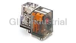
Electromechanical Relay 24VDC 475Ohm 20A 3PDT(35.5x35.6x57)mm Plug-In General Purpose Relay 1-139309...
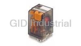
Electromechanical Relay 110VDC 10KOhm 20A 3PDT(35.5x35.6x57)mm Plug-In General Purpose Relay 1-13930...
Electromechanical Relay 220VDC 40KOhm 20A 3PDT(35.5x35.6x57)mm Plug-In General Purpose Relay 1-13930...
Electromechanical Relay 24VDC 475Ohm 20A 3PDT(35.5x35.6x57)mm Plug-In General Purpose Relay 1-139309...
Electromechanical Relay 24VDC 475Ohm 10A 3PDT(35.6x35.5x57)mm Plug-In Industrial Relay 1-1393092-8


Request a Quote

The quote request has been received

Close

Facing challenges or have inquiries? Feel free to contact us!
Call Us +1-469-283-2440
What they say about us
FANTASTIC RESOURCE
One of our top priorities is maintaining our business with precision, and we are constantly looking for affiliates that can help us achieve our goal. With the aid of GID Industrial, our obsolete product management has never been more efficient. They have been a great resource to our company, and have quickly become a go-to supplier on our list!
Bucher Emhart Glass
EXCELLENT SERVICE
With our strict fundamentals and high expectations, we were surprised when we came across GID Industrial and their competitive pricing. When we approached them with our issue, they were incredibly confident in being able to provide us with a seamless solution at the best price for us. GID Industrial quickly understood our needs and provided us with excellent service, as well as fully tested product to ensure what we received would be the right fit for our company.
Fuji
HARD TO FIND A BETTER PROVIDER
Our company provides services to aid in the manufacture of technological products, such as semiconductors and flat panel displays, and often searching for distributors of obsolete product we require can waste time and money. Finding GID Industrial proved to be a great asset to our company, with cost effective solutions and superior knowledge on all of their materials, it’d be hard to find a better provider of obsolete or hard to find products.
Applied Materials
CONSISTENTLY DELIVERS QUALITY SOLUTIONS
Over the years, the equipment used in our company becomes discontinued, but they’re still of great use to us and our customers. Once these products are no longer available through the manufacturer, finding a reliable, quick supplier is a necessity, and luckily for us, GID Industrial has provided the most trustworthy, quality solutions to our obsolete component needs.
Nidec Vamco
TERRIFIC RESOURCE
This company has been a terrific help to us (I work for Trican Well Service) in sourcing the Micron Ram Memory we needed for our Siemens computers. Great service! And great pricing! I know when the product is shipping and when it will arrive, all the way through the ordering process.
Trican Well Service
GO TO SOURCE
When I can't find an obsolete part, I first call GID and they'll come up with my parts every time. Great customer service and follow up as well. Scott emails me from time to time to touch base and see if we're having trouble finding something.....which is often with our 25 yr old equipment.
ConAgra Foods