

 Manufacturers
TE CONNECTIVITY 91349-1

Description
High Speed Backplane Connectors Tools
91349-1
Part Number
91349-1
Price
Request Quote
Manufacturer
TE CONNECTIVITY
Lead Time
Request Quote
Category
Tools and Supplies » Assembly Tools
Specifications
Manufacturer
TE Connectivity
Manufacturers Part #
91349-1
Industry Aliases
91349-1
Sub-Category
Electronics Assembly Tools
Brand
AMP
Factory Pack Quantity
1
Datasheet
DDEController?Action=srchrtrv&DocNm=1773095_Z-PACK_HM-Zd_connectors&DocType=CS&DocLang=English&s_cid=1046.pdf
2418 KiB

Extracted Text
Z-PACK HM-Zd Connector High Speed Backplane Connectors Table of Contents Z-PACK HM-Zd Connector Product Line Overview . . . . . . . . . . . . . . . . . . . . . . . . . . . . . . . . . . . . . . .6 1 4, 3, and 2 Pair Right Angle Receptacle Assemblies . . . . . . . . . . . . . .7-9 4 Pair Vertical Receptacle Assemblies . . . . . . . . . . . . . . . . . . . . . . . . .10 4, 3, and 2 Pair Vertical Pin Header Assemblies . . . . . . . . . . . . . . .11-13 4, 3, and 2 Pair Right Angle Pin Header Assemblies . . . . . . . . . . . .14-16 Power and Guide Hardware . . . . . . . . . . . . . . . . . . . . . . . . . . . . . . .17-23 “New” AdvancedTCA Connectors and Guide/Key Modules . . . . . .24, 25 4 and 2 Pair Pin Headers for Cable Assemblies . . . . . . . . . . . . . . . . . .26 4 and 2 Pair Vertical Pin Headers . . . . . . . . . . . . . . . . . . . . . . . . . . . .26 4 and 2 Pair Right Angle Pin Headers . . . . . . . . . . . . . . . . . . . . . . . .26 4 Pair 5 and 10 Column Push-to-Release Cable Assemblies . . . . . . . .27 2 Pair 5 and 10 Column Push-to-Release Cable Assemblies . . . . . . . .27 4 Pair Cable Assemblies for Backplane Testing . . . . . . . . . . . . . . . . . .27 Recommended Printed Circuit Board Layouts . . . . . . . . . . . . . . . . .28-38 PC Board Routing Guidelines . . . . . . . . . . . . . . . . . . . . . . . . . . . . . . . .39 Connector Housing Gathering Capabilities . . . . . . . . . . . . . . . . . . . . . .40 Mating Sequence Chart . . . . . . . . . . . . . . . . . . . . . . . . . . . . . . . . . . . . .41 Application Tooling and Equipment . . . . . . . . . . . . . . . . . . . . . . . . .42, 43 Compatible 2mm HM Products . . . . . . . . . . . . . . . . . . . . . . . . . . . . . . .44 5 Catalog 1773095 Dimensions are in millimeters Dimensions are shown for USA: 1-800-522-6752 South America: 55-11-3611-1514 Issued 4-05 and inches unless otherwise reference purposes only. Canada: 1-905-470-4425 Hong Kong: 852-2735-1628 specified. Values in brackets Specifications subject Mexico: 01-800-733-8926 Japan: 81-44-844-8013 www.tycoelectronics.com are U.S. equivalents. to change. C. America: 52-55-5-729-0425 UK: 44-141-810-8967 High Speed Backplane Connectors Z-PACK HM-Zd Product Line Overview Product Facts ■ Z-PACK HM-Zd Connector is an extension of the Z-PACK 2mm HM product line ■ Designed specifically for high speed differential applications ■ A modular connector system with a standard module size of 25.00 [.984] ■ Contact pitch is 1.50 [.059] within a pair and 3.00 [.118] pair to pair within a column; column to column pitch is 2.50 [.098] ■ Card Pitch is less than 20.32 [.800] for 2 pair and 3 pair headers and 25.40 [1.000] for 4 pair headers ■ Available in three versions: The Z-PACK HM-Zd switching applications from footprint is optimized for ■ 2 signal contact pairs Connector System is a high 3.125 Gb/s to 10+ Gb/s. both routability and system per column (20 pairs per speed, differential connec- performance with the use of 25.00 [.984]) compatible The Z-PACK HM-Zd tor system, which is com- a 1.50 x 2.50 [.059 x .098] with 5 row Z-PACK Connector System features patible with the Z-PACK row to column grid. The 2mm HM Connector a highly reliable dual beam 2mm HM Connector Line. connector design features a contact system with fully ■ 3 signal contact pairs Z-PACK HM-Zd Connector robust mating interface with encompassing grounds per column (30 pairs per provides Z-PACK 2mm HM integral prealignment and dedicated to each differen- 25.00 [.984]) Connector users with a polarization built into the tial pair. In addition, the ■ 4 signal contact pairs migration path for serial mating interface. Z-PACK HM-Zd Connector per column (40 pairs per 25.00 [.984]) compatible with 8 row Z-PACK Availability 2mm HM Connector Fully validated SPICE models: E-mail requests to modeling@tycoelectronics.com ■ Available in vertical and Samples: go to http://tycoelectronics.custhelp.com right angle press fit pin Pro/E models and IGES models: E-mail requests to TycoCAD@tycoelectronics.com headers and right angle and vertical press fit receptacles White Papers: available on product website at http://hmzd.tycoelectronics.com ■ Optimized footprint for Electrical Performance Report: http://hmzd.tycoelectronics.com improved electrical EPR #20GC014 performance and ease of Routing Guide: http://hmzd.tycoelectronics.com trace routing (unobstructed Routing Guide #20GC015-1 routing channels on both daughtercard and backplane) http://hmzd.tycoelectronics.com ■ Pin header and receptacle have the exact same Technical Documents Material and Finish Ratings footprint to simplify PC Contact Area Finish — 0.80µm Au Current — 0.7A per signal contact, Product Specification board layout min. over 1.3µm Ni min. fully energized 2A per shield, all shields 108-2055 energized Compliant Pin Finish — 0.8µm ■ Designed to meet Telcordia Application Specification SnPb min. over 1.3µm Ni min. Operating Voltage — 114-13059 requirements 500 VAC maximum, signal to signal Contact Material — Copper Alloy Qualification Test Report ■ Recognized under the 250 VAC maximum, signal to ground Housing Material — Glass filled 501-568 Component Program Temperature — –65°C to 105°C polyester, 94V-0 rated of Underwriters Mating Force — 0.38N maximum per Laboratories Inc., contact (signal = 1 contact, ground = R File No. E28476 1 contact) Durability — 250 cycles * Reference Product Spec. 108-2055 for complete list of performance data. 6 Catalog 1773095 Dimensions are in millimeters Dimensions are shown for USA: 1-800-522-6752 South America: 55-11-3611-1514 Issued 4-05 and inches unless otherwise reference purposes only. Canada: 1-905-470-4425 Hong Kong: 852-2735-1628 specified. Values in brackets Specifications subject Mexico: 01-800-733-8926 Japan: 81-44-844-8013 www.tycoelectronics.com are U.S. equivalents. to change. C. America: 52-55-5-729-0425 UK: 44-141-810-8967 Z-PACK HM-Zd Connector High Speed Backplane Connectors Z-PACK HM-Zd Connector 4 Pair Right Angle Receptacle Assemblies 1 ± 0.10 1.00 27.90 2.50 Ref. 0.75 Ref. Ref. ± .004 [.039 ] [1.098] [.098] Typ. [.030] ± 0.08 ± 0.05 19.35 15.67 1.50 Ref. ± .003 ± .002 [.762 ] [.617 ] [.059] Typ. ± 0.08 21.35 ± .003 [.841 ] 2.20 [.087] 3.00 Ref. [.118] Typ. 2.00 3.68 Ref. Ref. Top Surface of [.079] A [.145] 1.50 Ref. Daughtercard 8.70 Ref. [.059] Typ. [.343] 1.50 Ref. [.059] Typ. ± 0.16 ± 0.14 10.70 17.20 ± .006 ± .006 [.421 ] [.677 ] 1 All Plated Thru Holes ± 0.20 1.50 1 PCB Hole Dim. ± .008 [.059 ] ± 0.025 ± .0010 Drilled Hole = 0.7000 [.02756 ] ± 0.05 ± .002 Finished Hole = 0.60 [.024 ] ± 0.0125 ± .00049 Cu Thickness = 0.375 [.0148 ] ± 0.003 ± .0001 SnPb Thickness = 0.007 [.0003 ] 1.50 Typ. [.059] 2.50 Typ. [.098] Note: For finishes other than 9 x 2.50 [.098] = tin-lead, reference Application 22.50 [.886] Specification 114-13059. Recommended PC Board Layout Daughter Board, Component Side Shown 2 Application Tooling Module Column Insertion Repair Part Number Length Signals Grounds Count Housing Chiclet (Dim. A) Receptacle Removal Removal 25.00 1 1 1469001-1 10 80 40 91347-1 1583224-1 1583248-1 .984 30.00 1469286-1 12 96 48 91347-3 1583224-2 1583248-1 1.181 37.50 1469294-1 15 120 60 91347-2 1583224-3 1583248-1 1.476 50.00 1469061-1 20 160 80 91347-4 1583224-4 1583248-1 1.969 1 AdvancedTCA Zone 2 Daughtercard Connector. 2 See page 43 for Instruction Sheet Number. 7 Catalog 1773095 Dimensions are in millimeters Dimensions are shown for USA: 1-800-522-6752 South America: 55-11-3611-1514 Issued 4-05 and inches unless otherwise reference purposes only. Canada: 1-905-470-4425 Hong Kong: 852-2735-1628 specified. Values in brackets Specifications subject Mexico: 01-800-733-8926 Japan: 81-44-844-8013 www.tycoelectronics.com are U.S. equivalents. to change. C. America: 52-55-5-729-0425 UK: 44-141-810-8967 High Speed Backplane Connectors Z-PACK HM-Zd Connector (Continued) 3 Pair Right Angle Receptacle Assemblies ± 0.10 1.00 23.40 2.50 Ref. 0.75 Ref. Ref. ± .004 [.039 ] [.921] [.098] Typ. [.030] 1.50 Ref. [.059] Typ. ± 0.05 11.17 ± 0.08 14.85 ± .002 [.440 ] ± .003 [.585 ] ± 0.08 2.20 16.85 ± .003 [.087] [.663 ] 3.00 Ref. [.118] Typ. 3.68 2.00 Ref. Ref. Top Surface of [.145] A [.079] Daughtercard 8.70 Ref. 1.50 Ref. [.343] [.059] Typ. 1.50 Ref. 1 [.059] Typ. All Plated ± 0.16 ± 0.14 10.70 12.70 Thru Holes ± .006 ± .006 [.421 ] [.500 ] ± 0.20 1.50 ± .008 [.059 ] ± 0.10 1.00 23.22 Ref. ± .004 [.039 ] [.914] 1.50 Typ. [.059] 2.50 Typ. [.098] 9 x 2.50 [.098] = ± 0.05 22.50 [.886] 11.17 ± 0.08 14.85 ± .002 [.440 ] ± .003 [.585 ] Recommended PC Board Layout 2.20 Daughter Board, Component Side Shown ± 0.08 16.85 [.087] ± .003 [.663 ] 1 PCB Hole Dim. ± 0.025 ± .0010 Drilled Hole = 0.7000 [.02756 ] ± 0.05 ± .002 Finished Hole = 0.60 [.024 ] ± 0.0125 ± .00049 Cu Thickness = 0.0375 [.00148 ] ± 0.003 ± .0001 SnPb Thickness = 0.007 [.0003 ] 2.00 3.68 Ref. Ref. Top Surface of [.079] [.145] 1.50 Ref. Daughtercard Note: For finishes other than 8.70 [.059] Typ. Ref. tin-lead, reference Application [.343] Specification 114-13059. 1.50 Ref. [.059] Typ. ± 0.16 ± 0.14 10.70 12.52 ± .006 ± .006 [.421 ] [.493 ] With Notch For PMC Applications 2 Application Tooling Module Column Insertion Repair Part Number Length Signals Grounds Count Housing Chiclet (Dim. A) Receptacle Removal Removal 25.00 1469081-1 10 60 30 91376-1 1583224-1 1673952-1 .984 1 25.00 1 1469514-1 10 60 30 91376-1 1583224-1 1673952-1 .984 1 For CompactPCI and AdvancedTCA PMC Applications. 2 See page 43 for Instruction Sheet Number. CompactPCI is a trademark of PICMG-PCI Industrial Computer Mfg’s. Group. 8 Catalog 1773095 Dimensions are in millimeters Dimensions are shown for USA: 1-800-522-6752 South America: 55-11-3611-1514 Issued 4-05 and inches unless otherwise reference purposes only. Canada: 1-905-470-4425 Hong Kong: 852-2735-1628 specified. Values in brackets Specifications subject Mexico: 01-800-733-8926 Japan: 81-44-844-8013 www.tycoelectronics.com are U.S. equivalents. to change. C. America: 52-55-5-729-0425 UK: 44-141-810-8967 Z-PACK HM-Zd Connector High Speed Backplane Connectors Z-PACK HM-Zd Connector (Continued) 2 Pair Right Angle Receptacle Assemblies ± 0.10 2.50 Ref. 1.00 18.90 0.75 Ref. Ref. 1 ± .004 [.098] Typ. [.039 ] [.744] [.030] 1.50 Ref. [.059] Typ. 8.68 ± 0.05 8.58 Ref. [.342] ± .002 [.338 ] ± 0.08 ± 0.08 13.35 11.35 ± .003 ± .003 [.526 ] [.447 ] 3.00 Ref. [.118] Typ. 0.75 3.68 2.00 Ref. Ref. [.030] [.145] Top Surface of [.079] A Daughtercard 2.20 8.70 Ref. Ref. [.087] [.343] 1.50 Ref. [.059] Typ. 1.50 Ref. 1 [.059] Typ. All Plated ± 0.16 ± 0.14 10.70 8.20 Thru Holes ± .006 ± .006 [.421 ] [.323 ] ± 0.20 1.50 ± .008 [.059 ] 1 PCB Hole Dim. 1.50 Typ. ± 0.025 ± .0010 Drilled Hole = 0.7000 [.02756 ] [.059] ± 0.05 ± .002 Finished Hole = 0.60 [.024 ] 2.50 Typ. ± 0.0125 ± .00049 Cu Thickness = 0.375 [.0148 ] [.098] 9 x 2.50 [.098] = ± 0.003 ± .0001 SnPb Thickness = 0.007 [.0003 ] 22.50 [.886] Note: For finishes other than Recommended PC Board Layout tin-lead, reference Application Daughter Board, Component Side Shown Specification 114-13059. 1 Application Tooling Module Column Insertion Repair Part Number Length Signals Grounds Count (Dim. A) Housing Chiclet Receptacle Removal Removal 25.00 1469028-1 10 40 20 91350-1 1583224-1 1583249-1 .984 50.00 1469077-1 20 80 40 91350-2 1583224-4 1583249-1 1.969 1 See page 43 for Instruction Sheet Number. 9 Catalog 1773095 Dimensions are in millimeters Dimensions are shown for USA: 1-800-522-6752 South America: 55-11-3611-1514 Issued 4-05 and inches unless otherwise reference purposes only. Canada: 1-905-470-4425 Hong Kong: 852-2735-1628 specified. Values in brackets Specifications subject Mexico: 01-800-733-8926 Japan: 81-44-844-8013 www.tycoelectronics.com are U.S. equivalents. to change. C. America: 52-55-5-729-0425 UK: 44-141-810-8967 High Speed Backplane Connectors Z-PACK HM-Zd Connector (Continued) 2.50 Ref. 0.75 4 Pair Vertical Ref. [.098] Typ. [.030] Receptacle Assemblies 1.50 Ref. [.059] Typ. 21.35 [.841] A 19.35 [.762] 1.00 [.039] 14.97 [.589] 2.50 1.50 22.50 [.098] [.059] 7.50 [.886] 1 [.295] Finished 22.50 Outline of Connector Hole Dia. [.886] 1 PCB Hole Dim. ± 0.025 ± .0010 Drilled Hole = 0.7000 [.02756 ] ± 0.05 ± .002 Finished Hole = 0.60 [.024 ] 22.50 Ref. ± 0.0125 ± .00049 Cu Thickness = 0.375 [.0148 ] [.886] 16.50 ± 0.003 ± .0001 SnPb Thickness = 0.007 [.0003 ] [.650] 3.75 [.148] Note: For finishes other than Ref. tin-lead, reference Application Specification 114-13059. 10 1 1.50 [.059] 2.50 [.098] 22.50 [.886] Recommended PC Board Layout 1 Application Tooling Module Column Insertion Repair Part Number Length Signals Grounds Count Housing (Dim. A) Receptacle Removal 25.00 1469362-1* 10 80 40 1804401-1 1804402-1 .984 1 See page 43 for Instruction Sheet Number. * RoHS Compliant. 10 Catalog 1773095 Dimensions are in millimeters Dimensions are shown for USA: 1-800-522-6752 South America: 55-11-3611-1514 Issued 4-05 and inches unless otherwise reference purposes only. Canada: 1-905-470-4425 Hong Kong: 852-2735-1628 specified. Values in brackets Specifications subject Mexico: 01-800-733-8926 Japan: 81-44-844-8013 www.tycoelectronics.com are U.S. equivalents. to change. C. America: 52-55-5-729-0425 UK: 44-141-810-8967 Z-PACK HM-Zd Connector High Speed Backplane Connectors Z-PACK HM-Zd Connector (Continued) 4 Pair Vertical Pin Header Assemblies 2.50 Ref. 2.50 1 [.098] Typ. Ref. [.098] 1.50 Ref. [.059] Typ. 5.675 Ref. [.223] 23.43 Max. [.922] 3.00 Ref. + 0.08 [.118] Typ. 19.65 – 0.20 + .003 [.774 ] – .008 Ref. 1.50 Typ. [.059] 0.75 6.35 ± 0.05 2.95 Ref. [.030] [.250] ± .002 [.116 ] A Ref. ± 0.08 13.40 ± .003 [.528 ] 9 x 2.50 [.098] = 22.50 [.886] 2.50 Typ. [.098] 1 PCB Hole Dim. 1.50 ± 0.025 ± .0010 Typ. Drilled Hole = 0.7000 [.02756 ] [.059] ± 0.05 ± .002 Finished Hole = 0.60 [.024 ] ± 0.0125 ± .00049 Cu Thickness = 0.375 [.0148 ] ± 0.003 ± .0001 SnPb Thickness = 0.007 [.0003 ] 1 All Plated Note: For finishes other than Thru Holes tin-lead, reference Application Recommended PC Board Layout Specification 114-13059. Backplane Component Side Shown 3 Application Tooling Mating Module Part Tail Column Insertion Repair Pin Length Signals Grounds Number Length Count Pin Pin Housing Pin Length (Dim. A) Header Removal Removal Insertion 2.50 5.30 25.00 1 1 1469002-1 10 80 40 91349-1 1583237-1 1583220-1 1583255-1 .098 .209 .984 2 2.50 5.30 25.00 2 1469046-1 10 80 40 91349-1 1583237-1 1583220-1 1583255-1 .098 .209 .984 1.80 5.30 25.00 1469074-1 10 80 40 91349-1 1583237-1 1583220-1 1583255-1 .071 .209 .984 2.50 5.30 30.00 1469287-1 12 96 48 91349-3 1583237-1 1583220-1 1583255-1 .098 .209 1.181 2.50 5.30 37.50 1469296-1 15 120 60 91349-2 1583237-1 1583220-1 1583255-1 .098 .209 1.476 2.50 5.30 50.00 1469062-1 20 160 80 91349-4 1583237-1 1583220-1 1583255-1 .098 .209 1.969 1.80 5.30 50.00 1469099-1 20 160 80 91349-4 1583237-1 1583220-1 1583255-1 .071 .209 1.969 1 AdvancedTCA Zone 2 Backplane Connector. 2 Shallow Wall for Daughtercards thicker than 3.50 [.138]. 3 See page 43 for Instruction Sheet Number. 11 Catalog 1773095 Dimensions are in millimeters Dimensions are shown for USA: 1-800-522-6752 South America: 55-11-3611-1514 Issued 4-05 and inches unless otherwise reference purposes only. Canada: 1-905-470-4425 Hong Kong: 852-2735-1628 specified. Values in brackets Specifications subject Mexico: 01-800-733-8926 Japan: 81-44-844-8013 www.tycoelectronics.com are U.S. equivalents. to change. C. America: 52-55-5-729-0425 UK: 44-141-810-8967 High Speed Backplane Connectors Z-PACK HM-Zd Connector (Continued) 3 Pair Vertical Pin Header Assemblies 2.50 Ref. 2.50 [.098] Typ. Ref. [.098] 1.50 Ref. [.059] Typ. 5.675 Ref. [.223] 18.93 Max. [.745] 3.00 Ref. [.118] Typ. 1.50 Ref. [.059] Typ. 0.75 ± 0.05 2.95 Ref. [.030] 6.35 ± .002 [.116 ] A [.250] Ref. ± 0.08 13.40 ± .003 [.528 ] 9 x 2.50 [.098] = 22.50 [.886] 2.50 Typ. [.098] 1 PCB Hole Dim. 1.50 ± 0.025 ± .0010 Typ. Drilled Hole = 0.7000 [.02756 ] [.059] ± 0.05 ± .002 Finished Hole = 0.60 [.024 ] ± 0.0125 ± .00049 Cu Thickness = 0.0375 [.00148 ] ± 0.003 ± .0001 SnPb Thickness = 0.007 [.0003 ] 1 All Plated Thru Holes Note: For finishes other than tin-lead, reference Application Recommended PC Board Layout Specification 114-13059. Backplane, Component Side Shown 1 Application Tooling Mating Module Part Tail Column Insertion Repair Pin Length Signals Grounds Number Length Count Pin Pin Housing Pin Length (Dim. A) Header Removal Removal Insertion 2.50 5.30 25.00 1469083-1 10 60 30 91375-1 1583237-1 1725634-1 1583255-1 .098 .209 .984 1.80 5.30 25.00 1469085-1 10 60 30 91375-1 1583237-1 1725634-1 1583255-1 .071 .209 .984 1 See page 43 for Instruction Sheet Number. 12 Catalog 1773095 Dimensions are in millimeters Dimensions are shown for USA: 1-800-522-6752 South America: 55-11-3611-1514 Issued 4-05 and inches unless otherwise reference purposes only. Canada: 1-905-470-4425 Hong Kong: 852-2735-1628 specified. Values in brackets Specifications subject Mexico: 01-800-733-8926 Japan: 81-44-844-8013 www.tycoelectronics.com are U.S. equivalents. to change. C. America: 52-55-5-729-0425 UK: 44-141-810-8967 Z-PACK HM-Zd Connector High Speed Backplane Connectors Z-PACK HM-Zd Connector (Continued) 2 Pair Vertical Pin Header Assemblies 1 2.50 Ref. 2.50 Ref. [.098] Typ. [.098] 1.50 Ref. [.059] Typ. 5.675 Ref. [.223] 15.43 Max. [.607] + 0.08 11.65 – 0.20 1.50 Typ. + .003 [.459 ] – .008 [.059] Ref. 3.00 Ref. [.118] Typ. ± 0.05 0.75 2.95 Ref. 6.35 ± .002 [.030] [.116 ] Ref. A [.250] ± 0.08 13.40 ± .003 [.528 ] 9 x 2.50 [.098] = 22.50 [.886] 2.50 Typ. [.098] 1 PCB Hole Dim. ± 0.025 ± .0010 Drilled Hole = 0.7000 [.02756 ] ± 0.05 ± .002 Finished Hole = 0.60 [.024 ] ± 0.0125 ± .00049 Cu Thickness = 0.375 [.0148 ] ± 0.003 ± .0001 SnPb Thickness = 0.007 [.0003 ] 1 1.50 Typ. [.059] All Plated Note: For finishes other than Thru Holes tin-lead, reference Application Recommended PC Board Layout Specification 114-13059. Backplane 1 Application Tooling Mating Module Part Tail Column Insertion Repair Pin Length Signals Grounds Number Length Count Length (Dim. A) Pin Pin Housing Pin Header Removal Removal Insertion 2.50 5.30 25.00 1469025-1 10 40 20 91348-1 1583237-1 1583234-1 1583255-1 .098 .209 .984 1.80 5.30 25.00 1469076-1 10 40 20 91348-1 1583237-1 1583234-1 1583255-1 .071 .209 .984 2.50 5.30 50.00 1469078-1 20 80 40 91348-4 1583237-1 1583234-1 1583255-1 .098 .209 1.969 1.80 5.30 50.00 1469101-1 20 80 40 91348-4 1583237-1 1583234-1 1583255-1 .071 .209 1.969 1 See page 43 for Instruction Sheet Number. 13 Catalog 1773095 Dimensions are in millimeters Dimensions are shown for USA: 1-800-522-6752 South America: 55-11-3611-1514 Issued 4-05 and inches unless otherwise reference purposes only. Canada: 1-905-470-4425 Hong Kong: 852-2735-1628 specified. Values in brackets Specifications subject Mexico: 01-800-733-8926 Japan: 81-44-844-8013 www.tycoelectronics.com are U.S. equivalents. to change. C. America: 52-55-5-729-0425 UK: 44-141-810-8967 High Speed Backplane Connectors Z-PACK HM-Zd Connector (Continued) 4 Pair Right Angle Pin Header Assemblies 34.55 2.50 Ref. 1.65 Ref. Ref. [1.360] [.098] Typ. [.065] Typ. 17.32 [.682] 1.50 Ref. Ref. [.059] Typ. 19.65 Ref. [.774] 17.68 [.696] 2.20 23.35 Ref. Ref. [.087] [.919] Ref. 3.00 Ref. [.118] Typ. 5.30 2.00 Top Surface of 5.675 Ref. [.209] [.079] Daughtercard [.223] A Ref. Ref. 1.50 Ref. [.059] Typ. 6.35 1.50 Ref. [.250] [.059] Typ. Ref. 10.45 6.90 17.20 Ref. Ref. Ref. [.411] [.272] [.677] 1 All Plated Thru Holes ± 0.20 1.50 1 PCB Hole Dim. ± .008 [.059 ] ± 0.025 ± .0010 Drilled Hole = 0.7000 [.02756 ] ± 0.05 ± .002 Finished Hole = 0.60 [.024 ] ± 0.0125 ± .00049 Cu Thickness = 0.0375 [.00148 ] ± 0.003 ± .0001 SnPb Thickness = 0.007 [.0003 ] 1.50 [.059] 2.50 Typ. [.098] Note: For finishes other than 9 x 2.50 [.098] = tin-lead, reference Application 22.50 [.886] Specification 114-13059. Recommended PC Board Layout Component Side Shown 1 Application Tooling Mating Module Part Tail Column Insertion Repair Pin Length Signals Grounds Number Length Count Length (Dim. A) Pin Housing Chiclet Header Removal Removal 2.20 5.30 25.00 1469048-1 10 80 40 91378-1 1804174-1 1804177-1 .087 .209 .984 2.20 5.30 30.00 1469375-1 12 96 48 91378-3 1804174-1 1804177-1 .087 .209 1.181 1 See page 43 for Instruction Sheet Number. 14 Catalog 1773095 Dimensions are in millimeters Dimensions are shown for USA: 1-800-522-6752 South America: 55-11-3611-1514 Issued 4-05 and inches unless otherwise reference purposes only. Canada: 1-905-470-4425 Hong Kong: 852-2735-1628 specified. Values in brackets Specifications subject Mexico: 01-800-733-8926 Japan: 81-44-844-8013 www.tycoelectronics.com are U.S. equivalents. to change. C. America: 52-55-5-729-0425 UK: 44-141-810-8967 Z-PACK HM-Zd Connector High Speed Backplane Connectors Z-PACK HM-Zd Connector (Continued) 3 Pair Right Angle Pin Header Assemblies 1 30.05 2.50 Ref. 1.65 Ref. Ref. [1.183] [.098] Typ. [.065] Typ. 13.31 Ref. 1.50 Ref. [.524] [.059] Typ. 15.15 Ref. [.596] 2.20 18.99 Ref. [.087] [.747] Ref. 3.00 Ref. [.118] Typ. 5.30 2.00 Top Surface of 5.675 [.209] [.079] Daughtercard Ref. A [.223] Ref. Ref. 1.50 Ref. [.059] Typ. 6.35 1.50 Ref. [.250] [.059] Typ. Ref. 10.45 6.90 12.70 Ref. Ref. Ref. [.411] [.272] [.500] 1 All Plated Thru Holes ± 0.20 1.50 1 PCB Hole Dim. ± .008 [.059 ] ± 0.025 ± .0010 Drilled Hole = 0.7000 [.02756 ] ± 0.05 ± .002 Finished Hole = 0.60 [.024 ] ± 0.0125 ± .00049 Cu Thickness = 0.0375 [.00148 ] ± 0.003 ± .0001 SnPb Thickness = 0.007 [.0003 ] 1.50 Typ. [.059] 2.50 Typ. Note: For finishes other than [.098] 9 x 2.50 [.098] = tin-lead, reference Application 22.50 [.886] Specification 114-13059. Recommended PC Board Layout Component Side Shown 1 Application Tooling Mating Module Part Tail Column Insertion Repair Pin Length Signals Grounds Number Length Count Pin Housing Chiclet Length (Dim. A) Header Removal Removal 2.20 5.30 25.00 1469183-1 10 60 30 1804179-1 1804173-1 1804176-1 .087 .209 .984 1 See page 43 for Instruction Sheet Number. 15 Catalog 1773095 Dimensions are in millimeters Dimensions are shown for USA: 1-800-522-6752 South America: 55-11-3611-1514 Issued 4-05 and inches unless otherwise reference purposes only. Canada: 1-905-470-4425 Hong Kong: 852-2735-1628 specified. Values in brackets Specifications subject Mexico: 01-800-733-8926 Japan: 81-44-844-8013 www.tycoelectronics.com are U.S. equivalents. to change. C. America: 52-55-5-729-0425 UK: 44-141-810-8967 High Speed Backplane Connectors Z-PACK HM-Zd Connector (Continued) 2 Pair Right Angle Pin Header Assemblies 25.55 2.50 Ref. 1.65 Ref. Ref. [1.006] [.098] Typ. [.065] Typ. 1.50 Ref. [.059] Typ. 9.81 Ref. [.386] 11.65 Ref. 2.20 [.459] [.087] 15.49 Ref. Ref. [.610] 3.00 Ref. [.118] Typ. 5.30 2.00 5.675 Top Surface of Ref. [.209] [.079] [.223] Daughtercard A Ref. Ref. 1.50 Ref. 6.35 [.059] Typ. 1.50 Ref. [.250] [.059] Typ. Ref. 10.45 6.90 8.20 Ref. Ref. Ref. [.411] [.272] [.323] All Plated 1 Thru Holes ± 0.20 1.50 1 PCB Hole Dim. ± .008 ± 0.025 ± .0010 [.059 ] Drilled Hole = 0.7000 [.02756 ] ± 0.05 ± .002 Finished Hole = 0.60 [.024 ] ± 0.0125 ± .00049 Cu Thickness = 0.0375 [.00148 ] ± 0.003 ± .0001 SnPb Thickness = 0.007 [.0003 ] 1.50 [.059] 2.50 Typ. Note: For finishes other than [.098] 9 x 2.50 [.098] = tin-lead, reference Application 22.50 [.886] Specification 114-13059. Recommended PC Board Layout Component Side Shown 1 Application Tooling Mating Module Part Tail Column Insertion Repair Pin Length Signals Grounds Number Length Count Pin Housing Chiclet Length (Dim. A) Header Removal Removal 2.20 5.30 25.00 1469169-1 10 40 20 91377-1 1804171-1 1804175-1 .087 .209 .984 1 See page 43 for Instruction Sheet Number. 16 Catalog 1773095 Dimensions are in millimeters Dimensions are shown for USA: 1-800-522-6752 South America: 55-11-3611-1514 Issued 4-05 and inches unless otherwise reference purposes only. Canada: 1-905-470-4425 Hong Kong: 852-2735-1628 specified. Values in brackets Specifications subject Mexico: 01-800-733-8926 Japan: 81-44-844-8013 www.tycoelectronics.com are U.S. equivalents. to change. C. America: 52-55-5-729-0425 UK: 44-141-810-8967 Z-PACK HM-Zd Connector High Speed Backplane Connectors Z-PACK HM-Zd Connector (Continued) Power and Guide Hardware Universal Power Module Vertical Receptacle (3 Pos.) 1 The Tyco Electronics The right angle header Universal Power Module is contacts are available with a three position, modular, sequenced lengths for Hard Metric board-to-board “make-first/break-last” power connector designed applications. to be compatible with Generous alignment features Z-PACK 2mm HM designed into the housings Connectors. The design is and optional guide pins in an “inverse-sex” orienta- and receptacles make the tion and the vertical recep- Tyco Electronics Universal tacle module meets the IEC Power Module ideal for 950 safety requirements for “blind mating” applications. finger probe protection. Both the headers and recep- tacle utilize Tyco Electronics ACTION PIN press-fit leads for ease of assembly onto printed circuit boards. Additionally, the vertical receptacle leads are polar- ized to allow only one orien- 3.70 9.62 tation onto the printed [.146] [.379] Mating Point circuit board, eliminating the possibility of reverse placement. The Universal Power 9.95 11.35 9.50 Module is compatible with [.392] [.447] [.374] a wide variety of other Tyco Electronics board-to- board connectors including Z-PACK HS3, Z-PACK 12.15 HM-Zd, Z-PACK Strip-line [.478] 100, AMP-HDI, TBC, TBC Plus and Eurocard 3.00 connectors. [.118] 2.00 The housings are thermo- [.079] plastic and the contacts are offered in either a standard Vertical Position Part Receptacle or high current copper Loaded Numbers Outline alloy. Contact finish is gold ABC 223955-2 Vertical over nickel on the mating Receptacle AC 223984-1 surfaces. The contacts High Current ABC 5-223955-2 are designed to carry 10 6.00 amperes per contact in [.236] 3.00 standard assemblies and [.118] 15 amperes per contact in the high current assemblies. 2.50 Ref. [.098] Actual values may vary Ref. 1 PCB Hole Dim. depending upon connector ± 0.025 ± .0010 Drilled Hole = 0.7000 [.02756 ] ± 0.05 ± .002 Finished Hole = 0.60 [.024 ] size, board design, etc. 1 ± 0.0125 ± .00049 Cu Thickness = 0.375 [.0148 ] Plated Thru Hole Top Surface of ± 0.003 ± .0001 SnPb Thickness = 0.007 [.0003 ] (12 Plcs.) Daughtercard Ref. 1.50 Ref. Note: For finishes other than [.059] tin-lead, reference Application Ref. Recommended PC Board Hole Layout Specification 114-1103. 17 Catalog 1773095 Dimensions are in millimeters Dimensions are shown for USA: 1-800-522-6752 South America: 55-11-3611-1514 Issued 4-05 and inches unless otherwise reference purposes only. Canada: 1-905-470-4425 Hong Kong: 852-2735-1628 specified. Values in brackets Specifications subject Mexico: 01-800-733-8926 Japan: 81-44-844-8013 www.tycoelectronics.com are U.S. equivalents. to change. C. America: 52-55-5-729-0425 UK: 44-141-810-8967 High Speed Backplane Connectors Z-PACK HM-Zd Connector (Continued) 3.00 0.50 Power and Guide Hardware [.118] [.020] (Continued) Expanded Universal Power Module Vertical Receptacles 2.00 2.00 [.079] ± 0.05 12.15 [.079] ± 0.05 9.95 0.75 ± .002 Material and Finish [.478 ] ± .002 [.392 ] [.030] Ø 0.20 At Post ± 0.08 11.35 3.00 Typ. [.008] Tip Typ. Housing — Polyester, gray ± .003 [.447 ] [.118] Contact — Copper alloy, plated ± 0.28 ± 0.30 3.70 9.62 0.00127 [.000050] min. gold in mating ± .011 ± .012 1.00 [.146 ] [.379 ] Ref. area, 0.00050 [.000020] min. tin-lead [.039] Mating Point on ACTION PIN area, with entire contact underplated 0.00127 [.000050] min. nickel 0.75 A Ref. [.030] Spaces At ± 0.05 B 3.00 ± .002 [ ] Related Product Data [.118] Guiding Hardware (Optional) — pages 21-23 2.50 Application Tooling Ref. [.098] Header 2.00 3.00 Seating Tool, 224441-1 [.079] [.118] Board Support Fixture, 224442-1 2.00 1 Top Surface of [.079] Receptacle Daughter Card Plated Through Hole Seating Tool, 224421-1 Ref. 48 Plcs. Board Support Fixture, 217602-1 1 PCB Hole Dim. ± 0.025 ± .0010 Drilled Hole = 0.7000 [.02756 ] A Technical Documents ± 0.05 ± .002 Finished Hole = 0.60 [.024 ] Spaces ± 0.0125 ± .00049 Cu Thickness = 0.375 [.0148 ] Product Specification At ± 0.003 ± .0001 SnPb Thickness = 0.007 [.0003 ] 3.00 108-1651 [.118] Application Specification Note: For finishes other than 114-1103 tin-lead, reference Application Tyco Electronics Instruction Sheet Specification 114-1103. 408-4169 (Receptacle Seating Tool 224421-1) 1.50 Ref. [.059] Recommended PCB Hole Layout Standard High Current B Position A *10A *15A Ref. Part Number Part Number 12.50 43 223995-1 120953-1 .492 15.50 54 223995-2 120953-2 .610 18.50 65 223995-3 120953-3 .728 21.50 76 223995-4 120953-4 .846 24.50 87 223995-5 120953-5 .965 *Reference Product Specification 108-1651. Note: For additional Power Module options reference Catalog 1773096, "Power Connectors and Interconnection Systems,” or contact your Tyco Electronics Sales Representative. 18 Catalog 1773095 Dimensions are in millimeters Dimensions are shown for USA: 1-800-522-6752 South America: 55-11-3611-1514 Issued 4-05 and inches unless otherwise reference purposes only. Canada: 1-905-470-4425 Hong Kong: 852-2735-1628 specified. Values in brackets Specifications subject Mexico: 01-800-733-8926 Japan: 81-44-844-8013 www.tycoelectronics.com are U.S. equivalents. to change. C. America: 52-55-5-729-0425 UK: 44-141-810-8967 Z-PACK HM-Zd Connector High Speed Backplane Connectors Z-PACK HM-Zd Connector (Continued) Power and Guide Hardware 3.00 (Continued) [.118] 1 Universal Power Module 12.00 Max. [.472] Right Angle Headers (3 Pos.) 3.00 Material and Finish [.118] Housing — polyester, natural color ± 0.13 14.60 Contacts — Copper alloy, plated ± .005 [.575 ] 0.00127 [.000050] min. gold in mating area, 0.00050 [.000020] min. tin-lead ± 0.08 12.00 ± .003 [.472 ] on ACTION PIN post area, with entire contact underplated 0.00127 [.000050] min. nickel 10.90 Ref. [.429] ± 0.08 9.70 ± .003 [.382 ] 6.00 Typ. [.236] 2.25 [.089] ± 0.25 3.22 2.00 Typ. ± .010 [.127 ] [.079] Position A Position C ± 0.08 11.70 Position B 4.00 ± .003 [.461 ] Ref. [.157] ± 0.05 9.75 15.70 ± .002 [.384 ] [.618] 1 3.50 2.00 Typ. All Plated 1.50 [.138] [.079] Through Hole [.059] 12 Plcs. 3.00 1.50 Typ. [.118] [.059] 1 PCB Hole Dim. ± 0.025 ± .0010 Drilled Hole = 0.7000 [.02756 ] ± 0.05 ± .002 Finished Hole = 0.60 [.024 ] 3.00 ± 0.0125 ± .00049 Cu Thickness = 0.375 [.0148 ] [.118] 2.98 Ref. ± 0.003 ± .0001 SnPb Thickness = 0.007 [.0003 ] [.117] 2 Plcs. ± 0.05 Ø 2.00 Thru Hole Note: For finishes other than ± .002 [.079 ] 2 Plcs. tin-lead, reference Application Specification 114-1103. Recommended PC Board Hole Layout Standard High Current Blade Length Dimensions *10A *15A Right Angle Header Right Angle Header Position A Position B Position C Part Numbers Part Numbers 10.90 [.429] 10.90 [.429] 10.90 [.429] 223961-1 5-223961-1 10.90 [.429] 9.30 [.366] 10.90 [.429] 223962-1 — 10.90 [.429] 9.30 [.366] 9.30 [.366] 223968-1 — 10.90 [.429] 7.68 [.302] 10.90 [.429] 223972-1 — 10.90 [.429] 7.68 [.302] 9.30 [.366] 223971-1 — 10.90 [.429] 7.68 [.302] 7.68 [.302] 223970-1 — 9.30 [.429] 10.90 [.429] 9.30 [.366] 223963-1 — 9.30 [.366] 10.90 [.429] 7.68 [.302] 223964-1 — 9.30 [.366] 9.30 [.366] 9.30 [.366] 223967-1 — 9.30 [.366] — 9.30 [.366] 223975-1 — 9.30 [.366] 9.30 [.366] 7.68 [.302] 223981-1 — Note: For additional Power Module 9.30 [.366] 7.68 [.302] 9.30 [.366] 223965-1 — options reference Catalog 7.68 [.302] 9.30 [.366] 7.68 [.302] 223983-1 — 1773096, "Power Connectors 7.68 [.302] 7.68 [.302] 9.30 [.366] 223980-1 — and Interconnection Systems,” or contact your 7.68 [.302] 7.68 [.302] 7.68 [.302] 223974-1 5-223974-1 Tyco Electronics Sales *Reference Product Specification 108-1651. Representative. 19 Catalog 1773095 Dimensions are in millimeters Dimensions are shown for USA: 1-800-522-6752 South America: 55-11-3611-1514 Issued 4-05 and inches unless otherwise reference purposes only. Canada: 1-905-470-4425 Hong Kong: 852-2735-1628 specified. Values in brackets Specifications subject Mexico: 01-800-733-8926 Japan: 81-44-844-8013 www.tycoelectronics.com are U.S. equivalents. to change. C. America: 52-55-5-729-0425 UK: 44-141-810-8967 High Speed Backplane Connectors Z-PACK HM-Zd Connector (Continued) 22.34 Power and Guide Hardware [.880] (Continued) Expanded Universal Power Module Right Angle Headers A Max. 3.00 Typ. [.118] Material and Finish Housing — Polyester, gray 11.38 Contacts — Phosphor bronze, plated Ref. [.448] 0.00127 [.000050] min. gold in mating 13.00 area, 0.00054 [.000021] min. tin-lead Ref. ± 0.10 [.512] 0.04 on ACTION PIN area, with entire contact ± .004 [.016 ] ± 0.13 14.60 underplated 0.00127 [.000050] min. Typ. ± .005 [.575 ] nickel ± 0.08 12.00 ± .003 [.472 ] 1.20 Min. 10.90 [.047] 4 Plcs. Ref. [.429] 6.00 Related Product Data [.236] Guiding Hardware (Optional) — Typ. ± 0.08 9.70 pages 21-23 ± .003 [.382 ] 10.26 Typ. 14.33 [.404] [.564] Application Tooling Ref. Header 2.25 [.089] Seating Tool, 224441-1 2.00 3.13 Typ. Board Support Fixture, 224442-1 [.079] [.123] ± 0.08 11.70 ± 0.25 B 3.22 ± .003 Receptacle [.461 ] 4.00 ± .010 [.127 ] Ref. [.157] Seating Tool, 224421-1 15.70 3.50 [.618] Board Support Fixture, 217602-1 2.00 [.138] Typ. 1.50 [.079] [.059] Technical Documents 1 Product Specification 1.50 All Plated 1 PCB Hole Dim. 108-1651 [.059] Through Hole ± 0.025 ± .0010 Drilled Hole = 0.7000 [.02756 ] 16 Plcs. Application Specification ± 0.05 ± .002 Finished Hole = 0.60 [.024 ] ± 0.0125 ± .00049 6.00 Cu Thickness = 0.375 [.0148 ] 114-1103 3.00 ± 0.003 ± .0001 [.236] Typ. SnPb Thickness = 0.007 [.0003 ] [.118] Tyco Electronics Instruction Sheet 408-4169 (Receptacle Note: For finishes other than Seating Tool 224421-1) tin-lead, reference Application 2.98 Ref. Specification 114-1103. [.117] 2 Plcs. ± 0.05 Ø 2.00 Thru Hole ± .002 [.079 ] 2 Plcs. Recommended PC Board Hole Layout Standard High Current Dimensions Positions *10A *15A AB 1 1 Base Part Number Base Part Number 15.00 12.75 2 4 646954 120954 .591 .502 18.00 15.75 2 5 646955 120955 .709 .620 21.00 18.75 2 6 646956 120956 .827 .738 24.00 21.75 2 7 646957 120957 .945 .856 27.00 24.75 2 8 646958 120958 1.063 .974 Note: For additional Power Module options reference Catalog 1 Dash number indicates sequence pattern. See customer drawing for specific dash numbers. 1773096, "Power Connectors 2 RoHS Compliant. and Interconnection *Reference Product Specification 108-1651. Systems,” or contact your Tyco Electronics Sales Representative. 20 Catalog 1773095 Dimensions are in millimeters Dimensions are shown for USA: 1-800-522-6752 South America: 55-11-3611-1514 Issued 4-05 and inches unless otherwise reference purposes only. Canada: 1-905-470-4425 Hong Kong: 852-2735-1628 specified. Values in brackets Specifications subject Mexico: 01-800-733-8926 Japan: 81-44-844-8013 www.tycoelectronics.com are U.S. equivalents. to change. C. America: 52-55-5-729-0425 UK: 44-141-810-8967 Z-PACK HM-Zd Connector High Speed Backplane Connectors Z-PACK HM-Zd Connector (Continued) Power and Guide Hardware (Continued) 1 Guide Pin (Unkeyed) See Chart 7.80 Dia. [.307] Material and Finish Guide Pin — Passivated stainless steel Part Number 223956-1 4.85 Dia. [.191] Dia. LOCTITE sealant B applied in this area. A Dimension Thread Part Numbers AB 1, 2 7.50 [.295] 24.73 [.974] M4 x 7-6g 223982-1 2 9.20 [.362] 25.16 [.991] M4 x 7-6g 223969-7 2 12.70 [.500] 25.16 [.991] 8-32 UNC-2A 223969-4 2 12.70 [.500] 25.16 [.991] M4 x 7-6g 223969-1 2 6.20 [.244] 25.16 [.991] M4 x 7-6g 223956-1 2 12.70 [.500] 31.25 [1.230] 8-32 UNC-2A 1-223969-0 3 2 3.80 [.150] 27.16 [1.069] M4 x 7-6h 120646-1 3 2 2.00 [.079] 27.16 [1.069] M3 x 0.5 223988-1 1 6.35 Hex Base. 2 RoHS Compliant. 3 Internal Thread. Female Guide Module (Unkeyed) Material and Finish Guide Module — Zinc alloy, chromate conversion coated 7.90 Related Product Data [.311] Application Tooling — Seating Tool, 224440-1. 9.70 Board Support Fixture, 217603-1. [.382] 5.50 5.40 Dia. [.217] Technical Documents [.213] 4.00 Product Specification [.157] 108-1651 ± 0.08 3.175 Dia. ± .003 [.125 ] Application Specification Drilled Hole 3.95 Ref. 114-1103 2 Plcs. [.156] Part Number 223957-1 4-40 UNC-2B (as shown) 34.20 Part Number 223979-1 [1.346] (dual alignment posts) 15.00 [.591] 5.75 [.226] 11.00 [.443] Recommended PC Board Hole Layout 21 Catalog 1773095 Dimensions are in millimeters Dimensions are shown for USA: 1-800-522-6752 South America: 55-11-3611-1514 Issued 4-05 and inches unless otherwise reference purposes only. Canada: 1-905-470-4425 Hong Kong: 852-2735-1628 specified. Values in brackets Specifications subject Mexico: 01-800-733-8926 Japan: 81-44-844-8013 www.tycoelectronics.com are U.S. equivalents. to change. C. America: 52-55-5-729-0425 UK: 44-141-810-8967 R 0.50 [.020] High Speed Backplane Connectors Z-PACK HM-Zd Connector (Continued) 6.35 Power and Guide Hardware A ± 0.05 Ø 4.85 3.85 [.250] + 0.04 ± .002 Ø 8.70 [.191 ] B (Continued) – 0.10 [.152] 1.00 + .002 [.343 ] – .004 24° Ref. [.039] Guide Pin (Unkeyed) ± 0.05 ± 0.08 Ø 4.82 5.92 ± .002 ± .003 [.190 ] [.233 ] Material and Finish 1.70 [.067] ± 0.05 4.14 Ø 1.00 Guide Pin — Zinc alloy, chromate ± .002 6-32 UNC-2B [.163 ] [.039] conversion coated 6.00 Deep ± 0.05 [.236] Part Number 223985 Ø 1.10 45° Typ. ± .002 [.043 ] 0.50 [.020] Dimension Part Number AB ± 0.05 3.85 ± .002 [.152 ] 25.16 20.39 Row E HM Connector C 223985-1 L .991 .803 ± 0.05 Ø 5.00 29.00 24.23 223985-3 ± .002 [.197 ] 1.142 .954 Recommended PC Board Layout (Position Shown Used with Part Number 223986-1) 34.20 Female Guide Module [1.346] (Unkeyed) 26.70 [1.051] Material and Finish Guide Module — Zinc alloy, chromate conversion coated + 0.05 Part Number 223986 7.90 ± 0.08 9.70 – 0.10 + .002 A ± .003 [.382 ] [.311 ] – .009 ± 0.08 Ø 5.40 2.82 ± .003 Ref. [.213 ] [.111] 1.67 4.00 [.066] [.157] Dim. Part Thread ± 0.08 A Number Ø 7.40 5.50 ± .003 [.291 ] 0° 4-40 223986-1 [.216] ± 0.10 3.02 45° 4-40 223986-2 ± 0.05 4.40 ± .004 [.119 ] ± 0.08 3.37 ± .002 [.173 ] 90° 4-40 223986-3 2 Plcs. 16.75 15.00 ± .003 [.133 ] [.659] [.591] 135° 4-40 223986-4 180° 4-40 223986-5 225° 4-40 223986-6 270° 4-40 223986-7 Threaded Hole — See Table 315° 4-40 223986-8 7.50 0° M2.6 120913-1 [.295] 45° M2.6 120913-2 90° M2.6 120913-3 11.00 15.00 [.433] [.591] 135° M2.6 120913-4 180° M2.6 120913-5 225° M2.6 120913-6 270° M2.6 120913-7 315° M2.6 120913-8 ± 0.08 Ø 3.175 5.75 ± .003 [.125 ] [.226] 2 Plcs. Footprint 22 Catalog 1773095 Dimensions are in millimeters Dimensions are shown for USA: 1-800-522-6752 South America: 55-11-3611-1514 Issued 4-05 and inches unless otherwise reference purposes only. Canada: 1-905-470-4425 Hong Kong: 852-2735-1628 specified. Values in brackets Specifications subject Mexico: 01-800-733-8926 Japan: 81-44-844-8013 www.tycoelectronics.com are U.S. equivalents. to change. C. America: 52-55-5-729-0425 UK: 44-141-810-8967 Z-PACK HM-Zd Connector High Speed Backplane Connectors Z-PACK HM-Zd Connector (Continued) 7.40 Power and Guide Hardware A [.291] (Continued) ± 0.015 ± 0.05 0.80 Ø 5.15 Rad. ± .0006 ± .002 [.031 ] [.203 ] 1 ± 0.05 3.80 Rad. ± .002 [.150 ] PCB Layout for Guidepost Note: Key hole orientation (Dim. A) per mating guide module Part Number table (Orientation 2.00 shown on PCB layout is for [.079] 32.00 [1.260] Part Number 1410297-2). 1410773 Series Contact, ESD Housing Hole for Positive Retention Screw 6.00 Ground Pad [.236] Ø 5.00 [.197] on 18.40 4.00 Retention Hardware [.724] 2 Plcs. ± 0.05 Ø 3.96 [.157] 2 Plcs. Side of PCB ± .002 [.156 ] ± 0.05 Ø 3.96 5.63 ± .002 [.156 ] [.222] 12.25 3.70 5.50 5.00 - Z - [.482] [.146] [.217] [.197] 31.88 [1.255] 16.13 - Y - [.635] Edge of Daughtercard 12.50 [.492] 10.70 [.421] Top of Motherboard 5.63 Ref. PCB Layout [.222] 12.25 Connector Side [.482] Ref. 1410297 Series 32.00 5.70 [1.260] [.224] A ± 0.015 ± 0.05 0.80 Ø 5.15 Rad. ± .0006 ± .002 [.031 ] [.203 ] ± 0.05 3.80 Rad. ± .002 [.150 ] 6.99 4.65 [.275] PCB Layout for Guidepost [.183] Note: Key hole orientation (Dim. A) per mating guide module Part Number table (Orientation 6.50 [.256] 28.95 shown on PCB layout is for [1.140] Part Number 1410297-2). 1410548 Series MULTIGIG RT Guide Modules Description Part Number Keyed/ESD Guide Module Assembly, 20.30 [.799] Daughtercard* 1410297-X Keyed Guide Pin, Backplane Connector, Threaded Post** 1410773-X Keyed Guide Pin, Die Cast, Rolling Thunder, Backplane Connector** 1410548-X * See customer drawing for specific keying options. ** Internal and external threaded versions available, see customer drawings for available options. 23 Catalog 1773095 Dimensions are in millimeters Dimensions are shown for USA: 1-800-522-6752 South America: 55-11-3611-1514 Issued 4-05 and inches unless otherwise reference purposes only. Canada: 1-905-470-4425 Hong Kong: 852-2735-1628 specified. Values in brackets Specifications subject Mexico: 01-800-733-8926 Japan: 81-44-844-8013 www.tycoelectronics.com are U.S. equivalents. to change. C. America: 52-55-5-729-0425 UK: 44-141-810-8967 High Speed Backplane Connectors Z-PACK HM-Zd Connector (Continued) “NEW” AdvancedTCA Connectors AdvancedTCA Zone 2 Front Board Connector 4 Pair Right Angle Receptacle Part Number 1469001-1 See page 7 for more details Front Board Connector Backplane Connector Backplane Connector 4 Pair Vertical Header Part Number 1469002-1 See page 11 for more details AdvancedTCA Guide/Keying Modules The AdvancedTCA Guide Modules can be used in a wide variety of applications. For motherboard-to- daughtercard applications rA1 A2 (RTM) K1/K2 the vertical pin and right angle socket are used. This popular configuration is further supported by our wide offering of available keying positions. Each of the two keyed guide pins and guide sockets per module can be produced in a variety of different key rK1 A1 A2 positions. For co-planar applications, the right angle ATCA Name ATCA Location Description Part Number guide pins are used along Rear Alignment Post rA1 Backplane 1469269-2* with the right angle guide 3.00 – 4.00 [.118 – .157] PCB Thickness sockets. Both vertical and Rear Alignment Post rA1 Backplane 1469269-4* right angle guide pins are 4.10 – 6.00 [.161 – .236] PCB Thickness available in short or long Rear Alignment Post rA1 Backplane 1469269-6* 6.10 – 8.00 [.240 – .315] PCB Thickness sizes, to accommodate A2 (RTM) Rear Transition Module Right Angle Male, Keyed 1-1469372-1* being used with different K1/K2 Front Board Right Angle Female, Keyed 1-1469373-1* Tyco Electronics connectors. K1/K2 Front Board Right Angle Female, Unkeyed Dummy 9-1469373-9* rK1 Rear Transition Right Angle Female 1469374-1* A1 Backplane Vertical Male, Keyed, Short 1-1469387-1* A2 Mid-Plane Vertical Male, Keyed, Long 1-1469388-1* * RoHS Compliant. 24 Catalog 1773095 Dimensions are in millimeters Dimensions are shown for USA: 1-800-522-6752 South America: 55-11-3611-1514 Issued 4-05 and inches unless otherwise reference purposes only. Canada: 1-905-470-4425 Hong Kong: 852-2735-1628 specified. Values in brackets Specifications subject Mexico: 01-800-733-8926 Japan: 81-44-844-8013 www.tycoelectronics.com are U.S. equivalents. to change. C. America: 52-55-5-729-0425 UK: 44-141-810-8967 NEW! Z-PACK HM-Zd Connector High Speed Backplane Connectors Z-PACK HM-Zd Connector (Continued) 22.20 46.10 AdvancedTCA Ref. 1.00 [.874] [1.815] See Note 2 6.02 Power Connectors (Zone 1) [.039] 1 [.237] 10.45 Max. Backplane Connector 28 30 13 17 21 [.411] 1 25 33 20.90 32 Straight, Compliant Press Fit, 27 Max. 34 [.823] 26 16 20 24 29 Part Number 1766501-1* 31 4 Material and Finish 28.60 17.50 Max. Insulators — Thermoplastic, glass 5.30 [1.126] [.689] [.207] reinforced, black, UL94V-0 Max. 4.60 [.180] Signal Pins — Copper alloy See Note 1 Power Contacts — High conductivity 3.90 6.00 Ø 2.50 2 Plcs. [.154] [.236] copper alloy, plated 0.0076 [.000030] [.098] 2.00 min. gold in mating area per 6.60 2.20 [.079] 4.50 [.260] [.087] 4.50 [.177] Tyco Electronics Specification 112-162-5, 9.59 [.177] over 0.00130 [.000050] min. nickel per [.378] Tyco Electronics Specification 112-25-2 Solder tails — 0.0030 - 0.0043 Ø 1.60 8 Plcs. [.000120 - .000170] tin plated per lead [.063] 2.20 6.60 10.00 [.087] free Tyco Electronics Specification [.260] [.394] 12.00 112-65-1, matt finish 3.90 [.472] Ø 1.00 14.50 [.154] [.039] [.571] 3.00 Notes: 26 Plcs. [.118] 9.40 1. Mounting Holes (Ş2.00 [.079] x [.370] 13.70 5.00 [.197] DP) for use with self Ø 1.75 [.539] tapping screw (customer supplied). 18.50 [.069] 2. Positions 1–4 not populated and [.728] 21.20 reserved for future use. [.835] 22.55 [.888] 23.90 [.941] 26.60 [1.047] Printed Circuit Layout 46.10 41.30 Front Board Connector Ref. Max. [1.815] [1.626] See Note 1 Right Angle, 1 10.45 Compliant Press Fit Max. 21 17 13 33 30 28 25 [.411] Part Number 1766500-1* 20.90 4.60 5.30 27 Max. 32 [.823] [.180] [.207] Material and Finish 34 31 29 26 24 20 16 Insulators — Thermoplastic, glass 4 17.50 28.60 reinforced, black, UL94V-0 Max. [.689] [1.126] Signal Pins — Copper alloy Max. 18.65 [.734] See Note 2 Power Contacts — High conductivity 26.60 copper alloy, plated 0.00076 [.000030] [1.047] 23.90 min. gold in mating area per [.941] 21.20 Tyco Electronics Specification 112-162-5, [.835] 18.50 over 0.00130 [.000050] min. nickel per [.728] 13.70 Tyco Electronics Specification 112-25-2 [.539] 9.40 [.370] Solder Tails — 0.0030 - 0.0043 3.00 Ø 1.00 [.000120 - .000170] tin plated per lead [.118] 26 Plcs. [.039] 12.00 free Tyco Electronics Specification [.472] Ø 1.60 2.20 3.90 6.60 112-65-1, matt finish 8 Plcs. [.063] [.087] [.154] [.260] 12.47 Notes: [.491] 1. Mounting Holes (Ş 2.00 [.079] x 5.00 [.197] DP) for use with self tapping screw (customer supplied). 4.50 [.177] 2. Positions 1–4 not populated and 4.50 reserved for future use. [.177] Ø 1.70 2.20 6.60 Ø 2.50 [.067] [.087] [.260] 22.55 2 Plcs. * RoHS Compliant [.098] 2 Plcs. [.888] 3.90 2.00 [.154] [.079] 24.50 6.00 [.965] [.236] 10.00 [.394] 13.40 [.528] 14.50 [.571] Printed Circuit Layout 25 Catalog 1773095 Dimensions are in millimeters Dimensions are shown for USA: 1-800-522-6752 South America: 55-11-3611-1514 Issued 4-05 and inches unless otherwise reference purposes only. Canada: 1-905-470-4425 Hong Kong: 852-2735-1628 specified. Values in brackets Specifications subject Mexico: 01-800-733-8926 Japan: 81-44-844-8013 www.tycoelectronics.com are U.S. equivalents. to change. C. America: 52-55-5-729-0425 UK: 44-141-810-8967 High Speed Backplane Connectors Z-PACK HM-Zd Connector (Continued) Vertical Pin Headers for Cable Assemblies 2 Application Tooling Mating Pair Part Tail Column Module Insertion Repair Pin Signals Grounds Count Number Length Count Length Pin Pin Housing Pin Length Header Removal Removal Insertion 2.50 5.30 25.00 1 4 1469105-1 10 80 40 91373-1 1583237-1 1725635-1 1583255-1 .098 .209 .984 1.80 5.30 25.00 1 4 1469124-1 10 80 40 91373-1 1583237-1 1725635-1 1583255-1 .071 .209 .984 2.50 5.30 25.00 1 2 1469106-1 10 40 20 91372-1 1583237-1 1804170-1 1583255-1 .098 .209 .984 1.80 5.30 25.00 1 2 1469125-1 10 40 20 91372-1 1583237-1 1804170-1 1583255-1 .071 .209 .984 1 With latch for cable assemblies. 2 See page 43 for Instruction Sheet Number. For PCB Layout, see pages 11-13. Right Angle Pin Headers for Cable Assemblies 2 Application Tooling Mating Pair Part Tail Column Module Insertion Repair Pin Signals Grounds Count Number Length Count Length Pin Housing Chiclet Length Header Removal Removal 2.20 5.30 25.00 4 1469668-1 10 80 40 1804244-1 1804239-1 1804177-1 .087 .209 .984 2.20 5.30 25.00 1 2 1469354-1 10 40 20 1804178-1 1804172-1 1804175-1 .087 .209 .984 1 With latch for cable assemblies. 2 See page 43 for Instruction Sheet Number. For PCB Layout, see pages 14-16. 26 Catalog 1773095 Dimensions are in millimeters Dimensions are shown for USA: 1-800-522-6752 South America: 55-11-3611-1514 Issued 4-05 and inches unless otherwise reference purposes only. Canada: 1-905-470-4425 Hong Kong: 852-2735-1628 specified. Values in brackets Specifications subject Mexico: 01-800-733-8926 Japan: 81-44-844-8013 www.tycoelectronics.com are U.S. equivalents. to change. C. America: 52-55-5-729-0425 UK: 44-141-810-8967 Z-PACK HM-Zd Connector High Speed Backplane Connectors Z-PACK HM-Zd Connector (Continued) 4 Pair 5 Column and 4 Pair 10 Column Push-to-Release Cable 1 Assemblies Note: Design shown for reference only. Contact Tyco Electronics for other variations and configurations. 2 Pair 5 Column and 2 Pair 10 Column Push-to-Release Cable Assemblies Note: Design shown for reference only. Contact Tyco Electronics for other variations and configurations. 4 Pair Cable Assemblies for Backplane Testing Note: Design shown for reference only. Contact Tyco Electronics for other variations and configurations. 27 Catalog 1773095 Dimensions are in millimeters Dimensions are shown for USA: 1-800-522-6752 South America: 55-11-3611-1514 Issued 4-05 and inches unless otherwise reference purposes only. Canada: 1-905-470-4425 Hong Kong: 852-2735-1628 specified. Values in brackets Specifications subject Mexico: 01-800-733-8926 Japan: 81-44-844-8013 www.tycoelectronics.com are U.S. equivalents. to change. C. America: 52-55-5-729-0425 UK: 44-141-810-8967 High Speed Backplane Connectors Z-PACK HM-Zd Connector (Continued) 2.70 2.13 Recommended Printed 4 Pair Top Surface of See Detail Z [.106] [.084] Daughtercard Circuit Board Layouts Row B Z-PACK HM-Zd Backplane and Z-PACK 2mm HM Connectors 0.10 Min. Typ. [.004] Gap 2.70 2.13 [.106] [.084] 24 Spaces @ 9 Spaces @ 24 Spaces @ 2.00 [.079] = 48.00 [1.890] 2.50 [.098] 2.00 [.079] = 48.00 [1.890] = 22.50 [.886] Row B Reference Spec. Ø 0.010 Typ. Detail Z 4 Spaces @ 114-19029 for [.0004] 2.00 [.079] Hole Dimensions Reference Spec. Reference Spec. 7 Spaces @ = 8.00 [.315] 125 Plcs. 114-13059 for 114-19029 for 11 Spaces @ 2.00 [.079] Hole Dimensions Hole Dimensions 1.50 [.059] = 16.50 [.650] = 14.00 [.551] 60 Plcs. 200 Plcs. Note: 1. Dimensions shown represent 2.70 1.80 3 Pair Top Surface of minimum stacking dimensions See Detail Z [.106] [.071] Daughtercard allowable. Customer specific applications will dictate actual module spacing. Row B 2.70 1.80 [.106] [.071] 24 Spaces @ 9 Spaces @ 24 Spaces @ 2.00 [.079] = 48.00 [1.890] 2.50 [.098] 2.00 [.079] = 48.00 [1.890] = 22.50 [.886] Row B Reference Spec. Ø 0.010 Typ. 114-19029 for 4 Spaces @ [.0004] Hole Dimensions 2.00 [.079] Reference Spec. Reference Spec. 7 Spaces @ 125 Plcs. = 8.00 [.315] 114-13059 for 114-19029 for 8 Spaces @ 2.00 [.079] Hole Dimensions Hole Dimensions 1.50 [.059] = 12.00 [.472] = 14.00 [.551] 60 Plcs. 200 Plcs. 2.70 1.80 2 Pair Top Surface of See Detail Z [.106] [.071] Daughtercard Row B 2.70 1.80 [.106] [.071] 24 Spaces @ 9 Spaces @ 24 Spaces @ 2.00 [.079] = 48.00 [1.890] 2.50 [.098] 2.00 [.079] = 48.00 [1.890] = 22.50 [.886] Row B Reference Spec. Ø 0.010 Typ. 114-19029 for 4 Spaces @ [.0004] Hole Dimensions 2.00 [.079] 5 Spaces @ Reference Spec. Reference Spec. 7 Spaces @ 125 Plcs. = 8.00 [.315] 1.50 [.059] = 7.50 [.295] 114-13059 for 114-19029 for 2.00 [.079] Hole Dimensions Hole Dimensions = 14.00 [.551] 60 Plcs. 200 Plcs. 28 Catalog 1773095 Dimensions are in millimeters Dimensions are shown for USA: 1-800-522-6752 South America: 55-11-3611-1514 Issued 4-05 and inches unless otherwise reference purposes only. Canada: 1-905-470-4425 Hong Kong: 852-2735-1628 specified. Values in brackets Specifications subject Mexico: 01-800-733-8926 Japan: 81-44-844-8013 www.tycoelectronics.com are U.S. equivalents. to change. C. America: 52-55-5-729-0425 UK: 44-141-810-8967 Z-PACK HM-Zd Connector High Speed Backplane Connectors Z-PACK HM-Zd Connector (Continued) Recommended Printed 4 Pair Circuit Board Layouts (Continued) 1 Row B Z-PACK HM-Zd Daughtercard 2.70 2.13 Top Surface of and Z-PACK 2mm HM [.106] [.084] Daughtercard Connectors 24 Spaces @ 9 Spaces @ 24 Spaces @ 2.00 [.079] = 48.00 [1.890] 2.50 [.098] 2.00 [.079] = 48.00 [1.890] = 22.50 [.886] 2.70 2.13 [.106] [.084] Ø 0.010 [.0004] Reference Spec. 1.50 Reference Spec. Reference Spec. 4 Spaces @ 11 Spaces @ 114-19029 for [.059] 114-19029 for 114-13059 for 2.00 [.079] 1.50 [.059] = Hole Dimensions Hole Dimensions Hole Dimensions = 8.00 [.315] 16.50 [.650] 200 Plcs. 7 Spaces @ 125 Plcs. 60 Plcs. 2.00 [.079] PC Board Edge = 14.00 [.551] Note: 1. Dimensions shown represent 3 Pair minimum stacking dimensions allowable. Customer specific applications will dictate actual module spacing. Row B 2.70 1.80 Top Surface of [.106] [.071] Daughtercard 24 Spaces @ 9 Spaces @ 24 Spaces @ 2.00 [.079] = 48.00 [1.890] 2.50 [.098] 2.00 [.079] = 48.00 [1.890] = 22.50 [.886] 1.80 2.70 [.071] Ø 0.010 [.106] [.0004] Reference Spec. 1.50 Reference Spec. Reference Spec. 4 Spaces @ 8 Spaces @ 114-19029 for [.059] 114-19029 for 114-13059 for 2.00 [.079] 1.50 [.059] = Hole Dimensions Hole Dimensions Hole Dimensions = 8.00 [.315] 12.00 [.472] 200 Plcs. 7 Spaces @ 125 Plcs. 60 Plcs. 2.00 [.079] PC Board Edge = 14.00 [.551] 2 Pair Row B 2.70 1.80 Top Surface of [.106] [.071] Daughtercard 24 Spaces @ 9 Spaces @ 24 Spaces @ 2.00 [.079] = 48.00 [1.890] 2.50 [.098] 2.00 [.079] = 48.00 [1.890] = 22.50 [.886] 1.80 2.70 [.071] Ø 0.010 [.106] [.0004] Reference Spec. 1.50 Reference Spec. 4 Spaces @ Reference Spec. 5 Spaces @ 114-19029 for [.059] 114-19029 for 2.00 [.079] 114-13059 for 1.50 [.059] = Hole Dimensions Hole Dimensions = 8.00 [.315] Hole Dimensions 7.50 [.295] 200 Plcs. 7 Spaces @ 125 Plcs. 60 Plcs. 2.00 [.079] PC Board Edge = 14.00 [.551] 29 Catalog 1773095 Dimensions are in millimeters Dimensions are shown for USA: 1-800-522-6752 South America: 55-11-3611-1514 Issued 4-05 and inches unless otherwise reference purposes only. Canada: 1-905-470-4425 Hong Kong: 852-2735-1628 specified. Values in brackets Specifications subject Mexico: 01-800-733-8926 Japan: 81-44-844-8013 www.tycoelectronics.com are U.S. equivalents. to change. C. America: 52-55-5-729-0425 UK: 44-141-810-8967 High Speed Backplane Connectors Z-PACK HM-Zd Connector (Continued) Recommended Printed Circuit Board Layouts (Continued) A B Ref. Ref. C of Signal Cavities C of Signal Cavities L L Top Surface of Daughtercard Z-PACK HM-Zd Backplane Row B Connector with Unkeyed Guide Pins 5.50 Ref. [.217] Top Surface of Daughtercard Row B 5.50 Ref. [.217] C of Guide Pin L Top Surface of Daughtercard Row B Note: 1. Dimensions shown represent minimum stacking dimensions 5.50 Ref. [.217] allowable. Customer specific applications will dictate actual C of Guide Pin L module spacing. Typ. E Ref. 1 Typ. Ref. Annular Ring PEM Nut Part Number KSF-M4 C Ref. D Ref. 8.74 Ref. [.344] Dimension Part Number ABCD E 5.25 6.15 0.40 1.30 0.60 223956* .207 .242 .016 .051 .024 5.52 6.42 0.65 1.55 0.42 223985 .217 .253 .026 .061 .017 * RoHS Compliant. 30 Catalog 1773095 Dimensions are in millimeters Dimensions are shown for USA: 1-800-522-6752 South America: 55-11-3611-1514 Issued 4-05 and inches unless otherwise reference purposes only. Canada: 1-905-470-4425 Hong Kong: 852-2735-1628 specified. Values in brackets Specifications subject Mexico: 01-800-733-8926 Japan: 81-44-844-8013 www.tycoelectronics.com are U.S. equivalents. to change. C. America: 52-55-5-729-0425 UK: 44-141-810-8967 Z-PACK HM-Zd Connector High Speed Backplane Connectors Z-PACK HM-Zd Connector (Continued) Recommended Printed Circuit Board Layouts (Continued) 1 Z-PACK HM-Zd Daughtercard Connector With Unkeyed Female Guide Modules 20.75 Ref. [.817] 5.75 Ref. [.226] 11.00 Ref. [.433] A B Ref. Ref. Typ. C Ref. C of Guide Module L Note: 1. Dimensions shown represent minimum stacking dimensions allowable. Customer specific 5.50 Row B applications will dictate actual Ref. [.217] module spacing. Top Surface of Daughtercard C of Signal Cavities C of Signal Cavities L L C of Guide Module L 5.50 Row B Ref. [.217] Top Surface of Daughtercard C of Guide Module L 5.50 Row B Ref. [.217] Top Surface of Daughtercard Dimension Part Number ABC 5.25 6.15 0.56 223957 .207 .242 .022 5.52 6.42 0.83 223986 .217 .253 .033 31 Catalog 1773095 Dimensions are in millimeters Dimensions are shown for USA: 1-800-522-6752 South America: 55-11-3611-1514 Issued 4-05 and inches unless otherwise reference purposes only. Canada: 1-905-470-4425 Hong Kong: 852-2735-1628 specified. Values in brackets Specifications subject Mexico: 01-800-733-8926 Japan: 81-44-844-8013 www.tycoelectronics.com are U.S. equivalents. to change. C. America: 52-55-5-729-0425 UK: 44-141-810-8967 High Speed Backplane Connectors Z-PACK HM-Zd Connector (Continued) Recommended Printed Circuit Board Layouts (Continued) 1.55 Ref. [.061] Typ. Top Surface of Z-PACK HM-Zd Backplane Daughtercard Row B Connector and Universal Power Modules Top Surface of Daughtercard Row B Top Surface of Daughtercard Row B Note: 1. Dimensions shown represent minimum stacking dimensions allowable. Customer specific applications will dictate actual module spacing. 2.50 Ref. [.098] 3.30 5.70 Ref. Ref. [.130] [.224] 1.00 Reference Spec. [.039] 114-13059 for Ref. Hole Dimensions for HM-Zd 1.50 Ref. [.059] 3.00 Ref. [.118] Top Surface of Daughtercard Reference Spec. Connector Outline 114-1103 for Hole Dimensions for Power Module Recommended PC Board Layout Component Side 32 Catalog 1773095 Dimensions are in millimeters Dimensions are shown for USA: 1-800-522-6752 South America: 55-11-3611-1514 Issued 4-05 and inches unless otherwise reference purposes only. Canada: 1-905-470-4425 Hong Kong: 852-2735-1628 specified. Values in brackets Specifications subject Mexico: 01-800-733-8926 Japan: 81-44-844-8013 www.tycoelectronics.com are U.S. equivalents. to change. C. America: 52-55-5-729-0425 UK: 44-141-810-8967 Z-PACK HM-Zd Connector High Speed Backplane Connectors Z-PACK HM-Zd Connector (Continued) Recommended Printed Circuit Board Layouts (Continued) 1 Z-PACK HM-Zd Daughtercard Connector and Universal Power Modules 12.20 Ref. [.480] 0.325 Ref. See Recommended [.013] Typ. PC Board Layout Note: Top Surface of Daughtercard 1. Dimensions shown represent minimum stacking dimensions Row B allowable. Customer specific applications will dictate actual module spacing. Top Surface of Daughtercard Row B Top Surface of Daughtercard Row B Reference Spec. 114-1103 for Hole Dimensions 4.05 Ref. for Power Module [.159] Reference Spec. 114-13059 for Hole Dimensions for HM-Zd 2.00 Ref. [.079] Leading Edge of Daughtercard 1.50 1.50 4.95 Ref. Ref. Ref. [.059] [.059] [.195] Recommended PC Board Layout Component Side 33 Catalog 1773095 Dimensions are in millimeters Dimensions are shown for USA: 1-800-522-6752 South America: 55-11-3611-1514 Issued 4-05 and inches unless otherwise reference purposes only. Canada: 1-905-470-4425 Hong Kong: 852-2735-1628 specified. Values in brackets Specifications subject Mexico: 01-800-733-8926 Japan: 81-44-844-8013 www.tycoelectronics.com are U.S. equivalents. to change. C. America: 52-55-5-729-0425 UK: 44-141-810-8967 High Speed Backplane Connectors Z-PACK HM-Zd Connector (Continued) Recommended Printed Circuit Board Layouts (Continued) 6.42 7.32 Ref. Ref. [.253] [.288] C of Signal Cavities C of Signal Cavities L L Z-PACK HM-Zd Backplane Connector and MULTIGIG RT Top Surface of Daughtercard Connector Guide Modules Row B 6.00 Ref. [.236] C of Guide Pin L Top Surface of Daughtercard Row B 6.00 Ref. [.236] C of Guide Pin L Note: Top Surface of 1. Dimensions shown represent Daughtercard minimum stacking dimensions Row B allowable. Customer specific applications will dictate actual module spacing. 6.00 Ref. [.236] C of Guide Pin L 10.00 Ref. [.394] 0.67 Typ. [.026] Ref. 34 Catalog 1773095 Dimensions are in millimeters Dimensions are shown for USA: 1-800-522-6752 South America: 55-11-3611-1514 Issued 4-05 and inches unless otherwise reference purposes only. Canada: 1-905-470-4425 Hong Kong: 852-2735-1628 specified. Values in brackets Specifications subject Mexico: 01-800-733-8926 Japan: 81-44-844-8013 www.tycoelectronics.com are U.S. equivalents. to change. C. America: 52-55-5-729-0425 UK: 44-141-810-8967 Z-PACK HM-Zd Connector High Speed Backplane Connectors Z-PACK HM-Zd Connector (Continued) Recommended Printed Circuit Board Layouts (Continued) 1 Z-PACK HM-Zd Daughtercard Connector and MULTIGIG RT Connector Guide Modules 17.25 Ref. [.679] 5.00 Ref. [.197] 10.75 Ref. [.423] 6.42 Ref. 7.32 [.253] Ref. 0.32 Ref. [.288] [.013] Typ. Note: 1. Dimensions shown represent C of Guide Module L minimum stacking dimensions allowable. Customer specific applications will dictate actual module spacing. Row B 6.00 Ref. [.236] Top Surface of Daughtercard C of Signal Cavities C of Signal Cavities L L C of Guide Module L Row B 6.00 Ref. [.236] Top Surface of Daughtercard C of Guide Module L Row B 6.00 Ref. [.236] Top Surface of Daughtercard 35 Catalog 1773095 Dimensions are in millimeters Dimensions are shown for USA: 1-800-522-6752 South America: 55-11-3611-1514 Issued 4-05 and inches unless otherwise reference purposes only. Canada: 1-905-470-4425 Hong Kong: 852-2735-1628 specified. Values in brackets Specifications subject Mexico: 01-800-733-8926 Japan: 81-44-844-8013 www.tycoelectronics.com are U.S. equivalents. to change. C. America: 52-55-5-729-0425 UK: 44-141-810-8967 High Speed Backplane Connectors Z-PACK HM-Zd Connector (Continued) Recommended Printed Circuit Board Layouts (Continued) Top Surface of Daughtercard and Centerline of Row B, C L For Both Connector Pairs, Are Coplanar. See Note 2. Z-PACK HM-Zd Connector Recommended Mid-Plane Layout Option #1 0.90 Ref. [.035] Pin Identification: Row A / Column 1 See Note 2. Backplane Notes: Thickness 1. Minimum recommended back- plane thicknesses calculated Tail Length using maximum and minimum Typ. tolerances. No statistical methods Pin Identification: were used. Row A / Column 10 2. Refer to the customer print for See Note 2. complete column and row desig- nations. C L Tail Min. Recommended Length Backplane Thickness 1.80 4.00 .071 .157 2.50 5.40 .098 .213 36 Catalog 1773095 Dimensions are in millimeters Dimensions are shown for USA: 1-800-522-6752 South America: 55-11-3611-1514 Issued 4-05 and inches unless otherwise reference purposes only. Canada: 1-905-470-4425 Hong Kong: 852-2735-1628 specified. Values in brackets Specifications subject Mexico: 01-800-733-8926 Japan: 81-44-844-8013 www.tycoelectronics.com are U.S. equivalents. to change. C. America: 52-55-5-729-0425 UK: 44-141-810-8967 Z-PACK HM-Zd Connector High Speed Backplane Connectors Z-PACK HM-Zd Connector (Continued) Recommended Printed Circuit Board Layouts (Continued) 12.00 Ref. 1 [.472] Z-PACK HM-Zd Connector Recommended Mid-Plane Layout Option #2 Pin Identification: Row A / Column 1 See Note 2. Tail Length Typ. Backplane Notes: Thickness 1. Minimum recommended back- plane thicknesses calculated using maximum and minimum See Note 3. tolerances. No statistical methods were used. Pin Identification: 2. Refer to the customer print for Row H / Column 1 See Note 2. complete column and row desig- nations. 3. An additional row of holes must be drilled to accommo- date this midplane application. is coplanar C L Tail Min. Recommended Length Backplane Thickness 1.80 4.00 .071 .157 2.50 5.40 .098 .213 37 Catalog 1773095 Dimensions are in millimeters Dimensions are shown for USA: 1-800-522-6752 South America: 55-11-3611-1514 Issued 4-05 and inches unless otherwise reference purposes only. Canada: 1-905-470-4425 Hong Kong: 852-2735-1628 specified. Values in brackets Specifications subject Mexico: 01-800-733-8926 Japan: 81-44-844-8013 www.tycoelectronics.com are U.S. equivalents. to change. C. America: 52-55-5-729-0425 UK: 44-141-810-8967 High Speed Backplane Connectors Z-PACK HM-Zd Connector (Continued) Recommended Printed Circuit Board Layouts (Continued) Z-PACK HM-Zd Connector Coplanar HM-Zd Right Angle Header HM-Zd Right Angle Receptacle 4 Pair 4 Pair 17.80 Min. [.701] For Coplanar Applications Centerlines of Holes on Receptacle PCB To Be Aligned To Holes in Header PCB 38 Catalog 1773095 Dimensions are in millimeters Dimensions are shown for USA: 1-800-522-6752 South America: 55-11-3611-1514 Issued 4-05 and inches unless otherwise reference purposes only. Canada: 1-905-470-4425 Hong Kong: 852-2735-1628 specified. Values in brackets Specifications subject Mexico: 01-800-733-8926 Japan: 81-44-844-8013 www.tycoelectronics.com are U.S. equivalents. to change. C. America: 52-55-5-729-0425 UK: 44-141-810-8967 Z-PACK HM-Zd Connector High Speed Backplane Connectors Z-PACK HM-Zd Connector (Continued) Z-PACK HM-Zd Connector Footprint and PC Board Trace Routing 1 ■ Accounts for system design requirements ■ Footprint is optimized for low noise and ease of routing ■ Footprint permits wide traces for long runs and without having to separate differential pairs ■ Footprint supports quad routing techniques (see below) Notes Regarding Quad Benefits of Quad Routing Routing: ■ Better Platform 1. Within pin field, center Characteristics signal pairs between ■ Performance variation Standard 4 Layers signal columns due to layer connection is reduced 2. Trace separation is increased over “standard” ■ Crosstalk is reduced recommendations to ■ Return loss is reduced QuadRoute further limit trace to trace ■ Enables a lower cost 2 Layers crosstalk solution 3. Recommend Quad ■ Cost of better materials Routing pairs together is offset by reduced that are propagating in processing the same direction ■ Increased manufactura- bility—less layers and decreased aspect ratios 4.75 5.25 4.75 13.25 4.75 5.25 4.75 ■ Decreased number of [.187] [.207] [.187] [.522] [.187] [.207] [.187] layers reduces the need for counterboring of PC boards 2.92 Notes Regarding Antipad [.115] Design: 1. An oval shaped antipad may be used to increase PC board manufactura- 1.22 bility and to improve [.048] trace break-out 2. Antipad length shown is 2.92 [.114]. An antipad 1.50 length up to 3.48 [.137] [.059] may be used. For further details request Report # 20GC015-1 or visit http://catalog.tycoelectronics.com/TE/GeneralInfo/footprint_optimization.pdf 39 Catalog 1773095 Dimensions are in millimeters Dimensions are shown for USA: 1-800-522-6752 South America: 55-11-3611-1514 Issued 4-05 and inches unless otherwise reference purposes only. Canada: 1-905-470-4425 Hong Kong: 852-2735-1628 specified. Values in brackets Specifications subject Mexico: 01-800-733-8926 Japan: 81-44-844-8013 www.tycoelectronics.com are U.S. equivalents. to change. C. America: 52-55-5-729-0425 UK: 44-141-810-8967 High Speed Backplane Connectors Z-PACK HM-Zd Connector (Continued) Connector Housing Gathering Capabilities 1.48 Offset [.058] 1.65 Offset C of Receptacle [.065] L C of Receptacle L 24.55 25.20 Ref. Ref. [.967] [.992] Note: Dimensions are at nominal conditions. The offsets are to be applied to either side of the header C of Header C center line. of Header L L 40 Catalog 1773095 Dimensions are in millimeters Dimensions are shown for USA: 1-800-522-6752 South America: 55-11-3611-1514 Issued 4-05 and inches unless otherwise reference purposes only. Canada: 1-905-470-4425 Hong Kong: 852-2735-1628 specified. Values in brackets Specifications subject Mexico: 01-800-733-8926 Japan: 81-44-844-8013 www.tycoelectronics.com are U.S. equivalents. to change. C. America: 52-55-5-729-0425 UK: 44-141-810-8967 Z-PACK HM-Zd Connector High Speed Backplane Connectors Z-PACK HM-Zd Connector (Continued) Z-PACK HM-Zd Connector Mating Sequence Chart 1 Fully Mated Reliable Mate Dim B. Dim. A Product Fully Mated Dim.CFully Contact Reliable First Mate Family Wipe Length Mated Mate Last Break Ground Shield 16.78 [.661] 17.55 [.691] 4.28 [.169] 1.50 12.50 HM-Zd Signal Level 2 15.41 [.607] 15.85 [.624] 2.91 [.115] .059 .492 Signal Level 1 13.91 [.548] 14.35 [.565] 1.41 [.056] 24.0 mm Pin 27.50 [1.083] 33.40 [1.315] N/A HM-Zd 3.00 12.50 Guide 22.2 mm Pin 25.70 [1.012] 31.60 [1.244] N/A .118 .492 Hardware Key Blocking Point N/A 22.03 [.867] N/A Signal Level 3 18.27 [.719] 18.84 [.742] 5.77 [.227] 1.50 12.50 HM-2mm Signal Level 2 16.77 [.660] 17.34 [.683] 4.27 [.168] .059 .492 Signal Level 1 15.27 [.601] 15.84 [.624] 2.77 [.109] Ground 18.00 [.709] — 5.50 [.217] Signal Level 3 18.00 [.709] — 5.50 [.217] MULTIGIG RT 2.50 12.50 T1 .098 .492 Signal Level 2 16.50 [.650] — 4.00 [.157] Signal Level 1 15.00 [.591] — 2.50 [.098] Ground 18.00 [.709] — 5.50 [.217] Signal Level 3 18.00 [.709] — 5.50 [.217] MULTIGIG RT 2.25 12.50 T2 .089 .492 Signal Level 2 16.50 [.650] — 4.00 [.157] Signal Level 1 15.00 [.591] — 2.50 [.098] Ground 16.50 [.650] — 4.00 [.157] MULTIGIG RT 2.25 12.50 T3 .089 .492 Signal Level 1 15.00 [.591] — 2.50 [.098] Power Level 3 23.75 [.935] — 11.25 [.443] MULTIGIG RT 5.50 12.50 Power Power Level 2 22.25 [.876] — 9.75 [.384] .217 .492 Module Power Level 1 20.75 [.817] — 8.25 [.325] MULTIGIG RT Guide Pin Key 33.25 [1.309] N/A 20.75 [.817] 12.50 Guide N/A .492 Guide ESD Contact 30.75 [1.211] — 18.25 [.719] Hardware Ground 17.08 [.672] 17.60 [.693] 4.78 [.188] 1.50 12.50 HS-3 Signal Level 2 16.05 [.632] 16.47 [.648] 3.75 [.148] .059 .492 Signal Level 1 14.55 [.573] 14.97 [.589] 2.25 [.089] Power Level 3 20.25 [.797] 20.95 [.825] 8.10 [.319] 3.50 12.50 UPM Power Level 2 18.65 [.734] 19.35 [.762] 6.50 [.256] .138 .492 Power Level 1 17.03 [.670] 17.73 [.698] 4.88 [.192] Guide Pin Key 31.39 [1.236] 36.16 [1.424] N/A UPM 5.75 12.50 Guide Keyed Guide Pin 31.39 [1.236] 36.16 [1.424] N/A .226 .492 Hardware Keyed Guide Pin 35.23 [1.387] 40.00 [1.575] N/A PreMate Power — 5.61 [.221] — 16.84 [.663] Level 1 Min. MULTI-BEAM XL PostMate Power — 4.34 [.171] — 17.81 [.701] Right Angle Level 2 Min. 5.08 14.73 Header to .200 .580 PreMate Signal — 3.81 [.150] Vertical — 18.26 [.719] Level 2 Min. Receptacle PostMate Signal — 2.54 [.100] — 19.53 [.769] Level 3 Min. PreMate Power — 5.61 [.221] — 15.32 [.603] Level 1 Min. MULTI-BEAM XL PostMate Power — 4.34 [.171] — 16.28 [.641] Right Angle Level 2 Min. 3.81 13.21 Receptacle .150 .520 PreMate Signal — 3.81 [.150] to Vertical — 16.74 [.659] Level 2 Min. Header PostMate Signal — 2.54 [.100] — 18.01 [.709] Level 3 Min. 41 Catalog 1773095 Dimensions are in millimeters Dimensions are shown for USA: 1-800-522-6752 South America: 55-11-3611-1514 Issued 4-05 and inches unless otherwise reference purposes only. Canada: 1-905-470-4425 Hong Kong: 852-2735-1628 specified. Values in brackets Specifications subject Mexico: 01-800-733-8926 Japan: 81-44-844-8013 www.tycoelectronics.com are U.S. equivalents. to change. C. America: 52-55-5-729-0425 UK: 44-141-810-8967 High Speed Backplane Connectors Z-PACK HM-Zd Connector (Continued) Z-PACK HM-Zd Connector Application Tooling and Equipment 1585280-1 Model AP3 1585696-1 Model BMEP 5T 1585699-1 Model MEP 6T Typical Manual Arbor Frame Assembly (Commercially Available) Typical PC Board Support Typical Receptacle Seating Tool Typical Pin Header Seating Tool Typical Chiclet Removal Tool (Customer Supplied) IS 408-8500 IS 408-8501 IS 408-8647 Typical Receptacle Housing Removal Tool IS 408-8644 Typical Pin (Post) Extraction Tool IS 408-8646 Typical Header Removal Tools IS 408-8645 Typical Pin (Post) Insertion Tool IS 408-8648 Note: Typical power units from Tyco Electronics Automation Group include, but are not limited to those shown on this page. 42 Catalog 1773095 Dimensions are in millimeters Dimensions are shown for USA: 1-800-522-6752 South America: 55-11-3611-1514 Issued 4-05 and inches unless otherwise reference purposes only. Canada: 1-905-470-4425 Hong Kong: 852-2735-1628 specified. Values in brackets Specifications subject Mexico: 01-800-733-8926 Japan: 81-44-844-8013 www.tycoelectronics.com are U.S. equivalents. to change. C. America: 52-55-5-729-0425 UK: 44-141-810-8967 Z-PACK HM-Zd Connector High Speed Backplane Connectors Z-PACK HM-Zd Connector (Continued) Z-PACK HM-Zd Connector Type Description Instruction Sheet Part Number Seating Tool, Receptacle, 4 Pair, 10 Column 408-8500 91347-1 Application Tooling and Seating Tool, Receptacle, 4 Pair, 15 Column 408-8500 91347-2 Equipment (Continued) 1 Seating Tool, Receptacle, 4 Pair, 12 Column 408-8500 91347-3 Seating Tool, Receptacle, 4 Pair, 20 Column 408-8500 91347-4 Seating Tool, Receptacle, 3 Pair 408-8500 91376-1 Seating Tool, Receptacle, 2 Pair, 10 Column 408-8500 91350-1 Seating Tool, Receptacle, 2 Pair, 20 Column 408-8500 91350-2 Seating Tool, Header, 4 Pair, 10 Column 408-8501 91349-1 Board to Seating Tool, Header, 4 Pair, 15 Column 408-8501 91349-2 Board Insertion Seating Tool, Header, 4 Pair, 12 Column 408-8501 91349-3 Tooling Seating Tool, Header, 4 Pair, 20 Column 408-8501 91349-4 Seating Tool, Header, 3 Pair 408-8501 91375-1 Seating Tool, Header, 2 Pair, 10 Column 408-8501 91348-1 Seating Tool, Header, 2 Pair, 20 Column 408-8501 91348-4 Seating Tool, Right Angle Header, 4 Pair, 10 Column 408-8810 91378-1 Seating Tool, Right Angle Header, 4 Pair, 12 Column 408-8810 91378-3 Seating Tool, Right Angle Header, 3 Pair Note 1 1804179-1 Seating Tool, Right Angle Header, 2 Pair Note 1 91377-1 Receptacle Housing Removal Tool, 4, 3, 2 Pair, 10 Column 408-8644 1583224-1 Receptacle Housing Removal Tool, 4, 3, 2 Pair, 12 Column 408-8644 1583224-2 Receptacle Housing Removal Tool, 4, 3, 2 Pair, 15 Column 408-8644 1583224-3 Receptacle Housing Removal Tool, 4, 3, 2 Pair, 20 Column 408-8644 1583224-4 Housing Removal Tool, Vertical Header, 4 Pair 408-8645 1583220-1 Housing Removal Tool, Vertical Pin Header, 3 Pair 408-8645 1725634-1 Housing Removal Tool, Vertical Header, 2 Pair 408-8645 1583234-1 Extraction Tool, Individual Pin, Header, 4, 3, 2 Pair 408-8646 1583237-1 Board to Chiclet Removal Tool, Receptacle, 4 Pair 408-8647 1583248-1 Board Repair Chiclet Removal Tool, Receptacle, 3 Pair 408-8867 1673952-1 Tooling Chiclet Removal Tool, Receptacle, 2 Pair 408-8647 1583249-1 Insertion Tool, Individual Pin, Header, 4, 3, 2 Pair 408-8648 1583255-1 Housing Removal Tool, Right Angle Header, 4 Pair Note 1 1804174-1 Housing Removal Tool, Right Angle Header, 3 Pair Note 1 1804173-1 Housing Removal Tool, Right Angle Header, 2 Pair Note 1 1804171-1 Chiclet Removal Tool, Right Angle Header, 4 Pair Note 1 1804177-1 Chiclet Removal Tool, Right Angle Header, 3 Pair Note 1 1804176-1 Chiclet Removal Tool, Right Angle Header, 2 Pair Note 1 1804175-1 Seating Tool, Vertical Cable Header, 4 Pair 408-8785 91373-1 Cable to Seating Tool, Vertical Cable Header, 2 Pair 408-8785 91372-1 Board Insertion Seating Tool, Right Angle Cable Header, 4 Pair Note 1 1804244-1 Tooling Seating Tool, Right Angle Cable Header, 2 Pair 408-8785 1804178-1 Housing Removal Tool, Vertical Header, 4 Pair 408-8645 1725635-1 Housing Removal Tool, Vertical Header, 2 Pair Note 1 1804170-1 Cable to Housing Removal Tool, Right Angle Header, 4 Pair Note 1 1804239-1 Board Repair Housing Removal Tool, Right Angle Header, 2 Pair Note 1 1804172-1 Tooling Chiclet Removal Tool, Right Angle Header, 4 Pair Note 1 1804177-1 Chiclet Removal Tool, Right Angle Header, 2 Pair Note 1 1804175-1 Note: 1. Contact Tyco Electronics for Instruction Sheet. 43 Catalog 1773095 Dimensions are in millimeters Dimensions are shown for USA: 1-800-522-6752 South America: 55-11-3611-1514 Issued 4-05 and inches unless otherwise reference purposes only. Canada: 1-905-470-4425 Hong Kong: 852-2735-1628 specified. Values in brackets Specifications subject Mexico: 01-800-733-8926 Japan: 81-44-844-8013 www.tycoelectronics.com are U.S. equivalents. to change. C. America: 52-55-5-729-0425 UK: 44-141-810-8967 High Speed Backplane Connectors Z-PACK HM-Zd Connector (Continued) Receptacles with Upper and Compatible 2mm HM Lower Ground Return Shields Products ■ Mates with 5+2 and 8+2 row male product Z-PACK 2mm HM Type A & B to improve signal integrity ■ Connector Modules Three levels of performance a) reduced cross talk ■ Offered with five rows of signal contacts and b) ground return shields two rows of ground contacts c) reduced cross talk and ground return ■ Type A offers center guiding and keying shields facility and 110 signal contacts ■ Type B has 125 signal contacts ■ Upper ground return shields are pre-fitted to receptacles and used with the 5+2 row Z-PACK 2mm HM Connector male connectors Coding Keys ■ Up to three levels of sequenced pins ■ Used in Type A, D, L and M male and available on vertical pin headers female connectors ■ Both types are end stackable without ■ Polarized features and used in the multi- change in contact pitch purpose center of the male and female housings Z-PACK 2mm HM Type D & E ■ Keys are inserted in the mating faces of the Connector Modules housings ■ Offered with 8 rows of signal contacts and ■ Available in up to 70 different options two rows of ground contacts ■ Type D offers center guiding and keying Shrouds facility and 176 signal contacts ■ Offered in type A, B, A/B, C, D, E, D/E, and F ■ Type E has 200 signal contacts ■ Product is offered in various standoff ■ Upper ground return shields are pre-fitted heights to accommodate a wide variety of to receptacles and used with 8+2 row male pcb thicknesses connectors ■ Up to three levels of sequenced pins available on vertical pin headers ■ Both types are end stackable without change in contact pitch Z-PACK 2mm HM Type F & C Right Angle Male Offering Connector Modules ■ ■ 5 row connector offering Type A, B & C Half size modules which are intended for style product mate with respective right use at the end of a column angle product for card extender applications ■ Type C has 55 signal pins and guidance ■ Type A has 110 signal contacts and center features guidance and keying facility ■ Type F has 88 signal pins and guidance ■ Type B offered in 25, 22 & 19 column features offerings ■ Upper ground return shields are pre fitted to ■ Type C has 55 signal contacts and guidance receptacles and used with 5+2 and 8+2 row features connectors ■ ■ Available in standard and reduced cross talk Three levels of sequenced pins available on varieties vertical pin headers ■ Both types are end stackable without change in contact pitch Universal Power Module Type AB/ DE Modules ■ Offered in 3 to 12 position sizes ■ Offers maximum signal density and ■ Inverse sex configuration offers a vertical alignment features of standard Type A & D receptacle for backplane applications modules ■ Polarized vertical press fit leads ■ Type AB offers 125 signal contacts and ■ Up to 15 amperes per contact with a guiding and keying features durability rating of 250 mating cycles ■ Type DE offers 200 signal contacts and guiding and keying features ■ Offers all the advantages of sequenced pins, pre-shielded receptacles and end stackable Vertical Receptacles Type L M & N Connectors ■ 5 & 8 row product offering ■ DIN contacts can be fitted to types L, M and ■ Used with either vertical or right angle N style housings either in power or coax males in application options ■ ■ Type A & D offers center keying and 5 row and 5+2 row connector options guidance ■ Type L accommodates up to 6 DIN contacts ■ Type B & E offers 25 columns of signal ■ Type M connectors are loaded with 55 contacts signal contacts in row A to E and 3 cavities ■ Type C & F is a half size module with for DIN style contacts guidance features ■ Type N accommodates up to 3 DIN contacts 44 Catalog 1773095 Dimensions are in millimeters Dimensions are shown for USA: 1-800-522-6752 South America: 55-11-3611-1514 Issued 4-05 and inches unless otherwise reference purposes only. Canada: 1-905-470-4425 Hong Kong: 852-2735-1628 specified. Values in brackets Specifications subject Mexico: 01-800-733-8926 Japan: 81-44-844-8013 www.tycoelectronics.com are U.S. equivalents. to change. C. America: 52-55-5-729-0425 UK: 44-141-810-8967
Frequently asked questions
How does Electronics Finder differ from its competitors?

Is there a warranty for the 91349-1?
Which carrier will Electronics Finder use to ship my parts?
Can I buy parts from Electronics Finder if I am outside the USA?
Which payment methods does Electronics Finder accept?
Why buy from GID?

Quality
We are industry veterans who take pride in our work

Protection
Avoid the dangers of risky trading in the gray market

Access
Our network of suppliers is ready and at your disposal

Savings
Maintain legacy systems to prevent costly downtime

Speed
Time is of the essence, and we are respectful of yours
Related Products

Torque Wrenches Are Used To Properly Install Or Disassemble The Connectors 1055419-1
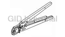
Tool For RF Connectors 1055442-1
Tool For RF Connectors 1055443-1
Insertion Tool For RF Connectors 1055447-1
Insertion Tool For RF Connectors 1055448-1
Assembly Tools, Sma Right Angle Cable Plugs 1055451-1
Request a Quote

The quote request has been received
Close

Facing challenges or have inquiries? Feel free to contact us!
Call Us +1-469-283-2440
What they say about us
FANTASTIC RESOURCE
One of our top priorities is maintaining our business with precision, and we are constantly looking for affiliates that can help us achieve our goal. With the aid of GID Industrial, our obsolete product management has never been more efficient. They have been a great resource to our company, and have quickly become a go-to supplier on our list!
Bucher Emhart Glass
EXCELLENT SERVICE
With our strict fundamentals and high expectations, we were surprised when we came across GID Industrial and their competitive pricing. When we approached them with our issue, they were incredibly confident in being able to provide us with a seamless solution at the best price for us. GID Industrial quickly understood our needs and provided us with excellent service, as well as fully tested product to ensure what we received would be the right fit for our company.
Fuji
HARD TO FIND A BETTER PROVIDER
Our company provides services to aid in the manufacture of technological products, such as semiconductors and flat panel displays, and often searching for distributors of obsolete product we require can waste time and money. Finding GID Industrial proved to be a great asset to our company, with cost effective solutions and superior knowledge on all of their materials, it’d be hard to find a better provider of obsolete or hard to find products.
Applied Materials
CONSISTENTLY DELIVERS QUALITY SOLUTIONS
Over the years, the equipment used in our company becomes discontinued, but they’re still of great use to us and our customers. Once these products are no longer available through the manufacturer, finding a reliable, quick supplier is a necessity, and luckily for us, GID Industrial has provided the most trustworthy, quality solutions to our obsolete component needs.
Nidec Vamco
TERRIFIC RESOURCE
This company has been a terrific help to us (I work for Trican Well Service) in sourcing the Micron Ram Memory we needed for our Siemens computers. Great service! And great pricing! I know when the product is shipping and when it will arrive, all the way through the ordering process.
Trican Well Service
GO TO SOURCE
When I can't find an obsolete part, I first call GID and they'll come up with my parts every time. Great customer service and follow up as well. Scott emails me from time to time to touch base and see if we're having trouble finding something.....which is often with our 25 yr old equipment.
ConAgra Foods