

 Manufacturers
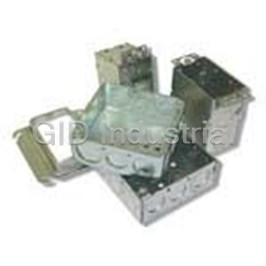
THOMAS & BETTS 171MS13
Description
Raised 4 SQ Steel Box Cover
171MS13
Part Number
171MS13
Price
Request Quote
Manufacturer
THOMAS & BETTS
Lead Time
Request Quote
Category
Thermal Management » Misc Products
Specifications
Manufacturer
Thomas & Betts
Manufacturers Part #
171MS13
Sub-Categories
Miscellaneous Tools and Supplies
Factory Pack Quantity
25
Datasheet

Extracted Text
Metallic Boxes and Covers In This Section… ® Steel City Metallic Boxes and Covers Overview.........................................................................A-2–A-5 Pre-Fab Components and Assemblies ...........................A-6–A-17 Switch Boxes and Accessories ....................................A-18–A-27 Thru-Wall Box.......................................................................A-26 Round Boxes and Accessories...............................................A-28 Octagon Boxes and Accessories..................................A-28–A-32 Ceiling Fan Boxes and Accessories..............................A-33–A-34 Square Boxes and Accessories....................................A-35–A-47 Utility Boxes and Accessories ......................................A-48–A-50 Gang Boxes and Accessories.......................................A-51–A-52 Covers, Concrete Boxes and Accessories.....................A-53–A-54 Concrete/Masonry Boxes and Accessories...................A-54–A-56 Box Hangers and Supports .........................................A-57–A-59 Stud Wall and Drywall Accessories..............................A-60–A-66 A-1 Overview ® Steel City Metallic Boxes & Covers ® Steel City is the industry leading product line of metallic switch and ® outlet boxes used in electrical construction. Since 1904, Steel City products have symbolized the highest quality standards in manufacturing and innovative design, with one of the most complete offerings available. ® Steel City products are known for their simple improve ments, such as being the first box offering to standardize combination slotted/phillips screws on all boxes. Thomas & Betts is also recognized as a leader in design innovation, as in our new metal stud bracket. Thomas & Betts continues to listen to contractors and responds to their ever-changing needs. Contact a T&B distributor nearest ® you to select the right Steel City product for your requirements. ® Advantages of Steel City Boxes & Covers Notched Ears on Raised Ground Screw Bump 11 Switch Boxes in 4" Square, 4 ⁄16" and Utility Boxes ® • Steel City Switch Boxes feature a longer ear and a special notch. • Quicker surface mounting by This provides clearance for the eliminating the need to remove the screws that are used to attach portion of the screw that threads wall plates to GFCI or rocker-type through the back of the box light switches • Allows for improved repositioning of grounding conductor MS Bracket Boxes 1 • Ground bump standard in 2 ⁄8" boxes • Mounts without the use of screws 1 • Ground bump optional in 1 ⁄2" boxes • Mounts to the open or closed side of the stud • Works on stud depths up to 4" Pre-Installed Screws are Packaged in Raised Position Eccentric Knockouts • Eliminates extra step of having on Square Boxes to back out the screw during cover installation • Provide better contact with conduit fitting and locknut to the box, improve grounding path, 3 stronger than ⁄4" knockout ® Steel City switch and outlet boxes are protected from rust and corrosion by • Available in all four standard size zinc-galvanizing. All clamps and other component parts are electrogalvanized square boxes separately, before assembly in the box, to ensure corrosion protection ® of every surface. Steel City galvanized finish meets the requirements 3 • Improved ⁄4" knockout position on square boxes of Underwriters Laboratories, Inc. and Federal Specifications. 3 • Less labor required to install ⁄4" conduit to box A-2 Metallic Boxes and Covers Metallic Boxes and Covers Overview ® Guide to Steel City Knockouts, Pryouts, Ears, Brackets and Clamps Knockouts and Pryouts Knockouts ® Steel City conduit KOs have standard trade size dimensions. KOs are uniform and true 3 1 ⁄8" 3 7 1 ⁄32" for attachment of cable or conduit connectors. Pryouts for cable entrance are slotted ⁄8" — a twist with a screwdriver removes them. KOs and Pryouts are precision stamped 1 3 to permit easy removal, but remain sufficiently strong and sturdy when not removed. ⁄2" Conduit KO 1" Conduit KO ⁄4" Conduit KO Outlet Box Ears Mounting ears support the box independent of the electrical system Eccentric Knockouts Pryouts attachments. Switch boxes have a fixed ear for old work installations. 1 Ears for plaster are set ⁄16" forward of the box face in position for old work (modernization), except where specifically noted. 21 ⁄32" Tapped Holes for Grounding ® All Steel City boxes have a 10-32 tapped hole in the bottom 1 Combination ⁄2" Cable Pryouts always in Pairs. of the box for attaching separate ground wire. 3 & ⁄4" Knockout Brackets CV Type (Outlet Boxes) Mounts to flat side of metal studs or wood studs. 3 SV Type S or B Type T Type 7 ⁄8" long x 1" wide 3 x ⁄8" offset Mounts to face of stud. Used on Positions handy box against Mounts box to side of stud with positioning spikes. switch, handy or square boxes. the face and side of stud. 1 3 3 1 7 2" long x 2 ⁄8" wide 5 ⁄2" long x ⁄8" wide 7 ⁄8" long x 1" wide x ⁄8" offset DV Type MS Type (For Metal Studs) L Type V Type 1 Mounts box offset from stud 1 ⁄2". Mounts to any depth of metal Used to mount octagon boxes. Mounts to flat side of stud. 13 1 5 5 1 3 3 6 ⁄16" long x 1" wide x 1 ⁄2" offset stud, open or closed side. 2 ⁄8" long x 3 ⁄8" wide x ⁄4" offset 7 ⁄8" long x 1" wide x ⁄8" offset 1 11 3 2 ⁄2" long x 1 ⁄16" wide x ⁄8" offset Far side support to 4" only Clamps For Non-Metallic Sheathed Cable and Non-Metallic Tubing (Loom) UNDERWRITERS LABORATORIES INC. and CANADIAN STANDARDS ASSOCIATION file numbers for individual items available upon request. “Products listed in this catalog are subject to alteration or discontinuation without prior notice.” C-1 C-5 Listing Information for Armored Cable Clamp — Type C-3 For Armored ™ MCAP — Aluminum* .370–.580 Cable Armored Cable (BX) — Steel Sizes 14-2 through 10-3 C-8 1 Armored Cable (BX) — Aluminum Sizes 14-2 through 10-3 Flex Metal Conduit — Steel ⁄8" Trade Size 3 (Loom only) Flex Metal Conduit — Aluminum ⁄8" Trade Size MC Interlocked (MCI) — Steel .449–.570 Diameter MC Interlocked (MCI) — Aluminum .476–.606 Diameter C-3 Clamp Acceptable for Grounding MC Corrugated (MCC) — Aluminum .375–.515 Diameter C-3 ™ C-10 * MCAP is a trademark of Southwire Company A-3 Overview ® NEC Reference ® Article 314 of the National Electrical Code covers the installation and use of boxes. The article includes table references that guide the electrician in the selection of the proper box size necessary to safely accommodate electrical service requirements. The box capacity table ® shown (right) is reproduced in part from the NEC as a quick reference ® and guide. The NEC should be consulted for complete details. Article 314 — Boxes and Fittings 314.16. Number of Conductors in Outlet, Device and Junction Boxes and Conduit Bodies. Boxes shall be of sufficient size to provide free space for all conductors enclosed in the box. The provisions of this section shall not apply to terminal housings supplied (b) Other Boxes. with motors or generators. (See Section 430.12.) Boxes 100 cubic inches or less, other than those described in Table Boxes and conduit bodies containing conductors, size No. 4 or larger, 314.16(A), conduit bodies having provisions for more than two conduit shall also comply with the provisions of Section 314.28. entries and non-metallic boxes shall be durably and legibly marked by the manufacturer with their cubic inch capacity. The maximum number (a) Standard Boxes. of conductors permitted shall be computed using the volume per conductor listed in Table 314.16(A), with the deductions provided for in Section The maximum number of conductors permitted in standard boxes are listed 314.16(B), and these volume deductions shall be based on the largest in Table 314.16(A) reproduced in part on page A6. See Article 314.28(A) conductor entering the box. Boxes described in Table 314.16(A) that have a through (D) where boxes or conduit bodies are used as junction or pull boxes. larger cubic inch capacity than is designated in the table shall be permitted (1) Table 314.16(A) shall apply where no fittings or devices, such as fixture to have their cubic inch capacity marked as required by this section and studs, cable clamps, hickeys, switches, or receptacles, are contained in the maximum number of conductors permitted shall be computed using the box and where no grounding conductors are part of the wiring within the volume per conductor listed in Table 314.16(B). the box. Where one or more of these types of fittings, such as fixture studs, cable clamps, or hickeys are contained in the box, the number of conductors shown in the table must be reduced by one for each type of (c) Conduit Bodies. fitting; an additional deduction of one conductor must be made for each Conduit bodies enclosing 6AWG conductors or smaller other than short- strap containing one or more devices; and a further deduction of one radius conduit bodies as described in 314.5, shall have a cross-sectional conductor shall be made for one or more grounding conductors entering the box. Where a second set of equipment grounding conductors, as area not less than twice the cross-sectional area of the largest conduit to permitted by Section 250.146(D), is present in the box, then an additional which they can be attached. The maximum number of conductors permitted deduction of one conductor must be made. A conductor running through shall be the maximum number permitted by Table I, Chapter 9, for the the box is counted as one conductor, and each conductor originating conduit to which it is attached. outside of the box and terminating inside the box is counted as one Conduit bodies that are durably and legibly marked by a manufacturer conductor. Conductors, no part of which leaves the box, shall not be counted. The volume of a wiring enclosure (box) shall be the total volume with their volume shall be permitted to contain splices, taps or devices. of the assembled sections, and, where used, the space provided by The maximum number of conductors shall be calculated in accordance plaster rings, domed covers, extension rings, etc., that are marked with with 314.16(B) and are supported in a rigid and secure manner. their volume in cubic inches, or are made from boxes the dimensions of which are listed in Table 314.16(A). (2) For combinations of conductor sizes shown in Table 314.16(A), the maximum number of conductors permitted is computed using the volume per conductor listed in Table 314.16(B) with the deductions provided for in Section 314.16(B) and these volume deductions shall be based on the largest conductor entering the box. The maximum number and size of conductors listed in Table 314.16(A) must not be exceeded. A-4 Metallic Boxes and Covers Metallic Boxes and Covers Overview Article 314 — Boxes and Fittings (continued) Table 314.16(A) Table 314.16(B) Metal Boxes Volume Allowance Required per Conductor MINIMUM MAXIMUM NUMBER SIZE OF CONDUCTOR FREE SPACE WITHIN BOX FOR EACH CONDUCTOR 3 3 BOX TRADE SIZE VOLUME OF CONDUCTORS* (AWG) CM IN. MM (IN.) CM3 IN.3 18 16 14 12 10 8 6 No. 18 24.6 1.50 1 100 x 32 (4 x 1 ⁄4) Round/Octagonal 205 12.5 8 7 6 5 5 5 2 No. 16 28.7 1.75 1 100 x 38 (4 x 1 ⁄2) Round/Octagonal 254 15.5 10 8 7 6 6 5 3 No. 14 32.8 2.00 1 100 x 54 (4 x 2 ⁄8) Round/Octagonal 353 21.5 14 12 10 9 8 7 4 No. 12 36.9 2.25 1 100 x 32 (4 x 1 ⁄4) Square 295 18.0 12 10 9 8 7 6 3 No. 10 41.0 2.50 1 100 x 38 (4 x 1 ⁄2) Square 344 21.0 14 12 10 9 8 7 4 No. 8 49.2 3.00 1 100 x 54 (4 x 2 ⁄8) Square 497 30.3 20 17 15 13 12 10 6 No. 6 81.9 5.00 1 120 x 32 (4L x 1 ⁄4) Square 418 25.5 17 14 12 11 19 8 5 Reprinted with permission from National Fire Protection Association 70-1987. National 1 120 x 38 (4L x 1 ⁄2) Square 484 29.5 19 16 14 13 11 9 5 Electrical Code, Copyright© 1986, National Fire Protection Association, Quincy, MA 02269. 1 This reprinted material is not the complete and official position of the NFPA on the 120 x 54 (4L x 2 ⁄8) Square 689 42.0 28 24 21 18 16 14 8 referenced subject which is represented only by the standard in its entirety. 1 75 x 50 x 38 (3 x 2 x 1 ⁄2) Device 123 7.5 5 4 3 3 3 2 1 ® NEC is a registered trademark of the National Fire Protection Association, Inc., 75 x 50 x 50 (3 x 2 x 2) Device 164 10.0 6 5 5 4 4 3 2 Quincy, MA 02269. 1 75 x 50 x 57 (3 x 2 x 2 ⁄4) Device 172 10.5 7 6 5 4 4 3 2 Underwriters Laboratories Inc. File Number: E2969 (U.L. 514A) 1 75 x 50 x 65 (3 x 2 x 2 ⁄2) Device 205 12.5 8 7 6 5 5 4 2 Canadian Standards Association File Number: LR 12798 3 75 x 50 x 70 (3 x 2 x 2 ⁄4) Device 230 14.0 9 8 7 6 5 4 2 Federal Manufacture Number: 56501 1 75 x 50 x 90 (3 x 2 x 3 ⁄2) Device 295 18.0 12 10 9 8 7 6 3 Products designed to meet Federal Specification Number: A-A5924 (formerly W-J-800). 1 1 100 x 54 x 38 (4 x 2 ⁄8 x 1 ⁄2) Device 169 10.3 6 5 5 4 4 3 2 Verification of file numbers and compliance with federal specifications for individual items 1 7 100 x 54 x 48 (4 x 2 ⁄8 x 1 ⁄8) Device 213 13.0 8 7 6 5 5 4 2 available upon request. 1 1 100 x 54 x 54 (4 x 2 ⁄8 x 2 ⁄8) Device 238 14.5 9 8 7 6 5 4 2 Box and cover material and plating specification; .062" minimum thickness, 3 1 95 x 50 x 65 (3 ⁄4 x 2 x 2 ⁄2) Masonry Box/Gang 230 14.0 9 8 7 6 5 4 2 hot rolled, pre-galvanized steel, minimum spangle. 3 1 95 x 50 x 90 (3 ⁄4 x 2 x 3 ⁄2) Masonry Box/Gang 244 21.0 14 12 10 9 8 7 2 ASTM G-60-U, AISI C-1008 3 Min. 44.5 depth FS – Single-Cover/Gang (1 ⁄4) 221 13.5 9 7 6 6 5 4 2 Bracket material: All brackets except MS style; 16 gauge (.060") hot rolled, pre-galvanized 3 Min. 60.3 depth FD – Single-Cover/Gang (2 ⁄8) 295 18.0 12 10 9 8 7 6 3 steel AISI C-1008, G-60-U. MS Style bracket; 20 gauge (.036") cold rolled spring steel AISI 3 C-1055, heat treated to R. 35 zinc plated .0005 thick. Min. 44.5 depth FS – Multiple-Cover/Gang (1 ⁄4) 295 18.0 12 10 9 8 7 6 3 3 Min. 60.3 depth FD – Multiple-Cover/Gang (2 ⁄8) 395 24.0 16 13 12 10 9 8 4 *Where no volume allowances are required by 314.16(B)(2) through 314.16(B)(5). Metallic Boxes — Fire Resistance Rating Underwriters Laboratories Inc. File Number: E2969 (U.L. 514A) Canadian Standards Association File Number: LR 12798 Wall Penetrations Federal Manufacture Number: 56501 (Cage Code) Listed single- and double-gang metallic outlet and switch boxes and Products designed to meet Federal Specification Number: W-J-800 octagon ceiling boxes with metallic or non-metallic cover plates may Verification of file numbers and compliance with federal specifications for individual items be used in bearing and non-bearing wood stud and steel stud walls available upon request. with ratings not exceeding 2 hours. These walls shall have gypsum Box and cover material and plating specification; .062" minimum thickness, hot rolled, wallboard facings similar to those shown in Design Nos. U301, U411, pre-galvanized steel, minimum spangle. and U425. 4 in. square boxes may be used in 2 hr. fire rated ceilings. ASTM G-60-U, AISI C-1008 The surface area of individual metallic outlet or switch boxes shall not Bracket material: All brackets except MS style; 16 gauge (.060") hot rolled, pre-galvanized steel AISI C-1008, G-90-U. MS style bracket; 20 gauge (.036") cold rolled spring steel AISI exceed 16 sq. in. The aggregate surface area of the boxes shall not exceed C-1055, heat treated to R. 35 zinc plated .0005 thick. 100 sq. inches per 100 sq. ft. of wall. Boxes located on opposite sides of walls or partitions shall be separated by a horizontal distance of 24 inches. The metallic outlet or switch boxes shall be securely fastened to the studs and the opening in the wallboard facing shall be cut so that the clearance 1 between the box and the wallboard does not exceed ⁄8 in. A-5 Pre-Fab Components and Assemblies Faster Installation for Increased Profit Margin! Pre-Assemblies Paying to assemble outlet boxes, grounding pigtails, device covers and mounting brackets on the job site can quickly become an expensive proposition. Instead, ® choose Steel City Pre-Assemblies and realize significant labor Box with Pre-Installed 1 savings. This UL Listed 10 ⁄2" Pigtail product line includes over 75 • Popular 4" square boxes and combinations of popular boxes, switch boxes brackets and covers that speed 1 • Pre-installed 10 ⁄2" insulated installation because the time- grounding pigtails consuming assembly work is already done for you. • Save on labor costs by eliminating multiple installation steps ® Steel City Pre-Assemblies include: • Outlet box with pre-installed grounding pigtail • Your choice of cover options, including single- Pre-Assembled Installation Standard Installation vs. and double-device covers, 1 5 3 raised ⁄2", ⁄8" or ⁄4" 1 Purchase pre-stripped pigtail Install box 1 • Your choice of bracket options in desired to allow mounting to steel 2 Install pigtail and ground screw in box location — and wood stud or floor track, ® including Steel City Box DONE! 3 Install box in desired location Support Covers, which combine a bracket and cover in one component • All UL Listed components BOX TYPE PRE-INSTALLED STD. CAT. NO. INCLUDED KNOCKOUTS PIGTAIL CTN. 1 1 521511234EWP 52151234EW — 4"-sq. x 1 ⁄2"D Welded Box Eccentric 10 ⁄2"50 1 1 3 1 521511234P 521511234 — 4"-sq. x 1 ⁄2"D Drawn Box ⁄2" & ⁄4"10 ⁄2"50 1 1 3 1 521711234EP 521711234E — 4"-sq. x 2 ⁄8"D Welded Box ⁄2" & ⁄4" Eccentric 10 ⁄2"50 1 1 3 1 52151XP 52151X — 4"-sq. x 1 ⁄2"D Welded Box ⁄2" & ⁄4" Eccentric 10 ⁄2"50 1 1 3 1 52151CVNP 52151CVN — 4"-sq. x 1 ⁄2"D Welded Box ⁄2" & ⁄4" Eccentric 10 ⁄2"25 1 1 1 LXWOWP LXWOW-25 — 3"H x 2"W x 2 ⁄2"D Gangable Switch Box ⁄2"10 ⁄2"25 1 1 1 LXVP LXV-25 — 3"H x 2"W x 2 ⁄2"D Gangable Switch Box ⁄2"10 ⁄2"25 1 1 3 1 CXWOWP CXWOW — 3"H x 2"W x 3 ⁄2"D Gangable Switch Box ⁄2" & ⁄4"10 ⁄2"25 1 1 3 1 CXWVP CXWV — 3"H x 2"W x 3 ⁄2"D Gangable Switch Box ⁄2" & ⁄4"10 ⁄2"25 1 1 3 1 CXP CX — 3"H x 2"W x 3 ⁄2"D Gangable Switch Box ⁄2" & ⁄4"10 ⁄2"25 A-6 Metallic Boxes and Covers Metallic Boxes and Covers Pre-Fab Components and Assemblies 1 Box with Pre-Installed 10 ⁄2" Pigtail and Box Support Cover 1 5 • 52CM and 52CMD box • Raised ⁄2", ⁄8" 3 support covers and ⁄4" 1 1 1 • 10 ⁄2" insulated pigtail • 1 ⁄2" and 2 ⁄8" box depths • One- and two-device covers 52171-CM14-5/8 BOX BOX PIGTAIL BOX SUPPORT TYPE DEPTH TYPE COVER RAISEDNO. OF STD. CAT. NO. INCLUDED (IN.) INCLUDED INCLUDED (IN.) DEVICES CTN. 1 1 52151-CM13 521511234EW 1 ⁄2 GSC12 52CM13 ⁄2 125 1 5 52151-CM14-5/8 521511234EW 1 ⁄2 GSC12 52CM14-5/8 ⁄8 125 1 3 52151-CM14 521511234EW 1 ⁄2 GSC12 52CM14 ⁄4 125 1 1 52151-CMD17 521511234EW 1 ⁄2 GSC12 52CMD17 ⁄2 225 1 5 52151-CMD18-5/8 521511234EW 1 ⁄2 GSC12 52CMD18-5/8 ⁄8 225 1 3 52151-CMD18 521511234EW 1 ⁄2 GSC12 52CMD18 ⁄4 225 1 1 52171-CM13 521711234E 2 ⁄8 GSC12 52CM13 ⁄2 125 1 5 52171-CM14-5/8 521711234E 2 ⁄8 GSC12 52CM14-5/8 ⁄8 125 1 3 52171-CM14 521711234E 2 ⁄8 GSC12 52CM14 ⁄4 125 1 1 52171-CMD17 521711234E 2 ⁄8 GSC12 52CMD17 ⁄2 225 1 5 52171-CMD18-5/8 521711234E 2 ⁄8 GSC12 52CMD18-5/8 ⁄8 225 1 3 52171-CMD18 521711234E 2 ⁄8 GSC12 52CMD18 ⁄4 225 Box with Pre-Installed 1 10 ⁄2" Pigtail, Raised Cover and Box-to-Stud Bracket 1 5 • SSF-SH2346 bracket • Raised ⁄2", ⁄8" 3 and ⁄4" 1 • 10 ⁄2" insulated pigtail 1 1 • 1 ⁄2" and 2 ⁄8" 151-SH2346-13 • One- and two-device box depths covers 171-SH2346-17 BOX BOX PIGTAIL BRACKET COVER TYPE DEPTH TYPE TYPE TYPE RAISED NO. OF STD. CAT. NO. INCLUDED (IN.) INCLUDED INCLUDED INCLUDED (IN.) DEVICES CTN. 1 1 151-SH2346-13 521511234EW 1 ⁄2 GSC12 SSF-SH2346 52-C-13 ⁄2 110 1 5 151-SH2346-1458 521511234EW 1 ⁄2 GSC12 SSF-SH2346 52-C-14-5/8 ⁄8 110 1 3 151-SH2346-14 521511234EW 1 ⁄2 GSC12 SSF-SH2346 52-C-14 ⁄4 110 1 1 151-SH2346-17 521511234EW 1 ⁄2 GSC12 SSF-SH2346 52-C-17-25 ⁄2 210 1 5 151-SH2346-1858 521511234EW 1 ⁄2 GSC12 SSF-SH2346 52-C-18-5/8-25 ⁄8 210 1 3 151-SH2346-18 521511234EW 1 ⁄2 GSC12 SSF-SH2346 52-C-18 ⁄4 210 1 1 171-SH2346-13 521711234E 2 ⁄8 GSC12 SSF-SH2346 52-C-13 ⁄2 110 1 5 171-SH2346-1458 521711234E 2 ⁄8 GSC12 SSF-SH2346 52-C-14-5/8 ⁄8 110 1 3 171-SH2346-14 521711234E 2 ⁄8 GSC12 SSF-SH2346 52-C-14 ⁄4 110 1 1 171-SH2346-17 521711234E 2 ⁄8 GSC12 SSF-SH2346 52-C-17-25 ⁄2 210 1 5 171-SH2346-1858 521711234E 2 ⁄8 GSC12 SSF-SH2346 52-C-18-5/8-25 ⁄8 210 1 3 171-SH2346-18 521711234E 2 ⁄8 GSC12 SSF-SH2346 52-C-18 ⁄4 210 A-7 Pre-Fab Components and Assemblies MS Series Pre-Assemblies 11 • 4" square and 4 ⁄16" square boxes 1 1 • 1 ⁄2" deep or 2 ⁄8" deep 1 • Pre-installed 10 ⁄2" insulated grounding pigtail • Available with conduit KOs or clamps for flexible/armored/MC cable • Save on labor costs by eliminating multiple installation steps Pre-Assembled Installation Standard Installation vs. Purchase pre-stripped pigtail 1 1 Snap box — DONE! 2 Install pigtail and ground screw in box 3 Mount box support cover to box 4 Mount assembly to stud BOX TYPE BOX PIGTAIL BOX COVER RAISED NO. OF STD. CAT. NO. INCLUDED DEPTH (IN.) INCLUDED (IN.) INCLUDED (IN.) DEVICES CTN. 1 1 1 151-MS-13 52151-MS-1/2 3/4 1 ⁄2 10 ⁄2 52-C-13 ⁄2 125 1 1 3 151-MS-14 52151-MS-1/2 3/4 1 ⁄2 10 ⁄2 52-C-14 ⁄4 125 1 1 5 151-MS-1458 52151-MS-1/2 3/4 1 ⁄2 10 ⁄2 52-C-14-5/8 ⁄8 125 1 1 1 171MS13 52171-MS-1/2 3/4 2 ⁄8 10 ⁄2 52-C-13 ⁄2 125 1 1 3 171-MS-14 52171-MS-1/2 3/4 2 ⁄8 10 ⁄2 52-C-14 ⁄4 125 1 1 5 171-MS-1458 52171-MS-1/2 3/4 2 ⁄8 10 ⁄2 52-C-14-5/8 ⁄8 125 1 1 3 171MS18 52171-MS-1/2 3/4 2 ⁄8 10 ⁄2 52-C-18 ⁄4 225 1 1 5 171-MS-18 5/8 52171-MS-1/2 3/4 2 ⁄8 10 ⁄2 52-C-18-5/8-25 ⁄8 225 1 1 1 171MSX13 52171-MSX 2 ⁄8 10 ⁄2 52-C-13 ⁄2 125 1 1 3 171-MSX-14 52171-MSX 2 ⁄8 10 ⁄2 52-C-14 ⁄4 125 1 1 5 171-MSX-1458 52171-MSX 2 ⁄8 10 ⁄2 52-C-14-5/8 ⁄8 125 1 1 3 171MSX18 52171-MSX 2 ⁄8 10 ⁄2 52-C-18 ⁄4 225 1 1 5 171-MSX-18 5/8 52171-MSX 2 ⁄8 10 ⁄2 52-C-18-5/8-25 ⁄8 225 1 1 3 72171MS14 72171-MS-1/2 3/4 2 ⁄8 10 ⁄2 72-C-14 ⁄4 125 1 1 5 72171-MS-1458 72171-MS-1/2 3/4 2 ⁄8 10 ⁄2 72-C-14-5/8 ⁄8 125 1 1 3 72171MS18 72171-MS-1/2 3/4 2 ⁄8 10 ⁄2 72-C-18 ⁄4 225 1 1 5 72171-MS-18 5/8 72171-MS-1/2 3/4 2 ⁄8 10 ⁄2 72-C-18-5/8 ⁄8 225 1 1 3 72171MSX14 72171-MS-1/2 3/4 2 ⁄8 10 ⁄2 72-C-14 ⁄4 125 1 1 5 72171-MSX-1458 72171-MSX 2 ⁄8 10 ⁄2 72-C-14-5/8 ⁄8 125 1 1 3 72171MSX18 72171-MS-1/2 3/4 2 ⁄8 10 ⁄2 72-C-18 ⁄4 225 1 1 5 72171-MSX-1858 72171-MS-1/2 3/4 2 ⁄8 10 ⁄2 72-C-18-5/8 ⁄8 225 A-8 Metallic Boxes and Covers Metallic Boxes and Covers Pre-Fab Components and Assemblies 1 Box with Pre-Installed 10 ⁄2" Pigtail, Raised Cover and Vertical Mounting Bracket • 12" (SSF-SV12) or 18" (SSF-SV18) vertical mounting bracket 1 • 10 ⁄2" insulated pigtail • One- and two-device covers 1 5 3 • Raised ⁄2", ⁄8" and ⁄4" 1 1 • 1 ⁄2" and 2 ⁄8" box depths Pre-Assembled Installation Standard Installation vs. 1 Purchase pre-stripped pigtail Mount 1 assembly to 2 Install pigtail and ground screw in box floor stud — DONE! 3 Insert box into vertical bracket 4 Insert device cover to vertical bracket Mount assembly to floor stud 5 151-SV12-13 151-SV18-13 BOX BOX PIGTAIL BRACKET COVER TYPE DEPTH TYPE TYPE TYPE RAISED NO. OF STD. CAT. NO. INCLUDED (IN.) INCLUDED INCLUDED INCLUDED (IN.) DEVICES CTN. 1 1 151-SV12-13 521511234EW 1 ⁄2 GSC12 SSF-SV12 52-C-13 ⁄2 110 1 5 151-SV12-1458 521511234EW 1 ⁄2 GSC12 SSF-SV12 52-C-14-5/8 ⁄8 110 1 3 151-SV12-14 521511234EW 1 ⁄2 GSC12 SSF-SV12 52-C-14 ⁄4 110 1 1 151-SV12-17 521511234EW 1 ⁄2 GSC12 SSF-SV12 52-C-17-25 ⁄2 210 1 5 151-SV12-1858 521511234EW 1 ⁄2 GSC12 SSF-SV12 52-C-18-5/8-25 ⁄8 210 1 3 151-SV12-18 521511234EW 1 ⁄2 GSC12 SSF-SV12 52-C-18 ⁄4 210 1 1 171-SV12-13 521711234E 2 ⁄8 GSC12 SSF-SV12 52-C-13 ⁄2 110 1 5 171-SV12-1458 521711234E 2 ⁄8 GSC12 SSF-SV12 52-C-14-5/8 ⁄8 110 1 3 171-SV12-14 521711234E 2 ⁄8 GSC12 SSF-SV12 52-C-14 ⁄4 110 1 1 171-SV12-17 521711234E 2 ⁄8 GSC12 SSF-SV12 52-C-17-25 ⁄2 210 1 5 171-SV12-1858 521711234E 2 ⁄8 GSC12 SSF-SV12 52-C-18-5/8-25 ⁄8 210 1 3 171-SV12-18 521711234E 2 ⁄8 GSC12 SSF-SV12 52-C-18 ⁄4 210 1 1 151-SV18-13 521511234EW 1 ⁄2 GSC12 SSF-SV18 52-C-13 ⁄2 110 1 5 151-SV18-1458 521511234EW 1 ⁄2 GSC12 SSF-SV18 52-C-14-5/8 ⁄8 110 1 3 151-SV18-14 521511234EW 1 ⁄2 GSC12 SSF-SV18 52-C-14 ⁄4 110 1 1 151-SV18-17 521511234EW 1 ⁄2 GSC12 SSF-SV18 52-C-17-25 ⁄2 210 1 5 151-SV18-1858 521511234EW 1 ⁄2 GSC12 SSF-SV18 52-C-18-5/8-25 ⁄8 210 1 3 151-SV18-18 521511234EW 1 ⁄2 GSC12 SSF-SV18 52-C-18 ⁄4 210 1 1 171-SV18-13 521711234E 2 ⁄8 GSC12 SSF-SV18 52-C-13 ⁄2 110 1 5 171-SV18-1458 521711234E 2 ⁄8 GSC12 SSF-SV18 52-C-14-5/8 ⁄8 110 1 3 171-SV18-14 521711234E 2 ⁄8 GSC12 SSF-SV18 52-C-14 ⁄4 110 1 1 171-SV18-17 521711234E 2 ⁄8 GSC12 SSF-SV18 52-C-17-25 ⁄2 210 1 5 171-SV18-1858 521711234E 2 ⁄8 GSC12 SSF-SV18 52-C-18-5/8-25 ⁄8 210 1 3 171-SV18-18 521711234E 2 ⁄8 GSC12 SSF-SV18 52-C-18 ⁄4 210 A-9 Pre-Fab Components and Assemblies UL Listed Adjustable Mud Ring now available in both single- and two-gang. Adjustable Mud Rings 1 1 Mud Rings feature an inner ring that adjusts from ⁄2" to 1 ⁄2" in depth to accommodate various drywall thicknesses. Marked with a measured rule and equipped with two adjustment screws, the inner ring can be set to the anticipated depth prior to installation and then easily adjusted after drywall 1 1 installation to accommodate any variation in depth ( ⁄2" to 1 ⁄2"). Wedge Locking Blocks Designed to ensure grounding continuity Adjustable Mud Ring Installation/Adjustment Steps: 1 3 2 Loosen… Adjust… Re-tighten… The two adjustment screws located on opposing corners Inner ring to be flush with wall surface. Adjustment screws. of the mud ring. Adjustable Mud Ring CAT. N0. DESCRIPTION STD. CTN. 1 1 52-C-ADJ Single-Gang Adjustable Mud Ring, ⁄2" to 1 ⁄2"25 1 1 52-C-ADJ2 Two-Gang Adjustable Mud Ring, ⁄2" to 1 ⁄2"20 A-10 Metallic Boxes and Covers Metallic Boxes and Covers Pre-Fab Components and Assemblies Consistent Box Locations and Box Height…Every Time! Pre-Fab T Bracket Stability Ridges Consistency results in efficiency and labor savings on the job. With three For added support. ® fixed-box locations and a fixed height of 18", the new Steel City Pre-Fab T Bracket provides a consistent installation every time. For added efficiency, the bracket includes integral mounting screws that help reduce installation time. A handy locator tab at the base of the bracket saves you the time of looking for installed boxes that have been hidden by wall coverings. The base also features unique floor track tabs. The inner tab slides in front of the floor track and the two outer tabs slide behind the floor track to provide stability when positioning the bracket. Floor Track Tabs Provide stability when positioning the bracket. Locator Tab Helps locate installed boxes hidden by wall coverings. 3 Fixed-Box Locations Each accommodate both 11 4" & 4 ⁄16" boxes. Integral Mounting Screws 18" Fixed Height Reduce installation time. 16" Fixed Width Key Hole Slots Mud Ring Mounting Screw Holes Maintain box position For low-voltage applications if mud ring is removed. where no box is required. Pre-Fab Box Bracket with Far-Side and Cable Support CAT. N0. DESCRIPTION STD. CTN. H16V18S Pre-Fab T Bracket 10 A-11 Pre-Fab Components and Assemblies SBO16 and SBO24 Easily Stud-to-Stud Horizontal Pre-Assembled Mounting Brackets Off Site • Constructed of 24-gauge steel for Faster • Pre-measured on center for 16" (SBO16) or 24" (SBO24) stud spacing 11 • SBO16 accepts three 4" square or two 4 ⁄16" boxes (deep or shallow) Installation 11 • SBO24 accepts five 4" square or four 4 ⁄16" boxes (deep or shallow) On Site! • Can be mounted at any height to meet individual project requirements • Versatile, open design enables mounting of box in any location across horizontal plane between studs Pre-Fabricated • Device cover (mud ring) mounts to front of bracket to set box in desired location Components 1 1 • Stamped rule on bracket with ⁄4", ⁄2" and 1" markings enables fast box setting Rather than assembling box mounting brackets and device covers on site, keep an eye on ® profit and use Steel City Pre-Fab Components SBO16 H16S to set up jobs off site for a quick and easy installation on site. They accommodate a wide variety of Steel City covers and they’re SBO24 readily available for fast-track projects. • Ideal for use in hotels, casinos, hospitals, large office buildings and any other commercial or institutional application where SBO16 mounted to 16" studs SBO24 mounted to 24" studs rough-in products with one 4" square box installed. with one 4" square box installed. can be pre-fabricated to match floor plans for quicker on-site installation • Items readily available for fast-track projects — no special lead time required SBO16 mounted to 16" studs with three SBO24 mounted to 24" studs with five 4" square boxes (full capacity) installed. 4" square boxes (full capacity) installed. • All products are UL approved and meet Stud-to-Stud Horizontal Mounting Brackets applicable building codes CAT. NO. DESCRIPTION STD. CTN. SBO16 16" stud-to-stud horizontal mounting bracket 25 SBO24 24" stud-to-stud horizontal mounting bracket 25 A-12 Metallic Boxes and Covers Metallic Boxes and Covers Pre-Fab Components and Assemblies SV1218 Floor-Track 12" and 18" Vertical Mounting Bracket • Code-standard SV1218 bracket mounts to floor track easily • Support bar pre-measured for 24" stud cavities (score lines provided with screws through three pre-punched holes in bottom plate for 16" stud cavities) with pre-punched holes at stud locations for (only two screws required for most applications) left or right stud installation • Offers pre-measured box-mount locations at 12" and 18" from • Add optional SVX adapter plate to expand box capacity floor — fast installation with no measuring required • Optional SVX adapter plate installs to pre-punched and tapped 11 • Accepts 4" square or 4 ⁄16" boxes (deep or shallow) with standard holes on sides of SV1218 device covers (mud rings) • Up to two SVX plates can be added with 24" stud spacing • Supplied with horizontal cross-support bar for stability after • One SVX plate can be added with 16" stud spacing installation — prevents unit from falling into open space 11 between walls when sheetrock is applied • SVX adapter plate accepts all device covers for 4" and 4 ⁄16" boxes • Support bar sits in two slotted tabs on backside of vertical bracket and mounts from stud to stud horizontally SVX with box installed. SVX SV1218 SV1218 mounted to floor track and studs SV1218 mounted to floor track and studs with one 4" square box installed and optional with one 4" square box installed. SVX adapter plate with one box installed. Floor-Track 12" and 18" Vertical Mounting Bracket CAT. NO. DESCRIPTION STD. CTN. SV1218 Floor-track vertical mounting bracket with supporting horizontal cross bar 10 SVX Adapter plate for expanded capacity for SV1218 25 A-13 Pre-Fab Components and Assemblies VAFB Vertically Adjustable Floor Brackets Built-in Far-Side Support for Both Built-in Slots for 4" and 6" Studs Horizontal Support Bar Stabilizes box and bracket Provides the option to assembly, providing reinforce stud-to-stud versatility on the job strength (horizontal and ease of installation. support bar not included). UL Listed Built-in Cable Support Reduces labor and material costs by Flexible Design eliminating the need Accommodates both to purchase and install 11 4" and 4 ⁄16" boxes. a separate cable support. Standard 12" and 18" Box Mounting Locations Single-Screw Vertical Height Adjustment Up to 6 additional inches. Floor Bracket 6" Height Adjustment CAT. NO. DESCRIPTION STD. CTN. Markings VAFB Pre-Fab Vertically Adjustable Floor Bracket 10 DBB1 Dual-Box Mounting Bracket Locator Hole In mounting bracket enables installer to position box on marked stud for fast, precise installation. Power Left of Power on Both Stud and Low Sides of the Stud Voltage Right of the Stud Accommodates both 4" and Low Voltage Power and Low 11 4 ⁄16" boxes Built-in Far-Side Support on Both Sides Voltage on the Stabilizes box and bracket of the Stud Same Side of assembly to ease installation the Stud and eliminate the need to purchase and install UL Listed extra components. Dual-Box Mounting Bracket CAT. NO. DESCRIPTION STD. CTN. DDB1 Pre-Fab Dual-Box Bracket 50 A-14 Metallic Boxes and Covers Metallic Boxes and Covers Pre-Fab Components and Assemblies Meet Code Requirements for Supporting and Securing Installed MC Cable. Cable Support Bracket ® • Provides a simple means of complying with NEC 348.30 requirements for securing and supporting MC cable • Quick and easy locking tab snaps through slot to secure cable • Ribs maintain separation of cables • Durable steel construction retains integrity • Versatile design — use with Romex or MC cable • UL Listed Cable Support Bracket CAT. N0. DESCRIPTION STD. CTN. CSB1 Cable Support Bracket 100 A-15 Pre-Fab Components and Assemblies Easy to identify and install! Bright Red Fire Alarm Boxes and Fittings Finish ® Steel City Fire Alarm Boxes and Fittings can meet all of your visual identification requirements for fire alarm systems — and make installation and upgrades faster and easier than ever before! Available in a variety of sizes to accommodate new or old work configurations, these boxes are simple to install with high-quality Thomas & Betts fittings. Plus, the bright red finish eliminates time-consuming painting of existing fixtures and provides long-lasting identification in even the harshest environments. 52171-1234RD 72171-1234RD 52171-EXTRD 52-C-1RD 52151-1234RD 52171-CV-1234RD 52171-EXTOWRD 53171-1234RD Fire Alarm Boxes EACH SIDE EACH END BOTTOM CU. IN. STD. CAT. NO. DESCRIPTION EARS BRACKETS CONDUIT CONDUIT CONDUIT CAPACITY CTN. 1 1 1 3 1 1 3 1 1 3 52171-1234RD 2 ⁄8"-deep 4-square red box — — 2 ⁄2", 1 ⁄2" & ⁄4" E 2 ⁄2", 1 ⁄2" & ⁄4"E 3 ⁄2", 2 ⁄2" & ⁄4"E 30.3 50 1 1 3 1 3 1 3 52151-1234RD 1 ⁄2"-deep drawn red box — — 2 ⁄2", 1 ⁄4"2 ⁄2", 1 ⁄4"3 ⁄2", 2 ⁄4" 21.0 50 1 11 1 3 1 3 1 1 3 72171-1234RD 2 ⁄8"-deep 4 ⁄16" red box — — 3 ⁄2" & ⁄4"E 3 ⁄2" & ⁄4"E 3 ⁄2", 2 ⁄2" & ⁄4"E 42.0 20 1 1 1 3 1 1 3 1 1 3 52171-CV-1234RD 2 ⁄8"-deep 4-square red box with CV bracket — CV 2 ⁄2", 1 ⁄2" & ⁄4"E 2 ⁄2", 1 ⁄2" & ⁄4"E 3 ⁄2", 2 ⁄2" & ⁄4"E 30.3 50 1 1 1 3 1 1 3 1 1 3 52171-EXTRD 2 ⁄8"-deep 4-square red box with ext. ring — — 4 ⁄2", 2 ⁄2" & ⁄4"E 4 ⁄2", 2 ⁄2" & ⁄4"E 3 ⁄2", 2 ⁄2" & ⁄4"E 60.6 25 1 1 1 3 1 1 3 1 1 3 52171-EXTOWRD 2 ⁄8"-deep 4-square red box Yes — 4 ⁄2", 2 ⁄2" & ⁄4"E 4 ⁄2", 2 ⁄2" & ⁄4"E 3 ⁄2", 2 ⁄2" & ⁄4"E 60.6 25 with ext. ring and old work ears 52 C 1RD Flat 4-square red cover — — — — — — 100 1 1 1 3 1 1 3 53171-1234RD 2 ⁄8"-deep 4-square red extension ring — — 2 ⁄2", 1 ⁄2" & ⁄4"E 2 ⁄2", 1 ⁄2" & ⁄4"E — 30.3 25 Fire Alarm Fittings CAT. N0. DESCRIPTION STD. CTN. 1 TC121A-FA ⁄2" Red Steel EMT Set Screw Connector 50 3 TC122A-FA ⁄4" Red Steel EMT Set Screw Connector 50 TC123A-FA 1" Red Steel EMT Set Screw Connector 25 1 TC721A-FA ⁄2" Red Insulated Steel EMT Set Screw Connector 50 TK122A-FA TK121A-FA 3 TC722A-FA ⁄4" Red Insulated Steel EMT Set Screw Connector 50 TC723A-FA 1" Red Insulated Steel EMT Set Screw Connector 25 1 TK121A-FA ⁄2" Red Steel EMT Set Screw Coupling 50 3 TK122A-FA ⁄4" Red Steel EMT Set Screw Coupling 50 TC122A-FA TC121A-FA TK123A-FA 1" Red Steel EMT Set Screw Coupling 25 A-16 Metallic Boxes and Covers Metallic Boxes and Covers Pre-Fab Components and Assemblies Easy Depth Adjustment After Wall Covering Installation. ® Adjust-A-Box The Adjust-A-Box System adapts to a variety of wall coverings. Its design enables the installer to adjust the box to various depths with the turn of a screw. Features: Design allows for adjustment of depth after the wall covering has been installed Adjusts to any wall covering MB120ADJ Mounts square and secure every time Removes easily to enable inner-wall access Accommodates high- and low-voltage applications Pre-installed ground screw Pre-Installed Adjustable Screw Ground Screw Allows adjustment to any Accommodates non-metallic cable, wall-covering thickness. flexible metal cable and EMT ½" Knockouts for MC Cable and EMT Clamps for Non-Metallic Cable MB238ADJ Installation: Screw bracket to stud Adjust box in or out to any wall thickness Single-Gang Two-Gang Single-Gang Two-Gang ® ® Steel City Adjust-A-Box VOLUME STD. STD. WT. CAT. NO. (CU. IN.) DESCRIPTION KNOCKOUTS SIZE (IN.) CTN. (LBS.) 1 MB120ADJ 20 One-Gang Adjustable Wall Box ⁄2" (5) 2.20W x 3.28H x 3.52D 18 19.25 1 MB238ADJ 38 Two-Gang Adjustable Wall Box ⁄2" (8) 4.01W x 3.28H x 3.52D 12 17.60 A-17 Switch Boxes and Accessories 3" x 2" Switch Boxes SWB-25 LXMWOW-25 LCOWC LXWOW-25 LXWOWP LXWLE-25 Ears flush Ears flush Adapts to any wall Ears flush 3 for old work for old work thickness up to ⁄4" for old work LXWOWC-25 LXWSV LXWV-25 811-SW-25 LCOW-25 LCLE-25 5 Adapts to any wall SV bracket CV bracket S bracket recessed ⁄8" Ears flush 3 7 7 thickness up to ⁄4" recessed ⁄16" recessed ⁄8" old work LCV-25 LCNOW-25 802-S A12-25 A12E-25 A16-25 5 CV bracket Ears flush S bracket recessed ⁄8" Ears flush With nails 3 recessed ⁄4" for old work With Non-Metallic Sheathed Cable Clamps KNOCKOUTS (IN.) DEPTH CU. IN. EA. END EA. END BOTTOM BOTTOM STD. CAT. NO. (IN.) GANGABLE CAPACITY CLAMPS EARS BRKTS. CONDUIT CABLE CABLE CABLE CONDUIT CTN. 1 SWB-25 1 ⁄2 — 7.5 C-5 Yes — —2—2— 25 1 811 SW-25 1 ⁄2 — 7.5 C-5 —S—2—2— 50 1 LXMWOW-25 2 Yes 10.5 C-5 Yes — — 2 — — 1– ⁄2 25 1 1 1 LCOW-25* 2 ⁄4 Yes 10.5 C-1 Yes — 1– ⁄2 —2— 1– ⁄2 25 1 1 1 LCOWC* 2 ⁄4 Yes 10.5 C-1 Yes — 1– ⁄2 —2— 1– ⁄2 25 1 1 1 LCLE-25* 2 ⁄4 Yes 10.5 C-1 — — 1– ⁄2 —2— 1– ⁄2 25 1 1 1 LCV-25* 2 ⁄4 Yes 10.5 C-1 — CV 1– ⁄2 —2— 1– ⁄2 25 1 1 1 LCNOW-25* 2 ⁄4 Yes 10.5 C-1 Yes — 1– ⁄2 —2— 1– ⁄2 25 1 1 1 802 S* 2 ⁄4 Yes 10.5 C-1 — S 1– ⁄2 —2— 1– ⁄2 25 1 1 1 A12-25 2 ⁄4 — 10.5 C-1 — — 1– ⁄2 —2— 1– ⁄2 25 1 1 1 A12E-25 2 ⁄4 — 10.5 C-1 Yes — 1– ⁄2 —2— 1– ⁄2 25 1 1 1 A16-25 2 ⁄4 — 10.5 C-1 — — 1– ⁄2 —2— 1– ⁄2 25 1 1 1 LXWOW-25 2 ⁄2 Yes 12.5 C-5 Yes — 1– ⁄2 —2— 1– ⁄2 25 1 1 1 LXWOWP 2 ⁄2 Yes 12.5 C-5 Yes — 1– ⁄2 —2— 1– ⁄2 25 1 1 1 1 LXWLE-25 2 ⁄2 Yes 12.5 C-5 — — 1–1 ⁄2 1– ⁄2 2— 1– ⁄2 25 1 1 1 LXWOWC-25 2 ⁄2 Yes 12.5 C-5 Yes — 1– ⁄2 —2— 1– ⁄2 25 1 1 1 1 LXWSV 2 ⁄2 Yes 12.5 C-5 — SV 1– ⁄2 1– ⁄2 2— 1– ⁄2 25 1 1 1 1 LXWV-25 2 ⁄2 Yes 12.5 C-5 — CV 1– ⁄2 1–1 ⁄2 2— 1– ⁄2 25 * Beveled corners. A-18 Metallic Boxes and Covers Metallic Boxes and Covers Switch Boxes and Accessories 3" x 2" Switch Boxes (continued) 806 SW CWN-25 CWNLE CXWOW CXWVP 5 S bracket recessed ⁄8" Ears flush Ears flush for old work LXWV 2G 806 SW 1/4 A254-25 A257-25 A-258 1 2-gang with CV S bracket recessed ⁄4" With nails slanted Without nails 7 bracket recessed ⁄8" for easy drive-in CWNV-25 CXWLE CXWOWP CXWV CV bracket CV bracket 7 7 recessed ⁄8" recessed ⁄8" With Non-Metallic Sheathed Cable Clamps (continued) KNOCKOUTS (IN.) DEPTH CU. IN. EA. END EA. END BOTTOM BOTTOM STD. CAT. NO. (IN.) GANGABLE CAPACITY CLAMPS EARS BRKTS. CONDUIT CABLE CABLE CABLE CONDUIT CTN. 1 1 1 1 LXWV 2G 2 ⁄2 Yes 12.5 C-5 — CV 1– ⁄2 2– ⁄2 4— 2– ⁄2 25 1 1 1 1 806 SW 2 ⁄2 Yes 12.5 C-5 — S 1– ⁄2 1– ⁄2 2— 1– ⁄2 25 1 1 1 1 806 SW 1⁄4 2 ⁄2 Yes 12.5 C-5 — S 1– ⁄2 1–1 ⁄2 2— 1– ⁄2 25 1 1 1 A254-25 2 ⁄2 — 12.5 C-5 — — — 1– ⁄2 2— 1– ⁄2 25 1 1 1 A257-25 2 ⁄2 — 12.5 C-5 — — — 1– ⁄2 2— 1– ⁄2 25 1 1 1 A-258 2 ⁄2 — 12.5 C-5 — — — 1– ⁄2 2— 1– ⁄2 25 3 1 1 CWN-25 2 ⁄4 Yes 14.0 C-5 Yes — 1– ⁄2 —2— 1– ⁄2 25 3 1 1 CWNLE 2 ⁄4 Yes 14.0 C-5 — — 1– ⁄2 —2— 1– ⁄2 25 3 1 1 CWNV-25 2 ⁄4 Yes 14.0 C-5 — CV 1– ⁄2 —2— 1– ⁄2 25 1 1 1 1 CXWLE 3 ⁄2 Yes 18.0 C-5 — — 2– ⁄2 1– ⁄2 2— 1– ⁄2 25 1 1 1 1 CXWOW 3 ⁄2 Yes 18.0 C-5 Yes — 2– ⁄2 1– ⁄2 2— 1– ⁄2 25 1 1 1 1 CXWOWP 3 ⁄2 Yes 18.0 C-5 Yes — 2– ⁄2 1– ⁄2 2— 1– ⁄2 25 1 1 1 1 CXWV 3 ⁄2 Yes 18.0 C-5 — CV 2–1 ⁄2 1– ⁄2 2— 1– ⁄2 25 1 1 1 1 CXWVP 3 ⁄2 Yes 18.0 C-5 — CV 2– ⁄2 1– ⁄2 2 — 1–1 ⁄2 25 A-19 Switch Boxes and Accessories 3" x 2" Switch Boxes (continued) CDOW CDOWTG-25 CDLE-25 CW 1⁄2 CW3⁄4-25 Ears flush Ears flush Ears flush Ears flush CDV-25 804 S CWLE1⁄2-25 CWLE 3⁄4 CWV 1⁄2 5 CV bracket S bracket recessed ⁄8" CV bracket 7 7 recessed ⁄8" recessed ⁄8" CY 1⁄2 CY 3/4 CYLE 1⁄2 CYLE 3⁄4 Ears flush Ears flush With Conduit KOs KNOCKOUTS (IN.) DEPTH CU. IN. EA. END EA. END BOTTOM STD. CAT. NO. (IN.) GANGABLE CAPACITY EARS BRKTS. CONDUIT CABLE CONDUIT CTN. 1 1 1 1 CDOW 2 ⁄2 Yes 12.5 Yes — 1 ⁄2 1 ⁄2 2 ⁄2 50 1 1 1 1 CDOWTG-25 2 ⁄2 Yes 12.5 Yes — 1 ⁄2 1 ⁄2 2 ⁄2 25 1 1 1 1 CDLE-25 2 ⁄2 Yes 12.5 — — 1 ⁄2 1 ⁄2 2 ⁄2 25 1 1 1 1 CDV-25 2 ⁄2 Yes 12.5 — CV 1 ⁄2 1 ⁄2 2 ⁄2 25 1 1 1 1 804 S 2 ⁄2 Yes 12.5 — S 1 ⁄2 1 ⁄2 2 ⁄2 25 3 1 1 1 CW 1/2 2 ⁄4 Yes 14.0 Yes — 1– ⁄2 1– ⁄2 1– ⁄2 50 3 3 3 3 CW3/4-25 2 ⁄4 Yes 14.0 Yes — 1– ⁄4 1– ⁄4 1– ⁄4 25 3 1 1 1 CWLE1/2-25 2 ⁄4 Yes 14.0 — — 1– ⁄2 1– ⁄2 1– ⁄2 25 3 3 3 3 CWLE 3/4 2 ⁄4 Yes 14.0 — — 1– ⁄4 1– ⁄4 1– ⁄4 25 3 1 1 1 CWV 1/2 2 ⁄4 Yes 14.0 — CV 1– ⁄2 1– ⁄2 1– ⁄2 25 1 1 1 1 CY 1/2 3 ⁄2 Yes 18.0 Yes — 2– ⁄2 2– ⁄2 1– ⁄2 25 1 3 3 1 CY 3/4 3 ⁄2 Yes 18.0 Yes — 2– ⁄4 2– ⁄4 1– ⁄2 25 1 1 1 1 CYLE 1/2 3 ⁄2 Yes 18.0 — — 2– ⁄2 2– ⁄2 1– ⁄2 25 1 3 3 1 CYLE 3/4 3 ⁄2 Yes 18.0 — — 2– ⁄4 2– ⁄4 1– ⁄2 25 A-20 Metallic Boxes and Covers Metallic Boxes and Covers Switch Boxes and Accessories 3" x 2" Switch Boxes (continued) LXMOW-25 LXOW-25 LXOWC-25 LXV-25 CWX-25 3 Ears flush Ears flush Adapts to ⁄4" CV bracket Ears flush 7 for old work for old work wall thickness recessed ⁄8" CWXV-25 CX CXV LXLE LXVP CV bracket Ears flush CV bracket 1 7 recessed ⁄2" recessed ⁄8" 806 S A-256 CXLE-SSX CXP 5 S bracket recessed ⁄8" With nails slanted For metal stud for easy drive-in With Armored Cable/Metal Clad Clamps KNOCKOUTS (IN.) DEPTH CU. IN. EA. END EA. END BOTTOM STD. CAT. NO. (IN.) GANGABLE CAPACITY CLAMPS EARS BRKTS. CONDUIT CABLE CABLE CONDUIT CTN. 1 LXMOW-252 Yes 10.5 C-3 Yes — — 2 — 1– ⁄2 25 1 1 1 LXOW-25 2 ⁄2 Yes 12.5 C-3 Yes — 1– ⁄2 —2 1– ⁄2 25 1 1 1 LXOWC-25 2 ⁄2 Yes 12.5 C-3 Yes — 1– ⁄2 —2 1– ⁄2 25 1 1 1 1 LXLE 2 ⁄2 Yes 12.5 C-3 — — 1– ⁄2 1– ⁄2 21– ⁄2 25 1 1 1 1 LXV-25 2 ⁄2 Yes 12.5 C-3 — CV 1– ⁄2 1– ⁄2 21– ⁄2 25 1 1 1 1 LXVP 2 ⁄2 Yes 12.5 C-3 — CV 1– ⁄2 1– ⁄2 21– ⁄2 25 1 1 1 1 806 S 2 ⁄2 Yes 12.5 C-3 — S 1– ⁄2 1– ⁄2 21– ⁄2 25 1 1 1 A-256 2 ⁄2 — 12.5 C-3 — — — 1– ⁄2 21– ⁄2 25 3 1 1 CWX-25 2 ⁄4 Yes 14.0 C-3 Yes — 1– ⁄2 —2 1– ⁄2 25 3 1 1 CWXV-25 2 ⁄4 Yes 14.0 C-3 — CV 1– ⁄2 —2 1– ⁄2 25 1 1 1 1 CX 3 ⁄2 Yes 18.0 C-3 Yes — 2– ⁄2 1– ⁄2 21– ⁄2 25 1 1 1 1 CXLE-SSX 3 ⁄2 Yes 18.0 C-3 No SSX 2– ⁄2 1– ⁄2 21– ⁄2 25 1 1 1 1 CXP 3 ⁄2 Yes 18.0 C-3 Yes — 2– ⁄2 1– ⁄2 21– ⁄2 25 1 1 1 1 CXV 3 ⁄2 Yes 18.0 C-3 — CV 2– ⁄2 1– ⁄2 21– ⁄2 25 A-21 Switch Boxes and Accessories Gangable Switch Boxes — 2" Deep 51 51-NE 51-LC 51-FB CU. IN. STD. CAT. NO. CAPACITY DESCRIPTION CTN. 51 10.0 2" deep x 3" long x 2" wide 50 1 1 1 Two ⁄2" KOs in each of two sides, one ⁄2" KO in each end and two ⁄2" KOs in bottom. Two nail holes in sides. Furnished with plaster ears* 51-NE 10.0 2" deep x 3" long x 2" wide 50 1 1 1 Two ⁄2" KOs in each of two sides, one ⁄2" KO in each end and two ⁄2" KOs in bottom. Two nail holes in sides* 51-LC 10.0 For Non-Metallic Cable, 2" deep x 3" long x 2" wide 50 1 1 Two ⁄2" KOs in each of two sides, two Loom KOs in each end and one ⁄2" KO in bottom. Furnished with plaster ears. One Loom clamp for use on non-metallic sheathed cable with 10/32 deep-slotted screw assembled. Two nail holes in sides* 51-FB 10.0 2" deep x 3" long x 2" wide 50 1 1 1 Two ⁄2" KOs in one side, flat bracket on other side, one ⁄2" KO in each end and two ⁄2" KOs in bottom. 9 Bracket offset ⁄16" from face* ® *Uses Steel City 100 series covers. 1 Gangable Switch Boxes — 2 ⁄2" Deep 52 52-3/4-BW 52-NE 52-NE-3/4 52-LCNE 52-FB-3/4 52-FBC CU. IN. STD. CAT. NO. CAPACITY DESCRIPTION CTN. 1 52 12.5 2 ⁄2" deep x 3" long x 2" wide 50 1 1 1 Two ⁄2" KOs in each of two sides, one ⁄2" KO in each end and two ⁄2" KOs in bottom. Furnished with plaster ears. Four nail holes in sides* 1 52-3/4-BW 12.5 2 ⁄2" deep x 3" long x 2" wide 50 1 3 1 Two ⁄2" KOs in each of two sides, one ⁄4" KO in each end and two ⁄2" KOs in bottom. Furnished with plaster ears. Four nail holes in sides* 1 52-NE 12.5 2 ⁄2" deep x 3" long x 2" wide 50 1 1 1 Two ⁄2" KOs in each of two sides, one ⁄2" KO in each end and two ⁄2" KOs in bottom. Four nail holes in sides* 1 52-NE-3/4 12.5 2 ⁄2" deep x 3" long x 2" wide 50 1 3 1 Two ⁄2" KOs in each of two sides, one ⁄4" KO in each end and two ⁄2" KOs in bottom. Four nail holes in sides* 1 52-LCNE 12.5 For Non-Metallic Cable, 2 ⁄2" deep x 3" long x 2" wide 50 1 1 1 Two ⁄2" KOs in each side, two Loom KOs and one ⁄2" KO in each end. One ⁄2" KO in bottom. One Loom clamp for use on non-metallic sheathed cable with 10/32 deep-slotted screw assembled. Four nail holes in sides* 1 52-FB-3/4 12.5 2 ⁄2" deep x 3" long x 2" wide 50 1 3 9 Two ⁄2" KOs in one side, flat bracket on other side, one KO in each end and two ⁄4" KOs in bottom. Flat bracket offset ⁄16" from face* 1 52-FBC 12.5 For Non-Metallic Cable, 2 ⁄2" deep x 3" long x 2" wide 50 1 1 Two 1⁄2" KOs in one side, flat bracket on other side, two Loom KOs and one ⁄2" KO in each end and one ⁄2" KO in bottom. One Loom 9 clamp for use on non-metallic sheathed cable with 10/32 deep-slotted screw assembled. Flat bracket offset ⁄16" from face* ® *Uses Steel City 100 series covers. A-22 Metallic Boxes and Covers Metallic Boxes and Covers Switch Boxes and Accessories 3 Gangable Switch Boxes — 2 ⁄4" Deep 53-NE-3/4 53-LCNE 53 53-3/4-BW 53-NE 53-FB 53-FBC 53-FB-MXN 53-OWEC 53-OWE 53-OWE-MXN CU. IN. STD. CAT. NO. CAPACITY DESCRIPTION CTN. 3 53 14.0 2 ⁄4" deep x 3" long x 2" wide 50 1 1 1 Two ⁄2" KOs in each side, one ⁄2" KO in each end and two ⁄2" KOs in bottom. Furnished with plaster ears. Four nail holes in sides* 3 53-3/4-BW 14.0 2 ⁄4" deep x 3" long x 2" wide 50 1 3 1 Two ⁄2" KOs in each side, one ⁄4" KO in each end and two ⁄2" KOs in bottom. Furnished with plaster ears. Four nail holes in sides* 3 53-NE 14.0 2 ⁄4" deep x 3" long x 2" wide 50 1 1 1 Two ⁄2" KOs in each side, one ⁄2" KO in each end and two ⁄2" KOs in bottom. Four nail holes in sides* 3 53-NE-3/4 14.0 2 ⁄4" deep x 3" long x 2" wide 50 1 3 1 Two ⁄2" KOs in each side, one ⁄4" KO in each end and two ⁄2" KOs in bottom. Four nail holes in sides* 3 53-LCNE 14.0 For Non-Metallic Cable, 2 ⁄4" deep x 3" long x 2" wide 50 1 1 1 Two ⁄2" KOs in each side, two Loom KOs and one ⁄2" KO in each end and one ⁄2" KO in bottom. One Loom clamp for use on non-metallic sheathed cable with 10/32 deep-slotted screw assembled. Four nail holes in sides* 3 53-FB 14.0 2 ⁄4" deep x 3" long x 2" wide 50 1 1 1 Two ⁄2" KOs in one side, flat bracket on other side, one ⁄2" KO in each end and two ⁄2" KOs in bottom. 9 Flat bracket offset ⁄16" from face* 3 53-FBC 14.0 For Non-Metallic Cable , 2 ⁄4" deep x 3" long x 2" wide 50 1 1 1 Two ⁄2" KOs in one side, flat bracket on other side, two Loom KOs and one ⁄2" KO in each end and one ⁄2" KO in bottom. 9 Flat offset ⁄16" from face. One Loom clamp for use on non-metallic sheathed cable with 10/32 deep-slotted screw assembled* 3 53-FB-MXN 14.0 For Metal Clad Cable, 2 ⁄4" deep x 3" long x 2" wide 50 1 1 1 Two ⁄2" KOs in one side, flat bracket on other side, two Loom KOs and one ⁄2" KO in each end, and one ⁄2" KO in bottom. One MXN clamp for MC, AC/BX, and non-metallic sheathed cable (NM) included with 10/32 deep-slotted screw. Clamp is UL Listed for use with cable sizes 14/2 through 10/3 with ground* 3 53-OWEC 14.0 For Non-Metallic Cable, 2 ⁄4" deep x 3" long x 2" wide 50 1 1 1 Two ⁄2" KOs in each side, two Loom KOs and one ⁄2" KO in each end and one ⁄2" KO in bottom. Furnished with plaster ears. One Loom clamp for use on non-metallic sheathed cable with 10/32 deep-slotted screw assembled. With old-work swing brackets* 3 53-OWE 14.0 2 ⁄4" deep x 3" long x 2" wide 50 1 1 1 Two ⁄2" KOs in each side, one ⁄2" KO in each end and two ⁄2" KOs in bottom. Furnished with plaster ears. With old-work swing brackets* 3 53-OWE-MXN 14.0 For Metal-Clad Cable, 2 ⁄4" deep x 3" long x 2" wide 50 1 1 1 Two ⁄2" KOs in each side. Two Loom KOs and one ⁄2" KO in each end and one ⁄2" KO in bottom. One MXN clamp for MC, AC/BX and non-metallic sheathed cable (NM) included with 10/32 deep-slotted screw. Clamp is UL Listed for use with cable sizes 14/2 through 10/3 with ground. Furnished with plaster ears. With old-work swing brackets* ® *Uses Steel City 100 series covers. A-23 Switch Boxes and Accessories 1 Gangable Switch Boxes — 3 ⁄2" Deep 54-LC 54-FBC 54-FB-MXN CU. IN. STD. CAT. NO. CAPACITY DESCRIPTION CTN. 1 54-LC 18.0 For Non-Metallic Cable, 3 ⁄2" deep x 3" long x 2" wide 50 1 1 1 Two ⁄2" KOs in each side, two Loom KOs and one ⁄2" KO in each end and one ⁄2" KO in bottom. Two Loom clamps for use on non-metallic sheathed cable with 10/32 deep-slotted screws assembled. Furnished with plaster ears. Four nails holes in sides* 1 54-FBC 18.0 For Non-Metallic Cable, 3 ⁄2" deep x 3" long x 2" wide 50 1 1 1 Two ⁄2" KOs in one side, flat bracket and two ⁄2" KOs in other side, two Loom KOs and one ⁄2" KO in each end 1 and one ⁄2" KO in bottom. Two Loom clamps for use on non-metallic sheathed cable with 10/32 deep-slotted screws assembled. 9 Flat bracket offset ⁄16" from face* 1 54-FB-MXN 18.0 For Metal Cable, 3 ⁄2" deep x 3" long x 2" wide 50 1 1 1 Two ⁄2" KOs in one side, flat bracket and two ⁄2" KOs in other side, two Loom KOs and one ⁄2" KO in each end 1 and one ⁄2" KO in bottom. Two MXN clamps for MC, AC/BX, and non-metallic sheathed cable (NM) included with 10/32 deep- 9 slotted screws. Clamps are UL Listed for use with cable sizes 14/2 through 10/3 with ground. Flat bracket offset ⁄16" from face* ® *Uses Steel City 100 series covers. 1 Welded Non-Gangable Switch Boxes — 2 ⁄2" Deep 72 72-C 72-OC 72-OWE 72-ONS-MXN 72-FB-MXN CU. IN. STD. CAT. NO. CAPACITY DESCRIPTION CTN. 1 72 12.5 2 ⁄2" deep x 3" long x 2" wide 50 1 1 Two Loom KOs and one ⁄2" KO in each end and one ⁄2" KO in bottom. Four nail holes included* 1 72-C 12.5 For Non-Metallic Cable, 2 ⁄2" deep x 3" long x 2" wide 50 1 1 Two Loom KOs and one ⁄2" KO in each end and one ⁄2" KO in bottom. Four nail holes included. One Loom clamp for use on non-metallic sheathed cable with 10/32 deep-slotted screw assembled* 1 72-OC 12.5 For Non-Metallic Cable, 2 ⁄2" deep x 3" long x 2" wide 50 1 1 Two Loom KOs and one ⁄2" KO in each end and one ⁄2" KO in bottom. One Loom clamp for use on non-metallic sheathed cable with 10/32 deep-slotted screw assembled. Four nail holes included. Provisions for external nails included* 1 72-OWE 12.5 2 ⁄2" deep x 3" long x 2" wide 50 1 1 Two Loom KOs and one ⁄2" KO in each end and one ⁄2" KO in bottom. With old-work swing brackets* 1 72-ONS-MXN 12.5 For Metal-Clad Cable, 2 ⁄2" deep x 3" long x 2" wide 50 1 1 Two Loom KOs and one ⁄2" KO in each end and one ⁄2" KO in bottom. One MXN clamp for MC, AC/BX and nonmetallic sheathed cable (NM) included with 10/32 deep-slotted screw. Clamp is UL Listed for use with cable sizes 14/2 through 10/3 with ground. Four nail holes included. Two 16-penny nails swaged at an angle in box* 1 72-FB-MXN 12.5 For Metal-Clad Cable, 2 ⁄2" deep x 3" long x 2" wide 50 1 1 9 Two Loom KOs and one ⁄2" KO in each end, one ⁄2" KO in bottom and flat bracket on one side offset ⁄16" from face. Two MXN clamps for MC, AC/BX and non-metallic sheathed cable (NM) included with 10/32 deep-slotted screws. Clamps are UL Listed for use with cable sizes 14/2 through 10/3 with ground. Four nail holes included* ® *Uses Steel City 100 series covers. A-24 Metallic Boxes and Covers Metallic Boxes and Covers Switch Boxes and Accessories 13 Welded Non-Gangable Switch Boxes — 2 ⁄16" Deep 73-ONCS 73-FBC 73-FB-MXN CU. IN. STD. CAT. NO. CAPACITY DESCRIPTION CTN. 13 9 73-ONCS 15.8 For Non-Metallic Cable, 2 ⁄16" deep x 3" long x 2 ⁄64" wide 50 1 1 Two Loom KOs and one ⁄2" KO in each end and one ⁄2" KO in bottom. One Loom clamp for use on non-metallic sheathed cable with 10/32 deep-slotted screw assembled. Two 16-penny nails swaged at an angle in box* 13 9 73-FBC 15.8 For Non-Metallic Cable, 2 ⁄16" deep x 3" long x 2 ⁄64" wide 50 1 1 9 Two Loom KOs and one ⁄2" KO in each end, one ⁄2" KO in bottom and flat bracket on one side offset ⁄16" from face. One Loom clamp for use on non-metallic sheathed cable with 10/32 deep-slotted screw assembled. Four nail holes included* 13 9 73-FB-MXN 15.8 For Metal-Clad Cable, 2 ⁄16" deep x 3" long x 2 ⁄64" wide 50 1 1 9 Two Loom KOs and one ⁄2" KO in each end, one ⁄2" KO in bottom and flat bracket on one side offset ⁄16" from face. One MXN clamp for MC, AC/BX and non-metallic sheathed cable (NM) included with 10/32 deep-slotted screw. Clamp is UL Listed for use with cable sizes 14/2 through 10/3 with ground. Four nail holes included* ® *Uses Steel City 100 series covers. Welded Non-Gangable Switch Boxes — 3" Deep 74-ONCS 74-CE 74-FBC CU. IN. STD. CAT. NO. CAPACITY DESCRIPTION CTN. 1 1 74-CE 18 For Non-Metallic Cable, 3 ⁄8" deep x 3" long x 2 ⁄4" wide 50 1 1 Two Loom KOs and one ⁄2" KO in each end and one ⁄2" KO in bottom. One Loom clamp for use on non-metallic sheathed cable with 10/32 deep-slotted screw assembled. Furnished with ears. Four nail holes included* 1 1 74-ONCS 18 For Non-Metallic Cable, 3 ⁄8" deep x 3" long x 2 ⁄4" wide 50 1 1 Two Loom KOs and one ⁄2" KO in each end and one ⁄2" KO in bottom. One Loom clamp for use on non-metallic sheathed cable with 10/32 deep-slotted screw assembled. Two 16-penny nails swaged at an angle in box* 1 1 74-FBC 18 For Non-Metallic Cable, 3 ⁄8" deep x 3" long x 2 ⁄4" wide 50 1 1 9 Two Loom KOs and one ⁄2" KO in each end, one ⁄2" KO in bottom and flat bracket on one side offset ⁄16" from face. One Loom clamp for use on non-metallic sheathed cable with 10/32 deep-slotted screw assembled. Four nail holes included* ® *Uses Steel City 100 series covers. 13 Welded Non-Gangable Switch Box — 3 ⁄32" Deep CU. IN. STD. CAT. NO. CAPACITY DESCRIPTION CTN. 13 1 75-ONCS 20.0 For Non-Metallic Cable, 3 ⁄32" deep x 3" long x 2 ⁄4" wide 50 1 1 Two Loom KOs and one ⁄2" KO in each end and one ⁄2" KO in bottom. Two Loom clamps for use on non-metallic sheathed cable with 10/32 deep-slotted screws assembled. 75-ONCS Four nail holes included. Two 16-penny nails swaged at angle in box* ® *Uses Steel City 100 series covers. A-25 Switch/Thru-Wall Boxes and Accessories 1 Welded Multi-Gangable Switch Boxes — 2 ⁄2" Deep 271-FB-MXN 271-FBC CU. IN. STD. CAT. NO. CAPACITY DESCRIPTION CTN. 1 271-FBC 25.0 A Two-Gang Box — For Non-Metallic Cable, 2 ⁄2" deep x 3" long x 4" wide 25 1 1 Two Loom KOs and two ⁄2" KOs in each end, flat bracket on one side and one ⁄2" KO in bottom. Two Loom clamps for use on non-metallic sheathed cable with 10/32 deep-slotted screws assembled. 9 Flat bracket offset ⁄16" from face* 1 271-FB-MXN 25.0 A Two-Gang Box — For Metal-Clad Cable, 2 ⁄2" deep x 3" long x 4" wide 25 1 1 Two Loom KOs and two ⁄2" KOs in each end, flat bracket on one side and one ⁄2" KO in bottom. Two MXN clamps for MC, AC/BX and non-metallic sheathed cable (NM) included with 10/32 deep-slotted screws. 9 Clamps are UL Listed for use with cable sizes 14/2 through 10/3 with ground. Flat bracket offset ⁄16" from face* ® *Uses Steel City SB-2 covers. 3 3 ⁄4" x 2" Switch Boxes SSQV with non-metallic sheathed cable clamps SSV DEPTH CU. IN. STD. CAT. NO. (IN.) CAPACITY CLAMPS EARS BRKTS. KNOCKOUTS CTN. Non-Gangable SSV 1 6.5 — — Flat 2 pry-outs one end 25 SSQV 1 6.5 Yes — Flat 2 pry-outs one end with non-metallic cable clamps 25 Not UL Listed. 1 4" x 2 ⁄16" Thru-Wall Box CU. IN. BOX DEPTH STD. CAT. NO. CAPACITY DESCRIPTION (IN.) CTN. With Conduit KOs for Plaster or Dry Wall 1 3 5 CTDW 32.0 Drywall, partition type; one ⁄2" and one ⁄4" KO both ends; 4 ⁄16 25 1 one ⁄2" KO on one side, V bracket other side CTDW A-26 Metallic Boxes and Covers Metallic Boxes and Covers Switch Boxes and Accessories Switch Box Extension STD. CAT. NO. DESCRIPTION CTN. SBEX Cubic content 3.5 inches; fits snugly inside of all 50 7 single-gang switch boxes; maximum adjustable depth ⁄8"; 1 furnished with 1 ⁄4"-long screws for mounting SBEX UL Listing not applicable — subject to approval by local inspector. Steel Low-Voltage Bracket Old-Work Box Support Clips 3 • Fixes to the switch box easily • Adapts to any wall thickness up to ⁄4" with the screws provided ® • Works with any Steel City switch box, regardless of depth • Single-screw fixing as well as two-screw fixing • Low-voltage cable support is provided by fitting location tabs OWC • UL Listed for low-voltage support OW Swing Ear LVB STD. BOX DEPTH STD. CAT. NO. DESCRIPTION CTN. CAT. NO. DESCRIPTION (IN.) CTN. 1 OWC Clips lock old-work steel switch boxes tightly to wall 250 LVB Bracketed to T&B boxes; provides 1 ⁄8 25 plaster, drywall, concrete block, brick or concrete. sets means of installing a low-voltage device 2 required per box, (1 set) alongside a regular switch or outlet OW SWING EAR Swing ears only (for field installations) 50 with self-threading screws (25 pair) A-27 Round/Octagon Boxes and Accessories 4" Round Boxes KNOCKOUTS (IN.) DEPTH CU. IN. BOTTOM STD. CAT. NO. (IN.) CAPACITY DESCRIPTION CONDUIT CTN. With Conduit KOs 1 1 56111 ⁄2 6.0 Steel outlet box 4– ⁄2 50 56111 56111-CFB 1 1 56111-CFB* ⁄2 6.0 Ceiling fan box with plastic Romex 2– ⁄2 10 .400" connector included. NC501-SC *Meets NEC 370-17(c) up to 35 lb. fan. .580" 56111-CFB is shipped with plastic cover and all hardware. 1.030" NC501-SC (included with 56111-CFB) 4" Pancake Boxes CU. IN. STD. CAT. NO. CAPACITY DESCRIPTION CTN. 1 410-LC 5.8 For Non-Metallic Sheathed Cable, 4" diameter — ⁄2" deep 50 1 Three ⁄2" KOs in a line and four Loom KOs at opposite ends in bottom. Furnished with two Loom clamps for non-metallic cable with 10/32 1 410-LC deep-slotted screws and two 8/32 x ⁄2" screws in ears* ® *Uses Steel City 500 series covers. 1 3 ⁄2" Round Boxes KNOCKOUTS (IN.) DEPTH CU. IN. BOTTOM STD. CAT. NO. (IN.) CAPACITY CLAMPS CONDUIT CABLE CTN. With Non-Metallic Sheathed Cable Clamps 1 1 36115 C30 ⁄2 4.0 C-8 1– ⁄2 430 36115 C30 36125 D 3 1 36125 D ⁄4 4.0 C-10 1– ⁄2 425 Cover screws supplied Cover screws supplied 1 3 ⁄4" Pancake Boxes CU. IN. STD. CAT. NO. CAPACITY DESCRIPTION CTN. 1 1 210-L 4.0 For Non-Metallic Sheathed Cable, 3 ⁄4" diameter — ⁄2" deep 100 1 Three ⁄2" KOs in a line with four Loom KOs at opposite ends in bottom. 210-L 1 Furnished with two 8/32 x ⁄2" screws* ® *Uses Steel City 300 series covers. 1 Covers for 3 ⁄2" Round and Octagon Boxes STD. CAT. NO. DESCRIPTION CTN. 24C1-25 Flat, blank 100 1 24-C-6 Flat with ⁄2" KO 25 24C1-25 24-C-6 A-28 Metallic Boxes and Covers Metallic Boxes and Covers Octagon Boxes and Accessories 1 3 ⁄2" Octagon Boxes KNOCKOUTS (IN.) DEPTH CU. IN. EA. SIDE EA. SIDE EA. END EA. END BOTTOM STD. CAT. NO. (IN.) CAPACITY CLAMPS CLAMPS CONDUIT CONDUIT CABLE CONDUIT CTN. With Conduit KOs 241511⁄2-25 25151 1⁄2 1 1 1 1 241511/2-25 1 ⁄2 11.8 — — 1– ⁄2 1– ⁄2 —1– ⁄2 50 1 1 1 25151 1/2 1 ⁄2 11.8 — — 1– ⁄2 1– ⁄2 —— 50 With Non-Metallic Sheathed Cable Clamps 1 1 1 24151N-25 1 ⁄2 11.8 C-5 — 1– ⁄2 —2 1– ⁄2 50 1 1 1 24151-NV 1 ⁄2 11.8 C-5 — 1– ⁄2 —2 1– ⁄2 50 24151N-25 24151-NV V bracket 1 recessed ⁄2" 1 3 ⁄2" Octagon Boxes 3-O-SPL 3-O-LCE 3-O-B-1/2 3-O-B-MXN 3-O-LCH DEPTH CU. IN. CONSTRUCTION STD. CAT. NO. (IN.) CAPACITY DESCRIPTION TYPE CTN. 1 1 3 1 3-O-SPL 1 ⁄2 11.8 One ⁄2" KO in each of two opposite sides, one ⁄4" KO in other two sides and one ⁄2" KO in bottom* Drawn 50 1 3-O-LCE 1 ⁄2 11.8 For Non-Metallic Sheathed Cable Drawn 50 1 1 Two Loom KOs in each of two opposite sides, two ⁄2" KOs in other two sides and one ⁄2" KO in bottom. Two ears, one on each of two opposite sides. Two Loom clamps for use on non-metallic sheathed cable with 10/32 deep-slotted screws assembled* 1 1 1 1 3-O-B-1/2 1 ⁄2 11.8 One ⁄2" KO in each of three sides, flat bracket on fourth side, with one ⁄2" KO in bottom. Flat bracket offset ⁄2" from face* — 50 1 3-O-B-MXN 1 ⁄2 11.8 For Metal-Clad Cable Drawn 50 1 1 Two Loom KOs in each of two opposite sides, one ⁄2" KO in side opposite bracket and one ⁄2" KO in bottom. Two MXN clamps for MC, AC/BX and non-metallic sheathed cable (NM) included with 10/32 deep-slotted screws. 1 Clamps are UL Listed for use with cable sizes 14/2 through 10/3 with ground. Flat bracket offset ⁄2" from face* 1 3-O-LCH 1 ⁄2 11.8 For Non-Metallic Sheathed Cable Drawn 50 1 1 Two Loom KOs in each of two opposite sides, one ⁄2" KO in other two sides and one ⁄2" KO in bottom. Two Loom champs for use on non-metallic sheathed cable with 10/32 deep-slotted screws assembled. Hanger bracket for overhead work* ® 1 *Uses Steel City 3 ⁄2" octagonal extension rings and 300 series rings and covers. A-29 Octagon Boxes and Accessories 4" Octagon Boxes 54151 1/2 54151 1/2 & 3/4 54171 1⁄2 3⁄4 54151 N 54151 NE 54151 NL Adjustable ears L bracket flush mounted 5 recessed ⁄8" 54151 NV 54171N-25 54171 NL 54171NV-25 54151 3/4 54151 V 1/2 1 1 1 V bracket recessed ⁄2" L bracket mounted flush V bracket recessed ⁄2" V bracket recessed ⁄2" KNOCKOUTS (IN.) DEPTH CU. IN. EA. SIDE EA. END EA. END BOTTOM STD. CAT. NO. (IN.) CAPACITY CLAMPS BRKTS. CONDUIT CONDUIT CABLE CONDUIT CTN. With Non-Metallic Sheathed Cable Clamps 54151 J 1/2 — Mounted on 6010-DW bar adjustable 1 1 1 3 7 10 ⁄2" to 18 ⁄2". Offset for ⁄2", ⁄4" or ⁄8" plaster. Maximum 1 1 1 54151 N 1 ⁄2 15.8 C-5 — 1– ⁄2 —2 1– ⁄2 50 3 horizontal positioning. ⁄8" fixture stud. 1 1 1 54151 NE 1 ⁄2 15.8 C-5 — 1– ⁄2 —2 1– ⁄2 50 1 1 1 54151 NL 1 ⁄2 15.8 C-5 L 1– ⁄2 —2 1– ⁄2 50 1 1 1 54151 NV 1 ⁄2 15.8 C-5 V 1– ⁄2 —2 1– ⁄2 50 1 1 1 54171N-25 2 ⁄8 22.5 C-5 — 1– ⁄2 —2 1– ⁄2 50 1 1 1 54171 NL 2 ⁄8 22.5 C-5 L 1– ⁄2 —2 1– ⁄2 50 1 1 1 54171NV-25 2 ⁄8 22.5 C-5 V 1– ⁄2 —2 1– ⁄2 25 With Conduit KOs 1 1 1 1 54151 L 1/2 541711⁄2-25 54151 1/2 1 ⁄2 15.8 — — 1– ⁄2 1– ⁄2 —5– ⁄2 50 L bracket flush mounted 1 3 3 1 54151 3/4 1 ⁄2 15.8 — — 1– ⁄4 1– ⁄4 —3– ⁄2 50 3 2– ⁄4 1 1 3 1 54151 1/2 & 3/4 1 ⁄2 15.8 — — 1– ⁄2 1– ⁄4 —3– ⁄2 50 3 2– ⁄4 1 1 1 1 54151 V 1/2 1 ⁄2 15.8 — V 1– ⁄2 1– ⁄2 —5– ⁄2 25 1 1 1 1 54151 L 1/2 1 ⁄2 15.8 — L 1– ⁄2 1– ⁄2 —5– ⁄2 25 1 1 1 1 54151 J 1/2 1 ⁄2 15.8 — With bar 1– ⁄2 1– ⁄2 —4– ⁄2 25 54171 3⁄4 54171 1 hanger 1 1 1 1 541711/2-25 2 ⁄8 22.5 — 1– ⁄2"1– ⁄2 —5– ⁄2 50 — 1 3 3 1 54171 3/4 2 ⁄8 22.5 — 1– ⁄4"1– ⁄4 —3– ⁄2 25 — 3 2– ⁄4 — 1 1 3 1 54171 1/2 3/4 2 ⁄8 22.5 — 1– ⁄2"1– ⁄4 —3– ⁄2 25 — 3 2– ⁄4 — 1 1 54171 1 2 ⁄8 22.5 — — 1–1 1–1 — 3– ⁄2 25 3 2– ⁄4 54151 A 54151AV-25 With Armored Cable/Metal-Clad Clamps 1 V bracket recessed ⁄2" 1 1 1 54151 A 1 ⁄2 15.8 C-3 — 1– ⁄2 —2 1– ⁄2 25 1 1 1 54151AV-25 1 ⁄2 15.8 C-3 V 1– ⁄2 —2 1– ⁄2 50 1 1 1 54151 AL 1 ⁄2 15.8 C-3 L 1– ⁄2 —2 1– ⁄2 25 54151 AL 50 lb. maximum loading for fixtures. L bracket mounted flush A-30 Metallic Boxes and Covers Metallic Boxes and Covers Octagon Boxes and Accessories 4" Octagon Boxes (continued) DEPTH CU. IN. BAR HANGER BAR LGTH. OFFSET STUD STD. 54151 NF CAT. NO. (IN.) CAPACITY NUMBER (IN.) FOR (IN.) CTN. Octagon box mounted on adjustable bar hanger. For Non-Metallic Sheathed Cable 50 lb. load max rating. 1 1 1 3 54151 NF 1 ⁄2 15.8 6010-DW 10 ⁄2–18 ⁄2 — ⁄8 25 1 1 1 3 54151 NO 1 ⁄2 15.8 6010-ADW 14 ⁄2–26 ⁄2 — ⁄8 25 1 1 1 54151 NG 1 ⁄2 15.8 6011-DW 10 ⁄2–18 ⁄2 — Fastener 25 1 1 1 54151 NP 1 ⁄2 15.8 6011-ADW 14 ⁄2–26 ⁄2 — Fastener 25 For Armored Cable/Metal Clad 54151 AF Octagon box mounted 1 1 1 3 54151 AF 1 ⁄2 15.8 6010-DW 10 ⁄2–18 ⁄2 Drywall ⁄8 25 on adjustable bar hanger. 50 lb. maximum loading for fixtures. 50 lb. load max rating. 4" Octagon Boxes 4-OW-MXN 4-OW-LC-BHC 4-O-ULC 4-OD-LCB 4-OD-FB-MXN 4-OD-U-MXN DEPTH CU. IN. CONSTRUCTION STD. CAT. NO. (IN.) CAPACITY DESCRIPTION TYPE CTN. 1 4-OW-MXN 1 ⁄2 15.5 For Metal-Clad Cable Welded 50 1 1 Two Loom KOs in each of two opposite sides, one ⁄2" KO in other two sides and one ⁄2" KO in bottom. Two MXN clamps for MC, AC/BX and non-metallic sheathed cable (NM) included with 10/32 deep-slotted screws. Clamps are UL Listed for use with cable sizes 14/2 through 10/3 with ground* 1 4-OW-LC-BHC 1 ⁄2 15.5 For Non-Metallic Sheathed Cable Welded 25 1 Two Loom KOs in each of two opposite sides, one ⁄2" KO in other two sides. Box mounted with clip to adjustable hanger. Two Loom clamps for use on non-metallic sheathed cable with 10/32 deep-slotted screws assembled* 1 4-O-ULC 1 ⁄2 15.5 For Non-Metallic Sheathed Cable Drawn 50 1 1 Two Loom KOs in each of two opposite sides, ⁄2" KOs in other two sides and one ⁄2" KO in bottom. Two Loom clamps for use on non-metallic sheathed cable with 10/32 deep-slotted screws assembled. U bracket for overhead work* 1 4-OD-LCB 2 ⁄8 21.5 For Non-Metallic Sheathed Cable Drawn 25 1 1 Two Loom KOs in each of two opposite sides, one ⁄2" KO in side opposite bracket and one ⁄2" KO in bottom. Two Loom clamps 1 for use on non-metallic sheathed cable with 10/32 deep-slotted screws assembled. Flat bracket offset ⁄2" from face* 1 4-OD-FB-MXN 2 ⁄8 21.5 For Metal-Clad Cable Drawn 25 1 1 Two Loom KOs in each of two opposite sides, one ⁄2" KO in side opposite bracket and one ⁄2" KO in bottom. Two MXN clamps for MC, AC/BX and non-metallic sheathed cable (NM) included with 10/32 deep-slotted screws. 1 Clamps are UL Listed for use with cable sizes 14/2 through 10/3 with ground. Flat bracket offset ⁄2" from face* 1 4-OD-U-MXN 2 ⁄8 21.5 For Metal-Clad Cable Drawn 25 1 1 Two Loom KOs in each of two opposite sides, one ⁄2" KO in other two sides and one ⁄2" KO in bottom. Two MXN clamps for MC, AC/BX and non-metallic sheathed cable (NM) included with 10/32 deep-slotted screws. Clamps are UL Listed for use with cable sizes 14/2 through 10/3 with ground. U bracket for overhead work* ® *Uses Steel City 4" octagonal extension rings and 500 series rings and covers. 3" Octagon Box Covers STD. CAT. NO. DESCRIPTION CTN. 1 300-DR Flat — 3 ⁄2" diameter 25 For duplex receptacle in center. Screw-hole countersunk* 1 300-DR 300-SR Flat — 3 ⁄2" diameter 25 For single receptacle in center. Opening 1.4" in diameter. Screw-holes countersunk* ® 300-SR *Fits any Steel City 3" octagonal outlet box or extension ring. A-31 Octagon Boxes and Accessories 4" Round and Octagon Box Covers RAISED CU. IN. STD. CAT. NO. (IN.) DESCRIPTION CAP. CTN. 54 C 1 — Flat, blank — 50 54 C 1 54 C 6 1 54 C 6 — Flat, with ⁄2" KO — 50 5 1 54 C 7 ⁄8 With ⁄2" KO 3.5 25 1 54 C 3 1⁄2 ⁄2 Center blanked with tapped 3 ears on 2 ⁄4" centers 3.0 25 5 54 C 3 ⁄8 Center blanked with tapped 3.5 25 3 ears on 2 ⁄4" centers 54 C 3 1 1 Center blanked with tapped 5.8 25 54 C 3 54 C 3 1⁄2 54 C 7 23 ears 2 ⁄32" centers 1 54 C 3 1 1⁄4 1 ⁄4 Center blanked with tapped 7.3 25 23 ears on 2 ⁄32" centers 5 54 C 14 ⁄8 For single device 3.5 25 5401-LR — Flat, center blanked for single — 25 13 receptacle — 1 ⁄32" dia. hole 54 C 3 1 1⁄4 54 C 3 1 5402 LR — Flat, center blanked for — 25 duplex receptacle For swivel covers, see accessories section on page A-44. 54 C 14 5401-LR 5402 LR 4" Octagon Box 4" Octagon Box Rings and Covers Extension Rings 551511⁄2-25 55151 1⁄2 3⁄4 500-K-3/4 500-TL KNOCKOUTS (IN.) DEPTH CU. IN. EA. SIDE EA. END STD. CAT. NO. (IN.) CAPACITY CONDUIT CONDUIT CTN. With Conduit KOs 1 1 1 551511/2-25 1 ⁄2 15.8 1– ⁄2 1– ⁄2 50 1 1 3 501-CA 501-CS 55151 1/2 3/4 1 ⁄2 15.8 1– ⁄2 1– ⁄4 25 CU. IN. STD. CAT. NO. CAPACITY DESCRIPTION CTN. 4" Octagon Box 500-K-3/4 — Flat — 4" octagonal 50 Extension Rings 3 One ⁄4" KO in center* 500-TL — Flat — 4" octagonal 25 Four-wire twistlock in center. Screw holes countersunk. Opening 1.594" diameter* 4-OD-EXT-1/2 3 4-OD-EXT-SPL 501-CA 4.5 ⁄4" raised — 4" diameter 25 Open plaster ring with ears. DEPTH CU. IN. CONSTRUCTION STD. 8 23 Ears tapped ⁄32–2 ⁄32" on centers. CAT. NO. (IN.) CAPACITY DESCRIPTION TYPE CTN. Special screw-lock feature in slots* 1 1 4-OD-EXT-1/2 2 ⁄8 21.5 Extension Ring Drawn 25 501-CS 1.5 ⁄4" raised — 4" diameter 25 1 One ⁄2" KO in each of four sides* Open plaster ring with ears. 1 4-OD-EXT-SPL 2 ⁄8 21.5 Extension Ring Drawn 25 8 23 Ears tapped ⁄32–2 ⁄32" on centers. 1 One ⁄2" KO in each of two opposite Special screw-lock feature in slots* 3 sides and one ⁄4" KO in other two sides* ® *Fits any Steel City 4" octagonal outlet box or extension ring. ® *Uses Steel City 4" octagonal outlet boxes and 500 series rings and covers. A-32 Metallic Boxes and Covers Metallic Boxes and Covers Ceiling Fan Boxes and Accessories Fan & Fixture Support Steel and Non-Metallic Boxes and Bar Hangers for Fan and Fixture Installation Exhaustive research and development has resulted in an innovative line of Ceiling Fan Support Boxes that give Thomas & Betts the competitive advantage. Ceiling fan and fixture installation is faster, ® easier and safer with Steel City Ceiling Fan Support Boxes. • Gold finish on ears/screws easily identifies boxes as meeting UL ® and NEC requirements for fan support • UL Listed up to 50 lbs. for fixture and 35 lbs. for fan • Each box comes complete with instructions and installation hardware Ceiling Fan and Light Fixture Bar Hanger • Square end plates keep the bar parallel • Expandable for joists spaced with sheetrock from 16 to 24 inches • Square section tube is easy to grip, allowing high torque for safe installation • UL Listed up to 50 lbs. for fixture and 35 lbs. for fan Intended for retrofit installations, the unique CAPACITY NEW/OLD STD. design of the Old-Work Bar Hanger ensures CAT. NO. CU. IN. DESCRIPTION WORK CTN. a trouble-free instal lation that surpasses the competition. 1 54151CFB-BHL-OW 15.8 Old-Work Bar Hanger with 1 ⁄2" deep ceiling fan box with Old 10 1 3 x ⁄2" KOs and clamps for non-metallic sheathed cable Max. rec. loads 35 lbs. fan and 50 lbs. fixture. Ceiling Fan Support Boxes CAPACITY DIMENSIONS (IN.) NEW/OLD STD. CAT. NO. CU. IN. DESCRIPTION DIA. DEPTH WORK CTN. 1 1 56111-CFB 6.0 Pan type ceiling fan box with 3 x ⁄2" KOs 4 ⁄2 Both 10 and non-metallic sheathed cable connector 56111-CFB 54151-CFB 1 1 1 54151-CFB 15.8 1 ⁄2" deep ceiling fan box with 3 x ⁄2" KOs 4 1 ⁄2 New 10 and clamps for non-metallic sheathed cable 1 1 54151-1/2-CFB-BP 15.8 1 ⁄2" deep ceiling fan box 4 1 ⁄2 New 50 1 with 5 x ⁄2" KOs. bulk pack 1 1 1 54171-CFB 22.0 2 ⁄8" deep ceiling fan box with 3 x ⁄2" KOs 4 2 ⁄8 New 10 and clamps for non-metallic sheathed cable 1 54171-F-CFB 22.0 As 54171-CFB, but with 4 2 ⁄8 New 10 “F” style mounting bracket 1 1 1 54171-1/2-F-CFB-BP 22.0 2 ⁄8" deep ceiling fan box with 5 x ⁄2" KOs 4 2 ⁄8 New 50 and “F” style mounting bracket 54171-CFB 54171-F-CFB KNOCKOUTS (IN.) EA. SIDE EA. END EA. END BOTTOM STD. CAT. NO. CLAMPS EARS BRKTS. CONDUIT CONDUIT CABLE CONDUIT CTN. 1 1 3 54541-CFB 2 ⁄2" DP — Concrete ring ⁄2– ⁄4 —— — 50 1 3 54551-CFB 3" DP — Concrete ring ⁄2– ⁄4 —— — 50 Max. rec. loads 35 lbs. fan and 50 lbs. fixture. Cover — CBP or CBP-3/8. 35# fan rating, 50# fixture rated. 54551-CFB 54541-CFB A-33 Ceiling Fan Boxes and Accessories Extra Heavy-Duty New-Work Bar Hangers This innovative extruded-aluminum bar hanger was designed for strength. It is UL Listed for up to 70 lbs. for fan support and an industry-leading 200 lbs. for fixture support ® • Gold end plates easily identify the hanger as meeting UL and NEC requirements for fan support • Screwed-on end plates are consis tently strong and avoid unsightly welds • End plates feature temporary fixing spikes for hands-free installation • Expandable for joists spaced from 16 to 24 inches 56111CFB-BHL Ceiling Fan and Light Fixture Bar Hangers MAX. NEW/ CAPACITY REC. LOAD OLD STD. CAT. NO. CU. IN. DESCRIPTION FAN FIXTURE WORK CTN. 56111CFB-BHL 6.0 New-work bar hanger with 70 lbs. 200 lbs. New 10 54151CFB-BHL 1 ⁄2" pan-type ceiling fan box 1 with 3 x ⁄2" KOs and non-metallic sheathed cable connector 54151CFB-BHL 15.8 New-work bar hanger with 70 lbs. 200 lbs. New 10 1 1 ⁄2" deep ceiling fan box with 1 3 x ⁄2" KOs and clamps for non-metallic sheathed cable 4070CFB-BHL 21.5 New-work bar hanger with 35 lbs. 50 lbs. New 10 4070CFB-BHL non-metallic ceiling fan box with clamps for non-metallic sheathed cable CFB-BHL * New-work bar hanger without — * New 10 outlet box. Mounting bracket for outlet box included * Dependent on box used. CFB-BHL A-34 Metallic Boxes and Covers Metallic Boxes and Covers Square Boxes and Accessories 4" Square Old-Work Box with Swing Ears STD. CAT. NO. DESCRIPTION CTN. OW Swing Ears 52171-OW 1 52171-OW Metallic 4"-Sq. x 2 ⁄8"D 25 Old-Work Box with factory-mounted swing ears OW SWING EAR Swing Ears only (for field installation) 50 with self-threading screws (25 pair) 4" Square Boxes KNOCKOUTS (IN.) 52151 1⁄2 3⁄4 52151 N 52151 MS N* DEPTH CU. IN. EA. SIDE EA. END BOTTOM STD. MS bracket for CAT. NO. (IN.) CAPACITY CLAMPS BRKTS. CONDUIT CONDUIT CONDUIT CTN. 5 1 5 1 ⁄8", 2 ⁄2", 3 ⁄8", 4" With Non-Metallic Sheathed Cable Clamps 1 1 1 52151 N 1 ⁄2 21.0 C-5 — 2– ⁄2,21– ⁄2 50 1 3 1– ⁄2, ⁄4E 1 1 1 52151 MS N* 1 ⁄2 21.0 C-5 MS 2– ⁄2,21– ⁄2 25 1 3 1– ⁄2, ⁄4E 1 1 1 52151 BN* 1 ⁄2 21.0 C-5 B 2– ⁄2,21– ⁄2 25 1 3 1– ⁄2, ⁄4E 1 1 1 52151 VN* 1 ⁄2 21.0 C-5 SV 2– ⁄2,21– ⁄2 25 52151 BN* 52151 VN* 52151 CVN* 1 3 1– ⁄2, ⁄4E B bracket SV bracket CV bracket 1 1 1 mounted flush mounted flush mounted flush 52151 CVN* 1 ⁄2 21.0 C-5 CV 2– ⁄2,21– ⁄2 25 1 3 1– ⁄2, ⁄4E 1 1 1 52151CVNP* 1 ⁄2 21.0 C-5 CV 2– ⁄2,21– ⁄2 25 1 3 1– ⁄2, ⁄4E 1 1 1 52171 N 2 ⁄8 30.3 C-5 — 2– ⁄2,21– ⁄2 25 1 3 1– ⁄2, ⁄4E 1 1 1 52171-VN*2 ⁄8 30.3 C-5 SV 2– ⁄2,21– ⁄2 25 1 3 1– ⁄2, ⁄4E 52151 CVNP 52171 N 52171-VN* With Conduit KOs SV bracket 1 1 1 1 mounted flush 52141-1/2 1 ⁄4 18.0 — —2– ⁄2 3– ⁄2 5– ⁄2 50 1 1 1 1 52151 1/2 1 ⁄2 21.0 — —3– ⁄2 3– ⁄2 5– ⁄2 50 1 3 3 1 52151-3/4 1 ⁄2 21.0 — —2– ⁄4 2– ⁄4 3– ⁄2,50 3 2– ⁄4 1 1 1 1 52151 1/2 3/4 1 ⁄2 21.0 — —2– ⁄2,2– ⁄2,3– ⁄2,50 3 3 3 1– ⁄4 1– ⁄4 2– ⁄4 1 1 1 1 521511234P 1 ⁄2 21.0 — —2– ⁄2,2– ⁄2,3– ⁄2,50 3 3 3 1– ⁄4 1– ⁄4 2– ⁄4 52141-1⁄2 52151 1⁄2 52151-3⁄4 1 3 3 1 52151-3/4-W 1 ⁄2 21.0 — — 2– ⁄4 2– ⁄4 3– ⁄2,50 3 2– ⁄4 1 1 1 1 52151B1234*1 ⁄2 21.0 — B2– ⁄2,2– ⁄2,3– ⁄2,25 1 3 1 1– ⁄2,1– ⁄4,2– ⁄2, 3 3 3 ⁄4E ⁄4E ⁄4E 1 1 1 52151-1/2 & 3/4-EW 2– ⁄2,2– ⁄2,3– ⁄2,50 1 1 1 1 1 ⁄2 21.0 — —1– ⁄2,1– ⁄2,2– ⁄2, 521511234P 52151-3⁄4-W 52151B1234 3 3 3 ⁄4E ⁄4E ⁄4E B Bracket mounted flush 1 1 1 521511234EWGB 2– ⁄2,2– ⁄2,2– ⁄2,50 1 1 1 1 (Ground bump) 1 ⁄2 21.0 — —1– ⁄2,1– ⁄2,2– ⁄2, 3 3 3 ⁄4E ⁄4E ⁄4E 1 1 1 521511234EWGBP 2– ⁄2,2– ⁄2,2– ⁄2,50 1 1 1 1 (Ground bump 1 ⁄2 21.0 — —1– ⁄2,1– ⁄2,2– ⁄2, 1 3 3 3 with 10 ⁄2" ground wire) ⁄4E ⁄4E ⁄4E * All Bracketed boxes come complete with eccentric knockouts. 52151-1⁄2 & 3⁄4-EW 521511234EWGB 521511234EWGBP Per UL 514-A, suitable for use without a bonding jumper in circuits 1 above or below 250 volts. Pigtail wire is #12 AWG insulated, 10 ⁄2" long. A-35 Square Boxes and Accessories 4" Square Boxes (continued) KNOCKOUTS (IN.) DEPTH CU. IN. EA. SIDE EA. END BOTTOM STD. CAT. NO. (IN.) CAPACITY CLAMPS BRKTS. CONDUIT CONDUIT CONDUIT CTN. With Conduit KOs (continued) 52171 MS 1⁄2 3⁄4* 52171 1 52171-CV-1⁄2 & 3⁄4 1 1 1 521511234EWP*2– ⁄2,2– ⁄2,3– ⁄2,50 5 1 MS bracket for 11 ⁄8", 2 ⁄2", CV bracket 1 1 1 1 1 ⁄2 21.0 — —1– ⁄2,1– ⁄2,2– ⁄2, 5 3 ⁄8", 4", 6" metal studs mounted flush 3 3 3 ⁄4E ⁄4E ⁄4E 1 1 1 52151 MS 1/2 3/4* 2– ⁄2,2– ⁄2,3– ⁄2,25 1 1 3 1 1 ⁄2 21.0 — MS 1– ⁄2,1– ⁄4,2– ⁄2, 3 3 3 ⁄4E ⁄4E ⁄4E 1 1 1 52151-V-1/2 & 3/4* 2– ⁄2,2– ⁄2,3– ⁄2,25 1 1 3 1 1 ⁄2 21.0 — SV 1– ⁄2,1– ⁄4,2– ⁄2, 3 3 3 ⁄4E ⁄4E ⁄4E 1 3 3 1 52151 CV 3/4*1 ⁄2 21.0 — CV 2– ⁄4 2– ⁄4 3– ⁄2 25 NEW! 521711234EP 521511234EWP 52151 MS 1⁄2 & 3⁄4 1 1 1 52151 CV 1/2 3/4* 2– ⁄2,2– ⁄2,3– ⁄2,25 5 For use on 1 ⁄8", 1 1 3 1 1 5 1 ⁄2 21.0 — CV 1– ⁄2,1– ⁄4,2– ⁄2, 2 ⁄2", 3 ⁄8", 4" studs 3 3 3 ⁄4E ⁄4E ⁄4E 1 1 1 1 52151DV12* 1 ⁄2 21.0 — DV 2– ⁄2,3– ⁄2,3– ⁄2,25 3 3 3 ⁄4E ⁄4E ⁄4E 1 1 1 1 521711234E 2 ⁄8 30.3 — — 2– ⁄2,2– ⁄2,3– ⁄2,50 1 1 1 1– ⁄2,1– ⁄2,2– ⁄2, 3 3 3 ⁄4E ⁄4E ⁄4E 1 1 1 1 521711234EP 2 ⁄8 30.3 — — 2– ⁄2,2– ⁄2,2– ⁄2,50 1 1 1 1 (With 10 ⁄2" ground wire) 1– ⁄2,1– ⁄2,2– ⁄2, 52151-V-1⁄2 & 3⁄4 52151 CV 3⁄4 52151 CV 1⁄2 3⁄4 3 3 3 ⁄4E ⁄4E ⁄4E SV Bracket CV Bracket CV Bracket 1 1 1 mounted flush mounted flush mounted flush 52171 MS 1/2 3/4*2– ⁄2,2– ⁄2,3– ⁄2,25 1 1 1 1 2 ⁄8 30.3 — MS 1– ⁄2,1– ⁄2,2– ⁄2, 3 3 3 ⁄4E ⁄4E ⁄4E 1 1 1 1 52171MSP*2 ⁄8 30.3 — MS 2– ⁄2,2– ⁄2,3– ⁄2,25 1 1 1 1 (With 10 ⁄2" ground wire) 1– ⁄2,1– ⁄2,2– ⁄2, 3 3 3 ⁄4E ⁄4E ⁄4E 1 3 3 1 52171 3/4 2 ⁄8 30.03 — — 2– ⁄4 2– ⁄4 3– ⁄2,50 3 2– ⁄4 1 1 52171 1 2 ⁄8 30.03 — — 2–1 2–1 3– ⁄2,50 52151DV1⁄2 521711234E 521711234EP 3 DV Bracket 2– ⁄4 1 1 1 provides offset 52171 V 1/2 3/4*2– ⁄2,2– ⁄2,3– ⁄2,25 1 1 1 1 2 ⁄8 30.03 — SV 1– ⁄2,1– ⁄2,2– ⁄2, 3 3 3 ⁄4E ⁄4E ⁄4E 1 1 1 52171-CV-1/2 & 3/4*2– ⁄2,2– ⁄2,3– ⁄2,25 1 1 1 1 2 ⁄8 30.03 — CV 1– ⁄2,1– ⁄2,2– ⁄2, 3 3 3 ⁄4E ⁄4E ⁄4E 52171-EW-SSX* 1 2 ⁄8 30.03 — SSX — — — — 1 1 1 1 52171MSP 52171 3⁄4 52171 V 1⁄2 & 3⁄4 521711234EP*2 ⁄8 30.03 — v 2– ⁄2,2– ⁄2,3– ⁄2,25 1 1 1 SV bracket 1– ⁄2,1– ⁄2,2– ⁄2, mounted flush 3 3 3 ⁄4E ⁄4E ⁄4E 1 1 1 52171-B-1/2 & 3/4 2– ⁄2,2– ⁄2,3– ⁄2,25 1 1 1 1 2 ⁄8 30.03 — — 1– ⁄2,1– ⁄2,2– ⁄2, 3 3 3 ⁄4E ⁄4E ⁄4E * All bracketed boxes come complete with eccentric knockouts. Per UL 514-A, suitable for use without a bonding jumper in circuits 1 above or below 250 volts. Pigtail wire is #12 AWG insulated, 10 ⁄2" long. A-36 Metallic Boxes and Covers Metallic Boxes and Covers Square Boxes and Accessories 4" Square Boxes (continued) KNOCKOUTS (IN.) DEPTH CU. IN. EA. SIDE EA. END BOTTOM STD. CAT. NO. (IN.) CAPACITY CLAMPS BRKTS. CONDUIT CONDUIT CONDUIT CTN. With Armored Cable/Metal-Clad Clamps 52151 X 52151XP 52151 BX* B bracket 1 1 1 52151 X 1 ⁄4 21.0 C-3 — 2– ⁄2,21– ⁄2 50 mounted flush 1 1– ⁄2, 3 ⁄4E 1 1 1 52151XP 1 ⁄4 21.0 C-3 — 2– ⁄2,21– ⁄2 50 1 1– ⁄2, 3 ⁄4E 1 1 1 52151 BX*1 ⁄4 21.0 C-3 B 2– ⁄2,21– ⁄2 25 1 1– ⁄2, 3 ⁄4E 1 1 1 52151 VX*1 ⁄4 21.0 C-3 SV 2– ⁄2,21– ⁄2 25 52151 VX* 52151 CVX* 52151 MS X* 1 5 1– ⁄2, SV bracket CV bracket MS bracket for 1 ⁄8", 3 1 5 mounted flush mounted flush 2 ⁄2", 3 ⁄8", 4" metal studs ⁄4E 1 1 1 52151 CVX*1 ⁄4 21.0 C-3 CV 2– ⁄2,21– ⁄2 25 1 1– ⁄2, 3 ⁄4E 1 1 1 52151 MS X*1 ⁄4 21.0 C-3 MS 2– ⁄2,21– ⁄2 25 1 3 1– ⁄2, ⁄4E For Armored Cable and Metal-Clad Cable Clamps 1 1 1 52171 X*2 ⁄8 30.3 C-3 — 2– ⁄2,21– ⁄2 25 1 1– ⁄2, 52171 X 52171 MSX* 52171MSXP* 3 5 MS bracket for 1 ⁄8", ⁄4E 1 5 1 1 1 2 ⁄2", 3 ⁄8, 4" metal studs 52171 MSX*2 ⁄8 30.3 C-3 MS 2– ⁄2,21– ⁄2 25 1 1– ⁄2, 3 ⁄4E 1 1 1 52171MSXP 2 ⁄8 30.3 C-3 MS 2– ⁄2,21– ⁄2 25 1 1 (With 10 ⁄2" ground wire) 1– ⁄2, 3 ⁄4E 1 1 3 52171-CVX*2 ⁄8 30.3 C-3 CV-2 ⁄2 – ⁄4 —— 25 * All bracketed boxes come complete with eccentric knockouts. 52171-CVX* Per UL 514-A, suitable for use without a bonding jumper in circuits 1 above or below 250 volts. Pigtail wire is #12 AWG insulated, 10 ⁄2" long. All 52171 series boxes have a raised ground bump. A-37 Square Boxes and Accessories 4" Square Boxes 4-SW-1/2-2BC 4-SW-LC 4-SW-MXN 4-SW-AB-1/2 4-SDW-LC 4-SDW-MXN 4-SDW-FB-MXN DEPTH CU. IN. CONSTRUCTION STD. CAT. NO. (IN.) CAPACITY DESCRIPTION TYPE CTN. 1 4-SW-LC 1 ⁄2 21.0 For Non-Metallic Sheathed Cable Welded 50 1 1 Two Loom KOs in each of two opposite sides, three ⁄2" KOs in other two sides and one ⁄2" KO in bottom. Two Loom clamps for use on non-metallic sheathed cable with 10/32 deep-slotted screws assembled* 1 4-SW-MXN 1 ⁄2 21.0 For Metal-Clad Cable Welded 50 1 1 Two Loom KOs in each of two opposite sides, three ⁄2" KOs in other two sides and one ⁄2" KO in bottom. Two MXN clamps for MC, AC/BX and non-metallic sheathed cable (NM) included with 10/32 deep-slotted screws. Clamps are UL Listed for use with cable sizes 14/2 through 10/3 with ground* 1 1 4-SW-AB-1/2 1 ⁄2 21.0 Three KOs in each of three sides, angle bracket on other side, and five ⁄2" KOs in bottom. Welded 50 9 Angle bracket offset ⁄16" from top of box* 1 1 1 4-SW-1/2-2BC 1 ⁄2 21.0 Three ⁄2" KOs in each side and four ⁄2" KOs in bottom. Mounted with clip on 2-BC bar hanger. Welded 25 Hanger is offset correct depth to set box flush with ceiling joist* 1 4-SDW-LC 2 ⁄8 30.3 For Non-Metallic Sheathed Cable Welded 25 1 1 Two Loom KOs in each of two opposite sides, three ⁄2" KOs in other two sides and one ⁄2" KO in bottom. Two Loom clamps for use on non-metallic sheathed cable with 10/32 deep-slotted screws assembled* 1 4-SDW-MXN 2 ⁄8 30.3 For Metal-Clad Cable Welded 25 1 1 Two Loom KOs in each of two opposite sides, three ⁄2" KOs in other two sides and one ⁄2" KO in bottom. Two MXN clamps for MC, AC/BX and non-metallic sheathed cable (NM) included with 10/32 deep-slotted screws. Clamps are UL Listed for use with cable sizes 14/2 through 10/3 with ground* 1 4-SDW-FB-MXN 2 ⁄8 30.3 For Metal-Clad Cable Welded 25 1 1 Two Loom KOs in each of two opposite sides, three ⁄2" KOs in side opposite flat bracket and one ⁄2" KO in bottom. Two MXN clamps for MC, AC/BX and non-metallic sheathed cable (NM) included with 10/32 deep-slotted screws. Clamps are UL Listed for use with cable sizes 14/2 through 10/3 with ground* ® *Uses Steel City 4" square extension rings and 400 series rings and covers. 4" Square Thru-Wall Box 4" Square Two-Device Boxes 2G4DV 1⁄2 & 3⁄4 7 2G4D 1⁄2 & 3⁄4 CV bracket recessed ⁄8" KNOCKOUTS (IN.) X1-1⁄2 & 3⁄4 DEPTH CU. IN. EA. SIDE EA. END BOTTOM STD. CAT. NO. (IN.) CAPACITY BRACKETS CONDUIT CONDUIT CONDUIT CTN. With Conduit KOs KNOCKOUT (IN.) 1 1 1 1 DEPTH CU. IN. EA. SIDE EA. END STD. 2G4D 1/2 3/4 2 ⁄8 30.3 — 2– ⁄2,2– ⁄2,3– ⁄2,25 CAT. NO. (IN.) CAPACITY CONDUIT CONDUIT CTN. 3 3 3 1– ⁄4 1– ⁄4 2– ⁄4 1 1 1 1 With Conduit KOs 2G4DV 1/2 3/4 2 ⁄8 30.3 CV 2– ⁄2,2– ⁄2,3– ⁄2,25 1 1 3 1 3 3 3 3 X1-1/2 3/4 1 ⁄8 21.0 2– ⁄2, 1– ⁄4 2– ⁄2, 1– ⁄4 25 1– ⁄4 1– ⁄4 2– ⁄4 A-38 Metallic Boxes and Covers Metallic Boxes and Covers Square Boxes and Accessories 4" Square 4" Square Box Partitions Wall Rings 52 PS 1 52 PS 2 52 PD 1 52 PD 2 4-S-WR-1/2 4-SS-WR-1/2 STD. DEPTH CU. IN. CONSTRUCTION STD. CAT. NO. DESCRIPTION CTN. CAT. NO. (IN.) CAPACITY DESCRIPTION TYPE CTN. 1 1 For 1 ⁄2" Deep Box with Square-Cut Tile Wall Two-Device Covers 4-S-WR-1/2 1 ⁄2 21.0 Wall Ring Drawn 50 1 1 3 Three ⁄2" KOs in each side. 52 PS 1 For ⁄2", ⁄4" and 1" raised covers 25 1 1 Four 8/32 screws furnished 52 PS 2 For 1 ⁄4", 1 ⁄2" and 2" raised covers 25 (two in top and two in bottom)* 1 For 2 ⁄8" Deep Box with Square-Cut Tile Wall Two-Device Covers 1 4-SS-WR-1/2 1 ⁄2 18.0 Wall Ring Drawn 50 1 3 1 52 PD 1 For ⁄2", ⁄4" and 1" raised covers 25 Three ⁄2" KOs in each of two opposite 1 1 1 52 PD 2 For 1 ⁄4", 1 ⁄2" and 2" raised covers 25 sides, two ⁄2" KOs in other two sides. Four 8/32 screws furnished (two in top and two in bottom)** ® *For use with two Steel City 403-O rings for back to back devices in 2" partitions. ® 3 **For use with two Steel City 403-O rings for back to back devices in 1 ⁄4" partitions. 4" Square Rings and Covers CU. IN. STD. CAT. NO. CAPACITY DESCRIPTION CTN. 1 401-CS 1.0 ⁄4" raised — 4" square 25 Open plaster ring with ears. 8 23 Ears tapped ⁄32–2 ⁄32" on centers. Special screw lock feature in slots* 1 405-B 403-T 3.5 Tile Ring, ⁄2" raised — 4" square 50 401-CS For single switch or receptacle. 8 23 Ears tapped ⁄32–2 ⁄32" on centers* 7 405-B 5.0 ⁄8" raised — 4" square 25 403-T For single switch or receptacle* ® *Fits any Steel City 4" square outlet box or extension ring. 4" Square Industrial Device Covers 472-NEC 469 470-BW 471-NEC 449-BW STD. CAT. NO. DESCRIPTION CTN. 1 449-BW ⁄2" raised — 4" square 25 Surface blank. Each cover individually packaged with the necessary screws for mounting* 1 469 ⁄8" raised — 4" square 25 Surface blank. Each cover individually packaged with the necessary mounting screws* 1 470-BW ⁄8" raised — 4" square 25 For one toggle switch and one single receptacle. Opening 1.4" diameter. Each cover individually packaged with the necessary mounting screws* 1 471-NEC ⁄8" raised — 4" square 25 For one toggle switch and one duplex receptacle. Each cover individually packaged with the necessary mounting screws* 1 472-NEC ⁄8" raised — 4" square 25 For two duplex receptacles. Each cover individually packaged with the necessary mounting screws* ® *Fits any Steel City 4" square outlet box or extension ring. A-39 Square Boxes and Accessories 4" Square Industrial Device Covers (continued) 473-NEC 475 474-BW 477-NEC 476 478 481-BW 482-NEC 479-GFI 480-BW STD. CAT. NO. DESCRIPTION CTN. 1 473-NEC ⁄8" raised — 4" square 25 For one duplex receptacle in center. Each cover individually packaged with the necessary mounting screws* 1 474-BW ⁄8" raised — 4" square 25 For one single receptacle in center. Opening 1.4" diameter. Each cover individually packaged with the necessary mounting screws* 1 475 ⁄8" raised — 4" square 25 For two single receptacles. Openings 1.4" diameter. Each cover individually packaged with the necessary mounting screws* 1 476 ⁄8" raised — 4" square 25 For two toggle switches. Each cover individually packaged with the necessary mounting screws* 1 477-NEC ⁄8" raised — 4" square 25 For one duplex and one single receptacle. Opening 1.4" diameter. Each cover individually packaged with the necessary mounting screws* 1 478 ⁄8" raised — 4" square 25 For one four-wire twist lock receptacle in center. Opening 1.594" diameter. Each cover individually packaged with the necessary mounting screws* 1 479-GFI ⁄8" raised — 4" square 25 For one GFI receptacle in center. Each cover individually packaged with the necessary mounting screws* 1 480-BW ⁄8" raised — 4" square 25 For one toggle switch in center. Each cover individually packaged with the necessary mounting screws* 1 481-BW ⁄8" raised — 4" square 25 For one GFI receptacle and one toggle switch. Each cover individually packaged with the necessary mounting screws* 1 482-NEC ⁄8" raised — 4" square 25 For one GFI and one duplex receptacle. Each cover individually packaged with the necessary mounting screws* ® *Fits any Steel City 4" square outlet box or extension ring. Fire Alarm Boxes DEPTH CU. IN. EACH SIDE EACH END BOTTOM STD. CAT. NO. (IN.) CAPACITY DESCRIPTION EARS BRACKETS CONDUIT CONDUIT CONDUIT CTN. 1 1 1 3 1 1 3 1 1 3 52171-1234RD 2 ⁄8 30.3 4-square red box — — 2 ⁄2", 1 ⁄2", ⁄4"E 2 ⁄2", 1 ⁄2", ⁄4"E 3 ⁄2", 2 ⁄2", ⁄4"E 50 1 1 3 1 3 1 3 52151-1234RD 1 ⁄2 21.0 Drawn box — — 2 ⁄2", 1 ⁄4"2 ⁄2", 1 ⁄4"3 ⁄2", 2 ⁄4"50 1 11 1 3 1 3 1 1 3 72171-1234RD 2 ⁄8 42.0 4 ⁄16" red box — — 3 ⁄2", ⁄4"E 3 ⁄2", ⁄4"E 3 ⁄2", 2 ⁄2", ⁄4"E 20 1 1 1 3 1 1 3 1 1 3 52171-CV-1234RD 2 ⁄8 30.3 4-square red box — CV 2 ⁄2", 1 ⁄2", ⁄4"E 2 ⁄2", 1 ⁄2", ⁄4"E 3 ⁄2", 2 ⁄2", ⁄4"E 50 1 1 1 3 1 1 3 1 1 3 52171-EXTRD 2 ⁄8 60.6 4-square red box w/ ext. ring — — 4 ⁄2", 2 ⁄2", ⁄4"E 4 ⁄2", 2 ⁄2", ⁄4"E 3 ⁄2", 2 ⁄2", ⁄4"E 25 1 1 1 3 1 1 3 1 1 3 52171-EXTOWRD 2 ⁄8 60.6 4-square red box w/ ext. ring and old work ears Yes — 4 ⁄2", 2 ⁄2", ⁄4"E 4 ⁄2", 2 ⁄2", ⁄4"E 3 ⁄2", 2 ⁄2", ⁄4"E 25 52 C 1RD — — Flat 4-square red cover — ———— 100 1 1 1 3 1 1 3 53171-1234RD 2 ⁄8 30.3 4-square red extension ring — — 2 ⁄2", 1 ⁄2", ⁄4"E 2 ⁄2", 1 ⁄2", ⁄4"E — 25 Fire Alarm Fittings CAT. NO. DESCRIPTION STD. CTN. CAT. NO. DESCRIPTION STD. CTN. 1 TC121A-FA ⁄2" Red Steel EMT Set Screw Connector 50 TC723A-FA 1" Red Insulated Steel EMT Set Screw Connector 25 3 1 TC122A-FA ⁄4" Red Steel EMT Set Screw Connector 50 TK121A-FA ⁄2" Red Steel EMT Set Screw Coupling 50 3 TC123A-FA 1" Red Steel EMT Set Screw Connector 25 TK122A-FA ⁄4" Red Steel EMT Set Screw Coupling 50 1 TC721A-FA ⁄2" Red Insulated Steel EMT Set Screw Connector 50 TK123A-FA 1" Red Steel EMT Set Screw Coupling 25 3 TC722A-FA ⁄4" Red Insulated Steel EMT Set Screw Connector 50 A-40 Metallic Boxes and Covers Metallic Boxes and Covers Square Boxes and Accessories 4" Square Covers 4" Square Extension Rings 52 C 6 52 C 1 52 C 3 1 53151 1⁄2 3⁄4 531511234UB** 53151 1⁄2 RAISED CU. IN. STD. CAT. NO. (IN.) DESCRIPTION CAP. CTN. 52 C 1 — Flat, blank — 100 5 Center blanked with tapped 52-C-3-25 ⁄8 4.3 25 3 1 ears on 2 ⁄4" centers 52-C-3-1/2-25 ⁄2 3.5 25 3 Center blanked with 52-C-3-3/4 ⁄4 4.3 25 tapped ears on 52 C 3 1 1 5.8 25 531711234** 53151 3⁄4 53171 1 23 1 2 ⁄32" centers 52-C-3-1-1/4 1 ⁄8 7.3 25 1 52 C 6 — Flat, with ⁄2" KO — 100 KNOCKOUTS (IN.) EA. SIDE EA. END STD. 4" Square Device Covers CAT. NO. CONDUIT CONDUIT CTN. 1 1 ⁄2" Deep — with Conduit KOs — 21.0 Cubic Inch Capacity 1 1 53151 1/2 3– ⁄2 3– ⁄2 50 3 3 53151 3/4 2– ⁄4 2– ⁄4 25 1 3 1 3 53151 1/2 3/4 2– ⁄2, 1– ⁄4 2– ⁄2, 1– ⁄4 50 1 1 3 1 531511234UB** 2– ⁄2, 1– ⁄2, ⁄4E2– ⁄2 50 1 52 C 16 52 C 19 52 C 21 2 ⁄8" Deep — with Conduit KOs — 30.3 Cubic Inch Capacity 1 1 3 1 3 531711234* 2– ⁄2, 1– ⁄2, ⁄4E2– ⁄2, 1– ⁄4 25 53171 1 2–1 2–1 25 * Per UL 514-A, suitable for use without a bonding jumper in circuits above or below 250 volts. ** ECC, KOs on sides. 52 C 0 52 C 10 52 C 14 4" Square-Cut Tile Wall Covers 52-C-36 52 C 00 52-C-17-25 52 C 21 RAISED CU. IN. STD. CAT. NO. (IN.) DESCRIPTION CAP. CTN. For Single Device — Steel 52 C 49 1/2 52 C 52 1/2 52C5011/2-25 52 C 0 — Flat — 25 1 52 C 62 ⁄4 Keyed for plaster 1.5 25 RAISED CU. IN. STD. 1 52 C 10 ⁄4 Offset, keyed for plaster 1.0 25 CAT. NO. (IN.) DESCRIPTION CAP. CTN. 1 52 C 13 ⁄2 — 3.0 50 For Single Device — Steel 3 52 C 14 ⁄4 — 5.0 50 1 5 52 C 49 1/2* ⁄2 — 3.5 50 52 C 14 5/8 ⁄8 — 4.0 50 3 52-C-49-3/4* ⁄4 — 5.3 50 52 C 15 1 — 7.0 25 1 52-C-49-1* 1 — 7.0 10 52 C 16 1 ⁄4 — 8.3 25 1 1 52-C-49-1-1/4 1 ⁄4 — 9.3 10 52-C-36 ⁄4 For drywall construction 1.0 25 1 52C5011/2-25 1 ⁄2 — 11.0 25 For Two Devices 52C512-25 2 — 14.8 25 52 C 00 — Flat — 25 1 For Two Devices — Steel 52C20-25 ⁄4 — 2.3 25 1 1 52 C 52 1/2 ⁄2 — 6.0 10 52-C-17-25 ⁄2 — 6.3 25 1 3 52-C-52-3/4 ⁄4 9.0 10 52 C 18 ⁄4 — 9.0 25 Square corners 5 52-C-52-1 1 12.5 10 52-C-18-5/8-25 ⁄8 For drywall construction 7.3 25 facilitate tile 3 52-C-52-1-1/4 1 ⁄4 15.5 10 52 C 19 1 — 12.0 25 installation 1 1 52 C 53 1 1/2 1 ⁄2 — 19.0 10 52 C 21 1 ⁄4 — 15.0 25 35 1 52 C 54 2 2 ⁄64 — 25.5 10 52 C 37 ⁄8 — 2.3 25 * Drawn style. A-41 Square Boxes and Accessories Box Support Covers ® Steel City Box Support Covers combine a box-to-stud mounting bracket with a device cover in one, easy-to-use product. Designed for use with ® 4" square boxes, Steel City Box Support Covers can be used with both steel and wood studs. 52CMD17 52CM13 • Combines cover and • Can be used with both steel bracket in one component and wood stud RAISED CU. IN. STD. • Available in one- and • Can be used without a CAT. NO. (IN.) # OF DEVICES CAPACITY CTN. two-device versions box as a low voltage 1 52CM13 ⁄2 1 3.0 25 device support 1 5 3 5 • ⁄2", ⁄8" and ⁄4" 52CM14-5/8 ⁄8 1 4.0 25 3 raised covers • UL and CSA Listed. UL File 52CM14 ⁄4 1 5.0 25 1 #E2969. CSA File #LR5043 52CMD17 ⁄2 2 6.3 25 • Speeds installation time 5 52CMD18-5/8 ⁄8 2 7.3 25 3 52CMD18 ⁄4 2 9.0 25 • Needs no far side support 4" Square Surface Covers RS 2 RS 3 RS 5 RS 4 RS 1 DIA. DEPTH CU. IN. HOLE STD. CAT. NO. (IN.) CAPACITY (IN.) DESCRIPTION CTN. 1 13 RS 1 ⁄2 5.0 1 ⁄32 For one toggle switch and 50 one single flush receptacle RS 8 RS 9 RS 10 1 RS 2* ⁄2 5.0 — For one toggle switch and 50 one duplex flush receptacle 1 13 RS 3* ⁄2 5.0 1 ⁄32 For one single and one duplex 50 flush receptacle 1 19 RS 4 ⁄2 5.0 1 ⁄35 For one 4-wire twist-lock single receptacle 50 1 RS 5 ⁄2 5.0 — For two toggle switches 50 1 RS 8* ⁄2 5.0 — For two duplex, flush receptacles 50 RS 11 RS 12 RS 13 1 RS 9 ⁄2 5.0 — For one toggle switch 50 1 13 RS 10 ⁄2 5.0 1 ⁄32 For two single, flush receptacles 50 1 13 RS 11 ⁄2 5.0 1 ⁄32 For one single, flush receptacle 50 1 RS 12* ⁄2 5.0 — For one duplex, flush receptacle 50 1 25 RS 13 ⁄2 5.0 ⁄32 For one 30 or 50 amp. dryer 50 or range receptacle 1 15 RS 14 ⁄2 5.0 2 ⁄32—50 1 3 RS 15 ⁄2 5.0 1 ⁄4 For #3330–30A 250 V twist-lock receptacle 50 RS 14 RS 15 RS-16-CC 1 RS-16-CC ⁄2 5.0 — For one ground fault receptacle 25 1 RS-17-CC ⁄2 5.0 — For two ground fault receptacles 25 1 RS-18-CC ⁄2 5.0 — For one ground fault receptacle 25 and one toggle switch 1 RS-19-CC* ⁄2 5.0 — For one ground fault receptacle 25 and one duplex receptacle Remove portion of G.F.I. receptacle ear to mount receptacle to cover. Screws captivated. ® * Now manufactured to meet new code C4 and to conform to the 1996 NEC change. RS-18-CC RS-17-CC RS-19-CC A-42 Metallic Boxes and Covers Metallic Boxes and Covers Square Boxes and Accessories UL Listed Adjustable Mud Ring now available in both single- and two-gang. Adjustable Mud Rings 1 1 Mud Rings feature an inner ring that adjusts from ⁄2" to 1 ⁄2" in depth to accommodate various drywall thicknesses. Marked with a measured rule and equipped with two adjustment screws, the inner ring can be set to the anticipated depth prior to installation and then easily adjusted after drywall 1 1 installation to accommodate any variation in depth ( ⁄2" to 1 ⁄2"). Wedge Locking Blocks Designed to ensure grounding continuity. Adjustable Mud Ring Installation/Adjustment Steps: 1 3 2 Loosen… Adjust… Re-tighten… The two adjustment screws located in opposing corners Inner ring to be flush with wall surface. Adjustment screws. of the mud ring. Adjustable Mud Ring CAT. N0. DESCRIPTION STD. CTN. 1 1 52-C-ADJ Single-Gang Adjustable Mud Ring, ⁄2" to 1 ⁄2"25 1 1 52-C-ADJ2 Two-Gang Adjustable Mud Ring, ⁄2" to 1 ⁄2"20 A-43 Square Boxes and Accessories ® Steel City Hands-Free Swivel Hanger ® The new Steel City Hands-Free Swivel Hanger allows you to quickly install high- and low-bay lighting fixtures without the need for an extra set of hands. The hanger design enables the fixture to be set in place, giving users access to the conductors while wiring is being completed. The Hands-Free Swivel Hanger can support a fixture up to 50 pounds and is ideal for gyms or other commercial sites. 1 • Fits standard 3 ⁄2" or 4" octagon (SHHFR1234) • Fits 4" square (SHHF1234) boxes • A single installer can complete the installation — saving time, labor and cost • Fixtures can be set in place before wiring is completed • Design enables users to access the conductors after the fixture has been mounted onto the box 1 3 • Accommodates ⁄2" or ⁄4" threaded fixture pipes • Permits 20º swing from vertical • Ideal for gyms or other commercial sites Material: Zinc-plated sheet-metal hanger and malleable iron swivel connector. Listing: UL and CSA Listed. STD. CAT. NO. DESCRIPTION CTN. SHHF 1/2 3/4 Hands-free Swivel Hanger 25 SHHFR 1/2 3/4 Hands-free Swivel Hanger (round) 25 Swivel Hangers SH 1⁄2 & 3⁄4 SHR 1⁄2 & 3⁄4 STD. STD. CAT. NO. DESCRIPTION CTN. CAT. NO. DESCRIPTION CTN. SHR 1⁄2 & 3⁄4 Swivel hanger for 4" octagonal boxes 25 SH 1/2 & 3/4 Swivel hanger for 4" square boxes 25 UL Listed for 50 lb. fixture support. UL Listed for 50 lb. fixture support. A-44 Metallic Boxes and Covers Metallic Boxes and Covers Square Boxes and Accessories 11 4 ⁄16" Square Boxes DEPTH CU. IN. EA. SIDE EA. END BOTTOM STD. CAT. NO. (IN.) CAPCAITY CONDUIT CONDUIT CONDUIT CTN. With Conduit KOs 1 1 1 1 3 72151-1⁄2 & 3⁄4-E*1 ⁄2 29.5 3– ⁄2", 2– ⁄2", 2– ⁄2", ⁄4"-E, 20 3 33 3 33 1 72171 MS 1⁄2 & 3⁄4 ⁄4– ⁄64" ⁄4– ⁄64"4– ⁄2" 5 1 5 1 1 1 1 3 MS bracket for 1 ⁄8", 2 ⁄2", 3 ⁄8", 4" metal studs 72171-1/2 & 3/4-E*2 ⁄8 42.0 3– ⁄2" & 3– ⁄2" & 2– ⁄2", ⁄4"-E, 20 3 3 1 ⁄4"-E ⁄4"-E 3– ⁄2" 1 1 3 72171 1 2 ⁄8 42.0 *2–1" 2–1" 3– ⁄2", 2– ⁄4"20 1 3 3 1 3 72171 3/4 1*2 ⁄8 42.0 1– ⁄4", 1– ⁄4", 3– ⁄2", 3– ⁄4", 20 1–1" 1–1" 2–1" 1 1 1 1 3 72171 1 1/4*2 ⁄8 42.0 2–1 ⁄4" 1–1 ⁄4"3– ⁄2", 2– ⁄4"20 1 1 1 1 72171CV 1/2 3/4*2 ⁄8 42.0 2– ⁄2", 2– ⁄2", 3– ⁄2", 25 3 3 3 1– ⁄4"1– ⁄4"2– ⁄4" 1 1 1 1 3 33 72151 MS 1/2 3/4*2 ⁄8 42.0 3– ⁄2", 3– ⁄2", 2– ⁄2", ⁄4– ⁄64", 20 3 33 3 33 1 ⁄4– ⁄64" ⁄4– ⁄64"3– ⁄2" 1 1 1 1 3 33 72151 MS 1/2 3/4 2 ⁄8 42.0 3– ⁄2", 2– ⁄2", 2– ⁄2", 2– ⁄4– ⁄64", 25 3 33 3 33 1 ⁄4– ⁄64" ⁄4– ⁄64"4– ⁄2" 72151-1⁄2 & 3⁄4-E 72171-1/2 & 3/4-E 72171 1 1 1 1 1 3 33 72171 MS 1/2 3/4*2 ⁄8 42.0 3– ⁄2", 3– ⁄2", 2– ⁄2", ⁄4– ⁄64", 25 3 33 3 33 1 ⁄4– ⁄64" ⁄4– ⁄64"3– ⁄2" 1 1 1 1 3 33 72151MSX 2 ⁄8 42.0 3– ⁄2", 2– ⁄2", 2– ⁄2", 2– ⁄4– ⁄64", 25 3 33 3 33 1 ⁄4– ⁄64" ⁄4– ⁄64"4– ⁄2" 1 1 1 1 3 33 72151MSXP 2 ⁄8 42.0 3– ⁄2", 2– ⁄2", 2– ⁄2", 2– ⁄4– ⁄64", 25 3 33 3 33 1 ⁄4– ⁄64" ⁄4– ⁄64"4– ⁄2" 1 1 1 1 1 72151MSP 2 ⁄8 42.0 3– ⁄2", 3– ⁄2", 3– ⁄2", 2– ⁄2", 25 3 33 3 33 3 33 ⁄4– ⁄64" ⁄4– ⁄64" ⁄4– ⁄64" 1 1 1 1 1 72171MSX 2 ⁄8 42.0 3– ⁄2", 3– ⁄2", 3– ⁄2", 2– ⁄2", 25 3 33 3 33 3 33 ⁄4– ⁄64" ⁄4– ⁄64" ⁄4– ⁄64" 72171 3⁄4 1 72171 1 1⁄4 72171CV 1⁄2 & 3⁄4 1 1 1 1 1 72171MSXP 2 ⁄8 42.0 3– ⁄2", 3– ⁄2", 3– ⁄2", 2– ⁄2", 25 3 33 3 33 3 33 ⁄4– ⁄64" ⁄4– ⁄64" ⁄4– ⁄64" * Per UL 514-A, suitable for use without a bonding jumper in circuits above or below 250 volts. 11 4 ⁄16" Square Boxes DEPTH CU. IN. CONSTRUCTION STD. CAT. NO. (IN.) CAPACITY DESCRIPTION TYPE CTN. 1 1 5-SDW-FB-1 2 ⁄8 42.0 Two 1" KOs in each of three sides, flat bracket on other side and three ⁄2" KOs in Welded 25 3 a line in bottom with two ⁄4" KOs at opposite ends in bottom. Four tapped ears* 5-SDW-FB-1 11 4 ⁄16" Square Box Extension Rings KNOCKOUT (IN.) DEPTH CU. IN. EA. SIDE EA. END STD. CAT. NO. (IN.) CAPACITY CONDUIT CONDUIT CTN. With Conduit KOs 1 1 1 73151 1/2 3/4*1 ⁄2 29.5 2– ⁄2 2– ⁄2 20 1 1 1 ⁄4 1 ⁄4 1 1 1 73171 1/2 3/4*2 ⁄8 42.0 2– ⁄2 2– ⁄2 20 3 1 1 ⁄4 1 ⁄4 73151 1⁄2 & 3⁄4 73171 1⁄2 & 3⁄4 73171 1 1 73171 1 2 ⁄8 42.0 2–1 2–1 20 11 4 ⁄16" Square Covers CU. IN. RAISED STD. CAT. NO. CAPACITY (IN.) DESCRIPTION CTN. 72 C 1 — — Flat blank 50 1 72 C 6 — — Flat with ⁄2" KO 25 5 72 C 3 3.5 ⁄8 10 Center blanked 1 72-C-3-1/2 3.0 ⁄2 25 72 C 1 72 C 6 72 C 3 with tapped ears 3 72-C-3-3/4 4.3 ⁄4 10 23 on 2 ⁄32" centers 72-C-3-1 5.8 1 25 A-45 Square Boxes and Accessories 11 11 4 ⁄16" Square Rings and Covers 4 ⁄16" Square Surface Covers 601-CD 604-B RSL 2 RSL 4 RSL 5 RSL 8* RSL 9 604-F RSL 15 CU. IN. STD. RSL 11 RSL 12* RSL 13 RSL 14 CAT. NO. CAPACITY DESCRIPTION CTN. 1 11 601-CD 8.8 1 ⁄4" raised — 4 ⁄16" square 25 8 23 Open plaster ring with ears. Ears tapped ⁄32–2 ⁄32" on centers. Special screw lock feature in slots* 11 604-F — Flat — 4 ⁄16" square 25 RSL 16 RSL 17 RSL 18 RSL 19* For two switches or receptacles* 1 11 604-B 2.8 ⁄4" raised — 4 ⁄16" square 25 For two switches or receptacles* DIA. DEPTH CU. IN. HOLE STD. ® 11 *Fits any Steel City 4 ⁄16" square outlet box or extension ring. CAT. NO. (IN.) CAPACITY (IN.) DESCRIPTION CTN. 1 RSL 2* ⁄2 7.5 — For one toggle switch and 10 11 one duplex flush receptacle 4 ⁄16" Square Tile Rings 1 11 RSL 4 ⁄2 7.5 1 ⁄32 For one 4-wire twist-lock 10 single receptacle 1 RSL 5 ⁄2 7.5 — For two toggle switches 10 1 RSL 8* ⁄2 7.5 — For two duplex, flush receptacles 10 1 15 608-C RSL 9 ⁄2 7.5 ⁄32 For one toggle switch 10 1 55 RSL 11 ⁄2 7.5 1 ⁄64 For one single, flush receptacle 10 1 RSL 12* ⁄2 7.5 — For one duplex, flush receptacle 10 1 5 RSL 13 ⁄2 7.5 2 ⁄32 For one 30A to 50A 10 CU. IN. STD. CAT. NO. CAPACITY DESCRIPTION CTN. dryer or range receptacle 1 15 11 RSL 14 ⁄2 7.5 2 ⁄32—10 608-C 12.5 1" raised — 4 ⁄16" square 10 1 3 RSL 15 ⁄2 7.5 1 ⁄4 For #3330–30A 250 V 10 For two switches or receptacles* twist-lock receptacle ® 11 *Fits any Steel City 4 ⁄16" square outlet box or extension ring. 1 RSL 16 ⁄2 7.5 — For one ground fault receptacle 10 1 RSL 17 ⁄2 7.5 — For two ground fault receptacles 10 1 RSL 18 ⁄2 7.5 — For one ground fault receptacle 10 11 4 ⁄16" Square Box Partitions and one toggle switch 1 RSL 19* ⁄2 7.5 — For one ground fault receptacle 10 and one duplex receptacle ® * Now manufactured to meet new code C4 and to conform to the 1996 NEC change. 72 PS 1 72 PS 2 72 PD 1 72 PD 2 STD. CAT. NO. DESCRIPTION CTN. 1 For 1 ⁄2" Deep Box with Square-Cut Tile Wall — Two-Device Covers 1 3 72 PS 1 For ⁄2", ⁄4" and 1" raised covers 25 1 1 72 PS 2 For 1 ⁄4", 1 ⁄2" and 2" raised covers 25 1 For 2 ⁄8" Deep Box with Square-Cut Tile Wall — Two-Device Covers 1 3 72 PD 1 For ⁄2", ⁄4" and 1" raised covers 25 1 1 72 PD 2 For 1 ⁄4", 1 ⁄2" and 2" raised covers 25 A-46 Metallic Boxes and Covers Metallic Boxes and Covers Square Boxes and Accessories 11 11 4 ⁄16" Square Device Covers 4 ⁄16" Square-Cut Tile Wall Covers 72 C 14 72 C 15 72 C 13 72 C 52 3⁄4 72 C 49 3⁄4 72 C 53 1 1⁄2 72 C 50 1 1⁄2 72 C 17 72 C 21 RAISED CU. IN. STD. RAISED CU. IN. STD. CAT. NO. (IN.) CAPACITY CTN. CAT. NO. (IN.) CAPACITY CTN. For Single Device For Single Device — Steel 1 1 72 C 62 ⁄4 1.0 25 72-C-49-1⁄2 ⁄2 3.5 10 1 3 72 C 13 ⁄2 3.0 25 72 C 49 3⁄4 ⁄4 5.3 10 3 72 C 14 ⁄4 5.0 25 72-C-49-1 1 7.0 10 5 1 72 C 14 5/8 ⁄8 4.0 25 72-C-49-1-1⁄4 1 ⁄4 7.0 10 1 72 C 15 1 7.0 10 72 C 50 1 1⁄2 1 ⁄2 9.0 10 1 72 C 16 1 ⁄4 8.3 10 72 C 51 2 2 14.5 20 For Two Devices For Two Devices — Steel 1 72 C 17 ⁄2 6.3 25 1 72-C-52-1⁄2 ⁄2 6.0 10 3 72 C 18 ⁄4 9.0 25 3 72 C 52 3⁄4 ⁄4 9.0 10 5 72 C 18 5/8 ⁄8 7.5 25 72-C-52-1 1 12.5 25 72 C 19 1 12.0 25 1 72-C-52-1-1⁄4 1 ⁄4 15.5 25 1 72 C 21 1 ⁄4 15.0 25 1 72 C 53 1 1⁄2 1 ⁄2 19.0 10 72 C 54 2 2 25.5 10 11 4 ⁄16" Square Industrial Device Covers 649 650-BW 655 657-NEC 663-BW 665-BW CU. IN. STD. CAT. NO. CAPACITY DESCRIPTION CTN. 1 11 649 7.5 ⁄2" raised — 4 ⁄16" square 10 Surface blank. Each cover individually packaged with the necessary screws for mounting* 1 11 650-BW 7.5 ⁄2" raised — 4 ⁄16" square 10 For one toggle switch and one single receptacle. Opening 1.4" diameter. Each cover individually packaged with the necessary screws for mounting* 1 11 655 7.5 ⁄2" raised — 4 ⁄16" square 10 For two single receptacles. Opening 1.4" diameter. Each cover individually packaged with the necessary screws for mounting* 1 11 657-NEC 7.5 ⁄2" raised — 4 ⁄16" square 10 For one duplex and one single receptacle. Opening 1.4" diameter. Each cover individually packaged with the necessary screws for mounting* 1 11 663-BW 7.5 ⁄2" raised — 4 ⁄16" square 10 11 For two three-wire twist lock receptacles. ⁄16" spacing between 1.4" diameter openings. Each cover individually packaged with the necessary screws for mounting* 1 11 665-BW 7.5 ⁄2" raised — 4 ⁄16" square 10 Opening to accommodate Hubbell 3330 receptacle in center. Opening 1.75" diameter. Each cover individually packaged with the necessary screws for mounting* ® 11 *Fits any Steel City 4 ⁄16" square outlet box or extension ring. A-47 Utility Boxes and Accessories 1 1 1 4" x 2 ⁄8" Utility Boxes 4 ⁄8" x 2 ⁄2" Utility Boxes 68361 1/2 68371 1/2 KNOCKOUTS (IN.) DEPTH CU. IN. EA. SIDE EA. END BOTTOM STD. 58361 1⁄2* 58371V1⁄2-25* 58351 1/2* 1 CAT. NO. (IN.) CAPACITY CONDUIT CONDUIT CONDUIT CTN. CV bracket recessed ⁄2" With Conduit KOs 15 1 1 1 68361 1/2*1 ⁄16 17.0 3– ⁄2 1– ⁄2 2– ⁄2 25 3 1 1 1 68371 1/2*2 ⁄16 18.8 3– ⁄2 1–1 ⁄2 2– ⁄2 50 * Factory-provided raised ground-screw location. 1 4" x 2 ⁄8" Utility Box Covers 58351 B 1⁄4 58361 V 1⁄2* 58361 3⁄4 1 1 B bracket recessed ⁄4" CV bracket recessed ⁄2" 58 C 5 58 C 6 58 C 1 58 C 4 58371 1⁄2* 58371 3⁄4 58371 T 1⁄2 5 T bracket recessed ⁄8" KNOCKOUTS (IN.) DEPTH CU. IN. EA. SIDE EA. END BOTTOM STD. CAT. NO. (IN.) CAPACITY BRKTS. CONDUIT CONDUIT CONDUIT CTN. 58 C 7 58 C 11 58 C 16 58 C 30 With Conduit KOs 1 1 1 1 58351 1/2*1 ⁄2 10.3 — 3– ⁄2 1– ⁄2 2– ⁄2 50 1 1 1 1 DIA. HOLE STD. 58351 B 1/4 1 ⁄2 10.3 B 3– ⁄2 1– ⁄2 2– ⁄2 25 CAT. NO. (IN.) DESCRIPTION CTN. 7 1 1 1 58361 1/2*1 ⁄8 13.0 — 3– ⁄2 1– ⁄2 2– ⁄2 50 1 7 3 3 3 Raised ⁄4" 58361 3/4 1 ⁄8 13.0 — 2– ⁄4 1– ⁄4 2– ⁄4 50 7 1 1 1 58361 V 1/2*1 ⁄8 13.0 CV 3– ⁄2 1– ⁄2 2– ⁄2 50 58 C 1 — Blank 100 1 1 1 1 19 58371 1/2*2 ⁄8 14.5 — 3– ⁄2 1– ⁄2 2– ⁄2 50 58 C 4 1 ⁄32 For 4-wire twist-lock single flush receptacle 25 1 3 3 3 13 58371 3/4 2 ⁄8 14.5 — 2– ⁄4 1– ⁄4 2– ⁄4 50 58 C 5 1 ⁄32 For single receptacle 25 1 1 1 1 1 58371 T 1/2*2 ⁄8 14.5 T 3– ⁄2 1– ⁄2 2– ⁄2 25 58 C 6 — With ⁄2" KO 25 1 1 1 1 58371V1/2-25*2 ⁄8 14.5 CV 3– ⁄2 1– ⁄2 2– ⁄2 25 58 C 7 — For duplex flush receptacle 100 15 58 C 11 — With ⁄32" bushed hole 25 * Factory-provided raised ground-screw location. 58 C 16 — For single GFCI receptacle 25 58 C 30 — For one toggle switch 100 Includes captivated Phillips head screws. A-48 Metallic Boxes and Covers Metallic Boxes and Covers Utility/Handy Boxes and Accessories 1 1 4 ⁄8" x 2 ⁄2" Utility 3 Box Covers Raised ⁄16" 68-C-1 DIA. HOLE STD. 68 C 5 68 C 6 CAT. NO. (IN.) DESCRIPTION CTN. 68 C 1 — Blank 25 13 68 C 5 1 ⁄32 For single receptacle 25 1 68 C 6 — With ⁄2" KO 25 68 C 7 — For duplex flush receptacle 25 68 C 30 — For one toggle switch 25 68 C 30 68 C 7 Includes captivated Phillips head screws. 1 4" x 2 ⁄8" Utility Box Extension Rings KNOCKOUTS(IN.) DEPTH CU. IN. EA. SIDE EA. END STD. CAT. NO. (IN.) CAPACITY CONDUIT CONDUIT CTN. With Conduit KOs 7 1 1 59361 1/2 1 ⁄8 13.0 3– ⁄2 1– ⁄2 50 7 3 3 59361 3/4 1 ⁄8 13.0 2– ⁄4 1– ⁄4 25 59361 1⁄2 59361 3⁄4 Handy Boxes 102-W-LB-1/4 103-W-AB 104-W-FB-3/4 106-3/4 106-FB-1/2 106-FB-3/4 DEPTH CU. IN. CONSTRUCTION STD. CAT. NO. (IN.) CAPACITY DESCRIPTION TYPE CTN. 1 1 1 102-W-LB-1/4 1 ⁄2 10.3 1 ⁄2" deep x 4" long x 2 ⁄8" wide Welded 50 1 1 1 Three ⁄2" KOs in one side, lateral bracket on other side, one ⁄2" KO in each end and three ⁄2" KOs in bottom. 1 Furnished with four mounting holes in bottom. Bracket offset ⁄4" from face* 7 7 1 103-W-AB 1 ⁄8 13.0 1 ⁄8" deep x 4" long x 2 ⁄8" wide Welded 50 1 1 1 Three ⁄2" KOs in one side, angle bracket on other side, one ⁄2" KO in each end and three ⁄2" KOs in bottom. 9 Bracket offset ⁄16" from face* 1 1 1 104-W-FB-3/4 2 ⁄8 14.5 2 ⁄8" deep x 4" long x 2 ⁄8" wide Welded 50 3 3 3 Two ⁄4" KOs in one side, flat bracket on other side, one ⁄4" KO in each end and two ⁄4" KOs in bottom. 9 Flat bracket offset ⁄16" from face* 3 3 1 3 106-3/4 2 ⁄16 18.0 2 ⁄16" deep x 4 ⁄8" long x 2 ⁄8" wide Drawn 50 3 3 1 Two ⁄4" KOs in each side, one ⁄4" KO in each end and three ⁄2" KOs in bottom. Two mounting holes in bottom 3 3 1 3 106-FB-1/2 2 ⁄16 18.0 2 ⁄16" deep x 4 ⁄8" long x 2 ⁄8" wide Drawn 50 1 1 1 Three ⁄2" KOs in one side, flat bracket on other side, one ⁄2" KO in each end and three ⁄2" KOs in bottom. 9 Flat bracket offset ⁄16" from face 3 3 1 3 106-FB-3/4 2 ⁄16 18.0 2 ⁄16" deep x 4 ⁄8" long x 2 ⁄8" wide Drawn 50 3 3 1 Two ⁄4" KOs in each side, flat bracket on other side, one ⁄4" KO in each end and three ⁄2" KOs in bottom. 9 Flat bracket offset ⁄16" from face ® *Uses Steel City 100 series covers. A-49 Utility/Handy Boxes and Accessories Multi-Gang Handy Boxes 132-W-1/2 132-W-FB-3/4 132-W-AB-1/2 132-W-FB-1/2 132-W-FBC 134-BW DEPTH CU. IN. STD. CAT. NO. (IN.) CAPACITY DESCRIPTION CTN. 1 1 132-W-1/2 2 ⁄8 30.3 A Two-Gang Box, 2 ⁄8" deep — 4" square 25 1 1 3 Three ⁄2" KOs in each of four sides and three ⁄2" KOs in a line in bottom with two ⁄4" KOs at opposite ends in bottom* 1 1 132-W-FB-1/2 2 ⁄8 30.3 A Two-Gang Box, 2 ⁄8" deep — 4" square 25 1 1 9 Three ⁄2" KOs in each of three sides, flat bracket on fourth side and five ⁄2" KOs in bottom. Flat bracket offset ⁄16" from face* 1 1 132-W-FB-3/4 2 ⁄8 30.3 A Two-Gang Box, 2 ⁄8" deep — 4" square 25 3 1 3 Two ⁄4" KOs in each of three sides, flat bracket on fourth side and three ⁄2" KOs in a line with two ⁄4" KOs at opposite ends in bottom. 9 Flat bracket offset ⁄16" from face* 1 1 132-W-AB-1/2 2 ⁄8 30.3 A Two-Gang Box, 2 ⁄8" deep — 4" square 25 1 1 9 Three ⁄2" KOs in each of three sides, angle bracket on fourth side and five ⁄2" KOs in bottom. Bracket offset ⁄16" from face* 1 1 132-W-FBC 2 ⁄8 30.3 For Non-Metallic Cable — A Two-Gang Box, 2 ⁄8" deep — 4" square 25 1 1 Two Loom KOs in each of two opposite sides, two ⁄2" KOs in side opposite flat bracket and one ⁄2" KO in bottom. 9 Two Loom clamps for use on non-metallic sheathed cable with 10/32 deep-slotted screws assembled. Flat bracket offset ⁄16" from face* 1 134-BW 2 ⁄8 58.0 A Four-Gang Box 20 1 1 1 Four ⁄2" KOs in each side, two ⁄2" KOs in each end and ten ⁄2" KOs in bottom. Uses Steel City SB-4 cover ® *Uses Steel City SB-2 covers. Drawn-Style Gang Boxes KNOCKOUTS (IN.) DEPTH CU. IN. HEIGHT LGTH. EA. SIDE EA. END BOTTOM STD. CAT. NO. (IN.) CAPACITY (IN.) (IN.) CONDUIT CONDUIT CONDUIT CTN. 3G 1⁄2 & 3⁄4 With Conduit KOs 2G 1/2 & 3/4 5 1 13 1 1 1 2G 1/2 3/4 1 ⁄8 45.0 4 ⁄2 6 ⁄16 2– ⁄2 1– ⁄2 3– ⁄2 5 3 3 3 2– ⁄4 1– ⁄4 2– ⁄4 5 1 5 1 1 1 3G 1/2 3/4 1 ⁄8 58.0 4 ⁄2 8 ⁄8 3– ⁄2 1– ⁄2 6– ⁄2 5 3 3 3 2– ⁄4 1– ⁄4 4– ⁄4 5 1 7 1 1 1 4G 1/2 3/4 1 ⁄8 70.0 4 ⁄2 10 ⁄16 3– ⁄2 1– ⁄2 6– ⁄2 5 5G 1⁄2 & 3⁄4 3 3 3 3– ⁄4 1– ⁄4 4– ⁄4 5 1 1 1 1 1 5G 1/2 3/4 1 ⁄8 85.0 4 ⁄2 12 ⁄4 4– ⁄2 1– ⁄2 6– ⁄2 1 3 3 3 3– ⁄4 1– ⁄4 4– ⁄4 5 1 1 1 1 1 6G 1/2 3/4 1 ⁄8 95.0 4 ⁄2 14 ⁄16 4– ⁄2 1– ⁄2 6– ⁄2 1 3 3 3 4– ⁄4 1– ⁄4 4– ⁄4 1 1 13 3 3 1 H2BD 3/4 1 2 ⁄2 71.0 4 ⁄2 6 ⁄16 2– ⁄4 1– ⁄4 3– ⁄2 10 3 1–1 1–1 2– ⁄4 H3BD 3/4 1 1 1 5 3 3 1 H3BD 3/4 1 2 ⁄2 90.0 4 ⁄2 8 ⁄8 4– ⁄4 1– ⁄4 6– ⁄2 10 3 1–1 1–1 4– ⁄4 1 1 7 3 3 1 H4BD 3/4 1 2 ⁄2 110.0 4 ⁄2 10 ⁄16 2– ⁄4 1– ⁄4 6– ⁄2 5 3 2–1 1–1 4– ⁄4 1 1 1 3 3 1 H5BD 3/4 1 2 ⁄2 132.0 4 ⁄2 12 ⁄4 3– ⁄4 1– ⁄4 6– ⁄2 5 3 2–1 1–1 4– ⁄4 1 1 1 3 3 1 H6BD 3/4 1 2 ⁄2 150.0 4 ⁄2 14 ⁄16 3– ⁄4 1– ⁄4 6– ⁄2 5 3 3–1 1–1 4– ⁄4 H5BD 3/4 1 A-50 Metallic Boxes and Covers Metallic Boxes and Covers Gang Boxes and Accessories Multi-Gang Boxes 707-SPL 709-SPL 710-SPL 708-SPL CU. IN. STD. CAT. NO. CAPACITY DESCRIPTION CTN. 13 9 15 707-SPL 126.5 Seven-Gang Box, 1 ⁄16" deep x 4 ⁄16" long x 15 ⁄16" wide 1 1 3 1 1 3 Five ⁄2" KOs and four ⁄4" KOs in each side, two ⁄2" KOs in each end and nine ⁄2" KOs with six ⁄4" KOs in bottom. ® Furnished with four 8/32 screws. For use with either Steel City 807 and SB-7, 808 and SB-8, or just GB-7 rings and covers 13 9 3 708-SPL 141.3 Eight-Gang Box, 1 ⁄16" deep x 4 ⁄16" long x 17 ⁄4" wide 1 1 3 1 1 3 Six ⁄2" KOs and four ⁄4" KOs in each side, two ⁄2" KOs in each end and nine ⁄2" KOs with six ⁄4" KOs in bottom. ® Furnished with four 8/32 screws. For use with either Steel City 808 and SB-8, 809 and SB-9, or just GB-8 rings and covers 13 9 9 709-SPL 155.8 Nine-Gang Box, 1 ⁄16" deep x 4 ⁄16" long x 19 ⁄16" wide 1 1 3 1 1 3 Six ⁄2" and five ⁄4" KOs in each side and two ⁄2" KOs in each end and nine ⁄2" KOs with six ⁄4" KOs in bottom. ® Furnished with four 8/32 screws. For use with either Steel City 809 and SB-9, 810 and SB-10, or just GB-9 rings and covers 13 9 3 710-SPL 170.5 Ten-Gang Box, 1 ⁄16" deep x 4 ⁄16" long x 21 ⁄8" wide 1 1 3 1 1 3 Six ⁄2" KOs and six ⁄4" KOs in each side, two ⁄2" KOs in each end and nine ⁄2" KOs with six ⁄4" KOs in bottom. ® Furnished with four 8/32 screws. For use with either Steel City 810 and SB-10, or just GB-10 rings and covers Gang Box Partitions STD. CAT. NO. DESCRIPTION CTN. 5 SGP Hi/low-voltage partition for 1 ⁄8" deep box 25 1 DGP Hi/low-voltage partition for 2 ⁄2" deep box 50 SGP DGP 3- and 4-Gang Drawn-Style Device Boxes DEPTH CU. IN. EA. SIDE EA. END STD. 3G4D B 1⁄2 3G4D 1⁄2 3G4D V 1⁄2 CAT. NO. GANG (IN.) CAPACITY BRACKETS CONDUIT CONDUIT CTN. 1 1 1 3G4D 1/2 32 ⁄8 44.3 — 3– ⁄2"2– ⁄2"20 1 1 1 3G4D B 1/2 32 ⁄8 44.3 B 3– ⁄2"2– ⁄2"20 1 1 1 3G4D V 1/2 32 ⁄8 44.3 CV 3– ⁄2"2– ⁄2"20 1 1 1 4G4D 1/2 42 ⁄8 58.0 — 4– ⁄2"2– ⁄2"20 1 1 1 4G4D B 1/2 42 ⁄8 58.0 B 4– ⁄2"2– ⁄2"20 1 1 1 4G4D V 1⁄2 4G4D V 1/2 42 ⁄8 58.0 CV 4– ⁄2"2– ⁄2"20 4G4D B 1⁄2 4G4D 1⁄2 A-51 Gang Boxes, Rings and Accessories Gang Box Covers When covers are required to accommodate various combinations of devices, use the following catalog numbers plus the suffix “SPECIAL”, and then indicate the combinations desired. When necessary, also 3-GC EXAMPLE: 4-GCS Special 4-GC indicate the sequence of devices. • As illustrated (above), this is a 4-GCS Special for two toggle switches on left side and two duplex receptacles on right side 6 GC LGTH. CU. IN. STD. CAT. NO. (IN.) CAPACITY DESCRIPTION CTN. 11 13 4 ⁄16" Wide–Raised ⁄16" for Plaster 2-GC 7 8.5 Holes between gangs are spaced on 5 3 1 ⁄16" centers; tapped holes in ears; 13 9 3-GC 8 ⁄16 13.5 spaced on 3 ⁄32" centers to accommodate 5 3-GCB 5 4-GC 10 ⁄8 18.3 all standard receptacles and switches; 5 7 5 GC 12 ⁄16 23.0 furnished with extra plugged screw holes; 5 1 6 GC 14 ⁄4 28.3 if these screw holes are used, the cover 5 will fit the next smaller size box 11 4 ⁄16" Wide — Flat, Blank 2-GCB 7— — 25 5 GCB 13 3-GCB 8 ⁄16 —— 25 5 4-GCB 10 ⁄8 —— 25 7 5 GCB 12 ⁄16 —— 25 1 6 GCB 14 ⁄4 —— 25 11 4 ⁄16" Wide — Flat for Toggle Switches 4-GCS 2-GCS 7 — For 2 toggle switches 25 13 3-GCS 8 ⁄16 — For 3 toggle switches 25 5 4-GCS 10 ⁄8 — For 4 toggle switches 25 7 5 GCS 12 ⁄16 — For 5 toggle switches 25 1 6 GCS 14 ⁄4 — For 6 toggle switches 25 11 4 ⁄ 16" wide — special covers — flat to accommodate combinations of devices. 6 GCS Multi-Gang Rings 810 807 809 808 CU. IN. STD. CAT. NO. CAPACITY DESCRIPTION CTN. 3 9 15 807 36.3 A seven-gang switch ring, ⁄4" raised x 4 ⁄16" long x 15 ⁄16" wide 1 ® Fits Steel City 706 or 707 outlet boxes and uses GB-7 covers 3 9 3 808 41.0 An eight-gang switch ring, ⁄4" raised x 4 ⁄16" long x 17 ⁄4" wide 1 ® Fits Steel City 707 or 708 outlet boxes and uses GB-8 covers 3 9 9 809 46.5 A nine-gang switch ring, ⁄4" raised x 4 ⁄16" long x 19 ⁄16" wide 1 ® Fits Steel City 708 or 709 outlet boxes and uses GB-9 covers 3 9 3 810 51.5 A ten-gang switch ring, ⁄4" raised x 4 ⁄16" long x 21 ⁄8" wide 1 ® Fits Steel City 709 or 710 outlet boxes and uses GB-10 covers A-52 Metallic Boxes and Covers Metallic Boxes and Covers Covers, Concrete Boxes and Accessories Multi-Gang Covers — SB Series STD. CAT. NO. DESCRIPTION CTN. SB-2 2-gang cover 1 SB-3 3-gang cover 1 SB-4 4-gang cover 1 SB-5 5-gang cover 1 SB-6 6-gang cover 1 SB-7 7-gang cover 1 SB-8 8-gang cover 1 SB-9 9-gang cover 1 SB-10 10-gang cover 1 ® Fits Steel City 132, 133 and 134 series handy boxes (both welded and drawn) and 800 series multi-gang rings. Multi-Gang Covers — GB Series STD. CAT. NO. DESCRIPTION CTN. GB-2 2-gang cover 1 GB-3 3-gang cover 1 GB-4 4-gang cover 1 GB-5 5-gang cover 1 GB-6 6-gang cover 1 GB-7 7-gang cover 1 GB-8 8-gang cover 1 GB-9 9-gang cover 1 GB-10 10-gang cover 1 Typical Mounting Arrangement ® Fits Steel City 700 series multi-gang boxes. Example: Symbols How To Order. 1. Indicate style of cover “GB” or “SB” DR Duplex Receptacle 2. Use symbols for each opening TS Toggle Switch SR Single Receptacle — Opening 1.4" 3. Separate each symbol with a dash (–) B Blank 4. Allow 4 to 6 weeks for shipment TL Twist Lock (4-Wire) — Opening 1.594" SB-5:DR TS SR B TL Concrete Box Adapter STD. CAT. NO. DESCRIPTION CTN. CBA For quick mounting and alignment of 4" octagon CBA extension ring on concrete box or hung ceiling box 25 Concrete Box Cover Plate 3 • Thread size: ⁄8–18 NPS STD. CAT. NO. DESCRIPTION CTN. 1 3 CBP No Stud; 3 ⁄2" and 2 ⁄4" KOs 25 CBP 3/8 3 1 3 CBP 3/8 With ⁄8" fixture stud; 2 ⁄2" and ⁄4" KOs 25 CBP A-53 Concrete/Masonry Boxes and Accessories Bars for Hanging Ceiling Boxes LENGTH STD. CAT. NO. (IN.) CTN. HBB 18 18 40 HBB-24 24 40 Two bars required for each box. HBB-30 30 40 Concrete Box Covers STD. CAT. NO. DESCRIPTION CTN. 911 Flat — 4" octagon 25 1 3 3 Two ⁄2" KOs and two ⁄4" KOs with ⁄8" fixture stud* ® Fits any Steel City concrete box. 911 4" Octagon Concrete Boxes 54561 1⁄2 54531 1⁄2 3⁄4 54561-1⁄2 & 3⁄4 DEPTH CU. IN. STD. 54541 1⁄2 3⁄4 54561-3⁄4 & 1 CAT. NO. (IN.) CAPACITY KNOCKOUTS CTN. 54551 1⁄2 & 3⁄4 54571 1⁄2 3⁄4 With Conduit KOs 54551-3⁄4 & 1 54571-3⁄4 & 1 1 3 54531 1/2 3/4 2 23.0 ⁄2" & ⁄4" single row 25 1 1 3 54541 1/2 3/4 2 ⁄2 29.0 ⁄2" & ⁄4" single row 25 1 3 54551 1/2 & 3/4 3 35.0 ⁄2" & ⁄4" single row 20 3 54551-3/4 & 1 3 35.0 ⁄4" & 1" single row 20 1 1 54561 1/2 3 ⁄2 41.0 ⁄2" double row 20 1 1 3 54561-1/2 & 3/4 3 ⁄2 41.0 ⁄2" & ⁄4" double row 20 1 3 54561-3/4 & 1 3 ⁄2 41.0 ⁄4" & 1" double row 20 1 3 54571 1/2 3/4 4 47.0 ⁄2" & ⁄4" double row 10 3 54571-3/4 & 1 4 47.0 ⁄4" & 1" double row 10 54581 1⁄2 & 3⁄4 1 3 54591 1⁄2 & 3⁄4 54581 1/2 3/4 5 58.0 ⁄2" & ⁄4" double row 10 1 3 54591 1/2 3/4 6 70.0 ⁄2" & ⁄4" three rows 10 4" Octagon Hanging Ceiling Boxes DEPTH CU. IN. STD. CAT. NO. (IN.) CAPACITY KNOCKOUTS CTN. With Conduit KOs 1 1 3 H-54561-1/2 & 3/4 3 ⁄2 41.0 ⁄2" & ⁄4" double row 20 H-54561-1⁄2 & 3⁄4 1 3 H-54561-3/4 3 ⁄2 41.0 ⁄4" double row 20 1" KO Masonry Box 1" KNOCKOUTS LENGTH CU. IN. EA. EA. STD. CAT. NO. (IN.) CAPACITY SIDE END BOTTOM CTN. Non-Gangable Single Sang 7 GW 135 NG-1 1 ⁄8 22 2 1 2 10 GW 135 NG-1 A-54 Metallic Boxes and Covers Metallic Boxes and Covers Concrete/Masonry Boxes and Accessories Gangable Masonry Boxes ECCENTRIC KNOCKOUTS 1 3 ⁄2" & ⁄4" DEPTH HEIGHT LENGTH CU. IN. EA. EA. STD. CAT. NO. (IN.) (IN.) (IN.) CAPACITY SIDE END BOTTOM CTN. With Eccentric Conduit KOs 1 3 15 GW 125 G*2 ⁄2 3 ⁄4 1 ⁄16 15.0 2 2 2 20 GW 135 G 1 3 3 GW 225 G*2 ⁄2 3 ⁄4 3 ⁄4 31.6 2 4 4 10 1 3 9 GW 325 G*2 ⁄2 3 ⁄4 5 ⁄16 47.4 2 6 6 5 1 3 3 GW 425 G 2 ⁄2 3 ⁄4 7 ⁄8 64.0 2 8 8 5 1 3 3 GW 525 G 2 ⁄2 3 ⁄4 9 ⁄16 79.0 2 10 10 5 1 3 GW-625-G*2 ⁄2 3 ⁄4 11 94.8 2 12 12 1 1 3 15 GW 135 G*3 ⁄2 3 ⁄4 1 ⁄16 22.0 4 2 2 20 1 3 3 GW 235 G*3 ⁄2 3 ⁄4 3 ⁄4 46.9 4 4 4 10 1 3 9 GW 335 G 3 ⁄2 3 ⁄4 5 ⁄16 71.0 4 6 6 10 1 3 3 GW 435 G*3 ⁄2 3 ⁄4 †7 ⁄8 93.5 4 8 8 5 1 3 3 GW-535-G 3 ⁄2 3 ⁄4 †9 ⁄16 111.7 4 10 10 5 1 3 GW 235 G GW-635-G 3 ⁄2 3 ⁄4 *†11 134.0 4 12 12 1 ® * Per NEC suitable for use without a bonding jumper in circuits above or below 250 volts. † 4-, 5- and 6-gang supplied with partitions. Shallow Masonry Boxes 1-MBS 2-MBS 3-MBS 4-MBS MBPS DEPTH CU. IN. STD CAT. NO. (IN.) CAPACITY DESCRIPTION CTN. 1 1 3 7 1-MBS 2 ⁄2 16.5 A one-gang masonry box, 2 ⁄2" deep x 3 ⁄4" long x 1 ⁄8" wide 10 1 3 ® Six ⁄2" and two ⁄4" concentric KOs. Two in each side and one in each end. Uses Steel City 100 cover 1 1 3 3 2-MBS 2 ⁄2 33.0 A two-gang masonry box, 2 ⁄2" deep x 3 ⁄4" long x 3 ⁄4" wide 10 1 3 ® Eight ⁄2" and two ⁄4" concentric KOs. Two in each side and two in each end. Uses Steel City SB-2 cover 1 1 3 1 3-MBS 2 ⁄2 49.0 A three-gang masonry box, 2 ⁄2" deep x 3 ⁄4" long x 5 ⁄2" wide 5 1 3 ® Ten ⁄2" and ⁄4" concentric KOs. Three in each side and two in each end. Uses Steel City SB-3 cover 1 1 3 3 4-MBS 2 ⁄2 67.0 A four-gang masonry box, 2 ⁄2" deep x 3 ⁄4" long x 7 ⁄8" wide 5 1 3 ® Twelve ⁄2" and ⁄4" concentric KOs Four in each side and two in each end. Uses Steel City SB-4 cover 1 1 3 MBPS 2 ⁄2 — Masonry Box Partition, 2 ⁄2" deep x 3 ⁄4" wide 50 A low-voltage partition drilled and tapped for mounting. Furnished with two 8/32 screws. For use with 2-MBS, 3-MBS or 4-MBS boxes A-55 Concrete/Masonry Boxes and Accessories Masonry Boxes 1-MB 2-MB 3-MB 4-MB MBP DEPTH CU. IN. STD. CAT. NO. (IN.) CAPACITY DESCRIPTION CTN. 1 1 3 7 1-MB 3 ⁄2 23.3 A One-Gang Masonry Box, 3 ⁄2" deep x 3 ⁄4" long x 1 ⁄8" wide 10 1 3 ® Eight ⁄2" and ⁄4" concentric KOs. Two in each side and two in each end. Uses Steel City 100 series covers 1 1 3 3 2-MB 3 ⁄2 46.8 A Two-Gang Masonry Box, 3 ⁄2" deep x 3 ⁄4" long x 3 ⁄4" wide 10 1 3 ® Twelve ⁄2" and ⁄4" concentric KOs. Four in each of two sides and two in each end. Uses Steel City SB-2 cover 1 1 3 1 3-MB 3 ⁄2 69.5 A Three-Gang Box, 3 ⁄2" deep x 3 ⁄4" long x 5 ⁄2" wide 5 1 3 ® Sixteen ⁄2" and ⁄4" concentric KOs. Six in each of two sides and two in each end. Uses Steel City SB-3 cover 1 1 3 3 4-MB 3 ⁄2 92.0 A Four-Gang Masonry Box, 3 ⁄2" deep x 3 ⁄4" long x 7 ⁄8" wide 5 1 3 ® Twenty ⁄2" and ⁄4" concentric KOs Eight in each of two sides and two in each end. Uses Steel City SB-4 cover 1 1 3 MBP 3 ⁄2 — Masonry Box Partition, 3 ⁄2" deep x 3 ⁄4" wide 50 A low-voltage partition drilled and tapped for mounting. Furnished with two 8/32 screws. For use with 2-MB, 3-MB or 4-MB boxes Thru-Wall Boxes for Concrete Block KNOCKOUTS (IN.) WIDTH HEIGHT DEPTH CU. IN. EA. SIDE EA. END STD. CAT. NO. (IN.) (IN.) (IN.) CAPACITY CONDUIT CONDUIT CTN. With Concentric Conduit KOs 1 11 1 1 3 1 3 CBTW 4 2 ⁄8 3 ⁄16 3 ⁄2 24.0 (2) ⁄2– ⁄4 (1) ⁄2– ⁄4 10 1 11 1 1 3 1 3 CBTW 6 2 ⁄8 3 ⁄16 5 ⁄2 38.0 (4) ⁄2– ⁄4 (2) ⁄2– ⁄4 10 1 11 1 1 3 1 3 CBTW 6 CBTW 8 2 ⁄8 3 ⁄16 7 ⁄2 52.3 (6) ⁄2– ⁄4 (3) ⁄2– ⁄4 10 CBTW 8 CBTW 4 Welded Thru Boxes CU. IN. STD. CAT. NO. CAPACITY DESCRIPTION CTN. 5 1 4-DWS 25.5 3 ⁄16" deep x 4" long x 2 ⁄8" wide 25 1 3 One ⁄2" KO and one ⁄4" KO on both top and 1 1 one ⁄2" KO bottom sides and one ⁄2" KO on side opposite two flat brackets* ® *Uses Steel City and 100 series covers. 4-DWS Masonry Box Partitions STD. CAT. NO. DESCRIPTION CTN. 1 PGW-25-G Non-metallic partition for 2 ⁄2" deep steel tile wall boxes 25 PGW-25-G 1 PGW-35-G PGW-35-G Non-metallic partition for 3 ⁄2" deep steel tile wall boxes 25 A-56 Metallic Boxes and Covers Metallic Boxes and Covers Box Hangers and Supports Adjustable Bar Hangers for Plaster and Drywall Packaged complete with either... 1 3 7 ⁄2", ⁄4", ⁄8" Lath and Plaster 1 1 ⁄2" deep box without cover. Endplate locator tab is Accurate and automatic positioning on joist. scored and marked for lath and plaster drywall applications with standard Fastener or Stud and deep boxes. Ease of Installation: 3 1 5 ⁄8", ⁄2" , ⁄8" Drywall Board Claws provide temporary support for proper positioning until permanently installed. 1 1 ⁄2" deep box without cover. Two adjustable lengths: 1 Foot straightened gauges for 1 ⁄2"-deep box with 1 cover or 2 ⁄8"-deep box without cover. With foot broken off gauges for shallow pan box. DEPTH OF END PLATE BAR LGTH. STUD OR STD. CAT. NO. (IN.) (IN.) FASTENER CTN. 1 1 10 ⁄2" to 18 ⁄2" 3 1 5 For ⁄8", ⁄2" and ⁄8" Wall Board and Plaster — 50 lb. Max. Load Rating 3 1 1 6010DW-25 1 ⁄16 10 ⁄2–18 ⁄2 Stud 25 3 1 1 6010ADW-25 1 ⁄16 14 ⁄2–26 ⁄2 Stud 25 1 1 14 ⁄2" to 26 ⁄2" 3 1 1 6011DW-25 1 ⁄16 10 ⁄2–18 ⁄2 Fastener 25 3 1 1 6011ADW-25 1 ⁄16 14 ⁄2–26 ⁄2 Fastener 25 *Score marks for drywall and plaster depths. A-57 Box Hangers and Supports Bar Hangers 2-BC 12-BC 20-BC 44-B 44-BD 44-BL 440-B 14-B 14-BL STD. CAT. NO. DESCRIPTION CTN. 2-BC 21" Long 50 1 Deep offset bar hanger. Offset 1 ⁄2" for mounting boxes with plaster ring. Furnished with clip 12-BC 20" Long 50 Straight bar hanger for mounting pancake boxes. Furnished with clip 20-BC 22" Long 50 1 Shallow offset bar hanger. Offset 1" for mounting 1 ⁄2" deep boxes without rings. Furnished with clips 44-B 22" Long 50 1 1 Deep offset bar hanger. Offset 1 ⁄2" for mounting 1 ⁄2" deep boxes with plaster ring to bring cover flush with plaster. Furnished with stovebolt 44-BD 22" Long 50 1 1 Extra deep offset bar hanger. Offset 2 ⁄8" for mounting 2 ⁄8" deep box. Furnished with stovebolt 44-BL 26" Long 50 1 1 Deep offset bar hanger. Offset 1 ⁄2" for mounting 1 ⁄2" deep boxes with plaster ring to bring cover flush with plaster. Furnished with stovebolt 440-B 21" Long 50 1 Shallow offset bar hanger. Offset 1" for mounting 1 ⁄2" deep boxes without rings. Furnished with stovebolt 14-B 20" Long 50 Straight bar hanger for mounting ceiling boxes. Furnished with stovebolt 14-BL 24" Long 50 Straight bar hanger for mounting ceiling boxes. Furnished with stovebolt Far-Side Box Support Fig. 1 Fig. 2 • Provides side support for electrical boxes 1 • Works with most electrical boxes for 2 ⁄2", 1 3 ⁄2" and 4" metal stud depths FIG. STD. CAT. NO. NO. DESCRIPTION CTN. SS1-TB 1 Far-side box support 100 50-SC 2 Box brace for 4" square or octagonal box 100 A-58 Metallic Boxes and Covers Metallic Boxes and Covers Box Hangers and Supports Floor-Mounted Box Supports • Mounts on metal or • Ideal for schools, hospitals, wood studding industrial and commercial jobs • Used as conduit rack or spacer • Galvanized steel for rigid conduit, IMC or EMT FIG. STD. CAT. NO. NO. DESCRIPTION CTN. Fig. 1 7502 1 Footed box supports, 20" height 25 7503-SC 1 Footed box supports, 30" height 50 Old-Work Box Support • Quickly attaches box through • New 820D shipped in one- finished drywall piece break-apart design 1 • For up to 1 ⁄2" thick drywall • Easy to install FIG. STD. CAT. NO. NO. DESCRIPTION CTN. 820D 1 Old-work switch box steel-mounting holder 500 sets Fig. 1 Pipe Nailers STD. CAT. NO. DESCRIPTION CTN. PN-3-1 1" 1,000 Snap-On Box Clip • Fits most electrical boxes • No screws required requiring plaster rings • Support leg braces box • Fits most metal stud sizes against stud • Will not move on stud • Installs easily with a hammer • Wider part for more • Adjustable offset enables box to secure fastening protrude through drywall sizes: 1 3 1 5 3 ⁄4", ⁄8", ⁄2", ⁄8" or ⁄4" FIG. STD. CAT. NO. NO. DESCRIPTION CTN. Fig. 1 Fig. 2 SSF-SMX 1 Snap-on box support for mounting to stud 100 SSF-SK 2 Screw to stud, box support 100 SF-SFA 3 Snap-on box support for mounting to stud, adjustable 25 SSF-SF0 4 Snap-on box support for mounting to stud, 25 riveted for flush to stud face SSF-SF1/4 4 Snap-on box support for mounting to stud, 25 1 riveted for ⁄4" drywall SSF-SF3/8 4 Snap-on box support for mounting to stud, 25 3 Fig. 4 Fig. 3 riveted for ⁄8" drywall SSF-SF1/2 4 Snap-on box support for mounting to stud, 25 1 riveted for ⁄2" drywall SSF-SF5/8 4 Snap-on box support for mounting to stud, 25 5 riveted for ⁄8" drywall SSF-SF3/4 4 Snap-on box support for mounting to stud, 25 3 riveted for ⁄4" drywall SSF-SFT 5 Snap-on box support for mounting to stud 25 1 with ⁄4"–20 thread impression Fig. 5 A-59 Stud Wall and Drywall Accessories Grounding Devices Grounding Pigtail Grounding Clip • For grounding switch and outlet boxes using non-metallic sheathed cables with ground wire GSC-12-S GSC-14-S GEE • Grounds #12 and #14 copper and #12 aluminum conductors Grounding Screw and Wire Grounding Screw • A prelooped 6"-long bare or insulated copper ground wire 3 attached to a 10-32 x ⁄8" hexagon-head washer-face GSB 12 GSC 12 GSB 14 GSC 14 screw, colored green GS 1-SC STD. UNIT CAT. NO. DESCRIPTION CTN. PKG. Grounding Clip GEE Zinc-plated, spring-steel, colored green accommodates #12 and #14 copper and #12 1,000 — aluminum solid conductors in non-metallic sheathed cable. Also approved for connecting bonding jumper from receptacle to grounded metal device box. 50 per unit package Grounding Screws and Pigtails 3 GSC 12 10-32 x ⁄8 slotted hexagon-head washer-face ground screw with green dye finish and 1,000 100 a six-inch solid copper #12 AWG insulated wire 3 GSC-12-S* #12 AWG insulated eight-inch stranded pigtail with a captive 10-32 x ⁄8 round head 1,000 100 screw on one end and a fork-tongue terminalon the other end 3 GSC-12-10 1/2 10-32 x ⁄8 slotted hexagon-head washer-face ground screw with green dye finish 1,000 100 1 and a 10 ⁄2 inch solid-copper #12 AWG insulated wire 3 GSC 14 10-32 x ⁄8 slotted hexagon-head washer-face ground screw with green dye finish 1,000 100 and a six-inch solid-copper #14 AWG insulated wire 3 GSC 14 S* #14 AWG insulated eight-inch stranded pigtail with a captive 10-32 x ⁄8 round head 1,000 100 screw on one end and a fork-tongue terminal on the other end 3 GSB 12 10-32 x ⁄8 slotted hexagon-head washer-face ground screw with green dye finish and a 1,000 100 six-inch solid-copper #12 AWG bare wire 3 GSB 14 10-32 x ⁄8 slotted hexagon-head washer-face ground screw with green dye finish and a 1,000 100 six-inch solid-copper #14 AWG bare wire 3 GS 1-SC 10-32 x ⁄8 slotted hexagon-head washer-face screw with green dye finish. Provides positive 1,000 100 ground continuity in boxes with a #10-32.tapped hole 3 * Eight-inch stranded pigtail is also available with a captive 10-32 x ⁄8 round-head screw on one end and a fork-tongue terminal on the other end. A-60 Metallic Boxes and Covers Metallic Boxes and Covers Stud Wall and Drywall Accessories Channel Bar 6014* .750" .500" 6013* 6014* .263" .451" .576" .388" 6029 H* .281" 6029* .281" .281" MIN. ORDER STD. CAT. NO. DESCRIPTION (FT.) CTN. Mounts Fixtures, Boxes and Conduits in Suspended Ceilings 6013* 20 ga. single channel bar 100 100 6014* 18 ga. single channel bar 100 100 6029* 16 ga. (.060") ribbed 100 100 1 6029 H* 16 ga. (.060") ribbed — with holes for #12 sheet-metal screw and ⁄4" threaded rod 100 100 *10-ft. lengths. Box Supports • Side support prevents the box from falling back into the wall when installing devices STD. CAT. NO. DESCRIPTION CTN. Side Support 5 SS 1-TB Designed as standard for 3 ⁄8" metal studs. 500 5 1 Can be adapted for 1 ⁄8", 2 ⁄2" and 4" and metal studs. SS 1-TB Box and Channel Fasteners 6015* 6026* Joiner for ribbed channel MIN. ORDER STD. CAT. NO. DESCRIPTION (FT.) CTN. 3 6015* Stud and carrier ⁄8–18 NPS treading 100 100 6016* Fastener and carrier 100 100 6026* Joiner for 6029 channel 100 100 * Minimum order 100 pieces. 6016* A-61 Stud Wall and Drywall Accessories Conduit-to-Metal Stud • Attaches securely to most metal stud sizes • Riveted to accommodate your drywall requirements Fig. 2 Fig. 1 FIG. STD. CAT. NO. NO. DESCRIPTION CTN. 1 SSF-SF-S1/2 1 Snap on stud, push-in conduit clip, ⁄2" conduit 25 3 SSF-SF-S3/4 1 Snap on stud, push-in conduit clip, ⁄4" conduit 25 SSF-SF-S1 1 Snap on stud, push-in conduit clip, 1" conduit 25 3 SSF-SF-C3/8 2 Snap on stud, conduit support clip, ⁄8" conduit 25 or MC/AC cable 1 3 SSF-SF-C1/2 3/4 2 Snap on stud, conduit support clip, ⁄2"– ⁄4" conduit 25 SSF-SF-C1 2 Snap on stud, conduit support clip, 1" conduit 25 1 3 SSF-SK-C1/2 3/4 3 ⁄2"– ⁄4" finger close conduit clip 25 SSF-SK-C1 3 1" finger close conduit clip 25 1 SSF-SK-S1/2 4 ⁄2" snap-in conduit clip 25 3 SSF-SK-S3/4 4 ⁄4" snap-in conduit clip 25 SSF-SK-S1 4 1" snap-in conduit clip 25 Fig. 3 Fig. 4 Mounting Bracket 6.625" 11 • Attaches 4" and 4 ⁄16" electrical boxes to metal stud 4.5" • Support leg can be attached to stud to eliminate movement 3.5" A of box in wall 1" .725" • Attaches to metal or wood stud using self-tapping screws 5.25" 1.875" and screw gun or nails 1 1 1 • One part mounts boxes for 1 ⁄2", 2 ⁄2, 3 ⁄2", 4" and 6" stud which means less inventory STD. CAT. NO. DESCRIPTION CTN. 11 1 1 SSF-SH2346 4" & 4 ⁄16" outlet boxes to 2 ⁄2", 3 ⁄2", 4" & 6" metal studs 100 A-62 Metallic Boxes and Covers Metallic Boxes and Covers Stud Wall and Drywall Accessories Box Mounting Brackets for Between Studs • Supports electrical boxes, plaster rings or low-voltage devices from one bracket 11 • Accommodates 4" or 4 ⁄16" boxes • Bendable leg serves as a bracket stabilizer • SB brackets allow box mounting in all four 90° orientations FIG. STD. CAT. NO. NO. DESCRIPTION CTN. SSF-SB16 1 Box mounting bracket for between studs, 16" stud spacing 25 Fig. 1 SSF-SB24 2 Box mounting bracket for between studs, 24" stud spacing 25 Fig. 2 Screw-Gun Box Bracket Extension-Plate Bracket • Self-tapping screws are aligned • Improved bracket with bendable 1 with the dimples so that the box stabilizer leg for use on 2 ⁄2" 1 is straight and 3 ⁄2" metal studs • Enables mounting of multiple boxes • Mounts outlet boxes 12" or 18" offset from either a metal stud 1 1 • Depth set for 1 ⁄2"- or 2 ⁄8"-deep track or a stud electrical box • When mounted, drywall ring is brought • Installs easily with a screw gun 1 to within ⁄6" of drywall every time and will not bulge or break out drywall • SGA brackets have adjustable tabs 1 1 for 1 ⁄2"- or 2 ⁄8"-deep boxes 11 • Mounts 4" or 4 ⁄16" outlet boxes, 1 1 1 ⁄2" or 2 ⁄8" deep • SGA brackets adjustable for non-standard stud spacing • SV18 provides compliance with Americans with Disabilities Act (ADA) requirements Fig. 1 Fig. 1 FIG. STUD BOX STD. FIG. STD. CAT. NO. NO. DESCRIPTION SPACING DEPTH CTN. CAT. NO. NO. DESCRIPTION CTN. 1 1 SSF-SG16A 1 Adjustable box bracket 11"–18" 1 ⁄2" or 2 ⁄8"50 SSF-SV12 1 Extension plate bracket, 12" height 50 1 1 SSF-SG24A 1 Adjustable box bracket 17"–26" 1 ⁄2" or 2 ⁄8"50 SSF-SV18 1 Extension plate bracket, 18" height 50 A-63 Stud Wall and Drywall Accessories Easy-Snap Grommet • Fits any size or shape metal stud hole • Provides complete 360° protection for cable Fig. 1 FIG. STD. CAT. NO. NO. DESCRIPTION CTN. 1300 1 Plastic bushing for metal stud 100 11 1" trade size opening (1 ⁄32") Fig. 2 1216-EN 2 Twisted universal bushing for metal stud 50 Through-Stud Cable Conduit Support • A quick means of support for horizontal runs of conduits or MC/AC through metal stud • Installs easily with a screw gun • SSF-SPI enables ENT conduit and MC/AC cable to be easily pulled through metal stud Fig. 1 Fig. 2 FIG. STD. CAT. NO. NO. DESCRIPTION CTN. 1 3 SSF-SAB-C1/2 3/4 1 ⁄2" or ⁄4" finger close conduit clip 25 SSF-SAB-C3/8 1 Finger-close conduit clip 14-2 thru 25 3 12-3 MC/AC cable and ⁄8" conduit 1 SSF-SAB-S1/2 2 Snap-in conduit clip — ⁄2" conduit 25 3 SSF-SAB-S3/4 2 Snap-in conduit clip — ⁄4" conduit 25 SSF-SP1 3 Supports up to 1" conduit 100 Fig. 3 Low-Voltage Mounting Brackets — Screw-On Support • Eliminates the need for an electrical box when installing low-voltage Class 2 wiring • For old work or new work Fig. 2 Fig. 1 FIG. STD. CAT. NO. NO. DESCRIPTION CTN. SSF-SLV 1 Old-work or new work low-voltage bracket 100 VN1 2 Non-metallic single-gang new-work low-voltage bracket 50 VN2 — Non-metallic two-gang new-work low-voltage bracket 50 VW1 3 Non-metallic single-gang old-work low-voltage bracket 50 Fig. 3 Fig. 4 VW2 — Non-metallic two-gang old-work low-voltage bracket 50 WBF-1 4 Low-voltage mounting bracket with screws 100 A-64 Metallic Boxes and Covers Metallic Boxes and Covers Stud Wall and Drywall Accessories Meet Code Requirements for Supporting and Securing Installed MC Cable. Cable Support Bracket ® • Provides a simple means of complying with NEC 348.30 requirements for securing and supporting MC cable • Quick and easy locking tab snaps through slot to secure cable • Ribs maintain separation of cables • Durable steel construction retains integrity • Versatile design — use with Romex or MC cable • UL Listed STD. CAT. NO. DESCRIPTION CTN. CSB1 Cable Support Bracket 100 Cable Support Screw-On Conduit Support Fig. 1 1 3 • Supports ⁄2" and ⁄4" EMT conduit and MC/AC cable • Supports up to 4 runs of MC and AC cable • Works with wood or metal stud and up to 6 runs • Preset bend provides alignment of non-metallic 1 with knockouts for 1 ⁄2"-deep sheathed cable 1 boxes or 2 ⁄8"-deep boxes • Installs with nails or staples or sheet-metal screws ® • Complies with NEC 300-4d for all wood and metal studs • Made with high-strength plastic CABLE CABLE MAX. QTY./ TYPE SIZE FASTENER Non-metallic 14-2, 12-2, 10-2, 14-3 6 Sheathed cable 12-3 and 10-3 w/ground Non-metallic 8-2 and 6-2 w/ground 4 Metallic clad 14-2, 12-2, 10-2, 14-3 4 (MC) cable and 12-3, 10-3, 14-4, 12-4 Fig. 1 10-4 w/ground Armored cable (AC) 14-4, 12-2, 10-2, 8-2 4 14-3, 12-3, 10-3, 14-4 12-4 and 10-4 w/ground 5 3 FIG. STD. Flexible conduit (BX) ⁄16, ⁄8 4 CAT. NO. NO. DESCRIPTION CTN. 1 3 SSF-SS1/2 3/4 1 ⁄2" and ⁄4" EMT conduit and MC/AC to 100 1 FIG. STD. metal or wood stud. For 1 ⁄2" deep box CAT. NO. NO. DESCRIPTION CTN. 1 3 SSF-SS1/2 3/4D 1 ⁄2" and ⁄4" EMT conduit, and MC/AC to 100 1 SSF-SC6 1 Non-metallic sheathed MC/AC cable to stud clip 100 metal or wood stud. For 2 ⁄8" deep box A-65 Stud Wall and Drywall Accessories Device Leveler and Retainer • Use for oversized drywall • Stops device from being pushed openings back in wall Fig. 1 • Prevents broken cover plates • Makes floating device rigid FIG. STD. CAT. NO. NO. DESCRIPTION CTN. SSF-SR 1 Single-gang device leveler and retainer 100 Protector Plates • Protects cable(s) from • Both products meet requirements ® 1 damage when installing for NEC 300-4 ⁄2 drywall or paneling • ST66 legs are crimped with pliers • No nails or screws required to stud to provide secure fit • Fits all stud sizes Fig. 1 FIG. STD. Fig. 2 CAT. NO. NO. DESCRIPTION CTN. SSF-ST66 1 Protector plate for metal stud 100 66EP 2 Protector plate for wood stud 100 A-66 Metallic Boxes and Covers
Frequently asked questions
How does Electronics Finder differ from its competitors?

Is there a warranty for the 171MS13?
Which carrier will Electronics Finder use to ship my parts?
Can I buy parts from Electronics Finder if I am outside the USA?
Which payment methods does Electronics Finder accept?
Why buy from GID?

Quality
We are industry veterans who take pride in our work

Protection
Avoid the dangers of risky trading in the gray market

Access
Our network of suppliers is ready and at your disposal

Savings
Maintain legacy systems to prevent costly downtime

Speed
Time is of the essence, and we are respectful of yours
Related Products
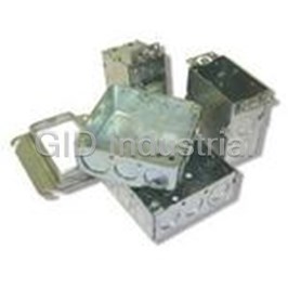
Handy Bx Cvrs-1/8 Raised 100-K
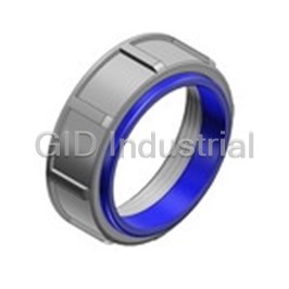
3 1/2 Insulated Bushing Malleable Iron 1230
4 Insulated Bushing Malleable Iron Blue 1231
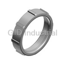
3/4 Aluminum Bushing. For Use With Rigid 123AL
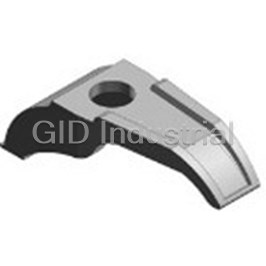
Access Underground Feeder Cable Connectors 1344
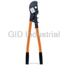
Accessories, Upper Die For Tbm-6 13472
Request a Quote

The quote request has been received
Close

Facing challenges or have inquiries? Feel free to contact us!
Call Us +1-469-283-2440
What they say about us
FANTASTIC RESOURCE
One of our top priorities is maintaining our business with precision, and we are constantly looking for affiliates that can help us achieve our goal. With the aid of GID Industrial, our obsolete product management has never been more efficient. They have been a great resource to our company, and have quickly become a go-to supplier on our list!
Bucher Emhart Glass
EXCELLENT SERVICE
With our strict fundamentals and high expectations, we were surprised when we came across GID Industrial and their competitive pricing. When we approached them with our issue, they were incredibly confident in being able to provide us with a seamless solution at the best price for us. GID Industrial quickly understood our needs and provided us with excellent service, as well as fully tested product to ensure what we received would be the right fit for our company.
Fuji
HARD TO FIND A BETTER PROVIDER
Our company provides services to aid in the manufacture of technological products, such as semiconductors and flat panel displays, and often searching for distributors of obsolete product we require can waste time and money. Finding GID Industrial proved to be a great asset to our company, with cost effective solutions and superior knowledge on all of their materials, it’d be hard to find a better provider of obsolete or hard to find products.
Applied Materials
CONSISTENTLY DELIVERS QUALITY SOLUTIONS
Over the years, the equipment used in our company becomes discontinued, but they’re still of great use to us and our customers. Once these products are no longer available through the manufacturer, finding a reliable, quick supplier is a necessity, and luckily for us, GID Industrial has provided the most trustworthy, quality solutions to our obsolete component needs.
Nidec Vamco
TERRIFIC RESOURCE
This company has been a terrific help to us (I work for Trican Well Service) in sourcing the Micron Ram Memory we needed for our Siemens computers. Great service! And great pricing! I know when the product is shipping and when it will arrive, all the way through the ordering process.
Trican Well Service
GO TO SOURCE
When I can't find an obsolete part, I first call GID and they'll come up with my parts every time. Great customer service and follow up as well. Scott emails me from time to time to touch base and see if we're having trouble finding something.....which is often with our 25 yr old equipment.
ConAgra Foods