

 Manufacturers
WAKEFIELD-VETTE 132-5-G9
Description
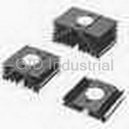
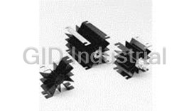
Heat Sink Passive Aluminum Alloy 0.17°C/W Gold Iridite
132-5-G9
Part Number
132-5-G9
Price
Request Quote
Manufacturer
WAKEFIELD-VETTE
Lead Time
Request Quote
Category
Thermal Management » Heat Sink
Specifications
Manufacturer
Wakefield-Vette
Manufacturers Part #
132-5-G9
Sub-Category
Thermal Management Heat Sinks
Selling Alternatives
132-5-B9
Factory Pack Quantity
1
Datasheet

Extracted Text
WTS001_p50-68 6/14/07 10:46 AM Page 57 Precision Compression Clamp Systems PRECISION COMPRESSION MOUNTING CLAMP SYSTEMS Wakefield Engineering compression pack heat sinks and clamp systems provide electrical and mounting and cooling are available separately for all standard compression requirements from industrial equipment manufacturers with complete system solutions for proper installation and 800 lbs (362.9 kg) to 16,000 lbs (7,257.5 kg) force in both natural and forced convection ap- heat dissipation for high-power compression pack semiconductor. All components for device plications. Clamp Assembly Maximum Clamping Force Maximum Diameter (Ref) Crossbar Stud Centerline Series Force Range Power Disc Device to Centerline Dimension 130 Series 800 lbs (362.9 kg) - 2,000 lbs (907.2 kg) 2.25 in. (57.2 mm) 2.750 in. (69.9 mm) Ref 139 Series 3,000 lbs (1,360.8 kg) and 5,000 lbs (2,268.0 kg) 3.50 in. (88.9 mm) 4.000 in. (101.6 mm) Ref 143 Series 1,000 lbs (453.6 kg) - 6,000 lbs (2,721.6 kg) 3.50 in. (88.9 mm) 4.000 in. (101.6 mm) Ref 144 Series 1,000 lbs (453.6 kg) - 6,000 lbs (2,721.6 kg) 4.00 in. (101.6 mm) 4.625 in. (117.5 mm) Ref 145 Series 2,000 lbs (907.2 kg) - 10,000 lbs (4,535.9 kg) 4.50 in. (114.3 mm) 5.500 in. (139.7 mm) Ref 146 Series 8,000 lbs (3,628.8 kg) - 16,000 lbs (7,257.5 kg) 5.25 in. (133.4 mm) 6.000 in. (152.4 mm) Ref 131/132/133 Series High-Performance Press Pack Heat Sinks These high-quality mounting clamp assemblies are the worldwide standard for mounting, lected (based on maximum clamping force required), will provide the necessary vertical clear- compression, and clamping press-pack SCR, thyristor, rectifier, and other high power disc ance space. For the 130 and 139 Series, this determination is made by subtracting the chosen packaged devices utilized in power distribution equipment, industrial controls, transportation spring assembly “Z” dimension (refer to dimensional tables) from the crossbar assembly “X” systems, and power supply and conversion systems. dimension minimum and maximum values, to calculate the available device mounting space clearance for the particular assembly combination. Spring assembly “Z” dimension is the di- Clamp assemblies will accommodate devices with overall case diameters to 5.25 in. (133.4 mension measured from the spring assembly device mounting surface to the spring assembly mm) maximum. Vertical device mounting space available for assemblies is determined by se- top surface. Some series have fixed dimensions for alpha characters. All spring assemblies are lecting an appropriate series crossbar by length which, when a series spring assembly is se- designed with a force indicator gauge. Compression Mounting Clamp Assemblies for Semiconductors to 2.25 in. (57.2mm) Diameter 130 SERIES 130 SERIES CROSSBAR MECHANICAL DIMENSIONS 800 lb - 2,000 lb (362.8 kg - 907.2 kg) Crossbar Device Mounting, Surface to Spring Assembly Top Surface Dimension Model “X” Dimension Weight No. Min. Max. lbs. (grams) In. (mm) 130-A 1.74 (44.2) - 2.12 (53.8) 0.4 (181.44) 130-B 2.05 (52.1) - 2.43 (61.7) 0.418 (189.60) 130-C 2.36 (59.9) - 2.74 (69.6) 0.427 (193.68) 130-D 2.67 (67.8) - 3.05 (77.5) 0.437 (198.22) 130-E 2.98 (75.7) - 3.36 (85.3) 0.447 (202.76) 130-F 3.29 (83.6) - 3.67 (93.2) 0.461 (209.11) 130-G 3.60 (91.4) - 3.98 (101.1) 0.476 (215.91) 130-H 3.91 (99.3) - 4.29 (109.0) 0.486 (220.45) 130-J 4.22 (107.2) - 4.60 (116.8) 0.497 (225.44) 130-K 4.53(115.1) - 4.91 (124.7) 0.51 (231.33) 130-L 4.34 (122.9) - 5.22 (132.6) 0.52 (235.87) 130-M 5.15 (130.8) - 5.53 (140.5) 0.534 (242.22) 130-N 5.46 (138.7) - 5.84 (147.3) 0.544 (246.75) 130-P 5.77 (146.6) - 6.15 (156.2) 0.559 (253.56) 130 SERIES SPRING ASSEMBLY Model No. of “Z”Dim. Max Force Weight No. Leaves in. (mm) lb (kg) lbs (gms) 130-1 2 0.90 (22.9) 2,000 (907.2) 0.331 (150.14) 130-2 2 0.50 (12.7) 800 (362.8) 0.19 (86.18) 130-3 3 0.61 (15.5) 1,200 (544.3) 0.219 (99.34) 130-4 4 0.72 (18.3) 1,600 (727.8) 0.333 (151.05) Dimensions: in. (mm) 130-5 5 0.83 (21.1) 2,000 (907.2) 0.408 (185.07) Notes: 1. Spring assemblies are stainless steel leaves with a force indicator gauge, except the lowest cost Type 130-1 spring assembly manufac- tured from automotive grade stainless steel. Order Guide: Dimensions: Order Crossbar and Spring Assembly in. (mm) separately by type number from table. lb. (kg) 57 WTS001_p50-68 6/14/07 10:46 AM Page 58 Precision Compression Clamp Systems PRECISION COMPRESSION MOUNTING CLAMP SYSTEMS Compression mounting clamp assemblies for semiconductors to 3.50 in. (88.9 mm) Diameter 139 SERIES 139 SERIES CROSSBAR 3,000 lb - 5,000 lb, (1,360.8 kg - 2,268.0 kg), Crossbar Device Mounting, Surface to Spring Assembly, Top Surface Dimension 139-3 SERIES CROSSBAR - 3,000 LB (1,360.8) 139-5 SERIES CROSSBAR - 5,000 LB (2,268.0) Model “X” Dimension Weight Model “X” Dimension Weight No. Min Max lbs. (grams) No. Min Max lbs. (grams) in. (mm) in. (mm) 139-3A 1.52 (38.6) – 1.89 (48.0) 0.689 (312.52) 139-5A 1.52 (38.6) – 1.89 (48.0) 0.94 (426.38) 139-3B 1.83 (46.5) – 2.21 (56.1) 0.7 (317.51) 139-5B 1.83 (46.5) – 2.21 (56.1) 0.96 (435.45) 139-3C 2.14 (54.4) – 2.52 (64.0) 0.706 (320.24) 139-5C 2.14 (54.4) – 2.52 (64.0) 0.98 (444.52) 139-3D 2.45 (62.2) – 2.83 (71.9) 0.721 (327.04) 139-5D 2.45 (62.2) – 2.83 (71.9) 1.01 (458.13) 139-3E 2.77 (70.4) – 3.14 (79.8) 0.732 (332.03) 139-5E 2.77 (70.4) – 3.14 (79.8) 1.02 (462.66) 139-3F 3.08 (78.2) – 3.45 (87.6) 0.741(336.11) 139-5F 3.08 (78.2) – 3.45 (87.6) 1.033 (468.56) 139-3G 3.39 (86.1) – 3.77 (95.8) 0.762 (345.64) 139-5G 3.39 (86.1) – 3.77 (95.8) 1.053 (477.63) 139-3H 3.70 (94.0) – 4.08 (103.6) 0.773 (350.63) 139-5H 3.70 (94.0) – 4.08 (103.6) 1.074 (487.64) 130-3J 4.01 (101.9 – 4.39 (111.5) 0.784 (355.62) 139-5J 4.33 (101.9) – 4.39 (111.5) 1.064 (482.62) 139-3K 4.33 (110.0) – 4.70 (119.4) 0.79 (358.34) 139-5K 4.33 (110.0) – 4.70 (119.4) 1.075 (487.61) 139-3L 4.64 (117.9) – 5.01 (127.3) 0.793 (359.70) 139-5L 4.64 (117.9) – 5.01 (127.3) 1.088 (493.51) 139-3M 4.95 (125.7) – 5.33 (135.4) 0.796 (361.06) 139-5M 4.95 (125.7) – 5.33 (135.4) 1.102 (499.86) 139-3N 5.26 (133.6) – 5.64 (143.3) 0.832 (377.39) 139-5N 5.26 (133.6) – 5.64 (143.3) 1.11 (503.49) 139-3P 5.57 (141.5) – 5.95 (151.1) 0.838 (380.11) 139-5P 5.57 (141.5) – 5.95 (151.1) 1.171 (531.16) CROSSBAR HEIGHT AND WIDTH Order Guide: Dimensions: Series Height “A" Reference Width “B” Order Crossbar and Spring Assembly in. (mm) Number in. (mm) Reference in. (mm) separately by type number from table. lb. (kg) 139-3 0.72 (18.3) 0.95 (24.1) 139-5 1.02 (25.9) 0.83 (21.1) 139 SERIES SPRING ASSEMBLY Model Number of "Z" Dimension Maximum Force Number Leaves in. (mm) lb. (kg) 139-1 1 0.87(22.1) 3,000 (1,360.8) 139-2 2 1.25(31.8) 5,000 (2,268.0) MECHANICAL DIMENSIONS Dimensions: in. (mm) 58 WTS001_p50-68 6/14/07 10:46 AM Page 59 Precision Compression Clamp Systems PRECISION COMPRESSION MOUNTING CLAMP SYSTEMS Compression Mounting Clamp Assemblies for Semiconductors to 3.50 in (88.9 mm) Diameter 143 SERIES 143 SERIES CROSSBAR MECHANICAL DIMENSIONS 2,000 lb - 6,000 lb (907.2 kg - 2,721.6 kg) Crossbar Device Mounting, Surface to Spring Assembly, Top Surface Dimension Model “X” Dimension Overall Weight No. Min Max Height “H” lbs. (grams) In. (mm) In. (mm) 143-A 1.30 (33.0) – 1.80 (45.7) 4.68 (118.9) 1.100 (498.95) 143-B 1.86 (45.7) – 2.30 (58.4) 5.18 (131.6) 1.125 (510.29) 143-C 2.30 (58.4) – 2.80 (71.1) 5.68 (144.3) 1.150 (521.63) 143-D 2.80 (71.1) – 3.30 (83.8) 6.18 (157.0) 1.175 (532.97) 143-E 3.30 (83.8) – 3.80 (96.5) 6.68 (169.7) 1.200 (544.31) 143-F 3.80 (96.5) – 4.30 (109.2) 7.18 (182.4) 1.225 (555.65) 143-G 4.30 (109.2) – 4.80 (121.9) 1.68 (195.1) 1.250 (566.99) 143-H 4.80 (121.9) – 5.30 (134.6) 8.18 (207.8) 1.275 (578.33) 143-J 5.30 (134.6) – 5.80 (147.3) 8.68 (220.5) 1.300 (589.67) 143-K 5.80 (147.3) – 6.30 (160.0) 9.18 (233.2) 1.325 (601.00) 143-L 6.30 (160.0) – 6.80 (172.7) 9.68 (245.9) 1.350 (612.35) Dimensions: in. (mm) 143 SERIES SPRING ASSEMBLY Order Guide: Dimensions: Model Number of Max. Clamping Weight Order Crossbar and Spring Assembly in. (mm) Number Leaves Force lb. (kg) lb. (grams) separately by type number from table. lb. (kg) 143-2 2 6,000 (2,721.6) 0.813 (368.77) Compression Mounting Clamp Assemblies for Semiconductors to 4.00 in (101.6mm) Diameter 144 SERIES 144 SERIES CROSSBAR MECHANICAL DIMENSIONS 1,000 lb - 6,000 lb (453.6 kg - 2,721.6 kg) Crossbar Device Mounting, Surface to Spring Assembly Top Surface Dimension Model “X” Dimension Weight No. Min Max lbs (grams) In. (mm) 144-A 1.50 (38.1) – 2.00 (50.8) 1.231 (558.37) 144-B 2.00 (50.8) – 2.50 (63.5) 1.262 (572.43) 144-C 2.50 (63.5) – 3.00 (63.5) 1.285 (582.87) 144-D 3.00 (76.2) – 3.50 (88.9) 1.310 (594.21) 144-E 3.50 (88.9) – 4.00 (101.6) 1.352 (613.26) 144 SERIES SPRING ASSEMBLY Model Clamping Force Range Weight No. lb (kg) lbs (grams) 144-2 1,000 (453.6) – 6,000 (2,721) 1.772 (803.77) Order Guide: Dimensions: Order Crossbar and Spring Assembly in. (mm) separately by type number from table. lb. (kg) Dimensions: in. (mm) 59 WTS001_p50-68 6/14/07 10:46 AM Page 60 Precision Compression Clamp Systems PRECISION COMPRESSION MOUNTING CLAMP SYSTEMS Compression Mounting Clamp Assemblies for Semiconductors to 4.50 in (114.3 mm) Diameter 145 SERIES 145 SERIES CROSSBAR 2,000 lb - 10,000 lb (907.2 kg - 4,535.9 kg) Crossbar Device Mounting, Surface to Spring Assembly, Top Surface Dimension Model “X” Dimension Overall Weight No. Min Max Height “H” lbs. (grams) In. (mm) In. (mm) 145-A 1.75 (44.5) – 2.50 (63.5) 6.00 (152.4) 3.845 (1744.06) MECHANICAL DIMENSIONS 145-B 2.50 (63.5) – 3.25 (82.6) 6.75 (171.5) 3.987 (1808.47) 145-C 3.25 (82.6) – 4.00 (101.6) 7.50 (190.5) 4.06 (1841.58) 145-D 4.00 (101.6) – 4.75 (120.7) 8.25 (209.6) 4.187 (1899.19) 145-E 4.75 (120.7) – 5.50 (139.7) 9.00 (228.6) 4.37 (1982.20) 145-F 5.50 (139.7) – 6.25 (158.8) 9.75 (247.7) 4.459 (2022.57) 145 SERIES SPRING ASSEMBLY Model Clamping Force Range Weight No. lb (kg) lbs (grams) 145-2 2,000 (907.2) – 10,000 (4,535.9) 2.01 (911.72) Order Guide: Dimensions: Order Crossbar and Spring Assembly in. (mm) separately by type number from table. lb. (kg) Dimensions: in. (mm) Compression Mounting Clamp Assemblies for Semiconductors to 5.25 in (133.5 mm) Diameter 146 SERIES 146 SERIES CROSSBAR 8,000 lb -16,000 lb (3,628.7 kg - 7,257.4 kg) Crossbar Device Mounting, Surface to Spring Assembly, Top Surface Dimension Model “X” Dimension Overall Weight No. Min Max Height “H” In. (mm) In. (mm) lbs. (grams) 146-A 1.54 (39.1) – 2.29 (58.2) 5.92 (150.4) 3.813 (1729.55) 146-B 2.29 (58.2) – 3.04 (77.2) 6.67 (169.4) 3.938 (1786.25) MECHANICAL DIMENSIONS 146-C 3.04 (77.2) – 3.79 (96.3) 7.42 (188.5) 4.063 (1842.95) 146-D 3.79 (96.3) – 4.54 (115.3) 8.17 (207,5) 4.188 (1899.64) 146-E 4.54 (115.3) – 5.29 (134.4) 8.92 (226.6) 4.313 (1956.34) 146-F 5.29 (134.4) – 6.04 (153.4) 9.67 (245.6) 4.438 (2013.04) 146-G 6.04 (153.4) – 6.79 (172.5) 10.42 (264.7) 4.563 (2069.74) 146 SERIES SPRING ASSEMBLY Model Number of Clamping Force Range Maximum Force Number Leaves lb (kg) lb (grams) 146-2 2 8,000 (3,628.7) - 16,000 (7,257.5) 2,688 (1,219.26) Order Guide: Dimensions: Order Crossbar and Spring Assembly in. (mm) separately by type number from table. lb. (kg) Dimensions: in. (mm) 60 WTS001_p50-68 6/14/07 10:46 AM Page 61 Precision Compression Clamp Systems 132/133 SERIES HIGH-PERFORMANCE HEAT SINKS FOR COMPRESSION TYPE DEVICES 132/133 SERIES MULTIPLE ASSEMBLY CONFIGURATION Dimensions: in.(mm) Finish: B = Black Anodized G = Gold Iridite Material: Aluminum Alloy Thermal Performance (2) at Typical Load (1) Standard P/N Nominal Dimensions: Clamp Natural Convection Black Gold Width Length “A” Height System Convection (°C/W) @ (4, 5) (5) (3) Anodize Iridite in. (mm) in. (mm) in. (mm) Series (°C/W) 500 LFM) 132-4.5B 132-4.5G 5.000 (127.0) 4.500 (114.3) 2.250 (57.2) 130 0.61 0.170 Type Use with A B C D 132-10B 132-10G 5.000 (127.0) 10.000 (254.0) 2.250 (57.2) 130 0.38 0.130 132-4.5 – See Fig.132 132-15.5B 132-15.5G 5.000 (127.0) 15.500 (393.7) 2.250 (57.2) 130 0.28 0.100 132-10 2 ea 132-4.5 2.25 5.50 – 10.0 132-5-B9 132-5-G9 5.000 (127.0) 5.000 (127.0) 2.250 (57.2) 139 0.61 0.170 132-15.5 3 ea 132-4.5 2.25 5.50 5.50 15.5 132-11-B9 132-11-G9 5.000 (127.0) 11.000 (299.4) 2.250 (57.2) 139 0.37 0.120 133-4.5 ––See Fig.133 133-4.5B 133-4.5G 7.000 (139.2) 4.500 (114.3) 3.125 (79.4) 130 0.37 0.110 133-7.5B 133-7.5G 7.000 (139.2) 7.500 (190.5) 3.125 (79.4) 130 0.28 0.085 133-7.5 – – See Fig.133 133-10B 133-10G 7.000 (139.2) 10.000 (254.0) 3.125 (79.4) 130 0.26 0.082 133-10 2 ea 133-4.5 2.25 5.50 – 10.0 133-5-B9 133-5-G9 7.000 (139.2) 5.000 (127.0) 3.125 (79.4) 139 0.37 0.110 132-5-9** – – See Fig.132 133-7.5-B9 133-7.5-G9 7.000 (139.2) 7.500 (190.5) 3.125 (79.4) 139 0.28 0.085 132-11-9** 2 ea 132-5-9 2.50 6.00 - 11.00 133-11-B9 133-11-G9 7.000 (139.2) 11.000 (279.4) 3.125 (79.4) 139 0.24 0.076 133-5-9** – – See Fig. 133 133-7.5-9** – – See Fig. 133 Notes: 133-11-9** 2 ea 133-5-9 2.50 6.00 – 11.00 1. Nominal dimensions for one heat sink of this type. 4. Black anodize finish [1.875 in. (47.6 mm) diameter spot 2. Thermal performance values shown are per pair of heat sinks. face. Device mounting surface area free of finish]. 3. Natural convection performance at 50°C heat sink rise above 5. Predrilled heat sinks accept 130 and 139 Series clamp ** -9 indicates heat sinks drilled for 139 clamp. ambient. systems. 132 SERIES 133 SERIES NATURAL AND FORCED CONVECTION CHARACTERISTICS NATURAL AND FORCED CONVECTION CHARACTERISTICS MECHANICAL DIMENSIONS (EXTRUSION PROFILE 3560-2) MECHANICAL DIMENSIONS (EXTRUSION PROFILE 3559-2) Series Series **132-4.5 **133-4.5 **132-10 **132-15.5 **133-7.5 **132-5-9 **133-10 **132-11-9 **133-5-9 **133-7.5-9 **133-11-9 Dimensions: in. (mm) 61
Frequently asked questions
How does Electronics Finder differ from its competitors?

Is there a warranty for the 132-5-G9?
Which carrier will Electronics Finder use to ship my parts?
Can I buy parts from Electronics Finder if I am outside the USA?
Which payment methods does Electronics Finder accept?
Why buy from GID?

Quality
We are industry veterans who take pride in our work

Protection
Avoid the dangers of risky trading in the gray market

Access
Our network of suppliers is ready and at your disposal

Savings
Maintain legacy systems to prevent costly downtime

Speed
Time is of the essence, and we are respectful of yours
Related Products
Heat Sink Passive Stud Mount Aluminum Alloy 0.19°C/W Black Anodized 1245
Heat Sink Passive Aluminum Alloy 0.13°C/W Black Anodized 132-10B
Heat Sink Passive Aluminum Alloy 0.13°C/W Gold Iridite 132-10G
Heat Sink Passive Aluminum Alloy 0.12°C/W Black Anodized 132-11-B9
Heat Sink Passive Aluminum Alloy 0.12°C/W Gold Iridite 132-11-G9
Heat Sink Passive Aluminum Alloy 0.1C/W Black Anodized 132-15.5B
Request a Quote

The quote request has been received
Close

Facing challenges or have inquiries? Feel free to contact us!
Call Us +1-469-283-2440
What they say about us
FANTASTIC RESOURCE
One of our top priorities is maintaining our business with precision, and we are constantly looking for affiliates that can help us achieve our goal. With the aid of GID Industrial, our obsolete product management has never been more efficient. They have been a great resource to our company, and have quickly become a go-to supplier on our list!
Bucher Emhart Glass
EXCELLENT SERVICE
With our strict fundamentals and high expectations, we were surprised when we came across GID Industrial and their competitive pricing. When we approached them with our issue, they were incredibly confident in being able to provide us with a seamless solution at the best price for us. GID Industrial quickly understood our needs and provided us with excellent service, as well as fully tested product to ensure what we received would be the right fit for our company.
Fuji
HARD TO FIND A BETTER PROVIDER
Our company provides services to aid in the manufacture of technological products, such as semiconductors and flat panel displays, and often searching for distributors of obsolete product we require can waste time and money. Finding GID Industrial proved to be a great asset to our company, with cost effective solutions and superior knowledge on all of their materials, it’d be hard to find a better provider of obsolete or hard to find products.
Applied Materials
CONSISTENTLY DELIVERS QUALITY SOLUTIONS
Over the years, the equipment used in our company becomes discontinued, but they’re still of great use to us and our customers. Once these products are no longer available through the manufacturer, finding a reliable, quick supplier is a necessity, and luckily for us, GID Industrial has provided the most trustworthy, quality solutions to our obsolete component needs.
Nidec Vamco
TERRIFIC RESOURCE
This company has been a terrific help to us (I work for Trican Well Service) in sourcing the Micron Ram Memory we needed for our Siemens computers. Great service! And great pricing! I know when the product is shipping and when it will arrive, all the way through the ordering process.
Trican Well Service
GO TO SOURCE
When I can't find an obsolete part, I first call GID and they'll come up with my parts every time. Great customer service and follow up as well. Scott emails me from time to time to touch base and see if we're having trouble finding something.....which is often with our 25 yr old equipment.
ConAgra Foods