

 Manufacturers
ADVANCED ENERGY 0.6M12-N0.5
Description
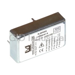
MICRO-SIZED DC TO REGULATED HIGH-VOLTAGE DC CONVERTER, LOW-CURRENT, LOW-PROFILE/PCB-MOUNT MODULE, UNIPOLAR, SINGLE OUTPUT
Part Number
0.6M12-N0.5
Price
Request Quote
Manufacturer
ADVANCED ENERGY
Lead Time
Request Quote
Category
Capacitors » DC-DC Converter
Specifications
Manufacturer
Advanced Energy
Manufacturers Part #
0.6M12-N0.5
Brand
UltraVolt
Series
M Series
Factory Pack Quantity
5
Dimensions
1.85 x 1.10 x 0.47"
Input Type
DC
Input Voltage Nominal
12 VDC
Mechanical Style
Non-Isolated / POL
Mounting
Through Hole
Number of Outputs
1
Operating Temperature
- 10 to + 65°C
Output Amps 1
0.00083 A
Output Voltage V1 Nominal
600 VDC
Package Type
Enclosed
Power
0.5 W
Subcategory
DC-DC Converter
Datasheet

Extracted Text
ULTRAVOLT® M SERIES MINIATURE, MICRO-SIZED HIGH VOLTAGE BIASING SUPPLIES Single-output, micro-sized HV modules The miniature, micro-sized M series is the ideal solution for applications requiring biasing voltage ranging from 3 0 to 3000 V and very small current—only 16.4 cc (1.00 in ). Less than 12.7 mm (0.5") high, these modules are ideal for low-profile applications. Features Typical Applications › Seven models from 0 to 600, › Bias supplies 1000, 1250, 1500, 2000, 2500, › Electrostatic chucks or 3000 V › Hand held x-ray florescence › Output power: 0.5, 0.8, or 1 W (XRF) › Tight line/load regulation › Avalanche photo diodes (APD) › Arc and continuous short › Photomultiplier tubes (PMT) circuit protection › Silicon detector (SiD) › Self-restoring output voltage › X-ray flat panel detector (FPD) › Low cost › Ionization chamber detector › Miniature and lightweight › Voltage monitoring › Low ripple (0.01% peak to peak) › Optional flying lead for high voltage output PARAMETER SPECIFICATIONS UNITS 5 ±0.5 (2 to 3 kV ONLY), 12 ±1, 15 ±1 (600 V to 1.5 kV ONLY), or 24 ±2 VDC Input Voltage Vin (Pins 1 and 2) 5 (2 to 3 kV ONLY) 12 V Input Voltage No load: 55, full load: 450 No load: 45, full load: 200 mA Input Current Fixed positive and fixed negative - Polarity 0 to 600 0 to 1000 VDC Output Voltage 12 15 24 12 15 24 VDC Input Voltage 0.5 0.8 1 0.5 0.8 1 W Output Power 0.83 1.33 1.67 0.5 0.8 1 mA Output Current 0 to 1250 0 to 1500 VDC Output Voltage 12 15 24 12 15 24 VDC Input Voltage 0.5 0.8 1 0.5 0.8 1 W Output Power 0.4 0.64 0.8 0.33 0.53 0.67 mA Output Current 10 to 100 K (potentiometer across Vref. and signal ground, wiper to adjust) - HV Setting < 0.01% of full output voltage for no load to full load VDC Load Voltage Regulation < 0.01% of full output voltage over specified input voltage range VDC Line Voltage Regulation < 0.01% at full load V pk to pk Residual Ripple 100 ppm/°C for the max output voltage after starting and over temperature range 0 to - Temperature Coefficient 50°C +1 V/1 kV max or -1 V/-1 kV max according to model polarity output impedance = 200 kΩ - Output Voltage Monitoring (600 to 1500 V) ±1% 12 to 24 V input only: 0 to +5 V±2% VDC Output Voltage Monitoring (2 to 3 kV) 5 V inputs: 0 to +2.5 V±2% 12 to 24 V input only: 5 V ±1%, TC: 100 ppm/°C, max output current: 1 mA - Reference Voltage 5 V inputs: 2.5 V ±1%, TC: 100 ppm/°C, max output current: 1 mA -10 to +65, full load, max Eout, case temp °C Operating Temperature -40 to +70 °C Storage Temperature Arc and short circuit protection - Safeguards Flying lead for HV output - Options Enable/disable (ON/OFF): 0 to +0.5 V enable, +2.4V to V_input disable (default = - Enhanced Interface (-EI) disable) Option (2 to 3 kV Only) Output current monitor (5 V input only): 0 to +2.5 V ±2% Output current monitor (12 to 24 V input): 0 to +5.0 V ±2% - PARAMETER SPECIFICATIONS UNITS 5 ±0.5 (2 to 3 kV ONLY), 12 ±1, 15 ±1 (600 V to 1.5 kV ONLY), or 24 ±2 VDC Input Voltage Vin (Pins 1 and 2) 15 (600 V to 1.5 kV ONLY) 24 V Input Voltage No load: 40, full load: 190 No load: 35,k full load: 160 mA Input Current Fixed positive and fixed negative - Polarity 0 to 2000 0 to 2500 VDC Output Voltage 5 12 24 5 12 24 VDC Input Voltage 0.5 0.8 1 0.5 0.8 1 W Output Power 0.25 0.40 0.50 0.20 0.32 0.40 mA Output Current 0 to 3000 VDC Output Voltage 5 12 24 VDC Input Voltage 0.5 0.8 1 W Output Power 0.167 0.267 0.333 mA Output Current 10 to 100 K (potentiometer across Vref. and signal ground, wiper to adjust) - HV Setting < 0.01% of full output voltage for no load to full load VDC Load Voltage Regulation < 0.01% of full output voltage over specified input voltage range VDC Line Voltage Regulation < 0.01% at full load V pk to pk Residual Ripple 100 ppm/°C for the max output voltage after starting and over temperature range - Temperature Coefficient 0 to 50°C +1 V/1 kV max or -1 V/-1 kV max according to model polarity output impedance - Output Voltage Monitoring (600 to 1500 V) = 200 kΩ ±1% 12 to 24 V input only: 0 to +5 V±2% VDC Output Voltage Monitoring (2 to 3 kV) 5 V inputs: 0 to +2.5 V±2% 12 to 24 V input only: 5 V ±1%, TC: 100 ppm/°C, max output current: 1 mA - Reference Voltage 5 V inputs: 2.5 V ±1%, TC: 100 ppm/°C, max output current: 1 mA -10 to +65, full load, max Eout, case temp °C Operating Temperature -40 to +70 °C Storage Temperature Arc and short-circuit protection - Safeguards Flying lead for HV output - Options Enable/disable (ON/OFF): 0 to +0.5 V enable, +2.4V to V_input disable (default = - Enhanced Interface (-EI) disable) Option (2 to 3 kV Only) Output current monitor (5 V input only): 0 to +2.5 V ±2% Output current monitor (12 to 24 V input): 0 to +5.0 V ±2% - FLYING LEAD OPTION -WS Note: Pins 7 and 8 are available for 2 k to 3 kV units with enhanced interface option ONLY. Drawing views: third angle projections. Measurements are in inches (millimeters). PHYSICAL SPECIFICATIONS Steel, tin-plated thickness 0.5 mm (0.02") Construction Insulation: fully potted in an epoxy resin 16.4 cc (1.00 in³) Volume 35 g (1.23 oz) Weight Tolerance ±0.76 mm (0.030") Overall ±0.38 mm (0.015") Pin to Pin ±0.51 mm (0.020") Pin to Tab ±0.25 mm (0.010") Tab to Tab Notes: 0.47 mm (0.019") round pins, length: 3 mm (0.12"), spacing: 2.54 mm (0.1") PCB mounting through 4 mounting tabs, length: 5 mm (0.2"), width: 1.5 mm (0.059"), thickness: 0.5 mm (0.02") Optional flying lead for HV output: coaxial cable (RG178), diameter: 2 mm (0.079"), length: 500 mm (19.685") CONNECTIONS Pin Function POSITIVE POWER INPUT 1 POWER GROUND 2 SIGNAL GROUND 3 REMOTE ADJUST INPUT 4 REFERENCE VOLTAGE 5 VOLTAGE MONITOR 6 CURRENT MONITOR (available with -EI option only) 7 ENABLE (available with -EI option only) 8 HV OUTPUT 9 Note: Mounting tabs must be connected to ground. ORDERING INFORMATION 0 to 600 VDC Output 0.6 M Type 0 to 1000 VDC Output 1 M 0 to 1250 VDC Output 1.25 M 0 to 1500 VDC Output 1.5 M 0 to 2000 VDC Output 2 M 0 to 2500 VDC Output 2.5 M 0 to 3000 VDC Output 3 M 5 VDC Nominal (2 to 3 kV only) 5 Input 12 VDC Nominal 12 15 VDC Nominal (600 V to 1.5 kV only) 15 24 VDC Nominal 24 0.5 W Output 0.5 Power 0.8 W Output 0.8 1 W Output 1 Tin Steel Case (Standard) Case Positive Output -P Polarity Negative Output -N Shielded Flying Lead for HV Output (600 V to 1.5 kV) -WS Option Flying Lead for HV Output (2 to 3 kV only) -W Current Monitor/Enable Pin (2 to 3 kV only) -EI Example: 1.5M24-P1-WS Voltage Option IEC-60950-1 Type Model Power Non-RoHS compliant units are available. Please contact the factory for more information. Input Polarity Popular accessories ordered with this product include the PCB-CONN-M/V. The M series is not available in all territories. Please contact Advanced Energy for details concerning sales in your area. For international contact information, visit advanced-energy.com. ENG-HV-Mseries-230-J 11.16 Specifications are subject to change without notice. ©2016 Advanced Energy Industries, Inc. All rights reserved. Advanced Energy® AE®, and UltraVolt® are U.S. trademarks of Advanced Energy Industries, Inc.
Frequently asked questions
How does Electronics Finder differ from its competitors?

Is there a warranty for the 0.6M12-N0.5?
Which carrier will Electronics Finder use to ship my parts?
Can I buy parts from Electronics Finder if I am outside the USA?
Which payment methods does Electronics Finder accept?
Why buy from GID?

Quality
We are industry veterans who take pride in our work

Protection
Avoid the dangers of risky trading in the gray market

Access
Our network of suppliers is ready and at your disposal

Savings
Maintain legacy systems to prevent costly downtime

Speed
Time is of the essence, and we are respectful of yours
Related Products
Ultra-small DC to Regulated DC Converter to 100V, Low-current, PCB-Mount Module, Single Output
Ultra-small DC to Regulated DC Converter to 100V, Low-current, PCB-Mount Module, Single Output
EXTRA-SMALL DC TO REGULATED HIGH-VOLTAGE DC CONVERTER, PCB-MOUNT MODULE, SINGLE OUTPUT
EXTRA-SMALL DC TO REGULATED HIGH-VOLTAGE DC CONVERTER, PCB-MOUNT MODULE, SINGLE OUTPUT
0.1 W, 11.5 -15.5 VDC Vin, Single Output, 200 VDC@0.0005 A Industrial DC-DC Converter
EXTRA-SMALL DC TO REGULATED HIGH-VOLTAGE DC CONVERTER, PCB-MOUNT MODULE, SINGLE OUTPUT
Request a Quote

The quote request has been received
Close

Facing challenges or have inquiries? Feel free to contact us!
Call Us +1-469-283-2440
What they say about us
FANTASTIC RESOURCE
One of our top priorities is maintaining our business with precision, and we are constantly looking for affiliates that can help us achieve our goal. With the aid of GID Industrial, our obsolete product management has never been more efficient. They have been a great resource to our company, and have quickly become a go-to supplier on our list!
Bucher Emhart Glass
EXCELLENT SERVICE
With our strict fundamentals and high expectations, we were surprised when we came across GID Industrial and their competitive pricing. When we approached them with our issue, they were incredibly confident in being able to provide us with a seamless solution at the best price for us. GID Industrial quickly understood our needs and provided us with excellent service, as well as fully tested product to ensure what we received would be the right fit for our company.
Fuji
HARD TO FIND A BETTER PROVIDER
Our company provides services to aid in the manufacture of technological products, such as semiconductors and flat panel displays, and often searching for distributors of obsolete product we require can waste time and money. Finding GID Industrial proved to be a great asset to our company, with cost effective solutions and superior knowledge on all of their materials, it’d be hard to find a better provider of obsolete or hard to find products.
Applied Materials
CONSISTENTLY DELIVERS QUALITY SOLUTIONS
Over the years, the equipment used in our company becomes discontinued, but they’re still of great use to us and our customers. Once these products are no longer available through the manufacturer, finding a reliable, quick supplier is a necessity, and luckily for us, GID Industrial has provided the most trustworthy, quality solutions to our obsolete component needs.
Nidec Vamco
TERRIFIC RESOURCE
This company has been a terrific help to us (I work for Trican Well Service) in sourcing the Micron Ram Memory we needed for our Siemens computers. Great service! And great pricing! I know when the product is shipping and when it will arrive, all the way through the ordering process.
Trican Well Service
GO TO SOURCE
When I can't find an obsolete part, I first call GID and they'll come up with my parts every time. Great customer service and follow up as well. Scott emails me from time to time to touch base and see if we're having trouble finding something.....which is often with our 25 yr old equipment.
ConAgra Foods