

 Manufacturers
ADVANCED ENERGY 1/16AA12-N4-M-E
Description
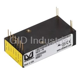
COMPACT DC TO REGULATED HIGH-VOLTAGE DC CONVERTER, PCB OR CHASSIS-MOUNT MODULE, SINGLE OUTPUT
Part Number
1/16AA12-N4-M-E
Price
Request Quote
Manufacturer
ADVANCED ENERGY
Lead Time
Request Quote
Category
Capacitors » DC-DC Converter
Specifications
Manufacturer
Advanced Energy
Manufacturers Part #
1/16AA12-N4-M-E
Brand
UltraVolt
Series
AA Series
Factory Pack Quantity
2
Dimensions
2.97 x 1.50 x 0.75"
Input Type
DC
Input Voltage Nominal
12 VDC
Mechanical Style
Non-Isolated / POL
Mounting
Chassis
Number of Outputs
1
Operating Temperature
- 40 to + 65°C
Output Amps 1
0.064 A
Output Voltage V1 Nominal
62 VDC
Package Type
Enclosed
Power
4 W
Subcategory
DC-DC Converter
Datasheet

Extracted Text
ULTRAVOLT® AA SERIES HIGH VOLTAGE BIASING SUPPLY Single-output high voltage modules The AA series consists of high voltage, miniature PCB- mount, regulated DC-DC converters. Designed and built utilizing state-of-the-art power-conversion topology, these units feature surface-mount technology and encapsulation techniques that provide high reliability and performance. › 22% smaller than standard A series › Eight models from 0 to 62 V through 0 to 6 kV › 4, 20, or 30 W of output power › Maximum Iout capability down to 0 V › Wide input voltage range › Indefinite output short-circuit protection › Output current and voltage monitors › Fixed-frequency, low-stored-energy design › > 1,250,000 hour MTBF at 65°C (149°F) › UL/cUL recognized component; CE Mark (LVD & RoHS) Typical Applications › Bias supplies › Detectors › Piezos › Amplifiers › Photomultiplier tubes (PMT) PARAMETER CONDITIONS MODELS UNITS Input 12 V 24 V Full Power +11 to 16 +23 to 30 VDC Voltage Range Derated Power Range +9 to 32 +9 to 32 VDC Voltage Range Standby/Disable < 30 < 30 mA Current No Load, Max Eout < 100 < 90 mA Current Max Load, Max Eout ~ 400 ~ 1350 mA Current Nominal Input, Full Load < 80 < 80 mA p-p AC Ripple Current Output 1/16AA 1/8AA 1/4AA 1/2AA 1AA 2AA 4AA 6AA Nominal Input 0 to 62 0 to 125 0 to 250 0 to 500 0 to 1000 0 to 2000 0 to 4000 0 to 6000 VDC Voltage Range 12 24 24 12 24 24 12 24 24 12 24 24 12 24 24 12 24 24 12 24 24 12 24 24 VDC Nominal Input Voltage/Model Nominal Input, Max Eout 4 20 30 4 20 30 4 20 30 4 20 30 4 20 30 4 20 30 4 20 30 4 20 30 W Power Iout Entire Output Voltage Range 64 320 480 32 160 240 16 80 120 8 40 60 4 20 30 2 10 15 1 5 7.5 0.67 3.3 5 mA Current Full Load 42.67 969.7 960 11.64 237 258 3.27 70.48 72.7 0.79 17.78 17.65 0.37 4.60 4.62 0.192 1.52 1.52 0.090 0.752 0.76 0.066 0.490 0.50 mA/V Current Scale Factor 10:1 ± 2% into 10 MΩ 100:1 ± 2% into 10MΩ - Voltage Monitor Scaling Full Load, Max Eout 0.03 0.06 0.15 0.03 0.038 0.038 0.023 0.04 0.05 0.01 0.01 0.011 0.026 0.048 0.073 0.01 0.011 0.046 0.042 0.050 0.070 0.035 0.024 0.046 %V p-p Ripple ½ to Full Load, Max Eout per 0.1 mA < 0.12 < 0.12 < 0.12 < 0.12 < 0.12 < 0.12 < 0.20 < 0.20 < 0.20 < 0.50 < 0.50 < 0.50 < 1.0 < 1.0 < 1.0 < 2.0 < 2.0 < 2.0 < 4.0 < 4.0 < 4.0 < 6.0 < 6.0 < 6.0 V pk Dynamic Load Regulation Nom. Input, Max Eout, Full Power < 0.01 % VDC Line Regulation No Load to Full Load, Max Eout < 0.01% VDC Static Load Regulation 30 Min. Warmup, Per 8 Hours/Per < 0.01%/< 0.02% VDC Stability day Programming and Controls All Types Nominal Input +output models 1.1 MΩ to GND, - output models 1.1 MΩ to +5 Vref MΩ Input Impedance Typical Potentiometer Values 10 to 100 K (Pot. across Vref. and signal GND, wiper to adjust) Ω Adjust Resistance 0 to +5 for +Out, +5 to 0 for - Out +4.64 VDC for +output or +0.36 for -output = nominal Eout - Adjust Logic T=+25°C +5.00 VDC ± 2%, Zout = 464 Ω ±1% - Output Voltage & Impedance 0 to +0.5 disable, +2.4 to 32 enable (default = enable) VDC Enable/Disable Environmental All Types Full Load, Max Eout, Case Temp. -40 to +65 °C Operating Over the Specified Temperature ±50 (±25 optional) PPM/°C Coefficient Mil-Std 810, Method 503-4, Proc. II -40 to +65 °C Thermal Shock Non-Operating, Case Temp. -55 to +105 °C Storage All Conditions, Standard Package 0 to 95%, non-condensing - Humidity Standard Package, All Conditions Sea level through vacuum - Altitude Mil-Std-810, Method 516.5, Proc. IV 20 Gs Shock Mil-Std-810, Method 514.5, 10 Gs Vibration Fig.514.5C-3 Specifications subject to change without notice. PARAMETER CONDITIONS MODELS UNITS Input 12 V 24 V Full Power +11 to 16 +23 to 30 VDC Voltage Range Derated Power Range +9 to 32 +9 to 32 VDC Voltage Range Standby/Disable < 30 < 30 mA Current No Load, Max Eout < 100 < 90 mA Current Max Load, Max Eout ~ 400 ~ 1350 mA Current Nominal Input, Full Load < 80 < 80 mA p-p AC Ripple Current Output 1/16AA 1/8AA 1/4AA 1/2AA 1AA 2AA 4AA 6AA Nominal Input 0 to 62 0 to 125 0 to 250 0 to 500 0 to 1000 0 to 2000 0 to 4000 0 to 6000 VDC Voltage Range 12 24 24 12 24 24 12 24 24 12 24 24 12 24 24 12 24 24 12 24 24 12 24 24 VDC Nominal Input Voltage/Model Nominal Input, Max Eout 4 20 30 4 20 30 4 20 30 4 20 30 4 20 30 4 20 30 4 20 30 4 20 30 W Power Iout Entire Output Voltage Range 64 320 480 32 160 240 16 80 120 8 40 60 4 20 30 2 10 15 1 5 7.5 0.67 3.3 5 mA Current Full Load 42.67 969.7 960 11.64 237 258 3.27 70.48 72.7 0.79 17.78 17.65 0.37 4.60 4.62 0.192 1.52 1.52 0.090 0.752 0.76 0.066 0.490 0.50 mA/V Current Scale Factor 10:1 ± 2% into 10 MΩ 100:1 ± 2% into 10MΩ - Voltage Monitor Scaling Full Load, Max Eout 0.03 0.06 0.15 0.03 0.038 0.038 0.023 0.04 0.05 0.01 0.01 0.011 0.026 0.048 0.073 0.01 0.011 0.046 0.042 0.050 0.070 0.035 0.024 0.046 %V p-p Ripple ½ to Full Load, Max Eout per 0.1 mA < 0.12 < 0.12 < 0.12 < 0.12 < 0.12 < 0.12 < 0.20 < 0.20 < 0.20 < 0.50 < 0.50 < 0.50 < 1.0 < 1.0 < 1.0 < 2.0 < 2.0 < 2.0 < 4.0 < 4.0 < 4.0 < 6.0 < 6.0 < 6.0 V pk Dynamic Load Regulation Nom. Input, Max Eout, Full Power < 0.01 % VDC Line Regulation No Load to Full Load, Max Eout < 0.01% VDC Static Load Regulation 30 Min. Warmup, Per 8 Hours/Per < 0.01%/< 0.02% VDC Stability day Programming and Controls All Types Nominal Input +output models 1.1 MΩ to GND, - output models 1.1 MΩ to +5 Vref MΩ Input Impedance Typical Potentiometer Values 10 to 100 K (Pot. across Vref. and signal GND, wiper to adjust) Ω Adjust Resistance 0 to +5 for +Out, +5 to 0 for - Out +4.64 VDC for +output or +0.36 for -output = nominal Eout - Adjust Logic T=+25°C +5.00 VDC ± 2%, Zout = 464 Ω ±1% - Output Voltage & Impedance 0 to +0.5 disable, +2.4 to 32 enable (default = enable) VDC Enable/Disable Environmental All Types Full Load, Max Eout, Case Temp. -40 to +65 °C Operating Over the Specified Temperature ±50 (±25 optional) PPM/°C Coefficient Mil-Std 810, Method 503-4, Proc. II -40 to +65 °C Thermal Shock Non-Operating, Case Temp. -55 to +105 °C Storage All Conditions, Standard Package 0 to 95%, non-condensing - Humidity Standard Package, All Conditions Sea level through vacuum - Altitude Mil-Std-810, Method 516.5, Proc. IV 20 Gs Shock Mil-Std-810, Method 514.5, 10 Gs Vibration Fig.514.5C-3 Specifications subject to change without notice. PHYSICAL SPECIFICATIONS Epoxy-filled DAP box certified to ASTM-D-5948 Construction 54.8 cc (3.34 in³) Volume 114 g (4.0 oz) Weight Tolerance ±1.27 mm (0.050") Overall ±0.38 mm (0.015") Pin to Pin ±0.64 mm (0.025") Mounting hole location Notes: 20 and 30 W versions are an additional 1.57 mm (0.062") in height. -M equipped units are an additional 0.76 mm (0.030") for all dimensions. Contact AE for drawings of models equipped with -E or -H options. CONNECTIONS Pin Function Input-Power Ground Return 1 Positive Power Input 2 Iout Monitor 3 Enable/Disable 4 Signal Ground Return 5 Remote Adjust Input 6 +5 VDC Reference Output 7 HV Ground Return 8 Eout Monitor 9 HV Output 10 & 11 All grounds joined internally. Power-supply mounting points isolated from internal grounds by > 100 kΩ, 0.01 uF/50 V (max) on all models except -M (20 W and above), -M-E, and -M-H configurations, which are 0 Ω. IEC-60950-1 Non-RoHS compliant units are available. Please contact the factory for more information. ORDERING INFORMATION Type 0 to 62 VDC Output 1/16AA 0 to 125 VDC Output 1/8AA 0 to 250 VDC Output 1/4AA 0 to 500 VDC Output 1/2AA 0 to 1000 VDC Output 1AA 0 to 2000 VDC Output 2AA 0 to 4000 VDC Output 4AA 0 to 6000 VDC Output 6AA Input 12 VDC Nominal 12 24 VDC Nominal 24 Polarity Positive Output -P Negative Output -N Power Watts Output (12 V Only) 4 Watts Output (24 V Only) 20 Watts Output (24 V Only) 30 Case Plastic Case: - Diallyl Phthalate (Standard) "Eared" Chassis Mounting Plate -E Heat Sink 0.500" High (Sized to Fit case) -H Shield Six-sided Mu-Metal Shield -M Temp. Coefficient 25 PPM Temperature Coefficient -25PPM Enhanced Interface 5 V Control and Monitors -I5 10 V Control and Monitors (24Vin only) -I10 Note: For more information on the enhanced interface options, download the I5/I10 option datasheet. Example: 1/2AA24-P30-M Voltage Option (Mu-Metal) Type Model Power Input Polarity Popular accessories ordered with this product include CONN-KIT and BR-18 mounting bracket kit. Advanced Energy Industries, Inc. 1800 Ocean Avenue Ronkonkoma, NY 11779 U.S.A. +1 631 471 4444 HVsales@aei.com advanced-energy.com ENG-HV-AASeries-230-Y-230-Y 1.16 Specifications are subject to change without notice. ©2016 Advanced Energy Industries, Inc. All rights reserved. Advanced Energy®, AE®, and UltraVolt® are U.S. trademarks of Advanced Energy Industries, Inc.
Frequently asked questions
How does Electronics Finder differ from its competitors?

Is there a warranty for the 1/16AA12-N4-M-E?
Which carrier will Electronics Finder use to ship my parts?
Can I buy parts from Electronics Finder if I am outside the USA?
Which payment methods does Electronics Finder accept?
Why buy from GID?

Quality
We are industry veterans who take pride in our work

Protection
Avoid the dangers of risky trading in the gray market

Access
Our network of suppliers is ready and at your disposal

Savings
Maintain legacy systems to prevent costly downtime

Speed
Time is of the essence, and we are respectful of yours
Related Products
Ultra-small DC to Regulated DC Converter to 100V, Low-current, PCB-Mount Module, Single Output
Ultra-small DC to Regulated DC Converter to 100V, Low-current, PCB-Mount Module, Single Output
EXTRA-SMALL DC TO REGULATED HIGH-VOLTAGE DC CONVERTER, PCB-MOUNT MODULE, SINGLE OUTPUT
EXTRA-SMALL DC TO REGULATED HIGH-VOLTAGE DC CONVERTER, PCB-MOUNT MODULE, SINGLE OUTPUT
0.1 W, 11.5 -15.5 VDC Vin, Single Output, 200 VDC@0.0005 A Industrial DC-DC Converter
EXTRA-SMALL DC TO REGULATED HIGH-VOLTAGE DC CONVERTER, PCB-MOUNT MODULE, SINGLE OUTPUT
Request a Quote

The quote request has been received
Close

Facing challenges or have inquiries? Feel free to contact us!
Call Us +1-469-283-2440
What they say about us
FANTASTIC RESOURCE
One of our top priorities is maintaining our business with precision, and we are constantly looking for affiliates that can help us achieve our goal. With the aid of GID Industrial, our obsolete product management has never been more efficient. They have been a great resource to our company, and have quickly become a go-to supplier on our list!
Bucher Emhart Glass
EXCELLENT SERVICE
With our strict fundamentals and high expectations, we were surprised when we came across GID Industrial and their competitive pricing. When we approached them with our issue, they were incredibly confident in being able to provide us with a seamless solution at the best price for us. GID Industrial quickly understood our needs and provided us with excellent service, as well as fully tested product to ensure what we received would be the right fit for our company.
Fuji
HARD TO FIND A BETTER PROVIDER
Our company provides services to aid in the manufacture of technological products, such as semiconductors and flat panel displays, and often searching for distributors of obsolete product we require can waste time and money. Finding GID Industrial proved to be a great asset to our company, with cost effective solutions and superior knowledge on all of their materials, it’d be hard to find a better provider of obsolete or hard to find products.
Applied Materials
CONSISTENTLY DELIVERS QUALITY SOLUTIONS
Over the years, the equipment used in our company becomes discontinued, but they’re still of great use to us and our customers. Once these products are no longer available through the manufacturer, finding a reliable, quick supplier is a necessity, and luckily for us, GID Industrial has provided the most trustworthy, quality solutions to our obsolete component needs.
Nidec Vamco
TERRIFIC RESOURCE
This company has been a terrific help to us (I work for Trican Well Service) in sourcing the Micron Ram Memory we needed for our Siemens computers. Great service! And great pricing! I know when the product is shipping and when it will arrive, all the way through the ordering process.
Trican Well Service
GO TO SOURCE
When I can't find an obsolete part, I first call GID and they'll come up with my parts every time. Great customer service and follow up as well. Scott emails me from time to time to touch base and see if we're having trouble finding something.....which is often with our 25 yr old equipment.
ConAgra Foods