

 Manufacturers
ANDERSON POWER PRODUCTS 115G3-BK
Description
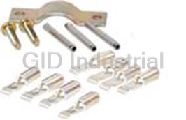
Cable Clamps and Clips Clamp Screw Steel Bulk
115G3-BK
Part Number
115G3-BK
Price
Request Quote
Manufacturer
ANDERSON POWER PRODUCTS
Lead Time
Request Quote
Category
Wire and Cables » Cable Clamps and Clips
Specifications
Manufacturer
Anderson Power Products
Manufacturers Part #
115G3-BK
Lead Time
6 Week Lead Time
Industry Aliases
115G3-BK
Sub-Category
Cable Clamps and Clips
Selling Alternatives
115G3
Packaging
Bulk
Factory Pack Quantity
1
Datasheet

Extracted Text
® Powerpole Connectors ® PP15-45 series are the smallest Powerpole housings. They can - PP15 to PP45 : be used for wire-to-wire or wire-to-board applications. Wire sizes up to 55 Amps from #20 AWG (0.75 mm²) to #10 (6 mm²) offer power capabilities up to 55 amps per pole. Finger proof housings and the ability to incorporate first-mate last-break ground connectors enhance the ® capabilities of this Powerpole series. High Power Density • Up to 55 amps in a compact footprint Wire-to Wire & Wire-to-Board Configurations • Wire & PCB contacts can be used in the same housings Finger Proof Housings Available • Protects against accidental contact with live circuits | PP15-45 ORDERING INFORMATION | PP15-45 Finger Proof Housings PP15-45 Finger Proof & Standard & Ground Improved on the original APP design by adding ribs to mating interface to Housing Dimensions protect against accidental contact with live circuits. Meets the requirements of UL1977 section 10.2 and is rated IP20. Will not mate with standard housings. Front View [ 7.9 ] 0.31 Description ------------ Part Numbers ------------ Mated Length [ 24.6 ] Finger Proof 0.97 Minimum Quantity ... 2,500 200 ..... Rib Feature Red 1327FP-BK 1327FP [ 7.9 ] [ 8.4 ] Green 1327G5FP-BK 1327G5FP 0.31 0.33 Black 1327G6FP-BK 1327G6FP [ 41.2 ] White 1327G7FP-BK 1327G7FP 1.62 Blue 1327G8FP-BK 1327G8FP Yellow 1327G16FP-BK 1327G16FP PP15-45 Standard Housings This original housing design has an open interface and is available in a wide array of colors. Will not mate with finger proof housings. Description ------- Part Numbers ------ Minimum Quantity ... 2,500 200 ... Red 1327-BK 1327 Green 1327G5-BK 1327G5 Black 1327G6-BK 1327G6 White 1327G7-BK 1327G7 Blue 1327G8-BK 1327G8 Yellow 1327G16-BK 1327G16 Orange 1327G17-BK 1327G17 Gray 1327G18-BK 1327G18 Brown 1327G21-BK 1327G21 Pink 1327G22-BK 1327G22 Purple 1327G23-BK 1327G23 45A Premate Ground Housings - (for use with ground contacts only) Green housings are keyed to prevent accidental mating with ® standard or finger proof Powerpole housings. Description ------ Part Numbers ----- Minimum Quantity ... 2,500 200 ... Green 1827G1-BK 1827G1 © 2018 Anderson Power Products, Inc. All rights reserved. APP®, Anderson Power Products®, A®, Powerpole®, SPEC Pak® and the APP Logo are registered trademarks of Anderson Power Products, Inc. - 20 - All Data Subject To Change Without Notice www.andersonpower.com SECTION 2 ® Powerpole PP15 to 45 SECTION 2 ® Powerpole PP15 to 45 PP15-45 Tin Plated Power Contacts Open Barrel Contact Offer cost effective performance up to 1,500 mating cycles. See specifications and temperature charts for amperage ratings by wire size. Dimensions [ 3.6 ] [ 3.6 ] 0.14 Mating Loose Piece Reeled - A - 0.14 Barrel AWG mm² Force -------- Part Numbers ------- inches mm [ 17.2 ] Minimum Quantity ....................................... 200 5,000 ......................... [ 6.4 ] 0.68 Open 14 to 10 K* 2.1 to 5.3 High 269G3-LPBK 269G3 0.21 5.33 0.25 Open 14 to 10 K* 2.1 to 5.3 Low 261G2-LPBK 261G2 0.20 5.08 Open 14 to 10 SF* 2.1 to 6.0 High 201G1H-LPBK 201G1H 0.24 6.10 A Open 14 to 10 SF* 2.1 to 6.0 Low 200G1L-LPBK 200G1L 0.24 6.10 Open 16 to 12 1.3 to 3.3 High 269G1-LPBK 269G1 0.18 4.57 Open 16 to 12 1.3 to 3.3 Low 261G1-LPBK 261G1 0.18 4.57 Open 20 to 16 0.52 to 1.3 High 269G2-LPBK 269G2 0.16 4.06 Open 20 to 16 0.52 to 1.3 Low 262G1-LPBK 262G1 0.16 4.06 K* - For #10 AWG class K stranded wire or smaller. For larger wires use superflex contacts. SF*- Indicates wires with high stranding such as Super Flex. PP15-45 Silver Plated Power Contacts Open Barrel Contact Maximize performance by offering up to 10,000 mating cycles and are recommended for circuit interrupt or hot plug applications. See specifications and temperature charts for amperage ratings by wire size. Only closed [ 17.27 ] [ 6.35 ] barrel contacts are suitable for soldering. 0.68 0.25 Dimensions Mating Loose Piece Reeled - A - - B - [ 3.81 ] A 0.15 Barrel AWG mm² Force ------- Part Numbers -------- Part Numbers inches mm inches mm Minimum Quantity .......................................... 5,000 200 5,000 ................................................. Open 14 to 10 K* 2.1 to 5.3 Low - 261G3-LPBK 261G3 0.20 5.08 - - Open 14 to 10 SF* 2.1 to 6.0 Low - 200G3L-LPBK 200G3L 0.24 6.10 - - Closed Barrel Contact Open 20 to 16 0.52 to 1.3 Low - 262G2-LPBK 262G2 0.16 4.06 - - Closed 16 to 12 1.3 to 3.3 Low 1331-BK 1331 - 0.15 3.81 0.10 2.54 [ 16.26 ] [ 7.35 ] Closed 20 to 16 0.52 to 1.3 Low 1332-BK 1332 - 0.12 3.05 0.07 1.78 0.64 0.29 B K* - For #10 AWG class K stranded wire or smaller. For larger wires use superflex contacts. [ 3.81 ] A SF*- Indicates wires with high stranding such as Super Flex. 0.15 45A Premate Ground Wire Contacts - (for use with ground housing only) Tin or silver plated contacts are rated for ground or power. Hand tools are available for loose piece Open Barrel Premate Contact contacts. Reeled contacts can be used with high volume press and applicator tooling. Tin contacts are rated for up to 1,500 mating cycles. Silver contacts are rated up to 10,000 mating cycles. [ 3.6 ] [ 19.1 ] 0.14 0.75 Reeled [ 6.4 ] Mating Loose Piece Part 0.25 Type AWG mm² Force - Part Numbers - - Numbers - [ 6.1 ] Minimum Quantity ............................................. 200 5,000 ..... 0.24 Open, Tin 14 to 10 2.1 to 6.0 Low 1830G1-LPBK 1830G1 [ 6.1 ] Open, Silver 14 to 10 2.1 to 6.0 Low 1830G2-LPBK 1830G2 0.24 25A Right Angle PCB Contacts Tin Plated Suitable for right angle applications up to 25A per pole. Tin plating enhances solderability. Cannot be mixed with 45A PCB contacts. For mating with wire contacts only. Dimensions Mating Loose Piece - A - - B - Row Force ------- Part Numbers ------- inches mm inches mm A Minimum Quantity ... 1,000 100 ................................................... [ 9.9 ] Top Low 1377G1-BK 1377G1 0.59 14.80 1.52 38.60 0.39 High 1317G1-BK 1317G1 Bottom Low 1377G2-BK 1377G2 0.29 7.20 1.36 34.50 B High 1317G2-BK 1317G2 Top Low 1377G11-BK 1377G11 0.59 14.80 1.21 30.70 Use mounting staples with right angle contacts High 1317G11-BK 1317G11 (see accessories). Bottom Low 1377G12-BK 1377G12 0.29 7.20 1.01 25.70 See website for PCB layout drawing. High 1317G12-BK 1317G12 25A Vertical PCB Contacts Tin Plated For mating with wire contacts only. Suitable for vertical applications up to 25A per pole, tin plating enhances solderability. Dimensions Mating Loose Piece - A - Force ---------------- Part Numbers --------------- inches mm Minimum Quantity .... 1,000 100 ....................... Low 1377G3-BK 1377G3 2.22 56.40 [ 3.1 ] High 1317G3-BK 1317G3 2.22 56.40 0.12 A Low 1377G4-BK 1377G4 1.76 44.70 Housing end High 1317G4-BK 1317G4 1.76 44.70 Low 1377G13-BK 1377G13 1.17 29.70 High 1317G13-BK 1317G13 1.17 29.70 - 21 - All Data Subject To Change Without Notice www.andersonpower.com 45A Right Angle and Vertical PCB Contacts Tin Plated [ 36.5 ] Vertical Suitable for right angle or vertical applications up to 45A per pole. Tin plating 1.44 [ 28.6 ] enhances solderability. Right angle contacts cannot be mixed with 25A PCB 1.13 contacts. For mating with wire contacts only. [ 29.7 ] [ 5.8 ] [ 5.1 ] 1.17 [ 16.3 ] Loose Piece 0.23 0.20 REF 0.64 Description ----------- Part Numbers ----------- PP15/45 Housings [ 7.9 ] [ 7.9 ] Minimum Quantity ............. 1,000 100 .................... (1327 Series) 0.31 0.31 Vertical 3-5911P1 1335G1 TYP Right Angle Contact TYP Right Angle Bottom Row 3-5912P1 1336G1 Horizontal (bottom) Use mounting staples with right angle Cat.No. 1336G1 Right Angle Top Row 3-5913P1 1337G1 Right Angle Contact contacts (see accessories). Horizontal (top), Cat.No. 1337G1 45A Premate Ground PCB Contacts Right angle contacts are suitable for power or ground. Use to mate with 45A [ 45.3 ] [ 7.9 ] ground wire contacts. Tin plated contacts are rated up to 1,500 mating cycles. 1.78 0.31 TYP [ 41.2 ] [ 14.7 ] Can be used with other 45A PCB connectors in the bottom row. 1.62 [ 8.4 ] 0.578 0.33 TYP Mating Loose Piece [ 5.6 ] Pre-mate wire Force ------- Part Numbers ------- 0.22 connector [ 3.6 ] [ 7.9 ] Minimum Quantity ................... 1000 100 .... 0.14 0.31 [ 28.1 ] PCB, Bottom Row Low 3-5952P1 1836G1 1.11 Mated Pair | PP15-45 ULTRASONICALLY BONDED ASSEMBLIES | Assemblies feature housings that are ultrasonically welded to create a one piece connector unit using an APP special process. After welding, retaining pins are ® no longer required to secure the stacked housings to each other. This allows Powerpole 15-45 connectors to be used as a durable one piece connector header. Contact customer service for configurations not shown below. Single Row 1x2 Assemblies Housings with Housings with 45A Vertical 45A Right Angle Color & Type Circuit Description Housings Only PCB Contacts PCB Contacts Position Matrix Minimum Quantity ................................ 500 500 500 ..... 1 2 DC 2 Wire Standard Housings ASMPP30-1X2-RK ASMPV45-1X2-RK ASMPR45-1X2-RK RED / STD BLK / STD DC 2 Wire Reverse Standard Housings ASMPP30-1X2-KR ASMPV45-1X2-KR ASMPR45-1X2-KR BLK / STD RED / STD DC 2 Wire Finger Proof ASMFP30-1X2-RK ASMFV45-1X2-RK ASMFR45-1X2-RK RED / FP BLK / FP DC 2 Wire Finger Proof Reverse ASMFP30-1X2-KR ASMFV45-1X2-KR ASMFR45-1X2-KR BLK / FP RED / FP Single Row 1x3 Assemblies Housings with 45A Right Angle Color & Type Circuit Description Housings Only PCB Contacts Position Matrix Minimum Quantity ................................ 500 500 ..... 1 2 3 DC 2 Wire Finger Proof with Ground ASMFP30-1X3-KER ASMFR45-1X3-KER BLK / FP GRN / GND RED / FP AC Single Phase Finger Proof ASMFP30-1X3-KEW ASMFR45-1X3-KEW BLK / FP GRN / GND WHT / FP Two Row 2x1 Assemblies Housings with Housings with 45A Vertical 45A Right Angle Color & Type Circuit Description Housings Only PCB Contacts PCB Contacts Position Matrix Minimum Quantity ................................ 500 500 500 .... 1 2 DC 2 Wire Finger Proof ASMFP30-2X1-KR ASMFV45-2X1-KR ASMFR45-2X1-KR BLK / FP RED / FP DC 2 Wire Finger Proof Mate ASMFP30-2X1-RK ASMFV45-2X1-RK ASMFR45-2X1-RK RED / FP BLK / FP Two Row 2x2 Assemblies Housings with Housings with 45A Vertical 45A Right Angle Color & Type Circuit Description Housings Only PCB Contacts PCB Contacts Position Matrix Minimum Quantity ................................ 500 500 500 ..... 1 2 3 4 AC 3 Phase, 3 Wire Finger Proof ASMFP30-2X2-KRWE N/A N/A BLK / FP RED / FP WHT / FP GRN / GND AC 3 Phase, 3 Wire Finger Proof Mate ASMFP30-2X2-WEKR N/A ASMFR45-2X2-WEKR WHT / FP GRN / GND BLK / FP RED / FP 1 2 1 Hood Up 3 4 1 2 1 2 3 2 Single Row 1x2 Assembly Single Row 1x3 Assembly Two Row 2x1 Assembly Two Row 2x2 Assembly Type STD = Standard Housing FP = Finger Proof Housing GND = Ground Housing - 22 - All Data Subject To Change Without Notice www.andersonpower.com SECTION 2 ® Powerpole PP15 to 45 SECTION 2 ® Powerpole Pak ® Powerpole Pak Connectors - PP15 to PP45 ® Powerpole Pak connector shells enclose stacked groupings of PP15-45 sized housings in a durable black shell for a finished connector appearance and additional features. Inline, panel mount, and blindmate configurations Plug shell with latch are available. Plug shells offer the option of integral latches and strain relief to help secure your connection. Snap-in • Package Groupings of PP15-45 Connectors Provides a finished appearance while protecting the individual connectors with an outer shell Blindmate • Inline, Panel Mount, “T” or Blindmate Configurations Allows one connection system to meet multiple needs T-Pak Plug shell • Optional Latching and Strain Relief without latch Secures your connection and wires ® For environmentally sealed connector shells to hold Powerpole ® 15-180 connectors, see SPEC Pak product series on our website, www.andersonpower.com ® Powerpole housings and contacts are sold separately. ® | POWERPOLE PAK ORDERING INFORMATION | See page 20 for ordering information. Plug Shell without Latch Can mate inline with other plug shells with or without latches, or mate to a panel ® mount receptacle. For use with Powerpole wire connectors only. Cable Clamp [ 53.09 ] and Hardware Pak or Retaining Pins must be ordered separately. [ 21.59 ] 2.09 Dimensions 0.85 - A - A Description -------------- Part Numbers -------------- inches mm Minimum Quantity ... 1,000 500 25 ............................. [ 49.28 ] Black, 2-4 Poles 1461G1-BK - 1461G1 1.24 31.50 1.94 Retaining Pin Black, 5-6 Poles - 1461G2-BK 1461G2 1.56 39.62 Side View Top View Black, 7-8 Poles - 1461G3-BK 1461G3 1.87 47.50 NOTE: Retaining pins are used to secure and position ® Powerpole housings in one of three positions in plug shells. Max wire O.D. for 2-4 pole plug shells is 0.60 inches [15.2mm²]. Plug Shell with Latch For all other plug shells is 0.63 inches [ 16.0 mm²]. Can mate inline with other plug shells without latches, or mate to a panel mount receptacle. For use ® with Powerpole wire connectors only. Cable Clamp and Hardware Pak or Retaining Pins must be ordered seperately. Side View Dimensions [ 21.59 ] - B - - C - - D - 0.85 Description ------------- Part Numbers -------------- inches mm inches mm inches mm B Minimum Quantity ..... 1,000 500 25 ................................................................................ Black, 2-4 Poles 1460G1-BK - 1460G1 1.94 49.28 2.25 57.15 1.24 31.50 Black, 5-6 Poles - 1460G2-BK 1460G2 1.94 49.28 2.25 57.15 1.56 39.62 Top View Black, 7-8 Poles - 1460G3-BK 1460G3 1.94 49.28 2.25 57.15 1.87 47.50 C Black, 9-10 Poles - 1460G4-BK 1460G4 2.51 63.75 2.82 71.63 1.84 46.74 D Retaining Pin - 23 - All Data Subject To Change Without Notice www.andersonpower.com Plug Shell with Latch & Non-Conductive Strain Relief [ 21.5 ] ® New 2X3 Powerpole Pak offers an improved ergonomic shell for easier latch operation as 0.85 well as a plastic, non-conductive strain relief. The new strain relief can accommodate up to a 6 conductor #10 AWG cable. Can mate to a panel mount receptacle. For use with ® Powerpole wire connectors only. Cable Clamp and Hardware Pak or Retaining Pins [ 81.5 ] must be ordered separately. To be used with 115G23 cable clamp only. 3.21 [ 73.5 ] 2.90 Description -------- Part Numbers ------- Minimum Quantity .. 1,000 25 ... Black, 5-6 Poles 1460G23-BK 1460G23 NOTE: Max wire O.D. for 1460G23 is 0.80 inches [ 51.4 ] [ 26.1 ] [20.3 mm²]. 2.02 1.03 Snap-in Receptacle Shell Mate to plug shells with or without latches, or mate to another panel mount receptacle to create a bulkhead to ® bulkhead connection. For use with Powerpole wire or PCB connectors. Order the number of retaining pins for each receptacle as shown below separately. Number of Dimensions Knock Out Size Retaining Pins - E - - Width - [ 1.78 ] Description ---------------- Part Numbers ---------------- to Order inches mm inches mm [ 19.56 ] 0.07 Minimum Quantity ... 1,000 500 25 ............................................................................... [ 27.94 ] 0.77 Black, 2-4 Poles 1470G1-BK - 1470G1 1 1.50 38.10 1.25 31.75 1.10 Black, 5-6 Poles - 1470G2-BK 1470G2 2 1.88 47.75 1.62 41.15 E Black, 7-8 Poles - 1470G3-BK 1470G3 3 2.13 54.10 1.88 47.75 Black, 9-10 Poles - 1470G4-BK 1470G4 4 2.44 61.98 2.19 55.63 * Height = [25.4 mm] 1.0 in. Retaining Pin NOTE: Retaining pins are used to secure and ® position Powerpole housings in one of two Cable Clamp & Hardware Pak positions in receptacle shells. Includes cable clamp, 2 screws, and required amount of retaining pins for each configuration. Screw Head Cable Description Type Type ------------ Part Numbers ------------ Retaining Pin Minimum Quantity ................................... 1,000 500 25 ... 2-4 Poles Straight Slot Bundled 115G1-BK - 115G1 5-6 Poles Straight Slot Bundled 115G2-BK - 115G2 Cable Clamp 7-8 Poles Straight Slot Bundled 115G3-BK - 115G3 With Screws 9-10 Poles Straight Slot Bundled - 115G4-BK 115G4 2-4 Poles Philips Bundled 115G7-BK - 115G7 Plug Shell Without Latch Shown 5-6 Poles Philips Bundled 115G8-BK - 115G8 Shell, housing and contacts are sold separately. Cable Clamp & Hardware Pak Includes 2 cable clamp halves, 2 screws and 2 retaining pins. To be used with 1460G23 Plug Shell only. Screws Retaining Screw Head Cable Pins Description Type Type ------ Part Numbers ------ Minimum Quantity ............................…… 1,000 25 5-6 Poles Philips Bundled 115G23-BK 115G23 Clamp Retaining Pin Flexible Conduit Clamp & Hardware Pak Includes cable clamp, 2 screws, and need amount of retaining pins for each configuration. Conduit Clamp Description - Part Number - With Screws Minimum Quantity ...... 100 ...... 2-4 Poles 110G10 Plug Shell With Latch Shown Shell, housing and contacts are sold separately. Retaining Pin for Snap-in Receptacle Order the number of retaining pins for each receptacle shown in the Snap-in Receptacle Shell ordering information. Pins are also required for the plug side when the Cable Clamp & Hardware Pak is not ordered. Description ----- Part Number ------ Minimum Quantity ..... 1,000 100 ... Shell and housing are Retaining Pin 110G9-BK 110G9 sold separately. - 24 - All Data Subject To Change Without Notice www.andersonpower.com SECTION 2 ® Powerpole Pak SECTION 2 ® Powerpole Pak Blindmate Pak Connector [ 88.6 ] 3.49 [ 50.8 ] Ideal for panel to panel, bulkhead to bulkhead, or rack mount applications that require the [ 24.38 ] [ 36.7 ] [ 58.93 ] [ 76.4 ] 2.00 0.960 1.45 2.320 power connector to compensate for up to 0.45 in. [11.43 mm] of misalignment in either axis. 3.01 ® Eight positions can be filled with Powerpole 10-45 connectors. The receptacle side can be used with wire or PCB contacts. Hardware bag includes retaining pins. Description ---------- Part Numbers ---------- [47.24] [ 13.46 ] Minimum Quantity .................................................... 50 25 .......... [ 5.0 ] [ 38.6 ] [ 3.05 ] 1.860 0.530 2x4 Blindmate Plug Shell, Hardware & Pins - BMPP10-45P Ø 0.20 4 1.52 0.120 2x4 Blindmate Receptacle Shell, Hardware & Pins - BMPP10-45R 2x4 Blindmate Plug Shell BMHSG-P - Plug Outline Receptacle Outline 2x4 Blindmate Receptacle Shell BMHSG-R - Hardware Bag Plug Side - 110G50 [ 29.14 ] [ 30.2 ] Hardware Bag Receptacle Side - 110G51 1.147 1.19 [ 36.7 ] [ 0.64 ] [21.5] 1.45 0.025 0.85 [ 0.64 ] [4.4] 0.025 0.17 See our innovative MARC Connector that offers straight-on or rotational blindmate capability. MARC holds 6 PP15/45 power contacts and 2 PP15/45 premate ground contacts in a high temperature hous- ing. Visit our website, www.andersonpower.com to learn more. “T” Pak 2 Way Splitter ® The Powerpole “T” Pak connector is a 2 way electrical splitter that splits electrical current from one incoming circuit into two outgoing circuits. The standard configuration is pre-wired for AC 3 phase, 3 wire plus ground configurations. The “T” Pak can also be used for AC single phase plus ground or DC 2 wire plus ground applications by not using either the red or white power positions. “T” Pak is pre-wired from the factory allowing plug and play field installation of modular office and industrial equipment. UL recognition up to 20 amps and 600 volts is ® achieved when mating Powerpole Pak plugs with #12 AWG wire. [ 86.2 ] For OEM manufacturing scale applications, the “T” Pak can be loaded with custom 3.39 [ 102.2 ] configurations of any of our finger proof, standard, or ground housings and contacts 4.03 in the PP15-45 series. Contact sales or customer service for additional information. Description - Part Numbers - [ 85.8 ] Minimum Quantity ............................ 80 ........ 3.38 Assembled “T” Pak 20-01 [ 53 ] Mating Plug Shell with Latch 2x2 26-01 2.09 Mating Plug Shell without Latch 2x2 27-01 [ 43.2 ] Standard configuration for each side of the T includes (1) each Red, Black, and White Standard 1.70 PP 15-45 Housings & 261G2-LPBK contacts with (1) 45A Green Premate Ground Housing and [ 51.1 ] 1830G1-LPBK contact. 2.01 Mating plug shells include (1) each Red, Black, and White Standard PP 15-45 Housings & (3) 261G2-LPBK contacts with (1) 45A Green Premate Ground Housing and 1830G1-LPBK contact. Cable clamp & hardware pak also included. A 27 - 01 26 - 01 Mates With B Mates With A & C C B - 25 - All Data Subject To Change Without Notice www.andersonpower.com ® | PP15-45 & POWERPOLE PAK SPECIFICATIONS | Mechanical Electrical Wire Size Range AWG mm² Current Rating Amperes ¹ UL 1977 CSA/TUV 20 to 10 0.75 to 6.0 Singlepole Wire to Wire (10 AWG) 55 40 Singlepole Ground Wire to Wire or PCB (10 AWG) 45 35 3x3 Block Wire to Wire (10 AWG) 40 27 Max. Wire Insulation Diameter in. mm Singlepole 25A PCB to Wire (12 AWG) 25 - 0.175 4.450 2x3 Block 25A PCB to Wire (12 AWG) 25 22 * Singlepole 45A PCB to Wire (10 AWG) 45 40 * Operating Temperature ² °F °C 2x3 Block 45A PCB to Wire (10 AWG) 45 25 * ® ® Powerpole Housings & Powerpole Pak Shells -4° to 221° -20° to 105° Voltage Rating AC/DC Mating Cycles No Load by Plating Silver (Ag) Tin (Sn) UL 1977 600 PCB to Wire - 1,500 Wire to Wire 10,000 1,500 Dielectric Withstanding Voltage Volts AC 2,200 Avg. Mating / Unmating Force Lbf. N Low Force Wire, High Force PCB, & Ground 3 13 Avg. Mated Contact Resistance Milliohms ¹ High Force Wire 5 22 15A Wire Contact with 5/8” of #16 AWG 0.875 Low Force PCB 2 9 30A Wire Contact with 5/8” of #12 AWG 0.600 45A Wire Contact with 5/8” of #10 AWG 0.525 45A PCB Contact to Contact 0.500 Min. Contact / Spring Retention Force Lbf. N 25A PCB Contact to Contact 0.600 20 90 5 ® UL Hot Plug Current Rating Amperes Powerpole Pak Latch Avg. Defeat Force Lbf. N 250 cycles at 72V DC 45A 150 667 250 cycles at 120V DC 30A PCB Specifications UL Ground Short Time Current Test - 45A Premate Ground Mounting Style Plated Through Hole 750 Amps, #10 AWG Wire 4 Seconds PCB Thickness- in. [mm] 0.090 - 0.150 (2.3-3.8) 470 Amps, #12 AWG Wire 4 Seconds 25A PCB Recommended Traces #12 AWG Cross Section 45A PCB Recommended Traces #10 AWG Cross Section Materials 4 Mechanical Shock Housing MIL-STD-202 213 Condition A 50g’s Plastic Resin Polycarbonate Contact Retention Spring Stainless Steel 4 Vibration High Frequency MIL-STD-202 204 Condition A 10g’s Housing Flammability Rating UL94 V-0 Glow Wire 825°C (GWFI) / 800°C (GWIT) Contact Base Copper Alloy Plating Tin or Silver Contact Termination Methods Crimp ³ Wire Contacts Hand Solder 1331, 1332 & PCB Contacts Solder Dip PCB Contacts Wave Solder PCB Contacts NOTE 1: See IEC 60664-1 for working voltage. NOTE 2: Amp ratings are stated per position and based on all positions being fully loaded. * No TUV Recognition 1 Based on: 105°C rated or better cable of the largest size, Properly calibrated APP recommended tooling, and a 25°C ambient temperature. UL rating not to exceed the maximum operating temperature. CSA rating below a 30°C temperature rise. 2 Limited by the thermal properties of the connector plastic housing. 3 Use APP recommended tooling only. Alternate tools may adversely affect the performance of our connectors along with UL and CSA recognition. 4 Tested with contact part number 261G2. 5 Based on 2 housings blocked together. - 26 - All Data Subject To Change Without Notice www.andersonpower.com SECTION 2 SECTION 2 ® ® Powerpole Powerpole PP15 to 45 Pak SECTION 2 SECTION 2 ® ® Powerpole Powerpole Pak PP15 to 45 | IEC INFORMATION | Creepage / Creepage / Connector Connector Material Material Clearance Clearance Series Series Configurations Group Configurations Group per IEC 60950-1 per IEC 60950-1 Unmated 1.64 mm Unmated 1.64 mm Single Pole Single Pole Mated 1.64 mm Mated 4.20 mm Unmated 1.64 mm Unmated 1.64 mm ® ® Stacked Powerpole Stacked Powerpole PP15/45 PP15/45 IIIa IIIa Mated 1.64 mm Mated 4.20 mm Standard Finger Proof Unmated 1.64 mm Unmated 1.64 mm PCB - 25A PCB - 25A Mated 1.64 mm Mated 2.90 mm Unmated 1.39 mm Unmated 1.39 mm PCB - 45A PCB - 45A Mated 1.39 mm Mated 1.39 mm Attributes * PP45 PP45 FP AMP Rating AC/DC 45 45 Amp Voltage Rating AC/DC (Steady State) 160 V AC/DC ( Operational) 400 V AC/DC ( Operational) Breaking Capacity -AMP Rating /Cycles 30 Amp / 10 Cycles 30 Amp / 10 Cycles Voltage Rating (Breaking Capacity) 220 VDC 220 VDC FINGER Safety - Mated only IEC 60529 - IP20 IEC 60529 - IP20 * Wire Size tested 6 mm² 6 mm² (10AWG) Contact Series Tested 200G3L 200G3L Climatic Testing (Cold,Heat & MFG) IEC 60512 Test -11j, 11i & 11g, IEC 60512 Test -11j, 11i & 11g Cycle Life IEC 60512 Test 9a - 5000 Cycles IEC 60512 Test 9a - 5000 Cycles Mechanical Strength Impact IEC 60512-5 @ 29.5 Inches - dropped 8 times IEC 60512-5 @ 29.5 Inches - dropped 8 times Temperature Range -20 °C to 105 °C -20 °C to 105 °C -4 °F to 221 °F -4 °F to 221 °F * Inmated and unmated condition Protection Touch Safety with Finger Proof Housings & Wire Contacts or PCB Mating Interface UL1977 Sec. 10.2 Pass IEC 60950 Pass IEC 60529 IP20 Touch Safety With Standard Housings IEC 60529 IP10 NOTE 3: Refer to the Constructional Data form for additional information on our website., www.andersonpower.com - 27 - All Data Subject To Change Without Notice www.andersonpower.com | PP15-45 TEMPERATURE CHARTS | Temperature rise charts are based on a 25°C ambient temperature. For Temperature Rise Above 60°C, Consult the Extended Temperature Rise Charts in the Appropriate Product Section on the Website. PP15-45 Multipole PP25 PCB PP15-45 Singlepole Temperature Rise at Constant Current Temperature Rise at Constant Current Temperature Rise at Constant Current 60 60 60 50 50 50 40 40 40 30 30 30 20 20 20 10 10 10 0 0 0 0 10 20 30 40 0 5 10 15 20 25 30 35 40 0 10 20 30 40 50 60 Amperes Applied Amperes Applied Amperes Applied 10 AWG 12 AWG 14 AWG 10 AWG 12 AWG 14 AWG Singlepole 2-Pole Multipole 16 AWG 18 AWG 20 AWG 16 AWG 18 AWG 20 AWG Current - Temperature Derating per IEC 60512-5-2 Test 5B PP15-45 Singlepole PP15-45 Multipole PP25 PCB Derating vs. Ambient Temperature Derating vs. Ambient Temperature Derating vs. Ambient Temperature 125 125 125 100 100 100 75 75 75 50 50 50 25 25 25 0 10 20 30 40 50 60 70 0 5 10 15 20 25 30 35 40 0 10 20 30 40 50 Amperes Applied Amperes Applied Amperes Applied 10 AWG 12 AWG 14 AWG Singlepole 2-Pole Multipole 10 AWG 12 AWG 14 AWG 16 AWG 18 AWG 20 AWG 16 AWG 18 AWG 20 AWG For Temperature Rise Above 60°C, Consult the Extended Temperature Rise Charts in the Appropriate Product Section on the Website. Current - Temperature Derating per IEC 60512-5-2 Test 5B PP45 PCB PP45 PCB Temperature Rise at Constant Current Derating vs. Ambient Temperature 60 125 50 100 40 30 75 20 50 10 0 25 0 10 20 30 40 50 60 0 10 20 30 40 50 60 70 Amperes Applied Amperes Applied Singlepole 2-Pole Multipole Singlepole 2-Pole Multipole NOTE: PP25 PCB charts based on 0.002 in² foil on board side, mated to #12 AWG conductor on wire side. PP45 PCB charts based on #10 AWG equivalent copper foil on board side, mated to #10 AWG conductor on wire side. - 28 - All Data Subject To Change Without Notice www.andersonpower.com SECTION 2 ® Powerpole PP15 to 45 Temperature Rise Ambient Temperature (°C) Temperature Rise Above Ambient (°C) Above Ambient (°C) Temperature Rise Ambient Temperature (°C) Above Ambient (°C) Ambient Temperature (°C) Temperature Rise Ambient Temperature (°C) Above Ambient (°C) SECTION 2 ® Powerpole PP15 to 45 ® | POWERPOLE 15-45 ACCESSORIES | Mounting Wing ® Secure dovetailed Powerpole 15-45 series housings by passing fasteners through the wings in either a horizontal or vertical orientation. Useful for sheet metal panels, printed circuit boards, and many other mounting surfaces. Fasteners not included. Mounting Wings Description ------- Part Numbers ------- [ 4.6 ] Minimum Quantity ... 2,500 100 .... 0.18 SQ Red 1399G9-BK 1399G9 [ 7.9 ] Blue 1399G8-BK 1399G8 0.31 [ 16.7 ] 0.66 Spacer Used to separate housings under high power to minimize derating. They are ® recommended for squaring off a block of Powerpole 15-45 housings for use in connector shells and mounting clamps. Use a combination of long and short spacers opposite each other in a mated block to add keying features or use two short spacers to avoid interference. Spacers with holes can also be used to fasten the blocked housings to a surface with a fastener. Description ------ Part Numbers ------- Minimum Quantity ..... 2,500 100 ..... Red, Short w/ Hole 1399G1-BK 1399G1 Red, Long 1399G2-BK 1399G2 [ 7.9 ] Red, Short 1399G6-BK 1399G6 [ 7.9 ] [ 7.9 ] 0.312 0.312 Black, Long 1399G10-BK 1399G10 0.312 Blue, Short 1399G13-BK 1399G13 [ 24.6 ] [ 16.6 ] [ 16.6 ] White, Short w/ Hole 1399G14-BK 1399G14 0.968 0.655 0.655 White, Long 1399G17-BK 1399G17 Short with Hole Short without Hole Long Retaining Pins ® Keep stacked Powerpole 15-45 series housings from separating. Retaining pins are inserted in the circular opening between two housings stacked side by side. Dimensions - A - - B - Description ----- Part Numbers ----- inches mm inches mm Minimum Quantity ... 1,000 100 ............................................................................ 1 Block High H1507P38 110G16 0.093 / 0.103 2.360 / 2.62 0.250 6.350 2 Block High 111812P5 110G17 0.093 / 0.103 2.360 / 2.62 0.440 11.180 B A Mounting Clamp ® Mounting clamps can be used for fastening a block of Powerpole 15-45 series housings to a panel. Connector blocks must be a complete square for the clamps to work properly. Fastening hardware not included. Description -- Part Numbers -- Minimum Quantity ... 100 sets of 2 ..... 2 or 4 Pole 1462G1 3 or 6 Pole 1462G2 4 or 8 Pole 1462G3 2 or 4 Pole 3 or 6 Pole 4 or 8 Pole - 29 - All Data Subject To Change Without Notice www.andersonpower.com PCB Mounting Staples ® PCB staples are soldered into place to secure Powerpole 15-45 series housings in a horizontal configuration to the board. Reduce strain on soldering joints during mating and unmating. Dimensions A Part - A - - B - Numbers H x W Length inches mm inches mm Minimum Quantity 100 ................................................................................ 114555P1 1 x 1 Short 0.47 12.0 0.28 7.0 B 114555P2 1 x 2 Short 0.47 12.0 0.57 14.5 114555P3 1 x 3 Short 0.47 12.0 0.89 22.5 114555P7 1 x 4 Short 0.47 12.0 1.20 30.5 114555P10 2 x 1 Short 0.79 20.0 0.28 7.0 114555P6 2 x 2 Short 0.79 20.0 0.57 14.5 114555P9 2 x 2 Long 0.91 23.0 0.57 14.5 Retention Clip ® Retention clips prevent Powerpole 15-45 blocks from unintended disconnects. They feature a tab for easy insertion and removal. Description -- Part Number -- Minimum Quantity ........ 100 ......... 1 Block High 110G68 Block Lok ® Block locks secure mated Powerpole 15-45 series housings together. For use in high vibration or shock applications where connectors are unmated infrequently. Description - Part Numbers - Minimum Quantity .......... 100 ......... 2 Pole 4 Pole 2 Pole, Black 110G21 4 Pole, Black 110G12 Shown without Powerpoles Shown with Powerpoles Splash Boot ® Splash boots protect a 2x2 block of any combination of Powerpole 15-45 series housings and feature snip off sealed ends for flexibility in wire O.D. Designed for through panel or inline applications. Not a hermetic seal. Description - Part Numbers - Minimum Quantity ........ 25 ........... Female, Black 1441G1 Male, Black 1442G1 ® For environmentally sealed connector shells to hold Powerpole ® 15-180 connectors, see SPEC Pak product series on our website, www.andersonpower.com - 30 - All Data Subject To Change Without Notice www.andersonpower.com 2018-0054 DS-PP1545 REV C6 SECTION 2 ® Powerpole PP15 to 45 SECTION 2 ® Powerpole Tooling ® Powerpole - Tooling Information Wire Size Reeled Part Numbers Reeled Contact Crimp Tool Tin Silver APP AWG mm² Plating Plating APP Press Applicator PP15 / 45 Flat Wiping Power & Ground #16 / 20 1.3 / 0.52 262G1 262G2 #16 / 20 1.3 / 0.52 269G2 N/A #12 / 16 3.3 / 1.3 261G1 N/A TD0101 #10 / 14 5.3 / 2.1 261G2 261G3 115V= TE0101 #12 / 16 3.3 / 1.3 269G1 N/A 230V = TE0102 #10 / 14 5.3 / 2.1 269G3 N/A #10 / 14 5.3 / 2.1 200G1L 200G3L #10 / 14 5.3 / 2.1 201G1H N/A TD0102 #10 / 14 5.3 / 2.1 1830G1 1830G2 NOTE: Insertion / Extraction tool for PP15/45 contacts = 111038G2 * APP applicators are mechanical feed style and do not require an air feed kit. Wire Size Loose Piece Part Numbers Loose Piece Contact Crimp Tool Pneumatic Tin Silver Hand Bench Number AWG mm² Plating Plating Tool or Tool + Die + Locator of Crimps or PP15 / 45 Flat Wiping Power & Ground #16 / 20 1.3 / 0.52 N/A 1332 1309G2 #12 / 16 N/A 3.3 / 1.3 1331 or #16 / 20 1.3 / 0.52 262G1-LPBK 262G2-LPBK 1309G8 1.3 / 0.52 #16 / 20 269G2-LPBK N/A #12 / 16 3.3 / 1.3 261G1-LPBK N/A 1309G3 N/A N/A N/A Single #10 / 14 5.3 / 2.1 261G2-LPBK 261G3-LPBK or #12 / 16 3.3 / 1.3 269G1-LPBK N/A 1309G8 #10 / 14 5.3 / 2.1 269G3-LPBK N/A #10 / 14 5.3 / 2.1 200G1L-LPBK 200G3L-LPBK 1309G6 or #10 / 14 5.3 / 2.1 201G1H-LPBK N/A 1309G8 310 / 14 5.3 / 2.1 1830G1-LPBK 1830G2-LPBK PP75 1307 #6 13.3 1389G6 5900 1875G1 1388G6 1389G21 #8 8.4 5952 1389G6 1387G1 Single N/A 1309G4 1875G2 1389G21 #10 / 12 5.3 / 3.3 5953 1389G6 5915 1388G7 1389G21 1875G3 PP120 1/0 53.5 1323G2 1388G3 #1 42.4 1323G1 #2 33.6 N/A 1368 1387G1 1389G4 Single 1319 Series 1388G4 #4 21.2 1319G4 #6 13.3 1319G6 PP180 3/0 85 1328G2 1303G12 2/0 53.5 1328G1 1/0 53.5 1382 N/A 1368 1387G2 1303G13 1304G32 Double #1 42.4 1347 Series #2 33.6 1383 #4 21.1 1384 #6 13.3 1348 1387G1 1388G4 1389G3 Single 1. NOTE: See website for the most current information. 2. NOTE: Insertion / Extraction fool for PP15/45 contacts = 111038G2 - 47 - All Data Subject To Change Without Notice www.andersonpower.com
Frequently asked questions
How does Electronics Finder differ from its competitors?

Is there a warranty for the 115G3-BK?
Which carrier will Electronics Finder use to ship my parts?
Can I buy parts from Electronics Finder if I am outside the USA?
Which payment methods does Electronics Finder accept?
Why buy from GID?

Quality
We are industry veterans who take pride in our work

Protection
Avoid the dangers of risky trading in the gray market

Access
Our network of suppliers is ready and at your disposal

Savings
Maintain legacy systems to prevent costly downtime

Speed
Time is of the essence, and we are respectful of yours
Related Products
Powerpole Pak Connector 115G1
Cable Clamps and Clips Clamp Screw 115G1-BK
Cable Clamps and Clips Clamp Screw 115G2-BK
Cable Clamps and Clips Clamp Screw Steel 115G3
Cable Clamps and Clips Clamp Screw 115G7
Cable Clamps and Clips Clamp 945
Request a Quote

The quote request has been received
Close

Facing challenges or have inquiries? Feel free to contact us!
Call Us +1-469-283-2440
What they say about us
FANTASTIC RESOURCE
One of our top priorities is maintaining our business with precision, and we are constantly looking for affiliates that can help us achieve our goal. With the aid of GID Industrial, our obsolete product management has never been more efficient. They have been a great resource to our company, and have quickly become a go-to supplier on our list!
Bucher Emhart Glass
EXCELLENT SERVICE
With our strict fundamentals and high expectations, we were surprised when we came across GID Industrial and their competitive pricing. When we approached them with our issue, they were incredibly confident in being able to provide us with a seamless solution at the best price for us. GID Industrial quickly understood our needs and provided us with excellent service, as well as fully tested product to ensure what we received would be the right fit for our company.
Fuji
HARD TO FIND A BETTER PROVIDER
Our company provides services to aid in the manufacture of technological products, such as semiconductors and flat panel displays, and often searching for distributors of obsolete product we require can waste time and money. Finding GID Industrial proved to be a great asset to our company, with cost effective solutions and superior knowledge on all of their materials, it’d be hard to find a better provider of obsolete or hard to find products.
Applied Materials
CONSISTENTLY DELIVERS QUALITY SOLUTIONS
Over the years, the equipment used in our company becomes discontinued, but they’re still of great use to us and our customers. Once these products are no longer available through the manufacturer, finding a reliable, quick supplier is a necessity, and luckily for us, GID Industrial has provided the most trustworthy, quality solutions to our obsolete component needs.
Nidec Vamco
TERRIFIC RESOURCE
This company has been a terrific help to us (I work for Trican Well Service) in sourcing the Micron Ram Memory we needed for our Siemens computers. Great service! And great pricing! I know when the product is shipping and when it will arrive, all the way through the ordering process.
Trican Well Service
GO TO SOURCE
When I can't find an obsolete part, I first call GID and they'll come up with my parts every time. Great customer service and follow up as well. Scott emails me from time to time to touch base and see if we're having trouble finding something.....which is often with our 25 yr old equipment.
ConAgra Foods