

 Manufacturers
ARTESYN PSE1000DCDC-12V

Description
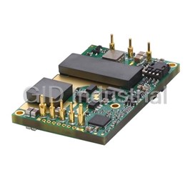
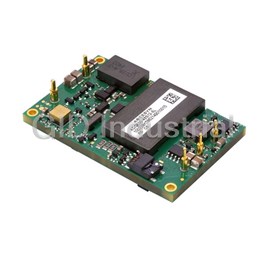
1000 W, 370 -400 VDC Vin, Single Output, 12 VDC@83.3 A DC-DC Converter
Part Number
PSE1000DCDC-12V
Price
Request Quote
Manufacturer
ARTESYN
Lead Time
Request Quote
Category
Capacitors » DC-DC Converter
Specifications
Manufacturer
Artesyn
Manufacturers Part #
PSE1000DCDC-12V
Brand
Artesyn Embedded Technologies
Series
PSE1000DCDC-12V
Factory Pack Quantity
1
Dimensions
4.80 x 2.40 x 1.00"
Efficiency
94%
Input Voltage Nominal
390 VDC
Isolation
5700 VDC
Mechanical Style
Isolated
Mounting
Through Hole
Number of Outputs
1
Operating Temperature
- 40 to + 85°C
Output Amps 1
83.3 A
Output Voltage V1 Nominal
12 VDC
Power
1000 W
Subcategory
DC-DC Converter
Datasheet

Extracted Text
Technical Reference Note Rev.03.25.15_#1.1 PSE1000PFC Series Page 1 PSE1000PFC 1100 Watts PFC Front End Total Power: 1100 Watts #of Outputs: Single Output: 390Vdc Special Features • 1100 W output power Product Descriptions • Unity power factor correction The PSE1000PFC Power Factor Correction module is part of advanced High • 3.5”x2.4”x1” Density modular power supply components. Featuring high reliability and • 119 Watts per cubic inch convenient control and monitoring functions, these modules are designed to • Industrial Safety O O O O r re ed du uc ce e p pr ro od du uc ctt d de ev ve ello op pm me en ntt ttiim me e a an nd d e en nh ha an nc ce e s sy ys stte em m p pe er rffo or rm ma an nc ce e.. T Th he e P PF FC C • • - -4 40 0 C C tto o 8 85 5 C C module is designed to work over all typical line voltages used worldwide, and • High efficiency: 94% typical provide unity power factor with very low levels of harmonic distortion in line • Negative enable function current. • Output OTP,OVP and power limit • MIL-STD-810F for shock and vibration • Current sharing and monitoring Compliance • EMI Class B (with external EMI filter) • EN61000 Immunity (with external EMI filter) • RoHS 2 Safety • UL 60950-1 508/1598/1433 60601-1 ed 3 • cUL 60950-1 • TUV 60950-1 60601 • CB Scheme Report/Cert T Te ec ch hn niic ca all R Re ef fe er re en nc ce e N No ot te e Rev.03.25.15_#1.1 PSE1000PFC Series Page 2 Model Number Maximum Output Minimum Maximum Output Model Continuous 1 2 4 Voltage Load Load Ripple P/P Safety Approval 3 Number Power o (V) (A) (A) @ 0-50 C (P ) O,max PSE1000PFC 390 0 2.82 <50V 1100W See Note 4 below Note 1 - Load will be controlled by LD_EN signal for all input conditions. Load will be loaded when LD_EN is high, and load will be removed when LD_EN is low. The load current ramp will be no more than 1A/us. Note 2 - Output ripple measured at the end of the output cable terminated with 10uF aluminum electrolysis cap in parallel with 0.1uF ceramic capacitor. Note 3 - The maximum continuous average output power from this power supply shall be 1100W. Note 4 - Safety Approvals: (A) UL+cUL 60950-1 (B) UL 60601-1 (C) TUV 60950-1 (D) TUV 60601 (E) CB Scheme Report/Cert Options None Artesyn Embedded Technologies T Te ec ch hn niic ca all R Re ef fe er re en nc ce e N No ot te e Rev.03.25.15_#1.1 PSE1000PFC Series Page 3 Electrical Specifications Absolute Maximum Ratings Stress in excess of those listed in the ‘Absolute Maximum Ratings’ may cause permanent damage to the power supply. These are stress ratings only and functional operation of the unit is not implied at these or any other conditions above those given in the operational sections of this TRN. Exposure to any absolute maximum rated condition for extended periods may adversely affect the power supply’s reliability. Table 1. Absolute Maximum Ratings: Parameter Model Symbol Min Typ Max Unit Input Voltage: PSE1000PFC AC continuous operation V 90 - 264 Vac IN,AC Maximum Output Power PSE1000PFC P - - 1100 W O,max Isolation Voltage: PSE1000PFC Input to Chassis - - 1500 Vac 1 2 O Operating Temperature PSE1000PFC T -40 - +85 C A 3 3 3 3 O O S Stto or ra ag ge e T Te em mp pe er ra attu ur re e P PS SE E1 10 00 00 0P PF FC C T T - -4 40 0 - - + +1 10 00 0 C C STG Humidity Operating (Non-condensing) PSE1000PFC 10 - 100 % Non-operating (Condensing) 10 - 100 % Altitude 4 Operating PSE1000PFC -500 - 13,000 feet Storage -1000 - 50,000 feet Note 1 - Ambient Temperature at full load O O Note 2 - Baseplate Temperature at full load (Output derating applies from 85 C to 100 C Baseplate Temperature operation) O Baseplate temperature is average temperature of the five measure points shows right. The supply could work at -40 C ambient O temperature for all input conditions. The supply could work at up to 85 C baseplate temperature for Vin≥100Vac. For input voltage is O lower than 100Vac, the supply could work at 85 C with no more than 1000W output power. Note 3 - Ambient Temperature is the same with Baseplate Temperature o Note 4 - Derating 1 C Per 1000 feet above 10,000 feet. Artesyn Embedded Technologies T Te ec ch hn niic ca all R Re ef fe er re en nc ce e N No ot te e Rev.03.25.15_#1.1 PSE1000PFC Series Page 4 Input Specifications Table 2. Input Specifications: Parameter Conditions Symbol Min Typ Max Unit Operating Input Voltage, AC All V 90 115/230 264 Vac IAC RMS Input Vac Source Frequency All f 47 50/60 63 Hz IAC Maximum Input Current V = 90V I - - 13 A IAC AC I,max RMS (I = I ) O O, max No Load Input Current V = 90V I - - 200 mA I,no_load IAC AC RMS (V On, I = 0A) O O Nominal Input Harmonic Line Currents THD Per ANSI C82.11-1993. Conditions V = 115Vac/230Vac IAC 25% to 100% load PF 0.9 - - @47-63Hz Power Factor V = 120Vac IAC 100% load PF 0.97 - - @47-63Hz Startup Surge Current (Inrush) at 230Vac @ 25°C V = 230V - - - 50 A IAC AC PK (with external resistor from INRUSH pin to OUTPUT-) Isolation – Input to Chassis All - - 1500 - Vac V = 230V IAC AC Leakage Current to earth ground - - - 275 uA f = 50/60 Hz IAC PFC Switching Frequency All f 49 - 52 KHz SW,PFC I = I O O,max o Operating Efficiency @ 25 C η 94 - - % V =230V IAC AC V = 90Vac Turn On Delay: IN,AC I = I Resistive Load O O, t - - 2000 mSec max turn-On System Stability: Phase Margin - - 45 - - Ø Gain Margin 10 dB Artesyn Embedded Technologies T Te ec ch hn niic ca all R Re ef fe er re en nc ce e N No ot te e Rev.03.25.15_#1.1 PSE1000PFC Series Page 5 Output Specifications Table 3. Output Specifications: Parameter Condition Symbol Min Typ Max Unit Inclusive of set-point, temperature change, Output Regulation V 380 390 400 V O warm-up drift and dynamic load Output Power All Po - - 1100 W Measure with a 0.1uF ceramic capacitor in Output Ripple, pk-pk parallel with a 10uF Vo - - 50 V PK-PK tantalum capacitor, 0 to 20MHz bandwidth Output Current All I 0 - 2.82 A O 1 V Load Capacitance Start up 330 680 1000 uF O V Dynamic Response O 50% load change, P Pe ea ak k D De ev viia attiio on n ± ±% %V V - - - - 5 5 % % O O slew rate = 1A/us Settling Time T - - 500 uSec s V Long Term Stability After thermal O ±%V - - 1 % O equilibrium (30 mins) Max change over 24 hours Input:115Vac/50Hz, Output:390V/2.82A, Measure with 2 x Hold up time 16 - - ms 330uF/450V bulk capacitors across the DC output. Note 1 - Unless otherwise specified, all of the outputs will have 680uF/450V electrolytic capacitor. Artesyn Embedded Technologies T Te ec ch hn niic ca all R Re ef fe er re en nc ce e N No ot te e Rev.03.25.15_#1.1 PSE1000PFC Series Page 6 System Timing Specifications Table 4. System Timing Specifications: Label Parameter Min Typ Max Unit T1 Delay from AC being applied to V being within regulation - - 1000 mSec o T2 V rise time, 0V to V in regulation. 5 - 50 mSec o o Delay from AC being applied to output voltages being within T3 - - 2000 mSec regulation with LD_EN asserted high. Hold up time - time all voltages stay within regulation after loss of T4 16 - - mSec AC. T5 Delay from loss of AC to de-assertion of LD_EN. 11 - - mSec Delay from LD_EN de-asserted to output voltages T6 1 - - mSec dropping out of regulation limits. Artesyn Embedded Technologies T Te ec ch hn niic ca all R Re ef fe er re en nc ce e N No ot te e Rev.03.25.15_#1.1 PSE1000PFC Series Page 7 System Timing Specifications Figure 1. System Timing Diagram: Artesyn Embedded Technologies T Te ec ch hn niic ca all R Re ef fe er re en nc ce e N No ot te e Rev.03.25.15_#1.1 PSE1000PFC Series Page 8 PSE1000PFC Performance Curves Figure 1: PSE1000PFC Turn-on delay via AC mains – Vin = 90Vac Figure 2: PSE1000PFC Hold-up Time – Vin = 115Vac / 63Hz / 0°°°° Full Load: Io = 2.82A Full Load: Io = 2.82A (Measure with 2 x 330uF/450V Bulk Caps) Ch 1: AC Mains Ch 2: Vo Ch 1: AC Mains Ch 2: Vo Figure 3: PSE1000PFC Output Startup Characteristic – Vin = 90Vac Figure 4: PSE1000PFC Ripple and Noise Measurement – Vin = 90Vac Full Load: Io = 2.82A Full Load: Io = 2.82A Ch 1: Vo Ch 1: Vo Figure 5: PSE1000PFC Transient Response – Vo Deviation (low to high) Figure 6: PSE1000PFC Transient Response – Vo Deviation (high to low) 25% to 75% load change, 1A/uS slew rate, Vin = 230Vac 75% to 25% load change, 1A/uS slew rate, Vin = 230Vac Ch 1: Vo Ch 2: Io Ch 1: Vo Ch 2: Io Artesyn Embedded Technologies T Te ec ch hn niic ca all R Re ef fe er re en nc ce e N No ot te e Rev.03.25.15_#1.1 PSE1000PFC Series Page 9 PSE1000PFC Performance Curves 100 95 90 85 80 75 70 0 0.282 0.564 0.846 1.128 1.41 1.692 1.974 2.256 2.538 2.82 Output current Figure 7: PSE1000PFC Efficiency Curves @ 25 degC 90 Vac 115Vac 230Vac 264Vac Loading: Vo = 10% increment to 2.82A Artesyn Embedded Technologies Efficiency (%) T Te ec ch hn niic ca all R Re ef fe er re en nc ce e N No ot te e Rev.03.25.15_#1.1 PSE1000PFC Series Page 10 Protection Function Specification Over Voltage Protection (OVP) The overvoltage point is between 107% and 115% of typical output voltage 390V. The power supply latches off during output over voltage with the AC line recycled to reset the latch. Parameter Min Nom Max Unit Output Overvoltage 420 / 450 V Over Current Protection (OCP) The power supply PSE1000PFC includes internal current limit circuitry to prevent damage in the event of overload or short circuit. It should shut down in bouncing mode in case of the over current condition. Recovery is automatic when the overload is removed. The OCP range is defined shall be not exceed 160% of 1000W full load (2.56A) at any condition. Parameter Min Nom Max Unit Output Overcurrent 3.3 / 4.1 A Over Temperature Protection (OTP) O O The power supply is internally protected against over baseplate temperature (102 C – 107 C) conditions. The OTP O mode is shut down and automatically restart when fault is removed. The recover baseplate temperature is 92 C – 97 O C. No Load protection The power supply will not suffer damage if any or all outputs have no load. Artesyn Embedded Technologies T Te ec ch hn niic ca all R Re ef fe er re en nc ce e N No ot te e Rev.03.25.15_#1.1 PSE1000PFC Series Page 11 Mechanical Specifications Mechanical Outlines (unit:mm) Artesyn Embedded Technologies T Te ec ch hn niic ca all R Re ef fe er re en nc ce e N No ot te e Rev.03.25.15_#1.1 PSE1000PFC Series Page 12 Mechanical Specifications Mechanical Outlines (unit:mm) Artesyn Embedded Technologies T Te ec ch hn niic ca all R Re ef fe er re en nc ce e N No ot te e Rev.03.25.15_#1.1 PSE1000PFC Series Page 13 Mechanical Specifications Mechanical Outlines (unit:mm) Artesyn Embedded Technologies T Te ec ch hn niic ca all R Re ef fe er re en nc ce e N No ot te e Rev.03.25.15_#1.1 PSE1000PFC Series Page 14 Pin Definitions Table 5. Pin Definitions: Pin Length Diameter Designation Definitions L1 Line AC Input Pin L1 = 4.6 ± 0.5 mm Φ2.0±0.1 mm L2 Neutral INRUSH Limit Inrush Current OUTPUT+ DC Output+ DC Output Pin L2 = 4.6 ± 0.5 mm Φ2.0±0.1 mm OUTPUT- DC Output- S GND Signal Ground Control the relay out of the RELAY unit to short the inrush resistor C_MON Current monitoring For active load sharing C_SHARE when the units in parallel C Co on nttr ro oll P Piin n L L3 3 = = 3 3..8 8±± 0 0..5 5 m mm m Φ Φ1 1..1 1+ +0 0..1 15 5//- -0 0..0 00 0 m mm m D Diig giitta all c co om mm mu un niic ca attiio on n ffo or r TXD transmitting data to an external device Digital communication for RXD receiving data for the internal MCU LD_EN Load enable REMOTE Remote ON/OFF Artesyn Embedded Technologies T Te ec ch hn niic ca all R Re ef fe er re en nc ce e N No ot te e Rev.03.25.15_#1.1 PSE1000PFC Series Page 15 Weight The PSE1000PFC series weight is 0.88 pounds (0.4kg) maximum. Artesyn Embedded Technologies T Te ec ch hn niic ca all R Re ef fe er re en nc ce e N No ot te e Rev.03.25.15_#1.1 PSE1000PFC Series Page 16 Environmental Specifications EMC Immunity PSE1000PFC power supply (with external EMI filter) is designed to meet the following EMC immunity specifications: Table 6. Environmental Specifications: Document Description FCC Part 15 Subpart J Class B conducted and Class B with a ground plane for radiated interference(with 6db margin) VCCI Class II EN 61000-4-2 ESD up to 4KV contact, 8KV discharge, performance Criteria B EN 61000-4-3 RFI 3V/m EN 61000-4-4 Electrical Fast Transients level 3 minimum EN 61000-4-5 Surge level 3 minimum EN 61000-4-6 Radio frequency common mode, Levels 3V (rms) Modulated AM 80%. 1 k kH Hz z,, 1 15 50 0 o oh hm m s so ou ur rc ce e iim mp pr re es ss se ed d EN 61000-4-8 Power Frequency Magnetic Immunity, 1 A/m. EN 61000-4-11 AC Input transients [Reference EN 60601-1:2001] EN 61547 Specification for equipment for general lighting purposes/ EMC immunity requirements Artesyn Embedded Technologies T Te ec ch hn niic ca all R Re ef fe er re en nc ce e N No ot te e Rev.03.25.15_#1.1 PSE1000PFC Series Page 17 Safety Certifications The PSE1000PFC power supply is intended for inclusion in other equipment and the installer must ensure that it is in compliance with all the requirements of the end application. This product is only for inclusion by professional installers within other equipment and must not be operated as a stand alone product. Table 7. Safety Certifications for PSE1000PFC series power supply system Document Description UL+CUL: UL60950-1 2nd Ed; US and Canada Requirements Information Technology Equipment - Safety - Part 1: General Requirements (Bi- CSA C22.2 No. 60950-1-07, 2nd Ed National standard, with UL 60950-1) TUV or VDE/EN60950: IEC 60950-1:2005 (2nd Ed); Am1:2009, European Requirements EN 60950- 1:2006/A11:2009/A1:2010/A12:2011 CB Certificate and Report All CENELEC Countries CE mark: EN 60950-1/A12:2011 LVD+RoHS Artesyn Embedded Technologies T Te ec ch hn niic ca all R Re ef fe er re en nc ce e N No ot te e Rev.03.25.15_#1.1 PSE1000PFC Series Page 18 EMI Emissions The PSE1000PFC and PSE1000DCDC-12V series has been designed to comply with the Class B (with external EMI filter before PFC module) limits of EMI requirements of EN55022 (FCC Part 15) and CISPR 22 (EN55022) for emissions and relevant sections of EN61000 (IEC 61000) for immunity. The unit is enclosed inside a metal box, tested at PSE1000DCDC-12V DC/DC module 1000W output using resistive load. Conducted Emissions The applicable standard for conducted emissions is EN55022 (FCC Part 15). Conducted noise can appear as both differential mode and common mode noise currents. Differential mode noise is measured between the two input lines, with the major components occurring at the supply fundamental switching frequency and its harmonics. Common mode noise, a contributor to both radiated emissions and input conducted emissions, is measured between the input lines and system ground and can be broadband in nature. The PSE1000PFC and PSE1000DCDC-12V power supplies with external EMI filters before PSE1000PFC to ensure the convertors’ conducted EMI levels comply with EN55022 (FCC Part 15) Class B and EN55022 (CISPR 22) Class B limits. The EMI measurements are performed with resistive loads at maximum rated loading. S Sa am mp plle e o off E EN N5 55 50 02 22 2 C Co on nd du uc ctte ed d E EM MII M Me ea as su ur re em me en ntt a att 230Vac input Note - Blue Line refers to Emerson Quasi Peak margin, which is 6dB below the CISPR international limit. Red Line refers to the Emerson Average margin, which is 6dB below the CISPR international limit. Conducted Emissions Table 8. Conducted EMI emission specifications of the PSE1000PFC and PSE1000DCDC-12V series Parameter Model Symbol Min Typ Max Unit FCC Part 15, class B PSE1000PFC Margin - - 6 dB VCCI Class II PSE1000PFC Margin - - 6 dB CISPR 22 (EN55022) class B PSE1000PFC Margin - - 6 dB for conducted and class B for radiated (stand alone) CISPR 22, EN55022 class A PSE1000PFC Margin - - 6 dB (For DC-DC assemblies) Artesyn Embedded Technologies T Te ec ch hn niic ca all R Re ef fe er re en nc ce e N No ot te e Rev.03.25.15_#1.1 PSE1000PFC Series Page 19 Radiated Emissions Unlike conducted EMI, radiated EMI performance in a system environment may differ drastically from that in a stand-alone power supply. The shielding effect provided by the system enclosure may bring the EMI level from Class A to Class B. It is thus recommended that radiated EMI be evaluated in a system environment. The applicable standard is EN55022 Class A (FCC Part 15). Testing ac-dc convertors as a stand-alone component to the exact requirements of EN55022 can be difficult, because the standard calls for 1m leads to be attached to the input and outputs and aligned such as to maximize the disturbance. In such a set-up, it is possible to form a perfect dipole antenna that very few ac-dc convertors could pass. However, the standard also states that ‘an attempt should be made to maximize the disturbance consistent with the typical application by varying the configuration of the test sample. Artesyn Embedded Technologies T Te ec ch hn niic ca all R Re ef fe er re en nc ce e N No ot te e Rev.03.25.15_#1.1 PSE1000PFC Series Page 20 Storage and Shipping Temperature / Humidity O O The PSE1000PFC series power supplies can be stored or shipped at temperatures between -40 C to +85 C and relative humidity from 10% to 100% non-condensing. Altitude The PSE1000PFC series will operate within specifications at altitudes up to 13,000 feet (maximum) above sea level. The power supply shall not be damaged when stored at altitudes of up to 50,000 feet (maximum) above sea level. Humidity The PSE1000PFC series will operate within specifications when subjected to a relative humidity from 10% to 100% non- condensing. The PSE1000PFC series can be stored in a relative humidity from 10% to 100% non-condensing. Vibration The PSE1000PFC power supply will pass the following vibration specifications: (Per MIL-STD-810F 514.5, Cat, IEC68-2-6) Operating Random Vibration Acceleration 4.0 gRMS Frequency Range 8-500 Hz Sweep Rate 1 Oct/Min Duration 1 Mins No of Sweep 3 Sweep Direction 3 mutually perpendicular axis FREQ Level PSD Profile 8-200 Hz 2.0g 200-500 Hz 4.0g Artesyn Embedded Technologies T Te ec ch hn niic ca all R Re ef fe er re en nc ce e N No ot te e Rev.03.25.15_#1.1 PSE1000PFC Series Page 21 Shock The PSE1000PFC power supply will pass the following shock specifications:MIL-STD-810F 516.5, IEC 68-2-27, test Ea. The unit shall be subjected to three positive and three negative pulses in each axis while operational in the system. Each pulse shall be 30g, half sine and 11 msec duration. Operating Half-Sine Shock Acceleration 30 G Duration 11 msec Pulse Half-Sine No. of Shock 3 shock on each of 6 faces Artesyn Embedded Technologies T Te ec ch hn niic ca all R Re ef fe er re en nc ce e N No ot te e Rev.03.25.15_#1.1 PSE1000PFC Series Page 22 Power and Control Signal Descriptions AC Input Connector These connectors supply the AC Mains to the PSE1000PFC power supply. A power resistor of 10 to 90 Ohm of 10 watt or above (depending on the output capacitance) should be connected from the pin INRUSH to the -Vo output pin. An internal MOSFET bypasses this external thermistor/ resistor during normal operation INPUT L1 - Line INPUT L2 - Neutral INRUSH - Limit Inrush Current DC Output Connector The two connectors provide the main output for the PSE1000PFC. The OUTPUT “+” and the OUTPUT “-” pins are the positive and negative rails, respectively of the V output of the PSE1000PFC power supply. The Output (V ) connectors O O are electrically isolated from the power supply chassis. Bulk capacitors of minimum 2 x 330uF, 450V (or 1 x 680uF, 450V) is recommended be put across the DC output. OUTPUT+ - DC Output+ O OU UT TP PU UT T- - - - D DC C O Ou uttp pu utt R Re ettu ur rn n Output Connector - Control Signals The PSE1000PFC contains 8 pins control signal headers providing analogy control interface, Current Share and REMOTE interface. S GND (Signal Ground) The S GND pin is connected to the internal common ground of the module. It is also internally connected to the –OUTPUT terminal. When connecting S GND to external circuitry care must be taken to ensure that the current flowing through this pin is kept below 25mA. RELAY The RELAY is reservation pin to control the relay out of the unit to short the inrush resistor. But in this version unit, there are MOSFETs inside the model to short the inrush resistor. Artesyn Embedded Technologies T Te ec ch hn niic ca all R Re ef fe er re en nc ce e N No ot te e Rev.03.25.15_#1.1 PSE1000PFC Series Page 23 C_MON The C_MON is for current monitoring of PSE1000PFC. VIN(Vac) Frequency(Hz) Iout(A) C_MON Specs(V) 115 50 1.128 0.4+/-0.04 115 50 2.82 1.00+/-0.10 230 50 1.128 0.4+/-0.04 230 50 2.82 1.00+/-0.10 C_SHARE The main output shall have active load sharing. The output will be within 10% at full load. All current sharing functions are implemented internal to the power supply by making use of the C_SHARE signal. The system connects the C_SHARE lines between the power supplies. The supplies must be able to load share with up to 10 power supplies in parallel. TXD TXD is the serial output pin of the UART(Universal Asynchronous Receiver and Transmitter) digital communication. It’s used for transmitting data to an external device. RXD RXD is the serial input pin of the UART(Universal Asynchronous Receiver and Transmitter) digital communication. It’s used for receiving data for the internal MCU.The UART(Universal Asynchronous Receiver and Transmitter) digital communication of PSE1000PFC and computer can just be used to read particular data or variable such as Input Voltage, Input Current, Input Power, Output Voltage, Output Current, Primary Temperature and so on. It can’t be used to adjust the fixed parameter such as OCP,OVP and OTP point etc. Below setup shows the software communication of PSE1000PFC and computer. Note: Don’t connect PSE1000PFC to computer directly. Please isolate the PSE1000PFC and computer with communication ports with optocouplers. Artesyn Embedded Technologies T Te ec ch hn niic ca all R Re ef fe er re en nc ce e N No ot te e Rev.03.25.15_#1.1 PSE1000PFC Series Page 24 Below the Transaction Index Pointer indicates what particular data or variable will be transacted in the communication Transaction Index Pointer Description 0x03 Input Voltage Register 0x04 Input Current Register 0x05 Primary Temperature Register 0x06 Bulk Voltage Register 0x07 Input Power Register 0x08 Primary Temperature 2 Register 0x09 Output Current Register LD_EN PSE1000PFC is designed to power on at no load. After the PFC power up sequence, the power to the load can be enabled. This can be performed manually or the PFC can automatically enable the load using the LD_EN signal. The LD_EN is PFC Module Enable Output. This TTL compatible signal will go high when the soft start has been completed and output voltage is within regulation. Initially the load is disabled and the LD_EN is less than 0.4V (LOW). When the PFC power up sequence has completed, the LD_EN voltage goes HIGH to automatically enable the load. LD_EN low level: Less than 0.4V while sinking 5mA. LD_EN high level: Less than 100uA sourcing at 4-5V. REMOTE The REMOTE is for remote control of the PFC module. It is negative logic and TTL compatible signal, pull the pin to low to enable PFC. When pull Remote to low, the LD_EN will become high in one second. When set the Remote to high, the LD_EN will become low in 25ms. Remote Off Spec (ms) Vin Iout Remote On Spec (Vac) (A) (ms) Min Max 90 0 <1000 15 25 230 0 <1000 15 25 264 0 <1000 15 25 Note - Remote high level: 4-5V, Remote low level Artesyn Embedded Technologies T Te ec ch hn niic ca all R Re ef fe er re en nc ce e N No ot te e Rev.03.25.15_#1.1 PSE1000PFC Series Page 25 Application Notes Block Diagram Below is the block diagram of the PSE1000PFC series power supply. Recommended External EMI Filter Schematic Artesyn Embedded Technologies T Te ec ch hn niic ca all R Re ef fe er re en nc ce e N No ot te e Rev.03.25.15_#1.1 PSE1000PFC Series Page 26 Application Notes Recommended External EMI Filter BOM Assembly Part Number Manufacturer Description Quantity F1, F2 0216016.XEP Littelfuse 250V/16A Axial Lead Fuse 2 CAP-C N47 K 250VAC Y KX C1,C2, C5,C6 CD95-B2GA471KYAS TDK 4 Ceramic Insulated Capacitor CAP-MPP 1uF K 275VAC GSL Box-type Metalized C3,C4,C9 PHE840EY7100MD16R06L2 RIFA 3 Polypropylene Film Interference Suppression Capacitor (Class X2) CAP-C N68 M 250VAC Y CD C7,C8,C10,C11 CD75-E2GA681MYAS TDK 4 Ceramic Insulated Capacitor RES-TFC 47K F W25 RK73H R1,R2,R3,R4 RK73H2BTTD4752F KOA SPEER 4 Thick Film Resistors - SMD V VD DR R = =5 51 10 0V V K K 0 0W W6 6 TVS1 TVR14511KSY TKS 1 Transient Voltage Suppressor VDR =470V K 0W6 TVS2,TVS3 TVR14471KSY TKS 2 Transient Voltage Suppressor DSS1,DSS2, DSP-141N-A21R Gas arrester MITSUBISHI 4 DSS3,DSS4 DSS5 U-10B SANKOSHA Gas arrester 1 L1 CMT03615 series T14033 FALCO electronics 15mH Common mode choke 1 L2 CMT03615 series T14070 FALCO electronics 10mH Common mode choke 1 L3,L4 SF-T15-40L-01-PF TDK 250uH Differential mode choke 2 Artesyn Embedded Technologies T Te ec ch hn niic ca all R Re ef fe er re en nc ce e N No ot te e Rev.03.25.15_#1.1 PSE1000PFC Series Page 27 Application Notes Recommended Application of PSE1000PFC with PSE1000DCDC Module Artesyn Embedded Technologies T Te ec ch hn niic ca all R Re ef fe er re en nc ce e N No ot te e Rev.03.25.15_#1.1 PSE1000PFC Series Page 28 Output Ripple and Noise Measurement The setup outlined in the diagram below has been used for output voltage ripple and noise measurements on the PSE1000PFC Series. When measuring output ripple and noise, a scope jack in parallel with a 0.1uF ceramic chip capacitor, and a 10uF aluminum electrolytic capacitor should be used. Oscilloscope should be set to 20 MHz bandwidth for this measurement. For more information: www.artesyn.com/power For support: productsupport.ep@artesyn.com
Frequently asked questions
How does Electronics Finder differ from its competitors?

Is there a warranty for the PSE1000DCDC-12V?
Which carrier will Electronics Finder use to ship my parts?
Can I buy parts from Electronics Finder if I am outside the USA?
Which payment methods does Electronics Finder accept?
Why buy from GID?

Quality
We are industry veterans who take pride in our work

Protection
Avoid the dangers of risky trading in the gray market

Access
Our network of suppliers is ready and at your disposal

Savings
Maintain legacy systems to prevent costly downtime

Speed
Time is of the essence, and we are respectful of yours
Related Products
500 W, 36 -75 VDC Vin, Single Output, 12 VDC@42 A DC-DC Converter
500 W, 36 -75 VDC Vin, Single Output, 12 VDC@42 A DC-DC Converter
500 W, 36 -75 VDC Vin, Single Output, 12 VDC@42 A DC-DC Converter
500 W, 36 -75 VDC Vin, Single Output, 12 VDC@42 A DC-DC Converter
600 W, 40 -60 VDC Vin, Single Output, 12 VDC@50 A DC-DC Converter
600 W, 40 -60 VDC Vin, Single Output, 12 VDC@50 A DC-DC Converter
Request a Quote

The quote request has been received
Close

Facing challenges or have inquiries? Feel free to contact us!
Call Us +1-469-283-2440
What they say about us
FANTASTIC RESOURCE
One of our top priorities is maintaining our business with precision, and we are constantly looking for affiliates that can help us achieve our goal. With the aid of GID Industrial, our obsolete product management has never been more efficient. They have been a great resource to our company, and have quickly become a go-to supplier on our list!
Bucher Emhart Glass
EXCELLENT SERVICE
With our strict fundamentals and high expectations, we were surprised when we came across GID Industrial and their competitive pricing. When we approached them with our issue, they were incredibly confident in being able to provide us with a seamless solution at the best price for us. GID Industrial quickly understood our needs and provided us with excellent service, as well as fully tested product to ensure what we received would be the right fit for our company.
Fuji
HARD TO FIND A BETTER PROVIDER
Our company provides services to aid in the manufacture of technological products, such as semiconductors and flat panel displays, and often searching for distributors of obsolete product we require can waste time and money. Finding GID Industrial proved to be a great asset to our company, with cost effective solutions and superior knowledge on all of their materials, it’d be hard to find a better provider of obsolete or hard to find products.
Applied Materials
CONSISTENTLY DELIVERS QUALITY SOLUTIONS
Over the years, the equipment used in our company becomes discontinued, but they’re still of great use to us and our customers. Once these products are no longer available through the manufacturer, finding a reliable, quick supplier is a necessity, and luckily for us, GID Industrial has provided the most trustworthy, quality solutions to our obsolete component needs.
Nidec Vamco
TERRIFIC RESOURCE
This company has been a terrific help to us (I work for Trican Well Service) in sourcing the Micron Ram Memory we needed for our Siemens computers. Great service! And great pricing! I know when the product is shipping and when it will arrive, all the way through the ordering process.
Trican Well Service
GO TO SOURCE
When I can't find an obsolete part, I first call GID and they'll come up with my parts every time. Great customer service and follow up as well. Scott emails me from time to time to touch base and see if we're having trouble finding something.....which is often with our 25 yr old equipment.
ConAgra Foods