

 Manufacturers
E-T-A Y303-885-31
Description
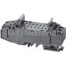
Blanking Piece in -F3 Frame
Y303-885-31
Part Number
Y303-885-31
Price
Request Quote
Manufacturer
E-T-A
Lead Time
Request Quote
Category
Circuit Protection » Circuit Breaker Accessories
Specifications
Manufacturer
E-T-A
Manufacturers Part #
Y303-885-31
Industry Aliases
Y 303 885 31, Y303 885 31
Sub-Category
Circuit Breaker Accessories
Factory Pack Quantity
1
Datasheet

Extracted Text
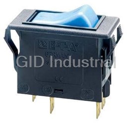
Thermal Circuit Breaker 3120-F... Description The 3120 circuit breaker/switch combination is an ON/OFF switch with integral overcurrent protection (S-type TO CBE to EN/IEC 60934). The trip element is a bimetal. Type 3120 is ideally suited for overload protection of motors, pumps, transformers and cables. The 3120 circuit breaker is also available as a switch-only version in accordance with the IEC/EN 61058 (see data sheet switch 3120-F-..Q1). Product characteristics: l rocker or push button actuation l single pole and double pole versions l reliable switching behaviour (positively trip-free) l convenient snap-in mounting 1 l international approvals Options and add-on modules: l illumination l water splash protection Technical data l auxiliary contacts l under voltage trip For details please see Technical information l remote trip l magnetic trip Rated voltage AC 240 V, DC 50 V l push-in terminals Current rating range 0.1...20 A l appliance inlet module (up to 30A upon request for single pole units) Typical life 1-pole Typical applications AC 240 V: 0.1...20 A 30,000 operations at 1 x I , inductive N DC 50 V: 0.1...4 A 30,000 operations at 1 x I , inductive Medical and laboratory equipment, apparatus and machine N 4.5...16 A 30,000 operations at 1 x I , resistive construction, professional tools, household and garden appliances, N DC 28 V: 0.1...20 A 30,000 operations at 1 x I , inductive N offices machines, audio equipment, machine tools Typical life 2-pole Current ratings and internal resistance values AC 240 V: 0.1...16 A 50,000 operations at 1 x I , inductive N 17...20 A 30,000 operations at 1 x I , inductive N DC 50 V: 0.1...16 A 50,000 operations at 1 x I , inductive N Current rating Internal Current rating Internal 17...20 A 50,000 operations at 1 x I , inductive N (A) resistance (A) resistance Ambient temperature -30 … 60 °C per pole (Ω) per pole (Ω) Insulation coordination 2.5 kV /2 reinforced insulation at 0.1 94 4 0.0435 (IEC 60664) operating area 0.2 24 4.5 0.0435 Dielectric strength 0.3 12 5 0.0325 Operating area test voltage AC 3,000 V pole to pole (2-pole) test voltage AC 1,500 V 0.4 5.30 6 0.0215 Insulation resistance > 100 MΩ (DC 500 V) 0.5 4.20 7 0.0165 Interrupting capacity I 0.1...2 A 10 x I cn N 0.6 2.90 8 0.0165 2.5...20 A 1-pole 150 A 2-pole 250 A 0.8 1.50 10 < 0.02 Interrupting capacity (UL 1077) 1 0.9 12 < 0.02 I U I N N nc 1.2 0.80 14 < 0.02 1-pole, 2- pole 0.1...20 A AC 250 V 5000 A, C, 1 1.5 0.45 15 < 0.02 1-pole, 2- pole 0.1...20 A DC 50 V 1000 A, C, 1 2 0.27 16 < 0.02 Degree of protection operating area IP40 2.5 0.0785 18 < 0.02 (IEC 60529) terminal area IP00 with water splash cover IP54 or IP66 3 0.0595 20 < 0.02 Vibration 8 g (57-500 Hz), ± 0.61 mm (10-57 Hz) 3.5 0.0565 test to IEC 60068-2-6, test Fc 10 frequency cycles/axis Shock 30 g (11 ms) Current consumption of illumination test to IEC 60068-2-27, test Ea Corrosion 96 hours at 5 % salt mist, Operating voltage Current consumption test to IEC 60068-2-11, test Ka Y R G Humidity 240 hrs in 95 % RH DC 12 V 5.2 mA 2 mA 1.4 mA test to IEC 60068-2-78, test Cab DC 24 V 4.5 mA 2.2 mA 1.6 mA Mass approx. 33 g (2-pole) DC 48 V 4.5 mA 2 mA 1.6 mA approx. 27 g (1-pole) AC 115 V 2.8 mA 1.1 mA 1 mA approx. 42 g (2-pole with PT terminals) AC 230 V 2.2 mA 0.9 mA 0.9 mA 1806 www.e-t-a.de 1 Thermal Circuit Breaker 3120-F... Order numbering code Order numbering code Type No. Type No. 3120 thermal rocker-actuated circuit breaker 3120 thermal circuit breaker with push button actuation Mounting method Mounting F flange mounting snap-in frame F flange mounting snap-in frame Size of frame Size 3 standard, to fit mounting cut-out 50.5 x 21.5 mm 2 special frame for fitting splash cover 5 standard, to fit mounting cut-out 44.5 x 22 mm 3 mounting cut-out 50.5 x 21.5 mm (panel thickness 7 special style, to fit mounting cut-out 44.5 x 22 mm 1-6.35 mm) Number of poles Number of poles 1 1-pole, thermally protected 1 1-pole, thermally protected 2 2-pole, thermally protected 2 2-pole, thermally protected 5 2-pole, 1-pole thermally protected 5 2-pole, 1-pole thermally protected 1 Mounting frame design (F3 & F5) Style 1 collar height 1 mm F frame with 2 push buttons 3 collar height 9 mm G frame with one push button (reset only) 4 collar height 2 mm with water Terminal configuration splash protection (IP54) PT push-in terminals Mounting frame design (F7) P7 blade terminals R black H7 as P7, terminals 11 and 21 with flat head T black with snap-on water splash cover screws M3.5 - standard for units with Terminal configuration undervoltage release module PT push-in terminals N7 as P7, with additional shunt terminals 12(i) P7 blade terminals and 22(i) H7 as P7, terminals 11 and 21 with flat head G7 as N7, terminals 11 and 21 with flat head screws M3.5 - standard for units with screws M3.5 undervoltage release module Characteristic curve N7 as P7, with additional shunt terminals 12(i) T1 thermal trip and 22(i) Actuators / colour / illumination G7 as N7, terminals 11 and 21 with flat head D01X 1 push button* black opaque screws M3.5 D02X 1 push button* white opaque Characteristic curve D04X 1 push button* red opaque T1 thermal trip D19XG 1 push button* green translucent Actuator style with LED illumination W rocker for frame size F3 & F5 SGRX 2 push buttons green/red opaque A rocker for frame size F7 without illumination Colour and illumination SGRXG 2 push buttons green/red translucent 01. rocker black opaque with LED illumination 02. rocker white opaque Illumination voltage range 04. rocker red opaque (= operating voltage) 14. R rocker red translucent with 1 DC 12 V LED illumination 2 DC 24 V 15. Y rocker orange translucent with 3 AC 115 V LED illumination 4 AC 230 V 19. G rocker green translucent with 5 DC 48 V LED illumination Current ratings Marking for rocker style W 0.1...20 A A 0 D 3120- F 3 2 F - P7 T1- S GRXG 4-10 A ordering example I ON Q: 0 and 1 F 0 OFF moulded in Q *reset only I AD FX X Marking for rocker style A Packaging unit: Q »I« and »O« moulded in 20, 25, 35, 50 or 60 pcs, depending on the version Illumination voltage range (= operating voltage) 1 DC 12 V 2 DC 24 V 3 AC 115 V 4 AC 230 V 5 DC 48 V 3120 -F 7 2 R - P7 T1 -A 14 QR 4 Current ratings 0.1...20 A 3120 -F 7 2 R - P7 T1 -A 14 QR 4 - 10 A ordering example 2 www.e-t-a.de 1806 Thermal Circuit Breaker 3120-F... Thermal Circuit Breaker 3120-F... Preferred types Time/current characteristics preferred ratings (A) preferred type F7 single or double pole load 2-pole protected 0.5 1 1.5 2 3 4 5 6 8 10 12 15 16 20 0.1…2 A 3120-F72R-P7T1- x x x x x x x x x x x x x x 10000 +60 °C A14QR4- +140 °F preferred type F3 +23 °C 0.5 1 2 3 4 5 6 8 10 12 15 16 20 +73.4 °F 1-pole protected -30 °C 3120-F311-P7T1- 1000 -22 °F x x x x x x x x W02D- preferred type F3 0.5 1 2 3 4 5 6 8 10 12 15 16 20 2-pole protected 1 100 3120-F321-P7T1- x x x x x x x x x x x x x W01D- preferred type F5 0.5 1 2 3 4 5 6 8 10 12 15 16 20 2-pole protected 10 3120-F521-P7T1- x x x x x x x x x x x x W01D- 1 Approvals Approval Standard Rated Current rating range authority voltage 0.1 12 46 8102040 AC 240 V 0.1 A…20 A VDE IEC/EN 60934 … times rated current DC 50 V 0.1...20A (2-pole) 2.5…20 A DC 50 V 0.1...4 A (1-pole) 10000 +60 °C DC 28 V 0.1 A…20 A +140 °F +23 °C AC 250 V 0,1 A…20 A UL UL 1077 +73.4 °F DC 50 V 0,1 A…20 A -30 °C AC 250 V 30 A (2 poles in par- 1000 -22 °F allel) AC 250 V 0,1 A…20 A CSA C22.2 No 235 DC 50 V 0,1 A…20 A AC 250 V 30 A (2 poles in parallel) 100 AC 240 V 0.1 A…20 A CQC GB 17701 DC 50 V 0.1 A…20 A 10 Schematic diagrams 2-pole, 2-pole, 1 thermally protected on both poles thermally protected on one pole only line line 11 21 11 21 0.1 12 46 8102040 12(i) 22(i) 12(i) 22(i) … times rated current 12(k) 22(k) 12(k) load load The time/current characteristic depends on the ambient temperature. In order to eliminate nuisance tripping, please multiply the current 1-pole, rating by a derating factor (see chapter Technical Information) thermally protected line 11 ambient -30 -20 -10 0 23 40 50 60 temperature [°C] 12(i) 22(i) Temperature factor 0.8 0.84 0.88 0.92 1 1.08 1.14 1.23 12(k) load 1806 www.e-t-a.de 3 Trip time in seconds Trip time in seconds Thermal Circuit Breaker 3120-F... Dimensions 12.65 12.65 5.5 3120-F2.F-… 3120-F2.F-PT... water splash cover (see accessories) retaining clip panel cover 35.4 74 hole for screw ±0.1 16.2 60 ø 4 mm e.g.: EJOT PT 16.1 14.1 screw K40 1 ø3.2 ø 3.2 PT-screw 12(i)12(k) 11 12(i) 12(k) 11 type K40 ø4 mm 10.7 3.5 3 21 15.5 21 42.5 41 blade terminal EN 60934 – 6.3 x 0.8 flat head screw M3.5x6 tightening torque max. 0.8 Nm 12.65 12.65 3120-F3.1-PT 5.5 3120-F3.1 25 OFF position 25 16 16 54 54 12(i)12(k) 11 12(i) 12(k) 11 3.5 3 10.7 21 15.5 42.5 21 41 blade terminal EN 60934 – 6.3 x 0.8 flat head screw M3.5x6 tightening torque max. 0.8 Nm 3120-F 3.3 3120-F 3.4 collar height 9 mm with water splash protection (IP54) 25 54 27 56 19.5 35 35 19.5 12(i) 12(k) 11 12(i)12(k) 11 10.7 3.5 3 10.7 3.5 3 21 21 15.5 15.5 41 41 blade terminal EN 60934 – 6.3 x 0.8 blade terminal EN 60934 – 6.3 x 0.8 flat head screw M3.5x6 flat head screw M3.5x6 tightening torque max. 0.8 Nm tightening torque max. 0.8 Nm 4 www.e-t-a.de 1806 15 10 35 7 35 9 4.5 33 33 33 10.2 10 10 10 14 3.8 10 9 3.5 33 49 10.2 48 9 10 10.7 10.7 Thermal Circuit Breaker 3120-F... Thermal Circuit Breaker 3120-F... Dimensions 3120-F3.F-…-S… 3120-F3.G-...-D... optional illumination in ON position optional illumination in ON position OFF position OFF position 25 54 54 25 16.2 16.2 14.2 14.2 1 12(i) 12(k) 11 12(i) 12(k) 11 10.7 10.7 3.5 3 3.5 3 21 21 15.5 15.5 41 41 blade terminal EN 60934 – 6.3 x 0.8 blade terminal EN 60934 – 6.3 x 0.8 flat head screw M3.5x6 flat head screw M3.5x6 tightening torque max. 0.8 Nm tightening torque max. 0.8 Nm 12.65 12.65 5.5 3120-F 5.1 3120-F5.1-PT 25 25 optional illumination 16 16 48 48 12(i) 12(k)11 12(i)12(k) 11 10.7 3.5 3 21 15.5 42.5 21 blade terminal EN 60934 – 6.3 x 0.8 41 flat head screw M3.5x6 tightening torque max. 0.8 Nm 3120-F5.3 3120-F5.4 48 25 48 25 19.5 19.5 35 35 12(i) 12(k) 11 12(i) 12(k)11 3.5 3 3.5 3 10.7 10.7 15.5 21 15.5 21 41 41 blade terminal EN 60934 – 6.3 x 0.8 blade terminal EN 60934 – 6.3 x 0.8 flat head screw M3.5x6 tightening torque max. 0.8 Nm flat head screw M3.5x6 tightening torque max. 0.8 Nm 1806 www.e-t-a.de 5 15 35 7 10 33 33 33 2 11 10 10 15 10 2 33 33 11 48 9 10 10.7 3120-F3… - 0.4 -.016 - 0.2 -.008 min. 2.5 min .098 max.R2 max .079 Thermal Circuit Breaker 3120-F... ±0.05 ±.002 +0.3 50.5 +.012 1.99 max. R0.3 Dimensions Cut-out dimensions max .012 t: metal min. 2 mm (.079 in.) 3120-F2… Style F7.R plastic min. 3 mm (.118 in.) ±0.2 25 48 60±0.15 ±.008 .984 1.89 +.006 2.36 15.5 44.2-0.2 +0.5 50.5 R2 .610 1.74-.008 +.020 1.99 .079 LINE 12(i)12(k) 11 1 Edges of working parts: ISO 13715 10.7 3.5 3 .421 .138 .118 Cut-out for mounting style -F3 Cut-out for mounting 21 15.5 with rocker and push button style -F5/-F7 .827 .610 41 - 0.4 - 0.4 with rocker -.016 1.61 -.016 blade terminals EN60934 - 6,3 x 0,8 - 0.2 - 0.2 min. 2 -.008 -.008 min. 2.5 min .079 flat head screw M3.5x6 min .098 max. R1.5 tightening torque max. 0.8 Nm max. R2 max .059 max .079 ±0.05 ±.002 ±0.05 ±.002 +0.2 44.5 +0.3 50.5 +.008 max. R0.3 1.75 +.012 1.99 max .012 3120-F7.R-PT max. R0.3 max .012 Edges of working parts: ISO 13715 12.65 12.65 5.5 25 0.49 0.49 0.22 .984 15.5 Cable cross sections PT terminals 48 .610 1.89 cable cross section with direct push-in wiring 2 rigid 1…4 mm (stripping length: 10 mm) 12(i)12(k) 11 2 flexible with wire end ferrule 0.5…2.5 mm (with or without plastic sleeve) cable cross section when opening 21 42.5 the push-in terminals .827 1.67 2 rigid 0.5…4 mm (stripping length: 10 mm) 2 flexible without wire end ferrule 0.5…2.5 mm Style F7.T 34 60 1.34 2.36 18.6 44.8 .732 1.76 LINE 12(i)12(k) 11 3.5 3 10.7 .118 .421 .138 21 15.5 .827 .610 41 1.61 blade terminals EN60934 - 6,3 x 0,8 flat head screw M3.5x6 tightening torque max. 0.8 Nm 6 www.e-t-a.de 1806 33 33 8.9 1.30 1.30 .350 48 9.4 1,89 0.37 10.7 10 3 10 11.5 0.42 .394 .118 .394 .453 +0.2 21.5 1-6.35 +.008 .846 .039-.250 +0.2 1-6.35 26 +.008 .039-.250 1.02 0.2 21.5+ t +.008 .846 +0.2 ø4.3 +.008 1-4 mm .169 .039-.157 in. +0.3 22 +.012 .866 Thermal Circuit Breaker 3120-F... Thermal Circuit Breaker 3120-F... Installation drawing Terminal types 3120-F521-G7 3120-F551-G7 3120 with blade terminals When installing the circuit breaker apply pressure on bezel only. operating area 1 8 710 7 7 mounting area 3120-F521-N7 3120-F551-N7 3120 with push-in terminals When installing the circuit breaker apply pressure on bezel only. operating area 8 710 7 7 mounting area 3120-F521-H7 3120-F551-H7 3120-F521-P7 3120-F551-P7 1806 www.e-t-a.de 7 10 25 15.5 30.5 R3.5 .138 Thermal Circuit Breaker 3120-F... Accessories Insulated cover Rear terminal shroud black (IP64) Y 303 068 01 Y 304 275 01 2.5 40.5 +0.5 1.59 1.75 20.5 .098 -0.25 +.020 .069 .807 -.010 20 .787 1 Terminal adapter Y 303 862 01 4 ø8 .157 .315 Water splash cover, transparent (IP66) for mounting style -F2.. X 221 619 01 48 1.89 blade terminal DIN 46244-C-Ms-S (QC 2x.110) Blanking piece in -F3 frame ø8 Y 303 885 31 .315 54 25 matt finish 2.13 .984 ø4.4 31 16.5 .650 .173 1.22 60 2.36 73 2.87 41 21 1.61 .827 Mounting of X221 619 01 All dimensions without tolerances are for reference only. E-T-A reserves the right change specifications at any time in the interest of improved design, performance and cost effective- ness, the right to make changes in these specifications without notice is reserved. Product markings may not be exactly as the ordering codes. Errors and omissions excepted. 8 www.e-t-a.de 1806 1 .039 13.5 .531 4 .157 0.9 .035 9 .354 3.7 .146 33 1.30 36 1.42 3.4 .134 10 50 .394 1.97 35 16.5 25 1.38 .984 .650 +5 70 +.197 2.76 Thermal Circuit Breaker 3120-F... Thermal Circuit Breaker 3120-F... Accessories Plug-in connector Y 31214001 Connecting cables can be pre-wired. Two retaining clips ensure a tight fit. 1 5,5 12 42 21,2 Benefits: • Reduced installation time and costs for final assembly • Quick replacement of devices Note: Delivery without receptacles. Dimensions of receptacles (width 6.3 mm) are in accordance with DIN 46340 part 3, shape A. Examples of suitable receptacles: Stocko RSB 7916 F6,3-1 / Klaucke type 2730 / Vogt type 3832d.67 / TE FASTON Terminals 250 Series / Delphi Packard 58 Series Plug-in connector mounted on circuit breaker: 21,2 42 1806 www.e-t-a.de 9 24 33 24 4,5 Thermal Circuit Breaker 3120-F... Description - Appliance inlet module X3120-A/-B The appliance inlet module X3120 with circuit breaker type 3120-F5/ -F7/-F8 combines up to four functions within a single component: A C14/C20 appliance inlet, a rocker-actuated or push button switch and resettable overcurrent protection and a filter. Screw-type mount- ing from the front or from the rear. Typical applications Electrical medical apparatus, laboratory equipment, professional audio equipment and office machines. 1 X3120-A X3120-B Approvals X3120-A – C14 inlet Authority Standard Voltage ratings Max. current Order numbering code ENEC AC 240 V 10 A IEC/EN Type No. 60320-1 X3120 Appliance inlet module for circuit breaker type 3120 UL/CSA AC 250 V 15 A UL 498 Module CQC CCC AC 250 V 10 A A appliance inlet C14 (with filter) B appliance inlet C20 (without filter) Mounting Approvals X3120-A – filter 04 screw-type mounting Design coresponding to UL 1283, CSA 22.2 No. 8 1986, Filter IEC/EN 60939 00 without filter 01 general performance IEC inlet filter 03 general performance IEC inlet filter, medical version X3120-B – C20 inlet 06 high performance IEC inlet filter, medical version Authority Standard Voltage ratings Max. current Filter current rating ENEC AC 240 V 16 A IEC/EN 00 without filter 60320-1 01 1 A UL/CSA AC 240 V 20 A 03 3 A UL 498 06 6 A 08 8 A 10 10 A Selection current rating of the filter 12 12 A 15 15 A Version Current rating Minimum current rating of the filter 01 not wired; mounting position 3120: circuit breaker OFF position to connector 0,1...1 A 1 A 11 wired; mounting position 3120: OFF position to connector 1,2...3 A 3 A Assembly status 3,5...6 A 6 A M module supplied with circuit breaker 3120 and filter (module A) fitted 7...8A 8 A 9...10 A 10 A X3120- B 04 00 00 01 M ordering example 12 A 12 A 14...15 A 15 A Circuit breaker type 3120 with thermal release protects the filter in case of overloads. For the protection of the filter in the event of higher overcurrents we recommend circuit breaker type 3120 with thermal-magnetic release (3120...M1...). Further technical information upon request. All dimensions without tolerances are for reference only. In the interest of improved design, performance and cost effectiveness the right to make changes in these specifications with- out notice is reserved. Product markings may not be exactly as the ordering codes. Errors and omissions excepted. 10 www.e-t-a.de 1806 Thermal Circuit Breaker 3120-F... Thermal Circuit Breaker 3120-F... Technical Data (type X3120-B, without filter) Technical Data (type X3120-A with filter) Rated voltage AC 240 V Rated voltage AC 250 V Current rating 16 A (IEC) Current rating (inlet) 10 A (IEC) (inlet) 20 A (UL/CSA) 15 A (UL/CSA) Ambient temperature -25°C ...+60°C Current rating (filter) 1 A, 3 A, 6 A, 8 A, 10 A, 12 A, 15 A Ambient temperature -25°C ...+60°C Number of poles L, N + earth Number of poles L, N + earth Protection class: I Protection class: I Mounting method: screw-type mounting (front or rear) Mounting method: screw-type mounting Connection: blade terminals DIN 46244 (front or rear) 6.3 mm x 0.8 mm 1 Connection: blade terminals DIN 46244 Housing material: thermoplastics, black UL94V-0 6.3 mm x 0.8 mm Housing material: thermoplastics, black UL94V-0 Appliance inlet: C20 according to IEC/EN 60320-1, UL498 Appliance inlet: C14 according to IEC/EN 60320-1, Mains switch: Circuit breaker 3120-F5/-F7/-F8 UL498 (3120-F8 with push button actuation: Mains switch: Circuit breaker 3120-F5/-F7/-F8 technical data upon request) (3120-F8 with push button actuation: technical data upon request) Dimensions (type X3120-B) Dimensions (type X3120-A) 40 11.8 5.5 .465 1.57 0.21 circuit breaker 3120 26 Ø 3.3 Ø 3.3 1.0 Ø .130 49.3 37 47 Ø .130 36.2 1.457 1.85 1.43 1.94 Cut-out dimensions (type X3120-B) Cut-out dimensions (type X3120-A) +.0 R3.0 (4x) -1.0 +.3 72.0 -.0 +.00 .12 (4x) -.03 +.01 2.83 79.5 ±0.3 -.00 80.0 ± .1 90 ±0.1 3.15±.00 1806 www.e-t-a.de 11 M3/ Ø3.3 90 3.54 100 3.9 32.5 ±0.3 Ø 3.6 (2x) Ø .14 (2x) 80 3.15 91.5 3.60 +.3 29.0 -.0 +.01 1.14 -.00 Thermal Circuit Breaker 3120-F... Electrical schematics X3120-A X3120-A0401 General performance filter Cx 2xL 2xCy N' 11 N 12 (K) PE PE 3120 22 (K) P Line P' 21 Load X3120-A0403 und X3120-A0406 1 Medical version Cx RN 2xL ' 11 12 (K) N PE 3120 PE 22 (K) P Line P' 21 Load X3120-A0401 and X3120-A0403 - General performance filter Typical filter attenuation: Per CISPR 17 A = 50 Ω / 50 Ω sym; B = 50 Ω / 50 Ω asym; C = 0.1 Ω / 100 Ω sym; D = 100 Ω / 0.1 Ω sym 1 and 3 A types 6 to 10 A types 12 and 15 A types X3120-A0406 - High performance filter Typical filter attenuation: Per CISPR 17 A = 50 Ω / 50 Ω sym; B = 50 Ω / 50 Ω asym; C = 0.1 Ω / 100 Ω sym; D = 100 Ω / 0.1 Ω sym 1 and 3 A types 6 to 10 A types 12 and 15 A types 12 www.e-t-a.de 1806 Thermal Circuit Breaker 3120-F... Thermal Circuit Breaker 3120-F... Filter selection table Filter Rated current Leakage current Inductance L Capacitance Cx Capacitance Cy Resistance R 50°C (25°C) 250VAC/50 Hz mH µF nF kΩ A µA X3120-A040101..M 373 12 0.1 2.2 1 (1.2) X3120-A040103..M 373 2.5 0.1 2.2 3 (3.5) X3120-A040106..M 6 (7.2) 373 0.78 0.1 2.2 X3120-A040108..M 8 (10.6) 373 0.5 0.1 2.2 X3120-A040110..M 10 (11.6) 373 0.225 0.1 2.2 1 X3120-A040112..M 12 (12) 373 0.11 0.1 2.2 X3120-A040115..M 15 (15) 373 0.075 0.1 2.2 X3120-A040301..M 1 (1.2) 2 12 0.1 1000 X3120-A040303..M 3 (3.5) 2 2.5 0.1 1000 X3120-A040306..M 6 (7.2) 2 0.78 0.1 1000 X3120-A040308..M 8 (10.6) 2 0.5 0.1 1000 X3120-A040310..M 10 (11.6) 2 0.225 0.1 1000 X3120-A040312..M 12 (12) 2 0.11 0.1 1000 X3120-A040315..M 15 (15) 2 0.075 0.1 1000 X3120-A040601..M 1 (1.2) 2 59.53 0.1 1000 X3120-A040603..M 3 (3.5) 2 13.45 0.1 1000 X3120-A040606..M 6 (7.2) 2 4.1 0.1 1000 X3120-A040608..M 8 (10.6) 2 2.3 0.1 1000 X3120-A040610..M 10 (11.6) 2 1.02 0.1 1000 X3120-A040612..M 12 (12) 2 0.58 0.1 1000 X3120-A040615..M 15 (15) 2 0.4 0.1 1000 1806 www.e-t-a.de 13 U< U< U< 15° Thermal Circuit Breaker 3120-F... Description undervoltage release module X3120-U Dimensions Add-on module for circuit breaker type 3120. The undervoltage release flat head screw M3.5x6 +0.1 41 - 0.2 module trips the 3120 circuit breaker/switch combination in the event for mains connection tightening torque max. 0.8 Nm +.004 of a voltage drop or power failure. When the voltage is restored, the 1.61 - .008 3120 must be reset to reconnect the load, thereby avoiding the safety hazards associated with automatic re-start of machinery. Note: Basic unit 3120-...-H7 or -G7 requires screw terminals. Not possible in combination with PT terminals. Typical applications 1 All machines and devices where automatic re-start after restoration 6.6 of power could be dangerous, e.g. drilling machines, electric saws, .260 21 blade terminal sausage slicers etc. 21 .827 DIN 46244-A2.8-0.8 .827 (QC .110) 22 1 terminal .866 X3120-U01… 23.5 Order numbering code .925 Without separate terminal(s): X3120-U00… Type No. X3120 module for type 3120 Schematic diagrams Module U undervoltage release module Design 00 standard (without separate connections) X3120-U00… X3120-U01… X3120-U02… 01 1 blade terminals 2.8x0.8 02 2 blade terminals 2.8x0.8 line line line line line 11 21 11 A2 21 11 A1 A2 21 Rated voltage 00 AC 230/240 V 50/60 Hz 01 AC 120 V 50/60 Hz Assembly status M module mounted to circuit breaker 3120 12(i) 22(i) 12(i) 22(i) 12(i) 22(i) X3120- U 00 00 M ordering example 12(k) 22(k) 12(k) 22(k) 12(k) 22(k) load load load Technical data Voltage ratings AC 100 V; 120 V; 230/240 V (50/60 Hz); DC 24 V Voltage tolerances + 10 % / - 15 % Typical life 20,000 cycles Current consumption approx. 2.5 mA Release values 0.2 x U < U < 0.7 x U N N (at a rated voltage of AC 100 V the device can trip at 70 V and must trip at 20 V) Release delay < 20 ms Latch-in values ≥ 85 % U N Ambient temperature -30 … 60 °C Vibration 8 g (57-500 Hz), ± 0.61 mm (10-57 Hz) test to IEC 60068-2-6, test Fc 10 frequency cycles/axis Shock 30 g (11 ms) test to IEC 60068-2-27, test Ea Corrosion 48 hours at 5 % salt mist, test to IEC 60068-2-11, test Ka Humidity 240 hrs in 95 % RH test to IEC 60068-2-78, test Cab Mass approx. 53 g (including base unit) All dimensions without tolerances are for reference only. E-T-A reserves the right change specifications at any time in the interest of improved design, performance and cost effective- ness, the right to make changes in these specifications without notice is reserved. Product markings may not be exactly as the ordering codes. Errors and omissions excepted. 14 www.e-t-a.de 1806 33.5 1.32 7.6 .299 Thermal Circuit Breaker 3120-F... Thermal Circuit Breaker 3120-F... Description auxiliary contact module X3120-S Dimensions Add-on module for circuit breaker type 3120-F. The auxiliary contact module has a change-over contact as signal contact and is operated with actuation of the CBE. Not possible in combination with PT terminals. Typical applications 10 21 Status monitoring of CBE and/or the connected loads. .394 .827 14 .551 blade terminals DIN 46244-A2.8-0.5-Ms (QC .110) 1 Order numbering code plated Type No. X3120 module for types 3120 and 3140 7.5 7.5 .295 .295 Module 2 S auxiliary contact module 19.8 .079 .780 Contact configuration 0 change-over contact Terminal design Schematic diagram 1 blade terminals 2.8 x 0.5 (QC .110), silver-plated Contact rating AC voltage DC voltage line rated voltage rated rated rated 11 21 34 32 current voltage current 12 V 0.1...4 A module mounted 24 V 0.1...4 A A 10 V - 250 V 0.1...4 A 60 V 0.1...1 A 12(i) 22(i) 31 110 V 0.1...0.5 A 220 V 0.1...0.25 A 12(k) 22(k) 5 ...100 5 V - 250 V 5...100 mA load B 5 V - 250 V mA Assembly status M module mounted to circuit breaker 3120 Technical data X3120- S 0 1 A M ordering example Rated voltage AC 250 V, DC 220 V * without approval mark Current ratings 0.1...4 A / 5...100 mA Typical life 50,000 cycles Ambient temperature -30…60 °C Dielectric strength between main and test voltage AC 3,000 V auxiliary circuit Insulation resistance > 100 MOhm (DC 500 V) Vibration 6 g (57-500 Hz), ± 0.46 mm (10-57 Hz) test to IEC 60068-2-6, test Fc 10 frequency cycles/axis Shock 15 g (11 ms) test to IEC 60068-2-27, test Ea Corrosion 96 hours at 5 % salt mist, test to IEC 60068-2-11, test Ka Humidity 240 hrs in 95 % RH test to IEC 60068-2-78, test Cab Mass approx. 38 g (including base unit) All dimensions without tolerances are for reference only. E-T-A reserves the right change specifications at any time in the interest of improved design, performance and cost effective- ness, the right to make changes in these specifications without notice is reserved. Product markings may not be exactly as the ordering codes. Errors and omissions excepted. 1806 www.e-t-a.de 15 8.5 .335 25.5 1.00 Thermal Circuit Breaker 3120-F... Description remote trip module X3120-M Dimensions A module which adds remote trip capability to all versions of type 3120-F. A voltage applied across the coil, by means of an external sensor for example, will cause disconnection of the main switch/ circuit breaker mechanism. Not possible in combination with PT terminals. Typical applications Electrical remote trip of safety systems. 1 Order numbering code 10.7 18 .421 blade terminals .709 Type No. DIN 46244-C-Ms-S 21 14 (QC 2x.110) .827 .551 X3120 module for type 3120 Module M magnetic relay trip module Style 2 magnetic remote trip coil Schematic diagram Terminal design P7 blade terminals DIN 46244-A6.3-0.8 Assembly status line M module mounted to circuit breaker 3120 11 21 Rated voltage AC 120, 230 V DC 12, 24 V 12(i) 22(i) X3120- M 2 P7 M -12 V ordering example 12(k) 22(k) load 12(n) remote trip Standard voltage ratings and typical internal FA module 12 mounted resistance values voltage rating internal voltage rating internal internal internal Technical data resistance (Ω) resistance (Ω) DC 12 V 0.78 AC 120 V 71.0 Voltage ratings AC 120...230 V; DC 12...24 V DC 24 V 3.3 AC 230 V 312 Power consumption approx. 200 Watt Pulse operation 20 ms < t < 100 ms / t > 10 sec ON OFF Trip time < 20 ms Typical life 50,000 operations at U N Ambient temperature -30…60 °C Dielectric strength between main test voltage AC 3,000 V and trip current circuit Insulation resistance > 100 MOhm (DC 500 V) Vibration 8 g (57-500 Hz), ± 0.61 mm (10-57 Hz) test to IEC 60068-2-6, test Fc 10 frequency cycles/axis Shock 30 g (11 ms) test to IEC 60068-2-27, test Ea Corrosion 96 hours at 5 % salt mist, test to IEC 60068-2-11, test Ka Humidity 240 hrs in 95 % RH test to IEC 60068-2-78, test Cab Mass approx. 53 g (including base unit) All dimensions without tolerances are for reference only. E-T-A reserves the right change specifications at any time in the interest of improved design, performance and cost effective- ness, the right to make changes in these specifications without notice is reserved. Product markings may not be exactly as the ordering codes. Errors and omissions excepted. 16 www.e-t-a.de 1806 30 9 1.18 .354
Frequently asked questions
How does Electronics Finder differ from its competitors?

Is there a warranty for the Y303-885-31?
Which carrier will Electronics Finder use to ship my parts?
Can I buy parts from Electronics Finder if I am outside the USA?
Which payment methods does Electronics Finder accept?
Why buy from GID?

Quality
We are industry veterans who take pride in our work

Protection
Avoid the dangers of risky trading in the gray market

Access
Our network of suppliers is ready and at your disposal

Savings
Maintain legacy systems to prevent costly downtime

Speed
Time is of the essence, and we are respectful of yours
Related Products
Module 17plus, Centre Piece, Two-way 17PLUS-Q02-00
Request a Quote

The quote request has been received
Close

Facing challenges or have inquiries? Feel free to contact us!
Call Us +1-469-283-2440
What they say about us
FANTASTIC RESOURCE
One of our top priorities is maintaining our business with precision, and we are constantly looking for affiliates that can help us achieve our goal. With the aid of GID Industrial, our obsolete product management has never been more efficient. They have been a great resource to our company, and have quickly become a go-to supplier on our list!
Bucher Emhart Glass
EXCELLENT SERVICE
With our strict fundamentals and high expectations, we were surprised when we came across GID Industrial and their competitive pricing. When we approached them with our issue, they were incredibly confident in being able to provide us with a seamless solution at the best price for us. GID Industrial quickly understood our needs and provided us with excellent service, as well as fully tested product to ensure what we received would be the right fit for our company.
Fuji
HARD TO FIND A BETTER PROVIDER
Our company provides services to aid in the manufacture of technological products, such as semiconductors and flat panel displays, and often searching for distributors of obsolete product we require can waste time and money. Finding GID Industrial proved to be a great asset to our company, with cost effective solutions and superior knowledge on all of their materials, it’d be hard to find a better provider of obsolete or hard to find products.
Applied Materials
CONSISTENTLY DELIVERS QUALITY SOLUTIONS
Over the years, the equipment used in our company becomes discontinued, but they’re still of great use to us and our customers. Once these products are no longer available through the manufacturer, finding a reliable, quick supplier is a necessity, and luckily for us, GID Industrial has provided the most trustworthy, quality solutions to our obsolete component needs.
Nidec Vamco
TERRIFIC RESOURCE
This company has been a terrific help to us (I work for Trican Well Service) in sourcing the Micron Ram Memory we needed for our Siemens computers. Great service! And great pricing! I know when the product is shipping and when it will arrive, all the way through the ordering process.
Trican Well Service
GO TO SOURCE
When I can't find an obsolete part, I first call GID and they'll come up with my parts every time. Great customer service and follow up as well. Scott emails me from time to time to touch base and see if we're having trouble finding something.....which is often with our 25 yr old equipment.
ConAgra Foods