

 Manufacturers
EBM-PAPST INC. 3660
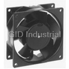
Description
AC Fan Axial Sleeve Bearing 115V/230V 53CFM 41dB 92.5 X 92.5 X 38mm
3660
Part Number
3660
Price
Request Quote
Manufacturer
EBM-PAPST INC.
Lead Time
Request Quote
Category
Thermal Management » Blowers and Fans
Specifications
Manufacturer
ebm-papst Inc.
Manufacturers Part #
3660
Lead Time
18 Week Lead Time
Industry Aliases
3660
Sub-Category
Thermal Management Blowers and Fans
Factory Pack Quantity
1
Datasheet

Extracted Text
Automotive BL-DC Fans for Commercial Vehicles Edition 2016-08 Automotive_2016_16_08_2016_AE_Final_.indd 1 16.08.2016 08:47:59 Automotive BL-DC Fans for Commercial Vehicles Our automotive products BL-DC axial fans and BL-DC dual Benefits and characteristics at a glance centrifugal fans with housing are ground breakers in the field - over 40.000 operating hours of commercial vehicle air conditioning. - variable speed control - high efficiency They not only meet the increased demands for comfort, e.g. in - low sound emission thanks to aerodynamically optimized impellers buses but also work wear-free for over 40.000 operating hours - increased reliability due to the electronics’ high integration density as they are brushless. - can be retrofitted into existing systems No additional maintenance, no additional servicing. - compliance with the most stringent EMC requirements - configurable control curve This corresponds to the usual reliability expected from ebm-papst. - optimized voltage independence - extended temperature range Data is subject to change without notice at ebm-papst discretion. - long-life ball bearings EC dual centrifugal blower: for top performance in minimal installation space; easy to regulate and extremely quiet. 2 Automotive_2016_16_08_2016_AE_Final_.indd 2 16.08.2016 08:48:00 2016-08 Contents Our automotive products ..... 2 EC centrifugal fan, forward curved 57 About ebm-papst 4 EC centrifugal fans - RadiCal, backward curved 61 Ideas for changing technology in commercial vehicles 6 Technology: EC dual centrifugal fan with housing "Premium" 8 - Cables 70 EC dual centrifugal fan with housing "Basic" 21 - Accessories 72 EC axial fans "Premium & Power" 27 - Conn. diagrams 74 EC axial fans "Basic" 51 - Technical parameters & scope 86 ebm-papst agents 90 3 Automotive_2016_16_08_2016_AE_Final_.indd 3 16.08.2016 08:48:02 2016-08 EC centrifugal fans - RadiCal EC centrifugal fans EC axial fans EC axial fans EC dual centrifugal fans EC dual centrifugal fans Agents Technology Information backward-curved forward-curved "Basic" "Premium & Power" with housing "Basic" with housing "Premium" About ebm-papst As a leader in technologies for ventilation and drive engineering, ebm-papst is in demand as an engineering partner in many sectors. With over 15,000 different products, we provide the right solution for just about any challenge. Our fans and drives are reliable, quiet and energy-efficient. Six reasons that make us the ideal partner: Proximity to our customers. ebm-papst owns 57 sales offices worldwide, of which 47 are sub sidiaries Our systems expertise. with an extensive network of sales representatives and distributors. You You want the best solution for every project. The inter relationships will always have a local contact, someone who speaks your language and between ventilation and drive engineering must thus be considered knows your market. as a whole. And that’s what we do – with motor technology that sets standards, sophisticated electronics and aerodynamic designs – Our standard of quality. all from a single source and perfectly matched. These system solutions Of course you can rely on the highest standards of quality with our pro- release unique synergies worldwide. And in particular – they relieve you ducts. Our quality management is uncompromising, at every step in every of a lot of work, so that you can concentrate on your core competency. process. This is underscored by our certification according to international standards including DIN EN ISO 9001, ISO/TS 16949-2 and DIN EN ISO The ebm-papst spirit of invention. 14001. In addition to our wide range of products, we are always able to develop customized solutions for you. A diversified team of 600 engineers and Our sustainable approach. technicians works at our three locations in Germany: Mulfingen, Landshut Assuming responsibility for the environment, for our employees and for and St. Georgen. Contact us to discuss your next project. society is an integral part of our corporate philosophy. We develop products with an eye to maximum environmental compatibility, in particu- Our lead in technology. lar resource-preserving production methods. We promote environmental As pioneer and trail-blazer for developing highly efficient EC tech nology, awareness among our young staff and are actively involved in sporting, we are way ahead of other motor manufacturers. Almost our entire product cultural activities and education. That’s what makes us a leading company range is also available with GreenTech EC technology. The list of benefits is – and an ideal partner for you. long: higher efficiency, main tenance-free, longer service life, sound reduc- tion, intelligent control characteristics and incomparable energy efficiency with savings of up to 80 % compared to conventional AC technology. Let our technology be your competitive advantage as you lead in your industry. 4 Automotive_2016_16_08_2016_AE_Final_.indd 4 16.08.2016 08:48:02 2016-08 The story of our success to market and technology pioneer. 1963 Founding of Elektrobau Mulfingen GmbH & Co. KG by Gerhard Sturm and Heinz Ziehl. 1965 First tubeaxial fan developed in EC/DC technology. 1966 ebm-papst’s success takes off with the new 68 motor. 1972 The first ebm-papst foreign subsidiary is established in Sweden. 1988 Gerhard Sturm is awarded the Federal Cross of Merit. 1990 The sixty-millionth external-rotor fan is produced. 1992 Acquisition of PAPST Motoren GmbH in St. Georgen. 1997 Buyout of the Landshut (mvl) plant. 1998 Development of first fans with integrated electronics. 2003 Change of name to ebm-papst. ® 2008 The HyBlade range of fans sets new efficiency standards. 2010 GreenTech – our sign for energy efficiency and resource preservation. 2011 RadiCal defines a new standard for EC centrifugal fans. 2013 ebm-papst takes over the gearbox specialist Zeitlauf and wins the German Sustainability Award. 2014 Team partnership with Mercedes AMG PETRONAS Formula 1 team. 2015 RadiPac pushes the limits of efficiency. 5 Automotive_2016_16_08_2016_AE_Final_.indd 5 16.08.2016 08:48:05 2016-08 EC centrifugal fans - RadiCal EC centrifugal fans EC axial fans EC axial fans EC dual centrifugal fans EC dual centrifugal fans Agents Technology Information backward-curved forward-curved "Basic" "Premium & Power" with housing "Basic" with housing "Premium" Ideas for changing technology in commercial vehicles Climate comfort in a commercial vehicle is anything but a question of Fans and blowers: convenience. Both the transportation of people in buses and coaches, for commercial vehicle air conditioning and cooling of individual compo- as well truck journeys which are as stress and fatigue-free as possible, nents. place high demands on vehicle technology; predominantly air conditioning, ventilation, and heating. For many years, major bus manufacturers have been installing air condi- tioners with brushless and wear-free centrifugal blowers and axial fans from ebm-papst. In the mean time, these products are also now widely used in the air conditioning and ventilation systems for the cabs in trucks, tractors and construction machinery, as well as in transport refrigeration systems. A number of air conditioning manufacturers rely on our experience and outstanding expertise in the core competencies of engine development, aerodynamics, and electronics. Counteracting high demands with new technologies: In modern commercial vehicles, EC technology has now become standard. Our new EC axial fans and EC dual centrifugal fans with second generation housing set a precedent in global commercial vehicle air However, ebm-papst has even more to offer: conditioning. Our EC fans have even been able to demonstrate their clear If you are unable to fi nd a solution amongst our products, speak to us. superiority in hot countries and tropical regions, where they have also As a competent consultant and practical implementer, we will certainly proven their worth. be able to fi nd you a solution thanks to our in-depth knowledge from many applications. But it is not just in the fi eld of air conditioning products where customers are relying on ebm-papst products: EC fans are increasingly being used for cooling heat exchangers in the engine compartment of vehicles. 6 Automotive_2016_16_08_2016_AE_Final_.indd 6 16.08.2016 08:48:06 2016-08 In comparison: In brush motors from various manufacturers, the commutator assumes the role of current distribution to the coils. The commutator consists of copper fins embedded in an insulating compound. Mechani- cal springs push the integrated carbon brushes to the commutator. These two rubbing mechanical components are the weak spot of conventional DC motors. After around 5,000 operating hours, the carbon brushes are run down and the commutator is worn. As a result, the entire blower must be replaced. In addition, it is only possible to regulate speed via external electronics. The brushless DC motors from ebm-papst are completely different. Here, an electronic controller directly integrated in the motor has the task of distributing current. No brushes means no wearing parts. This increases the service life of these motors to more than 40,000 hours. The user not This also requires special efforts in terms of the selection of materials and only saves money in terms of replacement parts and repair costs, he also testing of products. With the help of real-world extreme tests that we have avoids unproductive downtimes and a possible loss of image. defined in collaboration with leading OEMs (e.g., salt spray, vibration and temperature cycling tests), we are able to ensure the performance of the fans. Apart from the considerably longer service life, our intelligent EC fans provide advanced control and regulation possibilities. The functionality of the fans can be checked via a diagnostic output at any time. Furthermore, these display excellent electromagnetic compatibility traits and operate extremely quietly. EC motors are energy efficient, because the integrated electronics with variable speed control only draw the energy actually required from the on-board network. In the commercial vehicle sector, it is also crucial that fans withstand constantly changing environmental influences. Standard products would only provide unsatisfactory results here. For this reason, automotive products from ebm-papst are also reliably protected against load dumping, reverse polarity, shock and vibration, as well as damage from moisture and dirt penetration across a wide temperature range. 7 Automotive_2016_16_08_2016_AE_Final_.indd 7 16.08.2016 08:48:08 2016-08 EC centrifugal fans - RadiCal EC centrifugal fans EC axial fans EC axial fans EC dual centrifugal fans EC dual centrifugal fans Agents Technology Information backward-curved forward-curved "Basic" "Premium & Power" with housing "Basic" with housing "Premium" 8 Automotive_2016_16_08_2016_AE_Final_.indd 8 16.08.2016 08:48:09 2016-08 EC dual centrifugal fans with housing with brushless DC motor "Premium" 9 Automotive_2016_16_08_2016_AE_Final_.indd 9 16.08.2016 08:48:09 2016-08 EC centrifugal fans - RadiCal EC centrifugal fans EC axial fans EC axial fans EC dual centrifugal fans EC dual centrifugal fans Agents Technology Information backward-curved forward-curved "Basic" "Premium & Power" with housing "Basic" with housing "Premium" EC dual centrifugal fan with housing, for automotive applications, Ø 097 – Material: Housing: PP plastic, black (according to UL 94 HB) Blades: PA plastic (according to UL 94 HB) – Degree of protection: IP 24 KM – Insulation class: "B" according to EN 60335-1 – Installation position: Any – Mode: Continuous operation (S1) – Mounting: Maintenance-free ball bearings on both sides – Motor protection: Thermal overload protection, reverse polarity and locked-rotor protection, load dump protection, undervoltage detection – EMC regulations: VDE 0879-2 – Approvals: EAC; E1 in preparation Nominal data 3 Type Motor VDC VDC m /h rpm W A Pa dB(A) °C kg (1) (2) A M3G 084-BF P. 79 / D) K3G 097-AF22 -02 26 16-32 1150 3500 325 12,5 0 81 -40..+85 2,0 Subject to change (1) 24-volt version (2) above +70 °C with power derating Curves: n P I L A A ed W rpm W A dB(A) 800 A 1 3500 325 12,50 81 A 2 4025 293 11,25 79 A 3 4495 272 10,45 78 4 A 4 4930 250 9,59 80 600 3 400 2 200 1 0 100 200 300 400 500 600 cfm q 200 400 600 800 1000 m³/h v Air performance measured according to: ISO 5801, installation category A, in ebm-papst scroll housing without contact protection. Intake-side sound level: Lw according to ISO 13347, Lp measured at 1 m distance from fan axis. The values given are only ap- A A plicable under the specifi ed measuring conditions and may differ depending on the installation conditions. In the event of deviation from the standard confi guration, the parameters must be checked in installed condition. See Page 86 ff for detailed information. 10 Automotive_2016_16_08_2016_AE_Final_.indd 10 16.08.2016 08:48:10 2016-08 P Pa fs 0.5 1 1.5 2 2.5 3 in wg Curve Nominal voltage Nominal voltage range Air fl ow Speed Input power Input current Min. back pressure Sound power level Perm. ambient temp. Weight Techn. features and connection diagram P. 79 / D) 351 139.5 335 60 100 11 75.5 104 2.5 Ø 4.5 217.5 5 6 3 4 Connector detail 1 = UN 2 1 2 = GND 3 = PWM/LIN 4 = INVLIN 5 = ABSENK 6 = diagnostic output Tyco Junior Power Timer 929505-2, 6-pole, coded. Mating connector Tyco 929504-2 (not included in scope of delivery). Cable (460 mm) with mating connector, part no. 02001-4-1021 (not included in scope of delivery). Cable Connection 11 P. 70 diagram P. 79 Automotive_2016_16_08_2016_AE_Final_.indd 11 16.08.2016 08:48:11 101 90 64.5 45 18 10 10 60 136 170.5 2016-08 EC centrifugal fans - RadiCal EC centrifugal fans EC axial fans EC axial fans EC dual centrifugal fans EC dual centrifugal fans Agents Technology Information backward-curved forward-curved "Basic" "Premium & Power" with housing "Basic" with housing "Premium" EC dual centrifugal fan with housing, for automotive applications, Ø 097 – Material: Housing: PP plastic, black (according to UL 94 HB) Blades: PA plastic (according to UL 94 HB) – Degree of protection: Motor: IP 24 KM, electronics: IP 66 / 69 K – Insulation class: "B" according to EN 60335-1 – Installation position: Any – Mode: Continuous operation (S1) – Mounting: Maintenance-free ball bearings on both sides – Motor protection: Thermal overload protection, reverse polarity and locked-rotor protection, load dump protection, undervoltage detection – EMC regulations: VDE 0879-2 – Qualifi ed in accordance with: DIN ISO 16750 – Approvals: EAC; E1 in preparation Nominal data 3 Type Motor VDC VDC m /h rpm W A Pa dB(A) °C kg (1) (2) A M3G 084-BF P. 79 / D) K3G 097-AF22 -07 26 16-32 1150 3500 325 12,5 0 81 -40..+85 2,0 Subject to change (1) 24-volt version (2) above +70 °C with power derating This Typee is also available with a sealed plug. Curves: n P I L A A ed W rpm W A dB(A) 800 A 1 3500 325 12,50 81 A 2 4025 293 11,25 79 A 3 4495 272 10,45 78 4 A 4 4930 250 9,59 80 600 3 400 2 200 1 0 100 200 300 400 500 600 cfm q 200 400 600 800 1000 m³/h v Air performance measured according to: ISO 5801, installation category A, in ebm-papst scroll housing without contact protection. Intake-side sound level: Lw according to ISO 13347, Lp measured at 1 m distance from fan axis. The values given are only ap- A A plicable under the specifi ed measuring conditions and may differ depending on the installation conditions. In the event of deviation from the standard confi guration, the parameters must be checked in installed condition. See Page 86 ff for detailed information. 12 Automotive_2016_16_08_2016_AE_Final_.indd 12 16.08.2016 08:48:12 2016-08 P Pa fs 0.5 1 1.5 2 2.5 3 in wg Curve Nominal voltage Nominal voltage range Air fl ow Speed Input power Input current Min. back pressure Sound power level Perm. ambient temp. Weight Techn. features and connection diagram P. 79 / D) 139.5 X 60 351 11 335 100 75.5 104 217.5 Ø 4.5 6 4 2 Cable with plug (Plug is not sealed by the customer) 1 = +UB black X 2 = GND brown 3 = PWM/LIN yellow 5 3 1 4 = INVLIN orange 5 = ABSENK blue 6 = diagnostic output white Tyco Junior Power Timer 929505-2, 6-pole, coded. Mating connector Tyco 929504-2 (not included in scope of delivery). Cable Connection 13 P. 70 diagram P. 79 Automotive_2016_16_08_2016_AE_Final_.indd 13 16.08.2016 08:48:12 101 90 64.5 45 18 10 10 60 136 +20 79.5 415 99 170.5 2016-08 EC centrifugal fans - RadiCal EC centrifugal fans EC axial fans EC axial fans EC dual centrifugal fans EC dual centrifugal fans Agents Technology Information backward-curved forward-curved "Basic" "Premium & Power" with housing "Basic" with housing "Premium" EC dual centrifugal fan with housing, for automotive applications, Ø 097 – Material: Housing: PP plastic, black (according to UL 94 HB) Blades: PA plastic (according to UL 94 HB) – Degree of protection: IP 24 KM – Insulation class: "B" according to EN 60335-1 – Installation position: Any – Mode: Continuous operation (S1) – Mounting: Maintenance-free ball bearings on both sides – Motor protection: Thermal overload protection, reverse polarity and locked-rotor protection, load dump protection, undervoltage detection – EMC regulations: VDE 0879-2 – Approvals: EAC; E1 in preparation Nominal data 3 Type Motor VDC VDC m /h rpm W A Pa dB(A) °C kg (1) (2) A M3G 084-BF P. 79 / D) K3G 097-BF22 -02 26 16-32 1040 3700 300 11,7 0 80 -40..+85 2,0 Subject to change (1) 24-volt version (2) above +70 °C with power derating Curves: n P I L A A ed W rpm W A dB(A) 800 A 1 3700 300 11,70 80 A 2 4060 284 10,91 78 A 3 4580 263 10,10 78 4 A 4 4980 217 8,35 80 600 3 400 2 200 1 0 100 200 300 400 500 cfm q 200 400 600 800 m³/h v Air performance measured according to: ISO 5801, installation category A, in ebm-papst scroll housing without contact protection. Intake-side sound level: Lw according to ISO 13347, Lp measured at 1 m distance from fan axis. The values given are only ap- A A plicable under the specifi ed measuring conditions and may differ depending on the installation conditions. In the event of deviation from the standard confi guration, the parameters must be checked in installed condition. See Page 86 ff for detailed information. 14 Automotive_2016_16_08_2016_AE_Final_.indd 14 16.08.2016 08:48:13 2016-08 P Pa fs 0.5 1 1.5 2 2.5 3 in wg Curve Nominal voltage Nominal voltage range Air fl ow Speed Input power Input current Min. back pressure Sound power level Perm. ambient temp. Weight Techn. features and connection diagram P. 79 / D) 335 325 196 144.5 67 65 50 113.5 3 14.65 33.8 217.5 5 6 3 Connector detail 4 1 = UN 2 = GND 2 1 3 = PWM/LIN 4 = INVLIN 5 = ABSENK 6 = diagnostic output Tyco Junior Power Timer 929505-2, 6-pole, coded. Mating connector Tyco 929504-2 (not included in scope of delivery). Cable (460 mm) with mating connector, part no. 02001-4-1021 (not included in scope of delivery). Cable Connection 15 P. 70 diagram P. 79 Automotive_2016_16_08_2016_AE_Final_.indd 15 16.08.2016 08:48:14 70 50 4.8 8.5 55 129 92 163.5 2016-08 EC centrifugal fans - RadiCal EC centrifugal fans EC axial fans EC axial fans EC dual centrifugal fans EC dual centrifugal fans Agents Technology Information backward-curved forward-curved "Basic" "Premium & Power" with housing "Basic" with housing "Premium" EC dual centrifugal fan with housing, for automotive applications, Ø 097 – Material: Housing: PA plastic, black (according to UL 94 V0) Blades: PA plastic, black (according to UL 94 V0) – Degree of protection: Motor: IP 24 KM, electronics: IP 66 / 69 K – Insulation class: "B" – Installation position: Any – Mode: Continuous operation (S1) – Mounting: Maintenance-free ball bearings on both sides – Motor protection: Thermal overload protection, reverse polarity and locked-rotor protection, load dump protection, undervoltage detection – EMC regulations: VDE 0879-2 – Approvals: EAC; E1 in preparation Nominal data 3 Type Motor VDC VDC m /h rpm W A Pa dB(A) °C kg (1) A M3G 084-BF P. 83 / Q) K3G 097-AS82 -82 26 16-32 1574 4680 740 28,0 0 88 -40..+60 2,0 Subject to change (1) 24-volt version Curves: n P I L A A ed W rpm W A dB(A) A 1 4680 740 28,0 88 A 2 5025 740 28,0 87 800 4 A 3 5380 659 25,3 85 A 4 5500 441 16,9 84 600 3 400 2 200 1 0 200 400 600 800 cfm q 400 800 1200 m³/h v Air performance measured according to: ISO 5801, installation category A, in ebm-papst scroll housing without contact protection. Intake-side sound level: Lw according to ISO 13347, Lp measured at 1 m distance from fan axis. The values given are only ap- A A plicable under the specifi ed measuring conditions and may differ depending on the installation conditions. In the event of deviation from the standard confi guration, the parameters must be checked in installed condition. See Page 86 ff for detailed information. 16 Automotive_2016_16_08_2016_AE_Final_.indd 16 16.08.2016 08:48:15 2016-08 P Pa fs 1 2 3 in wg Curve Nominal voltage Nominal voltage range Air fl ow Speed Input power Input current Min. back pressure Sound power level Perm. ambient temp. Weight Techn. features and connection diagram P. 83 / Q) 351 335 100 11 75.5 104 Ø 4.5 217.5 60 139.5 Cable: Terminal assignment: ® 2 BETAtrans 3 GKW 6 mm , 2x crimped ferrules (brown, black) + UB (black) ® 2 BETAtrans 3 GKW 1 mm , 2x crimped ferrules (yellow, white) GND (brown) PWM/LIN (yellow) Diagnostic output (white) Connection 17 diagram P. 83 Automotive_2016_16_08_2016_AE_Final_.indd 17 16.08.2016 08:48:16 101 90 64.5 45 18 10 10 60 136 +20 79.5 1000 ±10 75 8 99 170.5 2016-08 EC centrifugal fans - RadiCal EC centrifugal fans EC axial fans EC axial fans EC dual centrifugal fans EC dual centrifugal fans Agents Technology Information backward-curved forward-curved "Basic" "Premium & Power" with housing "Basic" with housing "Premium" EC dual centrifugal fan with housing, for automotive applications, Ø 097 – Material: Housing: PP plastic, black (according to UL 94 HB) Blades: PA plastic (according to UL 94 HB) – Degree of protection: IP 24 KM (without connectors) – Insulation class: "B" according to EN 60335-1 – Installation position: Any – Mode: Continuous operation (S1) – Mounting: Maintenance-free ball bearings on both sides – Motor protection: Thermal overload protection, reverse polarity and locked-rotor protection, load dump protection, undervoltage detection – EMC regulations: VDE 0879-2 Nominal data 3 Type Motor VDC VDC m /h rpm W A Pa dB(A) °C kg (1) (2) A M3G 074-BF P. 74 / A) K3G 097-AK32 -42 13 9-15 750 3630 195 15,0 300 70 -40..+85 2,3 (1) (2) B K3G 097-AK36 -55 M3G 074-BF 13 9-15 1180 3740 385 29,5 0 76 -40..+85 2,6 P. 74 / A) Subject to change (1) 12-volt version (2) wide open, not recommended for continuous operation at 85°C Curves: n P I L A ed W rpm W A dB(A) A 1 --- --- --- --- 1000 A 2 3630 195 15,0 70 A 3 3875 177 13,5 71 A 4 4135 143 11,0 72 800 B B 1 3740 385 29,5 76 B 2 4400 344 26,4 75 4 B 3 4775 309 23,8 76 A 600 3 B 4 4970 234 18,0 77 4 2 3 400 2 200 1 cfm 0 100 200 300 400 500 600 q 200 400 600 800 1000 v m³/h Air performance measured according to: ISO 5801, installation category A, in ebm-papst scroll housing without contact protection. Intake-side sound level: Lw according to ISO 13347, Lp measured at 1 m distance from fan axis. The values given are only ap- A A plicable under the specifi ed measuring conditions and may differ depending on the installation conditions. In the event of deviation from the standard confi guration, the parameters must be checked in installed condition. See Page 86 ff for detailed information. 18 Automotive_2016_16_08_2016_AE_Final_.indd 18 16.08.2016 08:48:16 2016-08 P Pa fs 1,0 2,0 3,0 4,0 in wg Curve Nominal voltage Nominal voltage range Air fl ow Speed Input power Input current Min. back pressure Sound power level Perm. ambient temp. Weight Connection diagram P. 74 / A) P. 74 / A) 351 139.5 335 60 100 11 75.5 104 2.5 Ø 4.5 217.5 Cable detail: Cable detail: (K3G097-AK32-42) (K3G097-AK36-55) +20 +20 450 450 UN black UN black 8 6 PWM/LIN yellow PWM/LIN yellow GND brown GND brown Wire-end ferrule Tin-plated Connection 19 diagram P. 74 Automotive_2016_16_08_2016_AE_Final_.indd 19 16.08.2016 08:48:17 101 90 64.5 45 18 10 10 60 136 170.5 2016-08 EC centrifugal fans - RadiCal EC centrifugal fans EC axial fans EC axial fans EC dual centrifugal fans EC dual centrifugal fans Agents Technology Information backward-curved forward-curved "Basic" "Premium & Power" with housing "Basic" with housing "Premium" 20 Automotive_2016_16_08_2016_AE_Final_.indd 20 16.08.2016 08:48:17 2016-08 EC dual centrifugal fans with housing with brushless DC motor "Basic" 21 Automotive_2016_16_08_2016_AE_Final_.indd 21 16.08.2016 08:48:18 2016-08 EC centrifugal fans - RadiCal EC centrifugal fans EC axial fans EC axial fans EC dual centrifugal fans EC dual centrifugal fans Agents Technology Information backward-curved forward-curved "Basic" "Premium & Power" with housing "Basic" with housing "Premium" EC dual centrifugal fan with housing, for automotive applications, Ø 097 – Material: Housing: PP plastic, black (according to UL 94 HB) Blades: PA plastic (according to UL 94 HB) – Degree of protection: IP 24 KM (without connectors) – Insulation class: "B" according to EN 60335-1 – Installation position: Any – Mode: Continuous operation (S1) – Mounting: Maintenance-free ball bearings on both sides – Motor protection: Thermal overload protection, reverse polarity and locked-rotor protection, load dump protection, undervoltage detection – EMC regulations: VDE 0879-2 – Approvals: EAC, E1 Nominal data 3 Type Motor VDC VDC m /h rpm W A Pa dB(A) °C kg (1) (2) A M3G 074-CF P. 74 / F) K3G 097-AK34 -65 26 16-32 1290 3830 394 15,2 0 79 -40..+85 2,0 Subject to change (1) 24-volt version (2) wide open, not recommended for continuous operation at 85°C Curves: n P I L A A ed W rpm W A dB(A) 800 A 1 3830 394 15,2 79 A 2 4100 347 13,3 76 700 A 3 4380 285 10,9 75 100 % A 4 4630 238 9,1 75 600 A 5 3150 215 8,3 75 4 A 6 3330 185 7,1 72 500 A 7 3510 149 5,7 70 3 A 8 3660 120 4,6 69 80 % A 9 400 2240 79 3,1 66 A 10 2340 67 2,6 66 8 A 11 2430 53 2,0 61 300 7 A 12 2460 43 1,7 60 2 60 % 200 12 6 11 100 10 9 5 1 0 100 200 300 400 500 600 700 cfm q 200 400 600 800 1000 1200 v m³/h Air performance measured according to: ISO 5801, installation category A, in ebm-papst scroll housing without contact protection. Intake-side sound level: Lw according to ISO 13347, Lp measured at 1 m distance from fan axis. The values given are only ap- A A plicable under the specifi ed measuring conditions and may differ depending on the installation conditions. In the event of deviation from the standard confi guration, the parameters must be checked in installed condition. See Page 86 ff for detailed information. 22 Automotive_2016_16_08_2016_AE_Final_.indd 22 16.08.2016 08:48:19 2016-08 P Pa fs in wg 0,4 0,8 1,2 1,6 2,0 2,4 2,8 Curve Nominal voltage Nominal voltage range Air fl ow Speed Input power Input current Min. back pressure Sound power level Perm. ambient temp. Weight Connection diagram P. 74 / F) 351 139.5 335 60 100 11 75.5 104 2.5 Ø 4.5 217.5 Speed setting Pin 5 4 3 Connector detail 60% H NC NC 1 = + UB 80% NC H NC NC = not used 5 3 2 = GND 1 100% NC NC H H = UN (26 V) 3 = PWM/LIN, 100% speed 4 = 80% speed 5 = 60% speed 2 6 = NC (not used) 4 6 Tyco Junior Power Timer 929505-2, 6-pole, coded. Mating connector Tyco 929504-2 (not included in scope of delivery). Cable (460 mm) with mating connector, part no. 02001-4-1021 (not included in scope of delivery). Cable Connection 23 P. 70 diagram P. 74 Automotive_2016_16_08_2016_AE_Final_.indd 23 16.08.2016 08:48:19 101 90 64.5 45 18 10 10 60 136 170.5 2016-08 EC centrifugal fans - RadiCal EC centrifugal fans EC axial fans EC axial fans EC dual centrifugal fans EC dual centrifugal fans Agents Technology Information backward-curved forward-curved "Basic" "Premium & Power" with housing "Basic" with housing "Premium" EC dual centrifugal fan with housing, for automotive applications, Ø 097 – Material: Housing: PP plastic, black (according to UL 94 HB) Blades: PA plastic (according to UL 94 HB) – Degree of protection: IP 24 KM (without connectors) – Insulation class: "B" according to EN 60335-1 – Installation position: Any – Mode: Continuous operation (S1) – Mounting: Maintenance-free ball bearings on both sides – Motor protection: Thermal overload protection, reverse polarity and locked-rotor protection, load dump protection, undervoltage detection – EMC regulations: VDE 0879-2 – Approvals: EAC, E1 Nominal data 3 Type Motor VDC VDC m /h rpm W A Pa dB(A) °C kg (1) (2) A M3G 074-CF P. 74 / F) K3G 097-BK34 -65 26 16-32 1110 4040 344 13,3 0 77 -40..+85 2,0 Subject to change (1) 24-volt version (2) wide open, not recommended for continuous operation at 85°C Curves: n P I L A A ed W rpm W A dB(A) 900 A 1 4040 344 13,3 77 A 2 4210 325 12,5 76 800 A 3 4380 279 10,6 75 A 4 700 4630 242 9,2 75 A 5 3310 186 7,2 73 100 % 600 A 6 3390 171 6,6 71 4 A 7 3520 145 5,5 70 500 A 8 3650 121 4,6 69 A 9 3 2330 67 2,6 64 80 % 400 A 10 2360 62 2,4 62 A 11 2410 53 2,0 61 8 300 A 12 2480 42 1,6 60 7 60 % 200 2 12 11 6 100 10 9 5 1 0 100 200 300 400 500 600 cfm q 200 400 600 800 1000 v m³/h Air performance measured according to: ISO 5801, installation category A, in ebm-papst scroll housing without contact protection. Intake-side sound level: Lw according to ISO 13347, Lp measured at 1 m distance from fan axis. The values given are only ap- A A plicable under the specifi ed measuring conditions and may differ depending on the installation conditions. In the event of deviation from the standard confi guration, the parameters must be checked in installed condition. See Page 86 ff for detailed information. 24 Automotive_2016_16_08_2016_AE_Final_.indd 24 16.08.2016 08:48:20 2016-08 P Pa fs in wg 0,4 0,8 1,2 1,6 2,0 2,4 2,8 3,2 3,6 Curve Nominal voltage Nominal voltage range Air fl ow Speed Input power Input current Min. back pressure Sound power level Perm. ambient temp. Weight Connection diagram P. 74 / F) 335 325 67 144.5 50 113.5 65 3 196 217.5 Speed setting Pin 5 4 3 Connector detail 60% H NC NC 1 = + UB 80% NC H NC NC = not used 2 = GND 100% NC NC H H = UN (26 V) 5 3 3 = PWM/LIN, 100% speed 1 4 = 80% speed 5 = 60% speed 6 = NC (not used) 2 Tyco Junior Power Timer 929505-2, 6-pole, coded. 4 6 Mating connector Tyco 929504-2 (not included in scope of delivery). Cable (460 mm) with mating connector, part no. 02001-4-1021 (not included in scope of delivery). Cable Connection 25 P. 70 diagram P. 74 Automotive_2016_16_08_2016_AE_Final_.indd 25 16.08.2016 08:48:21 70 50 4.8 8.5 55 129 92 163.5 2016-08 EC centrifugal fans - RadiCal EC centrifugal fans EC axial fans EC axial fans EC dual centrifugal fans EC dual centrifugal fans Agents Technology Information backward-curved forward-curved "Basic" "Premium & Power" with housing "Basic" with housing "Premium" 26 Automotive_2016_16_08_2016_AE_Final_.indd 26 16.08.2016 08:48:21 2016-08 EC axial fans with brushless DC motor "Premium & Power" 27 Automotive_2016_16_08_2016_AE_Final_.indd 27 16.08.2016 08:48:22 2016-08 EC centrifugal fans - RadiCal EC centrifugal fans EC axial fans EC axial fans EC dual centrifugal fans EC dual centrifugal fans Agents Technology Information backward-curved forward-curved "Basic" "Premium & Power" with housing "Basic" with housing "Premium" EC axial fan for automotive applications, Ø 250 – Material: Housing: PA plastic, black (according to UL 94 HB) Blades: PP plastic, black (according to UL 94 HB) – Airfl ow direction: "V" – Direction of rotation: Clockwise viewed toward rotor – Degree of protection: Motor: IP 24 KM, electronics: IP 6K9K – Insulation class: "B" – Installation position: Any – Mode: Continuous operation (S1) – Mounting: Maintenance-free ball bearings – Motor protection: Thermal overload protection, reverse polarity and locked-rotor protection, load dump protection, undervoltage detection – EMC regulations: VDE 0879-2 – Qualifi ed in accordance with: DIN ISO 16750 – Approvals: E1 in preparation Nominal data 3 Type Motor VDC VDC m /h rpm W A Pa dB(A) °C kg (1) A M3G 074-BA P. 84 / S) W3G 250-EC24 -01 26 16-32 1240 2050 38 1,45 85 67 -40..+85 1,3 (1) (2) B W3G 250-EC28 -11 M3G 074-BA 26 16-32 1815 3000 115 4,40 170 76 -40..+85 1,3 P. 84 / S) Subject to change (1) 24-volt version (2) above +70 °C with power derating Curves: n P I L A ed W 4 rpm W A dB(A) 160 B A 1 2050 38 1,45 67 A 2 2050 42 1,61 66 A 3 1990 45 1,72 66 A 4 1965 47 1,80 66 120 3 B 1 3000 115 4,40 76 B 2 2915 124 4,80 75 B 3 2835 130 5,14 75 B 4 2765 130 5,17 75 A 4 80 3 2 40 2 1 1 0 200 400 600 800 1000 cfm q 400 800 1200 1600 m³/h v Air performance measured according to: ISO 5801, installation category A, without contact protection. Intake-side sound level: Lw according to ISO 13347, Lp measured at 1 m distance from fan axis. The values given are only applicable under the speci- A A fi ed measuring conditions and may differ depending on the installation conditions. In the event of deviation from the standard confi guration, the parameters must be checked in installed condition. See Page 86 ff for detailed information. 28 Automotive_2016_16_08_2016_AE_Final_.indd 28 16.08.2016 08:48:23 2016-08 P Pa fs 0.2 0.4 0.6 in wg Curve Nominal voltage Nominal voltage range Air fl ow Speed Input power Input current Max. back pressure Sound power level Perm. ambient temp. Weight Techn. features and connection diagram 275 45° 7 15° P. 84 / S) P. 84 / S) 50+0.5 4.5 4.5 Bayonet fastener (both sides) for metal or plastic with a thickness of 1,5 / 2,0 oder 2,5 mm. A detailed drawing of the recess required for the bayonet fastener can be obtained from ebm-papst. X 2 3 1 13.6 X 1 4 "A" Ø282 Mating connector on customer circuit: Detail X Housing: TE, 4-polig 1-1418390-1 4-pole connector, pluggable with cable from accessories Plug contacts: TE 1-968855-1 (4x) (not included in scope of delivery) Seal: TE 828904-1 (4x) 1 = PWM/LIN 2 = diagnostic output 3 = + UB 4 = GND Cable Guard grille Connection 29 P. 71 S. 73 diagram P. 84 Automotive_2016_16_08_2016_AE_Final_.indd 29 16.08.2016 08:48:24 Ø288 ±1 8 19 Ø278 4x90° 2016-08 EC centrifugal fans - RadiCal EC centrifugal fans EC axial fans EC axial fans EC dual centrifugal fans EC dual centrifugal fans Agents Technology Information backward-curved forward-curved "Basic" "Premium & Power" with housing "Basic" with housing "Premium" ❮ EC axial fan for automotive applications, Ø 280 – Material: Housing: PP plastic, black (according to UL 94 HB) Blades: PBT plastic, black (according to UL 94 HB) – Airfl ow direction: "V" (intake over the rotor) – Direction of rotation: Clockwise viewed toward rotor – Degree of protection: IP 24 KM – Insulation class: "B" according to EN 60335-1 – Installation position: Any – Mode: Continuous operation (S1) – Mounting: Maintenance-free ball bearings – Motor protection: Thermal overload protection, reverse polarity and locked-rotor protection, load dump protection, undervoltage detection – EMC regulations: VDE 0879-2 – Approvals: EAC, E1 Nominal data 3 Type Motor VDC VDC m /h rpm W A Pa dB(A) °C kg (1) (2) A M3G 074-CF P. 75 / H) W3G 280-EQ20 -43 26 16-32 2400 3100 200 7,5 --- 79 -40..+85 2,4 Subject to change (1) 24-volt version (2) at maximum back pressure, not recommended for continuous operation at 85°C Curves: n P I L A A ed W rpm W A dB(A) 400 A 1 3100 200 7,5 79 A 2 3085 197 7,6 79 A 3 3090 192 7,3 81 A 4 3105 213 8,2 83 300 4 200 3 100 2 1 cfm 0 250 500 750 1000 1250 q 400 800 1200 1600 2000 v m³/h Air performance measured according to: ISO 5801, installation category A, without contact protection. Intake-side sound level: Lw according to ISO 13347, Lp measured at 1 m distance from fan axis. The values given are only applicable under the speci- A A fi ed measuring conditions and may differ depending on the installation conditions. In the event of deviation from the standard confi guration, the parameters must be checked in installed condition. See Page 86 ff for detailed information. 30 Automotive_2016_16_08_2016_AE_Final_.indd 30 16.08.2016 08:48:25 2016-08 P Pa fs 0,5 1,0 1,5 in wg Curve Nominal voltage Nominal voltage range Air fl ow Speed Input power Input current Max. back pressure Sound power level Perm. ambient temp. Weight Connection diagram 18 21.7˚ 325 P. 75 / H) 172 8 4.3 1.5 X +20 57 +2 Ø303 94 ❮ "V" Detail X 1 = UN black 5 4 6 2 = GND brown Mating connector on customer circuit: 3 = PWM/LIN yellow Housing: Tyco 1-967241-1 4 = INVLIN orange Plug contacts: 5 = ABSENK blue 2.5 mm Tyco 929938-1 (2x) 6 = diagnostic output white 0.75 mm Tyco 929930-3 (4x) 6-pole coded Tyco Junior Power Timer; Seal: 828905-1 (2x) 3 Cable (460 mm) with mating connector 1 2 828904-1 (4x) Part number 02002-4-1021 (not included in scope of delivery) Cable Connection 31 P. 70 diagram P. 75 Automotive_2016_16_08_2016_AE_Final_.indd 31 16.08.2016 08:48:25 8.5 298 Ø125 Ø292 Ø294 2016-08 EC centrifugal fans - RadiCal EC centrifugal fans EC axial fans EC axial fans EC dual centrifugal fans EC dual centrifugal fans Agents Technology Information backward-curved forward-curved "Basic" "Premium & Power" with housing "Basic" with housing "Premium" EC axial fan for automotive applications, Ø 300 – Material: Housing: PA plastic, black (according to UL 94 HB) Blades: PA plastic, black (according to UL 94 HB) – Airfl ow direction: "V" (intake over the rotor) – Direction of rotation: Clockwise viewed toward rotor – Degree of protection: Motor: IP 24 KM, electronics: IP 66 / 69 K – Insulation class: "B" according to EN 60335-1 – Installation position: Any – Mode: Continuous operation (S1) – Mounting: Maintenance-free ball bearings – Motor protection: Thermal overload protection, reverse polarity and locked-rotor protection, load dump protection, undervoltage detection – EMC regulations: VDE 0879-2 – Qualifi ed in accordance with: DIN ISO 16750 – Approvals: EAC, E1 Nominal data 3 Type Motor VDC VDC m /h rpm W A Pa dB(A) °C kg (1) (2) A M3G 084-BF P. 77 / K) W3G 300-BV12 -41 13 9-16 2610 3200 220 16,7 --- 83 -40..+105 2,0 Subject to change (1) 12-volt version (2) above +85 °C with power derating Curves: n P I L A A ed W rpm W A dB(A) 350 A 1 3200 220 16,7 83 A 2 3140 235 18,1 82 A 3 300 2960 247 18,9 80 A 4 2840 248 19,0 82 4 250 200 3 150 100 2 50 1 0 250 500 750 1000 1250 1500 cfm q 400 800 1200 1600 2000 2400 v m³/h Air performance measured according to: ISO 5801, installation category A, without contact protection. Intake-side sound level: Lw according to ISO 13347, Lp measured at 1 m distance from fan axis. The values given are only applicable under the speci- A A fi ed measuring conditions and may differ depending on the installation conditions. In the event of deviation from the standard confi guration, the parameters must be checked in installed condition. See Page 86 ff for detailed information. 32 Automotive_2016_16_08_2016_AE_Final_.indd 32 16.08.2016 08:48:26 2016-08 P Pa fs 0,2 0,4 0,6 0,8 1,0 1,2 in wg Curve Nominal voltage Nominal voltage range Air fl ow Speed Input power Input current Max. back pressure Sound power level Perm. ambient temp. Weight Techn. features and connection diagram 7.5 Ø337 24° +2 Ø340 +2 P. 77 / K) +2 76.5 0 +3 54 0 16 X +20 300 0 ❮ "V" Detail X 1 = +UB black 5 4 6 2 = GND brown Mating connector on customer circuit: 3 = PWM/LIN* yellow *optional LIN-BUS Housing: Tyco 1-967241-1 4 = NC (not used) Plug contacts: 5 = ABSENK blue 2.5 mm Tyco 929938-1 (2x) 6 = diagnostic output white 0.75 mm Tyco 929930-3 (4x) 6-pole coded Tyco Junior Power Timer; Seal: 828905-1 (2x) 3 Cable (460 mm) with mating connector 1 2 828904-1 (4x) Part number 02002-4-1021 (not included in scope of delivery) Cable Connection 33 P. 70 diagram P. 77 Automotive_2016_16_08_2016_AE_Final_.indd 33 16.08.2016 08:48:27 9.5 4x90° +2 330 +1 Ø318 0 2016-08 EC centrifugal fans - RadiCal EC centrifugal fans EC axial fans EC axial fans EC dual centrifugal fans EC dual centrifugal fans Agents Technology Information backward-curved forward-curved "Basic" "Premium & Power" with housing "Basic" with housing "Premium" EC axial fan for automotive applications, Ø 300 – Material: Housing: PA plastic, black (according to UL 94 HB) Blades: PA plastic, black (according to UL 94 HB) – Airfl ow direction: "V" (intake over the rotor) – Direction of rotation: Clockwise viewed toward rotor – Degree of protection: Motor: IP 24 KM, electronics: IP 66 / 69 K – Insulation class: "B" according to EN 60335-1 – Installation position: Any – Mode: Continuous operation (S1) – Mounting: Maintenance-free ball bearings – Motor protection: Thermal overload protection, reverse polarity and locked-rotor protection, load dump protection, undervoltage detection – EMC regulations: VDE 0879-2 – Qualifi ed in accordance with: DIN ISO 16750 – Approvals: EAC, E1 Nominal data 3 Type Motor VDC VDC m /h rpm W A Pa dB(A) °C kg (1) (2) A M3G 084-BF P. 79 / D) W3G 300-BS24 -01 26 16-32 2570 3160 205 7,90 --- 82 -40..+110 2,0 Subject to change (1) 24-volt version (2) above +95 °C with power derating Curves: n P I L A A ed W rpm W A dB(A) 350 A 1 3160 205 7,90 82 A 2 3150 216 7,30 82 A 3 300 3085 240 9,20 81 A 4 2965 244 9,40 80 250 4 200 3 150 100 2 50 1 0 250 500 750 1000 1250 1500 cfm q 400 800 1200 1600 2000 2400 v m³/h Air performance measured according to: ISO 5801, installation category A, without contact protection. Intake-side sound level: Lw according to ISO 13347, Lp measured at 1 m distance from fan axis. The values given are only applicable under the speci- A A fi ed measuring conditions and may differ depending on the installation conditions. In the event of deviation from the standard confi guration, the parameters must be checked in installed condition. See Page 86 ff for detailed information. 34 Automotive_2016_16_08_2016_AE_Final_.indd 34 16.08.2016 08:48:28 2016-08 P Pa fs 0,2 0,4 0,6 0,8 1,0 1,2 in wg Curve Nominal voltage Nominal voltage range Air fl ow Speed Input power Input current Max. back pressure Sound power level Perm. ambient temp. Weight Techn. features and connection diagram 7.5 Ø337 24° +2 0 Ø340 +2 0 P. 79 / D) +2 76.5 0 +3 54 0 13 X +20 300 0 ❮ "V" Detail X 1 = +UB black 5 4 6 2 = GND brown Mating connector on customer circuit: 3 = PWM/LIN* yellow *optional LIN-BUS Housing: Tyco 1-967241-1 4 = INVLIN orange Plug contacts: 5 = ABSENK blue 2.5 mm Tyco 929938-1 (2x) 6 = diagnostic output white 0.75 mm Tyco 929930-3 (4x) 6-pole coded Tyco Junior Power Timer; Seal: 828905-1 (2x) 3 Cable (460 mm) with mating connector 1 2 828904-1 (4x) Part number 02002-4-1021 (not included in scope of delivery) Cable Connection 35 35 P. 70 diagram P. 79 Automotive_2016_16_08_2016_AE_Final_.indd 35 16.08.2016 08:48:28 9.5 4x90° +2 330 0 +1 Ø318 0 2016-08 EC centrifugal fans - RadiCal EC centrifugal fans EC axial fans EC axial fans EC dual centrifugal fans EC dual centrifugal fans Agents Technology Information backward-curved forward-curved "Basic" "Premium & Power" with housing "Basic" with housing "Premium" EC axial fan for automotive applications, Ø 300 – Material: Housing: PA plastic, black (according to UL 94 HB) Blades: PA plastic, black (according to UL 94 HB) – Airfl ow direction: "V" (intake over the rotor) – Direction of rotation: Clockwise viewed toward rotor – Degree of protection: Motor: IP 24 KM, electronics: IP 66 / 69 K – Insulation class: "B" according to EN 60335-1 – Installation position: Any – Mode: Continuous operation (S1) – Mounting: Maintenance-free ball bearings – Motor protection: Thermal overload protection, reverse polarity and locked-rotor protection, load dump protection, undervoltage detection – EMC regulations: VDE 0879-2 – Qualifi ed in accordance with: DIN ISO 16750 – Approvals: EAC, E1 Nominal data 3 Type Motor VDC VDC m /h rpm W A Pa dB(A) °C kg (1) (2) A M3G 084-BF P. 79 / D) W3G 300-BV24 -01 26 16-32 2570 3160 205 7,90 --- 82 -40..+110 2,0 Subject to change (1) 24-volt version (2) above +95 °C with power derating Curves: n P I L A A ed W rpm W A dB(A) 350 A 1 3160 205 7,90 82 A 2 3150 216 7,30 82 A 3 300 3085 240 9,20 81 A 4 2965 244 9,40 80 250 4 200 3 150 100 2 50 1 0 250 500 750 1000 1250 1500 cfm q 400 800 1200 1600 2000 2400 v m³/h Air performance measured according to: ISO 5801, installation category A, without contact protection. Intake-side sound level: Lw according to ISO 13347, Lp measured at 1 m distance from fan axis. The values given are only applicable under the speci- A A fi ed measuring conditions and may differ depending on the installation conditions. In the event of deviation from the standard confi guration, the parameters must be checked in installed condition. See Page 86 ff for detailed information. 36 Automotive_2016_16_08_2016_AE_Final_.indd 36 16.08.2016 08:48:29 2016-08 P Pa fs 0,2 0,4 0,6 0,8 1,0 1,2 in wg Curve Nominal voltage Nominal voltage range Air fl ow Speed Input power Input current Max. back pressure Sound power level Perm. ambient temp. Weight Techn. features and connection diagram 7.5 Ø337 24° +2 Ø340 +2 P. 79 / D) +2 76.5 0 +3 54 0 16 X +20 300 0 ❮ "V" Detail X 1 = +UB black 5 4 6 2 = GND brown Mating connector on customer circuit: 3 = PWM/LIN* yellow *optional LIN-BUS Housing: Tyco 1-967241-1 4 = INVLIN orange Plug contacts: 5 = ABSENK blue 2.5 mm Tyco 929938-1 (2x) 6 = diagnostic output white 0.75 mm Tyco 929930-3 (4x) 6-pole coded Tyco Junior Power Timer; Seal: 828905-1 (2x) 3 Cable (460 mm) with mating connector 1 2 828904-1 (4x) Part number 02002-4-1021 (not included in scope of delivery) Cable Connection 37 P. 70 diagram P. 79 Automotive_2016_16_08_2016_AE_Final_.indd 37 16.08.2016 08:48:29 9.5 4x90° +2 330 +1 Ø318 0 2016-08 EC centrifugal fans - RadiCal EC centrifugal fans EC axial fans EC axial fans EC dual centrifugal fans EC dual centrifugal fans Agents Technology Information backward-curved forward-curved "Basic" "Premium & Power" with housing "Basic" with housing "Premium" EC axial fan for automotive applications, Ø 300 – Material: Housing: PA plastic, black (according to UL 94 HB) Blades: PA plastic, black (according to UL 94 HB) – Airfl ow direction: "V" (intake over the rotor) – Direction of rotation: Clockwise viewed toward rotor – Degree of protection: Motor: IP 24 KM, electronics: IP 66 / 69 K – Insulation class: "B" according to EN 60335-1 – Installation position: Any – Mode: Continuous operation (S1) – Mounting: Maintenance-free ball bearings – Motor protection: Thermal overload protection, reverse polarity and locked-rotor protection, load dump protection, undervoltage detection – EMC regulations: VDE 0879-2 – Qualifi ed in accordance with: DIN ISO 16750 – Approvals: EAC, E1 Nominal data 3 Type Motor VDC VDC m /h rpm W A Pa dB(A) °C kg (1) (2) A M3G 084-BF P. 79 / D) W3G 300-BV25 -21 26 16-32 3225 3940 380 14,6 --- 87 -40..+110 2,0 Subject to change (1) 24-volt version (2) above +85 °C with power derating Curves: n P I L A A ed W rpm W A dB(A) 600 A 1 3940 380 14,6 87 A 2 3815 408 15,7 87 500 A 3 3715 462 17,7 85 A 4 3630 495 19,0 88 4 400 3 300 200 2 100 1 0 250 500 750 1000 1250 1500 cfm q 500 1000 1500 2000 2500 3000 m³/h v Air performance measured according to: ISO 5801, installation category A, without contact protection. Intake-side sound level: Lw according to ISO 13347, Lp measured at 1 m distance from fan axis. The values given are only applicable under the speci- A A fi ed measuring conditions and may differ depending on the installation conditions. In the event of deviation from the standard confi guration, the parameters must be checked in installed condition. See Page 86 ff for detailed information. 38 Automotive_2016_16_08_2016_AE_Final_.indd 38 16.08.2016 08:48:30 2016-08 P Pa fs 0,4 0,8 1,2 1,6 2,0 2,4 in wg Curve Nominal voltage Nominal voltage range Air fl ow Speed Input power Input current Max. back pressure Sound power level Perm. ambient temp. Weight Techn. features and connection diagram 7.5 Ø337 24° +2 Ø340 +2 P. 79 / D) +2 76.5 0 +3 54 0 16 X +20 300 0 ❮ "V" Detail X 1 = +UB black 5 4 6 2 = GND brown Mating connector on customer circuit: 3 = PWM/LIN* yellow *optional LIN-BUS Housing: Tyco 1-967241-1 4 = INVLIN orange Plug contacts: 5 = ABSENK blue 2.5 mm Tyco 929938-1 (2x) 6 = diagnostic output white 0.75 mm Tyco 929930-3 (4x) 6-pole coded Tyco Junior Power Timer; Seal: 828905-1 (2x) 3 Cable (460 mm) with mating connector 1 2 828904-1 (4x) Part number 02002-4-1021 (not included in scope of delivery) Cable Connection 39 P. 70 diagram P. 79 Automotive_2016_16_08_2016_AE_Final_.indd 39 16.08.2016 08:48:30 9.5 4x90° +2 330 +1 Ø318 0 2016-08 EC centrifugal fans - RadiCal EC centrifugal fans EC axial fans EC axial fans EC dual centrifugal fans EC dual centrifugal fans Agents Technology Information backward-curved forward-curved "Basic" "Premium & Power" with housing "Basic" with housing "Premium" EC axial fan for automotive applications, Ø 300 – Material: Housing: PA plastic, black (according to UL 94 HB) Blades: PA plastic, black (according to UL 94 HB) – Airfl ow direction: "A" (intake over the stator) – Direction of rotation: Clockwise viewed toward rotor – Degree of protection: Motor: IP 24 KM, electronics: IP 66 / 69 K – Insulation class: "B" according to EN 60335-1 – Installation position: Any – Mode: Continuous operation (S1) – Mounting: Maintenance-free ball bearings – Motor protection: Thermal overload protection, reverse polarity and locked-rotor protection, load dump protection, undervoltage detection – EMC regulations: VDE 0879-2 – Qualifi ed in accordance with: DIN ISO 16750 – Approvals: EAC; E1 in preparation Nominal data 3 Type Motor VDC VDC m /h rpm W A Pa dB(A) °C kg (1) (2) A M3G 084-BF P. 79 / D) W3G 300-PW24 -01 26 16-32 2955 3000 200 7,7 320 86 -40..+105 2,0 Subject to change (1) 24-volt version (2) above +85 °C with power derating Curves: n P I L A A ed W rpm W A dB(A) 4 A 1 300 3000 200 7,70 86 A 2 2980 263 10,10 85 A 3 3010 310 11,93 83 250 A 4 2950 333 12,80 84 3 200 150 2 100 50 1 0 400 800 1200 cfm q 500 1000 1500 2000 2500 m³/h v Air performance measured according to: ISO 5801, installation category A, without contact protection. Intake-side sound level: Lw according to ISO 13347, Lp measured at 1 m distance from fan axis. The values given are only applicable under the speci- A A fi ed measuring conditions and may differ depending on the installation conditions. In the event of deviation from the standard confi guration, the parameters must be checked in installed condition. See Page 86 ff for detailed information. 40 Automotive_2016_16_08_2016_AE_Final_.indd 40 16.08.2016 08:48:31 2016-08 P Pa fs 0.4 0.8 1.2 in wg Curve Nominal voltage Nominal voltage range Air fl ow Speed Input power Input current Max. back pressure Sound power level Perm. ambient temp. Weight Techn. features and connection diagram 7,5 24° +2 Ø322 0 +2 Ø340 0 +2 Ø337 0 P. 79 / D) +2 74,8 0 +2 330 0 +3 55 0 14,5 X +2 75,6 0 +20 300 0 "A" Detail X 1 = +UB black 5 4 6 2 = GND brown Mating connector on customer circuit: 3 = PWM/LIN* yellow *optional LIN-BUS Housing: Tyco 1-967241-1 4 = INVLIN orange Plug contacts: 5 = ABSENK blue 2.5 mm Tyco 929938-1 (2x) 6 = diagnostic output white 0.75 mm Tyco 929930-3 (4x) 6-pole coded Tyco Junior Power Timer; Seal: 828905-1 (2x) 3 Cable (460 mm) with mating connector 1 2 828904-1 (4x) Part number 02002-4-1021 (not included in scope of delivery) Connection 41 diagram P. 79 Automotive_2016_16_08_2016_AE_Final_.indd 41 16.08.2016 08:48:31 9,5 4x90° ±2 Ø318 2016-08 EC centrifugal fans - RadiCal EC centrifugal fans EC axial fans EC axial fans EC dual centrifugal fans EC dual centrifugal fans Agents Technology Information backward-curved forward-curved "Basic" "Premium & Power" with housing "Basic" with housing "Premium" ❮ EC axial fan for automotive applications, Ø 385 – Material: Housing: PA plastic, black (according to UL 94 HB) Blades: PA plastic, black (according to UL 94 HB) – Airfl ow direction: "V" (intake over the rotor) – Direction of rotation: Clockwise viewed toward rotor – Degree of protection: Motor: IP 24 KM, electronics: IP 66 / 69 K – Insulation class: "B" according to EN 60335-1 – Installation position: Any – Mode: Continuous operation (S1) – Mounting: Maintenance-free ball bearings – Motor protection: Thermal overload protection, reverse polarity and locked-rotor protection, load dump protection, undervoltage detection – EMC regulations: VDE 0879-2 – Qualifi ed in accordance with: DIN ISO 16750 – Approvals: EAC, E1 Nominal data 3 Type Motor VDC VDC m /h rpm W A Pa dB(A) °C kg (1) (2) A M3G 084-CF P. 78 / L) W3G 385-CT53 -61 13 9-16 4110 3100 445 34,0 --- 89 -40..+105 3,1 Subject to change (1) 12-volt version (2) above +70 °C with power derating Curves: n P I L A ed W A rpm W A dB(A) A 1 3100 445 34,0 89 500 A 2 3000 487 37,6 89 A 3 2930 544 41,9 87 4 A 4 2815 590 45,6 89 400 300 3 200 2 100 1 0 500 1000 1500 2000 cfm q 500 1000 1500 2000 2500 3000 3500 4000 v m³/h Air performance measured according to: ISO 5801, installation category A, without contact protection. Intake-side sound level: Lw according to ISO 13347, Lp measured at 1 m distance from fan axis. The values given are only applicable under the speci- A A fi ed measuring conditions and may differ depending on the installation conditions. In the event of deviation from the standard confi guration, the parameters must be checked in installed condition. See Page 86 ff for detailed information. 42 Automotive_2016_16_08_2016_AE_Final_.indd 42 16.08.2016 08:48:33 2016-08 P Pa fs 0,4 0,8 1,2 1,6 2,0 in wg Curve Nominal voltage Nominal voltage range Air fl ow Speed Input power Input current Max. back pressure Sound power level Perm. ambient temp. Weight Techn. features and connection diagram 7.5 +2 Ø422 24° Ø414 +2 +2 P. 78 / L) +2 89.5 0 +3 55 0 16 ±1 17 X +20 270 0 ❮ "V" 4 Mating connector on customer circuit: Detail X Housing: DELPHI 13873952 1 = +UB black 2 Plug contacts: 9.5 mm DELPHI 10780235 2 = diagnostic output white 3 4.8 mm DELPHI 10811289 3 = PWM/LIN* yellow *optional LIN-BUS 1 Seal: DELPHI 15327788 4 = GND brown DELPHI 10788269 Connection 43 diagram P. 78 Automotive_2016_16_08_2016_AE_Final_.indd 43 16.08.2016 08:48:33 9.5 4x90° +3 399 +2 Ø396 0 2016-08 EC centrifugal fans - RadiCal EC centrifugal fans EC axial fans EC axial fans EC dual centrifugal fans EC dual centrifugal fans Agents Technology Information backward-curved forward-curved "Basic" "Premium & Power" with housing "Basic" with housing "Premium" EC axial fan for automotive applications, Ø 385 – Material: Housing: PA plastic, black (according to UL 94 HB) Blades: PA plastic, black (according to UL 94 HB) – Airfl ow direction: "V" (intake over the rotor) – Direction of rotation: Clockwise viewed toward rotor – Degree of protection: Motor: IP 24 KM, electronics: IP 66 / 69 K – Insulation class: "B" according to EN 60335-1 – Installation position: Any – Mode: Continuous operation (S1) – Mounting: Maintenance-free ball bearings – Motor protection: Thermal overload protection, reverse polarity and locked-rotor protection, load dump protection, undervoltage detection – EMC regulations: VDE 0879-2 – Qualifi ed in accordance with: DIN ISO 16750 – Approvals: EAC, E1 Nominal data 3 Type Motor VDC VDC m /h rpm W A Pa dB(A) °C kg (1) (2) A M3G 084-BF P. 79 / D) W3G 385-BV44 -01 26 16-32 3425 2600 260 10,0 --- 84 -40..+110 2,7 Subject to change (1) 24-volt version (2) above +95 °C with power derating Curves: n P I L A ed W A rpm W A dB(A) 350 A 1 2600 260 10,0 84 A 2 2505 272 10,5 83 A 3 300 2325 273 10,5 81 A 4 2215 274 10,5 82 4 250 200 3 150 100 2 50 1 0 250 500 750 1000 1250 1500 cfm q 500 1000 1500 2000 2500 3000 v m³/h Air performance measured according to: ISO 5801, installation category A, without contact protection. Intake-side sound level: Lw according to ISO 13347, Lp measured at 1 m distance from fan axis. The values given are only applicable under the speci- A A fi ed measuring conditions and may differ depending on the installation conditions. In the event of deviation from the standard confi guration, the parameters must be checked in installed condition. See Page 86 ff for detailed information. 44 Automotive_2016_16_08_2016_AE_Final_.indd 44 16.08.2016 08:48:34 2016-08 P Pa fs 0,2 0,4 0,6 0,8 1,0 1,2 1,4 in wg Curve Nominal voltage Nominal voltage range Air fl ow Speed Input power Input current Max. back pressure Sound power level Perm. ambient temp. Weight Techn. features and connection diagram 7.5 Ø422 +2 0 24° Ø414 +2 0 P. 79 / D) +2 79.5 0 +3 55 0 16 X +20 270 0 ❮ "V" Detail X 1 = +UB black 5 4 6 2 = GND brown Mating connector on customer circuit: 3 = PWM/LIN* yellow *optional LIN-BUS Housing: Tyco 1-967241-1 4 = INVLIN orange Plug contacts: 5 = ABSENK blue 2.5 mm Tyco 929938-1 (2x) 6 = diagnostic output white 0.75 mm Tyco 929930-3 (4x) 6-pole coded Tyco Junior Power Timer; Seal: 828905-1 (2x) 3 Cable (460 mm) with mating connector 1 2 828904-1 (4x) Part number 02002-4-1021 (not included in scope of delivery) Cable Connection 45 P. 70 diagram P. 79 Automotive_2016_16_08_2016_AE_Final_.indd 45 16.08.2016 08:48:35 9.5 4x90° +3 399 0 +2 Ø396 0 2016-08 EC centrifugal fans - RadiCal EC centrifugal fans EC axial fans EC axial fans EC dual centrifugal fans EC dual centrifugal fans Agents Technology Information backward-curved forward-curved "Basic" "Premium & Power" with housing "Basic" with housing "Premium" EC axial fan for automotive applications, Ø 385 – Material: Housing: PA plastic, black (according to UL 94 HB) Blades: PA plastic, black (according to UL 94 HB) – Airfl ow direction: "V" (intake over the rotor) – Direction of rotation: Clockwise viewed toward rotor – Degree of protection: Motor: IP 24 KM, electronics: IP 66 / 69 K – Insulation class: "B" according to EN 60335-1 – Installation position: Any – Mode: Continuous operation (S1) – Mounting: Maintenance-free ball bearings – Motor protection: Thermal overload protection, reverse polarity and locked-rotor protection, load dump protection, undervoltage detection – EMC regulations: VDE 0879-2 – Qualifi ed in accordance with: DIN ISO 16750 – Approvals: EAC, E1 Nominal data 3 Type Motor VDC VDC m /h rpm W A Pa dB(A) °C kg (1) (2) A M3G 084-BF P. 79 / D) W3G 385-BS44 -01 26 16-32 3425 2600 260 10,0 --- 84 -40..+110 2,7 Subject to change (1) 24-volt version (2) above +95 °C with power derating Curves: n P I L A ed W A rpm W A dB(A) 350 A 1 2600 260 10,0 84 A 2 2505 272 10,5 83 A 3 300 2325 273 10,5 81 A 4 2215 274 10,5 82 4 250 200 3 150 100 2 50 1 0 250 500 750 1000 1250 1500 cfm q 500 1000 1500 2000 2500 3000 v m³/h Air performance measured according to: ISO 5801, installation category A, without contact protection. Intake-side sound level: Lw according to ISO 13347, Lp measured at 1 m distance from fan axis. The values given are only applicable under the speci- A A fi ed measuring conditions and may differ depending on the installation conditions. In the event of deviation from the standard confi guration, the parameters must be checked in installed condition. See Page 86 ff for detailed information. 46 Automotive_2016_16_08_2016_AE_Final_.indd 46 16.08.2016 08:48:35 2016-08 P Pa fs 0,2 0,4 0,6 0,8 1,0 1,2 1,4 in wg Curve Nominal voltage Nominal voltage range Air fl ow Speed Input power Input current Max. back pressure Sound power level Perm. ambient temp. Weight Techn. features and connection diagram 7.5 Ø422 +2 0 24° Ø414 +2 0 P. 79 / D) +2 79.5 0 +3 55 0 16 X +20 270 0 ❮ "V" Detail X 1 = +UB black 5 4 6 2 = GND brown Mating connector on customer circuit: 3 = PWM/LIN* yellow *optional LIN-BUS Housing: Tyco 1-967241-1 4 = INVLIN orange Plug contacts: 5 = ABSENK blue 2.5 mm Tyco 929938-1 (2x) 6 = diagnostic output white 0.75 mm Tyco 929930-3 (4x) 6-pole coded Tyco Junior Power Timer; Seal: 828905-1 (2x) 3 Cable (460 mm) with mating connector 1 2 828904-1 (4x) Part number 02002-4-1021 (not included in scope of delivery) Cable Connection 47 P. 70 diagram P. 79 Automotive_2016_16_08_2016_AE_Final_.indd 47 16.08.2016 08:48:36 9.5 4x90° +3 399 0 +2 Ø396 0 2016-08 EC centrifugal fans - RadiCal EC centrifugal fans EC axial fans EC axial fans EC dual centrifugal fans EC dual centrifugal fans Agents Technology Information backward-curved forward-curved "Basic" "Premium & Power" with housing "Basic" with housing "Premium" EC axial fan for automotive applications, Ø 385 – Material: Housing: PA plastic, black (according to UL 94 HB) Blades: PA plastic, black (according to UL 94 HB) – Airfl ow direction: "V" (intake over the rotor) – Direction of rotation: Clockwise viewed toward rotor – Degree of protection: Motor: IP 24 KM, electronics: IP 66 / 69 K – Insulation class: "B" according to EN 60335-1 – Installation position: Any – Mode: Continuous operation (S1) – Mounting: Maintenance-free ball bearings – Motor protection: Thermal overload protection, reverse polarity and locked-rotor protection, load dump protection, undervoltage detection – EMC regulations: VDE 0879-2 – Qualifi ed in accordance with: DIN ISO 16750 – Approvals: EAC, E1 Nominal data 3 Type Motor VDC VDC m /h rpm W A Pa dB(A) °C kg (1) (2) A M3G 084-CF P. 78 / L) W3G 385-CT65 -21 26 16-32 4375 3300 525 20,0 --- 90 -40..+110 3,1 Subject to change (1) 24-volt version (2) above +85 °C with power derating Curves: n P I L A ed W A rpm W A dB(A) 600 A 1 3300 525 20,0 90 A 2 3180 615 23,7 89 500 A 3 3050 610 23,5 88 A 4 2920 610 23,6 88 4 400 3 300 2 200 100 1 500 1000 1500 2000 cfm q 500 1000 1500 2000 2500 3000 3500 4000 v m³/h Air performance measured according to: ISO 5801, installation category A, without contact protection. Intake-side sound level: Lw according to ISO 13347, Lp measured at 1 m distance from fan axis. The values given are only applicable under the speci- A A fi ed measuring conditions and may differ depending on the installation conditions. In the event of deviation from the standard confi guration, the parameters must be checked in installed condition. See Page 86 ff for detailed information. 48 Automotive_2016_16_08_2016_AE_Final_.indd 48 16.08.2016 08:48:37 2016-08 P Pa fs 0,4 0,8 1,2 1,6 2,0 2,4 in wg Curve Nominal voltage Nominal voltage range Air fl ow Speed Input power Input current Max. back pressure Sound power level Perm. ambient temp. Weight Techn. features and connection diagram 7.5 +2 Ø422 24° Ø414 +2 +2 P. 78 / L) +2 89.5 0 +3 55 0 16 ±1 17 X +20 270 0 ❮ "V" 4 Mating connector on customer circuit: Detail X Housing: DELPHI 13873952 1 = +UB black 2 Plug contacts: 9.5 mm DELPHI 10780235 2 = diagnostic output white 3 4.8 mm DELPHI 10811289 3 = PWM/LIN* yellow *optional LIN-BUS 1 Seal: DELPHI 15327788 4 = GND brown DELPHI 10788269 Connection 49 diagram P. 78 Automotive_2016_16_08_2016_AE_Final_.indd 49 16.08.2016 08:48:37 9.5 4x90° +3 399 +2 Ø396 0 2016-08 EC centrifugal fans - RadiCal EC centrifugal fans EC axial fans EC axial fans EC dual centrifugal fans EC dual centrifugal fans Agents Technology Information backward-curved forward-curved "Basic" "Premium & Power" with housing "Basic" with housing "Premium" 50 Automotive_2016_16_08_2016_AE_Final_.indd 50 16.08.2016 08:48:38 2016-08 EC axial fans with brushless DC motor "Basic" 51 Automotive_2016_16_08_2016_AE_Final_.indd 51 16.08.2016 08:48:38 2016-08 EC centrifugal fans - RadiCal EC centrifugal fans EC axial fans EC axial fans EC dual centrifugal fans EC dual centrifugal fans Agents Technology Information backward-curved forward-curved "Basic" "Premium & Power" with housing "Basic" with housing "Premium" EC axial fan for automotive applications, Ø 300 – Material: Housing: PP plastic, black (according to UL 94 HB) Blades: PP plastic, black (according to UL 94 HB) – Airfl ow direction: "V" (intake over the rotor) – Direction of rotation: Clockwise viewed toward rotor – Degree of protection: Motor: IP 24 KM, electronics: IP 66 / 69 K – Insulation class: "B" according to EN 60335-1 – Installation position: Any – Mode: Continuous operation (S1) – Mounting: Maintenance-free ball bearings – Motor protection: Locked-rotor protection – Approvals: E1 in preparation Nominal data 3 Type Motor VDC VDC m /h rpm W A Pa dB(A) °C kg (1) (2) A M1G 074-CF P. 85 / U) W1G 300-EC12 -20 13 9-18 2340 2500 145 11,0 160 76 -40..+85 2,6 Subject to change (1) 12-volt version (2) above +70 °C with power derating Curves: n P I L A ed W A rpm W A dB(A) 160 4 A 1 2500 145 11,0 76 A 2 2455 145 11,0 78 A 3 2415 145 11,0 79 A 4 2365 142 10,9 80 120 3 80 2 40 1 0 200 400 600 800 1000 1200 cfm q 400 800 1200 1600 2000 m³/h v Air performance measured according to: ISO 5801, installation category A, without contact protection. Intake-side sound level: Lw according to ISO 13347, Lp measured at 1 m distance from fan axis. The values given are only applicable under the speci- A A fi ed measuring conditions and may differ depending on the installation conditions. In the event of deviation from the standard confi guration, the parameters must be checked in installed condition. See Page 86 ff for detailed information. 52 Automotive_2016_16_08_2016_AE_Final_.indd 52 16.08.2016 08:48:39 2016-08 P Pa fs 0.2 0.4 0.6 in wg Curve Nominal voltage Nominal voltage range Air fl ow Speed Input power Input current Max. back pressure Sound power level Perm. ambient temp. Weight Techn. features and connection diagram 7.5 P. 85 / U) On both sides for screws for fastening plastics, Ø 3.5 mm +2 91 +1 28° 330 54 11 Ø2.7/2.8 ❮ "V" X X Mating connector on customer circuit: 1 2 3 Housing: TE MCP 2.8, 3-pole 1-1718627-1 Detail X Plug contacts: 2x 1-968857-1 1 = + UB 1x 1-968855-1 2 = 0–10 V Seal: 2x 828905-1 3 = GND 1x 828904-1 Cable with mating connector not included in scope of delivery. Cable Guard grille Connection 53 P. 70 P. 72 diagram P. 85 Automotive_2016_16_08_2016_AE_Final_.indd 53 16.08.2016 08:48:41 Ø340 Ø337 9.5 Ø330 45° 4x90° +1 Ø318 62 2016-08 EC centrifugal fans - RadiCal EC centrifugal fans EC axial fans EC axial fans EC dual centrifugal fans EC dual centrifugal fans Agents Technology Information backward-curved forward-curved "Basic" "Premium & Power" with housing "Basic" with housing "Premium" EC axial fan for automotive applications, Ø 300 – Material: Housing: PP plastic, black (according to UL 94 HB) Blades: PA plastic, black (according to UL 94 HB) – Airfl ow direction: "V" (intake over the rotor) – Direction of rotation: Clockwise viewed toward rotor – Degree of protection: Motor: IP 24 KM, electronics: IP 66 / 69 K – Insulation class: "B" according to EN 60335-1 – Installation position: Any – Mode: Continuous operation (S1) – Mounting: Maintenance-free ball bearings – Motor protection: Locked-rotor protection – Approvals: E1 in preparation Nominal data 3 Type Motor VDC VDC m /h rpm W A Pa dB(A) °C kg (1) (2) A M1G 074-CF P. 80 / M) W1G 300-EC24 -01 26 18-32 2840 3100 250 9,60 --- 81 -40..+85 2,6 Subject to change (1) 24-volt version (2) above +70 °C with power derating Curves: n P I L A ed W A rpm W A dB(A) 300 A 1 3100 250 9,60 81 A 2 2985 247 9,47 83 A 3 2945 246 9,45 83 4 250 A 4 2800 242 9,29 83 200 3 150 100 2 50 1 0 200 400 600 800 1000 1200 1400 1600 cfm q 500 1000 1500 2000 2500 v m³/h Air performance measured according to: ISO 5801, installation category A, without contact protection. Intake-side sound level: Lw according to ISO 13347, Lp measured at 1 m distance from fan axis. The values given are only applicable under the speci- A A fi ed measuring conditions and may differ depending on the installation conditions. In the event of deviation from the standard confi guration, the parameters must be checked in installed condition. See Page 86 ff for detailed information. 54 Automotive_2016_16_08_2016_AE_Final_.indd 54 16.08.2016 08:48:42 2016-08 P Pa fs 0,2 0,4 0,6 0,8 1,0 1,2 in wg Curve Nominal voltage Nominal voltage range Air fl ow Speed Input power Input current Max. back pressure Sound power level Perm. ambient temp. Weight Techn. features and connection diagram 7.5 P. 80 / M) On both sides for screws for fastening plastics, Ø 3.5 mm +2 91 +1 28° 330 54 11 Ø2.7/2.8 ❮ "V" X X Mating connector on customer circuit: 1 2 3 Housing: TE MCP 2.8, 3-pole 1-1718627-1 Detail X Plug contacts: 2x 1-968857-1 1 = + UB 1x 1-968855-1 2 = 0–10 V Seal: 2x 828905-1 3 = GND 1x 828904-1 Cable with mating connector not included in scope of delivery. Cable Guard grille Connection 55 P. 70 P. 72 diagram P. 80 Automotive_2016_16_08_2016_AE_Final_.indd 55 16.08.2016 08:48:42 Ø340 Ø337 9.5 Ø330 45° 4x90° +1 Ø318 62 2016-08 EC centrifugal fans - RadiCal EC centrifugal fans EC axial fans EC axial fans EC dual centrifugal fans EC dual centrifugal fans Agents Technology Information backward-curved forward-curved "Basic" "Premium & Power" with housing "Basic" with housing "Premium" 56 Automotive_2016_16_08_2016_AE_Final_.indd 56 16.08.2016 08:48:44 2016-08 EC centrifugal fans forward-curved, single inlet 57 Automotive_2016_16_08_2016_AE_Final_.indd 57 16.08.2016 08:48:44 2016-08 EC centrifugal fans - RadiCal EC centrifugal fans EC axial fans EC axial fans EC dual centrifugal fans EC dual centrifugal fans Agents Technology Information backward-curved forward-curved "Basic" "Premium & Power" with housing "Basic" with housing "Premium" EC centrifugal fan forward curved, single inlet, for automotive applications – Material: Cover: PP plastic Impeller: PA plastic – Direction of rotation: Clockwise viewed toward rotor – Degree of protection: Motor: IP 24 KM, electronics: IP 6K9K – Insulation class: "B" – Installation position: Any – Condensation drainage holes: None, open rotor – Mode: Continuous operation (S1) – Mounting: Maintenance-free ball bearings – Motor protection: Locked-rotor protection – Approvals: E1 in preparation Nominal data 3 Type Motor VDC VDC m /h rpm W A Pa dB(A) °C kg (1) (2) A M3G 084-BF P. 84 / S) R3G 146-EC50 -01 26 16-32 815 2750 280 10,8 0 79 -40..+85 1,5 Subject to change (1) 24-volt version (2) above +75 °C with power derating Curves: n P I L A ed W A rpm W A dB(A) 1200 A 1 2750 280 10,8 79 A 2 3245 280 10,8 78 A 3 4 3815 280 10,8 78 1000 A 4 4225 245 9,55 79 800 3 600 400 2 200 1 0 100 200 300 400 cfm q 200 400 600 800 m³/h v Air performance measured according to: ISO 5801, installation category A, in ebm-papst inlet ring without contact protection. Intake-side sound level: Lw according to ISO 13347, Lp measured at 1 m distance from fan axis. The values given are only ap- A A plicable under the specifi ed measuring conditions and may differ depending on the installation conditions. In the event of deviation from the standard confi guration, the parameters must be checked in installed condition. See Page 86 ff for detailed information. 58 Automotive_2016_16_08_2016_AE_Final_.indd 58 16.08.2016 08:48:45 2016-08 P Pa fs 1 2 3 4 5 in wg Curve Nominal voltage Nominal voltage range Air fl ow Speed Input power Input current Max. back pressure Sound power level Perm. ambient temp. Weight Techn. features and connection diagram 3x120° P. 84 / S) Bayonet fastener for metal or plastic. 38.2 A detailed drawing of the recess required for the 3.5±0.05 Ø6.5 (3x) bayonet fastener can be obtained from ebm-papst. 74 X ±0.7 85.8 ±1 128.9±1 Ø175 X 3 1 2 3 4 Accessory part: Inlet ring 09576-2-4013 Not included in scope of delivery Dimensions: see ”Accessories” chapter Mating connector on customer circuit: Detail X Housing: TE MCP 2.8, 4-pole 1-1718628-1 4-pole connector, pluggable with cable from accessories Plug contacts: 2x 1-968857-1 (not included in scope of delivery) 2x 1-968855-1 1 = diagnostic output Seal: 2x 828905-1 2 = PWM 2x 828904-1 3 = + UB Cable with mating connector not included in scope of delivery. 4 = GND Cable Guard grille Connection 59 P. 71 S. 73 diagram P. 84 Automotive_2016_16_08_2016_AE_Final_.indd 59 16.08.2016 08:48:46 Ø169 Ø169 Ø137 Ø147 2016-08 EC centrifugal fans - RadiCal EC centrifugal fans EC axial fans EC axial fans EC dual centrifugal fans EC dual centrifugal fans Agents Technology Information backward-curved forward-curved "Basic" "Premium & Power" with housing "Basic" with housing "Premium" 60 Automotive_2016_16_08_2016_AE_Final_.indd 60 16.08.2016 08:48:47 2016-08 EC centrifugal fans - RadiCal backward curved, with brushless DC motor 61 Automotive_2016_16_08_2016_AE_Final_.indd 61 16.08.2016 08:48:48 2016-08 EC centrifugal fans - RadiCal EC centrifugal fans EC axial fans EC axial fans EC dual centrifugal fans EC dual centrifugal fans Agents Technology Information backward-curved forward-curved "Basic" "Premium & Power" with housing "Basic" with housing "Premium" EC centrifugal fan - RadiCal backward curved, for automotive applications, Ø 220 – Material: Impeller: Glass-fi ber reinforced PA plastic (according to UL 94 V0) Rotor: Galvanized Electronics housing: Die-cast aluminum, painted black – Number of blades: 7 – Direction of rotation: Clockwise viewed toward rotor – Degree of protection: Motor: IP 24 KM, electronics: IP 66 / 69 K – Insulation class: "B" – Installation position: Shaft horizontal or rotor on bottom, rotor on top on request – Condensation drainage holes: Rotor side – Mode: Continuous operation (S1) – Mounting: Maintenance-free ball bearings – Motor protection: Reverse polarity and locked-rotor protection – Approvals: EAC Nominal data 3 Type Motor VDC VDC m /h rpm W A dB(A) °C kg A R1G 220-RD04 -03 M1G 074-BF P. 82 / N) 12 8-16 920 2720 87 8,4 74 -40..+60 1,5 B R1G 220-RD87 -03 M1G 074-BF 24 16-28 1090 3130 120 6,5 78 -40..+60 1,5 P. 82 / N) Subject to change Curves: n P I L A ed W rpm W A dB(A) 700 A 1 2720 87 8,40 74 600 A 2 2645 87 8,53 71 A 3 2580 91 8,98 66 A 4 2675 87 8,44 69 500 B 1 3130 120 6,50 78 4 B 2 3065 124 6,69 75 B B 3 2965 125 6,93 70 400 A B 4 3060 123 6,69 73 4 3 300 3 200 2 2 100 1 1 0 100 200 300 400 500 cfm q 200400 600800 1000m³/h v Air performance measured according to: ISO 5801, installation category A, in ebm-papst inlet ring without contact protection. Intake-side sound level: Lw according to ISO 13347, Lp measured at 1 m distance from fan axis. The values given are only ap- A A plicable under the specifi ed measuring conditions and may differ depending on the installation conditions. In the event of deviation from the standard confi guration, the parameters must be checked in installed condition. See Page 86 ff for detailed information. 62 Automotive_2016_16_08_2016_AE_Final_.indd 62 16.08.2016 08:48:48 2016-08 P Pa fs 0.5 1 1.5 2 2.5 in wg Curve Nominal voltage Nominal voltage range Air fl ow Speed Input power Input current Sound power level Perm. ambient temp. Weight Techn. features and connection diagram 4x90° R21.8 45° P. 82 / N) P. 82 / N) Accessory part: inlet ring 09609-2-4013, not included in scope of delivery. 73.7 71±1 Max. clearance for screw 6 mm 63.7 ±0.15 Ø58 M4 (4x) 0.8 Terminal assignment 21 UN red 2 PWM/LIN yellow DUE white Cable: GND blue 2 FLRYW 4x 0.75 mm , 4x crimped splices Inlet ring Connection 63 P. 72 diagram P. 82 Automotive_2016_16_08_2016_AE_Final_.indd 63 16.08.2016 08:48:49 Ø88 +0.3 Ø161-0.5 Ø220 Ø155 Ø252 6 ±10 85 +20 450 2016-08 EC centrifugal fans - RadiCal EC centrifugal fans EC axial fans EC axial fans EC dual centrifugal fans EC dual centrifugal fans Agents Technology Information backward-curved forward-curved "Basic" "Premium & Power" with housing "Basic" with housing "Premium" EC centrifugal fan - RadiCal backward curved, for automotive applications, Ø 250 – Material: Impeller: Glass-fi ber reinforced PA plastic (according to UL 94 V0) Rotor: Galvanized Electronics housing: Die-cast aluminum, painted black – Number of blades: 7 – Direction of rotation: Clockwise viewed toward rotor – Degree of protection: Motor: IP 24 KM, electronics: IP 66 / 69 K – Insulation class: "B" – Installation position: Shaft horizontal or rotor on bottom, rotor on top on request – Condensation drainage holes: Rotor side – Mode: Continuous operation (S1) – Mounting: Maintenance-free ball bearings – Motor protection: Reverse polarity and locked-rotor protection – Approvals: EAC Nominal data 3 Type Motor VDC VDC m /h rpm W A dB(A) °C kg A R1G 250-RC67 -03 M1G 074-CF P. 82 / N) 12 8-16 1030 2000 65 6,4 71 -40..+70 1,5 B R1G 250-RC75 -03 M1G 074-CF 24 16-28 1325 2550 130 7,1 76 -40..+60 1,5 P. 82 / N) Subject to change Curves: n P I L A ed W rpm W A dB(A) 700 A 1 2000 65 6,40 71 A 2 1935 69 6,85 66 600 A 3 1900 71 7,14 62 A 4 1975 67 6,60 65 500 B B 1 2550 130 7,10 76 B 2 2445 131 7,45 72 B 3 2370 134 7,73 69 400 4 B 4 2410 132 7,59 70 A 300 3 4 200 3 2 100 2 1 1 0 100 200 300 400 500 600 700 cfm q 200400 600800 1000 1200 m³/h v Air performance measured according to: ISO 5801, installation category A, in ebm-papst inlet ring without contact protection. Intake-side sound level: Lw according to ISO 13347, Lp measured at 1 m distance from fan axis. The values given are only ap- A A plicable under the specifi ed measuring conditions and may differ depending on the installation conditions. In the event of deviation from the standard confi guration, the parameters must be checked in installed condition. See Page 86 ff for detailed information. 64 Automotive_2016_16_08_2016_AE_Final_.indd 64 16.08.2016 08:48:50 2016-08 P Pa fs 0.4 0.8 1.2 1.6 2.0 2.4 2.8 in wg Curve Nominal voltage Nominal voltage range Air fl ow Speed Input power Input current Sound power level Perm. ambient temp. Weight Techn. features and connection diagram 4x 90° R28 45° P. 82 / N) P. 82 / N) Accessory part: inlet ring 96359-2-4013 not included in scope of delivery. Ø58±0.15 Max. clearance for screw 6 mm 91.5 ±1 85 M4 (4x) Terminal assignment 1.5 UN red 31 PWM/LIN yellow DUE white 2 Cable: GND blue 2 FLRYW 4x 0.75 mm , 4x crimped splices Connection 65 diagram P. 82 Automotive_2016_16_08_2016_AE_Final_.indd 65 16.08.2016 08:48:51 Ø88 +0.3 Ø172.5 -0.5 Ø250 Ø164.5 Ø4.5 (4x) Ø240 Ø255 6 85±10 +20 450 2016-08 EC centrifugal fans - RadiCal EC centrifugal fans EC axial fans EC axial fans EC dual centrifugal fans EC dual centrifugal fans Agents Technology Information backward-curved forward-curved "Basic" "Premium & Power" with housing "Basic" with housing "Premium" EC centrifugal fan - RadiCal backward curved, for automotive applications, Ø 280 – Material: Impeller: Glass-fi ber reinforced PA plastic (according to UL 94 V0, EN 45545-2 / HL3) Rotor: Painted black Electronics housing: Die-cast aluminum, painted black – Number of blades: 5 – Direction of rotation: Clockwise viewed toward rotor – Degree of protection: Motor: IP 24 KM, electronics: IP 66 / 69 K – Insulation class: "B" – Installation position: Any – Condensation drainage holes: Rotor side – Mode: Continuous operation (S1) – Mounting: Maintenance-free ball bearings Nominal data 3 Type Motor VDC VDC m /h rpm W A dB(A) °C kg (1) A M3G 084-CF P. 81 / P) R3G 280-RU26 -81 26 16-32 2740 2350 252 10,5 80 -40..+60 3,0 Subject to change (1) 24-volt version (also available as a 12-volt version) Curves: n P I L A A ed W rpm W A dB(A) 600 A 1 2350 252 10,5 80 A 2 2280 298 12,4 75 4 A 3 2265 309 12,9 73 500 A 4 2305 278 11,6 74 3 400 300 2 200 100 1 0 200 400 600 800 1000 1200 1400 cfm q 500 1000 1500 2000 2500 m³/h v Air performance measured according to: ISO 5801, installation category A, in ebm-papst inlet ring without contact protection. Intake-side sound level: Lw according to ISO 13347, Lp measured at 1 m distance from fan axis. The values given are only ap- A A plicable under the specifi ed measuring conditions and may differ depending on the installation conditions. In the event of deviation from the standard confi guration, the parameters must be checked in installed condition. See Page 86 ff for detailed information. 66 Automotive_2016_16_08_2016_AE_Final_.indd 66 16.08.2016 08:48:52 2016-08 P Pa fs 0,4 0,8 1,2 1,6 2,0 2,4 in wg Curve Nominal voltage Nominal voltage range Air fl ow Speed Input power Input current Sound power level Perm. ambient temp. Weight Techn. features and connection diagram R53 R17 45° 31° – Technical features: See connection diagram P. 81 – Cable exit: To the side – Protection class: III – Approvals: EAC, E1 P. 81 / P) 4x90° Max. clearance for screw 10 mm, tapping hole ready for self-tapping M5 screw. Max. clearance for screw 8 mm, tapping hole ready for self-tapping M4 screw. (4x) (4x) (4x) Max. clearance for screw 12 mm, tapping hole ready for self-tapping M6 screw. 1.25 127 46 ±1 148.5 Accessory part: inlet ring 28000-2-4013 Terminal assignment not included in scope of delivery. UN +26 VDC black 8 GND brown PWM/LIN yellow Cable: INVLIN orange 2 2 2x 2.5 mm , 4x 1.0 mm , 6x crimped ferrules ABSENK blue DU white Connection 67 diagram P. 81 Automotive_2016_16_08_2016_AE_Final_.indd 67 16.08.2016 08:48:53 4x90° ±0.2 Ø58 Ø75 ±0.2 ±0.2 Ø115 Ø144 R33 112 Ø187.5 Ø294 Ø179.6 Ø176.7 Ø4.5 (4x) Ø260 Ø280 +20 1000 ±10 75 8 2016-08 EC centrifugal fans - RadiCal EC centrifugal fans EC axial fans EC axial fans EC dual centrifugal fans EC dual centrifugal fans Agents Technology Information backward-curved forward-curved "Basic" "Premium & Power" with housing "Basic" with housing "Premium" EC centrifugal fan - RadiCal backward curved, for automotive applications, Ø 280 – Material: Impeller: Glass-fi ber reinforced PA plastic (according to UL 94 V0, EN 45545-2 / HL3) Rotor: Painted black Electronics housing: Die-cast aluminum, painted black – Number of blades: 5 – Direction of rotation: Clockwise viewed toward rotor – Degree of protection: Motor: IP 24 KM, electronics: IP 66 / 69 K – Insulation class: "B" – Installation position: Any – Condensation drainage holes: Rotor side – Mode: Continuous operation (S1) – Mounting: Maintenance-free ball bearings Nominal data 3 Type Motor VDC VDC m /h rpm W A dB(A) °C kg A R3G 280-RU65 -82 M3G 084-CF P. 76 / S) 24 16-32 3345 2830 460 19,0 85 -40..+60 3,0 Subject to change Curves: n P I L A A ed W rpm W A dB(A) 800 A 1 2830 460 19,00 85 4 A 2 2830 595 24,69 81 A 3 2815 651 27,09 77 A 4 2845 631 26,19 77 600 3 400 2 200 1 0 400 800 1200 1600 cfm q 500 1000 1500 2000 2500 3000 m³/h v Air performance measured according to: ISO 5801, installation category A, in ebm-papst inlet ring without contact protection. Intake-side sound level: Lw according to ISO 13347, Lp measured at 1 m distance from fan axis. The values given are only ap- A A plicable under the specifi ed measuring conditions and may differ depending on the installation conditions. In the event of deviation from the standard confi guration, the parameters must be checked in installed condition. See Page 86 ff for detailed information. 68 Automotive_2016_16_08_2016_AE_Final_.indd 68 16.08.2016 08:48:54 2016-08 P Pa fs 1 2 3 in wg Curve Nominal voltage Nominal voltage range Air fl ow Speed Input power Input current Sound power level Perm. ambient temp. Weight Techn. features and connection diagram R53 R17 45° 31° – Technical features: See connection diagram P. 76 – Cable exit: To the side – Protection class: III – Approvals: EAC, E1 in preparation P. 76 / S) 4x90° Max. clearance for screw 10 mm, tapping hole ready for self-tapping M5 screw. Max. clearance for screw 8 mm, tapping hole ready for self-tapping M4 screw. (4x) (4x) (4x) Max. clearance for screw 12 mm, tapping hole ready for self-tapping M6 screw. 1.25 127 46 ±1 148.5 Accessory part: inlet ring 28000-2-4013 Terminal assignment not included in scope of delivery. UN +26 VDC black 8 GND brown PWM/LIN yellow Cable: DU white 2 2 2x 6 mm , 2x 1.0 mm , 4x crimped ferrules Connection 69 diagram P. 76 Automotive_2016_16_08_2016_AE_Final_.indd 69 16.08.2016 08:48:55 4x90° ±0.2 Ø58 Ø75 ±0.2 ±0.2 Ø115 Ø144 R33 112 Ø187.5 Ø294 Ø179.6 Ø176.7 Ø4.5 (4x) Ø260 Ø280 +20 1000 ±10 75 8 2016-08 EC centrifugal fans - RadiCal EC centrifugal fans EC axial fans EC axial fans EC dual centrifugal fans EC dual centrifugal fans Agents Technology Information backward-curved forward-curved "Basic" "Premium & Power" with housing "Basic" with housing "Premium" Cables 460 25 8 02001-4-1021 Wire-end ferrule 60 460 25 8 02002-4-1021 Wire-end ferrule 60 460 30 Wire-end ferrule 02020-4-1021 8 70 Cables Part number Application Part number 02001-4-1021 EC dual centrifugal fan with housing 02025-4-1021 02002-4-1021 EC axial fan 02040-4-1021 02020-4-1021 W1G 300-EC Subject to change 70 Automotive_2016_16_08_2016_AE_Final_.indd 70 16.08.2016 08:48:55 2016-08 Cables 400 40 25 Wire-end ferrule 02025-4-1021 8 460 30 Wire-end ferrule 02040-4-1021 8 70 Cables Application Part number Application EC dual centrifugal fan with housing 02025-4-1021 W3G 250-EC EC axial fan 02040-4-1021 R3G 146-EC W1G 300-EC Subject to change 71 Automotive_2016_16_08_2016_AE_Final_.indd 71 16.08.2016 08:48:56 2016-08 EC centrifugal fans - RadiCal EC centrifugal fans EC axial fans EC axial fans EC dual centrifugal fans EC dual centrifugal fans Agents Technology Information backward-curved forward-curved "Basic" "Premium & Power" with housing "Basic" with housing "Premium" 129° R21.8 Ø242 6x60° 45° Accesories Ø298.3 Ø140.5 Ø2.8 (6x) 102° Guard grille Part number Application Part number 18600-2-4039 W1G 300-EC 18605-2-4039 Subject to change Ø4.3 (4x) Ø5.5 (6x) 0.8 118 21 Ø245 Inlet ring* Part number Application Part number 09609-2-4013 R1G 220-RD87-02 09576-2-4013 Subject to change *The inlet rings for the R1G 250 and R1G 280 are pictured fully dimensioned on the respective product pages. 72 Automotive_2016_16_08_2016_AE_Final_.indd 72 16.08.2016 08:48:56 120° 4x90° 56 (2x) 92 166 (2x) 70 (2x) 2016-08 Ø155 (Ø 5.5 ) (Ø 242) Ø252 Ø2.1 (9x) 24° R10 42° 47.5 ±0.3 (6x) Accesories Ø2.0 (6x) Guard grille Application Part number Application W1G 300-EC 18605-2-4039 W3G 250-EC Subject to change Ø4.5 (4x) 1.25 14 Inlet ring Application Part number Application R1G 220-RD87-02 09576-2-4013 R3G 146-EC50-01 Subject to change 73 Automotive_2016_16_08_2016_AE_Final_.indd 73 16.08.2016 08:48:56 3x80°(=240°) 80° (84) 33° Ø131.5 ±0.5 Ø125.5 Ø158 Ø170 17 10 Ø1.5 (10x) Ø243.9 2016-08 EC centrifugal fans - RadiCal EC centrifugal fans EC axial fans EC axial fans EC dual centrifugal fans EC dual centrifugal fans Agents Technology Information backward-curved forward-curved "Basic" "Premium & Power" with housing "Basic" with housing "Premium" 45° Automotive__EN__120816___Automotive_deutsch 07.10.2014 09:27 Seite 53 Connection diagram: A) Electrical connections 13 VDC (EC dual centrifugal fan with housing "Premium") A) 13 VDC electrical connection (EC dual centrifugal blowers “Premium”) Notes on various control possibilities and their applications Automotive__EN__120816___Automotive_deutsch 07.10.2014 09:27 Seite 55 1 UN +13 VDC (black) 33 k 1 k RE typ. 75 k PWM/LIN 2 (yellow) 0 V to 10 V PWM E) 24 VDC electrical connection + 3 U - Notes on various 10 control k possibilities and their applications Maximum ripple ±3.5% 12 V GND 4 (brown) red 33 K 4.7 K Speed setting Speed setting with Full speed Speed setting Lin/PWM control input PWM 1 kHz - 50 kHz potentiometer 0 V - 10 V R > 100 k E 0-10 VDC / PWM 100 % PWM -> n=max 10 V -> n=max 10 % PWM -> n=min 1 V -> n=min yellow 0 % PWM -> Standby 0 V -> Standby Counter Customer circuit Connection Fan Tach output I max. 10 mA sink Controller pulses per revolution U PWM white 10 K 680 Ω Alarm Speed display 12 V L) 13 VDC electrical connection (EC axial fans „Power“) 47 V Notes on various control possibilities and their applications GND blue Temperature Speed setting Speed setting Full speed Speed setting 1 UB +13 VDC (black) control module with PWM 1 kHz - 50 kHz 1 V - 10 V potentiometer 50002-1-0174 1 k 50003-1-0174 3 PWM/LIN RE typ. 22 k (yellow) 100% PWM -> n=max 10 V -> n=max approx. 10% PWM -> n=min approx. 1 V -> n=min 0 V to 10 V < 10% PWM -> n=0 < 1 V -> n=0 Connection diagram: F) Safe start at Safe start at + PWM U -30 % from 40 % PWM U -30 % from 4 V U Nom Nom contr U 26 VDC (EC dual centrifugal fan with housing "Basic") - 10 k Customer circuit Connection Fan 12 V F) 26 VDC electrical connection (EC dual centrifugal blowers “Basic”) Speed setting Speed setting with Full speed Speed setting PWM 5 Hz - 100 kHz potentiometer 0 V - 10 V 100 % PWM -> Notes n=max on various control possibilities and their applica 10 V -> tions n=max 15 % PWM -> n=min 1,5 V -> n=min 0 % PWM -> Standby 0 V -> Standby 1 UN +26 VDC 4.7 k 3 PWM/LIN RE typ. 75 k 0 V to 10 V (100 %) 4 RE typ. 75 k + PWM U (80 %) - 10 k RE typ. 75 k 5 0.05 k Diagnostic output 2 (white) (60 %) 12 V 6 Diagnostic output Operation: output level low (U = 0 V) 2 GND Rotor locked or Speed setting Speed setting Speed setting Full speed 80 % 60 % overvoltage/undervoltage: 4 GND PWM 1 kHz - 50 kHz output with level high (U = UB - 2 V) 0 V - 10 V speed speed (brown) 10 V -> n=max potentiometer 10 V -> n=max I = 50 mA max 1 V -> n=min 1 V -> n=min Collective fault signal possible 0 V -> Standby 0 V -> Standby Customer circuit Connection Fan Customer circuit Connection Fan G) 26 VDC electrical connection (EC dual centrifugal blowers „Premium/Power“) Notes on various control possibilities and their applications 1 UN +26 VDC (black) 4,7 k R typ 75 k PWM/LIN E 2 (yellow) 0 V .. 10 V 22 k + PWM 74 U 3 DU (white) - 53 10 k 3 k Imax=10mA 12 V 4 GND (brown) Automotive_2016_16_08_2016_AE_Final_.indd 74 16.08.2016 08:48:57 Speed setting Diagnostic output Speed setting Full Temperature Speed setting with 0 V - 10 V PWM 1 kHz - 50 kHz speed Operation: output level potentiometer control module 10 V -> n=max high (U = UB - 2 V) 100 % PWM->n=max 1 V -> n=min 50002-1-0174 Rotor locked or overtemp- 10 % PWM->n=min 0 V -> Standby 50003-1-0174 erature: output level 0 % PWM->Standby low (U = 0 V) I = 10 mA max Collective fault signal possible Customer circuit Connection Fan 55 2016-08 Automotive__EN__120816___Automotive_deutsch 07.10.2014 09:27 Seite 56 Electrical connections K) 13 VDC electrical connection (EC axial fans „Premium“) Notes on various control possibilities and their applications 1 UB +13 VDC (black) 1 k 3 PWM/LIN RE typ. 22 k (yellow) 0 V to 10 V + PWM U - 10 k The blower speed is 12 V determined by the input (pin 3, 4) that gives the higher speed. Speed setting Speed setting with Full speed Speed setting PWM 5 Hz - 100 kHz potentiometer 0 V - 10 V 100 % PWM -> n=max 10 V -> n=max 15 % PWM -> n=min 1,5 V -> n=min 0 % PWM -> Standby 0 V -> Standby 4 NC 0.05 k 6 Diagnostic output (white) Diagnostic output 5 LOWER 47 k (blue) Operation: output level low (U = 0 V) Rotor locked or Connection diagram: H) overvoltage/undervoltage: 2 GND output level high (U = UB - 2 V) Speed - lower (brown) Input I = 50 mA max UB -> n/2 26 VDC (EC axial fan "Premium") Collective fault signal possible open -> n Customer circuit Connection Fan H) 26 VDC electrical connection (EC axial fans „Premium/Power“) Notes on various control possibilities and their applications 1 UB +26 VDC (black) 4.7 k 3 PWM/LIN RE typ. 22 k (yellow) 0 V to 10 V + PWM U - 10 k The blower speed is 12 V determined by the input (pin 3, 4) that gives the higher speed. Speed setting Speed setting with Full speed Speed setting PWM 5 Hz - 100 kHz potentiometer 0 V - 10 V 100 % PWM -> n=max 10 V -> n=max 15 % PWM -> n=min 1,5 V -> n=min 0 % PWM -> Standby 0 V -> Standby U Standby threshold UB 4 INVLIN RE typ. 100 k (orange) 32 V Standby + Switch on: typ. 1.5 V U off: typ. 1 V Motor stops - Switch-on threshold 21 V Full speed Speed setting: Motor turns 21 V -> n=min UB 0 V -> n=max 21 V 32 V UB -> Standby 0.05 k 6 Diagnostic output (white) Diagnostic output 5 LOWER 47 k (blue) Operation: output level low (U = 0 V) Rotor locked or overvoltage/undervoltage: 2 GND (brown) output level high (U = UB - 2 V) Speed - lower Input I = 50 mA max UB -> n/2 Collective fault signal possible open -> n Customer circuit Connection Fan 56 75 Automotive_2016_16_08_2016_AE_Final_.indd 75 16.08.2016 08:48:58 2016-08 EC centrifugal fans - RadiCal EC centrifugal fans EC axial fans EC axial fans EC dual centrifugal fans EC dual centrifugal fans Agents Technology Information backward-curved forward-curved "Basic" "Premium & Power" with housing "Basic" with housing "Premium" Connection diagram: S) 26 VDC (R3G 280-RU65-82) Technical features: • Control input 0-10 VDC / PWM • Fault output (high-side switch max. 30 mA) • Undervoltage detection • Temperature derating • Soft start / reverse polarity and locked-rotor protection • Thermal overload protection for electronics • Motor current limitation • Overvoltage detection • Load dump (58 V) Customer circuit Connection Fan / Motor Speed setting Full Speed with potentiometer UB +26VDC speed setting 2 1 1 UB +26VDC 11 3 GND 1K 4 GND 0-10V PWM/LIN 3 4 PWM/LIN 3 10V -> n=max 57K 1.5V-> n=min 3 DIAG <1V -> n=0 10K 12V DIAG 2 0.05K 4 Speed setting with PWM 10Hz-50KHz 1 1K 3 4 100% PWM -> n=max 10% PWM -> n=min <10% PWM -> n=0 Diagnostic output Operation Output level Low 2 4 Connection Designation Color Assignment/function 1 UB +26 VDC black Power supply 26 VDC 2 DIAG white Diagnostic output 3 PWM/LIN yellow Analog voltage control input 0-10 V or PWM 4 GND brown Power supply GND, reference ground 76 Automotive_2016_16_08_2016_AE_Final_.indd 76 16.08.2016 08:48:58 2016-08 Connection diagram: K) 13 VDC (EC axial fan "Premium") Technical features: • Control input 0-10 VDC / PWM • Motor current limitation • Lowering input • Overvoltage detection • Fault output (high-side switch max. 30 mA) • Temperature derating • Undervoltage detection • Load dump (58 V) • Power limiter • Reverse polarity and locked-rotor protection • Soft start • Thermal overload protection for electronics Customer circuit Connection Fan / Motor Full Speed Speed setting setting +UB speed with potentiometer 1 +UB 11 3 GND 2 GND 1.5-10V PWM/LIN 3 2 3 PWM/LIN 10V -> n = max 1.5V -> n = min 3 DIAG <1V -> n = 0 NC 4 2 ABSENK 5 Speed Speed lowering input Diagnostic output setting with Operation ABSENK PWM 10Hz-50kHz DIAG Output level Low 11 6 6 3 2 2 100% PWM -> n = max 5 10% PWM -> n = min <10% PWM -> n = 0 UB-> approx. n/2 open-> n Connection Designation Color Assignment/function 1 +UB black Power supply 2 GND brown Power supply GND, reference ground 3 PWM/LIN yellow Analog voltage control input 0-10 V or PWM 4 NC orange Not used / no function 5 ABSENK blue Lowering input 6 DIAG white Diagnostic output - Operation: Output level low (U = 0 V) - Rotor blocked or overvoltage/undervoltage Output level high (U = UB -2 V) - Imax = 50 mA - Collective fault signal possible 77 Automotive_2016_16_08_2016_AE_Final_.indd 77 16.08.2016 08:48:58 2016-08 EC centrifugal fans - RadiCal EC centrifugal fans EC axial fans EC axial fans EC dual centrifugal fans EC dual centrifugal fans Agents Technology Information backward-curved forward-curved "Basic" "Premium & Power" with housing "Basic" with housing "Premium" Connection diagram: L) 13/26 VDC (EC axial fan "Power") Technical features: • Control input 0-10 VDC / PWM • Fault output (high-side switch max. 30 mA) • Undervoltage detection • Temperature derating / power limiter • Soft start / reverse polarity and locked-rotor protection • Thermal overload protection for electronics • Motor current limitation • Overvoltage detection • Load dump (58 V) Customer circuit Connection Fan / Motor Full Speed Speed setting speed setting with potentiometer +UB 1 +UB 11 3 GND 4 GND 0-10V PWM/LIN 3 4 PWM/LIN 3 10V -> n=max 1.5V-> n=min 3 DIAG <1V -> n=0 DIAG 2 4 Speed Diagnostic output setting with Operation PWM 1-30KHz Output level Low 1 2 3 4 4 100% PWM -> n=max 10% PWM -> n=min <10% PWM -> n=0 Connection Designation Color Assignment/function 1 +UB black Power supply 2 DIAG white Diagnostic output - Operation: Output level low (U = 0 V) - Rotor blocked or overvoltage/undervoltage Output level high (U = UB -2 V) - Imax = 50 mA - Collective fault signal possible 3 PWM/LIN yellow Analog voltage control input 0-10 V or PWM 4 GND brown Power supply GND, reference ground 78 Automotive_2016_16_08_2016_AE_Final_.indd 78 16.08.2016 08:48:58 2016-08 Connection diagram: D) 26 VDC (EC axial fan "Premium & Power") Technical features: • Control input 0-10 VDC / PWM • Motor current limitation • Lowering input • Overvoltage detection • INVLIN (inverse linear control input) • Temperature derating • Fault output (high-side switch max. 30 mA) • Load dump (58 V) • Undervoltage detection • Power limiter • Reverse polarity and locked-rotor protection • Soft start • Thermal overload protection for electronics Customer circuit Connection Fan / Motor Full Speed Speed speed setting setting +UB 1 +UB 1 1 3 GND 2 GND 1.5-10V PWM/LIN 3 2 4 3 PWM/LIN 10V -> n = max 21V -> n = min 1.5V -> n = min 0V -> n = max DIAG <1V -> n = 0 UB -> standby INVLIN 4 INVLIN see curve A ABSENK 5 Speed Speed setting Speed lowering input setting with ABSENK with potentiometer PWM 10Hz-50kHz DIAG 1 1 6 1 3 A: U 3 UB 2 Standby threshold 100% PWM -> n = max 32V 5 10% PWM -> n = min 2 <10% PWM -> n = 0 UB-> approx. n/2 standby open-> n Switch on typ. 1.5V Switch off Diagnostic output typ. 1V Operation Motor stops Output level Low Switch-on threshold 6 21V Motor turns UB 21V 32V 2 Connection Designation Color Assignment/function 1 +UB black Power supply 2 GND brown Power supply GND, reference ground 3 PWM/LIN yellow Analog voltage control input 0-10 V or PWM 4 INVLIN orange Control input, inverse linear 5 ABSENK blue Lowering input 6 DIAG white Diagnostic output - Operation: Output level low (U = 0 V) - Rotor blocked or overvoltage/undervoltage Output level high (U = UB -2 V) - Imax = 50 mA - Collective fault signal possible 79 Automotive_2016_16_08_2016_AE_Final_.indd 79 16.08.2016 08:48:59 2016-08 EC centrifugal fans - RadiCal EC centrifugal fans EC axial fans EC axial fans EC dual centrifugal fans EC dual centrifugal fans Agents Technology Information backward-curved forward-curved "Basic" "Premium & Power" with housing "Basic" with housing "Premium" Connection diagram: M) 26 VDC (W1G 300-EC24-01) Technical features: • Control input 0-10 VDC / PWM • Undervoltage detection • Locked-rotor protection • Soft start • Thermal overload protection for electronics • Motor current limitation • Overvoltage detection • Temperature derating Customer circuit Connection Fan / Motor Full Speed Adjustable speed adjustable via speed UN +24VDC potentiometer 1 1 2 1 U1 4.7K 1-10V 2 3 PWM/LIN 2 2 47K 10K 47K 3 GND 3 GND n max. n max. = PWM/LIN with +UB or 10 V respectively 100 %* 2200 rpm = PWM/LIN with 5,5 V respectively 55 %* 2200 rpm 1700 rpm = PWM/LIN with 2,0 V respectively 20 %* 1700 rpm 0 rpm = PWM/LIN with GND or 0 V respectively 0 % * With PWM control, the PWM level is defined with 10 V. 0 rpm 11 25 34 67 89 0 U x1V PWM x 10% (10V) Connection Designation Assignment/function 1 UB +24 VDC Power supply 24 VDC, maximum ripple 3.5 % 2 PWM/LIN Analog voltage control input 0-10 V or PWM 3 GND Reference ground 80 Automotive_2016_16_08_2016_AE_Final_.indd 80 16.08.2016 08:48:59 2016-08 Connection diagram: P) 26 VDC (R3G 280-RU26-81) Technical features: • Control input 0-10 VDC / PWM • Motor current limitation • Lowering input • Overvoltage detection • INVLIN (inverse linear control input) • Temperature derating • Fault output (high-side switch max. 30 mA) • Load dump (58 V) • Undervoltage detection • Power limiter • Reverse polarity and locked-rotor protection • Soft start • Thermal overload protection for electronics Customer circuit Connection Fan / Motor Full Adjustable Speed speed speed adjustable via UB +26 VDC 2 1 potentiometer 1 +UB_24VDC 11 3 GND 2 GND 1.5-10V PWMLIN 3 2 3 PWMLIN 10V -> n = max >43K 1.5V -> n = min 100K 47K 3 DU <1V -> n = 0 10K 12V INVLIN 4 INVLIN 2 ABSENK 5 ABSENK Speed Adjustable Lowering input speed adjustable via speed DU PWM 10Hz-50kHz 11 1 6 0.05K 3 4 21V -> n = min A: U 0V -> n = max UB -> standby UB 2 Standby threshold 100% PWM -> n = max see curve A 32V 5 10% PWM -> n = min <10% PWM -> n = 0 UB-> approx. n/2 standby open-> n Switch on typ. 1.5V Diagnostic output Switch off typ. 1V Nominal operation Motor stopped Output level low Switch-on threshold 6 21V Rotor locked Motor turning Output level high (U = UB - 2V) I = 30 mA max Collective fault signal possible UB 21V 32V 2 Connection Designation Color Assignment/function 1 UB +26 VDC black Power supply 26 VDC 2 GND brown Power supply GND, reference ground 3 PWM/LIN yellow Analog voltage control input 0-10 V or PWM 4 INVLIN orange Control input, inverse linear 5 ABSENK blue Lowering input 6 DU white Diagnostic output 81 Automotive_2016_16_08_2016_AE_Final_.indd 81 16.08.2016 08:48:59 2016-08 EC centrifugal fans - RadiCal EC centrifugal fans EC axial fans EC axial fans EC dual centrifugal fans EC dual centrifugal fans Agents Technology Information backward-curved forward-curved "Basic" "Premium & Power" with housing "Basic" with housing "Premium" Connection diagram: N) 12/24 VDC (R1G 220/250) Technical features: • Control input 0-10 VDC / PWM • Tach output • Reverse polarity and locked-rotor protection • Soft start • Motor current limitation • Temperature derating Customer circuit Connection Fan / Motor Speed Full Adjustable adjustable via speed speed UN +24VDC potentiometer 1 UB 1 2 1 1-10V 2 4 PWM/lin 10V -> n=max 2 RE>100K 1V -> n=min <1V -> n=0 2 Safe start-up 10K 12V at Unom -30% from 4V Ucontr. 4 DUE 3 680R DUE 47V Speed GND Setting of values with adjustable via 4 GND1 ebm temperature controller PWM 1-10kHz Reverse-polarity protection 11 33K OUT 22 T 50003-1-0174 12V 44 100% PWM -> n=max T<10°C -> n=0 10% PWM -> n=min T>45°C -> n=max <10% PWM -> n=0 Safe start-up at Unom -30% from 40% PWM Connection Designation Color Assignment/function 1 UN red Power supply 24 VDC, maximum ripple 3.5 % 2 PWM/LIN yellow Control input Re > 100 K 3 DUE white Tach output, 3 pulses per revolution, Isink max. = 10 mA 4 GND blue Reference ground 82 Automotive_2016_16_08_2016_AE_Final_.indd 82 16.08.2016 08:48:59 2016-08 N P Connection diagram: Q) 26 VDC (K3G 097-AS82-82) Technical features: • Control input 0-10 VDC / PWM • Undervoltage detection • Power limiter • Soft start • Thermal overload protection for electronics • Motor current limitation • Overvoltage detection • Load dump (58 V) Customer circuit Connection Fan / Motor Speed adjustable Full Adjustable via potentiometer UB +24VDC speed speed 2 1 1 +UB 24VDC 11 5 GND 2 GND 1.5-10V PWM/LIN 5 2 PWM/LIN 5 10V -> n=max 47K 1.5V-> n=min 5 DU <1V -> n=0 10K 12V DUE 3 3K 2 Speed adjustable Diagnostic output via PWM 10Hz-50KHz 1 1 5 3 2 100% PWM -> n=max 15% PWM -> n=min <10% PWM -> n=0 Connection Designation Color Assignment/function 1 + UB 24 VDC black Power supply 24 VDC, voltage range see nameplate 2 - UB 0 VDC brown Power supply GND, reference ground 5 PWM/LIN yellow Analog voltage control input 0-10 V or PWM 3 DUE white Fan OK: high, fan error: low, Isink max = 10 mA 83 Automotive_2016_16_08_2016_AE_Final_.indd 83 16.08.2016 08:49:00 2016-08 EC centrifugal fans - RadiCal EC centrifugal fans EC axial fans EC axial fans EC dual centrifugal fans EC dual centrifugal fans Agents Technology Information backward-curved forward-curved "Basic" "Premium & Power" with housing "Basic" with housing "Premium" Connection diagram: S) 26 VDC (W3G 250-EC / R3G 146-EC) Technical features: • Control input 0-10 VDC / PWM • Fault output (low-side switch max. 30 mA) • Undervoltage detection • Temperature derating / power limiter • Soft start / reverse polarity and locked-rotor protection • Thermal overload protection for electronics • Motor current limitation • Overvoltage detection • Load dump (58 V) Customer circuit Connection Fan / Motor Speed Full Speed setting setting speed with potentiometer +UB 1 +UB 11 3 GND 4 GND 0-10V PWM/LIN 3 4 PWM/LIN 3 10V -> n=max 1.5V-> n=min 3 DIAG <1V -> n=0 DIAG 2 4 Speed Diagnostic output setting with Operation PWM 1.5-10KHz Output level Low 1 2 3 1 4 100% PWM -> n=max 10% PWM -> n=min <10% PWM -> n=0 Connection Designation Color Assignment/function 1 +UB black Power supply 2 DIAG white Diagnostic output - Operation: Output level low - Rotor blocked or overvoltage/undervoltage Output level high - Imax = 10 mA 3 PWM/LIN yellow Analog voltage control input 0-10 V or PWM 4 GND brown Power supply GND, reference ground 84 Automotive_2016_16_08_2016_AE_Final_.indd 84 16.08.2016 08:49:00 2016-08 Connection diagram: U) 13 VDC (W1G 300-EC12-20) Technical features: • Control input 0-10 VDC / PWM • Locked-rotor protection • Soft start • Thermal overload protection for electronics • Motor current limitation • Temperature derating Customer circuit Connection Fan / Motor Full Speed Adjustable speed adjustable via UN +13VDC speed potentiometer 1 1 2 1 U1 4.7K 1-10V 2 3 PWM/LIN 2 2 47K 10K 47K 3 GND 3 GND n max. n max. = PWM/LIN with +UB or 10 V respectively 100 %* 1900 rpm 1900 rpm = PWM/LIN with 4,0 V respectively 40 %* 0 rpm = PWM/LIN with GND or 0 V respectively 0 % * With PWM control, the PWM level is defined with 10 V. 0 rpm 1 25 34 67 8 U x1V PWM x 10% (10V) Connection Designation Assignment/function 1 UB +13 VDC Power supply 13 VDC, maximum ripple 3.5 % 2 PWM/LIN Analog voltage control input 0-10 V or PWM 3 GND Reference ground 85 Automotive_2016_16_08_2016_AE_Final_.indd 85 16.08.2016 08:49:00 2016-08 EC centrifugal fans - RadiCal EC centrifugal fans EC axial fans EC axial fans EC dual centrifugal fans EC dual centrifugal fans Agents Technology Information backward-curved forward-curved "Basic" "Premium & Power" with housing "Basic" with housing "Premium" Technical parameters and scope High standards for all ebm-papst products At ebm-papst we are always looking to improve our products to be able to offer customers just what they need for their particular requirements. Careful monitoring of the market enables us to constantly incorporate enhancements into our products. As shown by the technical parameters listed below, you can always be sure of fi nding the right solution from ebm-papst for whatever application you may have in mind. General performance parameters Service life Any deviations from the technical data and technical parameters described The service life of ebm-papst automotive products depends on: here are given in the product-specifi c data sheet. – The service life of the bearing system Degree of protection The service life of the bearing system is primarily governed by the thermal The degree of protection is specifi ed in the product-specifi c data sheets. load on the bearings. For the majority of our products we use maintenance-free ball bearings Insulation class which can be installed in any installation position. The insulation class is specifi ed in the product-specifi c data sheets. Installation position As a rough guide (depending on the general conditions), the ball bearings The installation position is specifi ed in the product-specifi c data sheets. have a life expectancy L10 of approx. 40,000 hours of operation at an ambient temperature of 40 °C. Condensation drainage holes Information on condensation drainage holes is provided in the product- We will gladly provide you with a life expectancy calculation based on your specifi c data sheets. specifi c usage conditions. Mode of operation Motor protection/thermal protection The mode of operation is specifi ed in the product-specifi c data sheets. Information on motor protection and thermal protection is provided in the Protection class product-specifi c data sheets. The protection class is specifi ed in the product-specifi c data sheets. The following protection methods are provided depending on the typee of motor and area of application: – Thermal overload protector, in-circuit – PTC/NTC with electronic diagnostics – Current limitation via electronics 86 Automotive_2016_16_08_2016_AE_Final_.indd 86 16.08.2016 08:49:00 2016-08 Mechanical strain/performance parameters Legal and normative specifi cations All ebm-papst products are subjected to comprehensive testing in confor- The products described in this catalog are developed and manufactured in mity with the normative specifi cations and also incorporating the extensive accordance with the standards applying to the particular product and, experience of ebm-papst. if known, in accordance with the conditions of the particular area of application. Vibration testing Vibration testing is performed as follows: Standards – Vibration test in operation according to DIN IEC 68 Part 2-6 Information on standards is provided in the product-specifi c data sheets. – Vibration test at standstill according to DIN IEC 68 Part 2-6 EMC Shock load Information on EMC standards is provided in the product-specifi c data Shock load testing is performed as follows: sheets. – Shock load according to DIN IEC 68 Part 2-27 Compliance with EMC standards has to be assessed on the fi nal product, as EMC properties may change under different installation conditions. Balancing grade Balancing grade testing is performed as follows: Approvals – Residual imbalance according to DIN ISO 1940 Please contact us if you require a specifi c Typee of approval (e1, UL, etc.) – Standard balancing quality level G 6.3 for your ebm-papst product. Should your particular application require a higher level of balancing, Most of our products can be supplied with the applicable approval. please contact us and specify the details in your order. Information on existing approvals is provided in the product-specifi c data sheets. Chemical and physical strain/performance parameters Please consult your ebm-papst contact for any questions regarding Air performance measurements chemical and physical strain. All air performance measurements are conducted on intake-side chamber test rigs conforming to the requirements of ISO 5801 and DIN 24163. The Areas of use, industries & applications fans under test are attached to the measuring chamber with free air intake Our products are used in a variety of industries and for numerous and exhaust (installation category A) and operated at nominal voltage, applications: with alternating current also at nominal frequency, without any additional Ventilation, air conditioning and refrigeration technology, clean room attachments such as a guard grille. technology, automotive and railway engineering, medical and laboratory As required by the standards, the air performance curves shown are refer- technology, electronics, computer and offi ce systems, telecommunications, 3 enced to an air density of 1,15 kg/m . household appliances, heating systems, machinery and installations, drive engineering. Our products are not intended for use in the aerospace industry! 87 Automotive_2016_16_08_2016_AE_Final_.indd 87 16.08.2016 08:49:03 2016-08 EC centrifugal fans - RadiCal EC centrifugal fans EC axial fans EC axial fans EC dual centrifugal fans EC dual centrifugal fans Agents Technology Information backward-curved forward-curved "Basic" "Premium & Power" with housing "Basic" with housing "Premium" 3d Technical parameters and scope Air and sound measurement conditions Sound pressure and sound power level Measurements on ebm-papst products are taken under the following All acoustic values are determined in accordance with ISO 13347, DIN conditions: 45635 and ISO 3744/3745 as per accuracy class 2 and given in A-rated – Axial and diagonal fans in airfl ow direction "V" in full nozzle without form. guard grille For measurement of the sound pressure level L the microphone is located p – Backward-curved centrifugal fans, free-running with inlet ring on the intake side of the fan being tested, generally at a distance of 1 m on – Forward-curved single and dual-inlet centrifugal fans with the fan axis. housing For measurement of the sound power level L 10 microphones are distrib- w uted over an enveloping surface on the intake side of the fan being tested Sound measurements (see graphic). The measured sound power level can be roughly calculated All sound measurements are taken in anechoic rooms with reverberant from the sound pressure level by adding 7 dB. fl oor. ebm-papst acoustic test chambers meet the requirements of accuracy class 1 as per DIN EN ISO 3745. For sound measurement, the Measurement set-up according to ISO 13347-3 and DIN 45635-38: fans being tested are positioned in a reverberant wall and operated at 10 measuring points nominal voltage, with alternating current also at nominal frequency, d ≥ D without any additional attachments such as a guard grille. h = 1,5d ... 4,5d 2 Measurement area S = 6d + 7d (h + 1,5d) 88 Automotive_2016_16_08_2016_AE_Final_.indd 88 16.08.2016 08:49:04 2d 2016-08 D h 1,5d Cumulative level of several sound sources with the same level The addition of 2 sound sources with the same level produces a level increase of approx. 3 dB. The noise characteristics of several identical fans can be predicted on the basis of the sound values specifi ed in the data sheet. This is shown in the adjacent graph. Example: There are 8 axial fans A3G800 on a condenser. According to the data sheet, the sound pressure level of one fan is 75 dB(A). The level increase determined from the graph is 9 dB. This means that a total level of 84 dB(A) is to be expected for the installation. 1 2 3 4 5 6 7 8 910 15 20 25 Number of sources of sound with identical level Cumulative level of two sound sources with different levels The noise characteristics of two different fans can be predicted on the basis of the sound values specifi ed in the data sheet. This is shown in the adjacent graph. Example: In a ventilation unit, there is one axial fan A3G800 with a sound pressure level of 75 dB(A) at the point of operation and one axial fan A3G710 with 71 dB(A). The difference in level is 4 dB. The level increase of approx. 1.5 dB can now be read off the graph. This means that a total level of 76.5 dB(A) is to be expected for the unit. 0 4 8 12 16 20 24 [dB] Difference in level with two sources of sound [dB(A)] Distance laws The sound power level is not governed by the distance from the noise source. By contrast, the sound pressure level decreases with increasing distance from the sound source. The adjacent graph shows the decrease in level under far fi eld conditions. Far fi eld conditions apply if there is a considerable distance between the microphone and the fan in relation to the fan diameter and the wavelength under consideration. On account of the complexity of the topic, literature should be consulted for more detailed information on far fi elds. The level in the far fi eld decreases by 6 dB each time the distance is doubled. Different relationships apply in the near fi eld of the fan and the level may decrease to a far lesser extent. The following example only applies to far fi eld conditions and may vary considerably as a result of installation effects: For an axial fan A3G300, a sound pressure level of 65 dB(A) was measured at a distance of 1 m. 1 2 5 10 20 50 100 Distance [m] From the adjacent graph, this would yield a reduction of 26 dB at a distance of 20 m, i.e. a sound pressure level of 39 dB(A). 89 Automotive_2016_16_08_2016_AE_Final_.indd 89 16.08.2016 08:49:06 [dB] [dB] [dB] Decrease in sound pressure level Increase in sound pressure / sound power level Increase in sound pressure / sound power level [dB(A)] [dB(A)] [dB(A)] -40 -30 -26 -20 -10 0 0 1 1,5 2 3 0 5 9 10 15 2016-08 EC centrifugal fans - RadiCal EC centrifugal fans EC axial fans EC axial fans EC dual centrifugal fans EC dual centrifugal fans Agents Technology Information backward-curved forward-curved "Basic" "Premium & Power" with housing "Basic" with housing "Premium" ebm-papst in Germany ebm-papst Mulfi ngen GmbH & Co. KG ebm-papst St. Georgen GmbH & Co. KG ebm-papst Landshut GmbH Bachmühle 2 Hermann-Papst-Straße 1 Hofmark-Aich-Straße 25 74673 Mulfi ngen 78112 St. Georgen 84030 Landshut GERMANY GERMANY GERMANY Phone +49 7938 81-0 Phone +49 7724 81-0 Phone +49 871 707-0 Fax +49 7938 81-110 Fax +49 7724 81-1309 Fax +49 871 707-465 info1@de.ebmpapst.com info2@de.ebmpapst.com info3@de.ebmpapst.com Berlin Heilbronn / Heidelberg Ulm Dipl.-Ing. (TH) Jens Duchow Dipl.-Ing. Mark Gartner M.Sc. Reinhard Sommerreißer Händelstraße 7 Gehrweg 12 Am Germanenring 13 16341 Panketal 74199 Unterheinriet 86674 Baar / Schwaben GERMANY GERMANY GERMANY Phone +49 30 944149-62 Phone +49 7130 404569-1 Phone +49 8276 5899-775 Fax +49 30 944149-63 Fax +49 7130 404569-2 Fax +49 8276 5899-776 Jens.Duchow@de.ebmpapst.com Mark.Gartner@de.ebmpapst.com Reinhard.Sommerreisser@de.ebmpapst.com Bielefeld Kassel Distributors Dipl.-Ing. (FH) Wolf-Jürgen Weber Dipl.-Ing. (FH) Ralph Brück Niehausweg 13 Hoherainstraße 3 b Frankfurt 33739 Bielefeld 35075 Gladenbach R.E.D. Handelsgesellschaft mbH GERMANY GERMANY Gutenbergstraße 3 Phone +49 5206 91732-31 Phone +49 6462 4071-10 63110 Rodgau - Jügesheim Fax +49 5206 91732-35 Fax +49 6462 4071-11 GERMANY Wolf-Juergen.Weber@de.ebmpapst.com Ralph.Brueck@de.ebmpapst.com Phone +49 6106 841-0 Fax +49 6106 841-111 Dortmund Koblenz info@red-elektromechanik.de Dipl.-Ing. (FH) Hans-Joachim Pundt Winfried Schaefer www.red-elektromechanik.de Auf den Steinern 3 Hinter der Kirch 10 59519 Möhnesee-Völlinghausen 56767 Uersfeld Hamburg GERMANY GERMANY Breuell + Hilgenfeldt GmbH Phone +49 2925 800-407 Phone +49 2657 16-96 Oststraße 96 Fax +49 2925 800-408 Fax +49 2657 16-76 22844 Norderstedt Hans-Joachim.Pundt@de.ebmpapst.com Winfried.Schaefer@de.ebmpapst.com GERMANY Phone +49 40 538092-20 Frankfurt Munich Fax +49 40 538092-84 Dipl.-Ing. Christian Kleffmann Dipl.-Wirt.-Ing. (FH) Jens Peter info@breuell-hilgenfeldt.de Dr.-Hermann-Krause-Straße 23 Landsbergerstraße 14 63452 Hanau 86932 Pürgen Munich GERMANY GERMANY A. Schweiger GmbH Phone +49 6181 1898-12 Phone +49 8196 99877-54 Ohmstraße 1 Fax +49 6181 1898-13 Fax +49 8196 99877-55 82054 Sauerlach Christian.Kleffmann@de.ebmpapst.com Jens.Peter@de.ebmpapst.com GERMANY Phone +49 8104 897-0 Halle Nuremberg Fax +49 8104 897-90 Dipl.-Ing. (TU) Michael Hanning Dipl.-Wirt.-Ing. (FH) Axel Resch info@schweiger-gmbh.de Lercheneck 4 Dr.-August-Koch-Str. 1 www.schweiger-gmbh.com 06198 Salzatal / OT Lieskau 91639 Wolframs-Eschenbach GERMANY GERMANY (1 to 5 pieces) Phone +49 345 55124-56 Phone +49 9875 9783-170 Fax +49 345 55124-57 Fax +49 9875 9783-171 North Michael.Hanning@de.ebmpapst.com Axel.Resch@de.ebmpapst.com Breuell + Hilgenfeldt GmbH Hamburg Offenburg Oststraße 96 Ingenieurbüro Breuell GmbH Dipl.-Ing. (FH) Ralf Braun 22844 Norderstedt Ing. Dirk Kahl Hubeneck 21 GERMANY Elektroingenieur 77704 Oberkirch Phone +49 40 538092-20 Oststraße 96 GERMANY Fax +49 40 538092-84 22844 Norderstedt Phone +49 7802 9822-52 info@breuell-hilgenfeldt.de GERMANY Fax +49 7802 9822-53 South Phone +49 40 538092-19 Ralf.Braun@de.ebmpapst.com HDS Ventilatoren Vertriebs GmbH Fax +49 40 538092-84 Stuttgart Glaswiesenstraße 1 Kahl@breuell-hilgenfeldt.de Dipl.-Ing. (FH) Rudi Weinmann 74677 Dörzbach Hindenburgstraße 100/1 GERMANY 73207 Plochingen Phone +49 7937 80355-20 GERMANY Fax +49 7937 80355-25 Phone +49 7153 9289-80 info@hds-gmbh.net Fax +49 7153 9289-81 www.hds-gmbh.net Rudi.Weinmann@de.ebmpapst.com 90 fan agent compact fan agent motor specialist motor agent Automotive_2016_16_08_2016_AE_Final_.indd 90 16.08.2016 08:49:06 2016-08 ebm-papst in Europe Cyprus Greece Europe Helcoma Helcoma E. Rota and Co. OE E. Rota and Co. OE Austria Davaki 65 Davaki 65 ebm-papst Motoren & Ventilatoren GmbH 17672 Kallithea-Attiki 17672 Kallithea-Attiki Straubingstraße 17 GREECE GREECE 4030 Linz Phone +30 210 9513-705 Phone +30 210 9513-705 AUSTRIA Fax +30 210 9513-490 Fax +30 210 9513-490 Phone +43 732 321150-0 contact@helcoma.gr contact@helcoma.gr Fax +43 732 321150-20 www.helcoma.gr www.helcoma.gr info@at.ebmpapst.com www.ebmpapst.at Czech Republic / Slovakia Hungary Belarus ebm-papst CZ s.r.o. ebm-papst Industries Kft. ebm-papst Bel AgmbH Kaštanová 34a Ezred u. 2. Lipkovskaya Gasse 34 620 00 Brno 1044 Budapest Offi ce No.6, Room 106,107 CZECH REPUBLIC HUNGARY 223010 Minsk Phone +420 544 502-411 Phone +36 1 8722-190 BELARUS Fax +420 547 232-622 Fax +36 1 8722-194 Phone +375 17 3851556 info@ebmpapst.cz offi ce@hu.ebmpapst.com Fax +375 17 3851556 www.ebmpapst.cz Iceland info@by.ebmpapst.com Denmark RJ Engineers www.ebmpapst.by ebm-papst Denmark ApS Stangarhyl 1a Belgium Vallensbækvej 21 110 Reykjavik ebm-papst Benelux B.V. 2605 Brøndby ICELAND Sales offi ce Belgium-Luxemburg DENMARK Phone +354 567 8030 Romeinsestraat 6/0101 Phone +45 43 631111 Fax +354 567 8015 Research Park Haasrode Fax +45 43 630505 rj@rj.is 3001 Heverlee-Leuven mail@dk.ebmpapst.com www.rj.is BELGIUM www.ebmpapst.dk Ireland Phone +32 16 396-200 Estonia ebm-papst UK Ltd. Fax +32 16 396-220 ebm-papst Oy, Eesti Filiaal Chelmsford Business Park info@be.ebmpapst.com Kesk tee 21 Chelmsford Essex CM2 5EZ www.ebmpapst.be Aaviku küla, Jüri Tehnopark UNITED KINGDOM Bulgaria 75301 Rae Vald, Harjumaa Phone +44 1245 468555 ebm-papst Romania S.R.L. ESTONIA Fax +44 1245 466336 Str. Tarnavei No. 20 Phone +372 65569-78 sales@uk.ebmpapst.com 500327 Brasov www.ebmpapst.ee www.ebmpapst.co.uk ROMANIA Finland AuBren Limited Phone +40 268 331859 ebm-papst Oy Portlaoise Business & Technology Park Fax +40 268 312805 Puistotie 1 Mountrath Road dudasludovic@xnet.ro 02760 Espoo Portlaoise, Co. Laois Croatia FINLAND IRELAND ebm-papst Industries Kft. Phone +358 9 887022-0 Phone +353 57 8664343 Ezred u. 2. Fax +358 9 887022-13 Fax +353 57 8664346 1044 Budapest mailbox@ebmpapst.fi sales@ie.aubren.com HUNGARY www.ebmpapst.fi www.aubren.com Phone +36 1 8722-190 France Italy Fax +36 1 8722-194 ebm-papst sarl ebm-papst Srl offi ce@hu.ebmpapst.com Parc d’Activités Nord Via Cornaggia 108 1 rue Mohler – BP 62 22076 Mozzate (Co) 67212 Obernai Cedex ITALY FRANCE Phone +39 0331 836201 Phone +33 3 88 66 88 03 Fax +39 0331 821510 info@ebmpapst.fr info@it.ebmpapst.com www.ebmpapst.fr www.ebmpapst.it 91 fan agent compact fan agent motor specialist motor agent Automotive_2016_16_08_2016_AE_Final_.indd 91 16.08.2016 08:49:07 2016-08 EC centrifugal fans - RadiCal EC centrifugal fans EC axial fans EC axial fans EC dual centrifugal fans EC dual centrifugal fans Agents Technology Information backward-curved forward-curved "Basic" "Premium & Power" with housing "Basic" with housing "Premium" ebm-papst in Europe Macedonia Romania Switzerland ebm-papst Industries Kft. ebm-papst Romania S.R.L. ebm-papst AG Ezred u. 2. Str. Tarnavei Nr. 20 Rütisbergstrasse 1 1044 Budapest 500327 Brasov 8156 Oberhasli HUNGARY ROMANIA SWITZERLAND Phone +36 1 8722-190 Phone +40 268 331859 Phone +41 44 73220-70 Fax +36 1 8722-194 Fax +40 268 312805 Fax +41 44 73220-77 offi ce@hu.ebmpapst.com dudasludovic@xnet.ro verkauf@ebmpapst.ch www.ebmpapst.ch Russia Netherlands ebm-papst Rus GmbH Turkey ebm-papst Benelux B.V. Olimpiyskiy prospect 29A, offi ce 418 Akantel Elektronik San. Tic. LTD. Sti. Polbeemd 7 - 5741 TP Beek en Donk 141006 Mytistschi, Oblast Moskau Atatürk Organize Sanayi P.O. Box 140 - 5740 AC Beek en Donk RUSSIA Bölgesi 10007 SK. No.:6 NETHERLANDS Phone +7 495 9807524 35620 Cigli-Izmir Phone +31 492 502-900 Fax +7 495 5140924 TURKEY Fax +31 492 502-950 info@ebmpapst.ru Phone +90 232 3282090 verkoop@nl.ebmpapst.com www.ebmpapst.ru Fax +90 232 3280270 www.ebmpapst.nl akantel@akantel.com.tr ebm-papst Ural GmbH www.ebmpapst.com.tr ebm-papst Heating Systems B.V. Posadskaja-Strasse, 23(E), 3 Van Veldekekade 360 620102 Ekaterinburg Ukraine 5216 KT ‘s-Hertogenbosch RUSSIA ebm-papst Ukraine LLC NETHERLANDS Phone +7 343 2338000 Lepse Boulevard, 4, Building 21 Phone +31 73 648 89 00 Fax +7 343 2337788 03067 Kiev Fax +31 73 648 89 11 Konstantin.Molokov@ru.ebmpapst.com UKRAINE info@ebmpapst-hs.nl www.ebmpapst.su Phone +38 044 2063091 www.ebmpapst-hs.nl Fax +38 044 2063091 Serbia & Montenegro mail@ebmpapst.ua ebm-papst Industries Kft. Norway www.ebmpapst.ua Ezred u. 2. ebm-papst AS 1044 Budapest United Kingdom P.B. 173 Holmlia HUNGARY ebm-papst UK Ltd. 1203 Oslo Phone +36 1 8722-190 Chelmsford Business Park NORWAY Fax +36 1 8722-194 Chelmsford Essex CM2 5EZ Phone +47 22 763340 offi ce@hu.ebmpapst.com UNITED KINGDOM Fax +47 22 619173 Phone +44 1245 468555 mailbox@ebmpapst.no Spain Fax +44 1245 466336 www.ebmpapst.no ebm-papst Ibérica S.L. sales@uk.ebmpapst.com Avda. del Sistema Solar, 29 Poland www.ebmpapst.co.uk 28830 San Fernando de Henares (Madrid) ebm-papst Polska Sp. z o.o. SPAIN ebm-papst Automotive & Drives (UK) Ltd. ul. Annopol 4A Phone +34 91 6780894 The Smithy 03236 Warszawa Fax +34 91 6781530 Fidlers Lane POLAND ventas@ebmpapst.es East Ilsley, Berkshire RG20 7LG Phone +48 22 6757819 www.ebmpapst.es UNITED KINGDOM Fax +48 22 6769587 Phone +44 1635 2811-11 offi ce@ebmpapst.pl Sweden Fax +44 1635 2811-61 www.ebmpapst.pl ebm-papst AB A&Dsales@uk.ebmpapst.com Äggelundavägen 2 Portugal www.ebmpapst-ad.com 17562 Järfälla ebm-papst (Portugal), Lda. SWEDEN Centro Empresarial de Alverca Phone +46 10 4544400 Rua de Adarse, Vale D’Ervas Fax +46 8 362306 Corpo D / Fracção 3 info@ebmpapst.se 2615-178 Alverca do Ribatejo www.ebmpapst.se PORTUGAL Phone +351 218 394 880 Fax +351 218 394 759 info@pt.ebmpapst.com www.ebmpapst.pt 92 fan agent compact fan agent motor specialist motor agent Automotive_2016_16_08_2016_AE_Final_.indd 92 16.08.2016 08:49:08 2016-08 ebm-papst in America and Africa USA America Africa ebm-papst Inc. P.O. Box 4009 Argentina South Africa 100 Hyde Road ebm-papst de Argentina S.A. ebm-papst South Africa (Pty) Ltd. Farmington, CT 06034 Hernandarias 148 Lomas del Mirador P.O. Box 3124 UNITED STATES Pcia. de Buenos Aires (1752) 1119 Yacht Avenue Phone +1 860 674-1515 ARGENTINA 2040 Honeydew Fax +1 860 674-8536 Phone +54 11 46576135 SOUTH AFRICA sales@us.ebmpapst.com Fax +54 11 46572092 Phone +27 11 794-3434 www.ebmpapst.us ventas@ar.ebmpapst.com Fax +27 11 794-5020 www.ebmpapst.com.ar info@za.ebmpapst.com ebm-papst Automotive & Drives, Inc. www.ebmpapst.co.za 3200 Greenfi eld, Suite 130 Brazil Dearborn, MI 48120 ebm-papst Motores Ventiladores Ltda. UNITED STATES Av. José Giorgi, 301 Galpões B6+B7 Phone +1 313 406-8080 Condominio Logical Center Fax +1 313 406-8081 06707-100 Cotia - São Paulo automotive@us.ebmpapst.com BRAZIL www.ebmpapst-automotive.us Phone +55 11 4613-8700 Fax +55 11 4777-1456 vendas@br.ebmpapst.com www.ebmpapst.com.br Canada ebm-papst Canada Inc. 1800 Ironstone Manor, Unit 2 Pickering, Ontario, L1W3J9 CANADA Phone +1 905 420-3533 Fax +1 905 420-3772 sales@ca.ebmpapst.com www.ebmpapst.ca Mexico ebm Industrial S. de R.L. de C.V. Paseo de Tamarindos 400-A-5to Piso Col. Bosques de las Lomas Mexico 05120, D.F. MEXICO Phone +52 55 3300-5144 Fax +52 55 3300-5243 sales@mx.ebmpapst.com www.ebmpapst.com.mx 93 fan agent compact fan agent motor specialist motor agent Automotive_2016_16_08_2016_AE_Final_.indd 93 16.08.2016 08:49:09 2016-08 EC centrifugal fans - RadiCal EC centrifugal fans EC axial fans EC axial fans EC dual centrifugal fans EC dual centrifugal fans Agents Technology Information backward-curved forward-curved "Basic" "Premium & Power" with housing "Basic" with housing "Premium" ebm-papst in Asia Japan Taiwan Asia ebm-papst Japan K.K. ETECO Engineering & Trading Corp. Attend on Tower 13F 10F-I, No. 92, Teh-Wei Str. China Shinyokohama 2-8-12, Kohoku-ku Tsow-Inn District, Kaohsiung ebm-papst Ventilator (Shanghai) Co., Ltd. 222-0033 Yokohama-City, Kanagawa TAIWAN No. 418, Huajing Road JAPAN Phone +886 7 557-4268 WaiGaoQiao Free Trade Zone Phone +81 45 47057-51 Fax +886 7 557-2788 No. 2001, Yang Gao (N) Road Fax +81 45 47057-52 eteco@ms22.hinet.net 200131 Shanghai info@jp.ebmpapst.com www.ebmpapst.com.tw P.R. of CHINA www.ebmpapst.jp Phone +86 21 5046-0183 Thailand Fax +86 21 5046-1119 Korea ebm-papst Thailand Co., Ltd. sales@cn.ebmpapst.com ebm-papst Korea Co. Ltd. 99/9 Moo 2, Central Chaengwattana Tower www.ebmpapst.com.cn 6F, Trutec Bldg. 14th Floor, Room 1402 12, WorldCupbuk-ro 56-gil Chaengwattana Road Bangtarad, Pakkret Hong Kong Mapo-Gu 11120 Nonthaburi ebm-papst Hong Kong Ltd. Seoul 03924 THAILAND Room 17E, MG Tower KOREA Phone +66 2 8353785-7 133 Hoi Bun Road, Kwun Tong Phone +82 2 366213-24 Fax +66 2 8353788 Hong Kong Fax +82 2 366213-26 salesdept@th.ebmpapst.com P.R. of CHINA info@kr.ebmpapst.com Phone +852 2145-8678 United Arab Emirates www.ebmpapst.co.kr Fax +852 2145-7678 ebm-papst Middle East FZE info@hk.ebmpapst.com Malaysia PO Box 17755 ebm-papst Malaysia Jebel Ali Free Zone / FZS1 / AP05 India Representative Offi ce Dubai ebm-papst India Pvt. Ltd. Unit 12-2, Jalan USJ Sentral 3 UNITED ARAB EMIRATES 26/3, G.N.T. Road, Erukkencherry Persiaran Subang, Selangor Darul Ehsan Phone +971 4 88608-26 Chennai-600118 47600 Subang Jaya Fax +971 4 88608-27 INDIA MALAYSIA info@ae.ebmpapst.com Phone +91 44 25372556 Phone +60 3 8024-1680 www.ebmpapst.ae Fax +91 44 25371149 Fax +60 3 8024-8718 sales@in.ebmpapst.com Vietnam salesdept@my.ebmpapst.com www.ebmpapst.in ebm-papst SEA Pte. Ltd. Philippines Representative Offi ce Indonesia ebm-papst SEA Pte. Ltd. Room 402, 4th Floor, Saigon 3 Building ebm-papst Indonesia Representative Offi ce (Philippines) 140 Nguyen Van Thu Street Representative Offi ce ALPAP II Building Dakao Ward, District 1 German Centre, 4th Floor, Suite 4470 Trade Street Corner Investment Drive Ho Chi Minh City Jl. Kapt. Subijono Dj. Bumi Serpong Damai Unit 1101 Madrigal Business Park VIETNAM 15321 Tangerang 1799 Ayala Alabang / Muntinlupa City Phone +848 3910 4099 INDONESIA Telefon: +63 02 8042747 Fax +848 3910 3970 Phone +62 21 5376250 Telefax: +63 02 8042757 salesdept@vn.ebmpapst.com Fax +62 21 5388305 salesdept@ph.ebmpapst.com salesdept@id.ebmpapst.com Singapore Israel ebm-papst SEA Pte. Ltd. Polak Bros. Import Agencies Ltd. No. 23 Ubi Road 4 9 Hamefalsim Street #06-00 Olympia Industrial Building Kiryat Arie, Petach-Tikva 49514 Singapore 408620 ISRAEL SINGAPORE Phone +972 3 9100300 Phone +65 65513789 Fax +972 3 5796679 Fax +65 68428439 polak@polak.co.il salesdept@sg.ebmpapst.com www.polak.co.il 94 fan agent compact fan agent motor specialist motor agent Automotive_2016_16_08_2016_AE_Final_.indd 94 16.08.2016 08:49:10 2016-08 ebm-papst in Oceania Oceania Australia ebm-papst A&NZ Pty Ltd. 10 Oxford Road Laverton North, Victoria, 3026 AUSTRALIA Phone +61 3 9360-6400 Fax +61 3 9360-6464 sales@ebmpapst.com.au www.ebmpapst.com.au New Zealand ebm-papst A&NZ Pty Ltd. 61 Hugo Johnston Drive, Unit H Penrose 1061, Auckland NEW ZEALAND PO Box 112278, Penrose 1642, Auckland Phone +64 9 525-0245 Fax +64 9 525-0246 sales@ebmpapst.com.au www.ebmpapst.com.au 95 fan agent compact fan agent motor specialist motor agent Automotive_2016_16_08_2016_AE_Final_.indd 95 16.08.2016 08:49:11 2016-08 EC centrifugal fans - RadiCal EC centrifugal fans EC axial fans EC axial fans EC dual centrifugal fans EC dual centrifugal fans Agents Technology Information backward-curved forward-curved "Basic" "Premium & Power" with housing "Basic" with housing "Premium" 37659-7-8811 · 2016-08 · KD-3’ www.ebmpapst.com Printed in Germany ebm-papst Mulfingen GmbH & Co. KG Bachmühle 2 74673 Mulfingen Germany Phone +49 7938 81-0 Fax +49 7938 81-110 info1@de.ebmpapst.com Automotive_2016_16_08_2016_AE_Final_.indd 96 16.08.2016 08:49:12
Frequently asked questions
How does Electronics Finder differ from its competitors?

Is there a warranty for the 3660?
Which carrier will Electronics Finder use to ship my parts?
Can I buy parts from Electronics Finder if I am outside the USA?
Which payment methods does Electronics Finder accept?
Why buy from GID?

Quality
We are industry veterans who take pride in our work

Protection
Avoid the dangers of risky trading in the gray market

Access
Our network of suppliers is ready and at your disposal

Savings
Maintain legacy systems to prevent costly downtime

Speed
Time is of the essence, and we are respectful of yours
Related Products
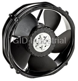
DC Fan Axial Ball Bearing 24V 16V to 36V 552.9CFM 66dB Low Noise/PWM 2214F/2TDHHO
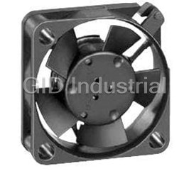
DC Fan Axial Sintec-Sleeve Bearing 12V 10V to 14V 1.9CFM 15dB 25 X 25 X 8mm Low Power Consumption 25...
DC Fan Axial Sintec-Sleeve Bearing 5V 4.5V to 5.5V 2.7CFM 23dB 25 X 25 X 8mm Low Power Consumption 2...
DC Fan Axial Sintec-Sleeve Bearing 5V 4.5V to 5.5V 1.2CFM 5dB 25 X 25 X 8mm Low Power Consumption 25...
DC Fan Axial Sintec-Sleeve Bearing 5V 4.5V to 5.5V 1.9CFM 16dB 25 X 25 X 8mm Low Power Consumption 2...
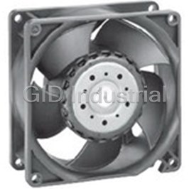
DC Fan Axial Ball Bearing 12V 6V to 13.8V 140CFM 69dB 92 X 92 X 38mm 3212J/2H3
Request a Quote

The quote request has been received
Close

Facing challenges or have inquiries? Feel free to contact us!
Call Us +1-469-283-2440
What they say about us
FANTASTIC RESOURCE
One of our top priorities is maintaining our business with precision, and we are constantly looking for affiliates that can help us achieve our goal. With the aid of GID Industrial, our obsolete product management has never been more efficient. They have been a great resource to our company, and have quickly become a go-to supplier on our list!
Bucher Emhart Glass
EXCELLENT SERVICE
With our strict fundamentals and high expectations, we were surprised when we came across GID Industrial and their competitive pricing. When we approached them with our issue, they were incredibly confident in being able to provide us with a seamless solution at the best price for us. GID Industrial quickly understood our needs and provided us with excellent service, as well as fully tested product to ensure what we received would be the right fit for our company.
Fuji
HARD TO FIND A BETTER PROVIDER
Our company provides services to aid in the manufacture of technological products, such as semiconductors and flat panel displays, and often searching for distributors of obsolete product we require can waste time and money. Finding GID Industrial proved to be a great asset to our company, with cost effective solutions and superior knowledge on all of their materials, it’d be hard to find a better provider of obsolete or hard to find products.
Applied Materials
CONSISTENTLY DELIVERS QUALITY SOLUTIONS
Over the years, the equipment used in our company becomes discontinued, but they’re still of great use to us and our customers. Once these products are no longer available through the manufacturer, finding a reliable, quick supplier is a necessity, and luckily for us, GID Industrial has provided the most trustworthy, quality solutions to our obsolete component needs.
Nidec Vamco
TERRIFIC RESOURCE
This company has been a terrific help to us (I work for Trican Well Service) in sourcing the Micron Ram Memory we needed for our Siemens computers. Great service! And great pricing! I know when the product is shipping and when it will arrive, all the way through the ordering process.
Trican Well Service
GO TO SOURCE
When I can't find an obsolete part, I first call GID and they'll come up with my parts every time. Great customer service and follow up as well. Scott emails me from time to time to touch base and see if we're having trouble finding something.....which is often with our 25 yr old equipment.
ConAgra Foods