

 Manufacturers
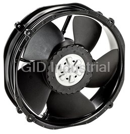
EBM-PAPST INC. A2E200-AF02-02

Description
AC Fan Axial Bearing 230V 435.55CFM/488.52CFM 65dB/69dB
A2E200-AF02-02
Part Number
A2E200-AF02-02
Price
Request Quote
Manufacturer
EBM-PAPST INC.
Lead Time
Request Quote
Category
Thermal Management » Blowers and Fans
Specifications
Manufacturer
ebm-papst Inc.
Manufacturers Part #
A2E200-AF02-02
Industry Aliases
A2E200-AF02-02
Sub-Category
Thermal Management Blowers and Fans
Factory Pack Quantity
1
Datasheet

Extracted Text
A2E200-AF02-02 Operating instructions ebm-papst Mulfingen GmbH & Co. KG 1. SAFETY REGULATIONS AND NOTES Bachmühle 2 Please read these operating instructions carefully before starting to work D-74673 Mulfingen with the device. Observe the following warnings to prevent malfunctions Phone +49 (0) 7938 81-0 or physical damage to both property and people. Fax +49 (0) 7938 81-110 These operating instructions are to be regarded as part of this device. info1@de.ebmpapst.com If the device is sold or transferred, the operating instructions must www.ebmpapst.com accompany it. CONTENTS These operating instructions may be duplicated and forwarded for information about potential dangers and their prevention. 1. SAFETY REGULATIONS AND NOTES 1 1.1 Levels of hazard warnings 1.1 Levels of hazard warnings 1 These operating instructions use the following hazard levels to indicate 1.2 Staff qualification 1 1.3 Basic safety rules 1 potentially hazardous situations and important safety regulations: 1.4 Electrical voltage 1 DANGER 1.5 Safety and protective functions 2 Indicates an imminently hazardous situation which, if not 1.6 Mechanical movement 2 avoided, will result in death or serious injury. Compliance with 1.7 Emission 2 the measures is mandatory. 1.8 Hot surface 2 1.9 Transport 2 WARNING Indicates a potentially hazardous situation which, if not avoided, 1.10 Storage 2 could result in death or serious injury. Exercise extreme 2. PROPER USE 3 caution while working. CAUTION 3. TECHNICAL DATA 4 Indicates a potentially hazardous situation which, if not avoided, 3.1 Product drawing 4 may result in minor or moderate injury or damage of property. 3.2 Nominal data 5 3.3 Technical features 5 NOTE 3.4 Mounting data 5 A potentially harmful situation can occur and, if not avoided, can 3.5 Transport and storage conditions 5 lead to property damage. 4. CONNECTION AND START-UP 6 1.2 Staff qualification 4.1 Connecting the mechanical system 6 The device may only be transported, unpacked, installed, operated, 4.2 Connecting the electrical system 6 maintained and otherwise used by qualified, trained and authorised 4.3 Connection of the cables 6 technical staff. 4.4 Connection screen 8 Only authorised specialists are permitted to install the device, to carry 4.5 Checking the connections 9 out a test run and to perform work on the electrical installation. 4.6 Switch on device 9 4.7 Switching off the device 9 1.3 Basic safety rules 5. MAINTENANCE, MALFUNCTIONS, POSSIBLE 9 Any safety hazards stemming from the device must be re-evaluated CAUSES AND REMEDIES once it is installed in the end device. 5.1 Cleaning 10 The local industrial safety regulations must always be observed when 5.2 Safety test 10 working on the device. 5.3 Disposal 10 Keep the workplace clean and tidy. Untidiness in the working area increases the risk of injury. Observe the following when working on the unit: ; Do not make any modifications, additions or conversions to the device without the approval of ebm-papst. 1.4 Electrical voltage ; Check the electrical equipment of the device at regular intervals, refer to chapter 5.2 Safety test. ; Replace loose connections and defective cables immediately. DANGER Electrical load on the device Risk of electric shock → Stand on a rubber mat if you are working on an electrically charged device. Item no. 10833-5-9970 · ENG · Revision 96928 · Release 2017-10-26 · Page 1 / 10 ebm-papst Mulfingen GmbH & Co. KG · Bachmühle 2 · D-74673 Mulfingen · Phone +49 (0) 7938 81-0 · Fax +49 (0) 7938 81-110 · info1@de.ebmpapst.com · www.ebmpapst.com Translation of the original operating instructions A2E200-AF02-02 Operating instructions CAUTION → Do not wear any loose-fitting or dangling clothing or jewellery Electrical load on the capacitor after device is switched off while working on rotating parts.# Protect long hair with a cap. Electric shock, risk of injury 1.7 Emission → Discharge the capacitors before working on the device. WARNING WARNING Depending on the installation and operating conditions, Terminals and connections have voltage even with a a sound pressure level greater than 70 dB(A) may arise. unit that is shut off Danger of noise-induced hearing loss Electric shock → Take appropriate technical safety measures. → Wait five minutes after disconnecting the voltage at all poles before opening the device. → Protect operating personnel with appropriate safety equipment, e.g. hearing protection. CAUTION → Also observe the requirements of local agencies. In the event of failure, there is electric voltage at the rotor and impeller 1.8 Hot surface The rotor and impeller are base insulated. → Do not touch the rotor and impeller once they are installed. CAUTION High temperature at the motor housing CAUTION Danger of burn injuries The motor restarts automatically when operating voltage → Ensure that sufficient protection against accidental contact is is applied, e.g. after a power failure. provided. Danger of injury → Keep out of the danger zone of the device. 1.9 Transport → When working on the device, switch off the mains NOTE supply voltage and secure the latter from being switched on Transport of device again. → Wait until the device stops. → Transport the device in its original packaging only. → Secure the device so that it does not slip, e.g. by using a 1.5 Safety and protective functions clamping strap. DANGER 1.10 Storage Protective device missing and protective device not functioning ; Store the device, partially or fully assembled, in the original Without a protective device there is a risk of serious injury, for packaging in a clean, dry and weatherproof place free of vibrations. instance when reaching into the device during operation. ; Protect the device against environmental effects and dirt until final installation. → Operate the device only with a fixed protective device and guard grille.# The fixed protective device must be able to ; We recommend storing the device for no longer than one year in withstand the kinetic energy of a fan blade that becomes order to guarantee trouble-free operation and longest possible service detached at maximum speed. There must not be any gaps life. which it is possible to reach into with the fingers, for example. ; Even devices explicitly intended for outdoor use are to be stored as → The device is a built-in component. As the operator, you described prior to commissioning. are responsible for ensuring that the device is secured ; Maintain the storage temperature, see adequately. chapter 3.5 Transport and storage conditions. → Stop the device immediately if a protective device is found to be missing or ineffective. 1.6 Mechanical movement DANGER Rotating device Body parts that come into contact with the rotor and impeller can be injured. → Secure the device against accidental contact. → Before working on the system/machine, wait until all parts have come to a standstill. WARNING Rotating device Long hair, dangling items of clothing, jewellery and similar items can become entangled and be pulled into the device. Risk of injury. Item no. 10833-5-9970 · ENG · Revision 96928 · Release 2017-10-26 · Page 2 / 10 ebm-papst Mulfingen GmbH & Co. KG · Bachmühle 2 · D-74673 Mulfingen · Phone +49 (0) 7938 81-0 · Fax +49 (0) 7938 81-110 · info1@de.ebmpapst.com · www.ebmpapst.com Translation of the original operating instructions A2E200-AF02-02 Operating instructions 2. PROPER USE The device is exclusively designed as a built-in device for conveying air according to its technical data. Any other usage above and beyond this does not conform with the intended purpose and constitutes misuse of the device. Customer equipment must be capable of withstanding the mechanical and thermal stresses that can arise from this product. This applies for the entire service life of the equipment in which this product is installed. Proper use also includes: ● Conveying of air at an ambient air pressure of 800 mbar to 1050 mbar. ● Using the device within the permitted ambient temperature range; see chapter 3.5 Transport and storage conditions and chapter 3.2 Nominal data. ● Operating the device with all protective devices. ● Observance of the operating instructions. Improper use Using the device in the following ways is particularly prohibited and may cause hazards: ● Operating the device with an imbalance, e.g. caused by dirt deposits or icing. ● Resonance mode, operation with heavy vibrations. These also include vibrations that are transmitted from the customer system to the fan. ● Moving air that contains abrasive particles. ● Moving highly corrosive air, e.g. salt spray mist. Exceptions are devices that are intended for salt spray mist and protected accordingly. ● Moving air that contains dust pollution, e.g. suctioning off saw dust. ● Operating the device close to flammable materials or components. ● Operating the device in an explosive atmosphere. ● Using the device as a safety component or for taking on safety- related functions. ● Operation with completely or partially disassembled or modified protective features. ● In addition, all application options that are not listed under proper use. Item no. 10833-5-9970 · ENG · Revision 96928 · Release 2017-10-26 · Page 3 / 10 ebm-papst Mulfingen GmbH & Co. KG · Bachmühle 2 · D-74673 Mulfingen · Phone +49 (0) 7938 81-0 · Fax +49 (0) 7938 81-110 · info1@de.ebmpapst.com · www.ebmpapst.com Translation of the original operating instructions A2E200-AF02-02 Operating instructions 3. TECHNICAL DATA 3.1 Product drawing All measures have the unit mm. 1 Direction of air flow "A" 2 Thread reach max. 5 mm 3 Connection line PVC 4G 0.5 mm², 4x lead tips crimped Item no. 10833-5-9970 · ENG · Revision 96928 · Release 2017-10-26 · Page 4 / 10 ebm-papst Mulfingen GmbH & Co. KG · Bachmühle 2 · D-74673 Mulfingen · Phone +49 (0) 7938 81-0 · Fax +49 (0) 7938 81-110 · info1@de.ebmpapst.com · www.ebmpapst.com Translation of the original operating instructions A2E200-AF02-02 Operating instructions For cyclic speed loads, note that the rotating parts of the device 3.2 Nominal data are designed for maximum one million load cycles. If you have Motor M2E068-CA specific questions, contact ebm-papst for support. ; Use the device in accordance with its protection type. Phase 1~ 1~ Nominal voltage / VAC 230 230 Notes on surface quality Frequency / Hz 50 60 The surfaces of the products conform to the generally applicable industrial Type of data definition fa fa standard. The surface quality may vary during the production period. Strength, dimensional stability and dimensional accuracy are not affected Valid for approval / CE CE by this. standard -1 The colour pigments of the paints used react perceptibly to UV light over Speed (rpm) / min 2740 3120 the course of time. This does not however have any influence on the Power input / W 50 61 technical properties of the products. To prevent the formation of patches Current draw / A 0.24 0.28 and fading, the product is to be protected against UV radiation. Changes Motor capacitor / µF 1.5 1.5 in colour are not a reason for complaint and are not covered by the Capacitor voltage / VDB 400 400 warranty. Max. back pressure / Pa 200 200 Min. ambient -25 -25 3.4 Mounting data temperature / °C For depth of screw, see chapter 3.1 Product drawing Max. ambient 75 75 temperature / °C Strength class for 8.8 Starting current / A 0.53 0.53 mounting screws ml = Max. load · me = Max. efficiency · fa = Running at free air ; Secure the mounting screws against accidentally coming loose (e.g. cs = Customer specs · cu = Customer unit by using self-locking screws). Subject to alterations Any further mounting data required can be taken from the product 3.3 Technical features drawing or Section chapter 4.1 Connecting the mechanical system. Mass 1.4 kg 3.5 Transport and storage conditions Size 200 mm Max. permissible + 70 °C Surface of rotor Coated in black ambient motor temp. Material of blades Sheet steel, coated in black (transp./ storage) Number of blades 5 Min. permissible - 40 °C Direction of air flow "A" ambient motor temp. Direction of rotation Clockwise, seen on rotor (transp./storage) Type of protection IP 44; Depending on installation and position Insulation class "B" Humidity (F)/ H1 environmental protection class (H) Mounting position Any Condensation Rotor-side drainage holes Operation mode S1 Motor bearing Ball bearing Touch current acc. < 0.75 mA IEC 60990 (measuring network Fig. 4, TN system) Motor protection Thermal overload protector (TOP) wired internally Cable exit Variable Protection class I (if protective earth is connected by customer) Product conforming EN 60335-1; CE to standard Approval EAC; CCC Item no. 10833-5-9970 · ENG · Revision 96928 · Release 2017-10-26 · Page 5 / 10 ebm-papst Mulfingen GmbH & Co. KG · Bachmühle 2 · D-74673 Mulfingen · Phone +49 (0) 7938 81-0 · Fax +49 (0) 7938 81-110 · info1@de.ebmpapst.com · www.ebmpapst.com Translation of the original operating instructions A2E200-AF02-02 Operating instructions → Make sure that the cable end is connected in a dry 4. CONNECTION AND START-UP environment. 4.1 Connecting the mechanical system Connect the device only to circuits that can be switched off using an all-pole disconnecting switch. CAUTION Cutting and crushing hazard when removing the fan 4.2.1 Prerequisites from the packaging → Carefully remove the device from its packaging, holding it ; Check that the data on the type plate match the connection data. by the centre of the blades only. Make sure to avoid any ; If the operating capacitor is not installed by ebm-papst, check whether shock. the data of the operating capacitor match the data on the type plate. → Wear safety shoes and cut-resistant safety gloves. ; Before connecting the device, ensure that the supply voltage matches the operating voltage of the device. NOTE Damage to device from vibration ; Only use cables designed for current according to the type plate. Bearing damage, reduced service life For determining the cross-section, follow the basic principles in accordance with EN 61800-5-1. The protective earth must have a → Forces or impermissibly high vibration levels must not be cross-section equal to or greater than the outer conductor cross- transmitted to the fan from system components. #If the fan is section. connected to air ducts, it should isolated from vibrations, for We recommend the use of 105°C cables. Ensure that the minimum example using compensators or similar elements. #Fasten cable cross-section is at least the fan to the substructure without distorting it. AWG26/0.13 mm². ; Check the device for transport damage. Damaged devices must no longer be installed. Protective earth contact resistance as per EN 60335 ; Install the undamaged device according to your application. Compliance with the resistance specifications as per EN 60335 for the protective earth connection circuit must be verified in the application. CAUTION Depending on the installation situation, it may be necessary to connect Possibility of damage to the device an additional protective earth conductor by way of the extra protective Serious damage may result if the device slips during assembly. earth terminal provided on the device. → Keep the device fixed in position at the installation location until all attachment screws have been tightened. 4.2.2 Voltage control ● The fan must not be strained on fastening. With open loop speed control using transformers or electronic voltage regulators (e.g. phase angle control), excessive current 4.2 Connecting the electrical system may occur. DANGER In addition, noises can occur with phase angle control Electric voltage on the device depending on the mounting situation. Electric shock 4.2.3 Frequency inverter → Always install a protective earth first. Please use a frequency converter only after consultation with ebm-papst. → Check the protective earth. For operation with frequency converters, fit sinusoidal filters that DANGER work on all poles (phase-phase and phase-earth) between the Incorrect insulation frequency converter and the motor. Risk of fatal injury from electric shock During operation with frequency converters, an all-pole sine → Use only cables that meet the specified installation filter protects the motor against high-voltage transients that can requirements for voltage, current, insulation material, load etc. destroy the winding insulation system, and against harmful → Route cables such that they cannot be touched by any bearing currents. rotating parts. Heating of the motor due to use of a frequency converter must be CAUTION checked in the application by the customer. Electrical voltage The fan is a built-in component and features no electrically 4.3 Connection of the cables isolating switch. External leads are brought out of device. → Only connect the fan to circuits that can be switched off with ; First connect the "PE" (protective earth) connection. an all-pole separating switch. ● Connect the lines according to your application. When doing so, → When working on the fan, you must switch off the observe chapter 4.4 Connection screen. installation/machine in which the fan is installed and secure it from being switched on again. NOTE Water penetration into leads or wires Water enters at the cable end on the customers side and can damage the device. Item no. 10833-5-9970 · ENG · Revision 96928 · Release 2017-10-26 · Page 6 / 10 ebm-papst Mulfingen GmbH & Co. KG · Bachmühle 2 · D-74673 Mulfingen · Phone +49 (0) 7938 81-0 · Fax +49 (0) 7938 81-110 · info1@de.ebmpapst.com · www.ebmpapst.com Translation of the original operating instructions A2E200-AF02-02 Operating instructions 4.3.1 Cable routing No water may penetrate along the cable in the direction of the cable exit. NOTE Damage caused by moisture penetration. Moisture can penetrate into the terminal box if water is constantly present at the cable glands. → To prevent the constant accumulation of water at the cable glands, the cable should be routed in a U-shaped loop (siphon) wherever possible.# If this is not possible, a drip edge can be produced by fitting a cable tie directly in front of the cable gland for example. Fans installed in upright position Fig. 1: Cable routing for fans installed in upright position. The cables must always be routed downwards. Item no. 10833-5-9970 · ENG · Revision 96928 · Release 2017-10-26 · Page 7 / 10 ebm-papst Mulfingen GmbH & Co. KG · Bachmühle 2 · D-74673 Mulfingen · Phone +49 (0) 7938 81-0 · Fax +49 (0) 7938 81-110 · info1@de.ebmpapst.com · www.ebmpapst.com Translation of the original operating instructions A2E200-AF02-02 Operating instructions 4.4 Connection screen U1 blue Z brown U2 black PE green/yellow Item no. 10833-5-9970 · ENG · Revision 96928 · Release 2017-10-26 · Page 8 / 10 ebm-papst Mulfingen GmbH & Co. KG · Bachmühle 2 · D-74673 Mulfingen · Phone +49 (0) 7938 81-0 · Fax +49 (0) 7938 81-110 · info1@de.ebmpapst.com · www.ebmpapst.com Translation of the original operating instructions A2E200-AF02-02 Operating instructions 4.5 Checking the connections 5. MAINTENANCE, MALFUNCTIONS, POSSIBLE ; Make sure that the power is off (all phases). CAUSES AND REMEDIES ; Secure it from being switched on again. Do not perform any repairs on your device. Return the device to ebm- ; Check the correct fit of the connection lines. papst for repair or replacement. WARNING 4.6 Switch on device Terminals and connections have voltage even with a The device is not to be switched on until it has been installed properly unit that is shut off and in accordance with its intended use, including the required protective Electric shock devices and professional electrical connection. This also applies to → Wait five minutes after disconnecting the voltage at all poles devices which have already been equipped with plugs and terminals or before opening the device. similar connectors by the customer. CAUTION WARNING Electrical load on the capacitor after device is switched off Hot motor housing Electric shock, risk of injury Fire hazard → Discharge the capacitors before working on the device. → Ensure that no combustible or flammable materials are CAUTION located close to the fan. The motor restarts automatically when operating voltage ; Inspect the device for visible external damage and the proper function is applied, e.g. after a power failure. of the protective features before switching it on. Danger of injury ; Check the air flow paths of the fan for foreign objects and remove any → Keep out of the danger zone of the device. that are found. → When working on the device, switch off the mains ; Apply the nominal voltage to the voltage supply. supply voltage and secure the latter from being switched on NOTE again. Damage to device by vibrations → Wait until the device stops. Bearing damage, reduced service life If the device remains out of use for some time, e.g. when in → The fan must operate free of vibrations throughout its speed storage, we recommend switching the device on for at least control range. #Strong vibrations can result from improper two hours to allow any condensate to evaporate and to move handling, imbalance resulting from damage during transport, the bearings. or component-induced or structural resonances. #When putting the fan into service, determine the speed ranges with Malfunction/error Possible cause Possible remedy excessive vibration levels and also any resonance Impeller running Imbalance in rotating Clean the device; if frequencies that may be present. #When regulating the roughly parts imbalance is still speed, pass through resonance ranges as quickly as evident after cleaning, possible or find another remedy.# Operation at excessive replace the device. vibration levels can lead to premature failure. If you have attached any weight 4.7 Switching off the device clips during cleaning, make sure to remove ; Disconnect the device from the supply voltage at the main switch for them afterwards. the supply line. Motor does not turn Mechanical blockage Switch off, de- ; When disconnecting, be sure to disconnect the earth wire connection energise, and last. remove mechanical blockage. Mains supply voltage Check mains supply faulty voltage, restore power supply. Faulty connection De-energise, correct connection, see connection diagram. Thermal overload Allow motor to cool protector responded off, locate and rectify cause of error, if necessary cancel restart lock-out Unacceptable Check operating point operating point Overtemperature of Ambient temperature Lower ambient motor too high temperature if possible Item no. 10833-5-9970 · ENG · Revision 96928 · Release 2017-10-26 · Page 9 / 10 ebm-papst Mulfingen GmbH & Co. KG · Bachmühle 2 · D-74673 Mulfingen · Phone +49 (0) 7938 81-0 · Fax +49 (0) 7938 81-110 · info1@de.ebmpapst.com · www.ebmpapst.com Translation of the original operating instructions A2E200-AF02-02 Operating instructions Insufficient cooling Improve cooling 5.3.1 Country-specific legal requirements NOTE If you have any other problems, contact ebm-papst. Country-specific legal requirements Always observe the applicable country-specific legal regulations with regard to the disposal of products or waste 5.1 Cleaning occurring in the various phases of the life cycle. The corresponding disposal standards are also to be heeded. NOTE Damage to the device during cleaning 5.3.2 Disassembly Malfunction possible Disassembly of the product must be performed or supervised by → Do not clean the device using a water jet or high-pressure qualified personnel with the appropriate technical knowledge. cleaner.# Do not use any acid, alkali or solvent- The product is to be disassembled into suitable components for disposal basedcleaning agents.# Do not use any pointed or sharp- employing standard procedures for motors. edged objects for cleaning WARNING 5.2 Safety test Heavy parts of the product may drop off. Some of the product components are heavy. These components What has to How to test? Frequency Which could drop off during disassembly. be tested? measure? This can result in fatal or serious injury and material damage. Check the Visual inspection At least every Repair or → Secure components before unfastening to stop them falling. protective 6 months replacement of casing against the device 5.3.3 Component disposal accidental The products are mostly made of steel, copper, aluminium and plastic. contact for Metallic materials are generally considered to be fully recyclable. damage and to Separate the components for recycling into the following categories: ensure that it is intact ● Steel and iron Check the Visual inspection At least every Replacement of ● Aluminium device for 6 months the device ● Non-ferrous metal, e.g. motor windings damage to ● Plastics, particularly with brominated flame retardants, in accordance blades and with marking housing Mounting the Visual inspection At least every Fasten ● Insulating materials connection lines 6 months ● Cables and wires Mounting of Visual inspection At least every Fasten ● Electronic scrap, e.g. circuit boards protective earth 6 months Only ferrite magnets and not rare earth magnets are used in external connection rotor motors from ebm-papst Mulfingen GmbH & Co. KG. Check the Visual inspection At least every Replace wires insulation of the 6 months ; Ferrite magnets can be disposed of in the same way as normal iron wires for damage and steel. Condensate Visual inspection At least every Open bore holes Electrical insulating materials on the product, in cables and wires are discharge holes 6 months made of similar materials and are therefore to be treated in the same for clogging, as manner. necessary The materials concerned are as follows: Weld seams for Visual inspection At least every Replace device ● Miscellaneous insulators used in the terminal box crack formation 6 months ● Power lines Abnormal acoustic At least every Replace device ● Cables for internal wiring bearing noise 6 months ● Electrolytic capacitors 5.3 Disposal Dispose of electronic components employing the proper procedures for electronic scrap. For ebm-papst, environmental protection and resource preservation are top priority corporate goals. → Please contact ebm-papst for any other questions on disposal. ebm-papst operates an environmental management system which is certified in accordance with ISO 14001 and rigorously implemented around the world on the basis of German standards. Right from the development stage, ecological design, technical safety and health protection are fixed criteria. The following section contains recommendations for ecological disposal of the product and its components. Item no. 10833-5-9970 · ENG · Revision 96928 · Release 2017-10-26 · Page 10 / 10 ebm-papst Mulfingen GmbH & Co. KG · Bachmühle 2 · D-74673 Mulfingen · Phone +49 (0) 7938 81-0 · Fax +49 (0) 7938 81-110 · info1@de.ebmpapst.com · www.ebmpapst.com Translation of the original operating instructions
Frequently asked questions
How does Electronics Finder differ from its competitors?

Is there a warranty for the A2E200-AF02-02?
Which carrier will Electronics Finder use to ship my parts?
Can I buy parts from Electronics Finder if I am outside the USA?
Which payment methods does Electronics Finder accept?
Why buy from GID?

Quality
We are industry veterans who take pride in our work

Protection
Avoid the dangers of risky trading in the gray market

Access
Our network of suppliers is ready and at your disposal

Savings
Maintain legacy systems to prevent costly downtime

Speed
Time is of the essence, and we are respectful of yours
Related Products
DC Fan Axial Ball Bearing 24V 16V to 36V 552.9CFM 66dB Low Noise/PWM 2214F/2TDHHO
DC Fan Axial Sintec-Sleeve Bearing 12V 10V to 14V 1.9CFM 15dB 25 X 25 X 8mm Low Power Consumption 25...
DC Fan Axial Sintec-Sleeve Bearing 5V 4.5V to 5.5V 2.7CFM 23dB 25 X 25 X 8mm Low Power Consumption 2...
DC Fan Axial Sintec-Sleeve Bearing 5V 4.5V to 5.5V 1.2CFM 5dB 25 X 25 X 8mm Low Power Consumption 25...
DC Fan Axial Sintec-Sleeve Bearing 5V 4.5V to 5.5V 1.9CFM 16dB 25 X 25 X 8mm Low Power Consumption 2...
DC Fan Axial Ball Bearing 12V 6V to 13.8V 140CFM 69dB 92 X 92 X 38mm 3212J/2H3
Request a Quote

The quote request has been received
Close

Facing challenges or have inquiries? Feel free to contact us!
Call Us +1-469-283-2440
What they say about us
FANTASTIC RESOURCE
One of our top priorities is maintaining our business with precision, and we are constantly looking for affiliates that can help us achieve our goal. With the aid of GID Industrial, our obsolete product management has never been more efficient. They have been a great resource to our company, and have quickly become a go-to supplier on our list!
Bucher Emhart Glass
EXCELLENT SERVICE
With our strict fundamentals and high expectations, we were surprised when we came across GID Industrial and their competitive pricing. When we approached them with our issue, they were incredibly confident in being able to provide us with a seamless solution at the best price for us. GID Industrial quickly understood our needs and provided us with excellent service, as well as fully tested product to ensure what we received would be the right fit for our company.
Fuji
HARD TO FIND A BETTER PROVIDER
Our company provides services to aid in the manufacture of technological products, such as semiconductors and flat panel displays, and often searching for distributors of obsolete product we require can waste time and money. Finding GID Industrial proved to be a great asset to our company, with cost effective solutions and superior knowledge on all of their materials, it’d be hard to find a better provider of obsolete or hard to find products.
Applied Materials
CONSISTENTLY DELIVERS QUALITY SOLUTIONS
Over the years, the equipment used in our company becomes discontinued, but they’re still of great use to us and our customers. Once these products are no longer available through the manufacturer, finding a reliable, quick supplier is a necessity, and luckily for us, GID Industrial has provided the most trustworthy, quality solutions to our obsolete component needs.
Nidec Vamco
TERRIFIC RESOURCE
This company has been a terrific help to us (I work for Trican Well Service) in sourcing the Micron Ram Memory we needed for our Siemens computers. Great service! And great pricing! I know when the product is shipping and when it will arrive, all the way through the ordering process.
Trican Well Service
GO TO SOURCE
When I can't find an obsolete part, I first call GID and they'll come up with my parts every time. Great customer service and follow up as well. Scott emails me from time to time to touch base and see if we're having trouble finding something.....which is often with our 25 yr old equipment.
ConAgra Foods