

 Manufacturers
EBM-PAPST INC. W3G250-CC54-01

Description
AC Fans EC Axial/250mm Round Round Nozzle/"V"Flow
Part Number
W3G250-CC54-01
Price
Request Quote
Manufacturer
EBM-PAPST INC.
Lead Time
Request Quote
Category
Thermal Management » Blowers and Fans
Specifications
Manufacturer
ebm-papst Inc.
Manufacturers Part #
W3G250-CC54-01
Lead Time
On Order with Factory
Sub-Category
Thermal Management Blowers and Fans
Factory Pack Quantity
1
Datasheet


Extracted Text
EC axial fans S series EC axial fans, S series, 24 / 48 VDC Ø 200 - Ø 300 186 EC axial fans, S series, mains-powered Ø 250 - Ø 990 198 185 EC axial AC axial AC axial AC axial General Contacts Technology Accessories EC-SYSTEMS ESM Q-motor EC axial fans AC axial fans S series A series K series S series information EC axial fans 24 /48 VDC S series, Ø 200 – Material: Guard grille: Steel, phosphated and coated in black plastic Wall ring: Sheet steel, pre-galvanised and coated in black plastic Blades: Sheet steel, coated in black Rotor: Coated in black – Number of blades: 9 – Direction of rotation: Counter-clockwise, seen on rotor – Type of protection: IP 42 – Insulation class: "B" – Mounting position: Any – Condensate discharges: None – Mode of operation: Continuous operation (S1) – Bearings: Maintenance-free ball bearings Nominal data 3 Type Motor VDC VDC m /h rpm W A dB(A) Pa °C kg p. 420 A *1G 200 M1G 074-BF 24 16-28 1090 2950 55 2.60 60 — -25 to +60 1.5 G) A *1G 200 M1G 074-BF 48 36-57 1005 2750 45 1.10 60 — -25 to +60 1.5 G) subject to alterations n P Lp � 1 A tL Curves (established at 24 VDC) [rpm] [W] [dB(A)] [%] A 1’ 2300 73 63 — A A 2’ 2970 77 62 67 A 3’ 3100 80 63 64 A 4’ 2970 80 66 54 240 A 1 2950 55 60 — A 2 2890 58 60 67 200 A 3 2800 61 61 64 A 4 2780 63 64 54 A 5 2270 27 55 — 160 U R A 6 2230 28 54 67 A 7 2170 29 54 64 U N 120 A 8 4' 2130 30 57 54 4 3' 3 80 8 2' 7 40 2 6 1 1' 5 0 200 400 600 [CFM] 3 200 400 600 800 1000 [m /h] 186 [Pa] 0,2 0,4 0,6 0,8 1,0 [in H O] 2 Curve Nominal voltage Voltage range Air flow Speed/rpm Power input Current draw Sound pressure level Max. operative range Perm. amb. temp. Mass without attachments Electr. connection – Technical features: • Tach output • Control input 0-10 VDC / PWM • Polarity and locked rotor protection – EMC: Interference emission acc. to EN 61000-6-3 Interference immunity acc. to EN 61000-6-2 – Cable exit: Variable – Protection class: I – Product conforming to standard: EN 60950-1 – Approvals: UL, CSA � "V"/ "A" �� "V"/ "A" �� "V"/ "A" �� "V"/ "A" � Without With full With guard grille With guard grille (1) attachments round nozzle for full nozzle for short nozzle "V" A1G 200-AH77 -52 W1G 200-CH77 -52 S1G 200-BH77 -52 S1G 200-AH77 -52 "A" A1G 200-AI77 -52 W1G 200-CI77 -52 S1G 200-BI77 -52 S1G 200-AI77 -52 "V" A1G 200-AH01 -52 W1G 200-CH01 -52 S1G 200-BH01 -52 S1G 200-AH01 -52 "A" A1G 200-AI01 -52 W1G 200-CI01 -52 S1G 200-BI01 -52 S1G 200-AI01 -52 (1) Increased noise levels in "V" direction of air flow 187 Drawings Guard grille Wall ring Electr. connection p. 188 f. p. 362 f. p. 372 f. p. 420 Direction of air flow EC axial AC axial AC axial AC axial General Contacts Technology Accessories EC-SYSTEMS ESM Q-motor EC axial fans AC axial fans S series A series K series S series information EC axial fans 24 /48 VDC S series, Ø 200, drawings of directions of air flow "V" and "A" Type Without attachments A1G 200-AH77 -52 "V" Depth of screw "A" A1G 200-AI77 -52 max. 6 mm ±5 17 A1G 200-AH01 -52 "V" ±3 "A" 35 A1G 200-AI01 -52 M4 Brass lead tips 6 85 +20 450 ±1 65 � "V" "A" � Type With full round nozzle W1G 200-CH77 -52 "V" W1G 200-CI77 -52 "A" 9 80 "V" 5 W1G 200-CH01 -52 W1G 200-CI01 -52 "A" � "V" "A" � Type With guard grille for full nozzle S1G 200-BH77 -52 "V" "A" S1G 200-BI77 -52 S1G 200-BH01 -52 "V" 3,9 4,6 S1G 200-BI01 -52 "A" � "V" "A" � 188 15˚ ±0,15 58 6x60˚ 250 7 1,25 Ø200 Ø280 Ø92 Ø197 -2 32,7 245 Type With guard grille for short nozzle S1G 200-AH77 -52 "V" "A" S1G 200-AI77 -52 23 S1G 200-AH01 -52 "V" ±5 6,5 13 "A" S1G 200-AI01 -52 3,9 46 � "V" "A" � 189 260 EC axial AC axial AC axial AC axial General Contacts Technology Accessories EC-SYSTEMS ESM Q-motor EC axial fans AC axial fans S series A series K series S series information EC axial fans 24 /48 VDC S series, Ø 250 – Material: Guard grille: Steel, phosphated and coated in black plastic Wall ring: Sheet steel, pre-galvanised and coated in black plastic Blades: Sheet steel, coated in black Rotor: Coated in black – Number of blades: 7 for direction of air flow "V", 9 for direction of air flow "A" – Direction of rotation: Counter-clockwise, seen on rotor – Type of protection: IP 42 – Insulation class: "B" – Mounting position: Any – Condensate discharges: None – Mode of operation: Continuous operation (S1) – Bearings: Maintenance-free ball bearings Nominal data 3 Type Motor VDC VDC m /h rpm W A dB(A) Pa °C kg p. 420 A *1G 250 M1G 074-BF 24 16-28 1920 2750 105 5.00 70 — -25 to +60 1.6 G) A *1G 250 M1G 074-BF 48 36-57 1920 2750 105 2.60 70 — -25 to +60 1.6 G) subject to alterations n P Lp � 1 A tL Curves [rpm] [W] [dB(A)] [%] A 1’ 2920 129 71 — A A 2’ 2800 132 72 63 240 A 3’ 2680 135 71 60 A 4’ 2600 139 73 45 200 A 1 2750 105 70 — U R A 2 2630 110 69 63 A 3 2520 111 69 60 160 A 4 2440 114 71 45 A 5 2610 73 66 — 4' UN A 6 2320 75 67 63 4 120 A 7 2230 78 67 60 A 8 2170 80 68 45 8 3' 80 3 7 2' 2 40 6 5 1 1' 0 400 800 [CFM] 3 400 800 1200 1600 [m /h] 190 [Pa] 0,2 0,4 0,6 0,8 [in H O] 2 Curve Nominal voltage Voltage range Air flow Speed/rpm Power input Current draw Sound pressure level Max. operative range Perm. amb. temp. Mass without attachments Electr. connection – Technical features: • Tach output • Control input 0-10 VDC / PWM • Polarity and locked rotor protection – EMC: Interference emission acc. to EN 61000-6-3 Interference immunity acc. to EN 61000-6-2 – Cable exit: Variable – Protection class: I – Product conforming to standard: EN 60950-1 – Approvals: UL, CSA � "V"/ "A" �� "V"/ "A" �� "V"/ "A" �� "V"/ "A" � Without With full With guard grille With guard grille (1) attachments round nozzle for full nozzle for short nozzle "V" A1G 250-AH37 -52 W1G 250-CH37 -52 S1G 250-BH37 -52 S1G 250-AH37 -52 "A" A1G 250-AI37 -52 W1G 250-CI37 -52 S1G 250-BI37 -52 S1G 250-AI37 -52 "V" A1G 250-AH67 -52 W1G 250-CH67 -52 S1G 250-BH67 -52 S1G 250-AH67 -52 "A" A1G 250-AI67 -52 W1G 250-CI67 -52 S1G 250-BI67 -52 S1G 250-AI67 -52 (1) Increased noise levels in "V" direction of air flow 191 Drawings Guard grille Wall ring Electr. connection p. 192 f. p. 362 f. p. 372 f. p. 420 Direction of air flow EC axial AC axial AC axial AC axial General Contacts Technology Accessories EC-SYSTEMS ESM Q-motor EC axial fans AC axial fans S series A series K series S series information EC axial fans 24 /48 VDC S series, Ø 250, drawings of directions of air flow "V" and "A" Type Without attachments A1G 250-AH37 -52 "V" Depth of screw "A" A1G 250-AI37 -52 max. 6 mm ±5 21 A1G 250-AH67 -52 "V" ±3 "A" 35 A1G 250-AI67 -52 M4 Brass lead tips 6 85 +20 450 ±1 65 � "V" "A" � Type With full round nozzle W1G 250-CH37 -52 "V" W1G 250-CI37 -52 "A" 9 87 "V" 6 W1G 250-CH67 -52 W1G 250-CI67 -52 "A" � "V" "A" � Type With guard grille for full nozzle S1G 250-BH37 -52 "V" "A" S1G 250-BI37 -52 S1G 250-BH67 -52 "V" 3,9 4,6 S1G 250-BI67 -52 "A" � "V" "A" � 192 15˚ ±0,15 58 6x60˚ 295 7 1,25 Ø257 Ø320 Ø92 +1 Ø251 -2 32,7 290 Type With guard grille for short nozzle S1G 250-AH37 -52 "V" "A" S1G 250-AI37 -52 27 S1G 250-AH67 -52 "V" ±5 6,5 18 "A" S1G 250-AI67 -52 3,9 45 � "V" "A" � 193 300 EC axial AC axial AC axial AC axial General Contacts Technology Accessories EC-SYSTEMS ESM Q-motor EC axial fans AC axial fans S series A series K series S series information EC axial fans 24 /48 VDC S series, Ø 300 – Material: Guard grille: Steel, phosphated and coated in black plastic Wall ring: Sheet steel, pre-galvanised and coated in black plastic Blades: Sheet steel, coated in black Rotor: Coated in black – Number of blades: 7 – Direction of rotation: Direction of air flow "V" counter-clockwise, direction of air flow "A" clockwise, seen on rotor – Type of protection: IP 42 – Insulation class: "B" – Mounting position: Any – Condensate discharges: None – Mode of operation: Continuous operation (S1) – Bearings: Maintenance-free ball bearings Nominal data 3 Type Motor VDC VDC m /h rpm W A dB(A) Pa °C kg p. 420 A *1G 300 M1G 074-CF 24 16-28 2450 1800 90 4.00 65 — -25 to +60 2.2 G) A *1G 300 M1G 074-CF 48 36-57 2450 1800 90 2.00 65 — -25 to +60 2.2 G) subject to alterations n P Lp � 1 A tL Curves [rpm] [W] [dB(A)] [%] A 1’ 1940 108 67 — A A 2’ 1850 111 66 71 A 3’ 1790 113 66 71 A 4’ 1720 116 66 60 160 A 1 1800 90 65 — A 2 1720 89 65 71 U A 3 R 1670 91 65 71 A 4 1600 93 64 60 120 A 5 1480 49 61 — 4' A 6 1440 52 62 71 U N 4 A 7 1400 55 61 71 80 A 8 1350 58 59 60 3' 8 3 7 40 2' 2 6 5 1 1' 0 400 800 1200 [CFM] 3 600 1200 1800 2400 [m /h] 194 [Pa] 0,2 0,4 0,6 [in H O] 2 Curve Nominal voltage Voltage range Air flow Speed/rpm Power input Current draw Sound pressure level Max. operative range Perm. amb. temp. Mass without attachments Electr. connection – Technical features: • Tach output • Control input 0-10 VDC / PWM • Polarity and locked rotor protection – EMC: Interference emission acc. to EN 61000-6-3 Interference immunity acc. to EN 61000-6-2 – Cable exit: Variable – Protection class: I – Product conforming to standard: EN 60950-1 – Approvals: UL, CSA � "V"/ "A" �� "V"/ "A" �� "V"/ "A" �� "V"/ "A" � Without With full With guard grille With guard grille attachments round nozzle for full nozzle for short nozzle "V" A1G 300-AE19 -54 W1G 300-CE19 -54 S1G 300-BE19 -54 S1G 300-AE19 -54 "A" A1G 300-AE19 -52 W1G 300-CE19 -52 S1G 300-BE19 -52 S1G 300-AE19 -52 "V" A1G 300-AE33 -54 W1G 300-CE33 -54 S1G 300-BE33 -54 S1G 300-AE33 -54 "A" A1G 300-AE33 -52 W1G 300-CE33 -52 S1G 300-BE33 -52 S1G 300-AE33 -52 195 Drawings Guard grille Wall ring Electr. connection p. 196 f. p. 362 f. p. 372 f. p. 420 Direction of air flow EC axial AC axial AC axial AC axial General Contacts Technology Accessories EC-SYSTEMS ESM Q-motor EC axial fans AC axial fans S series A series K series S series information EC axial fans 24 /48 VDC S series, Ø 300, drawings of directions of air flow "V" and "A" Type Without attachments c A1G 300-AE19 -54 "V" 19.7 "A" 19.2 A1G 300-AE19 -52 A1G 300-AE33 -54 "V" 19.7 "A" 19.2 A1G 300-AE33 -52 ±0,15 58 ±5 ±3 c 60 M4 Depth of screw max. 6 mm Brass lead tips 6 85 +20 450 ±1 75 � "V" "A" � Type With full round nozzle W1G 300-CE19 -54 "V" W1G 300-CE19 -52 "A" 80 "V" W1G 300-CE33 -54 11 W1G 300-CE33 -52 "A" � "V" "A" � Type With guard grille for full nozzle S1G 300-BE19 -54 "V" "A" S1G 300-BE19 -52 S1G 300-BE33 -54 "V" 3,9 4,6 S1G 300-BE33 -52 "A" � "V" "A" � 196 6x60˚ 380 9 15˚ Ø326 Ø397 Ø92 -2 Ø300 31 4x90˚ 360 Type With guard grille for short nozzle S1G 300-AE19 -54 "V" "A" S1G 300-AE19 -52 S1G 300-AE33 -54 "V" 50 "A" 4,5 4,3 S1G 300-AE33 -52 � "V" "A" � 197 360 EC axial AC axial AC axial AC axial General Contacts Technology Accessories EC-SYSTEMS ESM Q-motor EC axial fans AC axial fans S series A series K series S series information EC axial fans mains-powered S series, Ø 250 – Material: Guard grille: Steel, phosphated and coated in black plastic Wall ring: Sheet steel, pre-galvanised and coated in black Blades: Sheet steel, coated in black Rotor: Coated in black Electronics enclosure: Die-cast aluminium, coated in black – Number of blades: 7 for direction of air flow "V", 9 for direction of air flow "A" – Direction of rotation: Counter-clockwise, seen on rotor – Type of protection: IP 44 – Insulation class: "B" – Mounting position: Shaft horizontal or rotor on bottom (rotor on top on request) – Condensate discharges: Rotor-side – Mode of operation: Continuous operation (S1) – Bearings: Maintenance-free ball bearings Nominal data Type Motor VAC Hz rpm W A Pa °C kg p. 423 A *3G 250 M3G 074-CF 1~ 100-130 50/60 2850 170 2.20 170 -25 to +60 2.4 J1) B *3G 250 M3G 074-CF 1~ 200-277 50/60 3050 175 1.40 210 -25 to +60 2.4 J1) subject to alterations (1) Nominal data in operating point with maximum load and 115 or 230 VAC n P I Lp � 1 A tL Curves [rpm] [W] [A] [dB(A)] [%] A 1 2850 162 1.80 71 — A A 2 2820 158 1.90 71 84 200 A 3 2800 153 2.00 72 84 A 4 2770 144 2.00 74 79 A 5 2360 85 1.10 66 — 160 A 6 2360 91 1.20 66 77 4 A 7 2340 94 1.20 67 77 A 8 2310 95 1.20 68 70 120 A 9 1650 33 0.50 62 — A 10 1650 35 0.50 56 68 8 A 11 1650 36 0.50 58 70 3 A 12 1650 37 0.50 59 68 80 7 12 2 40 6 11 10 5 1 9 0 250 500 750 1000 1250 [CFM] 3 [m /h] 400 800 1200 1600 2000 198 [Pa] [in H O] 0,2 0,4 0,6 2 Curve Nominal voltage range Frequency Speed/rpm Max. power (1) input Max. current (1) draw Max. operative range Perm. amb. temp. Mass without attachments Electr. connection – Technical features: • Output 10 VDC max. 1.1 mA • PFC (passive) • Tach output • Control input 0-10 VDC / PWM • Over-temperature protected electronics / motor – EMC: Interference emission acc. to EN 61000-6-3 Interference immunity acc. to EN 61000-6-2 Harmonics acc. to EN 61000-3-2/3 – Leakage current: < 3.5 mA acc. to EN 60950-1 – Cable exit: Variable – Protection class: I – Product conforming to standards: EN 60335-1, EN 61800-5-1, EN 60950-1, CE – Approvals: VDE, UL, CSA, CCC, GOST are applied for � "V"/ "A" �� "V"/ "A" �� "V"/ "A" �� "V"/ "A" � Without With full With guard grille With guard grille (2) attachments round nozzle for full nozzle for short nozzle "V" A3G 250-AC71 -01 W3G 250-CC71 -01 S3G 250-BC71 -01 S3G 250-AC71 -01 "A" A3G 250-AD71 -01 W3G 250-CD71 -01 S3G 250-BD71 -01 S3G 250-AD71 -01 "V" A3G 250-AC54 -01 W3G 250-CC54 -01 S3G 250-BC54 -01 S3G 250-AC54 -01 "A" A3G 250-AD54 -01 W3G 250-CD54 -01 S3G 250-BD54 -01 S3G 250-AD54 -01 (2) Increased noise levels in "V" direction of air flow n P I Lp � 1 A tL Curves [rpm] [W] [A] [dB(A)] [%] B 1 3050 170 1.30 72 — B B 2 2970 169 1.30 73 89 200 B 3 2900 169 1.30 74 88 B 4 2820 168 1.30 75 86 4 B 5 2500 96 0.70 68 — 160 B 6 2410 94 0.70 68 86 B 7 2360 94 0.70 69 86 B 8 2300 94 0.70 69 81 120 B 9 1740 37 0.30 57 — 8 B 10 1700 37 0.30 56 75 3 B 11 1660 37 0.30 58 75 B 12 1610 37 0.30 59 72 80 7 2 12 40 6 11 10 9 5 1 0 250 500 750 1000 1250 [CFM] 3 [m /h] 400 800 1200 1600 2000 199 Drawings Guard grille Wall ring Electr. connection p. 200 f. p. 362 f. p. 372 f. p. 423 Direction of air flow [Pa] [in H O] 0,2 0,4 0,6 2 EC axial AC axial AC axial AC axial General Contacts Technology Accessories EC-SYSTEMS ESM Q-motor EC axial fans AC axial fans S series A series K series S series information 45˚ EC axial fans mains-powered S series, Ø 250, drawings of directions of air flow "V" and "A" Type Without attachments A3G 250-AC71 -01 "V" "A" A3G 250-AD71 -01 (1) 105,2±1 M4 A3G 250-AC54 -01 "V" (2) 21±3 M4 "A" A3G 250-AD54 -01 (3) 32,5±0,5 M4 3±0,2 35±3 Core-end sleeve � "V" (1) Depth of screw max. 8 mm (pilot hole for self-tapping thread) "A" � (2) Depth of screw max. 6 mm (pilot hole for self-tapping thread) (3) Depth of screw 8-10 mm Type With full round nozzle W3G 250-CC71 -01 "V" W3G 250-CD71 -01 "A" 94,4±2 7 "V" W3G 250-CC54 -01 86,5±2 W3G 250-CD54 -01 "A" 6 � "V" "A" � Type With guard grille for full nozzle S3G 250-BC71 -01 "V" "A" S3G 250-BD71 -01 S3G 250-BC54 -01 "V" 33,25±1 55,25±3 4,2 S3G 250-BD54 -01 "A" 5 � "V" "A" � 200 295 8 85 450+20 Ø58 Ø90 Ø125 6x60˚ 15˚ Ø320±1 Ø133±0,3 Ø250±1 Ø115,3 Ø250±1 Ø92,1 Ø257±1 +1 Ø251-2 Ø290±1,5 4x90˚ Type With guard grille for short nozzle S3G 250-AC71 -01 "V" "A" S3G 250-AD71 -01 71,25±2 17,25±3 6,2 S3G 250-AC54 -01 "V" 38±1,5 "A" S3G 250-AD54 -01 5 � "V" "A" � 201 Ø281±1 Ø300±1,5 EC axial AC axial AC axial AC axial General Contacts Technology Accessories EC-SYSTEMS ESM Q-motor EC axial fans AC axial fans S series A series K series S series information EC axial fans mains-powered S series, Ø 300 – Material: Guard grille: Steel, phosphated and coated in black plastic Wall ring: Sheet steel, pre-galvanised and coated in black Blades: Sheet steel, coated in black Rotor: Coated in black Electronics enclosure: Die-cast aluminium, coated in black – Number of blades: 5 – Direction of rotation: Dir. of air flow "V" counter-clockwise, "A" clockwise, seen on rotor – Type of protection: IP 44 – Insulation class: "B" – Mounting position: Shaft horizontal or rotor on bottom (rotor on top on request) – Condensate discharges: Rotor-side – Mode of operation: Continuous operation (S1) – Bearings: Maintenance-free ball bearings Nominal data Type Motor VAC Hz rpm W A Pa °C kg p. 423 A *3G 300 M3G 074-CF 1~ 100-130 50/60 1790 125 1.70 110 -25 to +60 2.7 J1) B *3G 300 M3G 074-CF 1~ 200-277 50/60 1710 110 0.70 110 -25 to +60 2.7 J1) subject to alterations (1) Nominal data in operating point with maximum load and 115 or 230 VAC n P I Lp � 1 A tL Curves [rpm] [W] [A] [dB(A)] [%] A 1 1790 92 1.20 64 — A A 2 1770 98 1.30 64 62 A 3 1750 101 1.30 63 66 100 A 4 1720 106 1.40 62 67 A 5 1460 50 0.70 58 — 4 A 6 1430 53 0.70 58 61 80 A 7 1420 55 0.80 57 67 A 8 1400 58 0.80 56 65 A 9 1030 21 0.30 48 — 60 A 10 1030 22 0.30 49 52 8 3 A 11 1020 23 0.40 48 55 A 12 1010 24 0.40 46 59 40 7 12 2 20 6 11 10 9 5 1 0 250 500 750 1000 1250 [CFM] 3 400 800 1200 1600 2000 [m /h] 202 [Pa] [in H O] 0,1 0,2 0,3 0,4 2 Curve Nominal voltage range Frequency Speed/rpm Max. power (1) input Max. current (1) draw Max. operative range Perm. amb. temp. Mass without attachments Electr. connection – Technical features: • Output 10 VDC max. 1.1 mA • PFC (passive) • Tach output • Control input 0-10 VDC / PWM • Over-temperature protected electronics / motor – EMC: Interference emission acc. to EN 61000-6-3 Interference immunity acc. to EN 61000-6-2 Harmonics acc. to EN 61000-3-2/3 – Leakage current: < 3.5 mA acc. to EN 60950-1 – Cable exit: Variable – Protection class: I – Product conforming to standards: EN 60335-1, EN 61800-5-1, EN 60950-1, CE – Approvals: VDE, UL, CSA, CCC, GOST are applied for � "V"/ "A" �� "V"/ "A" �� "V"/ "A" �� "V"/ "A" � Without With full With guard grille With guard grille attachments round nozzle for full nozzle for short nozzle "V" A3G 300-AB77 -01 W3G 300-CB77 -01 S3G 300-BB77 -01 S3G 300-AB77 -01 "A" A3G 300-AB77 -02 W3G 300-CB77 -02 S3G 300-BB77 -02 S3G 300-AB77 -02 "V" A3G 300-AB56 -01 W3G 300-CB56 -01 S3G 300-BB56 -01 S3G 300-AB56 -01 "A" A3G 300-AB56 -02 W3G 300-CB56 -02 S3G 300-BB56 -02 S3G 300-AB56 -02 n P I Lp � 1 A tL Curves [rpm] [W] [A] [dB(A)] [%] B 1 1710 76 0.60 62 — B B 2 1680 81 0.60 62 64 B 3 1670 85 0.60 62 66 100 B 4 1650 89 0.70 60 69 B 5 1410 49 0.40 56 — B 6 1390 52 0.40 57 57 80 B 7 1345 54 0.50 56 61 4 B 8 1375 57 0.50 55 61 B 9 1000 21 0.20 47 — 60 B 10 990 22 0.20 48 54 B 11 990 23 0.20 46 58 8 B 12 980 24 0.20 45 60 3 40 7 12 2 20 6 11 10 9 5 1 0 250 500 750 1000 1250 [CFM] 3 400 800 1200 1600 2000 [m /h] 203 Drawings Guard grille Wall ring Electr. connection p. 204 f. p. 362 f. p. 372 f. p. 423 Direction of air flow [Pa] [in H O] 0,1 0,2 0,3 0,4 2 EC axial AC axial AC axial AC axial General Contacts Technology Accessories EC-SYSTEMS ESM Q-motor EC axial fans AC axial fans S series A series K series S series information 45˚ EC axial fans mains-powered S series, Ø 300, drawings of directions of air flow "V" and "A" Type Without attachments c A3G 300-AB77 -01 "V" 16.5 "A" 16.0 A3G 300-AB77 -02 (1) 105,2±1 M4 A3G 300-AB56 -01 "V" 16.5 (2) c±3 M4 "A" 16.0 A3G 300-AB56 -02 (3) M4 32,5±0,5 3±0,2 60±3 Core-end sleeve � "V" (1) Depth of screw max. 8 mm (pilot hole for self-tapping thread) "A" � (2) Depth of screw max. 6 mm (pilot hole for self-tapping thread) (3) Depth of screw 8-10 mm Type With full round nozzle W3G 300-CB77 -01 "V" W3G 300-CB77 -02 "A" "V" W3G 300-CB56 -01 W3G 300-CB56 -02 "A" � "V" "A" � Type With guard grille for full nozzle S3G 300-BB77 -01 "V" "A" S3G 300-BB77 -02 S3G 300-BB56 -01 "V" 33,25±1 75,75±3 4,2 S3G 300-BB56 -02 "A" 5 � "V" "A" � 204 85 450+20 8 Ø58 Ø90 Ø125 Ø133±0,3 Ø115,3 Ø330±1 Ø92,1 Ø300-2 Ø360±1,5 4x90˚ Type With guard grille for short nozzle S3G 300-AB77 -01 "V" "A" S3G 300-AB77 -02 S3G 300-AB56 -01 "V" "A" S3G 300-AB56 -02 � "V" "A" � 205 EC axial AC axial AC axial AC axial General Contacts Technology Accessories EC-SYSTEMS ESM Q-motor EC axial fans AC axial fans S series A series K series S series information EC axial fans mains-powered S series, Ø 315 – Material: Guard grille: Steel, phosphated and coated in black plastic Wall ring: Sheet steel, pre-galvanised and coated in black Blades: Sheet steel, coated in black Rotor: Coated in black Electronics enclosure: Die-cast aluminium, coated in black – Number of blades: 5 – Direction of rotation: Dir. of air flow "V" counter-clockwise, "A" clockwise, seen on rotor – Type of protection: IP 44 – Insulation class: "B" – Mounting position: Shaft horizontal or rotor on bottom (rotor on top on request) – Condensate discharges: Rotor-side – Mode of operation: Continuous operation (S1) – Bearings: Maintenance-free ball bearings Nominal data Type Motor VAC Hz rpm W A Pa °C kg p. 423 A *3G 315 M3G 074-CF 1~ 100-130 50/60 1670 160 2.10 110 -25 to +60 2.9 J1) B *3G 315 M3G 074-CF 1~ 200-277 50/60 1660 170 1.30 130 -25 to +60 2.9 J1) subject to alterations (1) Nominal data in operating point with maximum load and 115 or 230 VAC n P I Lp � 1 A tL Curves [rpm] [W] [A] [dB(A)] [%] A 1 1670 109 1.40 63 — A A 2 1660 118 1.50 62 53 A 3 1630 126 1.60 62 60 120 4 A 4 1610 138 1.80 60 55 A 5 1130 38 0.60 53 — 100 A 6 1120 42 0.60 52 48 A 7 1120 45 0.60 52 54 A 8 1110 49 0.70 50 50 3 80 A 9 560 8 0.10 32 — A 10 560 9 0.20 31 25 A 11 560 9 0.20 31 33 60 8 A 12 560 10 0.20 29 30 2 40 7 20 6 12 11 10 9 5 1 0 400 800 1200 [CFM] 3 [m /h] 600 1200 1800 2400 206 [Pa] 0,1 0,2 0,3 0,4 [in H O] 2 Curve Nominal voltage range Frequency Speed/rpm Max. power (1) input Max. current (1) draw Max. operative range Perm. amb. temp. Mass without attachments Electr. connection – Technical features: • Output 10 VDC max. 1.1 mA • PFC (passive) • Tach output • Control input 0-10 VDC / PWM • Over-temperature protected electronics / motor – EMC: Interference emission acc. to EN 61000-6-3 Interference immunity acc. to EN 61000-6-2 Harmonics acc. to EN 61000-3-2/3 – Leakage current: < 3.5 mA acc. to EN 60950-1 – Cable exit: Variable – Protection class: I – Product conforming to standards: EN 60335-1, EN 61800-5-1, EN 60950-1, CE – Approvals: VDE, UL, CSA, CCC, GOST are applied for � "V"/ "A" �� "V"/ "A" �� "V"/ "A" �� "V"/ "A" � Without With full With guard grille With guard grille attachments round nozzle for full nozzle for short nozzle "V" A3G 315-AA76 -01 W3G 315-CA76 -01 S3G 315-BA76 -01 S3G 315-AA76 -01 "A" A3G 315-AA76 -02 W3G 315-CA76 -02 S3G 315-BA76 -02 S3G 315-AA76 -02 "V" A3G 315-AA58 -01 W3G 315-CA58 -01 S3G 315-BA58 -01 S3G 315-AA58 -01 "A" A3G 315-AA58 -02 W3G 315-CA58 -02 S3G 315-BA58 -02 S3G 315-AA58 -02 n P I Lp � 1 A tL Curves [rpm] [W] [A] [dB(A)] [%] B 1 1660 110 0.80 62 — B B 2 1640 119 0.90 61 43 B 3 1625 125 0.90 62 52 120 B 4 1610 135 1.00 60 50 B 5 4 1250 50 1.00 55 — 100 B 6 1250 55 1.00 54 24 B 7 1220 55 1.00 54 40 B 8 1170 57 1.00 52 43 80 B 9 640 11 0.40 35 — 3 B 10 630 12 0.40 34 17 B 11 630 12 0.50 34 31 60 8 B 12 620 13 0.50 33 37 40 7 2 20 6 12 11 10 9 5 1 0 400 800 1200 [CFM] 3 600 1200 1800 2400 [m /h] 207 Drawings Guard grille Wall ring Electr. connection p. 208 f. p. 362 f. p. 372 f. p. 423 Direction of air flow [Pa] 0,1 0,2 0,3 0,4 [in H O] 2 EC axial AC axial AC axial AC axial General Contacts Technology Accessories EC-SYSTEMS ESM Q-motor EC axial fans AC axial fans S series A series K series S series information 45˚ EC axial fans mains-powered S series, Ø 315, drawings of directions of air flow "V" and "A" Type Without attachments c A3G 315-AA76 -01 "V" 6.0 "A" -6.0 A3G 315-AA76 -02 (1) 105,2±1 M4 A3G 315-AA58 -01 "V" 6.0 (2) c±3 M4 "A" -6.0 A3G 315-AA58 -02 (3) 32,5±0,5 M4 3±0,2 85±3 Core-end sleeve � "V" (1) Depth of screw max. 8 mm (pilot hole for self-tapping thread) "A" � (2) Depth of screw max. 6 mm (pilot hole for self-tapping thread) (3) Depth of screw 8-10 mm Type With full round nozzle W3G 315-CA76 -01 "V" W3G 315-CA76 -02 "A" "V" W3G 315-CA58 -01 W3G 315-CA58 -02 "A" � "V" "A" � Type With guard grille for full nozzle s S3G 315-BA76 -01 "V" 91.0 "A" 79.0 S3G 315-BA76 -02 S3G 315-BA58 -01 "V" 91.0 S3G 315-BA58 -02 "A" 79.0 � "V" "A" � 208 450+20 8 85 Ø58 Ø90 Ø125 Ø133±0,3 Ø115,3 Ø92,1 Ø312±2 4x90˚ Type With guard grille for short nozzle u S3G 315-AA76 -01 "V" 41.0 "A" 29.0 S3G 315-AA76 -02 S3G 315-AA58 -01 "V" 41.0 "A" 29.0 S3G 315-AA58 -02 � "V" "A" � 209 EC axial AC axial AC axial AC axial General Contacts Technology Accessories EC-SYSTEMS ESM Q-motor EC axial fans AC axial fans S series A series K series S series information EC axial fans mains-powered S series, Ø 330 – Material: Guard grille: Steel, phosphated and coated in black plastic Wall ring: Sheet steel, pre-galvanised and coated in black Blades: Sheet steel, coated in black Rotor: Coated in black Electronics enclosure: Die-cast aluminium, coated in black – Number of blades: 5 – Direction of rotation: Dir. of air flow "V" counter-clockwise, "A" clockwise, seen on rotor – Type of protection: IP 44 – Insulation class: "B" – Mounting position: Shaft horizontal or rotor on bottom (rotor on top on request) – Condensate discharges: Rotor-side – Mode of operation: Continuous operation (S1) – Bearings: Maintenance-free ball bearings Nominal data Type Motor VAC Hz rpm W A Pa °C kg p. 423 A *3G 330 M3G 074-CF 1~ 100-130 50/60 1660 170 2.20 120 -25 to +60 2.9 J1) B *3G 330 M3G 074-CF 1~ 200-277 50/60 1630 170 1.30 120 -25 to +60 2.9 J1) subject to alterations (1) Nominal data in operating point with maximum load and 115 or 230 VAC n P I Lp � 1 A tL Curves [rpm] [W] [A] [dB(A)] [%] A 1 1660 131 1.70 68 — A A 2 1630 144 1.80 66 81 A 3 1610 147 1.90 64 78 120 A 4 1570 163 2.10 63 61 4 A 5 1350 72 1.00 64 — 100 A 6 1340 83 1.10 62 80 A 7 1330 87 1.20 60 74 A 8 1290 92 1.20 58 62 80 A 9 3 830 20 0.30 51 — 8 A 10 820 23 0.30 48 63 A 11 810 25 0.40 45 59 60 A 12 800 27 0.40 44 48 7 2 40 6 12 20 11 10 9 5 1 0 500 1000 1500 2000 [CFM] 3 1000 2000 3000 [m /h] 210 [Pa] 0,1 0,2 0,3 0,4 [in H O] 2 Curve Nominal voltage range Frequency Speed/rpm Max. power (1) input Max. current (1) draw Max. operative range Perm. amb. temp. Mass without attachments Electr. connection – Technical features: • Output 10 VDC max. 1.1 mA • PFC (passive) • Tach output • Control input 0-10 VDC / PWM • Over-temperature protected electronics / motor – EMC: Interference emission acc. to EN 61000-6-3 Interference immunity acc. to EN 61000-6-2 Harmonics acc. to EN 61000-3-2/3 – Leakage current: < 3.5 mA acc. to EN 60950-1 – Cable exit: Variable – Protection class: I – Product conforming to standards: EN 60335-1, EN 61800-5-1, EN 60950-1, CE – Approvals: VDE, UL, CSA, CCC, GOST are applied for � "V"/ "A" �� "V"/ "A" �� "V"/ "A" �� "V"/ "A" � Without With full With guard grille With guard grille attachments round nozzle for full nozzle for short nozzle "V" A3G 330-AA76 -01 W3G 330-CA76 -01 S3G 330-BA76 -01 S3G 330-AA76 -01 "A" A3G 330-AA76 -02 W3G 330-CA76 -02 S3G 330-BA76 -02 S3G 330-AA76 -02 "V" A3G 330-AA58 -01 W3G 330-CA58 -01 S3G 330-BA58 -01 S3G 330-AA58 -01 "A" A3G 330-AA58 -02 W3G 330-CA58 -02 S3G 330-BA58 -02 S3G 330-AA58 -02 n P I Lp � 1 A tL Curves [rpm] [W] [A] [dB(A)] [%] B 1 1630 130 0.95 68 — B B 2 1600 139 1.00 65 70 B 3 1590 146 1.10 64 67 120 B 4 1580 151 1.10 63 60 B 5 1350 76 0.60 63 — 4 100 B 6 1330 82 0.60 61 72 B 7 1330 86 0.65 60 69 B 8 1310 93 0.70 58 59 80 B 9 970 33 0.30 54 — 8 3 B 10 960 36 0.30 52 74 B 11 960 37 0.30 50 70 60 B 12 950 40 0.30 49 60 7 2 40 12 6 11 20 10 9 5 1 0 500 1000 1500 2000 [CFM] 3 1000 2000 3000 [m /h] 211 Drawings Guard grille Wall ring Electr. connection p. 212 f. p. 362 f. p. 372 f. p. 423 Direction of air flow [Pa] 0,1 0,2 0,3 0,4 [in H O] 2 EC axial AC axial AC axial AC axial General Contacts Technology Accessories EC-SYSTEMS ESM Q-motor EC axial fans AC axial fans S series A series K series S series information 45˚ EC axial fans mains-powered S series, Ø 330, drawings of directions of air flow "V" and "A" Type Without attachments c A3G 330-AA76 -01 "V" 6.0 "A" -7.0 A3G 330-AA76 -02 (1) 105,2±1 M4 A3G 330-AA58 -01 "V" 6.0 (2) c±3 M4 "A" -7.0 A3G 330-AA58 -02 (3) 32,5±0,5 M4 3±0,2 87±3 Core-end sleeve � "V" (1) Depth of screw max. 8 mm (pilot hole for self-tapping thread) "A" � (2) Depth of screw max. 6 mm (pilot hole for self-tapping thread) (3) Depth of screw 8-10 mm Type With full round nozzle W3G 330-CA76 -01 "V" W3G 330-CA76 -02 "A" "V" W3G 330-CA58 -01 W3G 330-CA58 -02 "A" � "V" "A" � Type With guard grille for full nozzle s S3G 330-BA76 -01 "V" 93.0 "A" 80.0 S3G 330-BA76 -02 S3G 330-BA58 -01 "V" 93.0 S3G 330-BA58 -02 "A" 80.0 � "V" "A" � 212 450+20 8 85 Ø58 Ø90 Ø125 Ø133±0,3 Ø115,3 Ø92,1 Ø330±2 4x90˚ Type With guard grille for short nozzle u S3G 330-AA76 -01 "V" 43.0 "A" 30.0 S3G 330-AA76 -02 S3G 330-AA58 -01 "V" 43.0 "A" 30.0 S3G 330-AA58 -02 � "V" "A" � 213 EC axial AC axial AC axial AC axial General Contacts Technology Accessories EC-SYSTEMS ESM Q-motor EC axial fans AC axial fans S series A series K series S series information EC axial fans mains-powered S series, Ø 350 – Material: Guard grille: Steel, phosphated and coated in black plastic Wall ring: Sheet steel, pre-galvanised and coated in black Blades: Sheet steel, coated in black Rotor: Coated in black Electronics enclosure: Die-cast aluminium, coated in black – Number of blades: 5 – Direction of rotation: Dir. of air flow "V" counter-clockwise, "A" clockwise, seen on rotor – Type of protection: IP 44 – Insulation class: "B" – Mounting position: Shaft horizontal or rotor on bottom (rotor on top on request) – Condensate discharges: Rotor-side – Mode of operation: Continuous operation (S1) – Bearings: Maintenance-free ball bearings Nominal data Type Motor VAC Hz rpm W A Pa °C kg p. 423 A *3G 350 M3G 074-CF 1~ 100-130 50/60 1600 170 2.20 100 -25 to +60 2.9 J1) B *3G 350 M3G 074-CF 1~ 200-277 50/60 1540 170 1.30 100 -25 to +60 2.9 J1) subject to alterations (1) Nominal data in operating point with maximum load and 115 or 230 VAC n P I Lp � 1 A tL Curves [rpm] [W] [A] [dB(A)] [%] A 1 1600 165 2.10 66 — A A 2 1540 167 2.10 66 68 A 3 1490 167 2.10 64 72 120 A 4 1410 167 2.10 61 60 A 5 1300 91 1.20 62 — 4 100 A 6 1250 91 1.20 61 68 A 7 1210 92 1.20 59 70 A 8 1150 91 1.20 55 59 80 A 9 910 36 0.50 54 — 8 A 10 880 35 0.50 52 62 3 A 11 850 35 0.50 50 64 60 A 12 820 35 0.50 46 55 7 40 12 2 11 6 20 10 9 5 1 0 500 1000 1500 2000 [CFM] 3 1000 2000 3000 [m /h] 214 [Pa] 0,1 0,2 0,3 0,4 [in H O] 2 Curve Nominal voltage range Frequency Speed/rpm Max. power (1) input Max. current (1) draw Max. operative range Perm. amb. temp. Mass without attachments Electr. connection – Technical features: • Output 10 VDC max. 1.1 mA • PFC (passive) • Tach output • Control input 0-10 VDC / PWM • Over-temperature protected electronics / motor – EMC: Interference emission acc. to EN 61000-6-3 Interference immunity acc. to EN 61000-6-2 Harmonics acc. to EN 61000-3-2/3 – Leakage current: < 3.5 mA acc. to EN 60950-1 – Cable exit: Variable – Protection class: I – Product conforming to standards: EN 60335-1, EN 61800-5-1, EN 60950-1, CE – Approvals: VDE, UL, CSA, CCC, GOST are applied for � "V"/ "A" �� "V"/ "A" �� "V"/ "A" �� "V"/ "A" � Without With full With guard grille With guard grille attachments round nozzle for full nozzle for short nozzle "V" A3G 350-AA76 -01 W3G 350-CA76 -01 S3G 350-BA76 -01 S3G 350-AA76 -01 "A" A3G 350-AA76 -02 W3G 350-CA76 -02 S3G 350-BA76 -02 S3G 350-AA76 -02 "V" A3G 350-AA58 -01 W3G 350-CA58 -01 S3G 350-BA58 -01 S3G 350-AA58 -01 "A" A3G 350-AA58 -02 W3G 350-CA58 -02 S3G 350-BA58 -02 S3G 350-AA58 -02 n P I Lp � 1 A tL Curves [rpm] [W] [A] [dB(A)] [%] B 1 1540 150 1.20 67 — B B 2 1520 162 1.20 66 62 B 3 1490 168 1.30 64 66 120 B 4 1430 167 1.20 61 61 4 B 5 1260 87 0.70 61 — 100 B 6 1240 91 0.70 60 60 B 7 1200 90 0.70 58 64 B 8 1150 91 0.70 55 57 80 B 9 870 33 0.30 51 — 8 B 10 850 35 0.30 50 58 3 B 11 840 34 0.30 48 63 60 B 12 810 34 0.30 45 57 7 40 12 2 20 11 6 10 9 5 1 0 500 1000 1500 2000 [CFM] 3 1000 2000 3000 [m /h] 215 Drawings Guard grille Wall ring Electr. connection p. 216 f. p. 362 f. p. 372 f. p. 423 Direction of air flow [Pa] 0,1 0,2 0,3 0,4 [in H O] 2 EC axial AC axial AC axial AC axial General Contacts Technology Accessories EC-SYSTEMS ESM Q-motor EC axial fans AC axial fans S series A series K series S series information 45˚ EC axial fans mains-powered S series, Ø 350, drawings of directions of air flow "V" and "A" Type Without attachments c A3G 350-AA76 -01 "V" 7.0 "A" -12.0 A3G 350-AA76 -02 (1) 105,2±1 M4 A3G 350-AA58 -01 "V" 7.0 (2) c±3 M4 "A" -12.0 A3G 350-AA58 -02 (3) 32,5±0,5 M4 3±0,2 92±3 Core-end sleeve � "V" (1) Depth of screw max. 8 mm (pilot hole for self-tapping thread) "A" � (2) Depth of screw max. 6 mm (pilot hole for self-tapping thread) (3) Depth of screw 8-10 mm Type With full round nozzle W3G 350-CA76 -01 "V" W3G 350-CA76 -02 "A" "V" W3G 350-CA58 -01 W3G 350-CA58 -02 "A" � "V" "A" � Type With guard grille for full nozzle s S3G 350-BA76 -01 "V" 99.0 "A" 80.0 S3G 350-BA76 -02 S3G 350-BA58 -01 "V" 99.0 S3G 350-BA58 -02 "A" 80.0 � "V" "A" � 216 450+20 8 85 Ø58 Ø90 Ø125 Ø133±0,3 Ø115,3 Ø92,1 Ø352±2 4x90˚ Type With guard grille for short nozzle u S3G 350-AA76 -01 "V" 49.0 "A" 30.0 S3G 350-AA76 -02 S3G 350-AA58 -01 "V" 49.0 "A" 30.0 S3G 350-AA58 -02 � "V" "A" � 217 EC axial AC axial AC axial AC axial General Contacts Technology Accessories EC-SYSTEMS ESM Q-motor EC axial fans AC axial fans S series A series K series S series information EC axial fans mains-powered S series, Ø 400 – Material: Guard grille: Steel, phosphated and coated in black plastic Wall ring: Sheet steel, pre-galvanised and coated in black Blades: Sheet steel, coated in black Rotor: Coated in black Electronics enclosure: Die-cast aluminium, coated in black – Number of blades: 5 – Direction of rotation: Dir. of air flow "V" counter-clockwise, "A" clockwise, seen on rotor – Type of protection: IP 54 – Insulation class: "B" – Mounting position: Shaft horizontal or rotor on bottom (rotor on top on request) – Condensate discharges: Rotor-side – Mode of operation: Continuous operation (S1) – Bearings: Maintenance-free ball bearings Nominal data Type Motor VAC Hz rpm W A Pa °C kg p. 425 A *3G 400 M3G 084-FA 1~ 100-130 50/60 1620 350 4.20 165 -25 to +60 5.2 K1) B *3G 400 M3G 084-FA 1~ 200-277 50/60 1690 390 2.50 180 -25 to +60 5.2 K1) subject to alterations (1) Nominal data in operating point with maximum load and 115 or 230 VAC n P I Lp � 1 A tL Curves [rpm] [W] [A] [dB(A)] [%] A 1 1620 310 3.80 69 — A A 2 1590 332 4.00 68 66 175 A 3 1565 349 4.20 68 62 A 4 4 1550 350 4.20 68 54 150 125 3 100 75 2 50 25 1 1000 2000 3000 0 [CFM] 3 1000 2000 3000 4000 5000 [m /h] 218 [Pa] 0,25 0,5 [in H O] 2 Curve Nominal voltage range Frequency Speed/rpm Max. power (1) input Max. current (1) draw Max. operative range Perm. amb. temp. Mass without attachments Electr. connection – Technical features: • Output 10 VDC max. 1.1 mA • PFC (passive) • Alarm relay • Control input 0-10 VDC / PWM • Over-temperature protected electronics / motor – EMC: Interference emission acc. to EN 61000-6-3 Interference immunity acc. to EN 61000-6-2 Harmonics acc. to EN 61000-3-2/3 – Leakage current: < 3.5 mA acc. to EN 61800-5-1 – Cable exit: Variable – Protection class: I – Product conforming to standards: EN 61800-5-1, CE B A B – Approvals: UL, CSA; VDE, CCC, GOST are applied for � "V"/ "A" �� "V"/ "A" �� "V"/ "A" �� "V"/ "A" � Without With full With guard grille With guard grille attachments round nozzle for full nozzle for short nozzle "V" A3G 400-AA37 -81 W3G 400-CA37 -81 S3G 400-KA37 -81 S3G 400-LA37 -81 "A" A3G 400-AA37 -82 W3G 400-CA37 -82 S3G 400-KA37 -82 S3G 400-LA37 -82 "V" A3G 400-AA22 -71 W3G 400-CA22 -71 S3G 400-KA22 -71 S3G 400-LA22 -71 "A" A3G 400-AA22 -72 W3G 400-CA22 -72 S3G 400-KA22 -72 S3G 400-LA22 -72 n P I Lp � 1 A tL Curves [rpm] [W] [A] [dB(A)] [%] B 1 1690 340 2.10 75 — B 4 B 2 1660 375 2.30 72 64 B 3 1640 380 2.40 70 61 B 4 1630 390 2.50 68 54 B 5 1300 162 1.00 68 — 150 B 6 1300 179 1.10 66 64 3 B 7 1300 192 1.20 64 61 B 8 1300 203 1.20 63 54 8 B 9 1000 76 0.50 61 — 100 B 10 1000 91 0.60 60 64 B 11 2 1000 93 0.60 57 61 7 B 12 1000 100 0.70 56 54 12 6 50 11 10 1 9 5 1000 2000 3000 0 [CFM] 3 1000 2000 3000 4000 5000 [m /h] 219 Drawings Guard grille Wall ring Electr. connection p. 220 f. p. 362 ff. p. 372 f. p. 425 Direction of air flow [Pa] 0,25 0,5 [in H O] 2 EC axial AC axial AC axial AC axial General Contacts Technology Accessories EC-SYSTEMS ESM Q-motor EC axial fans AC axial fans S series A series K series S series information EC axial fans mains-powered S series, Ø 400, drawings of directions of air flow "V" and "A" Type Without attachments A3G 400-AA37 -81 "V" Depth of screw 8-10 mm "A" A3G 400-AA37 -82 A3G 400-AA22 -71 "V" "A" A3G 400-AA22 -72 Core-end sleeve � "V" "A" � Type With full round nozzle W3G 400-CA37 -81 "V" W3G 400-CA37 -82 "A" "V" W3G 400-CA22 -71 W3G 400-CA22 -72 "A" � "V" "A" � Type With guard grille for full nozzle S3G 400-KA37 -81 "V" "A" S3G 400-KA37 -82 S3G 400-KA22 -71 "V" S3G 400-KA22 -72 "A" � "V" "A" � 220 Type With guard grille for short nozzle S3G 400-LA37 -81 "V" "A" S3G 400-LA37 -82 S3G 400-LA22 -71 "V" "A" S3G 400-LA22 -72 � "V" "A" � 221 EC axial AC axial AC axial AC axial General Contacts Technology Accessories EC-SYSTEMS ESM Q-motor EC axial fans AC axial fans S series A series K series S series information 1 EC axial fans mains-powered S series, Ø 450 – Material: Guard grille: Steel, phosphated and coated in black plastic Wall ring: Sheet steel, pre-galvanised and coated in black Blades: Sheet steel, coated in black Rotor: Coated in black Electronics enclosure: Die-cast aluminium, coated in black – Number of blades: 5 – Direction of rotation: Dir. of air flow "V" counter-clockwise, "A" clockwise, seen on rotor – Type of protection: IP 54 – Insulation class: "B" – Mounting position: Shaft horizontal or rotor on bottom (rotor on top on request) – Condensate discharges: Rotor-side – Mode of operation: Continuous operation (S1) – Bearings: Maintenance-free ball bearings Nominal data Type Motor VAC Hz rpm W A Pa °C kg p. 425 A *3G 450 M3G 084-FA 1~ 100-130 50/60 1270 310 3.70 120 -25 to +60 5.5 K1) B *3G 450 M3G 084-FA 1~ 200-277 50/60 1310 325 2.10 120 -25 to +60 5.5 K1) subject to alterations (1) Nominal data in operating point with maximum load and 115 or 230 VAC n P I Lp � 1 A tL Curves [rpm] [W] [A] [dB(A)] [%] A 1 1270 267 3.30 69 — A A 2 1245 282 3.50 69 70 A 3 1230 300 3.70 67 66 175 A 4 1220 308 3.70 63 42 150 125 4 100 3 75 50 2 25 1000 2000 3000 0 [CFM] 3 1000 2000 3000 4000 5000 [m /h] 222 [Pa] 0,25 0,5 [in H O] 2 Curve Nominal voltage range Frequency Speed/rpm Max. power (1) input Max. current (1) draw Max. operative range Perm. amb. temp. Mass without attachments Electr. connection – Technical features: • Output 10 VDC max. 1.1 mA • PFC (passive) • Alarm relay • Control input 0-10 VDC / PWM • Over-temperature protected electronics / motor – EMC: Interference emission acc. to EN 61000-6-3 Interference immunity acc. to EN 61000-6-2 Harmonics acc. to EN 61000-3-2/3 – Leakage current: < 3.5 mA acc. to EN 61800-5-1 – Cable exit: Variable – Protection class: I – Product conforming to standards: EN 61800-5-1, CE B A B – Approvals: UL, CSA; VDE, CCC, GOST are applied for � "V"/ "A" �� "V"/ "A" �� "V"/ "A" �� "V"/ "A" � Without With full With guard grille With guard grille attachments round nozzle for full nozzle for short nozzle "V" A3G 450-AA40 -81 W3G 450-CA40 -81 S3G 450-KA40 -81 S3G 450-LA40 -81 "A" A3G 450-AA40 -82 W3G 450-CA40 -82 S3G 450-KA40 -82 S3G 450-LA40 -82 "V" A3G 450-AA14 -71 W3G 450-CA14 -71 S3G 450-KA14 -71 S3G 450-LA14 -71 "A" A3G 450-AA14 -72 W3G 450-CA14 -72 S3G 450-KA14 -72 S3G 450-LA14 -72 n P I Lp � 1 A tL Curves [rpm] [W] [A] [dB(A)] [%] B 1 1310 245 1.50 73 — B B 2 1290 262 1.70 72 70 200 B 3 1270 290 1.90 70 66 B 4 1240 325 2.10 66 42 B 5 1000 108 0.70 68 — 160 B 6 1000 122 0.80 67 70 B 7 1000 140 0.90 65 66 B 8 1000 174 1.10 61 42 4 120 B 9 700 38 0.30 61 — B 10 700 42 0.30 60 70 B 11 700 48 0.30 58 66 B 12 700 60 0.40 56 42 3 80 8 7 2 40 12 6 11 10 9 5 1 1000 2000 3000 0 [CFM] 3 1000 2000 3000 4000 5000 [m /h] 223 Drawings Guard grille Wall ring Electr. connection p. 224 f. p. 362 ff. p. 372 f. p. 425 Direction of air flow [Pa] 0,2 0,4 0,6 [in H O] 2 EC axial AC axial AC axial AC axial General Contacts Technology Accessories EC-SYSTEMS ESM Q-motor EC axial fans AC axial fans S series A series K series S series information EC axial fans mains-powered S series, Ø 450, drawings of directions of air flow "V" and "A" Type Without attachments A3G 450-AA40 -81 "V" Depth of screw 8-10 mm "A" A3G 450-AA40 -82 A3G 450-AA14 -71 "V" "A" A3G 450-AA14 -72 Core-end sleeve � "V" "A" � Type With full round nozzle W3G 450-CA40 -81 "V" W3G 450-CA40 -82 "A" "V" W3G 450-CA14 -71 W3G 450-CA14 -72 "A" � "V" "A" � Type With guard grille for full nozzle S3G 450-KA40 -81 "V" "A" S3G 450-KA40 -82 S3G 450-KA14 -71 "V" S3G 450-KA14 -72 "A" � "V" "A" � 224 Type With guard grille for short nozzle S3G 450-LA40 -81 "V" "A" S3G 450-LA40 -82 S3G 450-LA14 -71 "V" "A" S3G 450-LA14 -72 � "V" "A" � 225 EC axial AC axial AC axial AC axial General Contacts Technology Accessories EC-SYSTEMS ESM Q-motor EC axial fans AC axial fans S series A series K series S series information EC axial fans mains-powered S series, Ø 500 – Material: Guard grille: Steel, phosphated and coated in black plastic Wall ring: Sheet steel, pre-galvanised and coated in black plastic Blades: PA plastic Rotor: Cast-in with PA plastic Electronics enclosure: Die-cast aluminium, coated in black – Number of blades: 5 – Direction of rotation: Counter-clockwise, seen on rotor – Type of protection: IP 54 (acc. to EN 60529) – Insulation class: "F" – Mounting position: Shaft horizontal or rotor on bottom; rotor on top on request – Condensate discharges: Rotor-side – Mode of operation: Continuous operation (S1) – Bearings: Maintenance-free ball bearings Nominal data Type Motor VAC Hz rpm kW A Pa °C p. 427 A *3G 500 M3G 112-GA 1~ 200-277 50/60 1250 0.69 3.10 110 -25 to +60 L1) subject to alterations (1) Nominal data in operating point with maximum load and 230 VAC n P I Lw � 1 A tL Curves [rpm] [kW] [A] [dB(A)] [%] A 1 1260 0.61 2.80 74 — A A 2 1260 0.67 3.00 76 62 200 A 3 1250 0.69 3.10 77 60 A 4 — — — — — A 5 1020 0.41 1.90 80 — 160 A 6 1030 0.36 1.70 70 67 A 7 1020 0.37 1.70 71 67 A 8 1020 0.36 1.70 73 63 A 9 120 750 0.16 0.80 70 — 3 A 10 740 0.15 0.70 62 73 8 A 11 740 0.15 0.70 62 72 A 12 740 0.15 0.70 63 68 80 7 2 12 6 11 40 10 9 5 1 0 1000 2000 3000 4000 5000 6000 [CFM] 3 [m /h] 2000 4000 6000 8000 10000 226 [Pa] 0,2 0,4 0,6 [in H O] 2 Curve Nominal voltage range Frequency Speed/rpm Max. power (1) input Max. current (1) draw Max. operative range Perm. amb. temp. Electr. connection – Technical features: • Slave output 0-10 V max. 3 mA • Line undervoltage detection • PFC (active) • Output 20 VDC (±20 %) max. 50 mA • Motor current limitation • Integrated PID controller • Output 10 VDC (+10 %) max. 10 mA • Over-temperature protected electronics / motor • Control input 0-10 VDC / PWM • RS485 ebmBUS • Locked rotor protection • Input for sensor 0-10 V or 4-20 mA • Alarm relay • Soft start – EMC: Interference emission acc. to EN 61000-6-4 (industrial environment) Interference immunity acc. to EN 61000-6-2 (industrial environment) Harmonics acc. to DIN EN 61000-3-2/3 – Leakage current: < 3.5 mA acc. to EN 61800-5-1 – Connection leads: Via terminal strip – Protection class: I (acc. to EN 61800-5-1) – Product conforming to standard: CE – Approvals: VDE, UL, CSA, GOST; CCC is applied for � "V" � "V" � "V" � "V" Without With full With guard grille With guard grille attachments square nozzle for full nozzle for short nozzle "V" A3G 500-AE33 -11 W3G 500-CE33 -11 S3G 500-BE33 -11 S3G 500-AE33 -11 227 Drawings Electr. connection p. 230 f. p. 427 Direction of air flow EC axial AC axial AC axial AC axial General Contacts Technology Accessories EC-SYSTEMS ESM Q-motor EC axial fans AC axial fans S series A series K series S series information EC axial fans mains-powered S series, Ø 500 – Material: Guard grille: Steel, phosphated and coated in black plastic Wall ring: Sheet steel, pre-galvanised and coated in black plastic Blades: PA plastic Rotor: Cast-in with PA plastic Electronics enclosure: Die-cast aluminium, coated in black – Number of blades: 5 – Direction of rotation: Counter-clockwise, seen on rotor – Type of protection: IP 54 (acc. to EN 60529) – Insulation class: "F" – Mounting position: Shaft horizontal or rotor on bottom; rotor on top on request – Condensate discharges: Rotor-side – Mode of operation: Continuous operation (S1) – Bearings: Maintenance-free ball bearings Nominal data Type Motor VAC Hz rpm kW A Pa °C p. 427 A *3G 500 M3G 112-GA 3~ 200-240 50/60 1450 1.04 3.40 195 -25 to +60 L2) B *3G 500 M3G 112-GA 3~ 380-480 50/60 1450 1.04 1.70 195 -25 to +60 L2) subject to alterations (1) Nominal data in operating point with maximum load and 200 or 400 VAC n P I Lw � 1 A tL Curves [rpm] [kW] [A] [dB(A)] [%] A 1 1450 1.21 3.80 97 — A A 2 1450 1.00 3.20 79 77 200 A 3 1450 1.05 3.40 81 68 4 A 4 1450 1.04 3.40 82 60 A 5 1220 0.70 2.40 87 — 160 A 6 1270 0.66 2.20 76 81 8 A 7 1260 0.67 2.40 77 73 3 A 8 1260 0.66 2.20 79 62 A 9 120 1080 0.47 1.80 83 — 12 7 A 10 1110 0.44 1.80 73 81 A 11 1110 0.46 1.80 74 72 A 12 1100 0.45 1.80 75 63 11 2 80 6 10 40 9 5 1 0 1000 2000 3000 4000 5000 6000 [CFM] 3 [m /h] 2000 4000 6000 8000 10000 228 [Pa] 0,2 0,4 0,6 [in H O] 2 Curve Nominal voltage range Frequency Speed/rpm Max. power (1) input Max. current (1) draw Max. operative range Perm. amb. temp. Electr. connection – Technical features: • Slave output 0-10 V max. 3 mA • Line undervoltage / phase failure detection • PFC (passive) • Output 20 VDC (±20 %) max. 50 mA • Motor current limitation • Integrated PID controller • Output 10 VDC (+10 %) max. 10 mA • Over-temperature protected electronics / motor • Control input 0-10 VDC / PWM • RS485 ebmBUS • Locked rotor protection • Input for sensor 0-10 V or 4-20 mA • Alarm relay • Soft start – EMC: Interference emission acc. to EN 61000-6-3 Interference immunity acc. to EN 61000-6-2 Harmonics acc. to EN 61000-3-2/3 – Leakage current: < 3.5 mA acc. to EN 61800-5-1 – Connection leads: Via terminal strip – Protection class: I (acc. to EN 61800-5-1) – Product conforming to standard: CE – Approvals: VDE, UL, CSA, GOST; CCC is applied for � "V" � "V" � "V" � "V" Without With full With guard grille With guard grille attachments square nozzle for full nozzle for short nozzle "V" A3G 500-AE38 -06 W3G 500-CE38 -06 S3G 500-BE38 -06 S3G 500-AE38 -06 "V" A3G 500-AE33 -01 W3G 500-CE33 -01 S3G 500-BE33 -01 S3G 500-AE33 -01 n P I Lw � 1 A tL Curves [rpm] [kW] [A] [dB(A)] [%] B 1 1450 1.21 1.90 97 — B B 2 1450 1.00 1.60 79 77 200 B 3 1450 1.05 1.70 81 68 4 B 4 1450 1.04 1.70 82 60 B 5 1220 0.70 1.20 87 — 160 B 6 1270 0.66 1.10 76 81 8 B 7 1260 0.67 1.20 77 73 3 B 8 1260 0.66 1.10 79 62 B 9 120 1080 0.47 0.90 83 — 12 7 B 10 1110 0.44 0.90 73 81 B 11 1110 0.46 0.90 74 72 B 12 1100 0.45 0.90 75 63 11 2 80 6 10 40 9 5 1 0 1000 2000 3000 4000 5000 6000 [CFM] 3 [m /h] 2000 4000 6000 8000 10000 229 Drawings Electr. connection p. 230 f. p. 427 Direction of air flow [Pa] 0,2 0,4 0,6 [in H O] 2 EC axial AC axial AC axial AC axial General Contacts Technology Accessories EC-SYSTEMS ESM Q-motor EC axial fans AC axial fans S series A series K series S series information EC axial fans mains-powered S series, Ø 500, drawings for direction of air flow "V" Type Mass Without attachments [kg] A3G 500-AE33 -11 8.7 8.7 A3G 500-AE38 -06 A3G 500-AE33 -01 8.7 Depth of screw 12-16 mm Cable gland � "V" Type Mass With full square nozzle [kg] W3G 500-CE33 -11 16.2 W3G 500-CE38 -06 16.2 16.2 W3G 500-CE33 -01 � "V" Type Mass With guard grille for full nozzle [kg] S3G 500-BE33 -11 11.2 11.2 S3G 500-BE38 -06 S3G 500-BE33 -01 11.2 � "V" 230 Type Mass With guard grille for short nozzle [kg] S3G 500-AE33 -11 12.4 12.4 S3G 500-AE38 -06 S3G 500-AE33 -01 12.4 � "V" 231 EC axial AC axial AC axial AC axial General Contacts Technology Accessories EC-SYSTEMS ESM Q-motor EC axial fans AC axial fans S series A series K series S series information EC axial fans mains-powered S series, Ø 560 – Material: Guard grille: Steel, phosphated and coated in black plastic Wall ring: Sheet steel, pre-galvanised and coated in black plastic Blades: PA plastic Rotor: Cast-in with PA plastic Electronics enclosure: Die-cast aluminium, coated in black – Number of blades: 5 – Direction of rotation: Counter-clockwise, seen on rotor – Type of protection: IP 54 (acc. to EN 60529) – Insulation class: "F" – Mounting position: Shaft horizontal or rotor on bottom; rotor on top on request – Condensate discharges: Rotor-side – Mode of operation: Continuous operation (S1) – Bearings: Maintenance-free ball bearings Nominal data Type Motor VAC Hz rpm kW A Pa °C p. 427 A *3G 560 M3G 112-GA 1~ 200-277 50/60 1160 0.79 3.50 155 -25 to +60 L1) subject to alterations (1) Nominal data in operating point with maximum load and 230 VAC n P I Lw � 1 A tL Curves [rpm] [kW] [A] [dB(A)] [%] A 1 1160 0.66 3.00 77 — A A 2 1160 0.73 3.30 80 82 200 A 3 1150 0.77 3.40 80 74 A 4 1160 0.79 3.50 80 65 A 5 970 0.35 1.60 73 — 160 4 A 6 950 0.39 1.80 75 92 A 7 930 0.40 1.80 74 82 A 8 940 0.41 1.90 74 72 A 9 120 680 0.14 0.70 67 — 3 8 A 10 690 0.16 0.80 67 96 A 11 680 0.17 0.80 65 88 A 12 680 0.17 0.80 66 76 80 7 2 12 6 11 40 10 9 5 1 0 2000 4000 6000 [CFM] 3 2000 4000 6000 8000 10000 12000 [m /h] 232 [Pa] 0,2 0,4 0,6 [in H O] 2 Curve Nominal voltage range Frequency Speed/rpm Max. power (1) input Max. current (1) draw Max. operative range Perm. amb. temp. Electr. connection – Technical features: • Slave output 0-10 V max. 3 mA • Line undervoltage detection • PFC (active) • Output 20 VDC (±20 %) max. 50 mA • Motor current limitation • Integrated PID controller • Output 10 VDC (+10 %) max. 10 mA • Over-temperature protected electronics / motor • Control input 0-10 VDC / PWM • RS485 ebmBUS • Locked rotor protection • Input for sensor 0-10 V or 4-20 mA • Alarm relay • Soft start – EMC: Interference emission acc. to EN 61000-6-4 (industrial environment) Interference immunity acc. to EN 61000-6-2 (industrial environment) Harmonics acc. to DIN EN 61000-3-2/3 – Leakage current: < 3.5 mA acc. to EN 61800-5-1 – Connection leads: Via terminal strip – Protection class: I (acc. to EN 61800-5-1) – Product conforming to standard: CE – Approvals: VDE, UL, CSA, GOST; CCC is applied for � "V" � "V" � "V" � "V" Without With full With guard grille With guard grille attachments square nozzle for full nozzle for short nozzle "V" A3G 560-AE41 -11 W3G 560-CE41 -11 S3G 560-BE41 -11 S3G 560-AE41 -11 233 Drawings Electr. connection p. 236 f. p. 427 Direction of air flow EC axial AC axial AC axial AC axial General Contacts Technology Accessories EC-SYSTEMS ESM Q-motor EC axial fans AC axial fans S series A series K series S series information EC axial fans mains-powered S series, Ø 560 – Material: Guard grille: Steel, phosphated and coated in black plastic Wall ring: Sheet steel, pre-galvanised and coated in black plastic Blades: PA plastic Rotor: Cast-in with PA plastic Electronics enclosure: Die-cast aluminium, coated in black – Number of blades: 5 – Direction of rotation: Counter-clockwise, seen on rotor – Type of protection: IP 54 (acc. to EN 60529) – Insulation class: "F" – Mounting position: Shaft horizontal or rotor on bottom; rotor on top on request – Condensate discharges: Rotor-side – Mode of operation: Continuous operation (S1) – Bearings: Maintenance-free ball bearings Nominal data Type Motor VAC Hz rpm kW A Pa °C p. 427 A *3G 560 M3G 112-GA 3~ 200-240 50/60 1260 0.97 3.20 180 -25 to +60 L2) B *3G 560 M3G 112-GA 3~ 380-480 50/60 1260 0.97 1.60 180 -25 to +60 L2) subject to alterations (1) Nominal data in operating point with maximum load and 200 or 400 VAC n P I Lw � 1 A tL Curves [rpm] [kW] [A] [dB(A)] [%] A 1 1260 0.81 2.80 77 — A A 2 1260 0.92 3.20 80 75 200 A 3 1260 0.96 3.20 81 65 A 4 1260 0.97 3.20 83 58 4 A 5 1080 0.50 2.00 73 — 160 A 6 1060 0.53 2.00 75 80 A 7 1050 0.54 2.00 76 71 A 8 1040 0.54 2.00 78 63 8 3 A 9 120 800 0.22 1.00 67 — A 10 790 0.24 1.00 68 86 A 11 780 0.24 1.00 69 75 7 A 12 780 0.24 1.00 69 66 80 12 2 6 11 40 10 9 1 5 0 2000 4000 6000 [CFM] 3 2000 4000 6000 8000 10000 12000 [m /h] 234 [Pa] 0,2 0,4 0,6 [in H O] 2 Curve Nominal voltage range Frequency Speed/rpm Max. power (1) input Max. current (1) draw Max. operative range Perm. amb. temp. Electr. connection – Technical features: • Slave output 0-10 V max. 3 mA • Line undervoltage / phase failure detection • PFC (passive) • Output 20 VDC (±20 %) max. 50 mA • Motor current limitation • Integrated PID controller • Output 10 VDC (+10 %) max. 10 mA • Over-temperature protected electronics / motor • Control input 0-10 VDC / PWM • RS485 ebmBUS • Locked rotor protection • Input for sensor 0-10 V or 4-20 mA • Alarm relay • Soft start – EMC: Interference emission acc. to EN 61000-6-3 Interference immunity acc. to EN 61000-6-2 Harmonics acc. to EN 61000-3-2/3 – Leakage current: < 3.5 mA acc. to EN 61800-5-1 – Connection leads: Via terminal strip – Protection class: I (acc. to EN 61800-5-1) – Product conforming to standard: CE – Approvals: VDE, UL, CSA, GOST; CCC is applied for � "V" � "V" � "V" � "V" Without With full With guard grille With guard grille attachments square nozzle for full nozzle for short nozzle "V" A3G 560-AE43 -06 W3G 560-CE43 -06 S3G 560-BE43 -06 S3G 560-AE43 -06 "V" A3G 560-AE32 -01 W3G 560-CE32 -01 S3G 560-BE32 -01 S3G 560-AE32 -01 n P I Lw � 1 A tL Curves [rpm] [kW] [A] [dB(A)] [%] B 1 1260 0.81 1.40 77 — B B 2 1260 0.92 1.60 80 75 200 B 3 1260 0.96 1.60 81 65 B 4 1260 0.97 1.60 83 58 4 B 5 1080 0.50 1.00 73 — 160 B 6 1060 0.53 1.00 75 80 B 7 1050 0.54 1.00 76 71 B 8 1040 0.54 1.00 78 63 8 3 B 9 120 800 0.22 0.50 67 — B 10 790 0.24 0.50 68 86 B 11 780 0.24 0.50 69 75 7 B 12 780 0.24 0.50 69 66 80 12 2 6 11 40 10 9 1 5 0 2000 4000 6000 [CFM] 3 2000 4000 6000 8000 10000 12000 [m /h] 235 Drawings Electr. connection p. 236 f. p. 427 Direction of air flow [Pa] 0,2 0,4 0,6 [in H O] 2 EC axial AC axial AC axial AC axial General Contacts Technology Accessories EC-SYSTEMS ESM Q-motor EC axial fans AC axial fans S series A series K series S series information EC axial fans mains-powered S series, Ø 560, drawings for direction of air flow "V" Type Mass Without attachments [kg] A3G 560-AE41 -11 8.9 8.9 A3G 560-AE43 -06 A3G 560-AE32 -01 8.9 Depth of screw 12-16 mm Cable gland � "V" Type Mass With full square nozzle [kg] W3G 560-CE41 -11 18.0 W3G 560-CE43 -06 18.0 18.0 W3G 560-CE32 -01 � "V" Type Mass With guard grille for full nozzle [kg] S3G 560-BE41 -11 11.9 11.9 S3G 560-BE43 -06 S3G 560-BE32 -01 11.9 � "V" 236 Type Mass With guard grille for short nozzle [kg] S3G 560-AE41 -11 13.6 13.6 S3G 560-AE43 -06 S3G 560-AE32 -01 13.6 � "V" 237 EC axial AC axial AC axial AC axial General Contacts Technology Accessories EC-SYSTEMS ESM Q-motor EC axial fans AC axial fans S series A series K series S series information EC axial fans mains-powered S series, Ø 630 – Material: Guard grille: Steel, phosphated and coated in black plastic Wall ring: Sheet steel, pre-galvanised and coated in black plastic Blades: PA plastic Rotor: Cast-in with PA plastic Electronics enclosure: Die-cast aluminium, coated in black – Number of blades: 5 – Direction of rotation: Counter-clockwise, seen on rotor – Type of protection: IP 54 (acc. to EN 60529) – Insulation class: "F" – Mounting position: Shaft horizontal or rotor on bottom; rotor on top on request – Condensate discharges: Rotor-side – Mode of operation: Continuous operation (S1) – Bearings: Maintenance-free ball bearings Nominal data Type Motor VAC Hz rpm kW A Pa °C p. 427 A *3G 630 M3G 112-GA 1~ 200-277 50/60 970 0.73 3.30 135 -25 to +60 L1) subject to alterations (1) Nominal data in operating point with maximum load and 230 VAC n P I Lw � 1 A tL Curves [rpm] [kW] [A] [dB(A)] [%] A 1 970 0.55 2.60 74 — A A 2 970 0.66 3.00 76 88 160 A 3 960 0.69 3.20 77 79 A 4 970 0.73 3.30 79 68 A 5 750 0.25 1.20 68 — 4 A 6 750 0.30 1.40 70 92 120 A 7 750 0.32 1.50 71 83 A 8 750 0.33 1.60 72 70 3 A 9 540 0.11 0.70 61 — A 10 540 0.13 0.70 63 92 80 A 11 540 0.14 0.60 63 85 8 A 12 540 0.14 0.70 63 71 2 7 12 40 6 11 10 9 5 1 0 2000 4000 6000 [CFM] 3 2000 4000 6000 8000 10000 12000 [m /h] 238 [Pa] 0,2 0,4 0,6 [in H O] 2 Curve Nominal voltage range Frequency Speed/rpm Max. power (1) input Max. current (1) draw Max. operative range Perm. amb. temp. Electr. connection – Technical features: • Slave output 0-10 V max. 3 mA • Line undervoltage detection • PFC (active) • Output 20 VDC (±20 %) max. 50 mA • Motor current limitation • Integrated PID controller • Output 10 VDC (+10 %) max. 10 mA • Over-temperature protected electronics / motor • Control input 0-10 VDC / PWM • RS485 ebmBUS • Locked rotor protection • Input for sensor 0-10 V or 4-20 mA • Alarm relay • Soft start – EMC: Interference emission acc. to EN 61000-6-4 (industrial environment) Interference immunity acc. to EN 61000-6-2 (industrial environment) Harmonics acc. to DIN EN 61000-3-2/3 – Leakage current: < 3.5 mA acc. to EN 61800-5-1 – Connection leads: Via terminal strip – Protection class: I (acc. to EN 61800-5-1) – Product conforming to standard: CE – Approvals: VDE, UL, CSA, GOST; CCC is applied for � "V" � "V" � "V" � "V" Without With full With guard grille With guard grille attachments square nozzle for full nozzle for short nozzle "V" A3G 630-AE37 -11 W3G 630-CE37 -11 S3G 630-BE37 -11 S3G 630-AE37 -11 239 Drawings Electr. connection p. 242 f. p. 427 Direction of air flow EC axial AC axial AC axial AC axial General Contacts Technology Accessories EC-SYSTEMS ESM Q-motor EC axial fans AC axial fans S series A series K series S series information EC axial fans mains-powered S series, Ø 630 – Material: Guard grille: Steel, phosphated and coated in black plastic Wall ring: Sheet steel, pre-galvanised and coated in black plastic Blades: PA plastic Rotor: Cast-in with PA plastic Electronics enclosure: Die-cast aluminium, coated in black – Number of blades: 5 – Direction of rotation: Counter-clockwise, seen on rotor – Type of protection: IP 54 (acc. to EN 60529) – Insulation class: "F" – Mounting position: Shaft horizontal or rotor on bottom; rotor on top on request – Condensate discharges: Rotor-side – Mode of operation: Continuous operation (S1) – Bearings: Maintenance-free ball bearings Nominal data Type Motor VAC Hz rpm kW A Pa °C p. 427 A *3G 630 M3G 112-GA 3~ 200-240 50/60 1010 0.83 3.00 150 -25 to +60 L2) B *3G 630 M3G 112-GA 3~ 380-480 50/60 1010 0.83 1.50 150 -25 to +60 L2) subject to alterations (1) Nominal data in operating point with maximum load and 200 or 400 VAC n P I Lw � 1 A tL Curves [rpm] [kW] [A] [dB(A)] [%] A 1 1010 0.62 2.20 75 — A A 2 1010 0.74 2.60 77 87 160 A 3 1010 0.78 2.80 78 77 A 4 1010 0.83 3.00 79 65 4 A 5 920 0.45 1.80 73 — A 6 900 0.51 2.00 75 92 120 A 7 880 0.49 1.80 75 83 3 8 A 8 860 0.51 2.00 76 68 A 9 680 0.20 0.80 66 — A 10 680 0.22 1.00 67 49 7 80 A 11 660 0.22 1.00 67 91 2 A 12 650 0.23 1.00 68 74 12 6 11 40 10 9 5 1 0 2000 4000 6000 [CFM] 3 2000 4000 6000 8000 10000 12000 [m /h] 240 [Pa] 0,2 0,4 0,6 [in H O] 2 Curve Nominal voltage range Frequency Speed/rpm Max. power (1) input Max. current (1) draw Max. operative range Perm. amb. temp. Electr. connection – Technical features: • Slave output 0-10 V max. 3 mA • Line undervoltage / phase failure detection • PFC (passive) • Output 20 VDC (±20 %) max. 50 mA • Motor current limitation • Integrated PID controller • Output 10 VDC (+10 %) max. 10 mA • Over-temperature protected electronics / motor • Control input 0-10 VDC / PWM • RS485 ebmBUS • Locked rotor protection • Input for sensor 0-10 V or 4-20 mA • Alarm relay • Soft start – EMC: Interference emission acc. to EN 61000-6-3 Interference immunity acc. to EN 61000-6-2 Harmonics acc. to EN 61000-3-2/3 – Leakage current: < 3.5 mA acc. to EN 61800-5-1 – Connection leads: Via terminal strip – Protection class: I (acc. to EN 61800-5-1) – Product conforming to standard: CE – Approvals: VDE, UL, CSA, GOST; CCC is applied for � "V" � "V" � "V" � "V" Without With full With guard grille With guard grille attachments square nozzle for full nozzle for short nozzle "V" A3G 630-AE42 -06 W3G 630-CE42 -06 S3G 630-BE42 -06 S3G 630-AE42 -06 "V" A3G 630-AE31 -01 W3G 630-CE31 -01 S3G 630-BE31 -01 S3G 630-AE31 -01 n P I Lw � 1 A tL Curves [rpm] [kW] [A] [dB(A)] [%] B 1 1010 0.62 1.10 75 — B B 2 1010 0.74 1.30 77 87 160 B 3 1010 0.78 1.40 78 77 B 4 1010 0.83 1.50 79 65 4 B 5 920 0.45 0.90 73 — B 6 900 0.51 1.00 75 92 120 B 7 880 0.49 0.90 75 83 3 8 B 8 860 0.51 1.00 76 68 B 9 680 0.20 0.40 66 — B 10 680 0.22 0.50 67 49 7 80 B 11 660 0.22 0.50 67 91 2 B 12 650 0.23 0.50 68 74 12 6 11 40 10 9 5 1 0 2000 4000 6000 [CFM] 3 2000 4000 6000 8000 10000 12000 [m /h] 241 Drawings Electr. connection p. 242 f. p. 427 Direction of air flow [Pa] 0,2 0,4 0,6 [in H O] 2 EC axial AC axial AC axial AC axial General Contacts Technology Accessories EC-SYSTEMS ESM Q-motor EC axial fans AC axial fans S series A series K series S series information EC axial fans mains-powered S series, Ø 630, drawings for direction of air flow "V" Type Mass Without attachments [kg] A3G 630-AE37 -11 9.1 9.1 A3G 630-AE42 -06 A3G 630-AE31 -01 9.1 Depth of screw 12-16 mm Cable gland � "V" Type Mass With full square nozzle [kg] W3G 630-CE37 -11 20.4 W3G 630-CE42 -06 20.4 20.4 W3G 630-CE31 -01 � "V" Type Mass With guard grille for full nozzle [kg] S3G 630-BE37 -11 12.8 12.8 S3G 630-BE42 -06 S3G 630-BE31 -01 12.8 � "V" 242 Type Mass With guard grille for short nozzle [kg] S3G 630-AE37 -11 14.6 14.6 S3G 630-AE42 -06 S3G 630-AE31 -01 14.6 � "V" 243 EC axial AC axial AC axial AC axial General Contacts Technology Accessories EC-SYSTEMS ESM Q-motor EC axial fans AC axial fans S series A series K series S series information EC axial fans mains-powered S series, Ø 630 – Material: Guard grille: Steel, phosphated and coated in black plastic Wall ring: Sheet steel, pre-galvanised and coated in black plastic Blades: Die-cast aluminium Rotor: Cast-in with PA plastic Electronics enclosure: Die-cast aluminium, coated in black – Number of blades: 5 – Direction of rotation: Dir. of air flow "V" clockwise, "A" counter-clockwise, seen on rotor – Type of protection: IP 54 (acc. to EN 60529) – Insulation class: "F" – Mounting position: Shaft horizontal or rotor on bottom; rotor on top on request – Condensate discharges: Rotor-side – Mode of operation: Continuous operation (S1) – Bearings: Maintenance-free ball bearings Nominal data Type Motor VAC Hz rpm kW A Pa °C p. 428 A *3G 630 M3G 150-FF 0° 3~ 200-240 50/60 1220 1.70 5.20 215 -25 to +60 M) B *3G 630 M3G 150-FF 0° 3~ 380-480 50/60 1220 1.70 2.60 215 -25 to +60 M) subject to alterations (1) Nominal data in operating point with maximum load and 200 or 400 VAC n P I Lw � 1 A tL Curves [rpm] [kW] [A] [dB(A)] [%] A 1 1220 1.30 4.00 77 — A A 2 1220 1.52 4.80 76 77 220 4 A 3 1220 1.60 5.00 78 70 200 A 4 1220 1.70 5.20 81 58 A 5 1100 0.95 3.00 75 — 180 8 A 6 1100 1.11 3.60 74 77 3 160 A 7 1100 1.18 3.60 76 70 A 8 1100 1.24 3.80 79 58 140 12 7 A 9 980 0.67 2.20 72 — 120 A 10 980 0.79 2.40 72 77 2 11 A 11 980 0.83 2.60 73 70 100 A 12 980 0.88 2.80 76 58 6 80 10 60 40 20 9 5 1 0 2500 5000 7500 10000 [CFM] 3 4000 8000 12000 16000 [m /h] 244 [Pa] 0,2 0,4 0,6 0,8 [in H O] 2 Blade angle Curve Nominal voltage range Frequency Speed/rpm Max. power (1) input Max. current (1) draw Max. operative range Perm. amb. temp. Electr. connection – Technical features: • Slave output 0-10 V max. 3 mA • Line undervoltage / phase failure detection • PFC (passive) • Output 20 VDC (±20 %) max. 50 mA • Motor current limitation • Integrated PID controller • Output 10 VDC (+10 %) max. 10 mA • Over-temperature protected electronics / motor • Control input 0-10 VDC / PWM • RS485 ebmBUS • Locked rotor protection • Input for sensor 0-10 V or 4-20 mA • Alarm relay • Soft start – EMC: Interference emission acc. to EN 61000-6-3 Interference immunity acc. to EN 61000-6-2 Harmonics acc. to EN 61000-3-2/3 – Leakage current: < 3.5 mA acc. to EN 61800-5-1 – Connection leads: Via terminal strip – Protection class: I (acc. to EN 61800-5-1) – Product conforming to standard: CE B – Approvals:UL,CSA,GOST; also VDE � "V"/ "A" �� "V"/ "A" �� "V" � "V" "A" � Without With full With guard grille With guard grille With guard grille attachments square nozzle for full nozzle for short nozzle for full nozzle "V" A3G 630-AG12 -13 W3G 630-CG12 -13 S3G 630-BG12 -13 S3G 630-AG12 -13 — "A" A3G 630-AG12 -14 W3G 630-CG12 -14 — — S3G 630-CG12 -14 "V" A3G 630-AG08 -03 W3G 630-CG08 -03 S3G 630-BG08 -03 S3G 630-AG08 -03 — "A" A3G 630-AG08 -04 W3G 630-CG08 -04 — — S3G 630-CG08 -04 n P I Lw � 1 A tL Curves [rpm] [kW] [A] [dB(A)] [%] B 1 1220 1.30 2.00 77 — B B 2 1220 1.52 2.40 76 77 220 4 B 3 1220 1.60 2.50 78 70 200 B 4 1220 1.70 2.60 81 58 B 5 1100 0.95 1.50 75 — 180 8 B 6 1100 1.11 1.80 74 77 3 160 B 7 1100 1.18 1.80 76 70 B 8 1100 1.24 1.90 79 58 140 12 7 B 9 980 0.67 1.10 72 — 120 B 10 980 0.79 1.20 72 77 2 11 B 11 980 0.83 1.30 73 70 100 B 12 980 0.88 1.40 76 58 6 80 10 60 40 20 9 5 1 0 2500 5000 7500 10000 [CFM] 3 4000 8000 12000 16000 [m /h] 245 Drawings Electr. connection p. 248 ff. p. 428 Direction of air flow [Pa] 0,2 0,4 0,6 0,8 [in H O] 2 EC axial AC axial AC axial AC axial General Contacts Technology Accessories EC-SYSTEMS ESM Q-motor EC axial fans AC axial fans S series A series K series S series information EC axial fans mains-powered S series, Ø 630 – Material: Guard grille: Steel, phosphated and coated in black plastic Wall ring: Sheet steel, pre-galvanised and coated in black plastic Blades: Die-cast aluminium Rotor: Cast-in with PA plastic Electronics enclosure: Die-cast aluminium, coated in black – Number of blades: 5 – Direction of rotation: Dir. of air flow "V" clockwise, "A" counter-clockwise, seen on rotor – Type of protection: IP 54 (acc. to EN 60529) – Insulation class: "F" – Mounting position: Shaft horizontal or rotor on bottom; rotor on top on request – Condensate discharges: Rotor-side – Mode of operation: Continuous operation (S1) – Bearings: Maintenance-free ball bearings Nominal data Type Motor VAC Hz rpm kW A Pa °C p. 428 A *3G 630 M3G 150-IF 0° 3~ 200-240 50/60 1490 3.10 9.40 340 -25 to +60 M) B *3G 630 M3G 150-IF 0° 3~ 380-480 50/60 1490 3.10 4.70 340 -25 to +60 M) subject to alterations (1) Nominal data in operating point with maximum load and 200 or 400 VAC n P I Lw � 1 A tL Curves [rpm] [kW] [A] [dB(A)] [%] A 1 1490 2.35 7.20 82 — A A 2 1490 2.77 8.40 82 74 4 A 3 1490 2.94 9.00 84 64 320 A 4 1490 3.10 9.40 87 55 8 A 5 1400 1.95 6.00 80 — 280 3 A 6 1400 2.30 7.00 80 74 12 A 7 1400 2.44 7.40 83 64 7 240 A 8 1400 2.55 7.80 85 55 11 A 9 1300 1.56 4.80 79 — 200 2 A 10 1300 1.84 5.60 79 74 6 A 11 1300 1.95 6.00 81 64 160 10 A 12 1300 2.04 6.20 84 55 120 80 40 9 5 1 0 4000 8000 12000 [CFM] 3 4000 8000 12000 16000 20000 [m /h] 246 [Pa] 0,2 0,4 0,6 0,8 1,0 1,2 [in H O] 2 Blade angle Curve Nominal voltage range Frequency Speed/rpm Max. power (1) input Max. current (1) draw Max. operative range Perm. amb. temp. Electr. connection – Technical features: • Slave output 0-10 V max. 3 mA • Line undervoltage / phase failure detection • PFC (passive) • Output 20 VDC (±20 %) max. 50 mA • Motor current limitation • Integrated PID controller • Output 10 VDC (+10 %) max. 10 mA • Over-temperature protected electronics / motor • Control input 0-10 VDC / PWM • RS485 ebmBUS • Locked rotor protection • Input for sensor 0-10 V or 4-20 mA • Alarm relay • Soft start – EMC: Interference emission acc. to EN 61000-6-3 Interference immunity acc. to EN 61000-6-2 Harmonics acc. to EN 61000-3-2/3 – Leakage current: < 3.5 mA acc. to EN 61800-5-1 – Connection leads: Via terminal strip – Protection class: I (acc. to EN 61800-5-1) – Product conforming to standard: CE B – Approvals:UL,CSA,GOST; also VDE � "V"/ "A" �� "V"/ "A" �� "V" � "V" "A" � Without With full With guard grille With guard grille With guard grille attachments square nozzle for full nozzle for short nozzle for full nozzle "V" A3G 630-AH07 -13 W3G 630-CH07 -13 S3G 630-BH07 -13 S3G 630-AH07 -13 — "A" A3G 630-AH07 -14 W3G 630-CH07 -14 — — S3G 630-CH07 -14 "V" A3G 630-AH02 -03 W3G 630-CH02 -03 S3G 630-BH02 -03 S3G 630-AH02 -03 — "A" A3G 630-AH02 -04 W3G 630-CH02 -04 — — S3G 630-CH02 -04 n P I Lw � 1 A tL Curves [rpm] [kW] [A] [dB(A)] [%] B 1 1490 2.35 3.60 82 — B B 2 1490 2.77 4.20 82 74 4 B 3 1490 2.94 4.50 84 64 320 B 4 1490 3.10 4.70 87 55 8 B 5 1400 1.95 3.00 80 — 280 3 B 6 1400 2.30 3.50 80 74 12 B 7 1400 2.44 3.70 83 64 7 240 B 8 1400 2.55 3.90 85 55 11 B 9 1300 1.56 2.40 79 — 200 2 B 10 1300 1.84 2.80 79 74 6 B 11 1300 1.95 3.00 81 64 160 10 B 12 1300 2.04 3.10 84 55 120 80 40 9 5 1 0 4000 8000 12000 [CFM] 3 4000 8000 12000 16000 20000 [m /h] 247 Drawings Electr. connection p. 248 ff. p. 428 Direction of air flow [Pa] 0,2 0,4 0,6 0,8 1,0 1,2 [in H O] 2 EC axial AC axial AC axial AC axial General Contacts Technology Accessories EC-SYSTEMS ESM Q-motor EC axial fans AC axial fans S series A series K series S series information EC axial fans mains-powered S series, Ø 630, drawings for direction of air flow "V" Type Mass Without attachments [kg] A3G 630-AG08 -03 23.0 23.0 A3G 630-AG12 -13 A3G 630-AH02 -03 26.0 26.0 A3G 630-AH07 -13 Depth of screw 20-25 mm Cable gland � "V" Type Mass With full square nozzle [kg] W3G 630-CG08 -03 38.0 W3G 630-CG12 -13 38.0 41.0 W3G 630-CH02 -03 W3G 630-CH07 -13 41.0 � "V" Type Mass With guard grille for full nozzle [kg] S3G 630-BG08 -03 27.5 92 27.5 S3G 630-BG12 -13 View X 15 S3G 630-BH02 -03 30.5 68 S3G 630-BH07 -13 30.5 � "V" 248 7,6 10 25 Type Mass With guard grille for short nozzle [kg] S3G 630-AG08 -03 26.5 26.5 S3G 630-AG12 -13 S3G 630-AH02 -03 29.5 29.5 S3G 630-AH07 -13 � "V" 249 EC axial AC axial AC axial AC axial General Contacts Technology Accessories EC-SYSTEMS ESM Q-motor EC axial fans AC axial fans S series A series K series S series information EC axial fans mains-powered S series, Ø 630, drawings for direction of air flow "A" Type Mass Without attachments [kg] A3G 630-AG08 -04 23.0 23.0 A3G 630-AG12 -14 A3G 630-AH02 -04 26.0 26.0 A3G 630-AH07 -14 Depth of screw Cable gland 20-25 mm "A" � Type Mass With full square nozzle [kg] W3G 630-CG08 -04 39.0 W3G 630-CG12 -14 39.0 42.0 W3G 630-CH02 -04 W3G 630-CH07 -14 42.0 "A" � Type Mass With guard grille for full nozzle [kg] S3G 630-CG08 -04 28.5 28.5 S3G 630-CG12 -14 S3G 630-CH02 -04 31.5 S3G 630-CH07 -14 31.5 "A" � 250 251 EC axial AC axial AC axial AC axial General Contacts Technology Accessories EC-SYSTEMS ESM Q-motor EC axial fans AC axial fans S series A series K series S series information EC axial fans mains-powered S series, Ø 650 – Material: Guard grille: Steel, phosphated and coated in black plastic Wall ring: Sheet steel, pre-galvanised and coated in black plastic Blades: PA plastic Rotor: Cast-in with PA plastic Electronics enclosure: Die-cast aluminium, coated in black – Number of blades: 5 – Direction of rotation: Counter-clockwise, seen on rotor – Type of protection: IP 54 (acc. to EN 60529) – Insulation class: "F" – Mounting position: Shaft horizontal or rotor on bottom; rotor on top on request – Condensate discharges: Rotor-side – Mode of operation: Continuous operation (S1) – Bearings: Maintenance-free ball bearings Nominal data Type Motor VAC Hz rpm kW A Pa °C p. 427 A *3G 650 M3G 112-GA 1~ 200-277 50/60 890 0.66 3.00 90 -25 to +60 L1) subject to alterations (1) Nominal data in operating point with maximum load and 230 VAC n P I Lw � 1 A tL Curves [rpm] [kW] [A] [dB(A)] [%] A 1 910 0.55 2.50 76 — A A 2 900 0.63 2.90 77 90 140 A 3 890 0.66 3.00 79 78 A 4 — — — — — A 5 830 0.41 1.90 73 — 120 A 6 830 0.48 2.20 75 91 A 7 820 0.49 2.30 76 84 8 100 A 8 810 0.51 2.30 76 65 3 A 9 650 0.19 0.90 67 — 7 80 A 10 640 0.23 1.10 68 95 A 11 640 0.24 1.10 69 86 12 A 12 630 0.25 1.20 70 67 60 2 11 6 40 10 20 5 9 1 0 2000 4000 6000 [CFM] 3 2000 4000 6000 8000 10000 12000 [m /h] 252 [Pa] 0,2 0,4 [in H O] 2 Curve Nominal voltage range Frequency Speed/rpm Max. power (1) input Max. current (1) draw Max. operative range Perm. amb. temp. Electr. connection – Technical features: • Slave output 0-10 V max. 3 mA • Line undervoltage detection • PFC (active) • Output 20 VDC (±20 %) max. 50 mA • Motor current limitation • Integrated PID controller • Output 10 VDC (+10 %) max. 10 mA • Over-temperature protected electronics / motor • Control input 0-10 VDC / PWM • RS485 ebmBUS • Locked rotor protection • Input for sensor 0-10 V or 4-20 mA • Alarm relay • Soft start – EMC: Interference emission acc. to EN 61000-6-4 (industrial environment) Interference immunity acc. to EN 61000-6-2 (industrial environment) Harmonics acc. to DIN EN 61000-3-2/3 – Leakage current: < 3.5 mA acc. to EN 61800-5-1 – Connection leads: Via terminal strip – Protection class: I (acc. to EN 61800-5-1) – Product conforming to standard: CE – Approvals: VDE, UL, CSA, GOST; CCC is applied for � "V" � "V" � "V" � "V" Without With full With guard grille With guard grille attachments square nozzle for full nozzle for short nozzle "V" A3G 650-AE34 -11 W3G 650-CE34 -01 S3G 650-BE34 -11 S3G 650-AE34 -11 253 Drawings Electr. connection p. 256 f. p. 427 Direction of air flow EC axial AC axial AC axial AC axial General Contacts Technology Accessories EC-SYSTEMS ESM Q-motor EC axial fans AC axial fans S series A series K series S series information EC axial fans mains-powered S series, Ø 650 – Material: Guard grille: Steel, phosphated and coated in black plastic Wall ring: Sheet steel, pre-galvanised and coated in black plastic Blades: PA plastic Rotor: Cast-in with PA plastic Electronics enclosure: Die-cast aluminium, coated in black – Number of blades: 5 – Direction of rotation: Counter-clockwise, seen on rotor – Type of protection: IP 54 (acc. to EN 60529) – Insulation class: "F" – Mounting position: Shaft horizontal or rotor on bottom; rotor on top on request – Condensate discharges: Rotor-side – Mode of operation: Continuous operation (S1) – Bearings: Maintenance-free ball bearings Nominal data Type Motor VAC Hz rpm kW A Pa °C p. 427 A *3G 650 M3G 112-GA 3~ 200-240 50/60 910 0.72 2.60 125 -25 to +60 L2) B *3G 650 M3G 112-GA 3~ 380-480 50/60 910 0.72 1.30 125 -25 to +60 L2) subject to alterations (1) Nominal data in operating point with maximum load and 200 or 400 VAC n P I Lw � 1 A tL Curves [rpm] [kW] [A] [dB(A)] [%] A 1 910 0.53 1.80 75 — A A 2 910 0.62 2.20 77 87 140 A 3 910 0.66 2.40 78 74 A 4 910 0.72 2.60 79 60 4 A 5 830 0.39 1.60 73 — 120 A 6 810 0.43 1.60 74 91 A 7 790 0.43 1.60 74 79 100 8 A 8 3 790 0.46 1.80 75 62 A 9 630 0.17 0.80 66 — 80 A 10 620 0.19 0.80 67 94 7 A 11 600 0.19 0.80 67 83 A 12 610 0.21 0.80 67 63 60 12 2 11 6 40 10 20 5 9 1 0 2000 4000 6000 [CFM] 3 2000 4000 6000 8000 10000 12000 [m /h] 254 [Pa] 0,2 0,4 [in H O] 2 Curve Nominal voltage range Frequency Speed/rpm Max. power (1) input Max. current (1) draw Max. operative range Perm. amb. temp. Electr. connection – Technical features: • Slave output 0-10 V max. 3 mA • Line undervoltage / phase failure detection • PFC (passive) • Output 20 VDC (±20 %) max. 50 mA • Motor current limitation • Integrated PID controller • Output 10 VDC (+10 %) max. 10 mA • Over-temperature protected electronics / motor • Control input 0-10 VDC / PWM • RS485 ebmBUS • Locked rotor protection • Input for sensor 0-10 V or 4-20 mA • Alarm relay • Soft start – EMC: Interference emission acc. to EN 61000-6-3 Interference immunity acc. to EN 61000-6-2 Harmonics acc. to EN 61000-3-2/3 – Leakage current: < 3.5 mA acc. to EN 61800-5-1 – Connection leads: Via terminal strip – Protection class: I (acc. to EN 61800-5-1) – Product conforming to standard: CE – Approvals: VDE, UL, CSA, GOST; CCC is applied for � "V" � "V" � "V" � "V" Without With full With guard grille With guard grille attachments square nozzle for full nozzle for short nozzle "V" A3G 650-AE44 -06 W3G 650-CE44 -06 S3G 650-BE44 -06 S3G 650-AE44 -08 "V" A3G 650-AE35 -01 W3G 650-CE35 -01 S3G 650-BE35 -01 S3G 650-AE35 -01 n P I Lw � 1 A tL Curves [rpm] [kW] [A] [dB(A)] [%] B 1 910 0.53 0.90 75 — B B 2 910 0.62 1.10 77 87 140 B 3 910 0.66 1.20 78 74 B 4 910 0.72 1.30 79 60 4 B 5 830 0.39 0.80 73 — 120 B 6 810 0.43 0.80 74 91 B 7 790 0.43 0.80 74 79 100 8 B 8 3 790 0.46 0.90 75 62 B 9 630 0.17 0.40 66 — 80 B 10 620 0.19 0.40 67 94 7 B 11 600 0.19 0.40 67 83 B 12 610 0.21 0.40 67 63 60 12 2 11 6 40 10 20 5 9 1 0 2000 4000 6000 [CFM] 3 2000 4000 6000 8000 10000 12000 [m /h] 255 Drawings Electr. connection p. 256 f. p. 427 Direction of air flow [Pa] 0,2 0,4 [in H O] 2 EC axial AC axial AC axial AC axial General Contacts Technology Accessories EC-SYSTEMS ESM Q-motor EC axial fans AC axial fans S series A series K series S series information EC axial fans mains-powered S series, Ø 650, drawings for direction of air flow "V" Type Mass Without attachments [kg] A3G 650-AE34 -11 9.2 9.2 A3G 650-AE44 -06 A3G 650-AE35 -01 9.2 Depth of screw 12-16 mm Cable gland � "V" Type Mass With full square nozzle [kg] W3G 650-CE34 -01 21.5 W3G 650-CE44 -06 21.5 21.5 W3G 650-CE35 -01 � "V" Type Mass With guard grille for full nozzle [kg] S3G 650-BE34 -11 13.1 13.1 S3G 650-BE44 -06 S3G 650-BE35 -01 13.1 � "V" 256 Type Mass With guard grille for short nozzle [kg] S3G 650-AE34 -11 14.7 14.7 S3G 650-AE44 -08 S3G 650-AE35 -01 14.7 � "V" 257 EC axial AC axial AC axial AC axial General Contacts Technology Accessories EC-SYSTEMS ESM Q-motor EC axial fans AC axial fans S series A series K series S series information EC axial fans mains-powered S series, Ø 650 – Material: Guard grille: Steel, phosphated and coated in black plastic Wall ring: Sheet steel, pre-galvanised and coated in black plastic Blades: Die-cast aluminium Rotor: Cast-in with PA plastic Electronics enclosure: Die-cast aluminium, coated in black – Number of blades: 5 – Direction of rotation: Dir. of air flow "V" clockwise, "A" counter-clockwise, seen on rotor – Type of protection: IP 54 (acc. to EN 60529) – Insulation class: "F" – Mounting position: Shaft horizontal or rotor on bottom; rotor on top on request – Condensate discharges: Rotor-side – Mode of operation: Continuous operation (S1) – Bearings: Maintenance-free ball bearings Nominal data Type Motor VAC Hz rpm kW A Pa °C p. 428 A *3G 650 M3G 150-FF -5° 3~ 200-240 50/60 1250 1.65 5.20 240 -25 to +60 M) B *3G 650 M3G 150-FF -5° 3~ 380-480 50/60 1250 1.65 2.60 240 -25 to +60 M) subject to alterations (1) Nominal data in operating point with maximum load and 200 or 400 VAC n P I Lw � 1 A tL Curves [rpm] [kW] [A] [dB(A)] [%] A 1 1250 1.07 3.20 78 — A 4 A 2 1250 1.38 4.20 78 82 240 A 3 1250 1.52 4.60 80 71 220 A 4 1250 1.65 5.20 83 59 200 A 5 1100 0.73 2.20 76 — 8 A 6 1100 0.94 2.80 75 82 3 180 A 7 1100 1.03 3.20 77 71 160 A 8 1100 1.12 3.40 80 59 A 9 950 0.47 1.40 72 — 12 7 140 A 10 950 0.60 1.80 72 82 2 120 A 11 950 0.67 2.00 74 71 11 A 12 950 0.72 2.20 77 59 100 6 80 10 60 40 20 9 5 1 0 2500 5000 7500 10000 [CFM] 3 4000 8000 12000 16000 [m /h] 258 [Pa] 0,2 0,4 0,6 0,8 [in H O] 2 Blade angle Curve Nominal voltage range Frequency Speed/rpm Max. power (1) input Max. current (1) draw Max. operative range Perm. amb. temp. Electr. connection – Technical features: • Slave output 0-10 V max. 3 mA • Line undervoltage / phase failure detection • PFC (passive) • Output 20 VDC (±20 %) max. 50 mA • Motor current limitation • Integrated PID controller • Output 10 VDC (+10 %) max. 10 mA • Over-temperature protected electronics / motor • Control input 0-10 VDC / PWM • RS485 ebmBUS • Locked rotor protection • Input for sensor 0-10 V or 4-20 mA • Alarm relay • Soft start – EMC: Interference emission acc. to EN 61000-6-3 Interference immunity acc. to EN 61000-6-2 Harmonics acc. to EN 61000-3-2/3 – Leakage current: < 3.5 mA acc. to EN 61800-5-1 – Connection leads: Via terminal strip – Protection class: I (acc. to EN 61800-5-1) – Product conforming to standard: CE B – Approvals:UL,CSA,GOST; also VDE � "V"/ "A" �� "V"/ "A" �� "V" � "V" "A" � Without With full With guard grille With guard grille With guard grille attachments square nozzle for full nozzle for short nozzle for full nozzle "V" A3G 650-AJ12 -13 W3G 650-CJ12 -13 S3G 650-BJ12 -13 — — "A" A3G 650-AJ12 -14 W3G 650-CJ12 -14 — — S3G 650-CJ12 -14 "V" A3G 650-AJ08 -03 W3G 650-CJ08 -03 S3G 650-BJ08 -03 — — "A" A3G 650-AJ08 -04 W3G 650-CJ08 -04 — — S3G 650-CJ08 -04 n P I Lw � 1 A tL Curves [rpm] [kW] [A] [dB(A)] [%] B 1 1250 1.07 1.60 78 — B 4 B 2 1250 1.38 2.10 78 82 240 B 3 1250 1.52 2.30 80 71 220 B 4 1250 1.65 2.60 83 59 200 B 5 1100 0.73 1.10 76 — 8 B 6 1100 0.94 1.40 75 82 3 180 B 7 1100 1.03 1.60 77 71 160 B 8 1100 1.12 1.70 80 59 B 9 950 0.47 0.70 72 — 12 7 140 B 10 950 0.60 0.90 72 82 2 120 B 11 950 0.67 1.00 74 71 11 B 12 950 0.72 1.10 77 59 100 6 80 10 60 40 20 9 5 1 0 2500 5000 7500 10000 [CFM] 3 4000 8000 12000 16000 [m /h] 259 Drawings Electr. connection p. 262 ff. p. 428 Direction of air flow [Pa] 0,2 0,4 0,6 0,8 [in H O] 2 EC axial AC axial AC axial AC axial General Contacts Technology Accessories EC-SYSTEMS ESM Q-motor EC axial fans AC axial fans S series A series K series S series information EC axial fans mains-powered S series, Ø 650 – Material: Guard grille: Steel, phosphated and coated in black plastic Wall ring: Sheet steel, pre-galvanised and coated in black plastic Blades: Die-cast aluminium Rotor: Cast-in with PA plastic Electronics enclosure: Die-cast aluminium, coated in black – Number of blades: 5 – Direction of rotation: Dir. of air flow "V" clockwise, "A" counter-clockwise, seen on rotor – Type of protection: IP 54 (acc. to EN 60529) – Insulation class: "F" – Mounting position: Shaft horizontal or rotor on bottom; rotor on top on request – Condensate discharges: Rotor-side – Mode of operation: Continuous operation (S1) – Bearings: Maintenance-free ball bearings Nominal data Type Motor VAC Hz rpm kW A Pa °C p. 428 A *3G 650 M3G 150-IF -5° 3~ 200-240 50/60 1500 2.87 8.80 350 -25 to +60 M) B *3G 650 M3G 150-IF -5° 3~ 380-480 50/60 1500 2.87 4.40 350 -25 to +60 M) subject to alterations (1) Nominal data in operating point with maximum load and 200 or 400 VAC n P I Lw � 1 A tL Curves [rpm] [kW] [A] [dB(A)] [%] A 1 1500 1.86 5.60 82 — A A 2 1500 2.37 7.20 82 82 360 4 A 3 1500 2.65 8.00 84 70 A 4 1500 2.87 8.80 87 59 320 A 5 1350 1.35 4.20 80 — 8 A 6 1350 1.73 5.20 80 82 280 3 A 7 1350 1.93 5.80 82 70 A 8 1350 2.09 6.40 85 59 240 12 7 A 9 1200 0.95 3.00 78 — 200 A 10 1200 1.21 3.60 77 82 2 A 11 1200 1.35 4.20 79 70 11 160 A 12 1200 1.47 4.40 82 59 6 120 10 80 40 9 5 1 0 4000 8000 12000 [CFM] 3 4000 8000 12000 16000 20000 [m /h] 260 [Pa] 0,2 0,4 0,6 0,8 1,0 1,2 1,4 [in H O] 2 Blade angle Curve Nominal voltage range Frequency Speed/rpm Max. power (1) input Max. current (1) draw Max. operative range Perm. amb. temp. Electr. connection – Technical features: • Slave output 0-10 V max. 3 mA • Line undervoltage / phase failure detection • PFC (passive) • Output 20 VDC (±20 %) max. 50 mA • Motor current limitation • Integrated PID controller • Output 10 VDC (+10 %) max. 10 mA • Over-temperature protected electronics / motor • Control input 0-10 VDC / PWM • RS485 ebmBUS • Locked rotor protection • Input for sensor 0-10 V or 4-20 mA • Alarm relay • Soft start – EMC: Interference emission acc. to EN 61000-6-3 Interference immunity acc. to EN 61000-6-2 Harmonics acc. to EN 61000-3-2/3 – Leakage current: < 3.5 mA acc. to EN 61800-5-1 – Connection leads: Via terminal strip – Protection class: I (acc. to EN 61800-5-1) – Product conforming to standard: CE B – Approvals:UL,CSA,GOST; also VDE � "V"/ "A" �� "V"/ "A" �� "V" � "V" "A" � Without With full With guard grille With guard grille With guard grille attachments square nozzle for full nozzle for short nozzle for full nozzle "V" A3G 650-AK07 -13 W3G 650-CK07 -13 S3G 650-BK07 -13 — — "A" A3G 650-AK07 -14 W3G 650-CK07 -14 — — S3G 650-CK07 -14 "V" A3G 650-AK02 -03 W3G 650-CK02 -03 S3G 650-BK02 -03 — — "A" A3G 650-AK02 -04 W3G 650-CK02 -04 — — S3G 650-CK02 -04 n P I Lw � 1 A tL Curves [rpm] [kW] [A] [dB(A)] [%] B 1 1500 1.86 2.80 82 — B B 2 1500 2.37 3.60 82 82 360 4 B 3 1500 2.65 4.00 84 70 B 4 1500 2.87 4.40 87 59 320 B 5 1350 1.35 2.10 80 — 8 B 6 1350 1.73 2.60 80 82 280 3 B 7 1350 1.93 2.90 82 70 B 8 1350 2.09 3.20 85 59 240 12 7 B 9 1200 0.95 1.50 78 — 200 B 10 1200 1.21 1.80 77 82 2 B 11 1200 1.35 2.10 79 70 11 160 B 12 1200 1.47 2.20 82 59 6 120 10 80 40 9 5 1 0 4000 8000 12000 [CFM] 3 4000 8000 12000 16000 20000 [m /h] 261 Drawings Electr. connection p. 262 ff. p. 428 Direction of air flow [Pa] 0,2 0,4 0,6 0,8 1,0 1,2 1,4 [in H O] 2 EC axial AC axial AC axial AC axial General Contacts Technology Accessories EC-SYSTEMS ESM Q-motor EC axial fans AC axial fans S series A series K series S series information EC axial fans mains-powered S series, Ø 650, drawings for direction of air flow "V" Type Mass Without attachments [kg] A3G 650-AJ12 -13 23.5 23.5 A3G 650-AJ08 -03 A3G 650-AK07 -13 26.5 26.5 A3G 650-AK02 -03 Depth of screw 20-25 mm Cable gland � "V" Type Mass With full square nozzle [kg] W3G 650-CJ12 -13 40.0 W3G 650-CJ08 -03 40.0 43.0 W3G 650-CK07 -13 W3G 650-CK02 -03 43.0 � "V" Type Mass With guard grille for full nozzle [kg] S3G 650-BJ12 -13 28.5 92 28.5 S3G 650-BJ08 -03 View X 15 S3G 650-BK07 -13 31.5 68 S3G 650-BK02 -03 31.5 � "V" 262 7,6 10 25 263 EC axial AC axial AC axial AC axial General Contacts Technology Accessories EC-SYSTEMS ESM Q-motor EC axial fans AC axial fans S series A series K series S series information EC axial fans mains-powered S series, Ø 650, drawings for direction of air flow "A" Type Mass Without attachments [kg] A3G 650-AJ12 -14 23.5 23.5 A3G 650-AJ08 -04 A3G 650-AK07 -14 26.5 26.5 A3G 650-AK02 -04 Depth of screw Cable gland 20-25 mm "A" � Type Mass With full square nozzle [kg] W3G 650-CJ12 -14 41.0 W3G 650-CJ08 -04 41.0 44.0 W3G 650-CK07 -14 W3G 650-CK02 -04 44.0 "A" � Type Mass With guard grille for full nozzle [kg] S3G 650-CJ12 -14 29.5 29.5 S3G 650-CJ08 -04 S3G 650-CK07 -14 32.5 S3G 650-CK02 -04 32.5 "A" � 264 265 EC axial AC axial AC axial AC axial General Contacts Technology Accessories EC-SYSTEMS ESM Q-motor EC axial fans AC axial fans S series A series K series S series information EC axial fans mains-powered S series, Ø 710 – Material: Guard grille: Steel, phosphated and coated in black plastic Wall ring: Sheet steel, pre-galvanised and coated in black plastic Blades: Die-cast aluminium Rotor: Cast-in with PA plastic Electronics enclosure: Die-cast aluminium, coated in black – Number of blades: 5 – Direction of rotation: Dir. of air flow "V" clockwise, "A" counter-clockwise, seen on rotor – Type of protection: IP 54 (acc. to EN 60529) – Insulation class: "F" – Mounting position: Shaft horizontal or rotor on bottom; rotor on top on request – Condensate discharges: Rotor-side – Mode of operation: Continuous operation (S1) – Bearings: Maintenance-free ball bearings Nominal data Type Motor VAC Hz rpm kW A Pa °C p. 428 A *3G 710 M3G 150-FF 0° 3~ 200-240 50/60 1050 1.68 5.20 160 -25 to +60 M) B *3G 710 M3G 150-FF 0° 3~ 380-480 50/60 1050 1.68 2.60 160 -25 to +60 M) subject to alterations (1) Nominal data in operating point with maximum load and 200 or 400 VAC n P I Lw � 1 A tL Curves [rpm] [kW] [A] [dB(A)] [%] A 1 1050 1.26 3.80 76 — A A 2 1050 1.57 4.80 76 73 4 160 A 3 1050 1.63 5.00 77 68 A 4 1050 1.68 5.20 79 63 3 140 A 5 950 0.94 2.80 74 — 8 A 6 950 1.17 3.60 74 73 120 A 7 950 1.22 3.80 75 68 7 2 A 8 950 1.25 3.80 77 63 12 100 A 9 850 0.67 2.00 72 — 6 11 A 10 850 0.84 2.60 72 73 80 A 11 850 0.87 2.60 73 68 10 A 12 850 0.90 2.80 74 63 60 40 20 9 5 1 0 4000 8000 12000 [CFM] 3 4000 8000 12000 16000 20000 [m /h] 266 [Pa] 0,2 0,4 0,6 [in H O] 2 Blade angle Curve Nominal voltage range Frequency Speed/rpm Max. power (1) input Max. current (1) draw Max. operative range Perm. amb. temp. Electr. connection – Technical features: • Slave output 0-10 V max. 3 mA • Line undervoltage / phase failure detection • PFC (passive) • Output 20 VDC (±20 %) max. 50 mA • Motor current limitation • Integrated PID controller • Output 10 VDC (+10 %) max. 10 mA • Over-temperature protected electronics / motor • Control input 0-10 VDC / PWM • RS485 ebmBUS • Locked rotor protection • Input for sensor 0-10 V or 4-20 mA • Alarm relay • Soft start – EMC: Interference emission acc. to EN 61000-6-3 Interference immunity acc. to EN 61000-6-2 Harmonics acc. to EN 61000-3-2/3 – Leakage current: < 3.5 mA acc. to EN 61800-5-1 – Connection leads: Via terminal strip – Protection class: I (acc. to EN 61800-5-1) – Product conforming to standard: CE B – Approvals:UL,CSA,GOST; also VDE � "V"/ "A" �� "V"/ "A" �� "V" � "V" "A" � Without With full With guard grille With guard grille With guard grille attachments square nozzle for full nozzle for short nozzle for full nozzle "V" A3G 710-AG09 -13 W3G 710-CG09 -13 S3G 710-BG09 -13 S3G 710-AG09 -13 — "A" A3G 710-AG09 -14 W3G 710-CG09 -14 — — S3G 710-CG09 -14 "V" A3G 710-AG01 -03 W3G 710-CG01 -03 S3G 710-BG01 -03 S3G 710-AG01 -03 — "A" A3G 710-AG01 -04 W3G 710-CG01 -04 — — S3G 710-CG01 -04 n P I Lw � 1 A tL Curves [rpm] [kW] [A] [dB(A)] [%] B 1 1050 1.26 1.90 76 — B B 2 1050 1.57 2.40 76 73 4 160 B 3 1050 1.63 2.50 77 68 B 4 1050 1.68 2.60 79 63 3 140 B 5 950 0.94 1.40 74 — 8 B 6 950 1.17 1.80 74 73 120 B 7 950 1.22 1.90 75 68 7 2 B 8 950 1.25 1.90 77 63 12 100 B 9 850 0.67 1.00 72 — 6 11 B 10 850 0.84 1.30 72 73 80 B 11 850 0.87 1.30 73 68 10 B 12 850 0.90 1.40 74 63 60 40 20 9 5 1 0 4000 8000 12000 [CFM] 3 4000 8000 12000 16000 20000 [m /h] 267 Drawings Electr. connection p. 270 ff. p. 428 Direction of air flow [Pa] 0,2 0,4 0,6 [in H O] 2 EC axial AC axial AC axial AC axial General Contacts Technology Accessories EC-SYSTEMS ESM Q-motor EC axial fans AC axial fans S series A series K series S series information EC axial fans mains-powered S series, Ø 710 – Material: Guard grille: Steel, phosphated and coated in black plastic Wall ring: Sheet steel, pre-galvanised and coated in black plastic Blades: Die-cast aluminium Rotor: Cast-in with PA plastic Electronics enclosure: Die-cast aluminium, coated in black – Number of blades: 5 – Direction of rotation: Dir. of air flow "V" clockwise, "A" counter-clockwise, seen on rotor – Type of protection: IP 54 (acc. to EN 60529) – Insulation class: "F" – Mounting position: Shaft horizontal or rotor on bottom; rotor on top on request – Condensate discharges: Rotor-side – Mode of operation: Continuous operation (S1) – Bearings: Maintenance-free ball bearings Nominal data Type Motor VAC Hz rpm kW A Pa °C p. 428 A *3G 710 M3G 150-IF 0° 3~ 200-240 50/60 1240 2.75 8.50 255 -25 to +60 M) B *3G 710 M3G 150-IF 0° 3~ 380-480 50/60 1240 2.75 4.20 255 -25 to +60 M) subject to alterations (1) Nominal data in operating point with maximum load and 200 or 400 VAC n P I Lw � 1 A tL Curves [rpm] [kW] [A] [dB(A)] [%] A 1 1240 1.99 6.00 80 — A A 2 1240 2.47 7.50 80 74 4 A 3 1240 2.59 7.80 81 67 240 A 4 1240 2.70 8.40 84 61 A 5 1100 1.39 4.20 77 — 3 200 A 6 1100 1.72 5.20 77 74 8 A 7 1100 1.81 5.40 79 67 A 8 1100 1.89 5.60 82 61 160 7 2 A 9 960 0.92 2.80 74 — 12 A 10 960 1.15 3.40 74 74 A 11 960 1.20 3.60 76 67 6 120 11 A 12 960 1.25 3.80 79 61 10 80 40 9 5 1 0 4000 8000 12000 16000 [CFM] 3 5000 10000 15000 20000 25000 [m /h] 268 [Pa] 0,2 0,4 0,6 0,8 1,0 [in H O] 2 Blade angle Curve Nominal voltage range Frequency Speed/rpm Max. power (1) input Max. current (1) draw Max. operative range Perm. amb. temp. Electr. connection – Technical features: • Slave output 0-10 V max. 3 mA • Line undervoltage / phase failure detection • PFC (passive) • Output 20 VDC (±20 %) max. 50 mA • Motor current limitation • Integrated PID controller • Output 10 VDC (+10 %) max. 10 mA • Over-temperature protected electronics / motor • Control input 0-10 VDC / PWM • RS485 ebmBUS • Locked rotor protection • Input for sensor 0-10 V or 4-20 mA • Alarm relay • Soft start – EMC: Interference emission acc. to EN 61000-6-3 Interference immunity acc. to EN 61000-6-2 Harmonics acc. to EN 61000-3-2/3 – Leakage current: < 3.5 mA acc. to EN 61800-5-1 – Connection leads: Via terminal strip – Protection class: I (acc. to EN 61800-5-1) – Product conforming to standard: CE B – Approvals:UL,CSA,GOST; also VDE � "V"/ "A" �� "V"/ "A" �� "V" � "V" "A" � Without With full With guard grille With guard grille With guard grille attachments square nozzle for full nozzle for short nozzle for full nozzle "V" A3G 710-AH10 -13 W3G 710-CH10 -13 S3G 710-BH10 -13 S3G 710-AH10 -13 — "A" A3G 710-AH10 -14 W3G 710-CH10 -14 — — S3G 710-CH10 -14 "V" A3G 710-AH06 -03 W3G 710-CH06 -03 S3G 710-BH06 -03 S3G 710-AH06 -03 — "A" A3G 710-AH06 -04 W3G 710-CH06 -04 — — S3G 710-CH06 -04 n P I Lw � 1 A tL Curves [rpm] [kW] [A] [dB(A)] [%] B 1 1240 1.99 3.00 80 — B B 2 1240 2.47 3.70 80 74 4 B 3 1240 2.59 3.90 81 67 240 B 4 1240 2.70 4.20 84 61 B 5 1100 1.39 2.10 77 — 3 200 B 6 1100 1.72 2.60 77 74 8 B 7 1100 1.81 2.70 79 67 B 8 1100 1.89 2.80 82 61 160 7 2 B 9 960 0.92 1.40 74 — 12 B 10 960 1.15 1.70 74 74 B 11 960 1.20 1.80 76 67 6 120 11 B 12 960 1.25 1.90 79 61 10 80 40 9 5 1 0 4000 8000 12000 16000 [CFM] 3 5000 10000 15000 20000 25000 [m /h] 269 Drawings Electr. connection p. 270 ff. p. 428 Direction of air flow [Pa] 0,2 0,4 0,6 0,8 1,0 [in H O] 2 EC axial AC axial AC axial AC axial General Contacts Technology Accessories EC-SYSTEMS ESM Q-motor EC axial fans AC axial fans S series A series K series S series information EC axial fans mains-powered S series, Ø 710, drawings for direction of air flow "V" Type Mass Without attachments [kg] A3G 710-AG09 -13 24.0 24.0 A3G 710-AG01 -03 A3G 710-AH10 -13 27.0 27.0 A3G 710-AH06 -03 Depth of screw 20-25 mm Cable gland � "V" Type Mass With full square nozzle [kg] W3G 710-CG09 -13 43.5 W3G 710-CG01 -03 43.5 46.5 W3G 710-CH10 -13 W3G 710-CH06 -03 46.5 � "V" Type Mass With guard grille for full nozzle [kg] S3G 710-BG09 -13 29.5 92 29.5 S3G 710-BG01 -03 View X 15 S3G 710-BH10 -13 32.5 68 S3G 710-BH06 -03 32.5 � "V" 270 7,6 10 25 Type Mass With guard grille for short nozzle [kg] S3G 710-AG09 -13 28.0 28.0 S3G 710-AG01 -03 S3G 710-AH10 -13 31.0 31.0 S3G 710-AH06 -03 � "V" 271 EC axial AC axial AC axial AC axial General Contacts Technology Accessories EC-SYSTEMS ESM Q-motor EC axial fans AC axial fans S series A series K series S series information EC axial fans mains-powered S series, Ø 710, drawings for direction of air flow "A" Type Mass Without attachments [kg] A3G 710-AG09 -14 24.0 24.0 A3G 710-AG01 -04 A3G 710-AH10 -14 27.0 27.0 A3G 710-AH06 -04 Depth of screw Cable gland 20-25 mm "A" � Type Mass With full square nozzle [kg] W3G 710-CG09 -14 44.5 W3G 710-CG01 -04 44.5 47.5 W3G 710-CH10 -14 W3G 710-CH06 -04 47.5 "A" � Type Mass With guard grille for full nozzle [kg] S3G 710-CG09 -14 30.5 30.5 S3G 710-CG01 -04 S3G 710-CH10 -14 33.5 S3G 710-CH06 -04 33.5 "A" � 272 273 EC axial AC axial AC axial AC axial General Contacts Technology Accessories EC-SYSTEMS ESM Q-motor EC axial fans AC axial fans S series A series K series S series information EC axial fans mains-powered S series, Ø 800 – Material: Guard grille: Steel, phosphated and coated in black plastic Wall ring: Sheet steel, pre-galvanised and coated in black plastic Blades: Die-cast aluminium Rotor: Cast-in with PA plastic Electronics enclosure: Die-cast aluminium, coated in black – Number of blades: 5 – Direction of rotation: Dir. of air flow "V" clockwise, "A" counter-clockwise, seen on rotor – Type of protection: IP 54 (acc. to EN 60529) – Insulation class: "F" – Mounting position: Shaft horizontal or rotor on bottom; rotor on top on request – Condensate discharges: Rotor-side – Mode of operation: Continuous operation (S1) – Bearings: Maintenance-free ball bearings Nominal data Type Motor VAC Hz rpm kW A Pa °C p. 428 A *3G 800 M3G 150-FF 0° 3~ 200-240 50/60 830 1.35 4.40 155 -25 to +60 M) B *3G 800 M3G 150-FF 0° 3~ 380-480 50/60 830 1.35 2.20 155 -25 to +60 M) subject to alterations (1) Nominal data in operating point with maximum load and 200 or 400 VAC n P I Lw � 1 A tL Curves [rpm] [kW] [A] [dB(A)] [%] A 1 830 0.88 2.80 72 — A A 2 830 1.13 3.40 70 75 160 A 3 830 1.24 3.80 72 67 4 A 4 830 1.35 4.40 77 57 140 A 5 750 0.65 2.00 69 — A 6 750 0.83 2.60 68 75 8 120 A 7 3 750 0.91 2.80 70 67 A 8 750 0.99 3.00 75 57 100 A 9 670 0.46 1.40 67 — 12 7 A 10 670 0.60 1.80 66 75 2 80 A 11 670 0.65 2.00 68 67 11 A 12 670 0.71 2.20 72 57 6 60 10 40 20 9 5 1 0 4000 8000 12000 [CFM] 3 4000 8000 12000 16000 20000 [m /h] 274 [Pa] 0,2 0,4 0,6 [in H O] 2 Blade angle Curve Nominal voltage range Frequency Speed/rpm Max. power (1) input Max. current (1) draw Max. operative range Perm. amb. temp. Electr. connection – Technical features: • Slave output 0-10 V max. 3 mA • Line undervoltage / phase failure detection • PFC (passive) • Output 20 VDC (±20 %) max. 50 mA • Motor current limitation • Integrated PID controller • Output 10 VDC (+10 %) max. 10 mA • Over-temperature protected electronics / motor • Control input 0-10 VDC / PWM • RS485 ebmBUS • Locked rotor protection • Input for sensor 0-10 V or 4-20 mA • Alarm relay • Soft start – EMC: Interference emission acc. to EN 61000-6-3 Interference immunity acc. to EN 61000-6-2 Harmonics acc. to EN 61000-3-2/3 – Leakage current: < 3.5 mA acc. to EN 61800-5-1 – Connection leads: Via terminal strip – Protection class: I (acc. to EN 61800-5-1) – Product conforming to standard: CE B – Approvals:UL,CSA,GOST; also VDE � "V"/ "A" �� "V"/ "A" �� "V" � "V" "A" � Without With full With guard grille With guard grille With guard grille attachments square nozzle for full nozzle for short nozzle for full nozzle "V" A3G 800-AG10 -13 W3G 800-CG10 -13 S3G 800-BG10 -13 S3G 800-AG10 -13 — "A" A3G 800-AG10 -14 W3G 800-CG10 -14 — — S3G 800-CG10 -14 "V" A3G 800-AG02 -03 W3G 800-CG02 -03 S3G 800-BG02 -03 S3G 800-AG02 -03 — "A" A3G 800-AG02 -04 W3G 800-CG02 -04 — — S3G 800-CG02 -04 n P I Lw � 1 A tL Curves [rpm] [kW] [A] [dB(A)] [%] B 1 830 0.88 1.40 72 — B B 2 830 1.13 1.70 70 75 160 B 3 830 1.24 1.90 72 67 4 B 4 830 1.35 2.20 77 57 140 B 5 750 0.65 1.00 69 — B 6 750 0.83 1.30 68 75 8 120 B 7 3 750 0.91 1.40 70 67 B 8 750 0.99 1.50 75 57 100 B 9 670 0.46 0.70 67 — 12 7 B 10 670 0.60 0.90 66 75 2 80 B 11 670 0.65 1.00 68 67 11 B 12 670 0.71 1.10 72 57 6 60 10 40 20 9 5 1 0 4000 8000 12000 [CFM] 3 4000 8000 12000 16000 20000 [m /h] 275 Drawings Electr. connection p. 278 ff. p. 428 Direction of air flow [Pa] 0,2 0,4 0,6 [in H O] 2 EC axial AC axial AC axial AC axial General Contacts Technology Accessories EC-SYSTEMS ESM Q-motor EC axial fans AC axial fans S series A series K series S series information EC axial fans mains-powered S series, Ø 800 – Material: Guard grille: Steel, phosphated and coated in black plastic Wall ring: Sheet steel, pre-galvanised and coated in black plastic Blades: Die-cast aluminium Rotor: Cast-in with PA plastic Electronics enclosure: Die-cast aluminium, coated in black – Number of blades: 5 – Direction of rotation: Dir. of air flow "V" clockwise, "A" counter-clockwise, seen on rotor – Type of protection: IP 54 (acc. to EN 60529) – Insulation class: "F" – Mounting position: Shaft horizontal or rotor on bottom; rotor on top on request – Condensate discharges: Rotor-side – Mode of operation: Continuous operation (S1) – Bearings: Maintenance-free ball bearings Nominal data Type Motor VAC Hz rpm kW A Pa °C p. 428 A *3G 800 M3G 150-IF 0° 3~ 200-240 50/60 980 2.20 6.80 230 -25 to +60 M) B *3G 800 M3G 150-IF 0° 3~ 380-480 50/60 980 2.20 3.40 230 -25 to +60 M) subject to alterations (1) Nominal data in operating point with maximum load and 200 or 400 VAC n P I Lw � 1 A tL Curves [rpm] [kW] [A] [dB(A)] [%] A 1 980 1.37 4.20 74 — A 4 A 2 980 1.76 5.40 73 78 A 3 980 1.93 5.80 76 67 200 A 4 980 2.20 6.80 82 52 8 A 5 900 1.06 3.20 73 — 3 A 6 900 1.36 4.20 72 78 160 12 A 7 900 1.50 4.30 73 67 7 A 8 900 1.71 5.20 80 52 A 9 820 0.80 2.40 71 — 11 120 A 10 820 1.03 3.20 70 78 2 A 11 820 1.13 3.40 73 67 6 A 12 820 1.30 4.00 78 52 10 80 40 9 5 1 0 4000 8000 12000 16000 [CFM] 3 5000 10000 15000 20000 25000 [m /h] 276 [Pa] 0,2 0,4 0,6 0,8 [in H O] 2 Blade angle Curve Nominal voltage range Frequency Speed/rpm Max. power (1) input Max. current (1) draw Max. operative range Perm. amb. temp. Electr. connection – Technical features: • Slave output 0-10 V max. 3 mA • Line undervoltage / phase failure detection • PFC (passive) • Output 20 VDC (±20 %) max. 50 mA • Motor current limitation • Integrated PID controller • Output 10 VDC (+10 %) max. 10 mA • Over-temperature protected electronics / motor • Control input 0-10 VDC / PWM • RS485 ebmBUS • Locked rotor protection • Input for sensor 0-10 V or 4-20 mA • Alarm relay • Soft start – EMC: Interference emission acc. to EN 61000-6-3 Interference immunity acc. to EN 61000-6-2 Harmonics acc. to EN 61000-3-2/3 – Leakage current: < 3.5 mA acc. to EN 61800-5-1 – Connection leads: Via terminal strip – Protection class: I (acc. to EN 61800-5-1) – Product conforming to standard: CE B – Approvals:UL,CSA,GOST; also VDE � "V"/ "A" �� "V"/ "A" �� "V" � "V" "A" � Without With full With guard grille With guard grille With guard grille attachments square nozzle for full nozzle for short nozzle for full nozzle "V" A3G 800-AH12 -13 W3G 800-CH12 -13 S3G 800-BH12 -13 S3G 800-AH12 -13 — "A" A3G 800-AH12 -14 W3G 800-CH12 -14 — — S3G 800-CH12 -14 "V" A3G 800-AH03 -03 W3G 800-CH03 -03 S3G 800-BH03 -03 S3G 800-AH03 -03 — "A" A3G 800-AH03 -04 W3G 800-CH03 -04 — — S3G 800-CH03 -04 n P I Lw � 1 A tL Curves [rpm] [kW] [A] [dB(A)] [%] B 1 980 1.37 2.10 74 — B 4 B 2 980 1.76 2.70 73 78 B 3 980 1.93 2.90 76 67 200 B 4 980 2.20 3.40 82 52 8 B 5 900 1.06 1.60 73 — 3 B 6 900 1.36 2.10 72 78 160 12 B 7 900 1.50 2.30 73 67 7 B 8 900 1.71 2.60 80 52 B 9 820 0.80 1.20 71 — 11 120 B 10 820 1.03 1.60 70 78 2 B 11 820 1.13 1.70 73 67 6 B 12 820 1.30 2.00 78 52 10 80 40 9 5 1 0 4000 8000 12000 16000 [CFM] 3 5000 10000 15000 20000 25000 [m /h] 277 Drawings Electr. connection p. 278 ff. p. 428 Direction of air flow [Pa] 0,2 0,4 0,6 0,8 [in H O] 2 EC axial AC axial AC axial AC axial General Contacts Technology Accessories EC-SYSTEMS ESM Q-motor EC axial fans AC axial fans S series A series K series S series information EC axial fans mains-powered S series, Ø 800, drawings for direction of air flow "V" Type Mass Without attachments [kg] A3G 800-AG10 -13 25.0 25.0 A3G 800-AG02 -03 A3G 800-AH12 -13 28.0 28.0 A3G 800-AH03 -03 Depth of screw 20-25 mm Cable gland � "V" Type Mass With full square nozzle [kg] W3G 800-CG10 -13 46.5 W3G 800-CG02 -03 46.5 49.5 W3G 800-CH12 -13 W3G 800-CH03 -03 49.5 � "V" Type Mass With guard grille for full nozzle [kg] S3G 800-BG10 -13 31.5 92 31.5 S3G 800-BG02 -03 View X 15 S3G 800-BH12 -13 34.5 68 S3G 800-BH03 -03 34.5 � "V" 278 7,6 15 25 Type Mass With guard grille for short nozzle [kg] S3G 800-AG10 -13 30.0 30.0 S3G 800-AG02 -03 S3G 800-AH12 -13 33.0 33.0 S3G 800-AH03 -03 � "V" 279 EC axial AC axial AC axial AC axial General Contacts Technology Accessories EC-SYSTEMS ESM Q-motor EC axial fans AC axial fans S series A series K series S series information EC axial fans mains-powered S series, Ø 800, drawings for direction of air flow "A" Type Mass Without attachments [kg] A3G 800-AG10 -14 25.0 25.0 A3G 800-AG02 -04 A3G 800-AH12 -14 28.0 28.0 A3G 800-AH03 -04 Depth of screw Cable gland 20-25 mm "A" � Type Mass With full square nozzle [kg] W3G 800-CG10 -14 47.5 W3G 800-CG02 -04 47.5 50.5 W3G 800-CH12 -14 W3G 800-CH03 -04 50.5 "A" � Type Mass With guard grille for full nozzle [kg] S3G 800-CG10 -14 32.5 32.5 S3G 800-CG02 -04 S3G 800-CH12 -14 35.5 S3G 800-CH03 -04 35.5 "A" � 280 281 EC axial AC axial AC axial AC axial General Contacts Technology Accessories EC-SYSTEMS ESM Q-motor EC axial fans AC axial fans S series A series K series S series information EC axial fans mains-powered S series, Ø 910 – Material: Guard grille: Steel, phosphated and coated in black plastic Wall ring: Sheet steel, pre-galvanised and coated in black plastic Blades: Die-cast aluminium Rotor: Cast-in with PA plastic Electronics enclosure: Die-cast aluminium, coated in black – Number of blades: 5 – Direction of rotation: Dir. of air flow "V" clockwise, "A" counter-clockwise, seen on rotor – Type of protection: IP 54 (acc. to EN 60529) – Insulation class: "F" – Mounting position: Shaft horizontal or rotor on bottom; rotor on top on request – Condensate discharges: Rotor-side – Mode of operation: Continuous operation (S1) – Bearings: Maintenance-free ball bearings Nominal data Type Motor VAC Hz rpm kW A Pa °C p. 428 A *3G 910 M3G 150-FF 0° 3~ 200-240 50/60 720 1.15 3.60 100 -25 to +60 M) B *3G 910 M3G 150-FF 0° 3~ 380-480 50/60 720 1.15 1.80 100 -25 to +60 M) subject to alterations (1) Nominal data in operating point with maximum load and 200 or 400 VAC n P I Lw � 1 A tL Curves [rpm] [kW] [A] [dB(A)] [%] A 1 720 0.77 2.40 72 — A A 2 720 0.99 3.00 71 75 A 3 720 1.08 3.40 71 70 100 4 A 4 720 1.15 3.60 72 64 A 5 650 0.56 1.80 70 — A 6 650 0.72 2.20 68 75 8 80 A 7 3 650 0.78 2.40 68 70 A 8 650 0.84 2.60 70 64 A 9 580 0.40 1.20 67 — 12 7 60 A 10 580 0.51 1.60 66 75 2 A 11 580 0.55 1.80 66 70 11 A 12 580 0.60 1.80 68 64 6 40 10 20 9 5 1 0 4000 8000 12000 16000 [CFM] 3 5000 10000 15000 20000 25000 [m /h] 282 [Pa] 0,1 0,2 0,3 0,4 [in H O] 2 Blade angle Curve Nominal voltage range Frequency Speed/rpm Max. power (1) input Max. current (1) draw Max. operative range Perm. amb. temp. Electr. connection – Technical features: • Slave output 0-10 V max. 3 mA • Line undervoltage / phase failure detection • PFC (passive) • Output 20 VDC (±20 %) max. 50 mA • Motor current limitation • Integrated PID controller • Output 10 VDC (+10 %) max. 10 mA • Over-temperature protected electronics / motor • Control input 0-10 VDC / PWM • RS485 ebmBUS • Locked rotor protection • Input for sensor 0-10 V or 4-20 mA • Alarm relay • Soft start – EMC: Interference emission acc. to EN 61000-6-3 Interference immunity acc. to EN 61000-6-2 Harmonics acc. to EN 61000-3-2/3 – Leakage current: < 3.5 mA acc. to EN 61800-5-1 – Connection leads: Via terminal strip – Protection class: I (acc. to EN 61800-5-1) – Product conforming to standard: CE B – Approvals:UL,CSA,GOST; also VDE � "V"/ "A" �� "V"/ "A" �� "V" � "V" "A" � Without With full With guard grille With guard grille With guard grille attachments square nozzle for full nozzle for short nozzle for full nozzle "V" A3G 910-AG10 -13 W3G 910-CG10 -13 S3G 910-BG10 -13 S3G 910-AG10 -13 — "A" A3G 910-AG10 -14 W3G 910-CG10 -14 — — S3G 910-CG10 -14 "V" A3G 910-AG02 -03 W3G 910-CG02 -03 S3G 910-BG02 -03 S3G 910-AG02 -03 — "A" A3G 910-AG02 -04 W3G 910-CG02 -04 — — S3G 910-CG02 -04 n P I Lw � 1 A tL Curves [rpm] [kW] [A] [dB(A)] [%] B 1 720 0.77 1.20 72 — B B 2 720 0.99 1.50 71 75 B 3 720 1.08 1.70 71 70 100 4 B 4 720 1.15 1.80 72 64 B 5 650 0.56 0.90 70 — B 6 650 0.72 1.10 68 75 8 80 B 7 3 650 0.78 1.20 68 70 B 8 650 0.84 1.30 70 64 B 9 580 0.40 0.60 67 — 12 7 60 B 10 580 0.51 0.80 66 75 2 B 11 580 0.55 0.90 66 70 11 B 12 580 0.60 0.90 68 64 6 40 10 20 9 5 1 0 4000 8000 12000 16000 [CFM] 3 5000 10000 15000 20000 25000 [m /h] 283 Drawings Electr. connection p. 288 ff. p. 428 Direction of air flow [Pa] 0,1 0,2 0,3 0,4 [in H O] 2 EC axial AC axial AC axial AC axial General Contacts Technology Accessories EC-SYSTEMS ESM Q-motor EC axial fans AC axial fans S series A series K series S series information EC axial fans mains-powered S series, Ø 910 – Material: Guard grille: Steel, phosphated and coated in black plastic Wall ring: Sheet steel, pre-galvanised and coated in black plastic Blades: Die-cast aluminium Rotor: Cast-in with PA plastic Electronics enclosure: Die-cast aluminium, coated in black – Number of blades: 5 – Direction of rotation: Dir. of air flow "V" clockwise, "A" counter-clockwise, seen on rotor – Type of protection: IP 54 (acc. to EN 60529) – Insulation class: "F" – Mounting position: Shaft horizontal or rotor on bottom; rotor on top on request – Condensate discharges: Rotor-side – Mode of operation: Continuous operation (S1) – Bearings: Maintenance-free ball bearings Nominal data Type Motor VAC Hz rpm kW A Pa °C p. 428 A *3G 910 M3G 150-IF 0° 3~ 200-240 50/60 870 1.90 5.80 140 -25 to +60 M) B *3G 910 M3G 150-IF 0° 3~ 380-480 50/60 870 1.90 2.90 140 -25 to +60 M) subject to alterations (1) Nominal data in operating point with maximum load and 200 or 400 VAC n P I Lw � 1 A tL Curves [rpm] [kW] [A] [dB(A)] [%] A 1 870 1.30 4.00 76 — A A 2 870 1.62 5.00 75 74 4 A 3 870 1.76 5.40 75 71 140 A 4 870 1.90 5.80 77 66 A 5 800 1.01 3.20 74 — 120 8 A 6 800 1.26 3.80 73 74 3 A 7 800 1.35 4.20 73 71 100 12 A 8 800 1.46 4.40 75 66 7 A 9 730 0.77 2.40 72 — 80 A 10 730 0.76 3.00 71 74 11 2 A 11 730 1.03 3.20 71 71 A 12 730 1.11 3.40 73 66 6 60 10 40 20 9 5 1 0 4000 8000 12000 16000 [CFM] 3 5000 10000 15000 20000 25000 30000 [m /h] 284 [Pa] 0,1 0,2 0,3 0,4 0,5 [in H O] 2 Blade angle Curve Nominal voltage range Frequency Speed/rpm Max. power (1) input Max. current (1) draw Max. operative range Perm. amb. temp. Electr. connection – Technical features: • Slave output 0-10 V max. 3 mA • Line undervoltage / phase failure detection • PFC (passive) • Output 20 VDC (±20 %) max. 50 mA • Motor current limitation • Integrated PID controller • Output 10 VDC (+10 %) max. 10 mA • Over-temperature protected electronics / motor • Control input 0-10 VDC / PWM • RS485 ebmBUS • Locked rotor protection • Input for sensor 0-10 V or 4-20 mA • Alarm relay • Soft start – EMC: Interference emission acc. to EN 61000-6-3 Interference immunity acc. to EN 61000-6-2 Harmonics acc. to EN 61000-3-2/3 – Leakage current: < 3.5 mA acc. to EN 61800-5-1 – Connection leads: Via terminal strip – Protection class: I (acc. to EN 61800-5-1) – Product conforming to standard: CE B – Approvals:UL,CSA,GOST; also VDE � "V"/ "A" �� "V"/ "A" �� "V" � "V" "A" � Without With full With guard grille With guard grille With guard grille attachments square nozzle for full nozzle for short nozzle for full nozzle "V" A3G 910-AH09 -13 W3G 910-CH09 -13 S3G 910-BH09 -13 S3G 910-AH09 -13 — "A" A3G 910-AH09 -14 W3G 910-CH09 -14 — — S3G 910-CH09 -14 "V" A3G 910-AH04 -03 W3G 910-CH04 -03 S3G 910-BH04 -03 S3G 910-AH04 -03 — "A" A3G 910-AH04 -04 W3G 910-CH04 -04 — — S3G 910-CH04 -04 n P I Lw � 1 A tL Curves [rpm] [kW] [A] [dB(A)] [%] B 1 870 1.30 2.00 76 — B B 2 870 1.62 2.50 75 74 4 B 3 870 1.76 2.70 75 71 140 B 4 870 1.90 2.90 77 66 B 5 800 1.01 1.60 74 — 120 8 B 6 800 1.26 1.90 73 74 3 B 7 800 1.35 2.10 73 71 100 12 B 8 800 1.46 2.20 75 66 7 B 9 730 0.77 1.20 72 — 80 B 10 730 0.76 1.50 71 74 11 2 B 11 730 1.03 1.60 71 71 B 12 730 1.11 1.70 73 66 6 60 10 40 20 9 5 1 0 4000 8000 12000 16000 [CFM] 3 5000 10000 15000 20000 25000 30000 [m /h] 285 Drawings Electr. connection p. 288 ff. p. 428 Direction of air flow [Pa] 0,1 0,2 0,3 0,4 0,5 [in H O] 2 EC axial AC axial AC axial AC axial General Contacts Technology Accessories EC-SYSTEMS ESM Q-motor EC axial fans AC axial fans S series A series K series S series information EC axial fans mains-powered S series, Ø 910 – Material: Guard grille: Steel, phosphated and coated in black plastic Wall ring: Sheet steel, pre-galvanised and coated in black plastic Blades: Die-cast aluminium Rotor: Cast-in with PA plastic Electronics enclosure: Die-cast aluminium, coated in black – Number of blades: 5 – Direction of rotation: Dir. of air flow "V" clockwise, "A" counter-clockwise, seen on rotor – Type of protection: IP 54 (acc. to EN 60529) – Insulation class: "F" – Mounting position: Shaft horizontal or rotor on bottom; rotor on top on request – Condensate discharges: Rotor-side – Mode of operation: Continuous operation (S1) – Bearings: Maintenance-free ball bearings Nominal data Type Motor VAC Hz rpm kW A Pa °C p. 428 A *3G 910 M3G 150-NA 0° 3~ 380-480 50/60 980 2.80 4.30 220 -25 to +60 M) subject to alterations (1) Nominal data in operating point with maximum load and 400 VAC n P I Lw � 1 A tL Curves [rpm] [kW] [A] [dB(A)] [%] A 1 980 1.82 2.80 80 — A A 2 980 2.24 3.40 80 73 4 220 A 3 980 2.55 3.90 83 65 200 A 4 980 2.80 4.30 86 56 8 A 5 900 1.41 2.20 78 — 180 A 6 900 1.76 2.60 78 73 3 160 A 7 900 1.97 3.00 82 65 12 A 8 900 2.15 3.30 84 56 140 7 A 9 820 1.07 1.60 76 — 120 A 10 820 1.31 2.00 76 73 11 A 11 820 1.49 2.30 80 65 100 A 12 820 1.63 2.50 82 56 2 80 6 10 60 40 20 9 5 1 0 4000 8000 12000 16000 [CFM] 3 5000 10000 15000 20000 25000 30000 [m /h] 286 [Pa] 0,2 0,4 0,6 0,8 [in H O] 2 Blade angle Curve Nominal voltage range Frequency Speed/rpm Max. power (1) input Max. current (1) draw Max. operative range Perm. amb. temp. Electr. connection – Technical features: • Slave output 0-10 V max. 3 mA • Line undervoltage / phase failure detection • PFC (passive) • Output 20 VDC (±20 %) max. 50 mA • Motor current limitation • Integrated PID controller • Output 10 VDC (+10 %) max. 10 mA • Over-temperature protected electronics / motor • Control input 0-10 VDC / PWM • RS485 ebmBUS • Locked rotor protection • Input for sensor 0-10 V or 4-20 mA • Alarm relay • Soft start – EMC: Interference emission acc. to EN 61000-6-3 Interference immunity acc. to EN 61000-6-2 Harmonics acc. to EN 61000-3-2/3 – Leakage current: < 3.5 mA acc. to EN 61800-5-1 – Connection leads: Via terminal strip – Protection class: I (acc. to EN 61800-5-1) – Product conforming to standard: CE – Approvals: VDE, UL, CSA, GOST � "V"/ "A" �� "V"/ "A" �� "V" � "V" "A" � Without With full With guard grille With guard grille With guard grille attachments square nozzle for full nozzle for short nozzle for full nozzle "V" A3G 910-AI02 -03 W3G 910-CI02 -03 S3G 910-BI02 -03 S3G 910-AI02 -03 — "A" A3G 910-AI02 -04 W3G 910-CI02 -04 — — S3G 910-CI02 -04 287 Drawings Electr. connection p. 288 ff. p. 428 Direction of air flow EC axial AC axial AC axial AC axial General Contacts Technology Accessories EC-SYSTEMS ESM Q-motor EC axial fans AC axial fans S series A series K series S series information EC axial fans mains-powered S series, Ø 910, drawings for direction of air flow "V" Type Mass Without attachments [kg] g A3G 910-AG10 -13 25.5 249.5 25.5 249.5 A3G 910-AG02 -03 A3G 910-AH09 -13 28.5 249.5 28.5 249.5 A3G 910-AH04 -03 33.0 284.5 A3G 910-AI02 -03 Depth of screw 20-25 mm Cable gland � "V" Type Mass With full square nozzle [kg] W3G 910-CG10 -13 51.0 W3G 910-CG02 -03 51.0 54.0 W3G 910-CH09 -13 W3G 910-CH04 -03 54.0 W3G 910-CI02 -03 58.5 � "V" Type Mass With guard grille for full nozzle [kg] t S3G 910-BG10 -13 34.0 134.5 116 34.0 134.5 S3G 910-BG02 -03 View X 20 S3G 910-BH09 -13 37.0 134.5 76 S3G 910-BH04 -03 37.0 134.5 41.5 169.5 S3G 910-BI02 -03 � "V" 288 10 15 29 Type Mass With guard grille for short nozzle [kg] v S3G 910-AG10 -13 36.0 19.5 36.0 19.5 S3G 910-AG02 -03 S3G 910-AH09 -13 39.0 19.5 39.0 19.5 S3G 910-AH04 -03 43.5 54.5 S3G 910-AI02 -03 � "V" 289 EC axial AC axial AC axial AC axial General Contacts Technology Accessories EC-SYSTEMS ESM Q-motor EC axial fans AC axial fans S series A series K series S series information EC axial fans mains-powered S series, Ø 910, drawings for direction of air flow "A" Type Mass Without attachments [kg] g A3G 910-AG10 -14 25.5 249.5 25.5 249.5 A3G 910-AG02 -04 A3G 910-AH09 -14 28.5 249.5 28.5 249.5 A3G 910-AH04 -04 33.0 284.5 A3G 910-AI02 -04 Depth of screw Cable gland 20-25 mm "A" � Type Mass With full square nozzle [kg] W3G 910-CG10 -14 52.0 W3G 910-CG02 -04 52.0 55.0 W3G 910-CH09 -14 W3G 910-CH04 -04 55.0 W3G 910-CI02 -04 59.5 "A" � Type Mass With guard grille for full nozzle [kg] t S3G 910-CG10 -14 35.0 160.5 35.0 160.5 S3G 910-CG02 -04 S3G 910-CH09 -14 38.0 160.5 S3G 910-CH04 -04 38.0 160.5 42.5 195.5 S3G 910-CI02 -04 "A" � 290 291 EC axial AC axial AC axial AC axial General Contacts Technology Accessories EC-SYSTEMS ESM Q-motor EC axial fans AC axial fans S series A series K series S series information EC axial fans mains-powered S series, Ø 990 – Material: Guard grille: Steel, phosphated and coated in black plastic Wall ring: Sheet steel, pre-galvanised and coated in black plastic Blades: Die-cast aluminium Rotor: Cast-in with PA plastic Electronics enclosure: Die-cast aluminium, coated in black – Number of blades: 7 – Direction of rotation: Dir. of air flow "V" clockwise, "A" counter-clockwise, seen on rotor – Type of protection: IP 54 (acc. to EN 60529) – Insulation class: "F" – Mounting position: Shaft horizontal or rotor on bottom; rotor on top on request – Condensate discharges: Rotor-side – Mode of operation: Continuous operation (S1) – Bearings: Maintenance-free ball bearings Nominal data Type Motor VAC Hz rpm kW A Pa °C p. 428 A *3G 990 M3G 150-FF 3~ 200-240 50/60 545 0.90 3.80 90 -25 to +60 M) B *3G 990 M3G 150-FF 3~ 380-480 50/60 545 0.90 1.90 90 -25 to +60 M) subject to alterations (1) Nominal data in operating point with maximum load and 200 or 400 VAC n P I Lp � 1 A tL Curves [rpm] [kW] [A] [dB(A)] [%] A 1 545 0.63 2.40 70 — A A 2 545 0.74 2.60 71 72 A 3 545 0.81 2.80 71 70 120 A 4 545 0.88 3.00 70 57 A 5 450 0.36 1.40 65 — 100 A 6 450 0.42 1.60 66 72 A 7 450 0.46 1.80 66 70 4 A 8 450 0.50 1.80 65 57 80 A 9 380 0.22 0.80 61 — A 10 380 0.26 1.00 61 72 A 11 380 0.28 1.20 61 70 60 8 3 A 12 380 0.31 1.20 61 57 12 40 7 2 11 20 6 10 9 5 1 0 3000 6000 9000 12000 15000 18000 [CFM] 3 5000 15000 25000 [m /h] 292 [Pa] 0,1 0,2 0,3 0,4 [in H O] 2 Curve Nominal voltage range Frequency Speed/rpm Max. power (1) input Max. current (1) draw Max. operative range Perm. amb. temp. Electr. connection – Technical features: • Slave output 0-10 V max. 3 mA • Line undervoltage / phase failure detection • PFC (passive) • Output 20 VDC (±20 %) max. 50 mA • Motor current limitation • Integrated PID controller • Output 10 VDC (+10 %) max. 10 mA • Over-temperature protected electronics / motor • Control input 0-10 VDC / PWM • RS485 ebmBUS • Locked rotor protection • Input for sensor 0-10 V or 4-20 mA • Alarm relay • Soft start – EMC: Interference emission acc. to EN 61000-6-3 Interference immunity acc. to EN 61000-6-2 Harmonics acc. to EN 61000-3-2/3 – Leakage current: < 3.5 mA acc. to EN 61800-5-1 – Connection leads: Via terminal strip – Protection class: I (acc. to EN 61800-5-1) – Product conforming to standard: CE B – Approvals:UL,CSA,CCC,GOST; also VDE � "V"/ "A" �� "V"/ "A" �� "V" � "V" "A" � Without With full With guard grille With guard grille With guard grille attachments square nozzle for full nozzle for short nozzle for full nozzle "V" A3G 990-AC04 -13 W3G 990-CC04 -13 S3G 990-BC04 -13 — — "A" A3G 990-AC04 -14 W3G 990-CC04 -14 — — S3G 990-CC04 -14 "V" A3G 990-AC03 -03 W3G 990-CC03 -03 S3G 990-BC03 -03 — — "A" A3G 990-AC03 -04 W3G 990-CC03 -04 — — S3G 990-CC03 -04 n P I Lp � 1 A tL Curves [rpm] [kW] [A] [dB(A)] [%] B 1 545 0.63 1.20 70 — B B 2 545 0.74 1.30 71 72 B 3 545 0.81 1.40 71 70 120 B 4 545 0.88 1.50 70 57 B 5 450 0.36 0.70 65 — 100 B 6 450 0.42 0.80 66 72 B 7 450 0.46 0.90 66 70 4 B 8 450 0.50 0.90 65 57 80 B 9 380 0.22 0.40 61 — B 10 380 0.26 0.50 61 72 B 11 380 0.28 0.60 61 70 60 8 3 B 12 380 0.31 0.60 61 57 12 40 7 2 11 20 6 10 9 5 1 0 3000 6000 9000 12000 15000 18000 [CFM] 3 5000 15000 25000 [m /h] 293 Drawings Electr. connection p. 298 f. p. 428 Direction of air flow [Pa] 0,1 0,2 0,3 0,4 [in H O] 2 EC axial AC axial AC axial AC axial General Contacts Technology Accessories EC-SYSTEMS ESM Q-motor EC axial fans AC axial fans S series A series K series S series information EC axial fans mains-powered S series, Ø 990 – Material: Guard grille: Steel, phosphated and coated in black plastic Wall ring: Sheet steel, pre-galvanised and coated in black plastic Blades: Die-cast aluminium Rotor: Cast-in with PA plastic Electronics enclosure: Die-cast aluminium, coated in black – Number of blades: 7 – Direction of rotation: Dir. of air flow "V" clockwise, "A" counter-clockwise, seen on rotor – Type of protection: IP 54 (acc. to EN 60529) – Insulation class: "F" – Mounting position: Shaft horizontal or rotor on bottom; rotor on top on request – Condensate discharges: Rotor-side – Mode of operation: Continuous operation (S1) – Bearings: Maintenance-free ball bearings Nominal data Type Motor VAC Hz rpm kW A Pa °C p. 428 A *3G 990 M3G 150-IF 3~ 200-240 50/60 650 1.50 4.80 120 -25 to +60 M) B *3G 990 M3G 150-IF 3~ 380-480 50/60 650 1.50 2.60 120 -25 to +60 M) subject to alterations (1) Nominal data in operating point with maximum load and 200 or 400 VAC n P I Lp � 1 A tL Curves [rpm] [kW] [A] [dB(A)] [%] A 1 650 1.02 3.60 75 — A A 2 650 1.21 4.00 76 72 4 A 3 650 1.32 4.40 76 70 120 A 4 650 1.44 4.60 75 57 A 5 540 0.60 2.20 70 — 100 A 6 540 0.71 2.60 71 72 A 7 540 0.78 2.80 71 70 8 A 8 540 0.84 3.00 70 57 3 80 A 9 450 0.36 1.40 65 — A 10 450 0.42 1.60 66 72 A 11 450 0.46 1.80 66 70 60 12 7 A 12 450 0.50 1.80 65 57 2 40 11 6 20 10 9 5 1 0 3000 6000 9000 12000 15000 18000 [CFM] 3 5000 15000 25000 [m /h] 294 [Pa] 0,1 0,2 0,3 0,4 [in H O] 2 Curve Nominal voltage range Frequency Speed/rpm Max. power (1) input Max. current (1) draw Max. operative range Perm. amb. temp. Electr. connection – Technical features: • Slave output 0-10 V max. 3 mA • Line undervoltage / phase failure detection • PFC (passive) • Output 20 VDC (±20 %) max. 50 mA • Motor current limitation • Integrated PID controller • Output 10 VDC (+10 %) max. 10 mA • Over-temperature protected electronics / motor • Control input 0-10 VDC / PWM • RS485 ebmBUS • Locked rotor protection • Input for sensor 0-10 V or 4-20 mA • Alarm relay • Soft start – EMC: Interference emission acc. to EN 61000-6-3 Interference immunity acc. to EN 61000-6-2 Harmonics acc. to EN 61000-3-2/3 – Leakage current: < 3.5 mA acc. to EN 61800-5-1 – Connection leads: Via terminal strip – Protection class: I (acc. to EN 61800-5-1) – Product conforming to standard: CE B – Approvals:UL,CSA,GOST; also VDE � "V"/ "A" �� "V"/ "A" �� "V" � "V" "A" � Without With full With guard grille With guard grille With guard grille attachments square nozzle for full nozzle for short nozzle for full nozzle "V" A3G 990-AD11 -13 W3G 990-CD11 -13 S3G 990-BD11 -13 — — "A" A3G 990-AD11 -14 W3G 990-CD11 -14 — — S3G 990-CD11 -14 "V" A3G 990-AD05 -03 W3G 990-CD05 -03 S3G 990-BD05 -03 — — "A" A3G 990-AD05 -04 W3G 990-CD05 -04 — — S3G 990-CD05 -04 n P I Lp � 1 A tL Curves [rpm] [kW] [A] [dB(A)] [%] B 1 650 1.02 1.80 75 — B B 2 650 1.21 2.00 76 72 4 B 3 650 1.32 2.20 76 70 120 B 4 650 1.44 2.30 75 57 B 5 540 0.60 1.10 70 — 100 B 6 540 0.71 1.30 71 72 B 7 540 0.78 1.40 71 70 8 B 8 540 0.84 1.50 70 57 3 80 B 9 450 0.36 0.70 65 — B 10 450 0.42 0.80 66 72 B 11 450 0.46 0.90 66 70 60 12 7 B 12 450 0.50 0.90 65 57 2 40 11 6 20 10 9 5 1 0 3000 6000 9000 12000 15000 18000 [CFM] 3 5000 15000 25000 [m /h] 295 Drawings Electr. connection p. 298 f. p. 428 Direction of air flow [Pa] 0,1 0,2 0,3 0,4 [in H O] 2 EC axial AC axial AC axial AC axial General Contacts Technology Accessories EC-SYSTEMS ESM Q-motor EC axial fans AC axial fans S series A series K series S series information EC axial fans mains-powered S series, Ø 990 – Material: Guard grille: Steel, phosphated and coated in black plastic Wall ring: Sheet steel, pre-galvanised and coated in black plastic Blades: Die-cast aluminium Rotor: Cast-in with PA plastic Electronics enclosure: Die-cast aluminium, coated in black – Number of blades: 7 – Direction of rotation: Dir. of air flow "V" clockwise, "A" counter-clockwise, seen on rotor – Type of protection: IP 54 (acc. to EN 60529) – Insulation class: "F" – Mounting position: Shaft horizontal or rotor on bottom; rotor on top on request – Condensate discharges: Rotor-side – Mode of operation: Continuous operation (S1) – Bearings: Maintenance-free ball bearings Nominal data Type Motor VAC Hz rpm kW A Pa °C p. 428 A *3G 990 M3G 150-NA 3~ 380-480 50/60 720 2.00 3.00 150 -25 to +60 M) subject to alterations (1) Nominal data in operating point with maximum load and 400 VAC n P I Lp � 1 A tL Curves [rpm] [kW] [A] [dB(A)] [%] A 1 720 1.47 2.20 74 — A 4 A 2 720 1.72 2.60 75 79 A 3 720 1.89 2.90 77 73 140 A 4 720 1.99 3.00 78 60 8 A 5 655 1.10 1.70 72 — 120 3 A 6 655 1.29 2.00 73 75 A 7 655 1.40 2.10 74 73 100 12 A 8 655 1.51 2.30 76 60 7 A 9 580 0.77 1.20 73 — 80 A 10 580 0.90 1.40 74 75 11 A 11 580 0.97 1.50 75 73 A 12 580 1.05 1.60 77 60 60 2 6 40 10 20 5 1 9 0 3000 6000 9000 12000 15000 18000 [CFM] 3 5000 15000 25000 [m /h] 296 [Pa] 0,1 0,2 0,3 0,4 0,5 [in H O] 2 Curve Nominal voltage range Frequency Speed/rpm Max. power (1) input Max. current (1) draw Max. operative range Perm. amb. temp. Electr. connection – Technical features: • Slave output 0-10 V max. 3 mA • Line undervoltage / phase failure detection • PFC (passive) • Output 20 VDC (±20 %) max. 50 mA • Motor current limitation • Integrated PID controller • Output 10 VDC (+10 %) max. 10 mA • Over-temperature protected electronics / motor • Control input 0-10 VDC / PWM • RS485 ebmBUS • Locked rotor protection • Input for sensor 0-10 V or 4-20 mA • Alarm relay • Soft start – EMC: Interference emission acc. to EN 61000-6-3 Interference immunity acc. to EN 61000-6-2 Harmonics acc. to EN 61000-3-2/3 – Leakage current: < 3.5 mA acc. to EN 61800-5-1 – Connection leads: Via terminal strip – Protection class: I (acc. to EN 61800-5-1) – Product conforming to standard: CE – Approvals: VDE, UL, CSA, GOST � "V"/ "A" �� "V"/ "A" �� "V" � "V" "A" � Without With full With guard grille With guard grille With guard grille attachments square nozzle for full nozzle for short nozzle for full nozzle "V" A3G 990-AE03 -03 W3G 990-CE03 -03 S3G 990-BE03 -03 — — "A" A3G 990-AE03 -04 W3G 990-CE03 -04 — — S3G 990-CE03 -04 297 Drawings Electr. connection p. 298 f. p. 428 Direction of air flow EC axial AC axial AC axial AC axial General Contacts Technology Accessories EC-SYSTEMS ESM Q-motor EC axial fans AC axial fans S series A series K series S series information EC axial fans mains-powered S series, Ø 990, drawings for direction of air flow "V" Type Mass Without attachments [kg] g A3G 990-AC04 -13 26.5 219.5 26.5 219.5 A3G 990-AC03 -03 A3G 990-AD11 -13 30.5 249.5 30.5 249.5 A3G 990-AD05 -03 35.0 284.5 A3G 990-AE03 -03 Cable gland Depth of screw 20-25 mm � "V" Type Mass With full square nozzle [kg] W3G 990-CC04 -13 55.0 W3G 990-CC03 -03 55.0 59.0 W3G 990-CD11 -13 W3G 990-CD05 -03 59.0 W3G 990-CE03 -03 63.5 � "V" Type Mass With guard grille for full nozzle [kg] t S3G 990-BC04 -13 36.5 122.0 76 36.5 122.0 S3G 990-BC03 -03 20 View X S3G 990-BD11 -13 40.5 152.0 116 S3G 990-BD05 -03 40.5 152.0 45.0 187.0 S3G 990-BE03 -03 � "V" 298 15 10 29 EC axial fans mains-powered S series, Ø 990, drawings for direction of air flow "A" Type Mass Without attachments [kg] g A3G 990-AC04 -14 26.5 219.5 26.5 219.5 A3G 990-AC03 -04 A3G 990-AD11 -14 30.5 249.5 30.5 249.5 A3G 990-AD05 -04 35.0 284.5 A3G 990-AE03 -04 Cable gland Depth of screw 20-25 mm "A" � Type Mass With full square nozzle [kg] W3G 990-CC04 -14 56.0 W3G 990-CC03 -04 56.0 60.0 W3G 990-CD11 -14 W3G 990-CD05 -04 60.0 W3G 990-CE03 -04 64.5 "A" � Type Mass With guard grille for full nozzle [kg] t S3G 990-CC04 -14 37.5 169.5 37.5 169.5 S3G 990-CC03 -04 S3G 990-CD11 -14 41.5 199.5 S3G 990-CD05 -04 41.5 199.5 46.0 234.5 S3G 990-CE03 -04 "A" � 299 EC axial AC axial AC axial AC axial General Contacts Technology Accessories EC-SYSTEMS ESM Q-motor EC axial fans AC axial fans S series A series K series S series information
Frequently asked questions
How does Electronics Finder differ from its competitors?

Is there a warranty for the W3G250-CC54-01?
Which carrier will Electronics Finder use to ship my parts?
Can I buy parts from Electronics Finder if I am outside the USA?
Which payment methods does Electronics Finder accept?
Why buy from GID?

Quality
We are industry veterans who take pride in our work

Protection
Avoid the dangers of risky trading in the gray market

Access
Our network of suppliers is ready and at your disposal

Savings
Maintain legacy systems to prevent costly downtime

Speed
Time is of the essence, and we are respectful of yours
Related Products
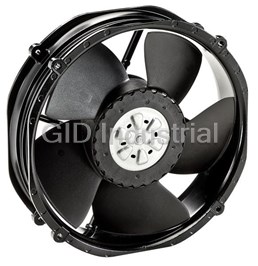
DC Fan Axial Ball Bearing 24V 16V to 36V 552.9CFM 66dB Low Noise/PWM 2214F/2TDHHO
DC Fan Axial Sintec-Sleeve Bearing 12V 10V to 14V 1.9CFM 15dB 25 X 25 X 8mm Low Power Consumption 25...
DC Fan Axial Sintec-Sleeve Bearing 5V 4.5V to 5.5V 2.7CFM 23dB 25 X 25 X 8mm Low Power Consumption 2...
DC Fan Axial Sintec-Sleeve Bearing 5V 4.5V to 5.5V 1.2CFM 5dB 25 X 25 X 8mm Low Power Consumption 25...
DC Fan Axial Sintec-Sleeve Bearing 5V 4.5V to 5.5V 1.9CFM 16dB 25 X 25 X 8mm Low Power Consumption 2...
DC Fan Axial Ball Bearing 12V 6V to 13.8V 140CFM 69dB 92 X 92 X 38mm 3212J/2H3


Request a Quote

The quote request has been received

Close

Facing challenges or have inquiries? Feel free to contact us!
Call Us +1-469-283-2440
What they say about us
FANTASTIC RESOURCE
One of our top priorities is maintaining our business with precision, and we are constantly looking for affiliates that can help us achieve our goal. With the aid of GID Industrial, our obsolete product management has never been more efficient. They have been a great resource to our company, and have quickly become a go-to supplier on our list!
Bucher Emhart Glass
EXCELLENT SERVICE
With our strict fundamentals and high expectations, we were surprised when we came across GID Industrial and their competitive pricing. When we approached them with our issue, they were incredibly confident in being able to provide us with a seamless solution at the best price for us. GID Industrial quickly understood our needs and provided us with excellent service, as well as fully tested product to ensure what we received would be the right fit for our company.
Fuji
HARD TO FIND A BETTER PROVIDER
Our company provides services to aid in the manufacture of technological products, such as semiconductors and flat panel displays, and often searching for distributors of obsolete product we require can waste time and money. Finding GID Industrial proved to be a great asset to our company, with cost effective solutions and superior knowledge on all of their materials, it’d be hard to find a better provider of obsolete or hard to find products.
Applied Materials
CONSISTENTLY DELIVERS QUALITY SOLUTIONS
Over the years, the equipment used in our company becomes discontinued, but they’re still of great use to us and our customers. Once these products are no longer available through the manufacturer, finding a reliable, quick supplier is a necessity, and luckily for us, GID Industrial has provided the most trustworthy, quality solutions to our obsolete component needs.
Nidec Vamco
TERRIFIC RESOURCE
This company has been a terrific help to us (I work for Trican Well Service) in sourcing the Micron Ram Memory we needed for our Siemens computers. Great service! And great pricing! I know when the product is shipping and when it will arrive, all the way through the ordering process.
Trican Well Service
GO TO SOURCE
When I can't find an obsolete part, I first call GID and they'll come up with my parts every time. Great customer service and follow up as well. Scott emails me from time to time to touch base and see if we're having trouble finding something.....which is often with our 25 yr old equipment.
ConAgra Foods