

 Manufacturers
ERNI ELECTRONICS 103850

Description
Connector Accessories Upper Shielded Cover For Daughter Cards 11 POS
103850
Part Number
103850
Price
Request Quote
Manufacturer
ERNI ELECTRONICS
Lead Time
Request Quote
Category
Connectors » Connector Accessories
Specifications
Manufacturer
ERNI Electronics
Manufacturers Part #
103850
Industry Aliases
103850
Sub-Category
Connector Accessories
Factory Pack Quantity
54
Datasheet

Extracted Text
2mm Hard Metric Connectors Acc. To IEC 61076-4-101 Updates of this catalog will be made available on Online Catalog the web: http://Connect.ERNI.com/ERmet.ssi 70 Catalog E 074482 08/06 Edition 4 www.erni.com ERmet 2.0mm Table Of Contents ERmet 2mm Hard Metric Connectors . . . . . . . . . . . . . . . . . . . . . . . . . . . . . . . . . . . . . . . . . . . . . . . . . . . . . . . . . . . . . . . . . . . . . .73 Product Overview . . . . . . . . . . . . . . . . . . . . . . . . . . . . . . . . . . . . . . . . . . . . . . . . . . . . . . . . . . . . . . . . . . . . . . . . . . . . . . . . . . . . . .74 Complementary Components . . . . . . . . . . . . . . . . . . . . . . . . . . . . . . . . . . . . . . . . . . . . . . . . . . . . . . . . . . . . . . . . . . . . . . . . . . . .78 Comparison Of 2.0 mm Connectors . . . . . . . . . . . . . . . . . . . . . . . . . . . . . . . . . . . . . . . . . . . . . . . . . . . . . . . . . . . . . . . . . . . . . . .79 Comparison Of 2.0 mm Connector Lines . . . . . . . . . . . . . . . . . . . . . . . . . . . . . . . . . . . . . . . . . . . . . . . . . . . . . . . . . . . . . . . . . . . .80 Application Notes . . . . . . . . . . . . . . . . . . . . . . . . . . . . . . . . . . . . . . . . . . . . . . . . . . . . . . . . . . . . . . . . . . . . . . . . . . . . . . . . . . . . . .81 Product Features . . . . . . . . . . . . . . . . . . . . . . . . . . . . . . . . . . . . . . . . . . . . . . . . . . . . . . . . . . . . . . . . . . . . . . . . . . . . . . . . . . . . . .82 Design Requirements For Printed Circuit Boards . . . . . . . . . . . . . . . . . . . . . . . . . . . . . . . . . . . . . . . . . . . . . . . . . . . . . . . . . . . . . .84 Alignment Tolerance . . . . . . . . . . . . . . . . . . . . . . . . . . . . . . . . . . . . . . . . . . . . . . . . . . . . . . . . . . . . . . . . . . . . . . . . . . . . . . . . . . .85 Midplane and Stacking Applications . . . . . . . . . . . . . . . . . . . . . . . . . . . . . . . . . . . . . . . . . . . . . . . . . . . . . . . . . . . . . . . . . . . . . . .85 Shroud Selection Information . . . . . . . . . . . . . . . . . . . . . . . . . . . . . . . . . . . . . . . . . . . . . . . . . . . . . . . . . . . . . . . . . . . . . . . . . . . . .86 Ordering Information . . . . . . . . . . . . . . . . . . . . . . . . . . . . . . . . . . . . . . . . . . . . . . . . . . . . . . . . . . . . . . . . . . . . . . . . . . . . . . . . . . .87 Mechanical Specifications And Performance . . . . . . . . . . . . . . . . . . . . . . . . . . . . . . . . . . . . . . . . . . . . . . . . . . . . . . . . . . . . . . . . .89 Electrical And Mechanical Characters For Power Modules . . . . . . . . . . . . . . . . . . . . . . . . . . . . . . . . . . . . . . . . . . . . . . . . . . . . . . .90 7-Row Electrical Performance . . . . . . . . . . . . . . . . . . . . . . . . . . . . . . . . . . . . . . . . . . . . . . . . . . . . . . . . . . . . . . . . . . . . . . . . . . . .93 High Frequency Characteristics . . . . . . . . . . . . . . . . . . . . . . . . . . . . . . . . . . . . . . . . . . . . . . . . . . . . . . . . . . . . . . . . . . . . . . . . . . .93 7-Row Electrical Performance . . . . . . . . . . . . . . . . . . . . . . . . . . . . . . . . . . . . . . . . . . . . . . . . . . . . . . . . . . . . . . . . . . . . . . . . . . . .94 10-Row Electrical Performance . . . . . . . . . . . . . . . . . . . . . . . . . . . . . . . . . . . . . . . . . . . . . . . . . . . . . . . . . . . . . . . . . . . . . . . . . . .95 High Frequency Characteristics . . . . . . . . . . . . . . . . . . . . . . . . . . . . . . . . . . . . . . . . . . . . . . . . . . . . . . . . . . . . . . . . . . . . . . . . . . .95 10-Row Electrical Performance . . . . . . . . . . . . . . . . . . . . . . . . . . . . . . . . . . . . . . . . . . . . . . . . . . . . . . . . . . . . . . . . . . . . . . . . . . .96 Approval Certificates, Performance Levels And Ordering Information . . . . . . . . . . . . . . . . . . . . . . . . . . . . . . . . . . . . . . . . . . . . . . .97 Right Angle Female Connectors Type A For Daughter Cards . . . . . . . . . . . . . . . . . . . . . . . . . . . . . . . . . . . . . . . . . . . . . . . . . . . . .98 Vertical Male Connectors Type A For Backplanes . . . . . . . . . . . . . . . . . . . . . . . . . . . . . . . . . . . . . . . . . . . . . . . . . . . . . . . . . . . . .100 Vertical Female Connectors Type A . . . . . . . . . . . . . . . . . . . . . . . . . . . . . . . . . . . . . . . . . . . . . . . . . . . . . . . . . . . . . . . . . . . . . . .105 Right Angle Female Connectors Type B For Daughter Cards . . . . . . . . . . . . . . . . . . . . . . . . . . . . . . . . . . . . . . . . . . . . . . . . . . . .109 Vertical Male Connectors Type B For Backplanes . . . . . . . . . . . . . . . . . . . . . . . . . . . . . . . . . . . . . . . . . . . . . . . . . . . . . . . . . . . . .112 Vertical Female Connectors Type B . . . . . . . . . . . . . . . . . . . . . . . . . . . . . . . . . . . . . . . . . . . . . . . . . . . . . . . . . . . . . . . . . . . . . . .118 Right Angle Female Connectors Type AB For Daughter Cards . . . . . . . . . . . . . . . . . . . . . . . . . . . . . . . . . . . . . . . . . . . . . . . . . . .123 Vertical Male Connectors Type AB For Backplanes . . . . . . . . . . . . . . . . . . . . . . . . . . . . . . . . . . . . . . . . . . . . . . . . . . . . . . . . . . .126 Right Angle Female Connectors Type C For Daughter Cards . . . . . . . . . . . . . . . . . . . . . . . . . . . . . . . . . . . . . . . . . . . . . . . . . . . .128 Vertical Male Connectors Type C For Backplanes . . . . . . . . . . . . . . . . . . . . . . . . . . . . . . . . . . . . . . . . . . . . . . . . . . . . . . . . . . . . .130 Vertical Female Connectors Type C . . . . . . . . . . . . . . . . . . . . . . . . . . . . . . . . . . . . . . . . . . . . . . . . . . . . . . . . . . . . . . . . . . . . . . .133 Right Angle Female Connectors Type D For Daughter Cards . . . . . . . . . . . . . . . . . . . . . . . . . . . . . . . . . . . . . . . . . . . . . . . . . . . .137 Vertical Male Connectors Type D For Backplanes . . . . . . . . . . . . . . . . . . . . . . . . . . . . . . . . . . . . . . . . . . . . . . . . . . . . . . . . . . . . .139 Vertical Female Connectors Type D . . . . . . . . . . . . . . . . . . . . . . . . . . . . . . . . . . . . . . . . . . . . . . . . . . . . . . . . . . . . . . . . . . . . . . .141 Right Angle Female Connectors Type E For Daughter Cards . . . . . . . . . . . . . . . . . . . . . . . . . . . . . . . . . . . . . . . . . . . . . . . . . . . .143 Vertical Male Connectors Type E For Backplanes . . . . . . . . . . . . . . . . . . . . . . . . . . . . . . . . . . . . . . . . . . . . . . . . . . . . . . . . . . . . .145 Vertical Female Connectors Type E . . . . . . . . . . . . . . . . . . . . . . . . . . . . . . . . . . . . . . . . . . . . . . . . . . . . . . . . . . . . . . . . . . . . . . .147 Right Angle Female Connectors Type DE For Daughter Cards . . . . . . . . . . . . . . . . . . . . . . . . . . . . . . . . . . . . . . . . . . . . . . . . . . .149 Vertical Male Connectors Type DE For Backplanes . . . . . . . . . . . . . . . . . . . . . . . . . . . . . . . . . . . . . . . . . . . . . . . . . . . . . . . . . . . .151 Right Angle Female Connectors Type F For Daughter Cards . . . . . . . . . . . . . . . . . . . . . . . . . . . . . . . . . . . . . . . . . . . . . . . . . . . .153 Vertical Male Connectors Type F For Backplanes . . . . . . . . . . . . . . . . . . . . . . . . . . . . . . . . . . . . . . . . . . . . . . . . . . . . . . . . . . . . .155 Vertical Female Connectors Type F . . . . . . . . . . . . . . . . . . . . . . . . . . . . . . . . . . . . . . . . . . . . . . . . . . . . . . . . . . . . . . . . . . . . . . . .157 Right Angle Female Connectors Type L For Daughter Cards . . . . . . . . . . . . . . . . . . . . . . . . . . . . . . . . . . . . . . . . . . . . . . . . . . . .159 Vertical Male Connectors Type L For Backplanes . . . . . . . . . . . . . . . . . . . . . . . . . . . . . . . . . . . . . . . . . . . . . . . . . . . . . . . . . . . . .161 Right Angle Female Connectors Type M For Daughter Cards . . . . . . . . . . . . . . . . . . . . . . . . . . . . . . . . . . . . . . . . . . . . . . . . . . . .163 Vertical Male Connectors Type M For Backplanes . . . . . . . . . . . . . . . . . . . . . . . . . . . . . . . . . . . . . . . . . . . . . . . . . . . . . . . . . . . .165 Right Angle Female Connectors Type N For Daughter Cards . . . . . . . . . . . . . . . . . . . . . . . . . . . . . . . . . . . . . . . . . . . . . . . . . . . .167 Vertical Male Connectors Type N For Backplanes . . . . . . . . . . . . . . . . . . . . . . . . . . . . . . . . . . . . . . . . . . . . . . . . . . . . . . . . . . . . .169 Shrouds Type A For Backplanes . . . . . . . . . . . . . . . . . . . . . . . . . . . . . . . . . . . . . . . . . . . . . . . . . . . . . . . . . . . . . . . . . . . . . . . . .171 Shrouds Type B For Backplanes . . . . . . . . . . . . . . . . . . . . . . . . . . . . . . . . . . . . . . . . . . . . . . . . . . . . . . . . . . . . . . . . . . . . . . . . .174 Shrouds Type C For Backplanes . . . . . . . . . . . . . . . . . . . . . . . . . . . . . . . . . . . . . . . . . . . . . . . . . . . . . . . . . . . . . . . . . . . . . . . . .178 Catalog E 074482 08/06 Edition 4 www.erni.com 71 Table Of Contents Shrouds Type AB For Backplanes . . . . . . . . . . . . . . . . . . . . . . . . . . . . . . . . . . . . . . . . . . . . . . . . . . . . . . . . . . . . . . . . . . . . . . . .180 Shrouds Type D For Backplanes . . . . . . . . . . . . . . . . . . . . . . . . . . . . . . . . . . . . . . . . . . . . . . . . . . . . . . . . . . . . . . . . . . . . . . . . .184 Shrouds Type E For Backplanes . . . . . . . . . . . . . . . . . . . . . . . . . . . . . . . . . . . . . . . . . . . . . . . . . . . . . . . . . . . . . . . . . . . . . . . . . .186 Shrouds Type F For Backplanes . . . . . . . . . . . . . . . . . . . . . . . . . . . . . . . . . . . . . . . . . . . . . . . . . . . . . . . . . . . . . . . . . . . . . . . . . .188 Right Angle Female Monoblock Modules . . . . . . . . . . . . . . . . . . . . . . . . . . . . . . . . . . . . . . . . . . . . . . . . . . . . . . . . . . . . . . . . . . .190 Vertical Male Monoblock Modules . . . . . . . . . . . . . . . . . . . . . . . . . . . . . . . . . . . . . . . . . . . . . . . . . . . . . . . . . . . . . . . . . . . . . . . .192 Right Angle Male Power Modules For Daughter Cards . . . . . . . . . . . . . . . . . . . . . . . . . . . . . . . . . . . . . . . . . . . . . . . . . . . . . . . . .194 Vertical Female Power Modules For Backplanes . . . . . . . . . . . . . . . . . . . . . . . . . . . . . . . . . . . . . . . . . . . . . . . . . . . . . . . . . . . . .196 Dust Covers For Type A, B, AB, D, E and DE . . . . . . . . . . . . . . . . . . . . . . . . . . . . . . . . . . . . . . . . . . . . . . . . . . . . . . . . . . . . . . . .198 Coding Keys . . . . . . . . . . . . . . . . . . . . . . . . . . . . . . . . . . . . . . . . . . . . . . . . . . . . . . . . . . . . . . . . . . . . . . . . . . . . . . . . . . . . . . . .200 Guide Pin For ERmet 10 Row Type D . . . . . . . . . . . . . . . . . . . . . . . . . . . . . . . . . . . . . . . . . . . . . . . . . . . . . . . . . . . . . . . . . . . . . .201 Special Contacts For Type L, M And N . . . . . . . . . . . . . . . . . . . . . . . . . . . . . . . . . . . . . . . . . . . . . . . . . . . . . . . . . . . . . . . . . . . . .202 Modular press-fit tools for male and female connectors . . . . . . . . . . . . . . . . . . . . . . . . . . . . . . . . . . . . . . . . . . . . . . . . . . . . . . . .203 Press-In-Tools For The Female Connectors . . . . . . . . . . . . . . . . . . . . . . . . . . . . . . . . . . . . . . . . . . . . . . . . . . . . . . . . . . . . . . . . .204 Press-In-Tools For The Male Connectors . . . . . . . . . . . . . . . . . . . . . . . . . . . . . . . . . . . . . . . . . . . . . . . . . . . . . . . . . . . . . . . . . . .205 Toolholder . . . . . . . . . . . . . . . . . . . . . . . . . . . . . . . . . . . . . . . . . . . . . . . . . . . . . . . . . . . . . . . . . . . . . . . . . . . . . . . . . . . . . . . . . .205 3U CompactPCI® Daughter Card Layout . . . . . . . . . . . . . . . . . . . . . . . . . . . . . . . . . . . . . . . . . . . . . . . . . . . . . . . . . . . . . . . . . .206 3U CompactPCI® Backplane Layout . . . . . . . . . . . . . . . . . . . . . . . . . . . . . . . . . . . . . . . . . . . . . . . . . . . . . . . . . . . . . . . . . . . . .207 6U CompactPCI® Daughter Card Layout . . . . . . . . . . . . . . . . . . . . . . . . . . . . . . . . . . . . . . . . . . . . . . . . . . . . . . . . . . . . . . . . . .208 6U CompactPCI® Backplane Layout . . . . . . . . . . . . . . . . . . . . . . . . . . . . . . . . . . . . . . . . . . . . . . . . . . . . . . . . . . . . . . . . . . . . . .209 9U 10-Row 2mm Daughter Card Layout . . . . . . . . . . . . . . . . . . . . . . . . . . . . . . . . . . . . . . . . . . . . . . . . . . . . . . . . . . . . . . . . . . .210 9U 10-Row 2mm Backplane Layout . . . . . . . . . . . . . . . . . . . . . . . . . . . . . . . . . . . . . . . . . . . . . . . . . . . . . . . . . . . . . . . . . . . . . .211 IEEE 1301 Daughter Cards for IEC 61076-4-101 2mm HM Connectors . . . . . . . . . . . . . . . . . . . . . . . . . . . . . . . . . . . . . . . . . . .212 IEEE 1301 Backplane Layouts For IEC 61076-4-101 2mm HM Connectors . . . . . . . . . . . . . . . . . . . . . . . . . . . . . . . . . . . . . . . .213 VME64 Extensions Daughter Card . . . . . . . . . . . . . . . . . . . . . . . . . . . . . . . . . . . . . . . . . . . . . . . . . . . . . . . . . . . . . . . . . . . . . . . .214 VME64 Extensions Backplane . . . . . . . . . . . . . . . . . . . . . . . . . . . . . . . . . . . . . . . . . . . . . . . . . . . . . . . . . . . . . . . . . . . . . . . . . . .215 64 Bit CompactPCI® System Slot Pin Assignments . . . . . . . . . . . . . . . . . . . . . . . . . . . . . . . . . . . . . . . . . . . . . . . . . . . . . . . . . . .216 64 Bit CompactPCI® Peripheral Slot Pin Assignments . . . . . . . . . . . . . . . . . . . . . . . . . . . . . . . . . . . . . . . . . . . . . . . . . . . . . . . . .217 32 Bit CompactPCI® System Slot Pin Assignments . . . . . . . . . . . . . . . . . . . . . . . . . . . . . . . . . . . . . . . . . . . . . . . . . . . . . . . . . .218 32 Bit CompactPCI® Peripheral Slot Pin Assignments . . . . . . . . . . . . . . . . . . . . . . . . . . . . . . . . . . . . . . . . . . . . . . . . . . . . . . . .219 cPCI Computer Telephony P4 Pin Assignments . . . . . . . . . . . . . . . . . . . . . . . . . . . . . . . . . . . . . . . . . . . . . . . . . . . . . . . . . . . . . .220 cPCI Computer Telephony Safety Classifications for J4/P4 . . . . . . . . . . . . . . . . . . . . . . . . . . . . . . . . . . . . . . . . . . . . . . . . . . . . .221 cPCI Computer Telephony P5 Pin Assignments . . . . . . . . . . . . . . . . . . . . . . . . . . . . . . . . . . . . . . . . . . . . . . . . . . . . . . . . . . . . . .222 cPCI Computer Telephony Safety Classifications for J5/P5 . . . . . . . . . . . . . . . . . . . . . . . . . . . . . . . . . . . . . . . . . . . . . . . . . . . . .223 PXI Generic Peripheral Slot Pinout . . . . . . . . . . . . . . . . . . . . . . . . . . . . . . . . . . . . . . . . . . . . . . . . . . . . . . . . . . . . . . . . . . . . . . . .224 VME64x on CompactPCI® J4/P4 and J5/P5 Pin Assignments . . . . . . . . . . . . . . . . . . . . . . . . . . . . . . . . . . . . . . . . . . . . . . . . . .227 PMC Mezzanine Card I/O Pin Assignments . . . . . . . . . . . . . . . . . . . . . . . . . . . . . . . . . . . . . . . . . . . . . . . . . . . . . . . . . . . . . . . .228 Single PMC’s I/O Signal Mapping to CompactPCI® 3U J2 Connector . . . . . . . . . . . . . . . . . . . . . . . . . . . . . . . . . . . . . . . . . . . . .228 PMC Mezzanine Card I/O Pin Assignments . . . . . . . . . . . . . . . . . . . . . . . . . . . . . . . . . . . . . . . . . . . . . . . . . . . . . . . . . . . . . . . . .229 IP Mezzanine Module I/O Pin Assignments . . . . . . . . . . . . . . . . . . . . . . . . . . . . . . . . . . . . . . . . . . . . . . . . . . . . . . . . . . . . . . . . .230 Bellcore Lubrication . . . . . . . . . . . . . . . . . . . . . . . . . . . . . . . . . . . . . . . . . . . . . . . . . . . . . . . . . . . . . . . . . . . . . . . . . . . . . . . . . . .232 Glossary Of Terminology . . . . . . . . . . . . . . . . . . . . . . . . . . . . . . . . . . . . . . . . . . . . . . . . . . . . . . . . . . . . . . . . . . . . . . . . . . . . . . .233 ERNI Customer Request Form . . . . . . . . . . . . . . . . . . . . . . . . . . . . . . . . . . . . . . . . . . . . . . . . . . . . . . . . . . . . . . . . . . . . . . . . . . .236 Applications . . . . . . . . . . . . . . . . . . . . . . . . . . . . . . . . . . . . . . . . . . . . . . . . . . . . . . . . . . . . . . . . . . . . . . . . . . . . . . . . . . . . . . . . .239 Right Angle Male Connectors Type A for Daughter Cards . . . . . . . . . . . . . . . . . . . . . . . . . . . . . . . . . . . . . . . . . . . . . . . . . . . . . .240 Right Angle Male Connectors Type A for Daughter Cards Ordering Information . . . . . . . . . . . . . . . . . . . . . . . . . . . . . . . . . . . . . .241 Right Angle Male Connectors Type B for Daughter Cards . . . . . . . . . . . . . . . . . . . . . . . . . . . . . . . . . . . . . . . . . . . . . . . . . . . . . .242 Right Angle Male Connectors Type b for Daughter Cards Ordering Information . . . . . . . . . . . . . . . . . . . . . . . . . . . . . . . . . . . . . .243 Right Angle Male Connectors Type b for Daughter Cards Other Lenghts Ordering Information . . . . . . . . . . . . . . . . . . . . . . . . . .244 Right Angle Male Connectors Type C for Daughter Cards . . . . . . . . . . . . . . . . . . . . . . . . . . . . . . . . . . . . . . . . . . . . . . . . . . . . . .246 Right Angle Male Connectors Type C for Daughter Cards Ordering Information . . . . . . . . . . . . . . . . . . . . . . . . . . . . . . . . . . . . . .247 72 Catalog E 074482 08/06 Edition 4 www.erni.com ERmet 2.0mm ERmet 2mm Hard Metric Connectors Introduction Features The ERmet 2mm H.M. connector line from ERNI offers • Modular connectors with 2.0 mm signal contact pitch for unparalleled performance and flexibility for today’s high per- backplanes and daughter cards. formance circuit designs. Since its introduction • High density board to backplane connector system. in 1993, this product line has expanded and now offers • Up to 8 signal rows plus two shield rows for optimum per- almost every module configuration possible in a board formance. to backplane interconnect system. Standard and reverse • Three levels of sequential mating for front or rear hot swap configurations are available including shielded vertical applications. 1.5 mm increments. females, stacking designs, stamped power connectors and • 15 standard contacts available for any pin loading require- cable systems. This connector system has now become the ment. standard for board to backplane • Complete line of complementary accessories to include applications. stamped power connectors, color coded coding keys, The ERmet 2mm H.M. connector system has achieved latching shrouds, cable connectors, ground return shields, widespread acceptance and popularity as the interconnect high frequency, and high power contacts. system chosen for CompactPCI. It is also widely used by • Superior female connector contact design provides a uni- OEMs serving the telecommunications and networking form signal path. industry segments. It has achieved • Comply to the international standard IEC 61076-4-101. this unparalleled acceptance due to its high frequency per- • For networking, telecommunications, high performance formance, its wide selection of modular components and its computing and other demanding applications. cost-benefit ratio. This connector is supported by one of the industry’s most comprehensive international connector standards, IEC 61076-4-101. Whether you are developing a new backplane, a high performance CPU or I/O card or integrating a sophisticated hybrid system, ERNI has anticipated your needs. The ERNI team stands ready to partner with you to develop the most efficient solution to your design challenge. Catalog E 074482 08/06 Edition 4 www.erni.com 73 Product Overview ERmet 2mm H.M. connectors are a versatile, cost-effective cable latches. board-to-backplane solution for today’s high performance, For circuit design versatility, the connectors are offered with high density applications. a selection of contacts including signal, The ERmet 2mm H.M. line consists of 26 different module high power, high frequency and coaxial. They are available types including matching shrouds for midplane, stacking in 50mm, 44 mm, 38 mm, and 25mm modules for end-to- and cable applications, cable connectors, power modules, end stacking without contact loss. The dual beam female upper and lower ground return shields, coding keys and contact design provides equalized signal path lengths which Type A Connector Type B Connector Type C Connector • 110 signal contacts. • 125, 110 and 95 signal contacts. • 55 signal contacts. • 44 shield contacts. • 50 shield contacts. • 22 shield contacts. • 50 mm long including the • 50 mm, 44 mm and 38 mm long • 25 mm long. multifunction area for coding keys. without the multifunction area. • For end positions only. • Integral pre-alignment guide and • 3 contact lengths for sequential • Pre-alignment guide pins. polarizing pins. mating. • Optional locating pegs for printed • Optional locating pegs for printed circuit board (PCB) mounting. circuit board (PCB) mounting. • 3 contact lengths for sequential • 3 contact lengths for sequential mating. mating. Type D Connector Type E Connector Type F Connector • 176 signal contacts. • 200 signal contacts. • 88 signal contacts. • 44 shield contacts. • 50 shield contacts. • 22 shield contacts. • 50 mm long including the • 50 mm long without the • 25 mm long. multifunction area for coding keys. multifunction area. • For end positions only • Integral pre-alignment guide and • 3 contact lengths for sequential • Pre-alignment guide pins. polarizing pins. mating. • Optional locating pegs for printed • Optional locating pegs for printed circuit board (PCB) mounting. circuit board (PCB) mounting. • 3 contact lengths for sequential • Positions for optional early mate mating. ground pin. • 3 contact lengths for sequential mating. 74 Catalog E 074482 08/06 Edition 4 www.erni.com ERmet 2.0mm Product Overview Type A Ground Return Shield Type B Ground Return Shield Type C Ground Return Shield • Upper and lower shields for • Upper and lower shields for the Type • Upper and lower shields for Type A connectors. B female connectors. Type C and M connectors. • Upper shield available integrated • Upper shield available integrated • Upper shield available integrated with female connector or as with female connector or as with female connector or as sepa- separate component. separate component. rate component. Type D Ground Return Shield Type E Ground Return Shield Type F Ground Return Shield • Upper and lower shields for • Upper and lower shields for the Type • Upper and lower shields for Type D connectors. E female connectors. Type F connectors. • Upper shield available integrated • Upper shield available integrated • Upper shield available integrated with female connector or as with female connector or as with female connector or as sepa- separate component. separate component. rate component. Type L Connector Type M Connector Type N Connector • 6 special contact cavities. • 3 special contact cavities. • 3 special contact cavities. • 50 mm long. • 55 signal contacts. • 25 mm long. • Multifunction area for coding keys. • 50 mm long. • For end positions only • Integral pre-alignment guide and • Multifunction area for coding keys. • Pre-alignment guide pins. polarizing pins. • Integral pre-alignment guide and • Optional locating pegs for printed • Optional locating pegs for printed polarizing pins. circuit board (PCB) mounting. circuit board (PCB) mounting. • Optional locating pegs for printed circuit board (PCB) mounting. Catalog E 074482 08/06 Edition 4 www.erni.com 75 Product Overview Type A Vertical Female Connector Type B Vertical Female Connector Type C Vertical Female Connector • 110 signal contacts. • 125, 110 and 95 signal contacts. • 55 signal contacts. • 44 shield contacts. • 50, 44 and 38 shield contacts. • 22 shield contacts. • 50 mm long including the multifunc- • 50 mm, 44 mm and 38 mm long • 25 mm long. tion area for coding keys. without a multifunction area. • For end positions only • Pre-alignment guide and integral • Optional shields. • Pre-alignment guide pins. polarizing pins. • Extended terminals and spacers • Optional locating pegs for printed • Optional shields. available. circuit board (PCB) mounting. • Extended terminals and spacers • Optional shields. available. • Extended terminals and spacers available. Type AB25 Right Angle Female Type AB22 Right Angle Female Type AB19 Right Angle Female • 125 signal contacts. • 110 signal contacts. • 95 signal contacts. • 44 shield contacts. • 40 shield contacts. • 32 shield contacts. • 50 mm long. • 44 mm long. • 38 mm long. • Integral prealignment guide and • Integral prealignment guide and • Integral prealignment guide and polarizing pins. polarizing pins. polarizing pins. • AB compatible males also available. • AB compatible males also available. • AB compatible males also available. Connector Coding System Type DE Right Angle Female • Up to 70 unique male and female coding keys. • 200 signal contacts. • 50 shield contacts. • For use in the multifunction center of the Type A, D, L and M male or • 50 mm long. female connectors. • Integral prealignment guide and • Low cost, industry standard design. polarizing pins. • Easy snap-in installation – no epoxy adhesive required. • DE compatible males also available. • Bright colors for quick visual identification conform to industry standard. • Crush resistant construction, exceeds IEC requirements. 76 Catalog E 074482 08/06 Edition 4 www.erni.com ERmet 2.0mm Product Overview Type D Vertical Female Connector Type E Vertical Female Connector Type F Vertical Female Connector • 176 signal contacts. • 200 signal contacts. • 88 signal contacts. • 44 shield contacts. • 50 shield contacts. • 22 shield contacts. • 50 mm long including the multifunc- • 50 mm long without a multifunction • 25 mm long. tion area for coding keys. area. • For end positions only • Pre-alignment guide and integral • Optional shields. • Pre-alignment guide pins. polarizing pins. • Optional shields. • Optional shields. Catalog E 074482 08/06 Edition 4 www.erni.com 77 Complementary Components Type A Shroud Type B Shroud Type C Shroud • 4 heights for printed circuit boards • 4 heights for printed circuit boards • 4 heights for printed circuit boards (PCBs) 1.6 to 6.0 mm thick. (PCBs) 1.6 to 6.0 mm thick. (PCBs) 1.6 to 6.0 mm thick. • 50 mm and 38 mm long. • 50 mm, 44 mm and 38 mm long. • 25 mm long. • Multifunction area for coding keys. • For end positions only. Type AB 19 & AB 25 Shroud Type AB 22 Shroud Optional Latch Arm • 38 mm and 50 mm respectively. • 44 mm long. • Can be added to standard ERmet • Integral pre-alignment and guide • Integral pre-alignment and guide shroud body. pins. pins. • Spring action latch. • 4 heights for printed circuit boards • 4 heights for printed circuit boards • Easy installation, no tools required. (PCBs) 1.6 to 6.0 mm thick. (PCBs) 1.6 to 6.0 mm thick. Cable System Male & Female Power Module • Compatible with ERmet latching • Closed entry female connector for Monoblock Modules shrouds. backplane. • Male and Female monoblock mod- • 1 x 7 or 1 x 5 stackable housings • 3 pin levels for sequential mating. ules. can be joined together. • 8 ampere, per contact. • Optional integrated coding keys for • Maintains “z” and “f” row shield path. • Pressfit, flat rock assembly. 3.3V, 5.0V or Telecom applications. • High frequency contact design. • Multifunction area for coding keys. • Molded strain relief. • Available in a variety of configura- tions 94 or 100 mm long. 78 Catalog E 074482 08/06 Edition 4 www.erni.com ERmet 2.0mm A = 17.80 mm B = 23.80 mm A = 15.80 mm B = 21.80 mm A = 14.8 – 15.4 mm B = 20.8 – 21.4 mm Comparison Of 2.0 mm Connectors A 2.0 mm Connector For CompactPCI Needs To Be Different. Here’s Why. When you’re choosing a 2.0 mm connector for your pro- duct, it pays to give your choice a little extra thought. Just knowing a connector is a 2.0 mm connector is not enough – there are really three distinctly separate and non-intermateable connector lines. They are the Futurebus style, the HDM style and the Hard Metric style, such as the ERmet 2mm H.M. from ERNI for CompactPCI architecture. All three connector systems use a 2.0 mm grid and are offered in modular formats, but there the similarity ends. Each line has different printed circuit board hole sizes, contact sizes, shield configurations, keying methods and electrical character- istics. In short, there are very few similarities beyond the 2.0 mm grids they share. All three 2.0 mm connector designs consist of multi-row pin headers on the backplane, right angle female connectors on the daughter card and a 2.0 mm grid spacing. One immediate difference is in terminal area design. The HDM style has exposed terminals on the right angle daughter card female connector, while the Futurebus and Hard Metric designs have encapsulated terminals. The 5+2 row Hard Metric backplane connector is 3.0 mm more narrow than the 5+2 row Futurebus connector. The 7 (5+2) row Hard Metric connector is more nar- row even than the 6 row HDM connector. The Hard Metric design preserves more space on the backplane for compo- nents that must be placed between the connectors. The mating distances also differ between the three product lines. Mating distance is measured from the rear edge of the daughter card to the front surface of the backplane when the daughter card is fully seated. The Futurebus mating distance is 10 mm, while the mating distance for both Hard Metric and HDM is 12.5 mm. The 12.5 mm measurement is important because it matches the mating distance of the established DIN 41612 connectors and the 2.5 mm IEC 61076-4-100 connec- tor. Matching mating distances allows industries that use Euro- card packaging (IEC 273 or IEEE 1101 or 1101.10) to build systems that combine the popular 96 pin DIN connectors and the newer Hard Metric and HDM connectors. This supports legacy architectures while allowing the addition of new features that require the greater signal density of 2.0 mm connectors. The VME64 Extensions committee chose the Hard Metric con- nector system for the P0/J0 connector because of this advan- tage. *Trademark of Teradyne Corporation ERmet 2mm H.M. Connectors Catalog E 074482 08/06 Edition 4 www.erni.com 79 C =12.50 mm D =14.00 mm C =10.00 mm D = 17.00 mm C =12.50 mm D =15.00 mm Comparison Of 2.0 mm Connector Lines Connector Lines ERNI TM Design Criteria HDM Futurebus Hard Metric 5+2/8+2 General Specification Proprietary IEC 1076-4-104 IEC 61076-4-101 Number of Rows (Signal and Ground) 6* 5+2 5+2 /8+2 Total Contacts Per Linear Inch 76 88 88/127 Number of Standard Modules 3 7 6/15 Width of Male Housing 15.8 mm 17.8 mm 15.4 mm – 2 1.4 mm Distance from Daughter Card Edge to Row A 2 .50 mm 7.00 mm 1.50 mm Mated Distance from Backplane Front to Row A 15.0 mm 17.0 mm 14.0 mm Signal Mating Levels / Step Distance 3 levels, 0.50 mm each 5 levels, 0.75 mm each 3 levels 1.50 mm each + EMI Shielding Yes Yes Yes +++ + Extended Guidance Features See footnote Add-On Module Integrated +++ Coding Locations See footnote Integrated Integrated Coding Combinations Per Location 83 70 Reverse Connector Configuration Yes Yes Yes Vertical Male Standard Connector Configuration + + Yes Yes Yes Vertical Female Power Contact Modules Yes Yes Yes Coaxial Contact Modules Yes Yes Yes Maximum Contact Resistance of Mated Pair 40 mΩ 50 mΩ 2 0 mΩ Propagation Delay (max.)++ 235 ps 210 ps 135 ps/190 ps PCB Plated Hole Size 0.70 mm 0.70 mm 0.60 mm Daughter Card Yes Yes Yes Press-Fit Termination Backplane Yes Yes Yes * Shield Pins Implemented Through Signal Pins + Not Defined in (IEC) Specification ++ Published Industry Test Results +++ Integrated in Header and add-on module for female 80 Catalog E 074482 08/06 Edition 4 www.erni.com ERmet 2.0mm Application Notes The ERmet 2mm H.M. connector system now consists of Specific contact loading configurations have already been two basic signal module configurations. The original 5+2 defined for standard applications and special needs like live design and the newer 8+2 design for higher pin count insertion on CompactPCI. However, to specify a custom requirements. Both connector systems consist of a daugh- loading configuration, use the ERNI customer request forms ter card mounted, right angle female connector featuring located in the back of the catalog. A form is provided for the the high performance, low skew patented ERmet leaf con- 5+2 configuration and another form is available for the 8+2 tact design and a versatile vertical male header mounted on configuration. the backplane. Additionally, this arrangement is particularly effective for midplane application and makes sequential Features mating easy. • 3 step lengths in 1.5 mm increments ensure dependable ERNI can provide 15 standard pins in any row or position sequential mating. required for your design. This allows for three levels of • Both front and rear mating areas meet the same IEC per- sequential mating in both the front and rear of the back- formance level. plane, as well as two shorter terminal lengths for applica- • 15 pin lengths defined by IEC 61076-4-101. tions which don’t require rear feed through pins. • Long terminal contacts (R1, R2 and R3) require the use of For midplane and rear I/O applications, ERNI offers comple- rear shrouds. mentary 2.0 mm shrouds, vertical female connectors, cable connectors and latch accessories which are used in con- junction with the long terminal lengths (R1, R2 and R3). Backplane Connector Daughter Card Connector Two outer rows for shielding purposes Upper Shield F E D C Centerline Centerline B Row B Row B A Printed Circuit Board (PCB) Z Insulator Two-sided contact Press-fit zone thickness springs 3 mm Lower Shield Press-fit zone Backplane Upper Shield Two-sided contact springs 3 mm Insulator thickness I H G F E D Printed Circuit Board (PCB) C Centerline Centerline C B L Row B Row B A Z Press-fit zone Two-sided contact springs Lower Shield Press-fit zone Catalog E 074482 08/06 Edition 4 www.erni.com 81 Product Features AB Alignment Option (features) The IEC 61076-4-101 connector standard only provides for connector Types A, B, C, D, E, F, L, M and N. Many customers require a connector with the density of a Type B (25 columns) and with the pre-alignment guide pins of the Type A, D, L and M connectors. This became a particular issue within the CompactPCI computer architecture for rear plug in applications where only B connectors were being used. The problem is that if a plug in card only utilizes Type B connectors, the cards will not have adequate vertical alignment even in the most carefully constructed subrack. The result can be pin stubbing and ultimately serious dam- age to both the backplane connectors and the female con- nectors on the daughter cards. For our customers who need a solution to this situation or who need the additional 15 pins that a Type B connector provides, but who also need the vertical alignment that the pre-alignment guide pins afford, ERNI has developed the Type AB connector. This new AB design, which does not allow for coding keys, is now required for rP3 and rP5 shrouds by the current draft PICMG Core specification (draft 3.0). Coding Keys CompactPCI® supports both con- ventional 5.0 V logic and 3.3 V logic. To prevent damage to the system resulting from incorrect insertion of cards with differing logic, coding keys are snapped into the multi- functional area of the male and female connector. This is done with the use of a plastic tool after the connector has been pressed in. The unique, bright color of the coding pairs allows for quick and easy visual identifica- tion and differentiation. For the 5.0 V logic, CompactPCI® use brilliant blue coding keys, 3.3 V logic use cadmium yellow and Telecom applications use strawberry red. The IEC 61076-4-101 standard defines a unique configuration and color for 70 different coding keys. The ERNI design has special integral supports that exceed the IEC requirements. 82 Catalog E 074482 08/06 Edition 4 www.erni.com ERmet 2.0mm 2.5 mm minimum Male Contact Range wipe length The ERmet 2mm H.M. Connector System has one of the e longest wipe areas of any connector system as defined in d e IEC 61076-4-101. This ensures reliable contact mating c d 2.5 b even under adverse mating conditions. Features include: c a b • 2.5 mm minimum wipe length for all three contact a lengths. • The required wipe length for rear applications may be 16.5 14 achieved by selecting the proper rear shroud height for the backplane thickness. 0.2 max. • IEC standardization completely defines tip blade and con- tact geometry, thus ensuring intermatability. zabcdef zabcdef Relation To IEEE 1101.10 And IEC 297.3 The ERmet 2mm H.M. Connector System has been chosen avoid any interference with the interboard separation plane. by the PICMG for the CompactPCI bus architecture and the This ensures that the daughter card and shield assembly VITA Standards Organization for the VME64 Extensions, will not snag or interfere with high components in the adja- PO/JO connector. Both of these applications require this cent slot during installation or removal. connector to be used in 0.8” wide slots in accordance with Interboard Separation Plane IEC 297.3 and IEEE 1101.10 mechanical chassis require- 6.85 8.63 ments. This chassis system defines the daughter card loca- tion within the card slot, relative to the interboard separation 20.32 planes. When the ERmet Connector System is used within 15.4 B Row Centerline B Row Centerline such a chassis system, the dimensions shown in the draw- 4.07 Interboard Separation Plane ing will be observed. ERNI has designed the lower shield to 1.33 14.0 Male Contact Selection Options The ERmet 2mm H.M. Connector System offers 15 standard contact lengths that utilize the proven pressfit assembly technique. Within the 15 contact lengths are 3 mating levels, achievable on both the plug-in and rear I/O side. Note you always keep 1.5 mm spacing between levels, for enhanced sequential mating. On the plug-in side, the 3 contact levels are: 8.2 mm, 9.7 mm and 11.2 mm. On the rear I/O side there are 5 pressfit terminal length options: P1, P2, R1, R2, and R3. The P1 and P2 terminal lengths are for standard backplane applications with terminal lengths of 3.7 mm and 4.5 mm respectively. The R1, R2 and R3 terminal lengths are for rear I/O applications with lengths of 13.0 mm, 14.5 mm and 16.0 mm respectively. The optimum terminal length is determined by the printed circuit board thickness, rear shroud height and the desired mating level. For contact plating information, refer to the Mechanical Specifications. To specify custom loading configurations, use the ERNI Customer Request Form. Catalog E 074482 08/06 Edition 4 www.erni.com 83 Compliant Pressfit Pins The ERmet 2mm H.M. connector line utilizes the proven pressfit assembly method. This design was chosen because it is an efficient assembly method that offers a number of benefits over soldering including higher reliability, easier inspection and repairability, and easier installation. In addition, the pressfit method avoids exposing the high layer count printed circuit boards (PCBs) to the additional thermal stress of soldering. Design Requirements For Printed Circuit Boards Plated Through-hole For Pressfitting Signal Contacts, Power Contacts And Shielding Contacts All ERmet 5+2 row and 8+2 row signal contacts are pressfit. Bohrungsdurchmesser 0,02 0,7 des Loches In addition, the bladed ERmet power connectors are also Diameter of drilled hole Durchmesser des 0,6 0,05 metallisierten Loches pressfit and share the same board plated hole requirements Diameter of finished plated-through hole min. 0,05 Restringbreite as the male and female signal connectors. The ERmet 2mm Restring width H.M. Connectors have been used successfully with reflowed tin-lead, plated tin-lead, immersion tin, organic coatings over bare copper and immersion gold hole plating regimes. The hole recommendations and press in force information max. 15 µm 1) Sn / SnPb shown in this catalog are for reflowed tin-lead and plated tin- min. 25 µm Cu lead. Additional test data for other hole plating regimes are available through customer service. Plated Through-hole For Pressfitting High-current Contacts (Special Contacts For Modules L, M And N) The ERmet Type L, M and N connectors have provisions Bohrungsdurchmesser 3,1 -0,03 des Loches for high frequency coaxial and high current circular con- Diameter of drilled hole Durchmesser des +0,04 3 -0,06 metallisiertes Loches tacts. These contacts have a variety of different plated Diameter of finished plated-through hole Restringbreite min. 0.8 through-hole requirements. For these, please consult ERNI restring width Customer Service. However, ERNI does offer both 20 Amp and 40 Amp high power pressfit contacts for the L, M, and N connectors, min. 25 µm Cu max. 15 µ 1) m which have the specific plated through-hole requirements Sn/SnPb shown to the right. Bohrungsdurchmesser 3,6 -0,03 des Loches Diameter of drilled hole Durchmesser des +0,04 3,5 -0,06 metallisierten Loches Diameter of finished plated-through hole min. 0.8 Restringbreite Restring width min. 25 µm Cu max. 15 µm 1) Sn/SnPb Maximum Circuit Density The dense ERmet 2.0 mm grid spacing utilizes a 0.6 mm plated through via. This via diameter, together with an appropriate plated annular ring, leaves a 1.0 mm minimum 2.0 0.2 (.008") space between adjacent annular rings for trace routing. This space allows for either two equally spaced conductor traces of 0.2 mm (.008") wide or three equally spaced 2 traces between pads conductors 0.14 mm (.006") wide, as shown in the drawing 2.0 to the right. This layout can be used to bus two or three rows of the connector on each layer respectively. Many 2.0 0.14 (.006") designers bus each row on a separate layer with a ground or power layer between for best signal integrity. 3 traces between pads 84 Catalog E 074482 08/06 Edition 4 www.erni.com ERmet 2.0mm Alignment Tolerance Allowed Misalignment Allowed Angular Inclination The pre-alignment pins ensure accurate alignment, elimi- nating the possibility of pin stubbing on the female insulator. When modules with the pre-alignment feature are used, the following mating tolerances can be accommodated: • Up to 2.0 mm of vertical or horizontal misalignment. • Up to 2 degrees of vertical or horizontal angular inclina- tion. Midplane and Stacking Applications Shroud Male Header Right Angle Right Angle Midplane – inline Female Female The most common configuration for mid plane applications is to have a rear shroud over long terminals. The rear shroud is oriented so that the shroud's "a" row lines up with the "a" row of the male connector on the front side of the backplane. In this configuration, the card guides in the front of the backplane line up exactly with those behind the backplane. Shroud Male Header Midplane – out of line Right Angle Female This less common configuration has the "a" row of the shroud aligned with the "e" row of the male connector on the front side of the backplane. In this configuration, the card that plugs into the rear side has the same appearance Right Angle as the board that plugs into the front side of the backplane. Female This usually requires a more complex card guide arrange- ment than the inline configuration. Parallel stacking This configuration has a vertical female connector on a Shroud Male Header mezzanine board mating into a rear shroud on the rear of a Right Angle Female backplane. This is a very popular method often used to connect two or more slots with a PCB which is parallel to Vertical the backplane. This is a common solution for switched fab- Female rics such as Raceway or for modular dedicated bused lines such as a special processor to board memory bus. The ERmet vertical female is also available with long tails to allow two levels of stacking. The ERNI vertical female has shields so all male pins can be contacted. Vertical females with long terminals are available for additional levels of stacking. Cable Connector Shroud Male Header Cable I/O All ERmet rear shrouds can be fitted with optional latch arms. This can be done during backplane assembly or later by the end customer. The latch arms allow the ERmet 2mm cable connector to be retained by the shroud. The ERmet 2mm cable system also mates with the "z" and "f" shield rows. This cable system is a very flexible method for taking Shroud Latch high speed signals from one backplane to elsewhere in a system or even to an adjacent backplane. Catalog E 074482 08/06 Edition 4 www.erni.com 85 3.0 Backplane Level 2 10.5 Level 1 Shroud Selection Information _ _ _ _ _ _ _ _ _ _ _ _ _ _ _ _ _ _ _ _ _ _ _ _ _ _ _ _ _ _ _ _ _ _ _ _ _ _ _ _ _ 8.5 _ _ _ _ _ _ _ _ _ _ _ _ _ _ _ _ _ _ _ _ _ _ _ _ _ _ _ _ _ _ _ _ _ _ _ _ _ _ _ _ _ After the backplane has been designed and its final overall _ _ _ _ _ _ _ _ _ _ _ _ _ _ _ _ _ _ _ _ _ _ _ _ _ _ _ _ _ _ _ _ _ _ _ _ _ _ _ _ _ _ _ _ _ _ _ _ _ _ _ _ _ _ _ _ _ _ _ _ _ _ _ _ _ _ _ _ _ _ _ _ _ _ _ _ _ _ _ _ _ _ thickness is determined, it is often challenging to select the _ _ _ _ _ _ _ _ _ _ _ _ _ _ _ _ _ _ _ _ _ _ _ _ _ _ _ _ _ _ _ _ _ _ _ _ _ _ _ _ _ _ _ _ _ _ _ _ _ _ _ _ _ _ _ _ _ _ _ _ _ _ _ _ _ _ _ _ _ _ _ _ _ _ _ _ _ _ _ _ _ _ 8.0 _ _ _ _ _ _ _ _ _ _ _ _ _ _ _ _ _ _ _ _ _ _ _ _ _ _ _ _ _ _ _ _ _ _ _ _ _ _ _ _ _ proper shroud. Furthermore, a design may specify sequen- _ _ _ _ _ _ _ _ _ _ _ _ _ _ _ _ _ _ _ _ _ _ _ _ _ _ _ _ _ _ _ _ _ _ _ _ _ _ _ _ _ _ _ _ _ _ _ _ _ _ _ _ _ _ _ _ _ _ _ _ _ _ _ _ _ _ _ _ _ _ _ _ _ _ _ _ _ _ _ _ _ _ _ _ _ _ _ _ _ _ _ _ _ _ _ _ _ _ _ _ _ _ _ _ _ _ _ _ _ _ _ _ _ _ _ _ _ _ _ _ _ _ _ tial mating in the rear which requires several different termi- _ _ _ _ _ _ _ _ _ _ _ _ _ _ _ _ _ _ _ _ _ _ _ _ _ _ _ _ _ _ _ _ _ _ _ _ _ _ _ _ _ R1 7.5 _ _ _ _ _ _ _ _ _ _ _ _ _ _ _ _ _ _ _ _ _ _ _ _ _ _ _ _ _ _ _ _ _ _ _ _ _ _ _ _ _ nal lengths. _ _ _ _ _ _ _ _ _ _ _ _ _ _ _ _ _ _ _ _ _ _ _ _ _ _ _ _ _ _ _ _ _ _ _ _ _ _ _ _ _ _ _ _ _ _ _ _ _ _ _ _ _ _ _ _ _ _ _ _ _ _ _ _ _ _ _ _ _ _ _ _ _ _ _ _ _ _ _ _ _ _ _ _ _ _ _ _ _ _ _ _ _ _ _ _ _ _ _ _ _ _ _ _ _ _ _ _ _ _ _ _ _ _ _ _ _ _ _ _ _ _ _ To accommodate a wide range of backplane thicknesses _ _ _ _ _ _ _ _ _ _ _ _ _ _ _ _ _ _ _ _ _ _ _ _ _ _ _ _ _ _ _ _ _ _ _ _ _ _ _ _ _ 7.0 _ _ _ _ _ _ _ _ _ _ _ _ _ _ _ _ _ _ _ _ _ _ _ _ _ _ _ _ _ _ _ _ _ _ _ _ _ _ _ _ _ R1 _ _ _ _ _ _ _ _ _ _ _ _ _ _ _ _ _ _ _ _ _ _ _ _ _ _ _ _ _ _ _ _ _ _ _ _ _ _ _ _ _ and up to 3 rear mating levels, ERNI offers shrouds with 4 _ _ _ _ _ _ _ _ _ _ _ _ _ _ _ _ _ _ _ _ _ _ _ _ _ _ _ _ _ _ _ _ _ _ _ _ _ _ _ _ _ _ _ _ _ _ _ _ _ _ _ _ _ _ _ _ _ _ _ _ _ _ _ _ _ _ _ _ _ _ _ _ _ _ _ _ _ _ _ _ _ _ _ _ _ _ _ _ _ _ _ _ _ _ _ _ _ _ _ _ _ _ _ _ _ _ _ _ _ _ _ _ _ _ _ _ _ _ _ _ _ _ _ different base thicknesses. Which base thickness you select 6.5 _ _ _ _ _ _ _ _ _ _ _ _ _ _ _ _ _ _ _ _ _ _ _ _ _ _ _ _ _ _ _ _ _ _ _ _ _ _ _ _ _ _ _ _ _ _ _ _ _ _ _ _ _ _ _ _ _ _ _ _ _ _ _ _ _ _ _ _ _ _ _ _ _ _ _ _ _ _ _ _ _ _ depends on both the backplane thickness and the number _ _ _ _ _ _ _ _ _ _ _ _ _ _ _ _ _ _ _ _ _ _ _ _ _ _ _ _ _ _ _ _ _ _ _ _ _ _ _ _ _ R2 _ _ _ _ _ _ _ _ _ _ _ _ _ _ _ _ _ _ _ _ _ _ _ _ _ _ _ _ _ _ _ _ _ _ _ _ _ _ _ _ _ R1 _ _ _ _ _ _ _ _ _ _ _ _ _ _ _ _ _ _ _ _ _ _ _ _ _ _ _ _ _ _ _ _ _ _ _ _ _ _ _ _ _ of terminal lengths you need. Note that due to the extremely 6.0 _ _ _ _ _ _ _ _ _ _ _ _ _ _ _ _ _ _ _ _ _ _ _ _ _ _ _ _ _ _ _ _ _ _ _ _ _ _ _ _ _ R1 _ _ _ _ _ _ _ _ _ _ _ _ _ _ _ _ _ _ _ _ _ _ _ _ _ _ _ _ _ _ _ _ _ _ _ _ _ _ _ _ _ _ _ _ _ _ _ _ _ _ _ _ _ _ _ _ _ _ _ _ _ _ _ _ _ _ _ _ _ _ _ _ _ _ _ _ _ _ _ _ _ _ long contact wipe length (2.5 mm), several different combi- _ _ _ _ _ _ _ _ _ _ _ _ _ _ _ _ _ _ _ _ _ _ _ _ _ _ _ _ _ _ _ _ _ _ _ _ _ _ _ _ _ _ _ _ _ _ _ _ _ _ _ _ _ _ _ _ _ _ _ _ _ _ _ _ _ _ _ _ _ _ _ _ _ _ _ _ _ _ _ _ _ _ R2 5.5 _ _ _ _ _ _ _ _ _ _ _ _ _ _ _ _ _ _ _ _ _ _ _ _ _ _ _ _ _ _ _ _ _ _ _ _ _ _ _ _ _ nations of pin terminal lengths and shroud base thicknesses _ _ _ _ _ _ _ _ _ _ _ _ _ _ _ _ _ _ _ _ _ _ _ _ _ _ _ _ _ _ _ _ _ _ _ _ _ _ _ _ _ R1 R1 _ _ _ _ _ _ _ _ _ _ _ _ _ _ _ _ _ _ _ _ _ _ _ _ _ _ _ _ _ _ _ _ _ _ _ _ _ _ _ _ _ may be used to achieve the same functional result. _ _ _ _ _ _ _ _ _ _ _ _ _ _ _ _ _ _ _ _ _ _ _ _ _ _ _ _ _ _ _ _ _ _ _ _ _ _ _ _ _ _ _ _ _ _ _ _ _ _ _ _ _ _ _ _ _ _ _ _ _ _ _ _ _ _ _ _ _ _ _ _ _ _ _ _ _ _ _ _ _ _ 5.0 _ _ _ _ _ _ _ _ _ _ _ _ _ _ _ _ _ _ _ _ _ _ _ _ _ _ _ _ _ _ _ _ _ _ _ _ _ _ _ _ _ The chart at right shows for each of the four shroud base _ _ _ _ _ _ _ _ _ _ _ _ _ _ _ _ _ _ _ _ _ _ _ _ _ _ _ _ _ _ _ _ _ _ _ _ _ _ _ _ _ _ _ _ _ _ _ _ _ _ _ _ _ _ _ _ _ _ _ _ _ _ _ _ _ _ _ _ _ _ _ _ _ _ _ _ _ _ _ _ _ _ R3 R2 _ _ _ _ _ _ _ _ _ _ _ _ _ _ _ _ _ _ _ _ _ _ _ _ _ _ _ _ _ _ _ _ _ _ _ _ _ _ _ _ _ thicknesses, which connector terminal lengths (R1, R2 or _ _ _ _ _ _ _ _ _ _ _ _ _ _ _ _ _ _ _ _ _ _ _ _ _ _ _ _ _ _ _ _ _ _ _ _ _ _ _ _ _ R2 R1 4.5 _ _ _ _ _ _ _ _ _ _ _ _ _ _ _ _ _ _ _ _ _ _ _ _ _ _ _ _ _ _ _ _ _ _ _ _ _ _ _ _ _ R3) may be used for any specific backplane thickness _ _ _ _ _ _ _ _ _ _ _ _ _ _ _ _ _ _ _ _ _ _ _ _ _ _ _ _ _ _ _ _ _ _ _ _ _ _ _ _ _ R1 _ _ _ _ _ _ _ _ _ _ _ _ _ _ _ _ _ _ _ _ _ _ _ _ _ _ _ _ _ _ _ _ _ _ _ _ _ _ _ _ _ R3 _ _ _ _ _ _ _ _ _ _ _ _ _ _ _ _ _ _ _ _ _ _ _ _ _ _ _ _ _ _ _ _ _ _ _ _ _ _ _ _ _ (1.5 mm to 8.0 mm). _ _ _ _ _ _ _ _ _ _ _ _ _ _ _ _ _ _ _ _ _ _ _ _ _ _ _ _ _ _ _ _ _ _ _ _ _ _ _ _ _ 4.0 _ _ _ _ _ _ _ _ _ _ _ _ _ _ _ _ _ _ _ _ _ _ _ _ _ _ _ _ _ _ _ _ _ _ _ _ _ _ _ _ _ R2 R2 _ _ _ _ _ _ _ _ _ _ _ _ _ _ _ _ _ _ _ _ _ _ _ _ _ _ _ _ _ _ _ _ _ _ _ _ _ _ _ _ _ _ _ _ _ _ _ _ _ _ _ _ _ _ _ _ _ _ _ _ _ _ _ _ _ _ _ _ _ _ _ _ _ _ _ _ _ _ _ _ _ _ R1 R1 _ _ _ _ _ _ _ _ _ _ _ _ _ _ _ _ _ _ _ _ _ _ _ _ _ _ _ _ _ _ _ _ _ _ _ _ _ _ _ _ _ _ _ _ _ _ _ _ _ _ _ _ _ _ _ _ _ _ _ _ _ _ _ _ _ _ _ _ _ _ _ _ _ _ _ _ _ _ _ _ _ _ 3.5 _ _ _ _ _ _ _ _ _ _ _ _ _ _ _ _ _ _ _ _ _ _ _ _ _ _ _ _ _ _ _ _ _ _ _ _ _ _ _ _ _ R3 _ _ _ _ _ _ _ _ _ _ _ _ _ _ _ _ _ _ _ _ _ _ _ _ _ _ _ _ _ _ _ _ _ _ _ _ _ _ _ _ _ _ _ _ _ _ _ _ _ _ _ _ _ _ _ _ _ _ _ _ _ _ _ _ _ _ _ _ _ _ _ _ _ _ _ _ _ _ _ _ _ _ _ _ _ _ _ _ _ _ _ _ _ _ _ _ _ _ _ _ _ _ _ _ _ _ _ _ _ _ _ _ _ _ _ _ _ _ _ _ _ _ _ R3 R2 _ _ _ _ _ _ _ _ _ _ _ _ _ _ _ _ _ _ _ _ _ _ _ _ _ _ _ _ _ _ _ _ _ _ _ _ _ _ _ _ _ Examples: 3.0 _ _ _ _ _ _ _ _ _ _ _ _ _ _ _ _ _ _ _ _ _ _ _ _ _ _ _ _ _ _ _ _ _ _ _ _ _ _ _ _ _ R2 R1 _ _ _ _ _ _ _ _ _ _ _ _ _ _ _ _ _ _ _ _ _ _ _ _ _ _ _ _ _ _ _ _ _ _ _ _ _ _ _ _ _ _ _ _ _ _ _ _ _ _ _ _ _ _ _ _ _ _ _ _ _ _ _ _ _ _ _ _ _ _ _ _ _ _ _ _ _ _ _ _ _ _ • For a backplane thickness of 2.5 mm and the need to _ _ _ _ _ _ _ _ _ _ _ _ _ _ _ _ _ _ _ _ _ _ _ _ _ _ _ _ _ _ _ _ _ _ _ _ _ _ _ _ _ R3 _ _ _ _ _ _ _ _ _ _ _ _ _ _ _ _ _ _ _ _ _ _ _ _ _ _ _ _ _ _ _ _ _ _ _ _ _ _ _ _ _ R3 2.5 _ _ _ _ _ _ _ _ _ _ _ _ _ _ _ _ _ _ _ _ _ _ _ _ _ _ _ _ _ _ _ _ _ _ _ _ _ _ _ _ _ accommodate all three rear mating lengths (terminals R1, R2 _ _ _ _ _ _ _ _ _ _ _ _ _ _ _ _ _ _ _ _ _ _ _ _ _ _ _ _ _ _ _ _ _ _ _ _ _ _ _ _ _ R2 _ _ _ _ _ _ _ _ _ _ _ _ _ _ _ _ _ _ _ _ _ _ _ _ _ _ _ _ _ _ _ _ _ _ _ _ _ _ _ _ _ R2 and R3), a shroud base thickness of 6.1 mm must be R1 _ _ _ _ _ _ _ _ _ _ _ _ _ _ _ _ _ _ _ _ _ _ _ _ _ _ _ _ _ _ _ _ _ _ _ _ _ _ _ _ _ R3 _ _ _ _ _ _ _ _ _ _ _ _ _ _ _ _ _ _ _ _ _ _ _ _ _ _ _ _ _ _ _ _ _ _ _ _ _ _ _ _ _ 2.0 R3 _ _ _ _ _ _ _ _ _ _ _ _ _ _ _ _ _ _ _ _ _ _ _ _ _ _ _ _ _ _ _ _ _ _ _ _ _ _ _ _ _ R2 used. _ _ _ _ _ _ _ _ _ _ _ _ _ _ _ _ _ _ _ _ _ _ _ _ _ _ _ _ _ _ _ _ _ _ _ _ _ _ _ _ _ _ _ _ _ _ _ _ _ _ _ _ _ _ _ _ _ _ _ _ _ _ _ _ _ _ _ _ _ _ _ _ _ _ _ _ _ _ _ _ _ _ _ _ _ _ _ _ _ _ _ _ _ _ _ _ _ _ _ _ _ _ _ _ _ _ _ _ _ _ _ _ _ _ _ _ _ _ _ _ _ _ _ • With a 5.0 mm thick backplane and a shroud with a _ _ _ _ _ _ _ _ _ _ _ _ _ _ _ _ _ _ _ _ _ _ _ _ _ _ _ _ _ _ _ _ _ _ _ _ _ _ _ _ _ 1.5 5.3 mm base thickness, only the R1 and R2 terminal Height: 14.35 mm 14.95 mm 15.75 mm 16.55 mm length pins may be used. The R3 terminal would be too short to ensure the proper wipe length for reliable mating. 3.9 mm 4.5 mm 5.3 mm 6.1 mm • With a 3.0 mm thick backplane and a shroud with a H-Shroud Base Thickness (mm) (Dimensions illustrated below) 5.3 mm base thickness any R1, R2 and R3 terminal length pin may be used. 3.9 4.5 6.1 5.3 11.2 Y R3=13.0 Shroud Base H 3.9 Thickness R1=16.0 86 Catalog E 074482 08/06 Edition 4 www.erni.com Level 3 8.2 R2=14.5 Male Connector Rear Shroud 9.7 Y-Backplane Thickness (mm) (Dimensions illustrated below) ERmet 2.0mm Ordering Information Shroud Selection Chart Tool for Press* Description Base Thickness (mm) Length (A) (mm) Shroud Part # Assembly 3.9 49.9 114436 914070 Type A25 Shroud 4.5 49.9 054795 914070 ® CompactPCI 5.3 49.9 054794 914070 rP1 and rP4 positions 6.1 49.9 054793 914070 3.9 37.9 NA 914079 4.5 37.9 923109 914079 Type A19 Shroud 5.3 37.9 923108 914079 6.1 37.9 923107 914079 3.9 49.9 114482 914690 4.5 49.9 114483 914690 Type AB25 Shroud 5.3 49.9 114484 914690 6.1 49.9 114485 914690 3.9 43.9 114425 914691 Type AB22 Shroud 4.5 43.9 114426 914691 ® CompactPCI 5.3 43.9 114427 914691 rP2 and rP5 positions 6.1 43.9 114428 914691 3.9 37.9 114487 914692 Type AB19 Shroud 4.5 37.9 114488 914692 ® CompactPCI 5.3 37.9 114489 914692 rP3 position 6.1 37.9 114490 914692 3.9 49.9 114437 914069 4.5 49.9 054797 914069 Type B25 Shroud 5.3 49.9 054798 914069 6.1 49.9 054799 914069 3.9 43.9 114619 914083 Type B22 Shroud 4.5 43.9 064692 914083 5.3 43.9 064693 914083 6.1 43.9 064694 914083 3.9 37.9 114618 914084 4.5 37.9 064622 914084 Type B19 Shroud 5.3 37.9 064623 914084 6.1 37.9 064624 914084 3.9 24.55 114438 914068 4.5 24.55 064172 914068 Type C11 Shroud 5.3 24.55 064171 914068 6.1 24.55 064170 914068 Tool for Manual Assembly – – 064202 – Latch Arm – – 064219 – Replacement Locking Wafers – – – 054521 Dimensions shown are for reference purposes only. All dimensions are in millimeters (mm) unless otherwise noted. *The tools are the same tools used to pressfit the equivalent male connectors. The tools listed will only accommodate pins extending no more than 8.7 mm from the inside floor of the shroud. Calculated as follows: [8.7 mm > 16.0 mm – (BP thickness (mm) + shroud base thickness (mm))] Catalog E 074482 08/06 Edition 4 www.erni.com 87 Connector System Modularity And Configuration Modularity The ERmet 2mm H.M. connector has been designed in 0 accordance with IEC 61076-4-101, with eleven basic con- nector types: A, B, AB, C, D, E, DE, F, L, M and N. These connectors can be assembled end to end in a great variety L D D 25 of combinations but certain guidelines must be followed: You cannot mix 5+2 and 8+2 versions except under some very special situations. 50 Type B connectors cannot be used alone. A Type B con- nector must be used in conjunction with a module contain- ing a pre-alignment guide such as connector types A, AB, B A E 75 C, L, M or N. Type E connectors cannot be used alone. A Type E connec- tor must be used in conjunction with a module containing a 100 pre-alignment guide such as connector types D, DE or F. Type C, N and F connectors must be assembled at the lower end of a connector stack. A 125 Each end of the connector is designed so that the modules B DE "nest" together. This provides additional support for the side walls and makes for a very neat appearance. When shrouds are used on the rear side of a backplane, 150 care must be taken to align the shrouds properly. The cor- F rect orientation will depend upon the configuration of the rear plug in cards. For most applications following the 175 B M "inline" configuration, the rear shrouds will have the convex end detail facing down which is opposite to the arrange- ment depicted in the detailed drawing on this page. The "a" 200 row of the shroud will match the "a" row of the male con- nector. N 225 B Male Connector Stacking And Connector End Details 250 The ERmet 2mm H.M. Connector System is a modular sys- tem designed to be assembled on a 2.0 mm grid. The con- nectors are designed with a unique locking feature which ties the sidewalls together. This ensures that any stress is 275 A shared across an entire connector stack when assembled as a group. The connector’s convex top end and concave bottom end fit together, maintaining the dense 2.0 mm grid. 300 The bottom of the VME64 Extensions JO connector is the one exception. It is molded flat across as it is not designed for modular stacking and would otherwise interfere with the 325 AB DIN 41612 connectors. It can be used in a modular stack- ing configuration but will not benefit from interlocking side- walls. 350 C 375 Connector Bottom Nests With Combined Connector Tops. Stack Height in mm 88 Catalog E 074482 08/06 Edition 4 www.erni.com ERmet 2.0mm Mechanical Specifications And Performance General Connector Specifications Connector Pitch 2 .0 mm Temperature Range -55°C to +12 5°C Performance level 3 per 61076-4-101 ≥ 50 mating cycles Performance level 2 per IEC 61076-4-101 ≥ 2 50 mating cycles Performance level 1 per IEC 61076-4-101 ≥ 500 mating cycles 0.55 mm hole 36 Newtons (N) typical Pressfit pin insertion (male or female) 0.65 mm hole 2 5 Newtons (N) typical Contact Normal Force 0.8 Newtons (N)/contact 4 Contact 10 MΩ min @ 100DC Insulation Resistance IEC 512 -2 Test 3a 4 Shield 10 MΩ min @ 100 DC Mating and with drawal force Contact n x 0.75 Newtons (N) maximum (n=number of contacts) per IEC 512 -7, Test 13a Ground pin to shield n x 1 Newtons (N) maximum (n=number of contacts) Contact 0.15 Newtons (N) minimum Withdrawal force per contact IEC 512 -7, Test 16e Ground pin to shield 0.15 Newtons (N) minimum Contact insertion force (per pin) IEC 352 -5 paragraph 3.2 .2.2 36.3 Newtons (N) average (male or female) Flammability UL 94 V-0 Hole requirements for daughter card and backplane 0.6 mm ± 0.05 mm after plating Contact Resistance per IEC 512 -2 . Test 2a 20 m Ω maximum Male Contact and Housings Housing Material (8+2 ) and (5+2 ) PBT 30% Glass filled Temperature Rating Per IEC 512 CTI 275 / CTI 175 M Contact Material Phosphor bronze Contact area Gold plated Contact Plating/Performance Level Compliant area Sn P1, P2 Rear terminal Sn Contact area Gold plated Contact Plating/Performance Level R1, R2, R3 Rear terminal Gold plated Right Angle Female Contact and Housings Housing Material (8+2 ) LCP 30% glass filled Housing Material (5+2 ) PBT 30% Glass filled Wafer (8+2 ) and (5+2 ) PBT 30% Glass filled Comperative figur of voltage IEC 112 CTI 275 Contact Material Phosphor bronze Contact area Gold plated Contact Plating/Performance Level Compliant area Sn Contact Normal Force 0.8 Newtons (N)/contact Vertical Females Wafer (8+2 ) and (5+2 ) Material LCP 30% Glass filled Comperative figur of voltage IEC 112 CTI 275 Contact Material Phosphor bronze Contact area Gold plated Contact Plating/Performance Level Compliant area Sn Extended Terminals Gold plated Catalog E 074482 08/06 Edition 4 www.erni.com 89 Electrical And Mechanical Characters For Power Modules Ground Return Shields for Right Angle Female Connectors Base material Copper alloy Contact plating per Contact fingers Gold plated IEC 512 Test 9A Performance level 2 per IEC 61076-4-101 ≥ 2 50 mating cycles Hole requirements for daughter card 0.6 ±0.05 mm after plating Ground Return Shields for Vertical Female Connectors Base material Copper alloy Contact plating per Contact fingers Gold plated IEC 512 Test 9A Terminal plating per Extended terminals Gold plated IEC 512 Test 9A Performance level 2 per IEC 61076-4-101 ≥ 2 50 mating cycles Hole requirements for daughter card 0.6 ±0.05 mm after plating Shrouds Temperature range -55°C to +12 5°C Housing material PBT 30% glass filled Flammability UL 94 V-O Coding Keys Temperature range -55°C to +12 5°C Housing material Polycarbonate 30% glass filled Flammability UL 94 HB Mechanical strength ≥ 300 Newtons (N) Weight 0.3 Grams (G) average Latch Arm Temperature range -65°C to +12 5°C Housing material LCP 2000 30% glass filled Flammability UL 94 V-O Cable Connectors Material 30% glass filled LCP Female contact housing Flammability UL94VO Material 30% glass filled LCP Over molding Flammability UL94VO Locking combs Material 30% glass filled LCP Total weight of plastic material 1.0 grams Material phosphor bronze Shield Plating Gold plated Material phosphor bronze Contact Plating Gold plated 90 Catalog E 074482 08/06 Edition 4 www.erni.com ERmet 2.0mm Electrical And Mechanical Characters For Power Modules Standard Male Power Module Female Power Modul Technical Data Climate Category DIN EN 60068-1 -55/125/56 -55/125/56 test b Bearing and operating -55/125 °C -55/125 °C temperature area Current rating IEC 60512 By ambient temperature: By ambient temperature: test 5b 20 °C 9.0 A 20 °C 9.0 A 70 °C 7.0 A 70 °C 7.0 A 100 °C 4.5 A 100 °C 4.5 A Air- and creepage distance 2.6 mm 2.6 mm Comperative figur of voltage IEC 112 CTI-275 CTI-275 Voltage rating DIN VDE 0110 Has to be determined according Has to be determined according to client-specific using case to client-specific using case (degree of environmental pollu- (degree of environmental pollu- tion) according to VDE 0110 tion) according to VDE 0110 Dielectric strength IEC 60512 contact – contact 1000 V contact – contact 1000 V test 4a Contact resistance IEC 60512 < 15 mΩ < 15 mΩ test 2a 4 4 Insulation resistance IEC 60512 > 10 MΩ > 10 MΩ test 3a Vibration IEC 60512 10 – 2000 Hz 10 – 2000 Hz test 6d 20 g 20 g Contact disturbance IEC 60512 < 1 µs < 1 µs (while vibration shine) test 2e Shock halfsine IEC 60512 50 g 50 g test 6c 11 ms 11 ms Contact disturbance IEC 60512 < 1 µs < 1 µs (while shock halfsine) test 2e Mechanical operation IEC 60512 > 250 > 250 207 standard test 9a (mating cycles) Insertion and withdrawal IEC 60512 4 N max. 4 N max. force test 13b Gauge retention force IEC 60512 0.20 N min. 0.20 N min. test 16e Process-conditions Warning soldering of press-fit connectors soldering of press-fit connectors not to be recommended not to be recommended Catalog E 074482 08/06 Edition 4 www.erni.com 91 Electrical And Mechanical Characters For Power Modules Standard Male Power Module Female Power Modul Materials Housing: plastic material (symbol) PBT PBT CTI value IEC 112 CTI 275 CTI 275 UL flam rating UL 94 V-0 UL 94 V-0 Contact and mating area Base material Cu-alloy Cu-alloy Plating Gold plated Gold plated Termination area Base material Cu-alloy Cu-alloy Plating Sn Sn Environment compatibility recycling no flame-retardent additives, no toxic additives allow easy recycling Product-licenses and customer specified tests UL in preparation in preparation CSA in preparation in preparation 92 Catalog E 074482 08/06 Edition 4 www.erni.com ERmet 2.0mm 7-Row Electrical Performance The ERmet line of 2mm H.M. connectors set a new, In the Time Domain Reflectometry (TDR) plot shown higher standard for 2.0 mm electrical performance. A col- below, note the connector exhibits an almost ideal, 50 ohm lection of test reports is available which completely charac- characteristic impedance. This smooth, discontinuity-free, terizes the connectors’ mechanical and high frequency per- impedance progression is due, in part, to both the uniform formance. In addition, ERNI can provide a SPICE (Simulator contact spacing and constant cross section, as well as the Program for Integrated Circuit Emulation) model to cus- uniform dielectric constant. This is a result of the encapsu- tomers, utilizing advanced circuit simulation methods. lated terminals of the right angle female connector. 116Ω 0.4 Z r abcde 93Ω 0.3 Stripline 75Ω 0.2 61Ω 0.1 50Ω 0 Stripline SMA- 41Ω 0.1 Connector Strip- connector line 33Ω 0.2 signal- Via input Via SMA ground signal 27Ω 0.3 Connector 21Ω 0.4 25.2780 ns 25.7780 ns t 26.2780 ns TDR plot showing the impedance progression from a 2mm H.M. connector. Signal ground pattern as shown. High Frequency Characteristics The chart below summarizes the electrical characteristics These factors, combined with the low capacitance and of a test board with similar pin assignments. Note the low inductance of the connector, make the ERmet 2mm remarkably low propagation delay (132 ps) and low total H.M. Connector the best choice for demanding, high speed skew (a-e = 46 ps). applications. parameter connector pin row ab c d e abcde capacitance C (f = 100 MHz) 2.5 pF 2.8 pF 2.9 pF 3.1 pF 3.2 pF inductance L (f = 100 MHz) 6.8 nH 7.6 nH 8.3 nH 8.7 nH 10.5 nH characteristic impedance 52Ω 52Ω 53Ω 53Ω 57Ω Stripline propagation delay* 111 ps 119 ps 126 ps 141 ps 157 ps (86) ps (94) ps (101) ps (116) ps (132) ps signal skew 8 ps 9 ps 14 ps 15 ps maximum 46 ps crosstalk 57 dB SMA (f = 100 MHz) 53 dB ground signal Connector Reflection factor 0.02 0.02 0.03 0.03 0.065 (50Ω and f = 100 MHz) VSWR (f = 100 MHz) 1.04 1.04 1.06 1.06 1.14 Reflection loss [dB] 34 34 30.5 30.5 24 The measurement values are based on (f = 100 MHz) this pin configuration. * The higher value of the propagation delay is measured from solder-side to solder-side (rear side). The value in parenthesis is calculated from component-side to component-side (front side). Catalog E 074482 08/06 Edition 4 www.erni.com 93 7-Row Electrical Performance The specifications for contact current rating, dielectric withstanding voltages and creepage and clearance dis- Current Rating For Various tances are all dependent on the contact loading configura- Contact Mounting Configurations tion. For example, if contacts are loaded in a “chessboard Curve C – A pattern,” each contact can carry more current than if every alternate rows, every other 3 contact is loaded. position (chessboard 2.5 pattern) 2 Curve B – all rows, every 1.5 other position 1 Curve A – every position 0.5 20 40 60 80 100 120 140 °C Ambient Temperature Dielectric Withstanding Voltage Contact/Contact: Row Designation Fully Loaded Every Other Position Chessboard Pattern Row a + c + e Within the row 750Veff 1500Veff – Row b + d Between the rows 1500Veff 1500Veff – Row a + b + c Within the row 750Veff 1500Veff 1500Veff Row a + b + c + d Between the rows 750Veff 750Veff 1200Veff Row a + b + c + d + e Contact to grounding rows or shielding frame: 750Veff Creepage Distances And Clearances Dependent On Contact Layout Contact/Contact: Fully Loaded Every Other Position Chessboard Pattern Backplane Daughter Card Backplane Daughter Card Backplane Daughter Card Male Female Male Female Male Female Row Designation Connector Connector Connector Connector Connector Connector Row a + c + e Within the row 0.8 0.6 2.5 2.5 –– Row b + d Between the rows 2.5 2.5 2.5 2.5 –– Row a + b + c Within the row 0.8 0.6 2.5 2.5 2.5 2.5 Row a + b + c + d Between the rows 0.8 0.6 0.8 0.6 1.5 1.2 Row a + b + c + d + e Creepage and clearance distances for contacts in the outer contact rows (A and E) to shielding rows (optional) is 0.8 mm. 94 Catalog E 074482 08/06 Edition 4 www.erni.com Current Carrying Capacity ERmet 2.0mm 10-Row Electrical Performance The ERmet line of 2mm H.M. connectors set a new, In the Time Domain Reflectometry (TDR) plot shown higher standard for 2.0 mm electrical performance. A col- below, note the connector exhibits an almost ideal, 50 ohm lection of test reports is available which completely charac- characteristic impedance. This smooth, discontinuity-free, terizes the connectors’ mechanical and high frequency per- impedance progression is due, in part, to both the uniform formance. In addition, ERNI can provide a SPICE (Simulator contact spacing and constant cross section, as well as the Program for Integrated Circuit Emulation) model to cus- uniform dielectric constant. This is a result of the encapsu- tomers, utilizing advanced circuit simulation methods. lated terminals of the right angle female connector. High Frequency Characteristics The chart below summarizes the electrical characteris- low inductance of the connector, make the ERmet 2mm tics of a test board with similar pin assignments. H.M. Connector the best choice for demanding, high speed These factors, combined with the low capacitance and applications. parameter connection pin row ab c d e f g h capacitance C [pF] 1.9 2.3 2.5 2.7 2.8 2.8 3.7 4.0 f = 300 MHz inductance L [nH] 5.4 6.3 6.9 7.5 8.1 8.9 11.9 15.5 f = 100 MHz characteristic impedance 53 52 53 53 54 56 57 62 z = √ L/C propagation delay [ps] 110 120 130 140 150 160 175 190 10 10 10 15 signal skew [ps] 10 10 15 crosstalk [dB] f=300 MHz 34.9 32.7 30.2 -28.61 Reflection factor 50 Ohm 0.03 0.02 0.02 0.03 0.04 0.06 0.06 0.11 f = 300 MHz VSWR 1.06 1.04 1.04 1.06 1.08 1.13 1.13 1.25 f = 300 MHz Reflection loss [dB] 30.5 34.0 34.0 30.5 28.0 24.4 24.4 19.2 f = 300 MHz z a bcde f g h i 10 9 8 7 6 5 4 3 2 1 ground signal pin shielding pin The measurement values are based on this pin configuration. Catalog E 074482 08/06 Edition 4 www.erni.com 95 10-Row Electrical Performance The specifications for contact current rating, dielectric Current Rating For Various withstanding voltages and creepage and clearance dis- Contact Mounting Configurations tances are all dependent on the contact loading config- Curve C – A uration. For example, if contacts are loaded in a “chess- alternate rows, every other board pattern,” each contact can carry more current 3 position than if every contact is loaded. (chessboard 2.5 pattern) 2 Curve B – all rows, every 1.5 other position 1 Curve A – every position 0.5 20 40 60 80 100 120 140 °C Ambient Temperature Dielectric Withstanding Voltage Contact/Contact: Row Designation Fully Loaded Every Other Position Chessboard Pattern Row a+c+e+g Within the row 750Veff 1500Veff – Row b+d+f+h Between the rows 1500Veff 1500Veff – Row a+b+c Row a+b+c+d Within the row 750Veff 1500Veff 1500Veff Row a+b+c+d+e Row a+b+c+d+e+f Row a+b+c+d+e+f+g Between the rows 750Veff 750Veff 1200Veff Row a+b+c+d+e+f+g+h Contact to grounding rows or shielding frame: 750Veff Creepage Distances And Clearances Dependent On Contact Layout Contact/Contact: Fully Loaded Every Other Position Chessboard Pattern Backplane Daughter Card Backplane Daughter Card Backplane Daughter Card Male Female Male Female Male Female Row Designation Connector Connector Connector Connector Connector Connector Row a+c+e+g Within the row 0.8 0.6 2.5 2.5 –– Row b+d+f+h Between the rows 2.5 2.5 2.5 2.5 – – Row a+b+c Row a+b+c+d Within the row 0.8 0.6 2.5 2.5 2.5 2.5 Row a+b+c+d+e Row a+b+c+d+e+f Row a+b+c+d+e+f+g Between the rows 0.8 0.6 0.8 0.6 1.5 1.2 Row a+b+c+d+e+f+g+h Creepage and clearance distances for contacts in the outer contact rows (A and E) to shielding rows (optional) is 0.8 mm. 96 Catalog E 074482 08/06 Edition 4 www.erni.com Current Carrying Capacity ERmet 2.0mm Approval Certificates, Performance Levels And Ordering Information Approval Certificates IEC 917 And IEC 61076-4-101 The ERmet Connector UL Approved by the American approvals authority (Under- System meets the requirements of IEC 61076-4-101 which writers Laboratories Inc.) File number E 84703. was developed in accordance with the requirements of IEC CSA Tested and found in compliance with the requirements 917 the standard for for Hard Metric mounting systems. of the Canadian Standards Association (CSA). File numbers IEEE 1301 And IEEE 1101 And IEEE 1101.10 ERmet LR 62504. connectors were developed to meet the demanding board ISO 9001 All ERmet connectors are designed and pro- to backplane physical architecture of IEEE 1301 and have duced in fully approved ERNI ISO 9001 facilities. been adapted to meet the requirements of IEEE 1101 and Bellcore GR 1217 CORE ERmet connectors are available IEEE 1101.10. that meet the requirements of Bellcore GR-1217-CORE for PICMG ERmet connectors have been adapted to meet the large systems in uncontrolled environments. requirements of the CompactPCI specification as defined ECTF ERmet connectors are also available to meet the by the PICMG. Special length connectors with the required requirements of the Enterprise Computer Telephony loading have been molded and assembled for these Forum’s (ECTF) H.110 specification. applications. Type AB connectors have been developed for rear transition card applications. Performance Levels 207 Conforms to the requirements of IEC 61076-4-101 201 Conforms to the requirements of IEC 61076-4-101 performance level 2 (≥ 250 mating cycles) in the performance level 2 (≥ 250 mating cycles) in both contact area. contact and terminal areas. For detailed information, see Mechanical Specifications and Performance. For additional performance levels, consult ERNI Customer Service. Ordering Information All ERNI ERmet 2mm H.M. Connectors for CompactPCI and VME64 Extensions are assigned a six digit part number. The following pages contain part numbers, along with pro- duct descriptions of many popular ERNI 2mm H.M. Con- nectors, complementary components, application, repair and installation tooling. In addition to the configurations listed in this catalog, others are available. Please consult ERNI customer service for more information. Catalog E 074482 08/06 Edition 4 www.erni.com 97 Right Angle Female Connectors Type A For Daughter Cards 110 signal contacts The ERmet type A female connector provides 110 contacts 50 mm with multifunction block (for positioning and coding) in a 5 row x 25 position (3 positions used by multifunction cavity), fully loaded configuration. This connector is used in the J1 and J4 positions of the CompactPCI® daughter card. The connector is designed for gas tight, pressfit installation and is provided in two different configurations: with integrated upper ground return shields and without integrated upper ground return shields. Lower ground return shields are available separately. The ERmet type A female connector has a multifunction cavity that incorporates pre-alignment guides and accepts optional coding keys. This connector is designed to be used alone or in conjunction with either a type B, C, L, M or N ERmet connector. The type A female is also available with a locating and strain relief peg that helps secure the connector to the printed circuit board (PCB). Dimensional drawings and board hole pattern 25 15 11 1 e d c b a Compliant zone for thru hole 2 2 � 0.6 ± 0.05 10 * 2 = 20 8 10 * 2 = 20 3 50 max - 0.4 1 max 1 max 2 Id.-Nr. 11.4 class date 12.25 Board hole pattern ( Component mounting side ) 4 4 10 * 2 = ( 20 ) 10 * 2 = ( 20 ) � 0.1 + 0.05 + 0.05 0.6 2 all holes - 2 nicht plated thru, ± 0.02 not plated thru drill hole 0.7 f e d c b a 25 15 13 11 1 98 Catalog E 074482 08/06 Edition 4 www.erni.com Note: The numbering on the connectors themselves is in accordance with the IEC 61076-4-101 standard. All dimensions in mm. 4 * 2 = 8 5 * 2 = ( 10 ) 20.65 - 0.2 2 3.2 2 1.5 10.8 - 0.2 + 0.05 1.7 - ERmet 2.0mm Right Angle Female Connectors Type A For Daughter Cards Ordering Information Configuration Used For No. of Part Number Pins Type A Without Shield, Without Peg 25 15 11 1 e J1, J4 110 044146 d c b a Type A Without Shield, With Peg 25 15 11 1 e 110 044766 d c b a Type A With Shield, Without Peg 25 15 11 1 e J1, J4 110 064176 d c b a Type A With Split Shield, Partially Loaded 25 15 11 1 e J4 Telecom 80 104512 d c b a Type A With Split Shield, Partially Loaded 25 21 18 15 11 1 e rJ4 Telecom 80 104697 d c b a Lower Shield For Type A And AB J1, J4 044446 Catalog E 074482 08/06 Edition 4 www.erni.com 99 Vertical Male Connectors Type A For Backplanes 110 signal contacts 50 mm with multifunction block (for positioning and coding) The ERmet type A vertical male connector provides 110 signal contacts and 44 ground shield contacts in 5+2 row x 25 position (3 positions used by multifunction cavity), fully loaded configuration. This connector is used in the P1 and P4 positions of a CompactPCI® backplane. With 15 different standard pin lengths to choose from, this is one of the most versatile connectors available. The connector is designed for gas tight pressfit installation. The ERmet type A male connector has a multifunction cavity that incorporates pre-alignment guides and accepts optional coding keys. This connector is designed to be used alone or in conjunction with either type B, C, L, M or N ERmet connectors. Dimensional drawings and board hole pattern class date Id.-Nr. 15.4 2 2 10x2= 20 8 10x2= 20 4x2= 8 compliant zone for thru hole �0.6`0.0±0.05 25 15 11 1 z a b c d e f 1 max 1 max 50 max Board hole pattern (Component mounting side) 4 4 10 x 2 = ( 20 ) 10 x 2 = ( 20 ) � 0.1 + 0.05 + 0.05 0.6 2 all holes - 2 not plated thru plated thru drill hole 0.7 ±0.02 25 1 15 13 11 z a b c d e f 100 Catalog E 074482 08/06 Edition 4 www.erni.com Note: The numbering on the connectors themselves is in accordance with the IEC 61076-4-101 standard. All dimensions in mm. 6 x 2 = ( 12 ) 2 3 - 0.1 13.45 - 0.1 ERmet 2.0mm Vertical Male Connectors Type A For Backplanes Ordering Information Configuration Used For No. of Part Number Pins Type A With Peg 25 24 23 22 21 20 19 18 17 16 15 11 10 9 8 7 6 5 4 3 2 1 z a b 110 043136 c d e f Type A With Peg 25 24 23 22 21 20 19 18 17 16 15 11 10 9 8 7 6 5 4 3 2 1 z a b 110 043190 c d e f Type A With Peg And Extended Terminals For Shrouding 25 24 23 22 21 20 19 18 17 16 15 11 10 9 8 7 6 5 4 3 2 1 z a 110 043477 b c d e f Type A Without Peg 25 24 23 22 21 20 19 18 17 16 15 11 10 9 8 7 6 5 4 3 2 1 z a 110 044148 b c d e f Type A With Peg 25 24 23 22 21 20 19 18 17 16 15 11 10 9 8 7 6 5 4 3 2 1 z a b 110 044149 c d e f Contact versions ERNI can accommodate any pattern of male connector contact loading. For shield rows z and f (7 row connectors) or z and y (10 row connectors), level 3 contacts should be specified. For rear I/O and shrouds, choose contacts with the R1, R2 or R3 terminal length. Each contact has a unique letter desig- nation. Use this letter designation when filling in the contact loading requirements on the ERNI Customer Request Form. Catalog E 074482 08/06 Edition 4 www.erni.com 101 Vertical Male Connectors Type A For Backplanes Ordering Information Configuration Used For No. of Part Number Pins Type A With Peg 24 23 22 21 20 18 17 16 15 11 9 7 6 5 4 3 2 1 25 19 10 8 z a 154 053007 b c d e f Type A With Peg And Extended Terminals For Shrouding 25 24 23 22 21 20 19 18 17 16 15 11 10 9 8 7 6 5 4 3 2 1 z a b 154 054034 c d e f Type A With Peg And Extended Terminals For Shrouding 25 24 23 22 21 20 19 18 17 16 15 11 10 9 8 7 6 5 4 3 2 1 z a b 154 054185 c d e f Type A With Peg 25 24 23 22 21 20 19 18 17 16 15 11 9 8 7 6 5 4 3 2 1 10 z a b 154 054528 c d e f Type A With Peg 25 24 23 22 21 20 19 18 17 16 15 11 10 9 8 7 6 5 4 3 2 1 z a P1 Per PICMG b 154 064097 2.0 R2.1 c d e f Contact versions ERNI can accommodate any pattern of male connector contact loading. For shield rows z and f (7 row connectors) or z and y (10 row connectors), level 3 contacts should be specified. For rear I/O and shrouds, choose contacts with the R1, R2 or R3 terminal length. Each contact has a unique letter desig- nation. Use this letter designation when filling in the contact loading requirements on the ERNI Customer Request Form. 102 Catalog E 074482 08/06 Edition 4 www.erni.com ERmet 2.0mm Vertical Male Connectors Type A For Backplanes Ordering Information Configuration Used For No. of Part Number Pins Type A With Peg And Extended Terminals For Shrouding 25 24 23 22 21 20 19 18 17 16 15 11 10 9 8 7 6 5 4 3 2 1 z a b P4 154 064688 c d e f Type A With Peg And Extended Terminals For Shrouding 18 9 25 24 23 22 21 20 19 17 16 15 11 10 8 7 6 5 4 3 2 1 z a b P4 154 103968 c d e f Type A With Peg And Extended Terminals For Shrouding 25 24 23 22 21 20 19 18 17 16 15 11 10 9 8 7 6 5 4 3 2 1 z a b P4 154 103975 c d e f Type A Without Peg 25 24 23 22 21 20 19 18 17 16 15 11 10 9 8 7 6 5 4 3 2 1 z a b P4 Telecom 100 923160 c d e f Type A With Peg 25 24 23 22 21 20 19 18 17 16 15 11 10 9 8 7 6 5 4 3 2 1 z a b P1 154 923190 c d e f Contact versions ERNI can accommodate any pattern of male connector contact loading. For shield rows z and f (7 row connectors) or z and y (10 row connectors), level 3 contacts should be specified. For rear I/O and shrouds, choose contacts with the R1, R2 or R3 terminal length. Each contact has a unique letter desig- nation. Use this letter designation when filling in the contact loading requirements on the ERNI Customer Request Form. Catalog E 074482 08/06 Edition 4 www.erni.com 103 Vertical Male Connectors Type A For Backplanes Ordering Information Configuration Used For No. of Part Number Pins Type A With Peg And Extended Terminals For Shrouding 25 24 23 22 21 20 19 18 17 16 15 11 10 9 8 7 6 5 4 3 2 1 z a b P1 Special 154 923197 c d e f Type A Without Peg And With Extended Terminals 25 24 23 22 21 20 19 18 17 16 15 11 10 9 8 7 6 5 4 3 2 1 z a P4 Telecom 100 923212 b c d e f Type A Without Peg And With Extended Terminals 25 24 23 22 21 20 19 18 17 16 15 11 10 9 8 7 6 5 4 3 2 1 z a P1 154 923342 b c d e f Type A With Extended Terminals For Shrouding 25 24 23 22 21 20 19 18 17 16 15 11 10 9 8 7 6 5 4 3 2 1 z a P4 132 923347 b c d e f Contact versions ERNI can accommodate any pattern of male connector contact loading. For shield rows z and f (7 row connectors) or z and y (10 row connectors), level 3 contacts should be specified. For rear I/O and shrouds, choose contacts with the R1, R2 or R3 terminal length. Each contact has a unique letter desig- nation. Use this letter designation when filling in the contact loading requirements on the ERNI Customer Request Form. 104 Catalog E 074482 08/06 Edition 4 www.erni.com ERmet 2.0mm Vertical Female Connectors Type A 110 signal contacts 50 mm with multifunction block (for positioning and coding) The ERmet type A vertical female connector provides 110 contacts in a 5 row x 22 position fully loaded configuration. Versions with optional “z” and “f” row shields are available as well as extended terminals for use in stacking applications with rear shrouds. Two spacer heights are also available: 3.1 mm and 9.6 mm to provide additional component clearance. The ERmet type A female connector has a multifunctional cavity that incorporates pre-alignment pins and optional coding keys. The pressfit terminals provide a convenient and reliable gas tight connection. This connector may be used alone or in conjunction with Type B and C vertical female connectors. Dimensional drawings and board hole pattern 12.25 Datum Id.-Nr. Anforderungsstufe date class 11.4 XXXX 50 max. 0.6 1 max. 3 1 max. 11115 25 a b c d e 2 3.65 2 10 x 2 = 20 8 10 x 2 = 20 Lochbild für Leiterplatte Board hole pattern (Bestückungsseite) (Component mounting side) alle Löcher -all holes 8 10 x 2 = (20) 10 x 2 = (20) 0.05 ±0.05 0.6 2 durchkontaktiert, Bohrloch 0.7 ±0.02 plated thru, drill hole 0.7 ±0.02 a b c d e 11115 25 Catalog E 074482 08/06 Edition 4 www.erni.com 105 Note: The numbering on the connectors themselves is in accordance with the IEC 61076-4-101 standard. All dimensions in mm. 2 2 3.7 ±0.2 4 x 2 = 8 12 3 4 x 2 = (8) Vertical Female Connectors Type A * Termination + Board To Board Distance Version 5 Version Without Shield Version 3 Version 4 Version 1 Version 2 Version Board To Board Distance * 1 15-16.5 2 15-16.5 3 18.4-20 4 18.4-20 5 25-26.5 * based on contact level 1 other board to board distances for remaining levels on request (Please contact our Customer Service) Version 10 Version With Shield Version 8 Version 9 Version 6 Version 7 Version Board To Board Distance * 6 15-16.5 7 15-16.5 8 18.4-20 9 18.4-20 10 25-26.5 * based on contact level 1 other board to board distances for remaining levels on request (Please contact our Customer Service) 106 Catalog E 074482 08/06 Edition 4 www.erni.com Note: All dimensions in mm. ±0.2 ±0.2 3.7 3.7 ±0.2 16 ±0.2 ±0.2 13 13 ±0.2 ±0.2 3.7 3.7 Board To Board Board To Board Distance Distance 3.1 3.1 ±0.2 16 ±0.2 ±0.2 13 13 3.1 3.1 ±0.2 ±0.2 3.7 3.7 9.6 9.6 ERmet 2.0mm Vertical Female Connectors Type A Ordering Information Configuration Used For No. of Part Number Pins Type A Without Shield, Without Peg Version 1 * 110 104702 XXXX Type A Without Shield, Without Peg Version 2 * XXXX ERNI 114007 2 110 114007 Type A Without Shield, Without Peg Version 3 * 110 114009 XXXX ERNI 114009 2 Type A Without Shield, Without Peg Version 4 * XXXX ERNI 114011 2 110 114011 Type A Without Shield, Without Peg Version 5 * XXXX ERNI 114013 2 110 114013 Catalog E 074482 08/06 Edition 4 www.erni.com 107 Vertical Female Connectors Type A Ordering Information Configuration Used For No. of Part Number Pins Type A With Shield, Without Peg Version 6 * 110 104112 1 XXXX ERNI 104112 2 25 Type A With Shield, Without Peg Version 7 * 1 XXXX ERNI 114008 2 25 110 114008 Type A With Shield, Without Peg Version 8 * 110 114010 12 XXXX ERNI 114010 25 Type A With Shield, Without Peg Version 9 * 12 XXXX ERNI 114012 25 110 114012 Type A With Shield, Without Peg Version 10 * 12 XXXX ERNI 114014 25 110 114014 108 Catalog E 074482 08/06 Edition 4 www.erni.com ERmet 2.0mm Right Angle Female Connectors Type B For Daughter Cards 125 signal contacts 50 mm without multifunction block The ERmet type B female connector provides 125 contacts in a 5 row x 25 position fully loaded configuration. The connector is designed for gas tight, pressfit installation and is provided in two different configurations: with inte- grated ground return shields and without integrated upper ground return shields. Lower ground return shields are available separately. The ERmet type B female connector has an uninterrupted pin field with no multifunction cavity. This connector is not designed to be used alone, but is intended to be used in conjunction with either a type A, C, L, M or N ERmet con- nector. Dimensional drawings and board hole pattern 25 1 e d c b a Compliant zone for thru hole 2 ± 0.05 � 0.6 24 * 2 = 48 3 - 0.4 50 max 1 max 1 max 2 11.4 Id.-Nr. class date Board hole pattern ( Component mounting side ) 24 * 2 = ( 48 ) � 0.1 + 0.05 0.6 2 - all holes plated thru, ± 0.02 drill hole 0.7 f e d c b a 25 1 Catalog E 074482 08/06 Edition 4 www.erni.com 109 Note: The numbering on the connectors themselves is in accordance with the IEC 61076-4-101 standard. All dimensions in mm. 5 * 2 = ( 10 ) 4 * 2 = 8 2 20.65 - 0.2 2 10.8 - 0.2 1.5 + 0.05 1.7 - Right Angle Female Connectors Type B For Daughter Cards Ordering Information Configuration Used For No. of Part Number Pins Type B Without Shield, Without Peg 25 1 e 125 044767 d c b a Type B With Upper Shield, Without Peg 25 1 e 125 064179 d c b a Type B Without Shield, Without Peg 22 1 e J2, J5 110 914797 d c b a Type B With Upper Shield 22 1 e J2, J5 110 064785 d c b a Type B Without Shield, Without Peg 19 1 e J3 95 914794 d c b a Type B With Upper Shield 19 1 e J3 95 064784 d c b a 110 Catalog E 074482 08/06 Edition 4 www.erni.com ERmet 2.0mm Right Angle Female Connectors Type B For Daughter Cards Ordering Information Configuration Used For No. of Part Number Pins Lower Shield For Type B 044452 Lower Shield For Type B J2, J5 064783 Lower Shield For Type B J3 064782 Catalog E 074482 08/06 Edition 4 www.erni.com 111 Vertical Male Connectors Type B For Backplanes 125 signal contacts 50 mm without multifunction block The ERmet CompactPCI type B vertical male connector provides 125 signal contacts and 50 ground shield contacts in a 5+2 row x 25, fully loaded configuration. With 15 differ- ent standard pin lengths to choose from, this is one of the most versatile connectors available. The connector is designed for gas tight pressfit installation. The ERmet type B vertical male connector has an uninter- rupted pin field with no multifunction cavity. This connector is not designed to be used alone, but it is intended to be used in conjunction with either a type A, C, L, M or N ERmet connector. Dimensional drawings and board hole pattern class Id.-Nr. date 15.4 2 2 24 x 2 = 48 4 x 2 = 8 compliant zone for thru hole � 0.6`0.0±0.05 25 1 z a b c d e f 1 max 1 max 50 max Board hole pattern (Component mounting side) 24 x 2 = 48 � 0.1 + 0.05 0.6 2 - all holes plated thru, ±0.02 drill hole 0.7 25 1 z a b c d e f 112 Catalog E 074482 08/06 Edition 4 www.erni.com Note: The numbering on the connectors themselves is in accordance with the IEC 61076-4-101 standard. All dimensions in mm. 6 x 2 = ( 12 ) 2 3 - 0.1 13.45 - 0.1 ERmet 2.0mm Vertical Male Connectors Type B For Backplanes Ordering Information Configuration Used For No. of Part Number Pins Type B 25 24 23 22 21 20 19 18 17 16 15 14 13 12 11 10 9 8 7 6 5 4 3 2 1 z a 125 043137 b c d e f Type B 25 24 23 22 21 20 19 18 17 16 15 14 13 12 11 10 9 8 7 6 5 4 3 2 1 z a 125 053088 b c d e f Type B 25 24 23 22 21 20 19 18 17 16 15 14 13 12 11 10 9 8 7 6 5 4 3 2 1 z a 175 053008 b c d e f Type B 25 24 23 22 21 20 19 18 17 16 15 14 13 12 11 10 9 8 7 6 5 4 3 2 1 z a 175 054293 b c d e f Type B 25 24 23 22 21 20 19 18 17 16 15 14 13 12 11 10 9 8 7 6 5 4 3 2 1 z a 175 054392 b c d e f Contact versions ERNI can accommodate any pattern of male connector contact loading. For shield rows z and f (7 row connectors) or z and y (10 row connectors), level 3 contacts should be specified. For rear I/O and shrouds, choose contacts with the R1, R2 or R3 terminal length. Each contact has a unique letter desig- nation. Use this letter designation when filling in the contact loading requirements on the ERNI Customer Request Form. Catalog E 074482 08/06 Edition 4 www.erni.com 113 Vertical Male Connectors Type B For Backplanes Ordering Information Configuration Used For No. of Part Number Pins Type B With Extended Terminals 25 24 23 22 21 20 19 18 17 16 15 14 13 12 11 10 9 8 7 6 5 4 3 2 1 z a 125 043476 b c d e f Type B With Extended Terminals 25 24 23 22 21 20 19 18 17 16 15 14 13 12 11 10 9 8 7 6 5 4 3 2 1 z a 175 054186 b c d e f Type B With Extended Terminals 25 24 23 22 21 20 19 18 17 16 15 14 13 12 11 10 9 8 7 6 5 4 3 2 1 z a 175 064522 b c d e f Type B 22 21 20 19 18 17 16 15 14 13 12 11 10 9 8 7 6 5 4 3 2 1 z a P2, P5 154 914796 b c d e f Type B 1 22 21 20 19 18 17 16 15 14 13 12 11 10 98765432 z a P5 Telecom 154 923162 b c d e f Contact versions ERNI can accommodate any pattern of male connector contact loading. For shield rows z and f (7 row connectors) or z and y (10 row connectors), level 3 contacts should be specified. For rear I/O and shrouds, choose contacts with the R1, R2 or R3 terminal length. Each contact has a unique letter desig- nation. Use this letter designation when filling in the contact loading requirements on the ERNI Customer Request Form. 114 Catalog E 074482 08/06 Edition 4 www.erni.com ERmet 2.0mm Vertical Male Connectors Type B For Backplanes Ordering Information Configuration Used For No. of Part Number Pins Type B With Extended Terminals 22 21 20 19 18 17 16 15 14 13 12 11 10 9 8 7 6 5 4 3 2 1 z a P2, P5 154 064690 b c d e f Type B With Extended Terminals For Shrouding 1 2221201918171615141312111098765432 z a P2 154 923131 b c d e f Type B (AB Compatible) With Extended Terminals For Shrouding 1 22 21 20 19 18 17 16 15 14 13 12 11 10 98765432 z a P5 Telecom 132 923339 b c d e C C f Type B (AB Compatible) With Extended Terminals For Shrouding 22 21 20 19 18 17 16 15 14 13 12 11 10 98765432 1 C C z a P2 154 923340 b c d e C C f Type B (AB Compatible) With Extended Terminals For Shrouding 1 22 21 20 19 18 17 16 15 14 13 12 11 10 98765432 z a P2 132 923345 b c d e C C f Contact versions ERNI can accommodate any pattern of male connector contact loading. For shield rows z and f (7 row connectors) or z and y (10 row connectors), level 3 contacts should be specified. For rear I/O and shrouds, choose contacts with the R1, R2 or R3 terminal length. Each contact has a unique letter desig- nation. Use this letter designation when filling in the contact loading requirements on the ERNI Customer Request Form. Catalog E 074482 08/06 Edition 4 www.erni.com 115 Vertical Male Connectors Type B For Backplanes Ordering Information Configuration Used For No. of Part Number Pins Type B 1 19 18 17 16 15 14 13 12 11 10 98765432 z a P3 133 103670 b c d e f Type B With Extended Terminals 19 18 17 16 15 14 13 12 11 10 9 8 7 6 5 4 3 2 1 z a P3 133 914793 b c d e f Type B With Extended Terminals For Shrouding 1918171615141312111098765432 1 z a P3 133 923132 b c d e f Type B (AB Compatible) With Extended Terminals For Shrouding 1 19 18 17 16 15 14 13 12 11 10 9 8 7 6 5 4 3 2 z a P3 133 923341 b c d e f Type B (AB Compatible) With Extended Terminals For Shrouding 19 18 17 16 15 14 13 12 11 10 9 8 7 6 5 4 3 2 1 z a P3 114 923346 b c d e f Contact versions ERNI can accommodate any pattern of male connector contact loading. For shield rows z and f (7 row connectors) or z and y (10 row connectors), level 3 contacts should be specified. For rear I/O and shrouds, choose contacts with the R1, R2 or R3 terminal length. Each contact has a unique letter desig- nation. Use this letter designation when filling in the contact loading requirements on the ERNI Customer Request Form. 116 Catalog E 074482 08/06 Edition 4 www.erni.com ERmet 2.0mm Vertical Male Connectors Type B For Backplanes Ordering Information Configuration Used For No. of Part Number Pins Type B 16 15 14 13 12 11 10 9 87 6 5 4 3 2 1 z a 112 064766 b c d e f Contact versions ERNI can accommodate any pattern of male connector contact loading. For shield rows z and f (7 row connectors) or z and y (10 row connectors), level 3 contacts should be specified. For rear I/O and shrouds, choose contacts with the R1, R2 or R3 terminal length. Each contact has a unique letter desig- nation. Use this letter designation when filling in the contact loading requirements on the ERNI Customer Request Form. Catalog E 074482 08/06 Edition 4 www.erni.com 117 Vertical Female Connectors Type B 125 signal contacts 50 mm without multifunction block The ERmet type B vertical female connector provides 125 contacts in a 5 row x 25 position fully loaded configuration. Versions with optional “z” and “f” row shields are available as well as extended terminals for use in stacking applica- tions with rear shrouds. Two spacer heights are also available: 3.1 mm and 9.6 mm to provide additional component clearance. The ERmet type B vertical female connector has an uninter- rupted contact field and no multifunction cavity. This con- nector is not designed to be used alone, but is intended to be used with either a Type A or C female ERmet connector. Dimensional drawings and board hole pattern Datum Id.-Nr. Anforderungsstufe 11.4 date class XXXX 50 max. 0.6 1 max. 1 max. 1 25 a b c d e 2 24 x 2 = 48 Lochbild für Leiterplatte Board hole pattern (Bestückungsseite) (Component mounting side) alle Löcher -all holes 24 x 2 = (48) 0.05 ±0.05 0.6 2 durchkontaktiert, ±0.02 Bohrloch 0.7 plated thru, ±0.02 drill hole 0.7 a b c d e 1 25 118 Catalog E 074482 08/06 Edition 4 www.erni.com Note: The numbering on the connectors themselves is in accordance with the IEC 61076-4-101 standard. All dimensions in mm. 2 2 ±0.2 3.7 4 x 2 = 8 12 4 x 2 = (8) ERmet 2.0mm Vertical Female Connectors Type B * Termination + Board To Board Distance Version 5 Version 3 Version 4 Version 1 Version 2 Version Board To Board Distance * 1 15-16.5 2 15-16.5 3 18.4-20.0 4 18.4-20.0 5 25-26.5 * based on contact level 1 other board to board distances for remaining levels on request (Please contact our Customer Service) Version 10 Version 8 Version 9 Version 6 Version 7 Version Board To Board Distance * 6 15-16.5 7 15-16.5 8 18.4-20.0 9 18.4-20.0 10 25-26.5 * based on contact level 1 other board to board distances for remaining levels on request (Please contact our Customer Service) Catalog E 074482 08/06 Edition 4 www.erni.com 119 Note: All dimensions in mm. ±0.2 3.7 ±0.2 3.7 ±0.2 16 ±0.2 13 ±0.2 13 ±0.2 ±0.2 3.7 3.7 Board To Board Board To Board Distance Distance 3.1 3.1 ±0.2 16 ±0.2 ±0.2 13 13 3.1 3.1 ±0.2 ±0.2 3.7 3.7 9.6 9.6 Vertical Female Connectors Type B Ordering Information Configuration Used For No. of Part Number Pins Type B Without Shield, Without Peg Version 1 * 125 104703 XXXX Type B Without Shield, Without Peg Version 2 * XXXX ERNI 114015 2 125 114015 Type B Without Shield, Without Peg Version 3 * XXXX ERNI 114017 2 125 114017 Type B Without Shield, Without Peg Version 4 * XXXX ERNI 114019 2 125 114019 Type B Without Shield, Without Peg Version 5 * XXXX ERNI 114021 2 125 114021 120 Catalog E 074482 08/06 Edition 4 www.erni.com ERmet 2.0mm Vertical Female Connectors Type B Ordering Information Configuration Used For No. of Part Number Pins Type B With Shield, Without Peg Version 6 * 125 104113 1 XXXX ERNI 104113 2 25 Type B With Shield, Without Peg Version 7 * 1 XXXX ERNI 114016 2 25 125 114016 Type B With Shield, Without Peg Version 8 * 125 114018 1 XXXX ERNI 114018 2 25 Type B With Shield, Without Peg Version 9 * 1 XXXX ERNI 114020 2 25 125 114020 Type B With Shield, Without Peg Version 10 * 1 XXXX ERNI 114022 2 25 125 114022 Catalog E 074482 08/06 Edition 4 www.erni.com 121 Vertical Female Connectors Type B Ordering Information Configuration Used For No. of Part Number Pins Type B With Shield, Without Peg Version 6 * 110 114114 12 XXXX ERNI 114114 2 2 Type B With F-row Shield, Without Peg Version 6 * P2 / P4 110 114134 12 XXXX ERNI 114134 2 2 Type B Without Shield, Without Peg Version 1 * 95 114111 XXXX 114111 Type B With Shield, Without Peg Version 6 * 95 114112 1 XXXX ERNI 114112 2 19 Type B With F-row Shield, Without Peg Version 6 * P2 / P4 95 114133 1 XXXX ERNI 114133 2 19 122 Catalog E 074482 08/06 Edition 4 www.erni.com ERmet 2.0mm Right Angle Female Connectors Type AB For Daughter Cards 125 signal contacts The ERmet type AB female connector provides 125 contacts 50 mm without multifunction block in a 5 row x 25 fully loaded configuration,110 contacts in a 5 row x 22 position fully loaded configuration or 95 pins in a 5 row x 19 position configuration. The 19 position connector is used in the rJ3 location and the 22 position connector is used in the rJ2 and rJ5 locations of the CompactPCI® rear transition card. The connector is designed for gas tight, pressfit installation and is provided in two different configu- rations: with integrated ground return shields and without integrated upper ground return shields. Lower ground return shields are available separately. The ERmet type AB female connector has an uninterrupted pin field with no multifunction cavity but does have integral pre-alignment guides. This connector can be used alone or in conjunction with either a type A, B or C ERmet connector. This connector will provide the necessary alignment for rear transition applications. Dimensional drawings and board hole pattern 114160 25 1 e d c b Compliant zone for a thru hole 2 � 0.6 ± 0.05 ± 0.05 24 x 2 = 48 3 50 max - 0.4 1 max 1 max 2 11.4 Id.-Nr. class date 13.85 Board hole pattern (Component mounting side) 24 x 2 = 48 � 0.1 + 0.05 0.6 2 - all holes plated thru, drill hole 0.7 ±0.02 25 1 z a b c d e f Catalog E 074482 08/06 Edition 4 www.erni.com 123 Note: The numbering on the connectors themselves is in accordance with the IEC 61076-4-101 standard. All dimensions in mm. 4 x 2 = 8 6 x 2 = ( 12 ) 20.65 - 0.2 2 3 2 10.8 - 0.2 + 0.05 1.7 - Right Angle Female Connectors Type AB For Daughter Cards Ordering Information Configuration Used For No. of Part Number Pins Type AB Without Shield, Without Peg 25 1 e 125 114154 d c b a Type AB With Shield, Without Peg 25 1 e 125 114538 d c b a Type AB Without Shield, Without Peg 22 1 e d rJ2, rJ5 110 104933 c b a Type AB With Shield, Without Peg 22 1 e rJ2, rJ5 110 114809 d c b a Type AB Without Shield, Without Peg 19 1 e rJ3 95 d 114529 c b a Type AB With Shield, Without Peg 19 1 e rJ3 95 114810 d c b a 124 Catalog E 074482 08/06 Edition 4 www.erni.com ERmet 2.0mm Right Angle Female Connectors Type AB For Daughter Cards Ordering Information Configuration Used For No. of Part Number Pins Lower Shield For Type A And AB 044446 Lower Shield For Type A And Type AB 114231 Lower Shield For Type A And Type AB 923110 Catalog E 074482 08/06 Edition 4 www.erni.com 125 Vertical Male Connectors Type AB For Backplanes 125 signal contacts 50 mm without multifunction block The ERmet type AB vertical male connector provides 125 signal contacts and 44 ground shield contacts in 5+2 row x 25 position, fully loaded configuration. This connector is used in the P1 and P4 positions of a CompactPCI® back- plane. With 15 different standard pin lengths to choose from, this is one of the most versatile connectors available. The connector is designed for gas tight pressfit installation. The ERmet type AB male connector has an uninterrupted pin field with pre-alignment guides, but does not accept coding keys. This connector can be used alone, or it can be used with either type A, C, L, M or N ERmet connectors. Dimensional drawings and board hole pattern Id.-Nr. class date 15.4 2 2 6 x 2 = 12 24 x 2 = 48 compliant zone for thru hole � 0.6`0.0±0.05 25 1 z a b c d e f 1 max 1 max 50 max Lochbild fuer Leiterplatte Board hole pattern (Bestueckungsseite) (Component mounting side ) 24 x 2 = () 48 0.1 alle Löcher 0,05 0,6 all holes durchkontaktiert plated thru 2 Bohrloch 0.7 ±0.02 drill hole 0.7±0.02 z a b c d e f 25 15 1 11 126 Catalog E 074482 08/06 Edition 4 www.erni.com Note: The numbering on the connectors themselves is in accordance with the IEC 61076-4-101 standard. All dimensions in mm. 6 x 2 = () 12 2 3 - 0.1 13.45 - 0.1 ERmet 2.0mm Vertical Male Connectors Type AB For Backplanes Ordering Information Configuration Used For No. of Part Number Pins Type AB Without Shield, Without Peg 25 24 23 22 21 20 19 18 17 16 15 14 13 12 11 10 9 8 7 6 5 4 3 2 1 R3 z a 125 114236 R2 b c d R1 e f Type AB With Shield, Without Peg 25 24 23 22 21 20 19 18 17 16 15 14 13 12 11 10 9 8 7 6 5 4 3 2 1 R3 z a 169 114153 R2 b c d R1 e f Type AB With Shield, Without Peg 25 24 23 22 21 20 19 18 17 16 15 14 13 12 11 10 9 8 7 6 5 4 3 2 1 R3 z a 169 114539 R2 b c d R1 e f Contact versions ERNI can accommodate any pattern of male connector contact loading. For shield rows z and f (7 row connectors) or z and y (10 row connectors), level 3 contacts should be specified. For rear I/O and shrouds, choose contacts with the R1, R2 or R3 terminal length. Each contact has a unique letter desig- nation. Use this letter designation when filling in the contact loading requirements on the ERNI Customer Request Form. Catalog E 074482 08/06 Edition 4 www.erni.com 127 Right Angle Female Connectors Type C For Daughter Cards 55 signal contacts 25 mm extension module The ERmet type C female connector provides 55 contacts in a 5 row x 11 position fully loaded configuration. The connector is designed for gas tight, pressfit installation and is provided in two different configurations: with inte- grated upper ground return shields and without integrated upper ground return shields. Lower ground return shields are available separately. The ERmet type C female connector has pre-alignment guides. This connector can be used alone or in conjunction with either a type A, B, L, M or N ERmet connector, how- ever, it can only be installed at the lower end of a connector row. The type C female is also available with a locating and strain relief peg that helps secure the connector to the printed cir- cuit board (PCB). Dimensional drawings and board hole pattern 11 1 e d c b a Compliant zone for thru hole 2 ± 0.05 � 0.6 10 * 2 = 20 3 - 0.4 25 max 3.95 1 max 2 11.4 class Id.-Nr. date 12.25 Board hole pattern ( Component mounting side ) 10 * 2 = ( 20 ) � 0.1 + 0.05 2 all holes 2 + not plated thru 0.05 0.6 - plated thru, 3 ± 0.02 drill hole 0.7 f e d c b a 11 1 128 Catalog E 074482 08/06 Edition 4 www.erni.com Note: The numbering on the connectors themselves is in accordance with the IEC 61076-4-101 standard. All dimensions in mm. 5 * 2 = ( 10 ) 4 * 2 = 8 2 20.65 - 0.2 1.6 2 1.5 10.8 - 0.2 + 0.05 1.7 - ERmet 2.0mm Right Angle Female Connectors Type C For Daughter Cards Ordering Information Configuration Used For No. of Part Number Pins Type C Without Shield, Without Peg 11 1 e 55 044145 d c b a Type C With Shield, Without Peg 11 1 e 55 064198 d c b a Type C Without Shield, With Peg 11 1 e 55 044768 d c b a Type C With Shield, With Peg 11 1 e 55 064556 d c b a Lower Shield For Type C 044458 Catalog E 074482 08/06 Edition 4 www.erni.com 129 Vertical Male Connectors Type C For Backplanes 55 signal contacts 25 mm extension module The ERmet type C vertical male connector provides 55 sig- nal contacts and 22 ground shield contacts in 5+2 row x 11 position, fully loaded configuration. With 15 different standard pin lengths to choose from, this is one of the most versatile connectors available. The connector is designed for gas tight pressfit installation. The ERmet type C vertical male connector incorporates pre-alignment guides but has no multi function cavity. This connector is designed to be used alone or in conjunction with either type B, L, M or N ERmet connectors, however it can only be installed at the lower end of a connector row. Dimensional drawings and board hole pattern Id.-Nr. class date 15.4 2 2 4 x 2 = 8 10 x 2 = 20 compliant zone for thru hole � 0.6`0.0±0.05 11 1 z a b c d e f 3.7 1 max 25 max Board hole pattern (Component mounting side) 10 x 2 = ( 20 ) � 0.1 all holes + 0.05 2 2 not plated thru + 0.05 0.6 3 - plated thru 11 1 drill hole 0.7 ±0.02 z a b c d e f 130 Catalog E 074482 08/06 Edition 4 www.erni.com Note: The numbering on the connectors themselves is in accordance with the IEC 61076-4-101 standard. All dimensions in mm. 6 x 2 = ( 12 ) 2 3 - 0.1 13.45 - 0.1 ERmet 2.0mm Vertical Male Connectors Type C For Backplanes Ordering Information Configuration Used For No. of Part Number Pins Type C Without Shield, With Peg 1110987654321 z a 55 043138 b c d e f Type C Without Shield, With Peg 1110987654321 z a 55 044147 b c d e f Type C With Shield, Without Peg 11 10 987654321 z a 77 054546 b c d e f Type C With Shield, With Peg 1110987654321 z a 77 053009 b c d e f Contact versions ERNI can accommodate any pattern of male connector contact loading. For shield rows z and f (7 row connectors) or z and y (10 row connectors), level 3 contacts should be specified. For rear I/O and shrouds, choose contacts with the R1, R2 or R3 terminal length. Each contact has a unique letter desig- nation. Use this letter designation when filling in the contact loading requirements on the ERNI Customer Request Form. Catalog E 074482 08/06 Edition 4 www.erni.com 131 Vertical Male Connectors Type C For Backplanes Ordering Information Configuration Used For No. of Part Number Pins Type C Without Shield, With Peg And With Extended Terminals 1110987654321 z a 55 054129 b c d e f Type C With Shield, With Peg And With Extended Terminals 1110987654321 z a 77 064550 b c d e f Type C With Shield, With Peg And With Extended Terminals 1110987654321 z a 77 064572 b c d e f Type C With Shield, With Peg And With Extended Terminals 1110987654321 z a 77 103926 b c d e f Contact versions ERNI can accommodate any pattern of male connector contact loading. For shield rows z and f (7 row connectors) or z and y (10 row connectors), level 3 contacts should be specified. For rear I/O and shrouds, choose contacts with the R1, R2 or R3 terminal length. Each contact has a unique letter desig- nation. Use this letter designation when filling in the contact loading requirements on the ERNI Customer Request Form. 132 Catalog E 074482 08/06 Edition 4 www.erni.com ERmet 2.0mm Vertical Female Connectors Type C 55 signal contacts 25 mm extension module The ERmet type C vertical female connector provides 55 contacts in a 5 row x 11 position fully loaded configuration. Versions with optional “z” and “f” row shields are available as well as extended terminals for use in stacking applica- tions with rear shrouds. Two spacer heights are also available: 3.1 mm and 9.6 mm to provide necessary component clearance. The ERmet type C vertical female has no multifunctional cavity but is equipped with pre-alignment guides. The pressfit terminals provide a convenient and reliable gas tight connection. This connector may be used alone or in conjunction with either a type A or B vertical female connector, however it can only be installed at the lower end of a connector row. Dimensional drawings and board hole pattern 12.25 Datum Id.-Nr. Anforderungsstufe date class 11.4 XXXX 25 max. 1 max. 4 max. 111 a b c d e 2 10 x 2 = 20 Lochbild für Leiterplatte Board hole pattern (Bestüeckungsseite) (Component mounting side) alle Löcher -all holes 10 x 2 = (20) 0.05 2 ±0.05 0.6 durchkontaktiert, ±0.02 Bohrloch 0.7 plated thru, drill hole 0.7 ±0.02 a b c d e 111 Catalog E 074482 08/06 Edition 4 www.erni.com 133 Note: The numbering on the connectors themselves is in accordance with the IEC 61076-4-101 standard. All dimensions in mm. ±0.2 3.7 2 2 12 1.6 4 x 2 = (8) 4 x 2 = 8 Vertical Female Connectors Type C * Termination + Board To Board Distance Version 5 Version Without Shield Version 3 Version 4 Version 1 Version 2 Version Board To Board Distance * 1 15-16.5 2 15-16.5 3 18.4-20 4 18.4-20 5 25-26.5 * based on contact level 1 other board to board distances for remaining levels on request (Please contact our Customer Service) Version 10 Version With Shield Version 8 Version 9 Version 6 Version 7 Version Board To Board Distance * 6 15-16.5 7 15-16.5 8 18.4-20 9 18.4-20 10 25-26.5 * based on contact level 1 other board to board distances for remaining levels on request (Please contact our Customer Service) 134 Catalog E 074482 08/06 Edition 4 www.erni.com Note: All dimensions in mm. ±0.2 ±0.2 3.7 3.7 ±0.2 16 ±0.2 ±0.2 13 13 ±0.2 ±0.2 3.7 3.7 Board To Board Board To Board Distance Distance 3.1 3.1 ±0.2 16 ±0.2 ±0.2 13 13 3.1 3.1 ±0.2 ±0.2 3.7 3.7 9.6 9.6 ERmet 2.0mm Vertical Female Connectors Type C Ordering Information Configuration Used For No. of Part Number Pins Type C Without Shield, Without Peg Version 1 * 55 104704 XXXX Type C Without Shield, Without Peg Version 2 * XXXX ERNI 114023 2 55 114023 Type C Without Shield, Without Peg Version 3 * XXXX ERNI 114025 2 55 114025 Type C Without Shield, Without Peg Version 4 * XXXX ERNI 114027 2 55 114027 Type C Without Shield, Without Peg Version 5 * XXXX ERNI 114029 2 55 114029 Catalog E 074482 08/06 Edition 4 www.erni.com 135 Vertical Female Connectors Type C Ordering Information Configuration Used For No. of Part Number Pins Type C With Shield, Without Peg Version 6 * 55 104114 XXXX Type C With Shield, Without Peg Version 7 * XXXX ERNI 114024 2 55 114024 Type C With Shield, Without Peg Version 8 * 55 114026 XXXX ERNI 114026 2 Type C With Shield, Without Peg Version 9 * XXXX ERNI 114028 2 55 114028 Type C With Shield, Without Peg Version 10 * XXXX ERNI 114030 2 55 114030 136 Catalog E 074482 08/06 Edition 4 www.erni.com ERmet 2.0mm Right Angle Female Connectors Type D For Daughter Cards 176 signal contacts The ERmet type D female connector provides 176 signal 50 mm with multifunction block (for positioning and coding) contacts and 44 ground shield contacts in a 8 row x 25 position (3 positions used by multifunction cavity), fully loaded configuration. The connector provides for a gas tight, pressfit installation and is designed for two different configurations: with inte- grated upper ground return shields and without integrated upper ground return shields. The ERmet type D female connector has a multifunction cavity that incorporates pre-alignment guides and accepts optional coding keys. This connector is designed to be used by itself or in conjunction with either a type E or F ERmet 2mm H.M. connector. The type D female is also available with locating and strain relief peg that helps secure the connector to the printed circuit board (PCB). Dimensional drawings and board hole pattern - assemble 25 15 11 1 h g f e d c b a Compliant zone for 2 2 ±0.05 thru hole � 0.6 10 * 2 = 20 8 10 * 2 = 20 3 50 max. - 0.4 1 max. 1 max. 5 Id.-Nr. 17.4 class date 18.25 Board hole pattern ( Component mounting side ) 4 4 10 * 2 = ( 20 ) 10 * 2 = ( 20 ) 0.05 + 0.05 + 0.05 0.6 2 - all holes 2 not plated thru plated thru, ± 0.02 drill hole 0.7 z/y h g f e d c b a 25 15 13 11 1 Catalog E 074482 08/06 Edition 4 www.erni.com 137 Note: The numbering on the connectors themselves is in accordance with the IEC 61076-4-101 standard. All dimensions in mm. 7 * 1.5 = ( 10.5 ) 7 * 2 = 14 1.5 1.75 22.95 - 0.2 3 2 10.8 - 0.2 + 1.5 0.05 1.7 - 7*1.5= 10.5 Right Angle Female Connectors Type D For Daughter Cards Ordering Information Configuration Used For No. of Part Number Pins Type D Without Shield, With Peg 25 15 11 1 h g f 176 104086 e d c b a Type D With Shield, Without Peg 25 15 11 1 h g f 176 104935 e d c b a Type D With Upper Shield, With Peg 25 15 11 1 h g f 176 104415 e d c b a Lower Shield For Type D And DE 103847 138 Catalog E 074482 08/06 Edition 4 www.erni.com ERmet 2.0mm Vertical Male Connectors Type D For Backplanes 176 signal contacts 50 mm with multifunction block (for positioning and coding) The ERmet type D vertical male connector provides up to 176 signal contacts and 44 ground shield contacts in 8+2 row x 25 position (3 positions used by multifunction cavity), fully loaded configuration. With 15 different standard pin lengths to choose from, this is one of the most versatile connectors available. The connector is designed for gas tight pressfit installation. The ERmet type D male connector has a multifunction cavity that incorporates pre-alignment guides and accepts optional coding keys. This connector is designed to be used alone or in conjunction with either type E, DE or F ERmet 2mm H.M. connectors. Dimensional drawings and board hole pattern class Id.-Nr. date 21.4 2 2 10x2= 20 8 10x2= 20 9 x 2 = 18 compliant zone for thru hole �0.6`0.0±0.05 25 15 11 1 z a b c d e f g h y 1 max 1 max 50 max Lochbild fuer Leiterplatte Board hole pattern (Bestueckungsseite) (Component mounting side) 4 4 10 x 2 = ( 20 ) 10 x 2 = ( 20 ) 0.05 + + 0.05 0.6 0.05 all holes 2 - 2 plated thru not plated thru drill hole 0.7 ±0.02 z a b c d e f g h y 25 15 13 11 1 Catalog E 074482 08/06 Edition 4 www.erni.com 139 Note: The numbering on the connectors themselves is in accordance with the IEC 61076-4-101 standard. All dimensions in mm. 9 x 2 = ( 18 ) 2 3 - 0.1 13.45 - 0.1 Vertical Male Connectors Type D For Backplanes Ordering Information Configuration Used For No. of Part Number Pins Type D With Peg 25 24 23 22 21 20 19 18 17 16 15 11 10 9 8 7 6 5 4 3 2 1 z a b c 220 104152 d e f g h y Type D With Peg 25 24 23 22 21 20 19 18 17 16 15 11 10 987654321 z a b c 220 104517 d e f g h y Type D With Peg and Extended Terminals 25 24 23 22 21 20 19 18 17 16 15 11 10 9 8 7 6 5 4 3 2 1 z a b c 220 933008 d e f g h y Contact versions ERNI can accommodate any pattern of male connector contact loading. For shield rows z and f (7 row connectors) or z and y (10 row connectors), level 3 contacts should be specified. For rear I/O and shrouds, choose contacts with the R1, R2 or R3 terminal length. Each contact has a unique letter desig- nation. Use this letter designation when filling in the contact loading requirements on the ERNI Customer Request Form. 140 Catalog E 074482 08/06 Edition 4 www.erni.com ERmet 2.0mm Vertical Female Connectors Type D 176 signal contacts 50 mm with multifunction block (for positioning and coding) The ERmet type D vertical female connector provides 176 signal contacts in a 8 row x 25 position (3 positions used by multifunction cavity), fully loaded configuration. The connector provides for a gas tight, pressfit installation and is designed for two different configurations: with and without integrated ground return shields. The ERmet type D vertical female connector has a multi- function cavity that incorporates pre-alignment guides and accepts optional coding keys. This connector is designed to be used by itself or in conjunction with either a type E or F ERmet 2mm H.M. connector. Dimensional drawings and board hole pattern 18.25 Datum Id.-Nr. Anforderungsstufe 17.4 date class XXXX ERNI 124093 2 50 max. 0.6 1 max. 3 1 max. 11115 25 a b c d e f g h 2 3.65 2 10 x 2 = 20 8 10 x 2 = 20 Lochbild für Leiterplatte Board hole pattern (Bestückungsseite) (Component mounting side) alle Löcher -all holes 8 10 x 2 = (20) 10 x 2 = (20) 0.05 0.6 ±0.05 2 durchkontaktiert, ±0.02 Bohrloch 0.7 plated thru, ±0.02 drill hole 0.7 a b c d e f g h 11115 25 Catalog E 074482 08/06 Edition 4 www.erni.com 141 Note: The numbering on the connectors themselves is in accordance with the IEC 61076-4-101 standard. All dimensions in mm. 2 2 ±0.2 3.7 7 x 2 = 14 12 3 7 x 2 = (14) Vertical Female Connectors Type D Ordering Information Configuration Used For No. of Part Number Pins Type D Without Shield, Without Peg 176 124093 XXXX ERNI 124093 2 Type D With Shield, Without Peg 176 124094 12 XXXX ERNI 124094 25 142 Catalog E 074482 08/06 Edition 4 www.erni.com ERmet 2.0mm Right Angle Female Connectors Type E For Daughter Cards 200 signal contacts 50 mm without multifunction block The ERmet type E female connector provides 200 signal contacts and 50 ground shield contacts in a 8 row x 25 position fully loaded configuration.These connectors are also available in an 8+2 row x 22 positions and 8+2 row x 19 positions. The connector provides for a gas tight, pressfit installation and is designed for two different configurations: with inte- grated upper ground return shields and without integrated upper ground return shields. The ERmet type E female connector has an uninterrupted pin field with no multifunction cavity. This connector is not designed to be used alone, but is intended to be used in conjunction with either a type D, DE or F ERmet 2mm H.M. connector. Dimensional drawings and board hole pattern 25 1 h g f e d c b a Compliant zone for 2 ±0.05 thru hole � 0.6 24 * 2 = 48 3 50 max. - 0.4 1 max. 1 max. 5 Id.-Nr. 17.4 class date Board hole pattern ( Component mounting side ) 24 * 2 = ( 48 ) 0.05 + 0.05 0.6 2 all holes - plated thru, ± 0.02 drill hole 0.7 z/y h g f e d c b a 25 1 Catalog E 074482 08/06 Edition 4 www.erni.com 143 Note: The numbering on the connectors themselves is in accordance with the IEC 61076-4-101 standard. All dimensions in mm. 7 * 1.5 = ( 10.5 ) 7 * 2 = 14 22.95 1.5 1.75 - 0.2 2 10.8 - 0.2 + 1.5 0.05 1.7 - 7*1.5= 10.5 Right Angle Female Connectors Type E For Daughter Cards Ordering Information Configuration Used For No. of Part Number Pins Type E Without Shield, Without Peg 25 1 h g f 200 104087 e d c b a Type E With Upper Shield, Without Peg 25 1 h g f 200 104416 e d c b a Lower Shield For Type E 103849 144 Catalog E 074482 08/06 Edition 4 www.erni.com ERmet 2.0mm Vertical Male Connectors Type E For Backplanes 200 signal contacts 50 mm without multifunction block The ERmet type E vertical male connector provides 200 signal contacts and 50 ground shield contacts in an 8+2 row x 25 position fully loaded configuration. This connector is also available in an 8+2 row x 22 positions and 8+2 row x 19 positions. With 15 different standard pin lengths to choose from, this is one of the most versatile connectors available. The connector is designed for gas tight pressfit installation. The ERmet type E vertical male connector has an uninter- rupted pin field with no multifunction cavity. This connector is not designed to be used alone, but is intended to be used in conjunction with either type D, DE or F ERmet 2mm H.M. connectors. Dimensional drawings and board hole pattern class Id.-Nr. date 21.4 2 2 24 x 2 = 48 9 x 2 = 18 compliant zone for thru hole �0.6`0.0±0.05 1 25 z a b c d e f g h y 1 max 1 max 50 max Board hole pattern (Component mounting side) 24 x 2 = 48 0.05 + all holes 0.05 0.6 2 - plated thru ±0.02 drill hole 0.7 z a b c d e f g h y 25 1 Catalog E 074482 08/06 Edition 4 www.erni.com 145 Note: The numbering on the connectors themselves is in accordance with the IEC 61076-4-101 standard. All dimensions in mm. 9 x 2 = ( 18 ) 2 3 - 0.1 13.45 - 0.1 Vertical Male Connectors Type E For Backplanes Ordering Information Configuration Used For No. of Part Number Pins Type E Without Peg 25 24 23 22 21 20 19 18 17 16 15 14 13 12 11 10 9 8 7 6 5 4 3 2 1 z a b c 200 104518 d e f g h y Type E Without Peg 25 24 23 22 21 20 19 18 17 16 15 14 13 12 11 10 9 8 7 6 5 4 3 2 1 z a b c 250 104153 d e f g h y Type E Without Peg, With Extended Terminals 25 24 23 22 21 20 19 18 17 16 15 14 13 12 11 10 9 8 7 6 5 4 3 2 1 z a b c 250 933007 d e f g h y Contact versions ERNI can accommodate any pattern of male connector contact loading. For shield rows z and f (7 row connectors) or z and y (10 row connectors), level 3 contacts should be specified. For rear I/O and shrouds, choose contacts with the R1, R2 or R3 terminal length. Each contact has a unique letter desig- nation. Use this letter designation when filling in the contact loading requirements on the ERNI Customer Request Form. 146 Catalog E 074482 08/06 Edition 4 www.erni.com ERmet 2.0mm Vertical Female Connectors Type E 200 signal contacts 50 mm without multifunction block The ERmet type E vertical female connector provides 200 signal contacts in a 8 row x 25 position fully loaded configu- ration. The connector provides for a gas tight, pressfit installation and is designed for two different configurations: with and without integrated ground return shields. The ERmet type E vertical female connector has an uninter- rupted pin field with no multifunction cavity. This connector is not designed to be used alone, but is intended to be used in conjunction with either a type D or F ERmet 2mm H.M. connector. Dimensional drawings and board hole pattern Datum Id.-Nr. Anforderungsstufe date class 17.4 XXXX ERNI 124095 2 50 max. 0.6 1 max. 1 max. 1 25 a b c d e f g h 2 24 x 2 = 48 Lochbild für Leiterplatte Board hole pattern (Bestückungsseite) (Component mounting side) alle Löcher -all holes 24 x 2 = (48) 0.05 0.6 ±0.05 2 durchkontaktiert, ±0.02 Bohrloch 0.7 plated thru, ±0.02 drill hole 0.7 a b c d e f g h 1 25 Catalog E 074482 08/06 Edition 4 www.erni.com 147 Note: The numbering on the connectors themselves is in accordance with the IEC 61076-4-101 standard. All dimensions in mm. 2 2 ±0.2 3.7 7 x 2 = 14 12 7 x 2 = (14) Vertical Female Connectors Type E Ordering Information Configuration Used For No. of Part Number Pins Type E Without Shield, Without Peg 200 124095 XXXX ERNI 124095 2 Type E With Shield, Without Peg 200 124096 12 XXXX ERNI 124096 25 148 Catalog E 074482 08/06 Edition 4 www.erni.com ERmet 2.0mm Right Angle Female Connectors Type DE For Daughter Cards 200 signal contacts 50 mm without multifunction block The ERmet type DE female connector provides 200 signal contacts and 25 ground shield contacts in an 8 row x 25 position fully loaded configuration. The connector provides for a gas tight, pressfit installation and is designed for two different configurations: with inte- grated upper ground return shields and without integrated upper ground return shields. The ERmet type DE female connector has an uninterrupted pin field and integral pre-alignment guide. This connector can be used alone or in conjunction with type D, E or F ERmet 2mm H.M. connector. Dimensional drawings and board hole pattern 25 1 h g f e d c b a EE-Zone für durchkontaktierte 2 ±0.05 Löcher Ø 0.6 24 x 2 = 48 Compliant zone for thru hole Ø 0.6 ±0.05 3 -0.4 50 max. 1 max. 1 max. 5 Anforderungsstufe Id.-Nr. Datum 17.4 class date 19.85 24 x 2 = (48) 0.05 ±0.05 0.6 alle Löcher 2 all holes durchkontaktiert, ±0.02 Bohrloch 0.7 plated thru, ±0.02 drill hole 0.7 h g f e d c b a 25 1 Catalog E 074482 08/06 Edition 4 www.erni.com 149 Note: The numbering on the connectors themselves is in accordance with the IEC 61076-4-101 standard. All dimensions in mm. 7 x 1.5 = ( 10.5) 7 x 2 = 14 22.95 1.5 3 -0.2 2 10.8 -0.2 1.5 ±0.05 1.7 7x1.5= 10.5 Right Angle Female Connectors Type DE For Daughter Cards Ordering Information Configuration Used For No. of Part Number Pins Type DE Without Shield, Without Peg 25 1 h g f 200 114281 e d c b a Type DE With Shield, Without Peg 25 1 h g f 200 124118 e d c b a Lower Shield For Type D And DE 103847 150 Catalog E 074482 08/06 Edition 4 www.erni.com ERmet 2.0mm Vertical Male Connectors Type DE For Backplanes 200 signal contacts 50 mm without multifunction block The ERmet type DE vertical male connector provides 200 signal contacts and 44 ground shield contacts in a 8+2 row x 25 position fully loaded configuration. With 15 different standard pin lengths to choose from, this is one of the most versatile connectors available. The connector is designed for gas tight pressfit installation. The ERmet type DE vertical male connector has an uninter- rupted pin field with pre-alignment guides but does not accept coding keys. This connector can be used alone, or it can be used with either type D or F ERmet connectors. Dimensional drawings and board hole pattern Anforderungsstufe Datum Id.-Nr. 21.4 class date 2 2 24 x 2 = 48 9 x 2 = 18 EE-Zone für durchkontaktierte Löcher Ø0.6±0.05 compliant zone for thru hole Ø0.6±0.05 25 1 z a b c d e f g h y 1max 1max 50 max Lochbild fuer Leiterplatte Board hole pattern (Bestueckungsseite) (Component mounting side) 24 x 2 = ( 48 ) 0.05 alle Loecher 0.6 ±0.05 durchkontaktiert 2 all holes ±0.02 Bohrloch 0.7 plated thru ±0.02 drill hole 0.7 z a b c d e f g h y 25 1 Catalog E 074482 08/06 Edition 4 www.erni.com 151 Note: The numbering on the connectors themselves is in accordance with the IEC 61076-4-101 standard. All dimensions in mm. 9 x 2 = () 18 2 3 -0.1 13.45 -0.1 114279 2 ERNI XXXX Vertical Male Connectors Type DE For Backplanes Ordering Information Configuration Used For No. of Part Number Pins Type DE Without Peg 25 24 23 22 21 20 19 18 17 16 15 14 13 12 11 10 9 8 7 6 5 4 3 2 1 z a b c 244 114279 d e f g h y Type DE Without Peg 2524 23 22 21 20 19 18 17 16 15 14 13 1211 10 987654321 z a b c 200 124335 d e f g h y Contact versions ERNI can accommodate any pattern of male connector contact loading. For shield rows z and f (7 row connectors) or z and y (10 row connectors), level 3 contacts should be specified. For rear I/O and shrouds, choose contacts with the R1, R2 or R3 terminal length. Each contact has a unique letter desig- nation. Use this letter designation when filling in the contact loading requirements on the ERNI Customer Request Form. 152 Catalog E 074482 08/06 Edition 4 www.erni.com ERmet 2.0mm Right Angle Female Connectors Type F For Daughter Cards 88 signal contacts 25 mm extension module The ERmet type F female connector provides 88 signal contacts and 22 ground shield contacts in an 8 row x 11 position fully loaded configuration. The connector provides for a gas tight, pressfit installation and is designed for two different configurations: with and without integrated ground return shields. The ERmet type F female connector has integral pre-align- ment guides but no multifunction cavity. The type F female is also available with optional locating and strain relief pegs that help secure the connector to the printed circuit board (PCB). This connector is designed to be used alone or with either type D, DE or E ERmet con- nectors, however it can only be installed at the lower end of a connector field. Dimensional drawings and board hole pattern 11 1 h g f e d c b a Compliant zone for ±0.05 2 thru hole � 0.6 10 * 2 = 20 3 - 0.4 25 max. 3.95 1 max. 5 Id.-Nr. 17.4 class date 18.25 Board hole pattern ( Component mounting side ) 10 x 2 = ( 20 ) 0.05 + 0.05 all holes 2 2 + not plated thru 0.05 0.6 - 3 plated thru, ± 0.02 drill hole 0.7 z/y h g f e d c b a 11 1 Catalog E 074482 08/06 Edition 4 www.erni.com 153 Note: The numbering on the connectors themselves is in accordance with the IEC 61076-4-101 standard. All dimensions in mm. 7 x 1.5 = ( 10.5 ) 1.5 1.75 7 * 2 = 14 22.95 1.6 - 0.2 2 1.5 10.8 - 0.2 + 0.05 1.7 - 7*1.5= 10.5 Right Angle Female Connectors Type F For Daughter Cards Ordering Information Configuration Used For No. of Part Number Pins Type F Without Shield, With Peg 11 1 h g f 88 104088 e d c b a Type F With Shield, With Peg 11 1 h g f 88 104417 e d c b a Lower Shield For Type F 103851 154 Catalog E 074482 08/06 Edition 4 www.erni.com ERmet 2.0mm Vertical Male Connectors Type F For Backplanes 88 signal contacts 25 mm extension module The ERmet type F vertical male connector provides 88 sig- nal contacts and 22 ground shield contacts in a 8+2 row x 11, fully loaded configuration. With 15 different standard pin lengths to choose from, this is one of the most versatile connectors available. The connector is designed for gas tight pressfit installation. The ERmet type F vertical male connector incorporates pre-alignment guides but has no multifunction cavity. This connector is designed to be used alone. The type F con- nector can also be used in conjunction with either a type D, E, or DE ERmet connector, however, it can only be installed at the lower end of a connector row. Dimensional drawings and board hole pattern 21.4 Id.-Nr. date class 2 2 10 x 2 = 20 9 x 2 = 18 compliant zone for thru hole �0.6`0.0±0.0 11 1 z a b c d e f g h y 3.7 1 max 25 max Board hole pattern (Component mounting side) 10 x 2 = ( 20 ) 0.05 all holes + 0.05 2 2 + not plated thru 0.05 0.6 3 - plated thru ±0.02 drill hole 0.7 z a b c d e f g h y 11 1 Catalog E 074482 08/06 Edition 4 www.erni.com 155 Note: The numbering on the connectors themselves is in accordance with the IEC 61076-4-101 standard. All dimensions in mm. 9 x 2 = ( 18 ) 2 3 - 0.1 13.45 - 0.1 Vertical Male Connectors Type F For Backplanes Ordering Information Configuration Used For No. of Part Number Pins Type F With Peg 11 10 987654321 z a b c 88 104519 d e f g h y Type F With Peg 11 10 987654321 z a b c 110 104154 d e f g h y Type F With Peg And Extended Terminals Bestueckungsplan - 11 10 987654321 z a b 110 933006 c d e f g h y Contact versions ERNI can accommodate any pattern of male connector contact loading. For shield rows z and f (7 row connectors) or z and y (10 row connectors), level 3 contacts should be specified. For rear I/O and shrouds, choose contacts with the R1, R2 or R3 terminal length. Each contact has a unique letter desig- nation. Use this letter designation when filling in the contact loading requirements on the ERNI Customer Request Form. 156 Catalog E 074482 08/06 Edition 4 www.erni.com ERmet 2.0mm Vertical Female Connectors Type F 88 signal contacts 25 mm extension module The ERmet type F vertical female connector provides 88 signal contacts and in an 8 row x 11 position fully loaded configuration. The connector provides for a gas tight, pressfit installation and is designed for two different configurations: with and without integrated ground return shields. The ERmet type F vertical female connector has integral pre-alignment guides but no multifunction cavity. This con- nector is designed to be used alone or with either type D or E ERmet connectors, however it can only be installed at the lower end of a connector field. Dimensional drawings and board hole pattern 18.25 Datum Id.-Nr. Anforderungsstufe date class 17.4 XXXX ERNI 124097 2 25 max. 1 max. 4 max. 111 a b c d e f g h 2 10 x 2 = 20 Lochbild für Leiterplatte Board hole pattern (Bestückungsseite) (Component mounting side) alle Löcher -all holes 10 x 2 = (20) 0.05 2 ±0.05 0.6 durchkontaktiert, ±0.02 Bohrloch 0.7 plated thru, drill hole 0.7 ±0.02 a b c d e f g h 111 Catalog E 074482 08/06 Edition 4 www.erni.com 157 Note: The numbering on the connectors themselves is in accordance with the IEC 61076-4-101 standard. All dimensions in mm. ±0.2 2 3.7 2 12 1.6 7 x 2 = (14) 7 x 2 = 14 Vertical Female Connectors Type F Ordering Information Configuration Used For No. of Part Number Pins Type F Without Shield, Without Peg 88 124097 XXXX ERNI 124097 2 Type F With Shield, Without Peg 88 124098 XXXX ERNI 124098 2 158 Catalog E 074482 08/06 Edition 4 www.erni.com ERmet 2.0mm Right Angle Female Connectors Type L For Daughter Cards 6 special contacts 50 mm with multifunction block (for positioning and coding) The ERmet type L female is an insulator that provides up to 6 contact positions for special power or coax contacts in a fully loaded configuration. The ERmet type L female connector has a multifunction cavity that incorporates pre-alignment guides and accepts optional coding keys. This connector is designed to be used alone or in conjunction with either a type B, C, M or N ERmet connector. The type L female is also available with a locating and strain relief peg that helps secure the connector to the printed cir- cuit board (PCB). Dimensional drawings and board hole pattern 2 * 7.5 = 15 12.5 2 * 7.5 = 15 7.5 7.5 3.75 max 3.75 max 50 max Id.-Nr. datum 11.4 12.25 Board hole pattern ( Component mounting side ) for free wiring - all holes 7.5 7.5 6.25 6.25 7.5 7.5 � 0.1 + 0.1 2.5 2 not plated thru 2.5 24 20 16 13 10 6 2 + 0.1 1.3 plated thru Board hole pattern ( Component mounting side ) for press - fitting 24 20 16 13 10 6 2 + 0.04 3.5 - 0.06 plated thru Catalog E 074482 08/06 Edition 4 www.erni.com 159 Note: The numbering on the connectors themselves is in accordance with the IEC 61076-4-101 standard. All dimensions in mm. 6. 20.65 - 0.2 3.2 3.7 2.5 12.8 8 - 0.2 + 0.05 2.5 3.7 - 2 3.5 �4.8 Right Angle Female Connectors Type L For Daughter Cards Ordering Information Configuration Used For No. of Part Number Pins Type L with 6 cavities for special contacts 044579 160 Catalog E 074482 08/06 Edition 4 www.erni.com ERmet 2.0mm Vertical Male Connectors Type L For Backplanes 6 special contacts 50 mm with multifunction block The ERmet type L male connector is an insulation body that could be loaded with up to 6 special power or coax con- tacts in a fully loaded configuration. The ERmet type L male connector has a multifunction cavity that incorporates pre- alignment guides and accepts optional coding keys. This connector is designed to be used alone or in conjunction with either a type B, C, M, or N ERmet connector. The type L male is available with a locating peg that helps secure the connector to the printed circuit board (PCB). Dimensional drawings and board hole pattern 15.4 Id.-Nr. date �4.8 �5.35 2 x 7.5 = 15 12.5 2 x 7.5 = 15 7.5 z d f 3.75 max 3.75 max 50 max Board hole pattern (Component mounting side) for free wiring all holes 7.5 7.5 6.25 6.25 7.5 7.5 � 0.1 6.1 min - not plated thru +0.2 + 0.05 5.9 - 2 plated thru 3.75 24 20 16 13 10 6 2 Cavaties optional for an additional fixation Board hole pattern (Component mounting side) + 0.04 for press fitting 3.5 - 0.06 plated thru 24 20 16 10 6 2 Catalog E 074482 08/06 Edition 4 www.erni.com 161 Note: The numbering on the connectors themselves is in accordance with the IEC 61076-4-101 standard. All dimensions in mm. 2 5.5 4.5 3 - 0.1 13.45 - 0.1 Vertical Male Connectors Type L For Backplanes Ordering Information Configuration Used For No. of Part Number Pins Type L with 6 cavities for special contacts z 104146 d f Contact versions ERNI can accommodate any pattern of male connector contact loading. For shield rows z and f (7 row connectors) or z and y (10 row connectors), level 3 contacts should be specified. For rear I/O and shrouds, choose contacts with the R1, R2 or R3 terminal length. Each contact has a unique letter desig- nation. Use this letter designation when filling in the contact loading requirements on the ERNI Customer Request Form. 162 Catalog E 074482 08/06 Edition 4 www.erni.com ERmet 2.0mm Right Angle Female Connectors Type M For Daughter Cards 3 special and 55 signal contacts The ERmet type M female connector provides 55 contacts 50 mm with multifunction block in a 5 row x 11 position (3 positions used by multifunction cavity), and also 3 contact positions for special power or coax contacts in a fully loaded configuration. The connector is designed for gas tight, pressfit installation and is provided in two different configurations: with and without integrated upper ground return shields. Lower ground return shields are also available separately. The ERmet type M female connector has a multifunction cavity that incorporates pre-alignment guides and accepts optional coding keys. This connector can be used alone or in conjunction with either a type A, B, C, L, or N ERmet connector. The type M female is also available with a center pair of locating and strain relief pegs that help secure the connec- tor to the printed circuit board (PCB). Dimensional drawings and board hole pattern 25 15 e d c b a 2 7.5 3.75 max 10 * 2 = 20 2 * 7.5 = 15 Compliant zone for thru hole � 0.6 ± 0.05 3 - 0.4 50 max 1 max 2 11.4 Id.-Nr. class date 12.25 Board hole pattern ( Component mounting side ) for solder termination 4 6.25 7.5 7.5 10 * 2 = ( 20 ) � 0.1 � 0.1 + 0.05 0.6 2 2.5 all holes - all holes + 0.1 2.5 2 plated thru, ± 0.02 drill hole 0.7 not plated thru f e d c b a 25 15 13 10 6 2 + 0.1 1.3 plated thru Board hole pattern ( Component mounting side ) for high current contacts with press-fit termination f e d c b a 25 15 13 10 6 2 + 0.04 3.5 - 0.06 plated thru 2 Board hole pattern 2 ( Component mounting side ) for coax contacts with press-fit termination f e d c b a 25 15 13 10 6 2 + 0.09 1 - 0.06 plated thru Catalog E 074482 08/06 Edition 4 www.erni.com 163 Note: The numbering on the connectors themselves is in accordance with the IEC 61076-4-101 standard. All dimensions in mm. 5 * 2 = ( 10 ) 2 4 * 2 = 8 1.5 20.65 3.2 - 0.2 2 10.8 - 0.2 2.5 + 0.05 8 8 1.7 - 2 2.5 2 2 2.5 �4.8 Right Angle Female Connectors Type M For Daughter Cards Ordering Information Configuration Used For No. of Part Number Pins Type M With 3 Cavities For Special Contacts 25 15 e 55-3 053792 d c b a Type M With 3 Cavities For Special Contacts With Upper Shield With Peg 25 15 e 55-3 d 103804 c b a Lower Shield For Type M 054354 164 Catalog E 074482 08/06 Edition 4 www.erni.com ERmet 2.0mm Vertical Male Connectors Type M For Backplanes 3 special and 55 signal contacts 50 mm with multifunction block The ERmet male connector type M provides a maximum of 77 contacts in 7 rows by 11 positions. The two outer rows, z and f are for the shielding contacts of the male connector, along with 3 contact positions for special power or coax contacts. This type contains a multifunction cavity for cod- ing and pre-alignment in the center position. This connector is designed to be used alone or in conjunction with either a type B, C, L, or N ERmet connector. The type M male is available with a locating peg that helps secure the connector to the printed circuit board (PCB). Dimensional drawings and board hole pattern 15.4 class Id.-Nr. date 2 2 10 x 2 = 20 4 x 2 = 8 compliant zone for thru hole �0.6`0.0±0.05 25 15 z a b c d e f 1 max 3.75 max 50 max Board hole pattern (Component mounting side) all holes all holes 4 6.25 7.5 7.5 10 x 2 = ( 20 ) � 0.1 � 0.1 2 6.1 min - not plated thru + +0.2 0.6 0.05 + 0.05 5.9 - - 2 plated thru plated thru drill hole 0.7 ±0.02 3.75 z a b c d e f 25 15 2 13 10 6 Cavaties optional for an additioal fixation Board hole pattern (Component mounting side) + 0.04 3.5 for press-fitting - 0.06 plated thru 25 15 13 10 6 2 Catalog E 074482 08/06 Edition 4 www.erni.com 165 Note: The numbering on the connectors themselves is in accordance with the IEC 61076-4-101 standard. All dimensions in mm. 6 x 2 = ( 12 ) 2 5.5 4.5 3 - 0.1 13.45 - 0.1 Vertical Male Connectors Type M For Backplanes Ordering Information Configuration Used For No. of Part Number Pins Type M With 3 Cavities For Special Contacts 25 24 23 22 21 20 19 18 17 16 15 13 10 62 z a 77-3 054087 b c d e f Type M With 3 Cavities For Special Contacts 25 24 23 22 21 20 19 18 17 16 15 13 10 62 z a 55-3 064671 b c d e f Contact versions ERNI can accommodate any pattern of male connector contact loading. For shield rows z and f (7 row connectors) or z and y (10 row connectors), level 3 contacts should be specified. For rear I/O and shrouds, choose contacts with the R1, R2 or R3 terminal length. Each contact has a unique letter desig- nation. Use this letter designation when filling in the contact loading requirements on the ERNI Customer Request Form. 166 Catalog E 074482 08/06 Edition 4 www.erni.com ERmet 2.0mm Right Angle Female Connectors Type N For Daughter Cards 3 cavities for special contacts 25 mm extension module The ERmet female connector type N is a connector housing with 3 contact positions for special power or coax contacts. The type N female is available with a locating and strain relief peg that helps secure the connector to the printed cir- cuit board (PCB). Dimensional drawings and board hole pattern 2 * 7.5 = 15 7.5 6.25 max 3.75 max 25 max 11.4 12.25 Id.-Nr. date Board hole pattern ( Component mounting side ) for free wiring all holes 5.25 7.5 7.5 0.1 + 0.1 2.5 2 not plated thru 2.5 10 6 2 + 0.1 1.3 plated thru Board hole pattern ( Component mounting side ) for press - fitting 10 6 2 + 0.04 3.5 - 0.06 plated thru Catalog E 074482 08/06 Edition 4 www.erni.com 167 Note: The numbering on the connectors themselves is in accordance with the IEC 61076-4-101 standard. All dimensions in mm. 6. 20.65 - 0.2 1.6 3.7 2.5 8 2.5 12.8 - 0.2 2 + 0.05 3.7 - 3.5 �4. Right Angle Female Connectors Type N For Daughter Cards Ordering Information Configuration Used For No. of Part Number Pins Type N With 3 Cavities For Special Contacts 044581 168 Catalog E 074482 08/06 Edition 4 www.erni.com ERmet 2.0mm Vertical Male Connectors Type N For Backplanes 3 cavities for special contacts 25 mm extension module The ERmet type N male connector is a connector housing with 3 contact positions for special coax or high power con- tacts. The type N male is available with a locating and strain relief peg that helps secure the connector to the printed circuit board (PCB). Dimensional drawings and board hole pattern Id.-Nr. 15.4 Datum �4.8 �5.35 2 x 7.5 = 15 7.5 z d f 6.25 max 3.75 max 25 max Board hole pattern (Component mounting side) for free wiring all holes 5.25 7.5 7.5 � 0.1 3.75 + 0.05 2 6.1 min - not plated thru + 0.2 5.9 - plated thru 10 6 2 Cavaties optional for an additional fixation Board hole pattern (Component mounting side) for press-fitting + 0.04 3.5 - 0.06 plated thru 10 6 2 Catalog E 074482 08/06 Edition 4 www.erni.com 169 Note: The numbering on the connectors themselves is in accordance with the IEC 61076-4-101 standard. All dimensions in mm. 2 5.5 4.5 3 - 0.1 13.45 - 0.1 Vertical Male Connectors Type N For Backplanes Ordering Information Configuration Used For No. of Part Number Pins 3 cavities for special contacts z 104147 d f Contact versions ERNI can accommodate any pattern of male connector contact loading. For shield rows z and f (7 row connectors) or z and y (10 row connectors), level 3 contacts should be specified. For rear I/O and shrouds, choose contacts with the R1, R2 or R3 terminal length. Each contact has a unique letter desig- nation. Use this letter designation when filling in the contact loading requirements on the ERNI Customer Request Form. 170 Catalog E 074482 08/06 Edition 4 www.erni.com ERmet 2.0mm Shrouds Type A For Backplanes The ERmet shroud type A is possible for a maximum of 175 contacts in 7 rows by 25 positions. The two outer rows, z and f are for the shielding contacts of the female connector. This type contains a multifunction block for coding and pre- alignment which uses 3 positions. For CompactPCI applications the shroud type A is used on the position rP1 and rP4. Dimensional drawings 14.8 11.6 49.9 3.8 2 3.15 2 10 x 2 = 20 8 10 x 2 = 20 H Ident-Nr. / Part No. 14.35 114436 054795 14.95 15.75 054794 Sammelzeichnung 16.55 054793 Combination Drawing Catalog E 074482 08/06 Edition 4 www.erni.com 171 Note: All dimensions in mm. 2 6 x 2 = 12 3.9 14.35 H Shrouds Type A For Backplanes Ordering Information Configuration Used For No. of Part Number Pins Type A Shroud 25 Positions Height 14.35 rP1, rP4 114436 Type A Shroud 25 Positions Height 14.95 rP1, rP4 054795 Type A Shroud 25 Positions Height 15.75 rP1, rP4 054794 Type A Shroud 25 Positions Height 16.55 rP1, rP4 054793 172 Catalog E 074482 08/06 Edition 4 www.erni.com ERmet 2.0mm Shrouds Type A For Backplanes Ordering Information Configuration Used For No. of Part Number Pins Type A Shroud 19 Positions Height 14.35 124312 Type A Shroud 19 Positions Height 14.95 923109 Type A Shroud 19 Positions Height 15.75 923108 Type A Shroud 19 Positions Height 16.55 923107 Catalog E 074482 08/06 Edition 4 www.erni.com 173 Shrouds Type B For Backplanes The ERmet™ shroud type B is possible for a maximum of 175 contacts in 7 rows by 25 positions. The two outer rows, z and f are for the shielding contacts of the female connector. For this type , without multifuntion block for coding and pre-alignment, we recommend use only in com- bination with types A or C. Dimensional drawings 14.8 11.6 49.9 2 24 x 2 = 48 H Ident-Nr. / Part No. 14.35 114437 14.95 054797 15.75 054798 Sammelzeichnung 16.55 054799 Combination Drawing 174 Catalog E 074482 08/06 Edition 4 www.erni.com Note: All dimensions in mm. 2 6 x 2 = 12 3.9 14.35 H ERmet 2.0mm Shrouds Type B For Backplanes Ordering Information Configuration Used For No. of Part Number Pins Type B Shroud 25 Positions Height 14.35 114437 Type B Shroud 25 Positions Height 14.95 054797 Type B Shroud 25 Positions Height 15.75 054798 Type B Shroud 25 Positions Height 16.55 054799 Catalog E 074482 08/06 Edition 4 www.erni.com 175 Shrouds Type B For Backplanes Ordering Information Configuration Used For No. of Part Number Pins Type B Shroud 22 Positions Height 14.35 114619 Type B Shroud 22 Positions Height 14.95 064692 Type B Shroud 22 Positions Height 15.75 064693 Type B Shroud 22 Positions Height 16.55 064694 176 Catalog E 074482 08/06 Edition 4 www.erni.com a a a a ERmet 2.0mm Shrouds Type B For Backplanes Ordering Information Configuration Used For No. of Part Number Pins Type B Shroud 19 Positions Height 14.35 114618 Type B Shroud 19 Positions Height 14.95 064622 Type B Shroud 19 Positions Height 15.75 064623 Type B Shroud 19 Positions Height 16.55 064624 Catalog E 074482 08/06 Edition 4 www.erni.com 177 a a a a Shrouds Type C For Backplanes The ERmet shroud type C is possible for a maximum of 77 contacts in 7 rows by 11 positions with the length of 25 mm. The two outer rows, z and f are for the shielding con- tacts of the female connector. Dimensional drawings 14.8 11.6 24.55 2 10 x 2 = 20 H Ident-Nr. / Part No. 14.35 114438 064172 14.95 Sammelzeichnung 15.75 064171 Combination Drawing 16.55 064170 178 Catalog E 074482 08/06 Edition 4 www.erni.com Note: All dimensions in mm. 2 6 x 2 = 12 3.9 14.35 H ERmet 2.0mm Shrouds Type C For Backplanes Ordering Information Configuration Used For No. of Part Number Pins Type C Shroud 11 Positions Height 14.35 114438 Type C Shroud 11 Positions Height 14.95 064172 Type C Shroud 11 Positions Height 15.75 064171 Type C Shroud 11 Positions Height 16.55 064170 Catalog E 074482 08/06 Edition 4 www.erni.com 179 Shrouds Type AB For Backplanes The ERmet shroud type AB is possible for a maximum of 169 contacts in 7 rows by 25 positions. The two outer rows, z and f are for the shielding contacts of the female connector. This type has pre-alignment flanges but no multi- function block for coding. The male shroud type AB, is also available in a smaller ver- sion for planned CompactPCI applications, it is used at the locations rP2 and rP5 with 154, respectively,110 contacts at 22 positions and on location rP3 with 133 respectively, 95 contacts at 19 positions. Dimensional drawings 11.6 43.9 2 21 x 2 = 42 H Ident-Nr. / Part No. 14.35 114425 14.95 114426 15.75 114427 Sammelzeichnung Combination Drawing 16.55 114428 180 Catalog E 074482 08/06 Edition 4 www.erni.com Note: All dimensions in mm. 15.4 2 6 x 2 = 12 14.8 3.9 14.35 H ERmet 2.0mm Shrouds Type AB For Backplanes Ordering Information Configuration Used For No. of Part Number Pins Type AB Shroud 25 Positions Height 14.35 114482 Type AB Shroud 25 Positions Height 14.95 114483 Type AB Shroud 25 Positions Height 15.75 114484 Type AB Shroud 25 Positions Height 16.55 114485 Catalog E 074482 08/06 Edition 4 www.erni.com 181 Shrouds Type AB For Backplanes Ordering Information Configuration Used For No. of Part Number Pins Type AB Shroud 22 Positions Height 14.35 rP2, rP5 114425 Type AB Shroud 22 Positions Height 14.95 rP2, rP5 114426 Type AB Shroud 22 Positions Height 15.75 rP2, rP5 114427 Type AB Shroud 22 Positions Height 16.55 rP2, rP5 114428 182 Catalog E 074482 08/06 Edition 4 www.erni.com ERmet 2.0mm Shrouds Type AB For Backplanes Ordering Information Configuration Used For No. of Part Number Pins Type AB Shroud 19 Positions Height 14.35 rP3 114487 Type AB Shroud 19 Positions Height 14.95 rP3 114488 Type AB Shroud 19 Positions Height 15.75 rP3 114489 Type AB Shroud 19 Positions Height 16.55 rP3 114490 Catalog E 074482 08/06 Edition 4 www.erni.com 183 Shrouds Type D For Backplanes The ERmet shroud type D is possible for a maximum of 220 contacts in 10 rows by 25 positions with the length of 50 mm. The two outer rows, z and y are for the shielding con- tacts of the female connector. This type contains a multi- function block for coding and pre-alignment which uses 3 positions Dimensional drawings 20,8 17,6 49,9 10 x 2 = 20 8 10 x 2 = 20 2 2 H Ident-Nr. / Part No. 14.35 114467 114468 14.95 15.75 114469 16.55 114470 184 Catalog E 074482 08/06 Edition 4 www.erni.com Note: All dimensions in mm. 2 9 x 2 = 18 3,9 14,35 H ERmet 2.0mm Shrouds Type D For Backplanes Ordering Information Configuration Used For No. of Part Number Pins Type D Shroud 25 Positions Height 14.35 114467 Type D Shroud 25 Positions Height 14.95 114468 Type D Shroud 25 Positions Height 15.75 114469 Type D Shroud 25 Positions Height 16.55 114470 Catalog E 074482 08/06 Edition 4 www.erni.com 185 Shrouds Type E For Backplanes The ERmet shroud type E is possible for a maximum of 220 contacts in 10 rows by 25 positions with the length of 50 mm. The two outer rows, z and y are for the shielding con- tacts of the female connector. For this type; without multi- function block for coding and pre-alignment, we recom- mend use only in combination with types D or F. Dimensional drawings 20,8 17,6 49,9 24 x 2 = 48 2 H Ident-Nr. / Part No. 14.35 114472 114473 14.95 15.75 114474 16.55 114475 186 Catalog E 074482 08/06 Edition 4 www.erni.com Note: All dimensions in mm. 2 9 x 2 = 18 3,9 14,35 H ERmet 2.0mm Shrouds Type E For Backplanes Ordering Information Configuration Used For No. of Part Number Pins Type E Shroud 25 Positions Height 14.35 114472 Type E Shroud 25 Positions Height 14.95 114473 Type E Shroud 25 Positions Height 15.75 114474 Type E Shroud 25 Positions Height 16.55 114475 Catalog E 074482 08/06 Edition 4 www.erni.com 187 Shrouds Type F For Backplanes The ERmet shroud type F is possible for a maximum of 110 contacts in 10 rows by 11 positions with the length of 25 mm. The two outer rows, z and y are for the shielding con- tacts of the female connector. Dimensional drawings 20,8 17,6 24,55 10 x 2 = 20 2 H Ident-Nr. / Part No. 14.35 114477 114478 14.95 15.75 114479 16.55 114480 188 Catalog E 074482 08/06 Edition 4 www.erni.com Note: All dimensions in mm. 2 9 x 2 = 18 3,9 14,35 H ERmet 2.0mm Shrouds Type F For Backplanes Ordering Information Configuration Used For No. of Part Number Pins Type F Shroud 11 Positions Height 14.35 114477 Type F Shroud 11 Positions Height 14.95 114478 Type F Shroud 11 Positions Height 15.75 114479 Type F Shroud 11 Positions Height 16.55 114480 Catalog E 074482 08/06 Edition 4 www.erni.com 189 Right Angle Female Monoblock Modules 220 signal contacts 94 mm with multifunction block The ERmet™ female monoblock connector integrates the type A and the type B modules into one single piece. The monoblock provides a maximum of 220 contacts in 5 rows by 44 positions. The monoblock has integrated pre-center- ing and as an option integrated coding, acc. to PICMG Spec. for 3.3V or 5.0V, which requires 3 positions. For applications requiring the use of shielding, the female con- nector is supplied with a with an upper shield. Lower shield may be ordered separately. The monoblock has been designed especially for CompactPCI applications for the positions P1/P2 and for the positions P4/P5. The monoblock has a length of 94mm (3U) and can also be used for other applications in 19" rack systems. Dimensional drawings 47 1 e d c b EE-Zone für a durchkontaktierte 2 2 ± 0.05 Löcher Ø 0.6 Compliant zone for 10 x 2 = 20 8 32 x 2 = 64 thru hole Ø 0.6 ± 0.05 3 -0.4 Abschirmbleche - shieldings 94 max. 2 11.4 Id.-Nr. Anforderungsstufe Datum 12.25 class date Lochbild für Leiterplatte Board hole pattern (Bestückungsseite) (Component mounting side) 10 x 2 = (20) 8 32 x 2 = () 64 0.1 ±0.05 0.6 2 alle Löcher all holes durchkontaktiert, ± 0.02 Bohrloch 0.7 plated thru, drill hole 0.7 ± 0.02 f e d c b a 47 1 190 Catalog E 074482 08/06 Edition 4 www.erni.com Note: The numbering on the connectors themselves is in accordance with the IEC 61076-4-101 standard. All dimensions in mm. 5 x 2 = (10) 4 x 2 = 8 2 321 2 1.5 10.8 -0.2 ±0.05 1.7 1 47 XXXX ERNI 104732 2 ERmet 2.0mm Right Angle Female Monoblock Modules Ordering Information Configuration Used For No. of Part Number Pins Monoblock With Shield, Without Peg 47 1 e J4/J5 308 104732 d c b a Monoblock With Shield, Without Peg, With Cadmium Yellow Coding Key 47 1 e J4/J5 308 104733 d c b a Monoblock With Shield, Without Peg, With Brillant Blue Coding Key 47 1 e J4/J5 308 104734 d c b a Catalog E 074482 08/06 Edition 4 www.erni.com 191 Vertical Male Monoblock Modules 220 signal contacts 94 mm with multifunction block The ERmet™ vertical male monoblock connector integrates the type A and the type B in one single piece. The monoblock provides a maximum of 308 contacts in 7 rows by 44 positions. The two outer rows, z and f are for the shielding contacts of the female connector. The monoblock has integrated pre-centering and as option integrated cod- ing acc. to PICMG Spec. for 3.3V or 5.0V, which requires 3 positions. The monoblock has been designed especially for CompactPCI applications. Available are versions with stan- dard pin length for the positions P1 and P2 and versions with extended terminals for rear I/O for the positions P4 and P5. The monoblock has a length of 94mm (3U) and can also be used for other applications in 19" rack systems. Dimensional drawings Datum Anforderungsstufe Id.-Nr. 15,4 date class 2 2 2 10 x 2 = 20 8 32 x 2 = 64 6 x 2 = 12 EE Zone fuer durchkontaktierte Loecher Ø0.6 ±0.05 compliant zone for thru hole Ø 0.6±0.05 47 37 33 1 z a b c d e f 1 max 1max 94 max Lochbild für Leiterplatte Bord hole pattern (Component mounting side) (Bestückungsseite) 10 x 2 = () 20 4 4 32 x 2 = () 64 +0,05 0,6 0,05 2 nicht durchkontaktiert 2 plated thru not plated thru durchkontaktiert drill hole Bohrloch 0.7±0.02 0.7 ±0.02 z a b c d e f 47 37 33 1 192 Catalog E 074482 08/06 Edition 4 www.erni.com Note: The numbering on the connectors themselves is in accordance with the IEC 61076-4-101 standard. All dimensions in mm. 6 x 2 = () 12 2 3 -0,1 13,45 -0,1 ERNI XXXX 104735 2 ERmet 2.0mm Vertical Male Monoblock Modules Ordering Information Configuration Used For No. of Part Number Pins Monoblock With Peg, With Shield 47 46 45 44 43 42 41 40 39 38 37 33 32 31 30 29 28 27 26 25 24 23 22 21 20 19 18 17 16 15 14 13 12 11 10 9 8 7 6 5 4 3 2 1 z a b P1/P2 308 104735 c d e f Monoblock With Shield, Without Peg, With Cadmium Yellow Coding Key 47 46 45 44 43 42 41 40 39 38 37 33 32 31 30 29 28 27 26 25 24 23 22 21 20 19 18 17 16 15 14 13 12 11 10 9 8 7 6 5 4 3 2 1 z a b P1/P2 308 104736 c d e f Monoblock With Shield, Without Peg, With Brillant Blue Coding Key 47 46 45 44 43 42 41 40 39 38 37 33 32 31 30 29 28 27 26 25 24 23 22 21 20 19 18 17 16 15 14 13 12 11 10 9 8 7 6 5 4 3 2 1 z a b P1/P2 308 104737 c d e f Monoblock With Peg, With Shield And With Extended Terminals 47 46 45 44 43 42 41 40 39 38 37 33 32 31 30 29 28 27 26 25 24 23 22 21 20 19 18 17 16 15 14 13 12 11 10 9 8 7 6 5 4 3 2 1 P1 Per PICMG z a b 2.0 R 2.1 308 104765 c d P2 e f Monoblock With Peg, With Shield And With Extended Terminals 47 46 45 44 43 42 41 40 39 38 37 33 32 31 30 29 28 27 26 25 24 23 22 21 20 19 18 17 16 15 14 13 12 11 10 9 8 7 6 5 4 3 2 1 P1 Per PICMG z a b 2.0 R 2.1 308 104766 c d P2 e f Contact versions ERNI can accommodate any pattern of male connector contact loading. For shield rows z and f (7 row connectors) or z and y (10 row connectors), level 3 contacts should be specified. For rear I/O and shrouds, choose contacts with the R1, R2 or R3 terminal length. Each contact has a unique letter desig- nation. Use this letter designation when filling in the contact loading requirements on the ERNI Customer Request Form. Catalog E 074482 08/06 Edition 4 www.erni.com 193 Right Angle Male Power Modules For Daughter Cards 3 Power Contacts Width12mm The ERmet™ 2mm HM power connector is used in con- junction with the ERmet™ 2mm HM signal connectors. It is also compatible with other popular 2mm HM connectors and the DIN 41612 family of connectors. This 12mm wide, right angle male connector provides up to three power con- tacts (9 amperes (20°C) each). The male contacts are avail- able in three heights for early mate, late break hot swap applications. This connector compliments the ERmet™ 2mm HM signal connectors by providing the safety of a closed entry female receptacle on the backplane and the right angle male header on the daughter card. This connector is designed to meet the IEC 950 finger probe safety requirements. The connector offers convenient pressfit assembly with inexpen- sive flat rock tooling. The pressfit hole requirements are the same as for the rest of the ERmet™ 2mm HM family. Dimensional drawings and board hole pattern 194 Catalog E 074482 08/06 Edition 4 www.erni.com Note: All dimensions in mm ERmet 2.0mm Right Angle Male Power Modules For Daughter Cards Ordering Information Configuration Used For No. of Part Number Pins Power Module With One Contact Level 3 114400 Power Module With Two Contact Levels 3 114401 Power Module With Two Contact Levels 3 114402 Power Module With Three Contact Levels 3 114403 Catalog E 074482 08/06 Edition 4 www.erni.com 195 Vertical Female Power Modules For Backplanes 3 Power Contacts Width 10mm The ERNI vertical female connector for backplanes provides a reliable, closed entry dual beam connection. This power connector is designed to be used in conjunction with the ERmet 2mm HM signal connectors. It is also compatible with other popular 2mm HM connectors and the DIN 41612 family of connectors. When used on a backplane this female receptacle connector eliminates any possibility of shorting power pins. This connector is designed to meet the IEC 950 finger probe safety requirements making it ideal for telecom and instrumentation applications. This 10mm wide module provides three female contacts (8 amperes each) in a reliable press fit configuration. The pressfit hole requirements are the same as the rest of the ERmet signal connector family and the connector can be assembled with inexpensive pressfit tooling. Dimensional drawings and board hole pattern 196 Catalog E 074482 08/06 Edition 4 www.erni.com Note: All dimensions in mm ERmet 2.0mm Vertical Female Power Modules For Backplanes Ordering Information Configuration Used For No. of Part Number Pins Power Module 3 114404 Catalog E 074482 08/06 Edition 4 www.erni.com 197 Dust Covers For Type A, B, AB, D, E and DE The dust and protection cover for the male connectors for the ERmet™ 2.0 mm connector system acc. to IEC 61076- 4-101 protect the mating area at the frontside of the back- plane and what is more important the transfer area on the rearside of the backplane against damage of the contacts. They are also a protection for transportation and against dust. The dust and protection cover is available in two ver- sions for type A, B, AB and for type D, E, DE with or without grip. Dimensional Drawings 49,94 14,8 11,15 11,6 198 Catalog E 074482 08/06 Edition 4 www.erni.com Note: All dimensions in mm 12,45 ERmet 2.0mm Dust Covers For Type A, B, AB, D, E and DE Ordering Information Configuration Used For No. of Part Number Pins A, B, AB Dust Cover Without Handle For Vacuum Pickup 104070 D, E, DE Dust Cover Without Handle For Vacuum Pickup 104939 A, B, AB Dust Cover With Handle For Hand Placement 114039 D, E, DE Dust Cover With Handle For Hand Placement 114040 Catalog E 074482 08/06 Edition 4 www.erni.com 199 Coding Keys Ordering Information Coding keys for male connectors and shrouds Coding keys for female connectors Coding Key Code Colour Part Number Coding Key Code Colour Part Number No. No. Pastel Orange Pastel Orange RAL 2003 RAL 2003 3568 043342 043332 1247 Fincke 00233197 Fincke 00233197 Steel Blue Steel Blue RAL 5011 RAL 5011 3478 043343 1256 043333 Fincke 00251197 Fincke 00251197 Slate Grey Slate Grey RAL 7015 RAL 7015 3467 043344 1258 043334 Fincke 00235197 Fincke 00235197 Cadmium Yellow Cadmium Yellow RAL 1021 RAL 1021 3456 043345 1278 043335 Fincke 00252197 Fincke 00252197 Reseda Green Reseda Green RAL 6011 RAL 6011 2578 043346 1346 043336 Fincke 00237197 Fincke 00237197 Brilliant Blue Brilliant Blue RAL 5007 RAL 5007 1567 043347 2348 043337 Fincke 00245197 Fincke 00245197 Blue/Lilac Blue/Lilac RAL 4005 RAL 4005 1356 043348 2478 043338 Fincke 00246197 Fincke 00246197 Ocher Yellow Ocher Yellow RAL 1024 RAL 1024 4678 043349 1235 043339 Fincke 00313197 Fincke 00313197 Strawberry Red Strawberry Red RAL 3018 RAL 3018 1248 043350 3567 043340 Fincke 00312197 Fincke 00312197 Nut Brown Nut Brown RAL 8011 RAL 8011 1236 043351 4578 043341 Fincke 00272197 Fincke 00272197 Mounting Device 053593 For Coding-Keys 200 Catalog E 074482 08/06 Edition 4 www.erni.com ERmet 2.0mm Guide Pin For ERmet 10 Row Type D The optional applicable guide pin for the 10 row ERmet type D connector made of stainless steel is suited for the secure pre-centering when mating. The guide pin will be screwed with the connector and the pcb after the male connector has been pressed-in. Ordering Information Description Part Number Guide Pin 104790 Toothed Lock Washer 104788 Hexagon Nut #2-56 UNC-2A 104789 Kit (Including Guide Pin, Toothed Lock Washer and Hexagon Nut) 104791 Catalog E 074482 08/06 Edition 4 www.erni.com 201 Special Contacts For Type L, M And N Ordering Information For Coax Contacts Characteristic Impedance Contact Version Cable Type Part Number 50 Ohm Male; Crimp-Version RG 178 B/U; RG 196 A/U 013686 50 Ohm Female; Crimp-Version RG 178 B/U; RG 196 A/U 013687 50 Ohm Male; PCB-Solder-Version; Right Angle 053299 50 Ohm Female; Crimp-Version RG 316 Protected 053395 50 Ohm Male; Crimp-Version RG 316 Protected 053400 50 Ohm Female; Crimp-Version RG 174 /U; RG 188 A/U; RG 316 /U 054238 50 Ohm Male; Press-Fit-Version; Right Angle 104875 50 Ohm Female; Crimp-Version RG 174 /U; RG 188 A/U; RG 316 /U 594207 50 Ohm Male; Crimp-Version RG 174 /U; RG 188 A/U; RG 316 /U 594213 50 Ohm Female; Press-Fit-Version R1 914382 75 Ohm Male; PCB-Solder-Version; Right Angle 053306 75 Ohm Male; Crimp-Version RG 179 B/U; RG 187 A/U 053408 75 Ohm Female; Crimp-Version RG 179 B/U; RG 187 A/U 053410 Ordering Information for High Power Contacts Max. Current Contact Version Comments Part Number 10 A Female; Crimp-Version 594178 20 A Female; Crimp-Version 594180 30 A Female; Crimp-Version 053452 40 A Female; Crimp-Version 594182 40 A Female; Press-Fit-Version R3 044965 10 A Female; Solder-Version 594172 20 A Female; Solder-Version 594174 40 A Female; Solder-Version 594176 40 A Female; Solder-Version; Right Angle 053298 10 A Male; Crimp-Version 594227 20 A Male; Crimp-Version First Made Last Break; Only Usable With Part No. 044965 053430 20 A Male; Crimp-Version 594229 30 A Male; Crimp-Version 033319 40 A Male; Crimp-Version 594231 10 A Male; Press-Fit-Version R1 First Made Last Break 103855 40 A Male; Press-Fit-Version R1 First Made Last Break; Only Usable With Part No. 044965 044846 40 A Male; Press-Fit-Version R1 044847 10 A Male; Solder- Version 594221 20 A Male; Solder- Version 594223 40 A Male; Solder- Version 594225 10 A Male; Solder-Version First Made Last Break; Only Usable With Part No. 044965 053444 202 Catalog E 074482 08/06 Edition 4 www.erni.com ERmet 2.0mm Modular press-fit tools for male and female connectors Modular press-fit tool male connector modules 5+2 Modular press-fit tool for female connector modules 5+2 ERmet connectors can be end to end mounted in modular The standard tool holders are designed for two 50 mm layout. To be able to press-fit the selected connector layout modules (modules A, B, L and M), press-fitting a total mod- for your application in a rationalized way, we have designed ule length of 100 mm. Due to the modular tool configura- the necessary press-fit tools to be modular too. This is true tion, press-fitting can be carried out in any order. Using filler of the tools both for male connectors and for female con- elements, it is also possible to press-fit just individual mod- nectors. The tool bases, also termed anvils, are fixed in a ules. tool holder. Each connector module requires an appropri- For details on how to order press-fit tools, please contact ately sized tool module. the factory. Catalog E 074482 08/06 Edition 4 www.erni.com 203 Press-In-Tools For The Female Connectors Ordering Information Design Module Upper Tools Lower Tools Comments Female A 220006 220020 Standard Female B/AB 220006 220021 Standard Female C 220007 220022 Standard Female L 220008 220023 Standard; High Power Contact, Press-fit Female L 220008 220402 Standard; Coax-Contact, Press-fit Female M 220009 220024 Standard; High Power Contact, Press-fit Female M 220009 220323 Standard; Coax-Contact, Press-fit Female M 220009 220415 Standard; Coax-Contact, Solder Female N 220010 220025 Standard; High Power Contact, Press-fit Female N 220010 220287 Standard; Coax-Contact, Press-fit Female A 220093 220020 Upper Shield Female B/AB 220093 220021 Upper Shield Female C 220096 220022 Upper Shield Female M 220322 220024 Upper Shield ; High Power Contact, Press-fit Female M 220322 220323 Upper Shield ; Coax- Contact, Press-fit Female A 220436 220437 Lower Shield Female A/AB 220436 220437 Lower Shield Female C 220453 220454 Lower Shield Female D 220253 220250 Standard Female E/DE 220253 220251 Standard Female F 220254 220252 Standard Female D 220256 220250 Upper Shield Female E/DE 220256 220251 Upper Shield Female F 220257 220252 Upper Shield Female D 220455 220458 Lower Shield Female E/DE 220455 220456 Lower Shield Female F 220457 220458 Lower Shield Female B19/AB19 220175 220176 VME/64 Female B19/AB19 220179 220176 VME/64 Upper Shield Female B19/AB19 220449 220450 VME/64 Lower Shield Female B22/AB22 220183 220184 PCI Female B22/AB22 220187 220184 PCI Upper Shield Female B22/AB22 220451 220452 PCI Lower Shields Vertical Fem. A 220204 220026 Standard Vertical Fem. B 220204 220027 Standard Vertical Fem. B19 220356 220174 VME/64 Vertical Fem. B22 220357 220182 PCI Vertical Fem. C 220341 220028 Standard Vertical Fem. D 220477 220247 Standard Vertical Fem. E 220477 220248 Standard Vertical Fem. F 220478 220249 Standard Female Power Mod. 220383 220384 204 Catalog E 074482 08/06 Edition 4 www.erni.com ERmet 2.0mm Press-In-Tools For The Male Connectors Ordering Information Design Module Upper Tools Lower Tool Comment Male A 220011 220026 Standard Male A 220469 220026 Standard; Integrated Coding Male B 220012 220027 Standard Male AB25 220376 220182 Standard Male AB22 220401 220182 Standard Male AB19 220400 220174 Standard Male C 220013 220028 Standard Male L 220014 220029 Standard; High Power Contact, Press-fit Male L 220420 220421 Standard; Coax-Contact, Press-fit Male M 220015 220030 Standard; High Power Contact, Press-fit Male M 220422 220423 Standard; Coax-Contact, Press-fit Male N 220016 220031 Standard; High Power Contact, Press-fit Male N 220424 220425 Standard; Coax-Contact, Press-fit Male B19 220173 220174 VME/64 Male B22 220181 220182 PCI Male D 220244 220247 Standard Male E 220245 220248 Standard Male F 220246 220249 Standard Male DE 220410 220248 Standard Male Power Mod. 220385 220386 Toolholder Ordering Information Description Part Number Length Comment Holder Upper Tool 220001 100mm long with monting pivot Ø 20 Holder Upper Tool 220002 100 mm long with quick change Holder Upper Tool 220188 150 mm long with monting pivot Ø 20 Holder Upper Tool 220003 150 mm long with quick change Holder Upper Tool 220004 250 mm long with monting pivot Ø20 Holder Upper Tool 220005 250 mm long with quick change Holder Lower Tool 220191 100 mm long for lowerable table Holder Lower Tool 220267 150 mm long for lowerable table Holder Lower Tool 220268 250 mm long for lowerable table Catalog E 074482 08/06 Edition 4 www.erni.com 205 3U CompactPCI® Daughter Card Layout The 3U CompactPCI® backplane and daughter card lay- connectors from the bottom up. Manufacturers and users outs are provided to clarify the contact numbering and should note that the connectors themselves are labeled in connector nomenclature used within the specification. accordance to IEC 61076-4-101 and prevailing industry As is typical of some telecommunication applications, the practice from the top down. CompactPCI® specification numbers the signals and +0 160.0 -0.3 3.57 ±0.1 1.5 0.1 2 5.55 22 4.0 J2 2 ±0.05 0.6 THRU PLATED (Rows A to F) 1 100.0 25 +0.1 88.9 -0.1 DRILLED TO ± 0.02 0.7 15 8 ±0.05 2.0 J1 11 2 4.0 1 5.55 F E D C B A Note that the backplane and daughter card are numbered in accordance with the CompactPCI® specification. The numbe- ring on the connectors themselves is different and in accordance with the IEC 61076-4-101 standard. All dimensions are in millimeters (mm) unless otherwise noted. 206 Catalog E 074482 08/06 Edition 4 www.erni.com TOP VIEW Part # 064 176 Part # 064 785 ERmet 2.0mm 3U CompactPCI® Backplane Layout The 3U CompactPCI® backplane layout is provided to clar- nectors from the bottom up. Manufacturers and users ify the contact numbering and connector nomenclature should note that the connectors themselves are labeled in used within the specification. accordance to IEC 61076-4-101 and prevailing industry As is typical of some telecommunication applications, the practice from the top down. CompactPCI® specification numbers the signals and con- 0.0 0.00 n x 20.32 -0.3 9.16 -0.30 Non-Accumulative 20.32 10.16 ±0.03 15.25 1.55 0.1 2 22 2 P2 ±0.05 0.6 THRU PLATED (Rows Z to F) 1 ±0.03 122.50 25 +0.00 128.70 -0.30 DRILLED TO ± 0.02 0.7 15 ±0.05 8 2.0 P1 11 2 1 Z A B C D E F Z A B C D E F Z A B C D E F Note that the backplane is numbered in accordance with the CompactPCI® specification. The numbering on the connectors themselves is different and in accordance with the IEC 61076-4-101 standard. All dimensions are in millimeters (mm) unless otherwise noted. Catalog E 074482 08/06 Edition 4 www.erni.com 207 TOP VIEW Part # 064 097 Part # 914 796 6U CompactPCI® Daughter Card Layout The 6U CompactPCI® backplane layout is provided to clar- practice from the top down. ify the contact numbering and connector nomenclature In many applications, the J3, J4 and J5 connectors are used within the specification. used for user I/O. The J3 connector matches the VME64 As is typical of some telecommunication applications, the extensions P0 connector exactly and falls symmetrically on CompactPCI® specification numbers the signals and con- the centerline of the daughter card. Designers should note nectors from the bottom up. Manufacturers and users that this connector is not on the same grid as the J1, J2, J4 should note that the connectors themselves are labeled in and J5 connectors. accordance to IEC 61076-4-101 and prevailing industry +0 160.0 -0.3 0.1 2 3.57 22 4.0 J5 1 25 +0.1 88.9 -0.1 +0.05 2.0 -0.00 15 8 J4 11 2 1 19 2.675 +0 CL 233.35 -0.3 J3 44.45 1 22 2.675 2 J2 ±0.05 0.6 THRU PLATED (Rows A to F) 1 +0.1 25 88.9 -0.1 DRILLED TO 0.7 ± 0.02 +0.05 2.0 -0.00 15 8 J1 11 2 4.0 1 F E D C B A ±0.1 5.55 1.5 Note that the daughter card is numbered in accordance with the CompactPCI® specification. The numbering on the con- nectors themselves is different and in accordance with the IEC 61076-4-101 standard. All dimensions are in millimeters (mm) unless otherwise noted. 208 Catalog E 074482 08/06 Edition 4 www.erni.com TOP VIEW Part # 064 176 Part # 064 785 Part # 064 784 Part # 064 176 Part # 064 785 ERmet 2.0mm 6U CompactPCI® Backplane Layout The 6U CompactPCI® backplane layout is provided to clar- In many applications, the P3, P4 and P5 connectors are ify the contact numbering and connector nomenclature designed for user I/O. Therefore connectors with 16 mm used within the specification. rear tails are used with shrouds installed on the rear side. As is typical of some telecommunication applications, the The P3 connector matches the VME64 extensions J0 con- CompactPCI® specification numbers the signals and con- nector exactly, and falls symmetrically on the centerline of nectors from the bottom up. Manufacturers and users the backplane. Designers should note that this connector is should note that the connectors themselves are labeled in not on the same grid as the P1, P2, P4 and P5 connectors. accordance to IEC 61076-4-101 and prevailing industry practice from the top down. 0.0 0.00 n x 20.32 -0.3 9.16 -0.30 Non-Accumulative 20.32 10.16 ±0.03 15.25 1.55 0.1 2 22 P5 1 25 15 ±0.05 8 2.0 P4 11 2 1 19 2.675 255.85 CL +0.0 P3 262.05 -0.3 1 22 2 2.675 P2 ±0.05 0.6 THRU PLATED (Rows Z to F) 1 25 DRILLED TO 0.7 ± 0.02 15 ±0.05 8 2.0 P1 11 2 1 Z A B C D E F Z A B C D E F Z A B C D E F Z A B C D E F Z A B C D E F Z A B C D E F Z A B C D E F Z A B C D E F 3.10 Note that the backplane is numbered in accordance with the CompactPCI® specification. The numbering on the connectors themselves is different and in accordance with the IEC 61076-4-101 standard. All dimensions are in millimeters (mm) unless otherwise noted. Catalog E 074482 08/06 Edition 4 www.erni.com 209 Part # 064 097 Part # 914 796 Part # 914 793 Part # 064 688 Part # 064 690 TOP VIEW 9U 10-Row 2mm Daughter Card Layout This 9U eurocard compatible daughtercard layout is pro- that is currently available in a eurocard format. This design vided for designers who need over 1400 signal pins in a is to be used with the ERmet 8+2 row connectors. eurocard format. This is one of the highest I/O densities (Row H to I only) 1.75 +0 160.0 -0.3 0.1 1.5 3.57 5.55 1 4.0 J8 22 +0.1 1 88.9 -0.1 +0.05 2.0 -0.00 11 8 J7 15 2 25 1 2.675 J6 44.45 19 1 2.675 2 J5 ±0.05 0.6 THRU PLATED (Rows A to Y) 22 +0 366.70-0.3 +0.1 1 88.9 -0.1 DRILLED TO 0.7 ± 0.02 +0.05 2.0 -0.00 11 8 J4 15 2 25 1 2.675 J3 44.45 11 1 2.675 2 J2 ±0.05 0.6 THRU PLATED (Rows A to Y) 22 +0.1 1 88.9 -0.1 DRILLED TO 0.7 ± 0.02 +0.05 2.0 -0.00 11 8 J1 15 2 25 5.55 I H G F E D C B A ±0.1 1.5 2mm 45° angle Note that the numbering scheme conforms with the Type V numbering as defined in VITA30-199x Draft 0.5 dated 9 June 1999 and is from the top down. This numbering scheme is identical to the numbering established for the connector within the IEC 61076-4-101 standard. 210 Catalog E 074482 08/06 Edition 4 www.erni.com TOP VIEW D25 E22 E19 D25 E22 E19 D25 E22 Part # 104 415 Part # 933 052 Part # 933 054 Part # 104 415 Part # 933 052 Part # 933 054 Part # 104 415 Part # 933 052 Needs Shield Needs Shield Needs Shield Needs Shield Needs Shield ERmet 2.0mm 9U 10-Row 2mm Backplane Layout This 9U eurocard compatible backplane layout is provided used with the ERmet 8+2 row connectors. Note that the for designers who need over 1400 signal pins in a eurocard backplane connectors have a 5HP or 25.4 mm slot to slot format. This is one of the highest I/O densities that is cur- spacing. rently available in a eurocard format. This design is to be 80.28mm 0.00 9.16 3.10 -0.30 25.4 25.4 25.4 10.16 ±0.03 15.25 1.55 2 0.1 1 P8 22 1 11 +0.05 8 2.0 -0.00 P7 15 25 1 2.675 358.7 389.2 P6 395.4 19 1 2.675 2 P5 ±0.05 0.6 THRU PLATED (Rows Z to I) 22 1 DRILLED TO 0.7 ± 0.02 11 +0.05 8 2.0 -0.00 P4 15 25 1 2.675 P3 19 1 2.675 P2 22 1 11 P1 15 25 Z A B C D E F G H I Z A B C D E F G H I ±0.03 15.25 3.10 Note that the numbering scheme conforms with the Type V numbering as defined in VITA30-199x Draft 0.5 dated 9 June 1999 and is from the top down. This numbering scheme is identical to the numbering established for the connector within the IEC 61076-4-101 standard. Catalog E 074482 08/06 Edition 4 www.erni.com 211 Part # 104 152 Part # 933 048 Part # 933 049 Part # 104 152 Part # 933 048 Part # 933 049 Part # 104 152 Part # 933 048 IEEE 1301 Daughter Cards for IEC 61076-4-101 2mm HM Connectors The 2mm HM Connector was originally developed to be 1101 line of Eurocard Packaging, engineers still may occa- used within subrack and backplanes designed in accor- sionally need to layout daughter cards and backplanes to dance with IEEE 1301 Standard for Metric Equipment this standard. Practices for Microcomputers. Note that this layout is drawn to show both the connector This was a standard that was popular with the large grid for 5+2 row connectors and 8+2 row connectors. telecommunication companies. Although IEEE 1301 never became as popular as the IEEE Ds - 15 +0 7.5 4.0 -0.15 5.0 ±0.1 5.0 2mm for 5+2 connectors (a – f rows) 1.5 F E D C B A 2.0 5 + 2 Connector Pattern USABLE COMPONENT SPACE +0 265 -0.3 257 250 8 + 2 Connector Pattern 2.0 I H G F E D C B A 1.5mm for 8+2 connectors (1.75mm for H to I) 5.0 7.5 DRILLED TO +0.2 2.75 -0.0 212 Catalog E 074482 08/06 Edition 4 www.erni.com ERmet 2.0mm IEEE 1301 Backplane Layouts For IEC 61076-4-101 2mm HM Connectors The 2mm HM Connector was originally developed to be 1101 line of Eurocard Packaging, engineers used within subrack and backplanes designed in still may occasionally need to layout daughter cards and accordance with IEEE 1301 Standard for Metric Equipment backplanes to this standard. Practices for Microcomputers. Note that this layout is drawn to show both the connector This was a standard that was popular with the large grid for 8+2 connectors and 5+2 row connectors. Although telecommunication companies. this standard defines multiple heights, this drawing is for the Although IEEE 1301 never became as popular as the IEEE popular 12 SU height. 20.00 DRILLED TO 2.5 +0.2 2.75 -0.0 5.0 5.0 typical Z A B C D E F Z A B C D E F Z A B C D E F Z A B C D E F 5 + 2 250.00 295.00 285.00 8 + 2 Z A B C D E F G H I Z A B C D E F G H I Z A B C D E F G H I Z A B C D E F G H I 5.0 5.0 typical DRILLED TO +0.2 2.75 -0.0 2.5 25.00 Catalog E 074482 08/06 Edition 4 www.erni.com 213 VME64 Extensions Daughter Card The 6U VME64 Extensions document, IEEE 1101.10 Note that the 2mm HM connector is located symmetrically defines the daughter card locations for a 2mm HM P0 con- in between the upper P1 and lower P2 connectors. nector. This connector is mounted 1.5 mm from the rear board This connector is the same connector defined as the J3 edge but the 160 pin VME64x connector is mounted 2.76 connector defined in the VITA 30 2mm equipment practice mm from the rear board edge. and used for CompactPCI daughter cards. +0 160.0 -0.3 3.57 153.67 2.76 2.5 1 +0.1 88.9 -0.1 +0.1 16 88.9 CL -0.1 17 32 1 +0.1 133.35 -0.1 USABLE 1.5 OPTIONAL COMPONENT SPACE +0 233.35-0.3 19 F E D C B A 1 +0.1 88.9 -0.1 +0.1 16 CL 88.9 -0.1 17 +0.1 50.0 -0.1 32 D C B A Z DRILLED TO DRILLED TO 5.5 2.5 2.7 ± 0.01 2.8 ± 0.01 Note that the numbering of the P0 connector conforms to IEEE 1101.1 and 1101.10 and is from the top down. This also is the same numbering scheme established by the connector standard IEC 61076-4-101. 214 Catalog E 074482 08/06 Edition 4 www.erni.com P2 P0 P1 ERmet 2.0mm VME64 Extensions Backplane The 6U VME64 Extensions backplane layout depicts the DIN 41612. Note that there is a 1.85 mm nomenclature and numbering conventions used in the IEEE offset between the “C” row of the J0 connector and 1101.10 draft standard. The J0 center connector is the the “B” row of the 2.54 mm (.100”) J1/J2 connectors. same 19 position ERmet 2mm H. M. connector used in On the daughter card, pin 10 of the P0 connector CompactPCI®. falls exactly on the board’s centerline, and pin “A 1” is The design of this connector allows it to mate properly with placed 1.5 mm from the board’s edge. the J1 and J2 connectors which are in accordance with 0.0 n x 20.32 -0.3 0.00 9.16 -0.30 Non-Accumulative 20.32 10.16 16.25 Z A B C D Z A B C D Z A B C D Z A B C D Z A B C D Z A B C D Z A B C D Z A B C D a1 2 4 6 8 0.3 10 a1 12 14 2 ±0.1 90 16 J1 Z A B C D 18 20 22 24 26 28 9.305 30 32 1 255.85 CL J0 43.35 +0.0 262.05 -0.3 19 Z Z A B C D E F A B C D E F Z Z A B C D E F A B C D E F Z Z A B C D E F A B C D E F Z Z A B C D E F A B C D E F Z Z A B C D E F A B C D E F Z Z A B C D E F A B C D E F Z Z A B C D E F A B C D E F Z A B C D E F Z A B C D E F 1.85 19 a1 Z A B C D E F 2 4 9.305 1.85 6 8 10 a1 12 2 14 ±0.1 16 90 Z A B C D J2 18 4 20 22 24 26 28 30 32 2.54 ±0.02 0.3 Drilled To 1.15 16.25 +0.09 Plated To 1.0 -0.06 2.54 Note that the numbering of the P0 connector conforms to IEEE 1101.1 and 1101.10 and is from the top down. This also is the same numbering scheme established by the connector standard IEC 61076-4-101. Catalog E 074482 08/06 Edition 4 www.erni.com 215 Part # 914 793 64 Bit CompactPCI® System Slot Pin Assignments In the case of the 64 bit CompactPCI®, both the P1 and P2 P5 connectors, which all have undefined pins for user I/O. connectors are fully assigned with no pins available for user 6U CompactPCI® provides more user defined pins than defined I/O. For such systems, only 6U designs can have any other bus structure today. rear panel I/O. Although CompactPCI® is designed to be accomplished on 3U cards, 6U implementations provide optional P3, P4 and (10) PIN ABC D E F Z (6) (6) (6) (6) (6) 22 GND GA4 GA3 GA2 GA1 GA0 GND 21 GND CLK6 GND RSV RSV RSV GND 20 GND CLK5 GND RSV GND RSV GND (9) (9) (9) 19 GND GND GND RSV RSV RSV GND P2 (8) 18 GND BRSVP2A18 BRSVP2B18 BRSVP2C18 GND BRSVP2E18 GND 17 GND BRSVP2A17 GND PRST# REQ6# GNT6# GND 16 GND BRSVP2A16 BRSVP2B16 DEG# GND BRSVP2E16 GND 15 GND BRSVP2A15 GND FAL# REQ5# GNT5# GND C 14 GND AD[35] AD[34] AD[33] GND AD[32] GND (3) O 13 GND AD[38] GND V(I/O) AD[37] AD[36] GND N 12 GND AD[42] AD[41] AD[40] GND AD[39] GND (3) 11 GND AD[45] GND V(I/O) AD[44] AD[43] GND N 10 GND AD[49] AD[48] AD[47] GND AD[46] GND E (3) 9 GND AD[52] GND V(I/O) AD[51] AD[50] GND C 8 GND AD[56] AD[55] AD[54] GND AD[53] GND T (3) 7 GND AD[59] GND V(I/O) AD[58] AD[57] GND O 6 GND AD[63] AD[62] AD[61] GND AD[60] GND R (3) 5 GND C/BE[5]# GND V(I/O) C/BE[4]# PAR64 GND (3) 4 GND V(I/O) BRSVP2B4 C/BE[7]# GND C/BE[6]# GND (3) 3 GND CLK4 GND GNT3# REQ4# GNT4# GND (3) (4) 2 GND CLK2 CLK3 SYSEN# GNT2# REQ3# GND (3) 1 GND CLK1 GND REQ1# GNT1# REQ2# GND 25 GND 5V REQ64# ENUM# 3.3V 5V GND (3) (1) 24 GND AD[1] 5V V(I/O) AD[0] ACK64# GND (1) 23 GND 3.3V AD[4] AD[3] 5V AD[2] GND (1) 22 GND AD[7] GND 3.3V AD[6] AD[5] GND (5) 21 GND 3.3V AD[9] AD[8] M66EN C/BE[0]# GND (3) P1 20 GND AD[12] GND V(I/O) AD[11] AD[10] GND (1) 19 GND 3.3V AD[15] AD[14] GND AD[13] GND 18 GND SERR# GND 3.3V PAR C/BE[1]# GND (1) 17 GND 3.3V IPMBSCL IPMBSDA GND PERR# GND (1),(3) 16 GND DEVSEL# GND V(I/O) STOP# LOCK# GND C (2) 15 GND 3.3V FRAME# IRDY# GND TRDY# GND O 12-14 KEY AREA N (1) 11 GND AD[18] AD[17] AD[16] GND C/BE[2]# GND N 10 GND AD[21] GND 3.3V AD[20] AD[19] GND (2) (1) E 9 GND C/BE[3]# GND AD[23] GND AD[22] GND (3) C 8 GND AD[26] GND V(I/O) AD[25] AD[24] GND (1) 7 GND AD[30] AD[29] AD[28] GND AD[27] GND T (1) 6 GND REQ0# GND 3.3V CLK0 AD[31] GND O (1) 5 GND BRSVP1A5 BRSVP1B5 RST# GND GNT0# GND R (7) (3)(1) 4 GND IPMB PWR HEALTHY# V(I/O) INTP INTS GND (1) 3 GND INTA# INTB# INTC# 5V INTD# GND (8) (8) (8) (8) 2 GND TCK 5V TMS TDO TDI GND (8) 1 GND 5V -12V TRST# +12V 5V GND (10) PIN Z ABC D E F ® Per CompactPCI Specification 2.0 R3.0, October 1, 1999, Tabelle 15 (1) Early mate pins. (2) Late mate pins. (3) 3.3 V or 5.0 V. (4) Grounded in system slot. (5) Ground for a 33 MHz backplane. Bussed slot to slot in 66 MHz systems. ® (6) Each slot may have a unique geographic address encoding. See the CompactPCI specification for details. (7) Backplane must leave pin open and provide # bypass capacitor. (8) JTAG is being discouraged. These pins will be redefined. 2 (9) To be used for I C bus. (10) Daughtercards do not make use of “z” row grounds. ® Note: Chart numbering conforms to the CompactPCI specification. Connector numbering is from top to bottom in accordance with the IEC standard. 216 Catalog E 074482 08/06 Edition 4 www.erni.com ERmet 2.0mm 64 Bit CompactPCI® Peripheral Slot Pin Assignments In the case of the 64 bit CompactPCI®, both the P1 and optional P3, P4 and P5 connectors, which all have P2 connectors are fully assigned with no pins available for undefined pins for user I/O. 6U CompactPCI® provides user defined I/O. For such systems, only 6U designs can more user defined pins than any other bus structure today. have rear panel I/O. Although CompactPCI® is designed to be accomplished on 3U cards, 6U implementations provide (10) PIN Z ABC D E F (6) (6) (6) (6) (6) 22 GND GA4 GA3 GA2 GA1 GA0 GND 21 GND RSV RSV RSV RSV RSV GND 20 GND RSV RSV RSV GND RSV GND 19 GND RSV RSV RSV RSV RSV GND P2 18 GND BRSVP2A18 BRSVP2B18 BRSVP2C18 GND BRSVP2E18 GND 17 GND BRSVP2A17 GND RSV RSV RSV GND (8) 16 GND BRSVP2A16 BRSVP2B16 RSV GND BRSVP2E16 GND 15 GND BRSVP2A15 GND RSV RSV RSV GND C 14 GND AD[35] AD[34] AD[33] GND AD[32] GND (3) O 13 GND AD[38] GND V(I/O) AD[37] AD[36] GND N 12 GND AD[42] AD[41] AD[40] GND AD[39] GND (3) 11 GND AD[45] GND V(I/O) AD[44] AD[43] GND N 10 GND AD[49] AD[48] AD[47] GND AD[46] GND E (3) 9 GND AD[52] GND V(I/O) AD[51] AD[50] GND C 8 GND AD[56] AD[55] AD[54] GND AD[53] GND T (3) 7 GND AD[59] GND V(I/O) AD[58] AD[57] GND O 6 GND AD[63] AD[62] AD[61] GND AD[60] GND R (3) 5 GND C/BE[5]# GND V(I/O) C/BE[4]# PAR64 GND (3) 4 GND V(I/O) BRSVP2B4 C/BE[7]# GND C/BE[6]# GND (3) 3 GND RSV GND RSV RSV RSV GND (3) (4) 2 GND RSV RSV UNC RSV RSV GND (3) 1 GND RSV GND RSV RSV RSV GND 25 GND 5V REQ64# ENUM# 3.3V 5V GND (3) (1) 24 GND AD[1] 5V V(I/O) AD[0] ACK64# GND (1) 23 GND 3.3V AD[4] AD[3] 5V AD[2] GND (1) 22 GND AD[7] GND 3.3V AD[6] AD[5] GND (4) (5) 21 GND 3.3V AD[9] AD[8] M66EN C/BE[0]# GND (3) P1 20 GND AD[12] GND V(I/O) AD[11] AD[10] GND (1) 19 GND 3.3V AD[15] AD[14] GND AD[13] GND 18 GND SERR# GND 3.3V PAR C/BE[1]# GND (1) 17 GND 3.3V IPMBSCL IPMBSDA GND PERR# GND (3) 16 GND DEVSEL# GND V(I/O) STOP# LOCK# GND C (2) 15 GND 3.3V FRAME# IRDY# BD SEL# TRDY# GND O 12-14 KEY AREA N (1) 11 GND AD[18] AD[17] AD[16] GND C/BE[2]# GND N 10 GND AD[21] GND 3.3V AD[20] AD[19] GND (2) (1) E 9 GND C/BE[3]# IDSEL AD[23] GND AD[22] GND (3) C 8 GND AD[26] GND V(I/O) AD[25] AD[24] GND (1) 7 GND AD[30] AD[29] AD[28] GND AD[27] GND T (1) 6 GND REQ# GND 3.3V CLK AD[31] GND O (1) 5 GND BRSVP1A5 BRSVP1B5 RST# GND GNT# GND R (7) (3) (1) 4 GND IPMB PWR HEALTHY V(I/O) INTP INTS GND (1) 3 GND INTA# INTB# INTC# 5V INTD# GND (8) (8) (8) (8) 2 GND TCK 5V TMS TDO TDI GND (8) 1 GND 5V -12V TRST# +12V 5V GND (10) PIN Z ABC D E F ® Per CompactPCI Specification 2.0 R3.0, October 1, 1999, Tabelle 13 (1) Early mate pins. (2) Late mate pins. (3) 3.3 V or 5.0 V. (4) Grounded in system slot. (5) Ground for a 33 MHz backplane. Bussed slot to slot in 66 MHz systems. ® (6) Each slot may have a unique geographic address encoding. See the CompactPCI specification for details. (7) Backplane must leave pin open and provide # bypass capacitor. (8) JTAG is being discouraged. These pins will be redefined. 2 (9) To be used for I C bus. (10) Daughtercards do not make use of “z” row grounds. ® Note: Chart numbering conforms to the CompactPCI specification. Connector numbering is from top to bottom in accordance with the IEC standard. Catalog E 074482 08/06 Edition 4 www.erni.com 217 32 Bit CompactPCI® System Slot Pin Assignments The CompactPCI® specification defines a 32 bit implemen- grant/requests and some other system functions. tation. The 32 bit implementation makes the entire P2/J2 In many 32 bit systems, the backplane connector in the P2 connector (upper) available for user defined I/O for slots 2- position will have 16 mm rear tails and a shroud so I/O sig- 8. The controller card slot (usually slot 1) makes use of nals may pass through the backplane to rear mounted some P2 pins for such functions as clock, arbitration, cards or cable assemblies. (6) PIN Z ABC D E F (5) (5) (5) (5) (5) 22 GND GA4 GA3 GA2 GA1 GA0 GND 21 GND CLK6# GND BP(I/O) BP(I/O) BP(I/O) GND 20 GND CLK5# GND BP(I/O) BP(I/O) BP(I/O) GND (9) (9) (9) 19 GND GND GND BP(I/O) BP(I/O) BP(I/O) GND P2 18 GND BP(I/O) BP(I/O) BP(I/O) BP(I/O) BP(I/O) GND 17 GND BP(I/O) BP(I/O) PRST# REQ6# GNT6# GND 16 GND BP(I/O) BP(I/O) DEG# GND BP(I/O) GND 15 GND BP(I/O) BP(I/O) FAL# REQ5# GNT5# GND 14 GND BP(I/O) BP(I/O) BP(I/O) BP(I/O) BP(I/O) GND C 13 GND BP(I/O) BP(I/O) BP(I/O) BP(I/O) BP(I/O) GND O 12 GND BP(I/O) BP(I/O) BP(I/O) BP(I/O) BP(I/O) GND N 11 GND BP(I/O) BP(I/O) BP(I/O) BP(I/O) BP(I/O) GND N 10 GND BP(I/O) BP(I/O) BP(I/O) BP(I/O) BP(I/O) GND E 9 GND BP(I/O) BP(I/O) BP(I/O) BP(I/O) BP(I/O) GND C 8 GND BP(I/O) BP(I/O) BP(I/O) BP(I/O) BP(I/O) GND 7 GND BP(I/O) BP(I/O) BP(I/O) BP(I/O) BP(I/O) GND T 6 GND BP(I/O) BP(I/O) BP(I/O) BP(I/O) BP(I/O) GND O 5 GND BP(I/O) BP(I/O) BP(I/O) BP(I/O) BP(I/O) GND R 4 GND V(I/O) BP(I/O) BP(I/O) BP(I/O) BP(I/O) GND 3 GND CLK4 GND GNT3# REQ4# GNT4# GND (10) 2 GND CLK2 CLK3 SYSEN# GNT2# REQ3# GND 1 GND CLK1 GND REQ1# GNT1# REQ2# GND 25 GND 5V REQ64# ENUM# 3.3V 5V GND (3) (1) 24 GND AD[1] 5V V(I/O) AD[0] ACK64# GND (1) 23 GND 3.3V AD[4] AD[3] 5V AD[2] GND (1) 22 GND AD[7] GND 3.3V AD[6] AD[5] GND (4) 21 GND 3.3V AD[9] AD[8] M66EN C/BE[0]# GND P1 (3) 20 GND AD[12] GND V(I/O) AD[11] AD[10] GND (1) 19 GND 3.3V AD[15] AD[14] GND AD[13] GND 18 GND SERR# GND 3.3V PAR C/BE[1]# GND (1) 17 GND 3.3V IPMBSCL IPMBSDA GND PERR# GND (1),(3) 16 GND DEVSEL GND V(I/O) STOP# LOCK# GND C (2) 15 GND 3.3v FRAME# IRDY GND TRDY# GND O 12-14 KEY AREA N (1) 11 GND AD[18] AD[17] AD[16] GND C/BE[2]# GND N 10 GND AD[21] GND 3.3V AD[20] AD[19] GND (2) (1) E 9 GND C/BE[3]# GND AD[23] GND AD[22] GND (3) C 8 GND AD[26] GND V(I/O) AD[25] AD[24] GND (1) 7 GND AD[30] AD[29] AD[28] GND AD[27] GND T (1) 6 GND REQ0# GND 3.3V CLK AD[31] GND O (1) 5 GND BRSVP1A5 BRSVP1B5 RST# GND GNT0# GND R (7) (3) (1) 4 GND IPMB PWR HEALTHY# V(I/O) INTP INTS GND (1) 3 GND INTA# INTB# INTC# 5V INTD# GND (8) (8) (8) (8) 2 GND TCK 5V TMS TDO TDI GND (8) 1 GND 5V -12V TRST# +12V 5V GND (6) PIN Z ABC D E F ® Per CompactPCI Specification 2.0 R3.0, October 1, 1999, Tabelle 16 (1) Early mate pins. (2) Late mate pins. (3) 3.3 V or 5.0 V. (4) Grounded in 33 MHz backplane. Bussed slot to slot in 66 MHz systems ® (5) Each slot may have a unique geographic address encoding. See the CompactPCI specification for details. (6) Daughter cards do not make use of the “Z” row grounds. (7) Backplane must leave pin open and provide # bypass capacitor. (8) JTAG is being discouraged. These pins will be redefined. 2 (9) To be used for I C bus. (10) Grounded in system slot. Notes: All P2 terminals should be 16 mm long with shroud installed unless they are used for a secondary bus. ® Chart numbering conforms to the CompactPCI specification. Connector numbering is from top to bottom in accordance with the IEC standard. 218 Catalog E 074482 08/06 Edition 4 www.erni.com ERmet 2.0mm 32 Bit CompactPCI® Peripheral Slot Pin Assignments The CompactPCI® specification defines a 32 bit implemen- grant/requests and some other system functions. tation. The 32 bit implementation makes the entire P2/J2 In many 32 bit systems, the backplane connector in the P2 connector (upper) available for user defined I/O for slots position will have 16 mm rear tails and a shroud so I/O sig- 2-8. The controller card slot (usually slot 1) makes use of nals may pass through the backplane to rear mounted some P2 pins for such functions as clock, arbitration, cards or cable assemblies. (6) PIN Z ABC D E F (5) (5) (5) (5) (5) 22 GND GA4 GA3 GA2 GA1 GA0 GND 21 GND BP(I/O) BP(I/O) BP(I/O) BP(I/O) BP(I/O) GND 20 GND BP(I/O) BP(I/O) BP(I/O) BP(I/O) BP(I/O) GND 19 GND BP(I/O) BP(I/O) BP(I/O) BP(I/O) BP(I/O) GND P2 18 GND BP(I/O) BP(I/O) BP(I/O) BP(I/O) BP(I/O) GND 17 GND BP(I/O) BP(I/O) BP(I/O) BP(I/O) BP(I/O) GND 16 GND BP(I/O) BP(I/O) BP(I/O) BP(I/O) BP(I/O) GND 15 GND BP(I/O) BP(I/O) BP(I/O) BP(I/O) BP(I/O) GND 14 GND BP(I/O) BP(I/O) BP(I/O) BP(I/O) BP(I/O) GND C 13 GND BP(I/O) BP(I/O) BP(I/O) BP(I/O) BP(I/O) GND O 12 GND BP(I/O) BP(I/O) BP(I/O) BP(I/O) BP(I/O) GND N 11 GND BP(I/O) BP(I/O) BP(I/O) BP(I/O) BP(I/O) GND N 10 GND BP(I/O) BP(I/O) BP(I/O) BP(I/O) BP(I/O) GND E 9 GND BP(I/O) BP(I/O) BP(I/O) BP(I/O) BP(I/O) GND C 8 GND BP(I/O) BP(I/O) BP(I/O) BP(I/O) BP(I/O) GND 7 GND BP(I/O) BP(I/O) BP(I/O) BP(I/O) BP(I/O) GND T 6 GND BP(I/O) BP(I/O) BP(I/O) BP(I/O) BP(I/O) GND O 5 GND BP(I/O) BP(I/O) BP(I/O) BP(I/O) BP(I/O) GND R 4 GND BP(I/O) BP(I/O) BP(I/O) BP(I/O) BP(I/O) GND 3 GND BP(I/O) BP(I/O) BP(I/O) BP(I/O) BP(I/O) GND 2 GND BP(I/O) BP(I/O) BP(I/O) BP(I/O) BP(I/O) GND 1 GND BP(I/O) BP(I/O) BP(I/O) BP(I/O) BP(I/O) GND 25 GND 5V REQ64# ENUM# 3.3V 5V GND (3) (1) 24 GND AD[1] 5V V(I/O) AD[0] ACK64# GND (1) 23 GND 3.3V AD[4] AD[3] 5V AD[2] GND (1) 22 GND AD[7] GND 3.3V AD[6] AD[5] GND (4) 21 GND 3.3V AD[9] AD[8] M66EN C/BE[0]# GND P1 (3) 20 GND AD[12] GND V(I/O) AD[11] AD[10] GND (1) 19 GND 3.3V AD[15] AD[14] GND AD[13] GND 18 GND SERR# GND 3.3V PAR C/BE[1]# GND (1) 17 GND 3.3V IPMBSCL IPMBSDA GND PERR# GND (1),(3) 16 GND DEVSEL GND V(I/O) STOP# LOCK# GND C (2) 15 GND 3.3v FRAME# IRDY BD SEL# TRDY# GND O 12-14 KEY AREA N (1) 11 GND AD[18] AD[17] AD[16] GND C/BE[2]# GND N 10 GND AD[21] GND 3.3V AD[20] AD[19] GND (2) (1) E 9 GND C/BE[3]# IDSEL AD[23] GND AD[22] GND (3) C 8 GND AD[26] GND V(I/O) AD[25] AD[24] GND (1) 7 GND AD[30] AD[29] AD[28] GND AD[27] GND T (1) 6 GND REQ# GND 3.3V CLK AD[31] GND O (1) 5 GND BRSVP1A5 BRSVP1B5 RST# GND GNT# GND R (7) (3) (1) 4 GND IPMB PWR HEALTHY# V(I/O) INTP INTS GND (1) 3 GND INTA# INTB# INTC# 5V INTD# GND (8) (8) (8) (8) 2 GND TCK 5V TMS TDO TDI GND (8) 1 GND 5V -12V TRST# +12V 5V GND (6) PIN Z ABC D E F ® Per CompactPCI Specification 2.0 R3.0, October 1, 1999, Tabelle 14 (1) Early mate pins. (2) Late mate pins. (3) 3.3 V or 5.0 V. (4) Grounded in 33 MHz backplane. Bussed slot to slot in 66 MHz systems ® (5) Each slot may have a unique geographic address encoding. See the CompactPCI specification for details. (6) Daughter cards do not make use of the “Z” row grounds. (7) Backplane must leave pin open and provide # bypass capacitor. (8) JTAG is being discouraged. These pins will be redefined. Notes: All P2 terminals should be 16 mm long with shroud installed unless they are used for a secondary bus. ® Chart numbering conforms to the CompactPCI specification. Connector numbering is from top to bottom in accordance with the IEC standard. Catalog E 074482 08/06 Edition 4 www.erni.com 219 cPCI Computer Telephony P4 Pin Assignments Mechanical Specifications - Backplane and Chassis Pos# Row Z Row A Row B Row C Row D Row E Row F 25 NP SGA4 M SGA3 M SGA2 M SGA1 M SGA0 M FG L 24 NP GA4 M GA3 M GA2 M GA1 M GAO M FG L 23 NP +12V M /CT_Reset M /CT_EN S -12v M CT_MC M FG L 22 NP PFSO# M RSVD M RSVD M RSVD M RSVD M FG L 21 NP -SELbat L PFS1# M RSVD M RSVD M SELVbatRtN L FG L 20 NP NP NP NP NP NP NP 19 NP NP NP NP NP NP NP 18 NP VRG M NP NP NP VRGTN M NP 17 NP NP NP NP NP NP NP 16 NP NP NP NP NP NP NP 15 NP -VBAT L NP NP NP VBATRTN L NP 12-14 KEY AREA (keep unobstructed on backplane to ease routing constraints) 11 NP CT_D29 M CT_D30 M CT_D31 M V(I/O) L /CT_FRAME_A M GND L 10 NP CT_D27 M +3.3V M CT_D28 M +5V L /CT_FRAME_B M GND L 9 NP CT_D24 M CR_D25 M CT_D26 M GND L /FR_COMP M GND L 8 NP CT_D21 M CT_D22 M CT_D23 M +5V L CT_C8_A M GND L 7 NP CT_D19 M +5V M CT_D20 M GND L CT_C8_B M GND L 6 NP CT_D16 M CT_C17 M CT_D18 M GND L CT_NETREF_1 M GND L 5 NP CT_D13 M CT_D14 M CT_D15 M +3.3V L CT_NETREF_2 M GND L 4 NP CT_D11 M +5V M CT_D12 M +3.3V L SCLK M GND L 3 NP CT_D8 M CT_D9 M CT_D10 M GND L SCLK-D M GMD L 2 NP CT_D4 M CT_D5 M CT_D6 M CT_D7 M GND L GND L 1 NP CT_D0 M +3.3V M CTP_D1 M CT_D2 M CT_D3 M GND L ® Per CompactPCI Specification PICMG 2.5 R1.0, April 3, 1998, Table 1 Key to P4 Pin Assignments Ct_name = H.110 TDM bus signals +5V = +5V power +3.3V = +3.3V power GND = LOGIC GROUND V(I/O) = I/O cell power FG = Frame Ground RSVD = reserved for future use NP = a pin and pad to Not be Populated -SELVbat = short loop battery SELVbatRtn = short loop battery return -Vbat = telecom power distribution bus VbatRtn = return bus pin for -Vbat SGA0-SGA4 = shelf enumeration bus signals GA0-GA4 = slot ID signals; not bussed VRG = bus for ringing voltage VRGRtn = bus for ringing voltage PFS0#-PFS1# = busses for power fail sense KEY AREA = area utilized for key S = Short (Level 1) front side pins M = Medium (Level 2) front side pins L = Long (Level 3) front side pins 220 Catalog E 074482 08/06 Edition 4 www.erni.com ERmet 2.0mm cPCI Computer Telephony Safety Classifications for J4/P4 Pos# Row Z Row A Row B Row C Row D Row E Row F 25 NP NP NP IN/C IN/C S IN/C GND-IN/C 24 NP NP IN/C IN/C IN/C S IN/C GND-IN/C 23 NP NP IN/C IN/C IN/C S IN/C GND-IN/C SELV 22 NP NP IN/C IN/C IN/C S IN/C GND-IN/C 21 NP NP IN/C IN/C IN/C S IN/C GND-IN/C 20 NP NP NP NP NP NP NP 19 NP NP NP NP NP NP NP 18 NP NP IN/C-NP IN/C-NP IN/C-NP NP NP HAZ HAZ 17 NP NP NP NP NP NP NP 16 NP NP NP NP NP NP NP 15 NP NP IN/C-NP IN/C-NP IN/C-NP NP NP HAZ HAZ 14 13 KEY AREA (keep unobstructed on backplane to ease routing constraints) 12 11 NP IN/C IN/C IN/C IN/C S IN/C GND-INC L 10 NP IN/C IN/C IN/C IN/C S IN/C GND-IN/C L 9 NP IN/C IN/C IN/C IN/C S IN/C GND-IN/C L 8 NP IN/C IN/C IN/C IN/C S IN/C GND-IN/C L SELV 7 NP IN/C IN/C IN/C IN/C S IN/C GND-IN/C L 6 NP IN/C IN/C IN/C IN/C S IN/C GND-IN/C L 5 NP IN/C IN/C IN/C IN/C S IN/C GND-IN/C L 4 NP IN/C IN/C IN/C IIN/C S IN/C GND-IN/C L ® Per CompactPCI Computer Telephony Specification PICMG 2.5 R1.0, April 3, 1998, Table 11 Catalog E 074482 08/06 Edition 4 www.erni.com 221 cPCI Computer Telephony P5 Pin Assignments Pos# Row Z Row A Row B Row C Row D Row E Row F 22 NP-IN/C U T1 S T9 S T17 S T25 S IN/C S GND-IN/C L 21 NP-IN/C U R1 S R9 S R17 S R25 S IN/C S GND-IN/C L 20 NP-IN/C U T2 S T10 S T18 S T26 S IN/C S GND-IN/C L 19 NP-IN/C U R2 S R10 S R18 S R26 S IN/C S GND-IN/C L 18 NP-IN/C U T3 S T11 S T19 S T27 S IN/C S GND-IN/C L 17 NP-IN/C U R3 S R11 S R19 S R27 S IN/C S GND-IN/C L 16 NP-IN/C U T4 S T12 S T20 S T28 S IN/C S GND-IN/C L 15 NP-IN/C U R4 S R12 S R20 S R28 S IN/C S GND-IN/C L 13 NP-IN/C U R5 S R13 S R21 S R29 S IN/C S GND-IN/C L 12 NP-IN/C U T6 S T14 S T22 S T30 S IN/C S GND-IN/C L 11 NP-IN/C U R6 S R14 S R22 S R30 S IN/C S GND-INC L 10 NP-IN/C U T7 S T15 S T23 S T31 S IN/C S GND-IN/C L 9 NP-IN/C U R7 S R15 S R23 S R31 S IN/C S GND-IN/C L 8 NP-IN/C U T8 S T16 S T24 S T32 S IN/C S GND-IN/C L 7 NP-IN/C U R8 S R16 S R24 S R32 S IN/C S GND-IN/C L 6 NP-IN/C U IN/C S IN/C S IN/C S IN/C S IN/C S GND-IN/C L 5 NP-IN/C U IN/C S IN/C S IN/C S IN/C S IN/C S GND-IN/C L 4 Np-IN/C U Uo0 M Uo1 M GND_Ft M GND_Ft M GND_Ft M GND-IN/C L 3 NP-In/C U Ui0 M Ui1 M Uo4 M Uo5 M Uo6 M GND-IN/C L 2 NP-IN/C U Uo2 M Uo3 M Ui4 M Ui5 M Ui6 M GND-IN/C L 1 NP-In/C U Ui2 M Ui3 M +5V_FT M +12V_FT M -12V_FT M GND-IN/C L ® Per CompactPCI Computer Telephony Specification PICMG 2.5 R1.0, April 3, 1998, Table 3 Key to P5 Pin Assignments S = Short (Level 1) front side pins M = Medium (Level 2) front side pins Tn = Tip L = Long (Level 3) front side pins Rn = Ring IN/C = No Connect required for safety agency Insulation requirements 2.3.2.1. P5 Telephony I/O Pins NP = a position required to be Not Populated (i.e., no conductive element Tn - Tip - short (Level 1) pins for connecting to the nominally present positive side of a balanced pair telephony connection NP-IN/C = a position which may be either Not Populated or Insulation No Connect GND-IN/C = a position which may be either LOGIC GROUND or Insulation No Con- Rn - Ring - short (Level 1) pins for connecting to the nominally nect negative side of a balanced pair telephony connection +nV_FT = positive supply voltage feed-through from CT Front Card -nV_FT = negative supply voltage feed-through from CT Front Card GND_FT = logic ground feed-through from CT Front Card Uin = Universal Input - user defined input signal (input to CT Front Card) Uon = Universal Output - user defined input signal (output to CT Front Card) U = a pin of unspecified length 222 Catalog E 074482 08/06 Edition 4 www.erni.com ERmet 2.0mm cPCI Computer Telephony Safety Classifications for J5/P5 Pos# Row Z Row A Row B Row C Row D Row E Row F 22 NP-IN/C IN/C IN/C IN/C IN/C S IN/C GND-IN/C L 21 NP-IN/C IN/C IN/C IN/C IN/C S IN/C GND-IN/C L 20 NP-IN/C IN/C IN/C IN/C IN/C S IN/C GND-IN/C L 19 NP-IN/C IN/C IN/C IN/C IN/C S IN/C GND-IN/C L 18 NP-IN/C IN/C IN/C IN/C IN/C S IN/C GND-IN/C L 17 NP-IN/C IN/C IN/C IN/C IN/C S IN/C GND-IN/C L 16 NP-IN/C IN/C IN/C IN/C IN/C S IN/C GND-IN/C L TNV1- 15 NP-IN/C IN/C IN/C IN/C IN/C S IN/C GND-IN/C L TNV3-SELV 14 NP-IN/C IN/C IN/C IN/C IN/C S IN/C GND-IN/C L SELV 13 NP-IN/C IN/C IN/C IN/C IN/C S IN/C GND-IN/C L 12 NP-IN/C IN/C IN/C IN/C IN/C S IN/C GND-IN/C L SELV 11 NP-IN/C IN/C IN/C IN/C IN/C S IN/C GND-INC L 10 NP-IN/C IN/C IN/C IN/C IN/C S IN/C GND-IN/C L 9 NP-IN/C IN/C IN/C IN/C IN/C S IN/C GND-IN/C L 8 NP-IN/C IN/C IN/C IN/C IN/C S IN/C GND-IN/C L 7 NP-IN/C IN/C IN/C IN/C IN/C S IN/C GND-IN/C L 6 NP-IN/C IN/C IN/C IN/C IN/C S IN/C GND-IN/C L 5 NP-IN/C IN/C IN/C IN/C IN/C S IN/C GND-IN/C L 4 Np-IN/C IN/C IN/C IN/C IIN/C S IN/C GND-IN/C L 3 NP-In/C IN/C IN/C IN/C IN/C S IN/C GND-IN/C L SELV 2 NP-IN/C IN/C IN/C IN/C IN/C S IN/C GND-IN/C L 1 NP-In/C IN/C IN/C IN/CT IN/C S IN/C GND-IN/C L ® Per CompactPCI Computer Telephony Specification PICMG 2.5 R1.0, April 3, 1998, Table 12 Catalog E 074482 08/06 Edition 4 www.erni.com 223 PXI Generic Peripheral Slot Pinout PIN Row F Row E Row D Row C Row B Row A PMC Slot 22 GND PXI_RSVA22 PXI_RSVB22 PXI_RSVC22 PXI_RSVD22 PXI_RSVE22 GND 21 GND PXI_LBRO GND PXI_LBR1 PXI_LBR2 PXI_LBR3 GND P2/J2 20 GND PXI_LBL4 PXI_LBR5 PXI_LBLO GND PXI_LBL1 GND 19 GND PXI_LBL2 GND PXI_LBL3 PXI_LBL4 PXI_LBL5 GND C 18 GND PXI_TRIG3 PXI_TRIG4 PXI_TRIG5 GND PXI_TRIG6 GND 17 GND PXI_TRIG2 GND PRST# PXI_STAR PXI_CLK10 GND O 16 GND PXI_TRIG1 PXI_TRIGO DEG# GND PXI_TRIG7 GND 15 GND PXI_BRSVA15 GND FAL# PXI_LBL6 PXI-LBR6 GND N 14 GND AD[35] AD[34] AD[33] GND AD[32] GND 13 GND AD[38] GND V(I/0) AD[37] AD[36] GND N 12 GND AD[42] AD[41] AD[40] GND AD[39] GND E 11 GND AD[45] GND V[I/0] AD[44] AD[43] GND 10 GND AD[49] AD[48] AD[47] GND AD[46] GND C 9 GND AD[52] GND V[I/0] AD[51] AD[50] GND 8 GND AD[56] AD[55] AD[54] GND AD[53] GND T 7 GND AD[59] GND V[I/0] AD[58] AD[57] GND 6 GND AD[63] AD[62] AD[61] GND AD[60] GND O 5 GND C/BE[5]# GND V[I/0] C/BE[4]# PAR64 GND 4 GND V[I/0] PXI_BRSVB4 C/BE[7]# GND C/BE [6]# GND R 3 GND PXI_LBR7 GND PXI_LBR8 PXI_LBR9 PXI_LBR10 GND 2 GND PXI_LBR11 PXI_LBR12 SYSEN# PXI_LBL7 PXI_LBL8 GND 1 GND PXI_LBL9 GND PXI_LBL10 PXI_LBL11 PXI_LBL12 GND 25 GND 5V REQ64# ENUM# 3.3V 5V GND 24 GND AD[1] 5V V[1/0] AD[0] ACK64# GND 23 GND 3.3V AD[4] AD93] 5V AD[2] GND P1/J1 22 GND AD[7] GND 3.3V AD[6] AD[5] GND 21 GND 3.3V AD[9] AD[8] M66EN C/BE[0]# GND C 20 GND AD[12] GND V[1/0] AD[11] AD[10] GND 19 GND 3.3V AD[15] AD[14] GND AD[13] GND O 18 GND SERR# GND 3.3V PAR C/BE[1]# GND 17 GND 3.3V SDONE SBO# GND PERR# GND N 16 GND DEVSEL# GND V[I/0] STOP# LOCK# GND N 15 GND 3.3V FRAME# IRDY GND TRDY# GND 12-14 GND Key Area E 11 GND AD[8] AD[17] AD[16] GND C/BE[2]# GND 10 GND AD[21] GND 3.3V AD[20] AD[19] GND C 9 GND C/BE[3]# IDSEL AD[23] GND AD[22] GND 8 GND AD[26] GND V[I/0] AD[25] AD[24] GND T 7 GND AD[30] AD[29] AD[28] GND AD[27] GND 6 GND REQ# GND 3.3V CLK AD[31] GND O 5 GND BRSVP1A5 BRSVP1B5 RST# GND GNT# GND 4 GND BRSVP1A4 GND V[I/0] INTP INTS GND R 3 GND INTA# INTB# INTC# 5V INTD# GND 2 GND TCK 5V TMS TDO TDI GND 1 GND 5V -12V TRST# +12V 5V GND PIN Row F Row E Row D Row C Row B Row A PMC Slot Per PXI Specification R1.0 August 20, 1997, Table 4.9 Signals in Bold are PXI specific 224 Catalog E 074482 08/06 Edition 4 www.erni.com ERmet 2.0mm PXI System Slot Pinout PIN Z A B C D E F 22 GND PXI_RSVA22 PXI_RSVB22 PXI_RSVC22 PXI_RSVD22 PXI_RSVE22 GND 21 GND CLK6 GND RSV RSV RSV GND P2/J2 20 GND CLK5 GND RSV GND RSV GND 19 GND GND GND RSV RSV RSV GND C 18 GND PXI_TRIG3 PXI_TRIG4 PXI_TRIG5 GND PXI_TRIG6 GND O 17 GND PXI_TRIG2 GND PRST# REQ6# GNT6# GND 16 GND PXI_TRIG1 PXI_TRIG0 DEG# GND PXI_TRIG7 GND N 15 GND PXI_BRSVA15 GND FAL# REQ5# GBT5# GND 14 GND AD[35] AD[34] AD[33] GND AD[32] GND N 13 GND AD[38] GND V[I/0] AD[37] AD[36] GND 12 GND AD[42] AD[41] AD[40] GND AD[39] GND E 11 GND AD[45] GND V[I/0] AD[44] AD[43] GND 10 GND AD[49] AD[48] AD[47] GND AD[46] GND C 9 GND AD[52] GND V[I/0] AD[51] AD[50] GND 8 GND AD[56] AD[55] AD[54] GND AD[53] GND T 7 GND AD[59] GND V[I/0] AD[58] AD[57] GND 6 GND AD[63] AD[62] AD[61] GND AD[60] GND O 5 GND C/BE[5]# GND V[I/0] C/BE[4]# PAR64 GND 4 GND V[I/0] PXI_BRSVB4 C/BE[7]# GND C/BE[6]# GND R 3 GND CLK4 GND GNT3# REQ4# GNT4# GND 2 GND CLK2 CLK3 SYSEN# GNT2# REQ3# GND 1 GND CLK1 GND REQ1# GNT1# REQ2# GND 25 GND 5V REQ64# ENUM# 3.3V 5V GND 24 GND AD[1] 5V V[1/0] AD[0] ACK64# GND 23 GND 3.3V AD[4] AD[3] 5V AD[2] GND P1/J1 22 GND AD[7] GND 3.3V AD[6] AD[5] GND 21 GND 3.3V AD[9] AD[8] M66EN C/BE[0]# GND C 20 GND AD[12] GND V[I/0] AD[11] AD[10] GND 19 GND 3.3V AD[15] AD[14] GND AD[13] GND O 18 GND SERR# GND 3.3V PAR C/BE[1] GND N 17 GND 3.3V SDONE SBO# GND PERR# GND 16 GND DEVSEL# GND V[I/0] STOP# LOCK# GND N 15 GND 3.3V FRAME# IRDY# GND TRDY# GND 12-14 Key Area E 11 GND AD[18] AD[17] AD[16] GND C/BE[2]# GND 10 GND AD[21] GND 3.3V AD[20] AD[19] GND C 9 GND C/BE[3]# IDSEL AD[23] GND AD[22] GND 8 GND AD[26] GND V(I/O) AD[25] AD[24] GND T 7 GND AD[30] AD[29] AD[28] GND AD [27] GND 6 GND REQ# GND 3.3V CLK AD [31] GND O 5 GND BRSVP1A5 BRSVP1B5 RST# GND GNT# GND 4 GND BRSVP1A4 GND V(I/O) INTP INTS GND R 3 GND INTA# INTB# INTC# 5V INTD# GND 2 GND TCK 5V TMS TDO TDI GND 1 GND 5V -12V TRST# +12V 5V GND PIN Z A B C D E F Per PXI Specification R1.0 August 20, 1997, Table 4.10 Signals in Bold are PXI specific Catalog E 074482 08/06 Edition 4 www.erni.com 225 PXI Star Trigger Slot Pinout PIN Z A B C D E F 22 GND PXI_RSVA22 PXI_RSVB22 PXI_RSVC22 PXI_RSVD22 PXI_RSVE22 GND 21 GND PXI_LBRO GND PXI_LBR1 PXI_LBR2 PXI_LBR3 GND P2/J2 20 GND PXI_LBR4 PXI_LBR5 PXI_STARO GND PXI_STAR1 GND 19 GND PXI_STAR2 GND PXI_STAR3 PXI_STAR4 PXI_STAR5 GND C 18 GND PXI_TRIG3 PXI_TRIG4 PXI_TRIG5 GND PXI_TRIG6 GND 17 GND PXI_TRIG2 GND PRST# PXI_CLK10_IN PXI_CLK10 GND O 16 GND PXI_TRIG1 PXI_TRIG0 DEG# GND PXI_TRIG7 GND 15 GND PXI_BRSVA15 GND FAL# PXI_STAR6 PXILBR6 GND N 14 GND AD[35] AD[34] AD[33] GND AD[32] GND 13 GND AD[38] GND V[I/0] AD[37] AD[36] GND N 12 GND AD[42] AD[41] AD[40] GND AD[39] GND E 11 GND AD[45] GND V[I/0] AD[44] AD[43] GND 10 GND AD[49] AD[48] AD[47] GND AD[46] GND C 9 GND AD[52] GND V(I/O) AD[51] AD[50] GND 8 GND AD[56] AD[55] AD[54] GND AD[53] GND T 7 GND AD[59] GND V(I/O) AD[58] AD[57] GND 6 GND AD[63] AD[62] AD[61] GND AD[60] GND O 5 GND C/BE[5]# GND V(I/O) C/BE[4]# PAR64 GND 4 GND V(I/O) PXI_BRSVB4 C/BE[7]# GND C/BE[6]# GND R 3 GND PXI_LBR7 GND PXI_LBR8 PXI_LBR9 PXI_LBR10 GND 2 GND PXI_LBR11 PXI_LBR12 SYSEN# PXI_STAR7 PXI_STAR8 GND 1 GND PXI_STAR9 GND PXI_STAR10 PXI_STAR11 PXI_STAR12 GND 25 GND 5V REQ64# ENUM# 3.3V 5V GND 24 GND AD[1] 5V V[I/0] AD[0] ACK64# GND 23 GND 3.3V AD[4] AD[3] 5V AD[2] GND P1/J1 22 GND AD[7] GND 3.3V AD[6] AD[5] GND 21 GND 3.3V AD[9] AD[8] M66#N C/BE[0]# GND C 20 GND AD[12] GND V[I/0] AD[11] AD[10] GND 19 GND 3.3V AD[15] AD[14] GND AD[13] GND O 18 GND SERR# GND 3.3V PAR C/BE[1]# GND 17 GND 3.3V SDONE SBO# GND PERR# GND N 16 GND DEVSEL# GND V(I/O) STOP# LOCK# GND 15 GND 3.3V FRAME# IRDY# GND TRDY# GND N 12-14 Key Area 11 GND AD[18] AD[17] AD[16] GND C/BE[2]# GND E 10 GND AD[21] GND 3.3V AD[20] AD[19] GND C 9 GND C/BE[3]# IDSEL AD[23] GND AD[22] GND 8 GND AD[26] GND V[I/0] AD[25] AD[24] GND T 7 GND AD[30] AD[29] AD[28] GND AD[27] GND 6 GND REQ# GND 3.3V CLK AD[31] GND O 5 GND BRSVP1A5 BRSVP1B5 RST# GND GNT# GND 4 GND BRSVP1A4 GND V[I/0] INTP INTS GND R 3 GND INTA# INTB# INTC# 5V INTD# GND 2 GND TCK 5V TMS TDO TDI GND 1 GND 5V -12V TRST# +12V 5V GND PIN Z A B C D E F Per PXI Specification R1.0 August 20, 1997, Table 4.11 Signals in Bold are PXI specific 226 Catalog E 074482 08/06 Edition 4 www.erni.com ERmet 2.0mm VME64x on CompactPCI® J4/P4 and J5/P5 Pin Assignments PIN A B C D E F 22 ResU(1) +3.3V DOO DO8 DO1 GND 21 ResU(1) ACFAIL* +3.3V DO9 DO2 GND P5/J5 20 GND SYSCLK D10 +3.3V BERR* GND 19 MPR +3.3V D03 D11 D04 GND C 18 MCLK SYSFAIL +3.3V D12 D05 GND 17 GND SYSRST* D13 +3.3V RTRY1* GND O 16 MSD +3.3V D06 D14 D07 GND N 15 MMD AM5 +3.3V D15 LWORD* GND 14 GND WRITE* A23 +3.3V DS1* GND N 13 MCTL +3.3V A22 A21 A20 GND 12 BCLR* AMO +V1 A19 A18 GND E 11 GND AMI A17 +V2 DSO* GND 10 BBSY* +3.3V A16 A15 A07 GND C 9 BGOIN* AM2 -V1 A14 A06 GND 8 GND AM3 A13 -V2 DTACK* GND T 7 BGOOUT* GAP* A05 A12 A04 GND 6 BG1IN* AM4 GAO* A11 A03 GND O (2) 5 GND ResB[z13] A10 GA1* AS* GND 4 BG1OUT* GA2* A02 A09 A01 GND R 3 BG2IN* RsvB[z15] GA3* A08 A24 GND 2 GND RsvB[z17] A25 GA4* RETRY* GND 1 BG2OUT* +5V A26 A27 A28 GND 25 BG3IN* RsvB[z19] +5V A29 A30 GND 24 GND RsvB[z21] A31 +5V RsvB[d19] GND 23 BG3OUT* +5V D16 D17 D18 GND P4/J4 22 BRO* RsvB[z23] +5V D19 D20 GND 21 GND RsvB[z25] D21 +5V RsvB[d21] GND C 20 BR1* +5V D22 D23 D24 GND 19 BR2* SERA +5V D25 D26 GND O 18 GND SERB D27 +12V RsvB[d23] GND 17 BR3* -12V D28 D29 D30 GND N (2) 16 LI/I*(1) SBB VPC(2) D31 ResB[d25] GND (2) N 15 LI/0*(1) SBA ResU(1) GND(3) ResB[z27] GND 12-14 Key Area E 11 IACK* IACKIN* IACKOUT* IRQ7* IRQ6* GND 10 IRQ5* IRQ4* IRQ3* IRQ2* IRQ1* GND C 9 GND GND GND GND GND GND 8 UD UDUDUDUD GND T 7 UD UDUDUDUD GND 6 UD UDUDUDUD GND O 5 UD UDUDUDUD GND 4 UD UDUDUDUD GND R 3 UD UDUDUDUD GND 2 UD UDUDUDUD GND 1 UD UDUDUDUD GND PIN A B C D E F Per PICMG 2.2 R1.0 August 7, 1998, Table 1 Notes: (1) These signals are not bused (feed through the backplane). (2) ResB is the ResBus (reserved bused) signal pins Connector Key is Reseda Green (ERNI P/N 043346 male, 043336 female) Catalog E 074482 08/06 Edition 4 www.erni.com 227 PMC Mezzanine Card I/O Pin Assignments ® Single PMC’s I/O Signal Mapping to CompactPCI 3U J2 Connector PIN Row F Row E Row D Row C Row B Row A 22 GND UD UD UD UD UD 21 GND UD UD UD UD UD J2 20 GND UD UD UD UD UD 19 GND UD UD UD UD UD C 18 GND UD UD UD UD UD 17 GND UD UD UD UD UD O 16 GND UD UD UD UD UD N 15 GND UD UD UD UD UD 14 GND +5V +5V +3.3V +3.3V +3.3V N 13 GND 1234 5 12 GND 6789 10 E 11 GND 11 12 13 14 15 10 GND 16 17 18 19 20 C 9 GND 21 22 23 24 25 8 GND 26 27 28 29 30 T 7 GND 31 32 33 34 35 6 GND 36 37 38 39 40 O 5 GND 41 42 43 44 45 4 GND 46 47 48 49 50 R 3 GND 51 52 53 54 55 2 GND 56 57 58 59 60 1 GND 61 62 63 64 VI/O PIN Row F Row E Row D Row C Row B Row A Per PICMG 2.3 R1.0 August 7, 1998, Table 1 Notes: 1. Entries in table are of the PMC Jn4 pin number. 2. UD are the remaining user defined I/0 pins that can be used for other I/O functions. ® Dual PMC Slot’s I/O Signal Mapping to CompactPCI 6U J3/P3 & J4/P4 Connectors PIN Row F Row E Row D Row C Row B Row A PMC Slot J4 9 GND GND GND GND GND GND C 8 GND 1 2 3 4 5 A O 7 GND 6 7 8 9 10 A N 6 GND 11 12 13 14 15 A N E 5 GND 16 17 18 19 20 A C 4 GND 21 22 23 24 25 A T 3 GND 26 27 28 29 30 A O 2 GND 31 32 33 34 35 A R 1 GND 36 37 38 39 40 A 19 GND 41 42 43 44 45 A 18 GND 46 47 48 49 50 A J3 17 GND 51 52 53 54 55 A 16 GND 56 57 58 59 60 A C 15 GND 61 62 63 64 VI/0 A 14 GND +5V +5V +3.3V +3.3V +3.3V A&B O 13 GND 1 2 3 4 5 B N 12 GND 6 7 8 9 10 B 11 GND 11 12 13 14 15 B N 10 GND 16 17 18 19 20 B E 9 GND 21 22 23 24 25 B 8 GND 26 27 28 29 30 B C 7 GND 31 32 33 34 35 B T 6 GND 36 37 38 39 40 B 5 GND 41 42 43 44 45 B O 4 GND 46 47 48 49 50 B 3 GND 51 52 53 54 55 B R 2 GND 56 57 58 59 60 B 1 GND 61 62 63 64 VI/O B PIN Row F Row E Row D Row C Row B Row A PMC Slot Per PICMG 2.3 R1.0 August 7, 1998, Table 2 Notes: 1. Entries in table are of the PMC Jn4 pin number. 228 Catalog E 074482 08/06 Edition 4 www.erni.com ERmet 2.0mm PMC Mezzanine Card I/O Pin Assignments Single PMC Slot’s I/O Signal Mapping to CompactPCI® J5/P5 Connector PIN Row F Row E Row D Row C Row B Row A 22 GND 1234 5 21 GND 6789 10 J5 20 GND 11 12 13 14 15 19 GND 16 17 18 19 20 C 18 GND 21 22 23 24 25 17 GND 16 17 18 19 30 O 16 GND 31 32 33 34 35 N 15 GND 36 37 38 39 40 14 GND 41 42 43 44 45 N 13 GND 46 47 48 49 50 12 GND 51 52 53 54 55 E 11 GND 1234 5 10 GND 6789 10 C 9 GND 11 12 13 14 15 8 GND 16 17 18 19 20 T 7 GND 21 22 23 24 25 6 GND 26 27 28 29 30 O 5 GND 31 32 33 34 35 4 GND 36 37 38 39 40 R 3 GND 41 42 43 44 45 2 GND 46 47 48 49 50 1 GND 51 52 53 54 55 PIN Row F Row E Row D Row C Row B Row A Per PICMG 2.3 R1.0 August 7, 1998, Table 3 Notes: 1. Entries in table are of the PMC Jn4 pin number. 2. UD are the remaining user defined I/0 pins that can be used for other I/O functions. Dual PMC Slot’s I/O Signal Mapping to CompactPCI® J5/P5 Connector PIN Row F Row E Row D Row C Row B Row A PMC Slot 22 GND 1 2 3 4 5 A 21 GND 6 7 8 9 10 A J5 20 GND 11 12 13 14 15 A 19 GND 16 17 18 19 20 A C 18 GND 21 22 23 24 25 A 17 GND 16 17 18 19 30 A O 16 GND 31 32 33 34 35 A 15 GND 36 37 38 39 40 A N 14 GND 41 42 43 44 45 A 13 GND 46 47 48 49 50 A N 12 GND 51 52 53 54 55 A E 11 GND 1 2 3 4 5 B 10 GND 6 7 8 9 10 B C 9 GND 11 12 13 14 15 B 8 GND 16 17 18 19 20 B T 7 GND 21 22 23 24 25 B 6 GND 26 27 28 29 30 B O 5 GND 31 32 33 34 35 B 4 GND 36 37 38 39 40 B R 3 GND 41 42 43 44 45 B 2 GND 46 47 48 49 50 B 1 GND 51 52 53 54 55 B PIN Row F Row E Row D Row C Row B Row A PMC Slot Per PICMG 2.3 R1.0 August 7, 1998, Table 4 Notes: 1. Entries in table are of the PMC Jn4 pin number. Catalog E 074482 08/06 Edition 4 www.erni.com 229 IP Mezzanine Module I/O Pin Assignments ® I/O Signal Mapping to CompactPCI J2 Connector PIN Row F Row E Row D Row C Row B Row A IP Module 22 GND B5 B4 B3 B2 B1 IP-B 21 GND B10 B9 B8 B7 B6 IP-B J2 20 GND B15 B14 B13 B12 B11 IP-B 19 GND B20 B19 B18 B17 B16 IP-B C 18 GND B25 B24 B23 B22 B21 IP-B 17 GND B30 B29 B28 B27 B26 IP-B O 16 GND B35 B34 B33 B32 B31 IP-B 15 GND B40 B39 B38 B37 B36 IP-B N 14 GND B45 B44 B43 B42 B41 IP-B N 13 GND B50 B49 B48 B47 B46 IP-B 12 GND +5V +5V +3.3V +3.3V +3.3V E 11 GND A5 A4 A3 A2 A1 IP-A 10 GND A10 A9 A8 A7 A6 IP-A C 9 GND A15 A14 A13 A12 A11 IP-A 8 GND A20 A19 A18 A17 A16 IP-A T 7 GND A25 A24 A23 A22 A21 IP-A 6 GND A30 A29 A28 A27 A26 IP-A O 5 GND A35 A34 A33 A32 A31 IP-A 4 GND A40 A39 A38 A37 A36 IP-A R 3 GND A45 A44 A43 A42 A41 IP-A 2 GND A50 A49 A48 A47 A46 IP-A 1 GND +5V +5V +3.3V +3.3V +3.3V PIN Row F Row E Row D Row C Row B Row A IP Module Per PICMG 2.4 R1.0 August 7, 1998, Table 1 230 Catalog E 074482 08/06 Edition 4 www.erni.com ERmet 2.0mm IP Mezzanine Module I/O Pin Assignments ® I/O Signal Mapping to CompactPCI J5 and J4 Connector PIN Row F Row E Row D Row C Row B Row A IP Module 22 GND D5 D4 D3 D2 D1 IP-D J5 21 GND D10 D9 D8 D7 D6 IP-D C 20 GND D15 D14 D13 D12 D11 IP-D 19 GND D20 D19 D18 D17 D16 IP-D O 18 GND D25 D24 D23 D22 D21 IP-D 17 GND D30 D29 D28 D27 D26 IP-D N 16 GND D35 D34 D33 D32 D31 IP-D 15 GND D40 D39 D38 D37 D36 IP-D N 14 GND D45 D44 D43 D42 D41 IP-D E 13 GND D50 D49 D48 D47 D46 IP-D 12 GND +5V +5V +3.3V +3.3V +3.3V C 11 GND C5 C4 C3 C2 C1 IP-C 10 GND C10 C9 C8 C7 C6 IP-C T 9 GND C15 C14 C13 C12 C11 IP-C 8 GND C20 C19 C18 C17 C16 IP-C O 7 GND C25 C24 C23 C22 C21 IP-C R 6 GND C30 C29 C28 C27 C26 IP-C 5 GND C35 C34 C33 C32 C31 IP-C 4 GND C40 C39 C38 C37 C36 IP-C 3 GND C45 C44 C43 C42 C41 IP-C 2 GND C50 C49 C48 C47 C46 IP-C 1 GND +5V +5V +3.3V +3.3V +3.3V 25 GND B5 B4 B3 B2 B1 IP-B 24 GND B10 B9 B8 B7 B6 IP-B 23 GND B15 B14 B13 B12 B11 IP-B J4 22 GND B20 B19 B18 B17 B16 IP-B 21 GND B25 B24 B23 B22 B21 IP-B C 20 GND B30 B29 B28 B27 B26 IP-B 19 GND B35 B34 B33 B32 B31 IP-B O 18 GND B40 B39 B38 B37 B36 IP-B 17 GND B45 B44 B43 B42 B41 IP-B N 16 GND B50 B49 B48 B47 B46 IP-B N 15 GND +5V +5V +3.3V +3.3V +3.3V 12 – 14 Key Area E 11 GND A5 A4 A3 A2 A1 IP-A 10 GND A10 A9 A8 A7 A6 IP-A C 9 GND A15 A14 A13 A12 A11 IP-A 8 GND A20 A19 A18 A17 A16 IP-A T 7 GND A25 A24 A23 A22 A21 IP-A O 8 GND A20 A19 A18 A17 A16 IP-A 7 GND A25 A24 A23 A22 A21 IP-A R 6 GND A30 A29 A28 A27 A26 IP-A 5 GND A35 A34 A33 A32 A31 IP-A 4 GND A40 A39 A38 A37 A36 IP-A 3 GND A45 A44 A43 A42 A41 IP-A 2 GND A50 A49 A48 A47 A46 IP-A 1 GND +5V +5V +3.3V +3.3V +3.3V PIN Row F Row E Row D Row C Row B Row A IP Module Per PICMG 2.4 R1.0 August 7, 1998, Table 2 Catalog E 074482 08/06 Edition 4 www.erni.com 231 Bellcore Lubrication For some telecom applications particularly those being sold lubricant is not as likely to be damaged or removed by sub- to the various regional telephone companies, lubricated sequent handling as it is when the connectors are lubricated contacts are specified. There are many different ways of before assembly. Many end users do not require that lubri- meeting this end customer requirement. ERNI will provide cation be applied to the female receptacles as the lubricant pre-lubricated male connectors upon request. There is an is easily transferred to the female contacts after mating with additional charge and a special part number for such con- a lubricated male contact. Lubricating the male contacts is nectors. It is also possible to apply the Bellcore lubricant to a practical solution as it is quite difficult for an end customer the male backplane connectors after the backplanes have to inspect the female connector contacts because they are been assembled. This process has the advantage that the hidden within the insulator. BELLCORE Requirements Summary In accordance with Bellcore GR-1217 CENTRAL OFFICE UNCONTROLLED ENVIRONMENT Shocks and Vibration - 24 hr., 18 shocks Shocks and Vibration - 24 hr., 18 shocks Temperature Life - 500 hr., 85°C Temperature Life - 1,000 hr., 105°C Prequalification Tests for Quality Level II, Level III Humidity and Temp Cycle - 25°C – 65°C Humidity and Temp Cycle - 5°C – 85°C MFG TEST - 10 days, less gas concentration MFG TEST - 20 days, more gas concentration • Commercial Grade • Commercial Grade Level I • Vendor Qualification Process • Vendor Qualification Process Level I with: Level I with: • Tested for less than 1 in 1,000 failures over • Tested for less than 1 in 1,000 failures over 10 year life 10 year life • Monitor parametric attributes • Monitor parametric attributes Level II • Approved by OEM • Approved by OEM • Ship to stock allowed • Ship to stock allowed • Requalify every 5 years • Requalify every 5 years Level II with: Level II with: • Tested for less than 1 in 10,000 failures over • Tested for less than 1 in 10,000 failures over 25 year life 25 year life • Monitor parametric attributes • Monitor parametric attributes Level III • Ship to stock allowed, provided that • Ship to stock allowed, provided that connector manufacturer’s data are reviewed connector manufacturer’s data are reviewed on on lot-on-lot basis lot-on-lot basis • Requalify every 3 years • Requalify every 3 years 232 Catalog E 074482 08/06 Edition 4 www.erni.com ERmet 2.0mm Glossary Of Terminology Annular Ring – The circular area around a hole that is mea- Conductor Spacing – The distance between sured by the difference between the radius of the wall of the adjacent traces on a printed wiring board. hole, subtracted from the radius of the clearance or pad around the hole. Crosstalk – (1) The interaction observed due to electromag- netic coupling of adjacent conductors. ANSI – Abbreviation for American National Standards Institute. (2) A false signal picked up by a signal line (in an inductive man- ner) from an adjacent signal line. Artwork – The representation of the electrical layout of a printed circuit on a transparency. Current – The net transfer of electric charge, per unit time, along a conductor. An amount equal to the voltage/resistance Attenuation – When a signal travels along the bus, its ampli- and measured in Amperes. tude decreases due to energy losses from heating, radiation, and so forth. Data Bus – A bus structure used specifically to transmit data, or bits of information. AWG – Abbreviation for American Wire Gage. A particular series of specified diameters and thicknesses established as a Date Code – Stamped or printed on a component the week standard in the U.S.A. and used for nonferrous sheets, rods and year the component was made (i.e. 9023 is the 23rd week and wires. of the year 1990, or June 3rd-7th, 1990). Backplane – (1) A wiring board usually constructed as a Daughter Card – Same as function card or function board. printed circuit, used in micro and mini computers to provide the required connections between logic, memory and I/O modules. Decommitted – To physically remove material from an area of (2) A two-sided or multilayer printed circuit board into which a board so as to break the electrical connection to that plane. function cards can be plugged. The backplane transfers sig- nals between the function cards. Mounted on the component Decouple – To prevent transfer or feedback of energy from side of the backplane are connectors into which function cards one circuit to another. can be plugged. On the solder side of the backplane are termination points Dielectric – (1) A material which is an electrical insulator that (studs, power bugs, quick disconnects) for the distribution of can sustain an electrical field with minimum power loss. power and ground. (2) Any insulating medium that intervenes between two con- ductors. Bellcore – Bell Research Corporation, originally the research division for AT&T. Dielectric Constant – The property of a material that governs the propagation delay of a signal it surrounds, denoted by er. Bus – A circuit over which data or power is transmitted. DIN – (1) Stands for Deutsches Institut fur Normung, a German Bus Structure – A set of rules governing the circuit design of a organization which established many mechanical specifications ® system such as: CompactPCI , VME, Multibus I, Multibus II for connectors and packaging. (2) Vernacular for Standard and Q-Bus, to name a few. European connector having 96 pins arranged in 3 rows of 32 pins each. The rows are labeled A, B, C. Characteristic Impedance – Impedance is referred to as Zo, in ohms. It is the resistance seen by a digital signal and is mea- DIP – Abbreviation for Dual-In-line Package. A device that has sured between the signal line and the reference plane. two rows or parallel pins. Usually the pins in each row are on This impedance is a function of the signal line geometry and is .100" centers. independent of the line length. Impedance is the key parameter which interrelates all performance characteristics of the back- Discrete Resistor – An individual resistor, as opposed to a panel, including delay, noise and distributed capacitance. resistor network. ® CompactPCI – A bus structure developed by the PICMG Distributed Capacitance – Distributed capacitance, referred based on the desktop PCI architecture. to as Co, is the amount of capacitance per unit length of a sig- nal line. Compliant – A pin whose physical structure is designed to elastically deform upon insertion into a hole. ECL – Abbreviation for Emitter-Coupled-Logic, a form of cur- rent-mode logic in which the emitters of two transistors are Component Side – The side of a printed wiring board or connected to a current carrying resistor in such a way that only backplane into which connectors, resistors, capacitors and so one will turn on at time. forth are inserted. ECTF – The Enterprise Computer Telephony Forum is a Component Density – The ratio of the number of compo- trade association that has developed a number of specifica- nents to a given area of a board. tions related to computer telephony. Their web address is: http://www.ectf.org. Conductor Width – The width of a given trace. EIA – Electronics Industry Association. Catalog E 074482 08/06 Edition 4 www.erni.com 233 Glossary Of Terminology (continued) EMI – Electromagnetic interference. Microstrip – (1) The name given to a signal line referenced above a single ground plane. (2) The outer etched portion of a Etch – To incise an area of a printed wiring board by immersing backplane transmission line. the board in an acid batch. The parts of the board not covered with an acid-resistant coating will be eroded. Output – The current, voltage, power, or signal which a circuit or device delivers. ERNIPRESS – The particular compliant section design uti- lized by ERNI for many DIN 41612 and D-Sub pressfit con- Terminals where a device delivers its information. tacts. This coined, elastic section provides a very reliable gas tight connection with the plated through hole in the Pad – The circular area that commits a hole to an uncommit- backplane or daughter card. ted layer or trace. Eye of the Needle – This is the compliant section design PCMCIA – (Personal Computer Memory Card International utilized by ERNI for our 2 mm ERmet pressfit contacts. This Association). A standard for removable cards. pierced and coined elastic section provides a very reliable gas tight connection with the plated through hole in the PICMG – The PCI Industrial Computer Manufacturer’s backplane or daughter card. Group is a trade association that has developed a number of specifications related to personal computer architectures Function Card – A printed circuit board that plugs into a slot and CompactPCI. Their web address is position of a backplane. Function cards can be custom http://www.picmg.org. designed by the user or bought as a standard off-the-shelf item. A series of these cards can make up a system or sub- Pin-out – A term used to describe the actual connections for system to run machinery or many other electronic functions. each pin of a connector on a printed wiring board. GND – An abbreviation for ground. The potential referred to as Plated through-hole – A hole in a printed wiring board, used zero volts. An electrical connection between any circuit and the to commit external or internal layers to one another produced reference potential. by electro deposition of a conductive pattern. Ground Guard – The pair of traces which surround a third Plating – To form a thin, adherent layer of material (usually conductor to minimize crosstalk. metal) on an object. Ground Plane – A common conductive surface that receives PMC – PCI mezzanine card interface, defined by IEEE 1386 and returns power/signal transmissions. Pressfit – An interference connection used in the assembly Ground Shield – A conductor (usually a plane), at some refer- process to eliminate the need for solder to make the electrical ence potential (e.g. zero volts), which surrounds some other connection. insulated conductor. Propagation Delay – (1) Referred to as tpd, commonly IEC 61076-4-101 – Global specification that governs 2mm expressed in nanoseconds per inch (ns/in.). It is the time Hard Metric equipment practices. required for a pulse to travel through a transmission line sys- tem. (2) The time it takes for a signal to spread or distribute IEC 917 (DIN 43355) – Defines a basic pitch of 0.5 mm, with n across an entire circuit. x 0.5 mm as the multiple pitch, and a system unit of 25 mm. This, in turn, relates to Hard Metric Equipment practices, IEE Rack – (See Subrack) – A sheet metal assembly that is made 1301 and DIN 43356, used for mechanical arrangement of up of mounting bars and side plates to which a backplane can electrical/electronic equipment, including associated board lay- be mounted and printed wiring boards can be inserted out and connections. Resistance – The opposition that a material or device offers to I/O – Abbreviation for input/output. the flow of current, equal to the voltage drop across the ele- ment, divided by the current through the element. IEEE – Abbreviation for the Institute of Electronic and Electrical Engineers. RFI – Radio Frequency Interference. Impedance – Resistance of a signal line measured in ohms. Risetime – Often designated as tr, in picoseconds. It is the One of the important electrical characteristics of a backplane, time it takes the signal to transition from 10 percent to 90 per- impedance is determined by the physical dimensions of trace cent of its' final value. width, dielectric thickness, dielectric constant, and so forth. Skew – The time difference between the arrival of two related Inductance – The ratio of the voltage to the rate of change of signals, often due to differences in their propagation paths. current in a circuit (V/∆L). Shroud – A male connector body designed to fit over the Layer – A plane in a printed wiring board which has a copper extended tails of a long tail connector which allows a female covering in some specified pattern (e.g. plane, traces and pads). connector to be mated from the rear side for midplane or rear I/O applications. 234 Catalog E 074482 08/06 Edition 4 www.erni.com ERmet 2.0mm Signal – An electrical pulse which conducts across a back- TTL – Transistor-Transistor Logic. A logic circuit containing two plane. transistors, for driving large output capacitances at high speed. Solder or Extended Tail – A term used to specify the length Two Sided – A printed wiring board with only the outer layers of the pins on any connector. Typically the pins will protrude containing traces. This product may or may not contain plated through the printed wiring board. Extended pins extend much through holes. further. U – An EIA unit of measurement equal to 1.75" for equipment Solder Mask – The coating on a printed wiring board, placed racks. there for protection. Also aids in assembly and soldering. Un-terminated – Any bussed trace that is not connected. S-Parameters – A popular mathematical representation of high frequency characteristics of a component such as a Vcc – Typically, the collector voltage level for a transistor. The connector utilized for signal integrity measurement and ana- designation of the primary voltage level on a printed wiring lytical techniques. Often utilized in applications where board, usually at the potential of +5 volts. SPICE modeling is not practical. Via – A plated through-hole that is there for the sole purpose of SPICE – Software Program for Integrated Circuit Emulation. conducting a signal trace or potential from one layer of the One of several computer based techniques for simulating printed wiring board to another. the electrical performance of various circuit components such as connectors and integrated circuits within a actual or VITA – The VME International Trade Association is a trade theoretical circuit configuration. association that supports VME and other imbedded indus- try computer manufacturers. It also supports an ANSI rec- Stripline – (1) The name given to a signal, referenced between ognized standards producing organization, the VSO. VITA’s two ground planes, at a defined spacing. web address is http://www.vita.com (2) The etched portion of a backplane transmission line that is between two ground planes in a multilayer printed circuit board. VME – The initials for the backplane bus architecture known as Versa-Module -Europa. Subrack – A card cage assembly, usually designed to support a backplane, card guides and daughter cards. Voltage – The electromotive force determined by the potential difference between two conductors, measured in volts. Terminated – A line or trace is considered terminated at any point there is a resistor connected to it. VSO – The VITA Standards Organization. An ANSI recog- nized standards producing organization concerned with Tolerance – The permissible variations in the dimensions of computer architectures. See VITA. manufactured parts or electrical components. Wirewrap – A termination technique, used mainly to prototype Trace – The conductor that physically joins two or more points computers and computer systems, identifiable by the presence on a printed wiring board. of elongated pins to which signal wires and voltage and ground connections can be created. Transition Board - A perpendicular board assembly used to plug into extended connector terminals on the rear side of the backplane as in mid plane chassis designs or when it is not desirable to utilize cables to interface to the rear con- nectors. Transmission Line – A line is referred to as a transmission line when its capacitance and inductance are distributed over the line. Such a line will convey a signal without distortion and will appear as a purely resistive input impedance. Catalog E 074482 08/06 Edition 4 www.erni.com 235 ERNI Customer Request Form If you need a specially loaded configuration for your applica- tion, please use this form. Fill out the grid diagram for the connector style you desire (A, B, C, or M) and mark which pin (A, B, C, D, E, F, K, L, M, N, P, Q, R, S or T) is required Date Submitted in each position. Unloaded positions or rows may be left blank. Connector Type A Level 3 Top surface of backplane Level 2 Level 1 Insulator Thickness Connector Type B Sample Qty. Required Date Samples Needed Connector Type M Connector Type C Estimated Annual Usage Special Markings or Other Requirements ■ Connector with location peg ■ Connector without location peg Name: Tel: _____________________________________ Ext. _____________ Title: Fax: Company: E-mail: Address: ________________________________________________________________________________________________________________ City: ____________________________________________________________ State: ___________________________ Zip: __________________ 236 Catalog E 074482 08/06 Edition 4 www.erni.com ERmet 2.0mm ERNI Customer Request Form If you need a specially loaded configuration for your appli- cation, please use this form. Fill out the grid diagram for the connector style you desire and mark which pin (A, B, C, D, E, F, K, L, M, N, P, Q, R, S or T) is required in each posi- Date Submitted tion. Unloaded positions or rows may be left blank. Connector Type D Level 3 Top surface of backplane Level 2 Level 1 Insulator Thickness i Connector Type E Sample Qty. Required Date Samples Needed i Connector Type F Estimated Annual Usage Special Markings or Other Requirements i ■ Connector with location peg ■ Connector without location peg Name: Tel: _____________________________________ Ext. _____________ Title: Fax: Company: E-mail: Address: ________________________________________________________________________________________________________________ City: ____________________________________________________________ State: ___________________________ Zip: __________________ Catalog E 074482 08/06 Edition 4 www.erni.com 237 ERNI Customer Request Form If you need a specially loaded configuration for your appli- cation, please use this form. Fill out the grid diagram for the connector style you desire and mark which pin (A, B, C, Date Submitted D, E, F, K, L, M, N, P, Q, R, S or T) is required in each posi- tion. Unloaded positions or rows may be left blank. Monoblock Connector Sample Qty. Required Level 3 Top surface of backplane Level 2 Level 1 Date Samples Needed Insulator Thickness Estimated Annual Usage Special Markings or Other Requirements Name: Tel: _____________________________________ Ext. _____________ Title: Fax: Company: E-mail: Address: ________________________________________________________________________________________________________________ City: ____________________________________________________________ State: ___________________________ Zip: __________________ 238 Catalog E 074482 08/06 Edition 4 www.erni.com ERmet 2.0mm Applications Catalog E 074482 08/06 Edition 4 www.erni.com 239
Frequently asked questions
How does Electronics Finder differ from its competitors?

Is there a warranty for the 103850?
Which carrier will Electronics Finder use to ship my parts?
Can I buy parts from Electronics Finder if I am outside the USA?
Which payment methods does Electronics Finder accept?
Why buy from GID?

Quality
We are industry veterans who take pride in our work

Protection
Avoid the dangers of risky trading in the gray market

Access
Our network of suppliers is ready and at your disposal

Savings
Maintain legacy systems to prevent costly downtime

Speed
Time is of the essence, and we are respectful of yours
Related Products
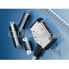
Connector Accessories Socket Housing 25 POS Polybutylene Terephthalate Black 014180

Connector Accessories Coding Key Straight 043347
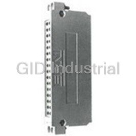
Connector Accessories Housing Cover Front Panel For Male Connector Bag 043551
Connector Accessories Guide Element For Male Connector 043553
Connector Accessories Guide Element Straight 043554
Connector Accessories Guide Element for Female Connector 043555
Request a Quote

The quote request has been received
Close

Facing challenges or have inquiries? Feel free to contact us!
Call Us +1-469-283-2440
What they say about us
FANTASTIC RESOURCE
One of our top priorities is maintaining our business with precision, and we are constantly looking for affiliates that can help us achieve our goal. With the aid of GID Industrial, our obsolete product management has never been more efficient. They have been a great resource to our company, and have quickly become a go-to supplier on our list!
Bucher Emhart Glass
EXCELLENT SERVICE
With our strict fundamentals and high expectations, we were surprised when we came across GID Industrial and their competitive pricing. When we approached them with our issue, they were incredibly confident in being able to provide us with a seamless solution at the best price for us. GID Industrial quickly understood our needs and provided us with excellent service, as well as fully tested product to ensure what we received would be the right fit for our company.
Fuji
HARD TO FIND A BETTER PROVIDER
Our company provides services to aid in the manufacture of technological products, such as semiconductors and flat panel displays, and often searching for distributors of obsolete product we require can waste time and money. Finding GID Industrial proved to be a great asset to our company, with cost effective solutions and superior knowledge on all of their materials, it’d be hard to find a better provider of obsolete or hard to find products.
Applied Materials
CONSISTENTLY DELIVERS QUALITY SOLUTIONS
Over the years, the equipment used in our company becomes discontinued, but they’re still of great use to us and our customers. Once these products are no longer available through the manufacturer, finding a reliable, quick supplier is a necessity, and luckily for us, GID Industrial has provided the most trustworthy, quality solutions to our obsolete component needs.
Nidec Vamco
TERRIFIC RESOURCE
This company has been a terrific help to us (I work for Trican Well Service) in sourcing the Micron Ram Memory we needed for our Siemens computers. Great service! And great pricing! I know when the product is shipping and when it will arrive, all the way through the ordering process.
Trican Well Service
GO TO SOURCE
When I can't find an obsolete part, I first call GID and they'll come up with my parts every time. Great customer service and follow up as well. Scott emails me from time to time to touch base and see if we're having trouble finding something.....which is often with our 25 yr old equipment.
ConAgra Foods