

 Manufacturers
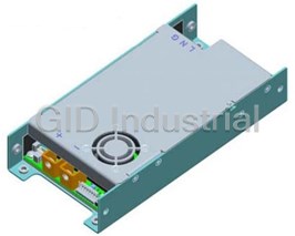
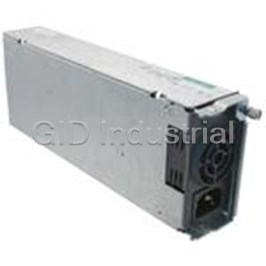
GE CRITICAL POWER CP2500AC54TEZ-B

Description
2500 W, Single Output, 54 VDC@25 A / 46.3 A / 37 A Enclosed AC-DC Power Supply
Part Number
CP2500AC54TEZ-B
Price
Request Quote
Manufacturer
GE CRITICAL POWER
Lead Time
Request Quote
Category
Circuit Protection » AC-DC Power Supply
Specifications
Manufacturer
GE Critical Power
Manufacturers Part #
CP2500AC54TEZ-B
Industry Aliases
150037800
Brand
GE Critical Power
Series
CP2500AC54TE
Factory Pack Quantity
1
Cooling Method
Air-Cooled
Dimensions
13.85 x 4.00 x 1.63"
Driving Method
Constant Voltage
Efficiency
96.2%
Input Type
AC
Input Voltage Nominal
100 VAC to 120 VAC / 200 VAC to 277 VAC
Isolation
1500 VAC
Mechanical Style
Hot-Swap
Mounting
Rack Mount
Number of Outputs
1
Operating Temperature
- 40 to + 55°C
Output Amps 1
25 A / 46.3 A / 37 A
Output Voltage V1 Nominal
54 VDC
Package Type
Enclosed
PFC
PFC
Power
2500 W
Subcategory
AC-DC Power Supply
Datasheet
CP2500AC54TEZ?TNR=Data%20Sheets%7CCP2500AC54TEZ%7CPDF&filename=CP2500AC54TE_DS_June_16_2014.pdf
340 KiB

Extracted Text
Data Sheet GE CP2500AC54TE Compact Power Line High Efficiency Rectifier Input: 100-120/200-277 Vac; Default Output: ±54 Vdc @ 2500W; 5 Vdc @ 4W Features Efficiency 96.2% 3 Compact 1RU form factor with 30 W/in density Constant power from 52 – 58Vdc 2500W from nominal 200 – 277Vac 1200W from nominal 100 – 120Vac Output voltage programmable from 42V – 58Vdc 2 PMBus compliant dual I C and RS485 serial busses 2 Isolated +5V Aux, signals and I C communications Power factor correction (meets EN/IEC 61000-3-2 and EN 60555-2 requirements) Output overvoltage and overload protection AC Input overvoltage and undervoltage protection Applications Over-temperature warning and protection 48Vdc distributed power architectures Redundant, parallel operation with active load sharing Routers/Switches Remote ON/OFF VoIP/Soft Switches Hot insertion/removal (hot plug) LAN/WAN/MAN applications Four front panel LED indicators † File servers UL* Recognized to UL60950-1, CAN/ CSA C22.2 No. 60950- ‡ 1, and VDE 0805-1 Licensed to IEC60950-1 Indoor wireless § CE mark meets 2006/95/EC directive Telecommunications equipment Internally controlled Variable-speed fan Enterprise Networks RoHS 6 compliant SAN/NAS/iSCSI applications Description The CP2500AC54TE Rectifier provides significant efficiency improvements in the Compact Power Line platform of Rectifiers. High-density front-to-back airflow is designed for minimal space utilization and is highly expandable for future 2 growth. The standard product is provided with both RS485 and dual-redundant I C communications busses that allow it to be used in a broad range of applications. These signals and the 5V auxiliary supply are isolated from the main output and frame ground. Feature set flexibility makes this rectifier an excellent choice for applications requiring modular ac-to- dc 48Vdc intermediate voltages, such as in distributed power. * UL is a registered trademark of Underwriters Laboratories, Inc. † CSA is a registered trademark of Canadian Standards Association. ‡ VDE is a trademark of Verband Deutscher Elektrotechniker e.V. § This product is intended for integration into end-user equipment. All the required procedures for CE marking of end-user equipment should be followed. (The CE mark is placed on selected products.) ** ISO is a registered trademark of the International Organization of Standards. June 18, 2014 ©2012 General Electric Company. All rights reserved. Data Sheet GE CP2500AC54TE Rectifier Input: 100-120/200-277 Vac; Default Output: ±54 Vdc @ 2500W; 5 Vdc @ 4W Electrical Specifications Input Parameter Min Typ Max Units Notes Startup Input Voltage Low-line Operation 90 High-line Operation 185 Operating Voltage Range Low-line Configuration 90 100, 110, 120 140 High-line Configuration 185 200 – 277 305 Vac Input Voltage Swell (no damage) 305 Input Frequency 47 66 Hz 10.9 At 110 Vac Input Current A 12 At 240 Vac Measured at 25°C for all line conditions; does not Inrush Transient 25 Apk 30 include X-Capacitors charging. Input Leakage Current 2.5 3.5 mA Measured at 265Vac, 60Hz Power Factor 0.96 0.98 From 50% to 100% load. With OR’ing function, aux 5V output, dual/redundant 1 Efficiency 30 – 90% of FL 94.5 96.2 % 2 I C and RS485 communications and POE isolation 20 Measurement starts at zero crossing of the ac voltage, Holdup Time ms and voltage decayed to 40V. 30 For loads below 1200W. Tested at nominal 115V and 230V . Complies to Ride thru 1/2 1 cycle CISPR24 standards Alarm issued via PFW signal going LO 5 ms prior to 2 Power Fail Warning 3 5 ms the main output decaying below 40Vdc. Main Output Parameter Min Typ Max Units Notes Output Power 1200 At low-line input from nominal 100-120Vac. 2500 W At high-line input from nominal 200-277Vac 2000 At nominal 277Vac and Tamb > 45C Default Set point 54 Vdc Output floats with respect to frame ground. -1 +1 0 – 45C, minimum load 2.5A 3 Overall Regulation % -2 +2 > 45C Output Voltage Set Range 44 58 Vdc Analog margining. 2 42 58 Vdc Set either by I C, RS485 Output current 1 25 At 1200W, 54V @ 100-120Vac. 1 46.3/48 At 2500W, 54V/52V @ 200-240Vac. A 1 37/38.4 At 2000W, 54V/52V @ 277Vac and T > 45C. amb 1 At 240Vrms and 25C. See efficiency curves at the end of this document. 2 Internal protection circuits may override the PFW signal and may trigger an immediate shutdown. 3 Includes all variations due to specified load range, drift, and environmental conditions. June 18, 2014 ©2012 General Electric Company. All rights reserved. Page 2 Data Sheet GE CP2500AC54TE CPL High Efficiency Rectifier Input: 100-120/200-277 Vac; Default Output: ±54 Vdc @ 2500W; 5 Vdc @ 4W Electrical Specifications (continued) Main Output (continued) Parameter Min Typ Max Units Notes Current Share Compared to the average output current delivered by a -5 5 %FL set of rectifiers. Valid for loads > 50% of FL Proportional Current Share Among CP Rectifiers of different output capacities. <7 %FL Loads > 50%of FL Output Ripple RMS (5Hz to 20MHz) 100 mVrms Measured with 20MHz scope bandwidth under any 4 Peak-to-Peak (5Hz to 20MHz) 250 mVp-p condition of loading. Minimum load is 1A. 5 Psophometric Noise 9 mVrms External Bulk Load Capacitance External capacitance can be increased but the rectifier 0 5,000 F may not meet its turn-ON rise time requirement. Turn-On Monotonic Turn_On from 30% to 100% of Vnom above - Delay 5 s 5°C operation. Monotonic Turn_On from 60% to 100% of 1 Rise Time - Standard (PMBus) 100 ms Vnom below -5°C operation. 6 -Telecom (RS-485) 5 s Overshoot 2 % Load Step Response dI/dt (output current slew rate) 1A/µs. I 50 %FL Settling time to within regulation requirements. Minimum load of 2.5 amperes required. V, V 285 2.0 VDC AC AC 3.2 V V, V ≥ 285 DC AC AC Response Time 2 ms Overload Power Limit – high line 2500 W Down to 52Vdc Power limit – low line 1200 W 7 Current limit > 41.5Vo - HL 51 55.7 Adc Hiccup mode with a 10% duty cycle enabled below 39Vdc. Latched mode current limit optional. 5 Current limit < 41.5V - HL 36 Adc o (FL = 48A @ 52V) Current limit - LL 26 Adc System Power Up Units should be able to be plugged in one at a time and guarantee system start up. Units should stay in current limit for approximately 20 seconds to guarantee restart. Over-voltage Delayed 60 Vdc 200msec delayed shutdown to be implemented. Immediate Latchoff 65 Vdc Instantaneous shutdown above this point. Three restart attempts may be implemented within a one minute window prior to a latched shutdown Over-temperature Warning 5 °C Implemented prior to commencement of an OT shutdown Shutdown 20 °C Below the maximum rating of the device being protected Auto-recoverable Temperature hysteresis of approximately 10°C provided between shutdown and restart. 4 500mVp-p above 280Vrms 1 Complies with GR947 which calls for a minimum rise time proportional to output load. 2 Complies with ANSI TI.523-2001 section 4.9.2 emissions max limit of 20mV flat unweighted wideband noise limits 6 Below -5°C, the rise time is approximately 5 minutes to protect the bulk capacitors. 7 Above 275V input, the current limit point changes at 45V. There is a 30 second delay prior to shifting to the lower limit. June 18, 2014 ©2012 General Electric Company. All rights reserved. Page 3 Data Sheet GE CP2500AC54TE CPL High Efficiency Rectifier Input: 100-120/200-277 Vac; Default Output: ±54 Vdc @ 2500W; 5 Vdc @ 4W Electrical Specifications (continued) Auxiliary Output Parameter Min Typ Max Units Notes Output Voltage Setpoint 5 Vdc Output Current 0.005 0.75 A Overall Regulation -10 +5 % Within ±5% when load is < 0.5A. Ripple and Noise 50 100 mVpk-pk 20MHz bandwidth Over-voltage Clamp 7 Vdc Over-current Limit 110 175 %FL Environmental, EMC, Reliability Specifications Environmental Parameter Min Typ Max Units Notes Ambient Temperature 8 9 Operating -40 55 °C Air inlet from sea level to 5,000 feet. Derating 1 2 °C Per 1,000 feet above 5,000 feet. Extended Operating Temperature 55 75 °C With 2%/°C power derating above 55°C. Storage Temperature -40 85 °C Humidity 5 95 % Relative humidity, non-condensing -60 4000 m For operation above 2500m (5000 ft.), maximum operating Altitude -200 13000 ft temperature is derated by 2°C per 305m (1000 ft.). Shock and Vibration IPC9592 sections 5.2.8 – 5.2.13 Earthquake Rating 4 Zone Per Telcordia GR-63-CORE, all floors, when installed in CP Shelf. Acoustic Noise 55 dBA Noise is proportional to fan speed, load and ambient temperature. Harmonic Emissions Per EN/IEC61000-3-2 10 Radiated Emissions Exceeds FCC and CISPR22 (EN55022) - Class A Conducted Emissions - ac Exceeds FCC and CISPR22 (EN55022) Class A Telcordia GR-1089-CORE - Class A by a 3dB margin ESD Error free per EN/IEC 61000-4-2 Level 3 (6 kV contact discharge, 8 kV air discharge). Radiated Immunity Error free per EN/IEC 61000-4-3 Level 3 (10 V/m). Electrical Fast Transient Burst Error free per EN/IEC 61000-4-4 Level 3 (2 kV, 5 kHz repetition rate) Lightning Surge, Error Free EN/IEC61000-4-5 Level 4 (4 kV common mode, 2 kV differential mode). Damage Free ANSI C62.41 Level A3 (6 kV common and differential mode) Line sags and interruptions IPC9592A issued May 2010 ; 1 cycle interruption or 25% sag (115V, 230V – nominal for UUT) for 2 seconds the output shall stay above 40Vdc at full load. [Note: An input sag below 80V may cause an immediate shutdown.] Conducted Immunity Error free per EN/IEC 61000-4-6 Level 3 (10Vrms). At ambient of 25°C at full load per Telcordia SR-332, issue 2, Reliability (calculated) 450,000 Hours Reliability Prediction for Electronic Equipment, Method I Case III. Isolation Input-Chassis/Signals 1500 Vrms Per EN60950. Input - Output 3000 Vrms Consult factory for testing to this requirement Output-Chassis 500 Vdc Internal Lineage standard, GR_947 Output-Chassis/Signals 2250 Vdc POE compliant Rectifier, Per IEEE802.3. 8 Designed to start and work at an ambient as low as -40°C, but may not meet operational limits until above -5°C 9 Output power is derated to 2kW for temperatures higher than 45C and input voltages higher than 285Vrms. 10 Radiated emissions compliance was met using a Lineage Power shelf. This shelf includes output common and differential mode capacitors that assist in meeting compliance. June 18, 2014 ©2012 General Electric Company. All rights reserved. Page 4 Data Sheet GE CP2500AC54TE CPL High Efficiency Rectifier Input: 100-120/200-277 Vac; Default Output: ±54 Vdc @ 2500W; 5 Vdc @ 4W Service Life 10 Years 25°C ambient, full load excluding fans. Status and Control Module Present Signal: This signal has dual functionality. It can be The Rectifier provides two means for monitor/control: analog or used to alert the system when a module is inserted. A 500Ω resistor 2 I C. is present in series between this signal and Logic_GRD. An external pull-up should not raise the voltage on the pin above 0.25Vdc. Details of analog controls are provided in this data sheet under Above 1Vdc, the write_protect feature of the EEPROM is enabled. Signal Definitions. GE Energy will provide separate application 2 notes on the I C protocol for users to interface to the CPL Protocol Select: Establishes the communications mode of the RECTIFIERs. Contact your local GE Energy representative for 2 rectifier, between analog/I C and RS485 modes. For RS485, connect details. 10kΩ pull-down resistor to 54_OUT(-DC). 2 Hot Plug Enable: On/Off control when I C communications are utilized as When rapidly extracting and reinserting modules care should configured by the Protocol pin. This pin must be pulled low to turn be taken to allow for discharging the internal bias supply so ON the rectifier. The rectifier will turn OFF if either the Enable or the that a predictable restart could be achieved. The way to ensure ON/OFF pin is released. This signal is referenced to Logic_GRD. that the circuit sufficiently discharges is to observe the spinning of the fans after an extraction. The unit should not be ON/OFF: This is a short pin utilized for hot-plug applications to reinserted until the fans stop spinning. ensure that the rectifier turns OFF before the power pins are disengaged. It also ensures that the rectifier turns ON only after the Without bleeding down internal bias the module may power pins have been engaged. Must be connected to V_OUT (-DC). remember its last assigned address and may not configure itself properly if reinserted into another slot. Output Signals Power_OK: This signal is HI when the main output is present and Control Definitions goes LO when the main output is not present. All signals are referenced to Logic_GRD unless otherwise noted. See the Signal Definitions Table at the end of this document for I_limit: This signal is HI when the main output is not in current limit further description of all the signals. and goes LO when current limit has activated. 2 Input Signals Alert #: I C interrupt signal. Margining: Set point of the Rectifier can be changed via this input pin. Programming can be either a voltage source or a Fault: This signal goes LO for any failure that requires Rectifier resistance divider. The margining pin is connected to 3.3Vdc via replacement. Some of these faults may be due to: a 10kΩ resistor inside the Rectifier. See graphs below. Fan failure -58 Over-temperature condition 3.3Vdc Over-temperature shutdown Over-voltage shutdown -46 Internal Rectifier Fault -44 Vcontrol 0 0.1 An open circuit on this pin reverts the voltage level back to the original setting. Software commanded margining overrides the hardware set point indefinitely or until the default setting is reinstated for example if input power and bias power have been removed from the module. June 18, 2014 ©2012 General Electric Company. All rights reserved. Page 5 Output Setpoint (Vdc) Vprogram 10k Data Sheet GE CP2500AC54TE CPL High Efficiency Rectifier Input: 100-120/200-277 Vac; Default Output: ±54 Vdc @ 2500W; 5 Vdc @ 4W Alarm Table Monitoring Signals Power Supply LED State (Referenced to Logic_GRD) AC OK DC OK Service Fault Condition Green Green Amber Red Fault OTW PFW Module Present OK 1 1 0 0 HI HI HI LO Thermal Alarm 1 1 1 0 HI LO HI LO (5C before shutdown) Thermal Shutdown 1 0 1 1 LO LO LO LO Defective Fan 1 0 0 1 LO HI LO LO Blown AC Fuse in Unit 1 0 0 1 LO HI LO LO 3 No AC <15mS (single unit) 0 1 0 0 HI HI LO LO AC Present but not within limits Blinks 0 0 0 HI HI LO LO 1 AC not present 0 0 0 0 HI HI LO LO Boost Stage Failure 1 0 0 1 LO HI LO LO Over Voltage Latched Shutdown 1 0 0 1 LO HI LO LO Over Current 1 Blinks 0 0 HI HI LO LO 2 Non-catastrophic Internal Failure 1 1 0 1 LO HI HI LO 4 1 Missing Module HI Standby (remote) 1 0 0 0 HI HI LO LO Service Request (PMBus mode) 1 1 Blinks 0 HI HI HI LO Communications Fault (RS485 mode) 1 1 0 Blinks HI HI HI LO 1 This signal is correct if the Rectifier is back biased from other Rectifiers in the shelf . 2 Any detectable fault condition that does not result in the power supply shutting down. For example, ORing FET failure, boost section out of regulation, etc. 3 Signal transition from HI to LO is output load dependent 4 Signal must be pulled HI external to the module Output Connector Mating Connector: right angle PWB mate – all pins: AMP 6450572-1, right angle PWB mate except pass-thru input power: AMP 6450378-1 A1 A6 P1 P7 Manufacturer part numbers: FCI 51939-568 SIGNAL OUTPUT POWER INPUT POWER 65 4 3 2 1 P7 P6 P5 P4 P3 P2 P1 PFW LOGIC_GRD UNIT_ADDR A SCL_0 MOD_PRES RS_485+ B SCL_1 OTW Alert#_0 Alert#_1 RS_485- 8V_INT V_OUT V_OUT V_OUT V_OUT EARTH LINE-2 LINE-1 C SDA_0 Margin Enable Reset Ishare Protocol ( - ) ( + ) ( + ) ( - ) (GND) (Neutral) (HOT) D SDA_1 Fault 5VA Power_Cap ON/OFF SHELF_ADDR Note: Connector is viewed from the rear positioned inside the rectifier Signal pins columns 1 and 2 are referenced to V_OUT (–) Signal pins columns 3 through 6 are referenced to Logic GRD Last to make-first to break shortest pin First make-last to break longest pin implemented in the mating connector Earth June 18, 2014 ©2012 General Electric Company. All rights reserved. Page 6 Data Sheet GE CP2500AC54TE CPL High Efficiency Rectifier Input: 100-120/200-277 Vac; Default Output: ±54 Vdc @ 2500W; 5 Vdc @ 4W Signal Definitions All hardware alarm signals (Fault, PFW, OTW, Power Capacity) are open drain FETs. These signals should be pulled HI to either 3.3V or 5V. Maximum sink current 5mA. An active LO signal (< 0.4Vdc) state. All signals are referenced to Logic GRD unless otherwise stated. Contact your Lineage Power representative for more details. Function Label Type Description 2 Output Enable Enable Input If shorted to LOGIC_GRD, the Rectifier output is enabled when using I C mode of operation. May also be toggled to reset a latched OFF Rectifier. Function not available in RS485 mode. Power Fail Warning PFW Output An open drain FET; normally HI, indicating output power is present. Changes to LO at least 5msec before the output voltage decays below 40Vdc. 2 2 I C Interrupt Alert#_0 Output Interrupt signal via I C lines indicating that service is requested from the host Alert#_1 controller. This signal pin is pulled up to 3.3V via a 10kΩ resistor and switches to active LO when an interrupt occurs. Rectifier Fault Fault Output Indicates that an internal fault exists. An open drain FET; normally HI, changes to LO. Module Present MOD_PRES Output Short pin, see Status and Control description for further information on this signal. ON/OFF ON/OFF Input Short pin, connects last and breaks first; used to activate and deactivate output during hot-insertion and extraction, respectively. Ref: Vout ( - ) Protocol select Protocol Input See Status and Control description for further information on this signal. Ref: Vout ( - ). Margining Margin Input Allows changing of output voltage through an analog voltage input or via resistor divider. Over-Temperature Warning OTW Output An open drain FET; normally HI, changes to LO approximately 5°C prior to thermal shutdown. Power Capacity POWER_CAP Output Open drain FET; Used to indicate Rectifier operation mode; HI indicates 2500W operation and LO indicates 1200W operation. Rectifier address Unit_addr Input Voltage level addressing of Rectifiers within a single shelf. Ref: Vout ( - ). Shelf Address Shelf_addr Input Voltage level addressing of Rectifiers within multiple shelves. Ref: Vout ( - ). Back bias 8V_INT Bi-direct Diode OR’ed 8Vdc drain; used to back bias microprocessors and DSP of failed Rectifier from operating Rectifiers. Ref: Vout ( - ). 2 2 Mux Reset Reset Input Resets the I C lines to I C line 0. Standby power 5VA Output 5V at 0.75A provided for external use by either adjacent power supplies or the using system. Current Share Ishare Bi-direct A single wire interface between each of the power unit forces them to share the load current. Ref: Vout ( - ). 2 2 I C Line 0 SCL_0, SDA_0 Input I C line 0. 2 2 I C Line 1 SCL_1, SDA_1 Input I C line 1. 2 I C Interrupt Alert# Output Goes active LO RS485 Line RS_485+ Bi-direct RS485 line. RS_485- June 18, 2014 ©2012 General Electric Company. All rights reserved. Page 7 Data Sheet GE CP2500AC54TE CPL High Efficiency Rectifier Input: 100-120/200-277 Vac; Default Output: ±54 Vdc @ 2500W; 5 Vdc @ 4W Front Panel LEDs 2 Analog Mode I C Mode RS485 Mode ON: Input ok Blinking: Input out of limits ON: Output ok Blinking: Overload ON: Over-temperature Warning ON: Over-temperature Warning ON: Over-temperature Warning Blinking: Service ON: Fault ! ON: Fault Blinking: Not communicating Dimensions 13.85 in. (351.2 mm) Rear View 4.00 in. (101.6 mm) 1.63 in. (41.4 mm) Top View Front View Physical Packaged weight 5.4/2.45 lbs/kgs Unpacked weight 4.8/2.18 lbs/kgs Heat release 100 Watts or 341 BTUs @ 80% load 153 Watts or 522 BTUs @ 100% load June 18, 2014 ©2012 General Electric Company. All rights reserved. Page 8 Data Sheet GE CP2500AC54TE CPL High Efficiency Rectifier Input: 100-120/200-277 Vac; Default Output: ±54 Vdc @ 2500W; 5 Vdc @ 4W Ordering Information Item Description Comcode CP2500AC54TEZ 54Vdc @ 50A, 5Vdc @ 0.75A, RoHS 6/6 CC109172680 CP2500AC54TEZ-B Same as above with a black faceplate 150037800 Accessories Item Description Comcode Power supply interface board 150037482 Isolated Interface Adapter Kit – interface between a USB 150036482 2 port and the I C connector on the power supply interface board Graphical User Interface download demonstrating the 2 redundant I C capabilities of the power supply. The site below downloads the GE Digital Power Insight™ software tools, including the cpgui_l. When the download is complete, icons for the various utilities will appear on the desktop. Click on cpgui_l.exe to start the program after the download is complete. http://apps.geindustrial.com/publibrary/checkout/Software% 7CCPSW-DPI%7Cgeneric Graphical User Interface Manual; The GUI download created a directory In that directory start the DPI_manual.pdf file. June 18, 2014 ©2012 General Electric Company. All rights reserved. Page 9 Data Sheet GE CP2500AC54TE CPL High Efficiency Rectifier Input: 100-120/200-277 Vac; Default Output: ±54 Vdc @ 2500W; 5 Vdc @ 4W Typical Efficiency Contact Us For more information, call us at USA/Canada: +1 888 546 3243, or +1 972 244 9288 Asia-Pacific: +86.021.54279977*808 Europe, Middle-East and Africa: +49.89.878067-280 India: +91.80.28411633 www.gecriticalpower.com GE Critical Power reserves the right to make changes to the product(s) or information contained herein without notice, and no liability is assumed as a result of their use or application. No rights under any patent accompany the sale of any such product(s) or information. June 18, 2014 ©2014 General Electric Company. All International rights reserved. Page 10
Frequently asked questions
How does Electronics Finder differ from its competitors?

Is there a warranty for the CP2500AC54TEZ-B?
Which carrier will Electronics Finder use to ship my parts?
Can I buy parts from Electronics Finder if I am outside the USA?
Which payment methods does Electronics Finder accept?
Why buy from GID?

Quality
We are industry veterans who take pride in our work

Protection
Avoid the dangers of risky trading in the gray market

Access
Our network of suppliers is ready and at your disposal

Savings
Maintain legacy systems to prevent costly downtime

Speed
Time is of the essence, and we are respectful of yours
Related Products
400W, 24V, UNIVERSAL AC INPUT FRONT END, TOP SIDE FAN
400 W, Single Output, 24 VDC@16.7 A Open Frame AC-DC Power Supply
850 W, Single Output, 12 VDC@71 A Enclosed AC-DC Power Supply
850 W, Single Output, 12 VDC@71 A Enclosed AC-DC Power Supply
850W, 12V, UNIVERSAL AC INPUT FRONT END, CLASS A EMI
850 W, Single Output, 12 VDC@71 A Enclosed AC-DC Power Supply
Request a Quote

The quote request has been received
Close

Facing challenges or have inquiries? Feel free to contact us!
Call Us +1-469-283-2440
What they say about us
FANTASTIC RESOURCE
One of our top priorities is maintaining our business with precision, and we are constantly looking for affiliates that can help us achieve our goal. With the aid of GID Industrial, our obsolete product management has never been more efficient. They have been a great resource to our company, and have quickly become a go-to supplier on our list!
Bucher Emhart Glass
EXCELLENT SERVICE
With our strict fundamentals and high expectations, we were surprised when we came across GID Industrial and their competitive pricing. When we approached them with our issue, they were incredibly confident in being able to provide us with a seamless solution at the best price for us. GID Industrial quickly understood our needs and provided us with excellent service, as well as fully tested product to ensure what we received would be the right fit for our company.
Fuji
HARD TO FIND A BETTER PROVIDER
Our company provides services to aid in the manufacture of technological products, such as semiconductors and flat panel displays, and often searching for distributors of obsolete product we require can waste time and money. Finding GID Industrial proved to be a great asset to our company, with cost effective solutions and superior knowledge on all of their materials, it’d be hard to find a better provider of obsolete or hard to find products.
Applied Materials
CONSISTENTLY DELIVERS QUALITY SOLUTIONS
Over the years, the equipment used in our company becomes discontinued, but they’re still of great use to us and our customers. Once these products are no longer available through the manufacturer, finding a reliable, quick supplier is a necessity, and luckily for us, GID Industrial has provided the most trustworthy, quality solutions to our obsolete component needs.
Nidec Vamco
TERRIFIC RESOURCE
This company has been a terrific help to us (I work for Trican Well Service) in sourcing the Micron Ram Memory we needed for our Siemens computers. Great service! And great pricing! I know when the product is shipping and when it will arrive, all the way through the ordering process.
Trican Well Service
GO TO SOURCE
When I can't find an obsolete part, I first call GID and they'll come up with my parts every time. Great customer service and follow up as well. Scott emails me from time to time to touch base and see if we're having trouble finding something.....which is often with our 25 yr old equipment.
ConAgra Foods