

 Manufacturers
IDEC CORPORATION AL6H-M23P-W
Description
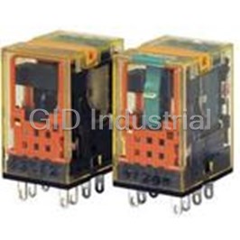
Electromechanical Relay 220/240VAC 18.23KOhm 10A DPDT(27.5x21x41.6)mm Socket General Purpose Relay
AL6H-M23P-W
Part Number
AL6H-M23P-W
Price
Request Quote
Manufacturer
IDEC CORPORATION
Lead Time
Request Quote
Category
Relays and I/O Modules » Relay Other
Specifications
Manufacturer
IDEC Corporation
Manufacturers Part #
AL6H-M23P-W
Industry Aliases
RU2S-M-A220
Sub-Category
Other Relays
Factory Pack Quantity
1
Datasheet

Extracted Text
RU Relays & Sockets RU Series Universal Relays Key features: • Full featured universal miniature relays • Designed with environment taken into consideration • Two terminal styles: plug-in and PCB mount • Non-polarized LED indicator • No internal wires, lead-free construction • Cadmium-free contacts • Mechanical flag indicator • Manual latching lever with color coding for AC or DC coil • Snap-on yellow marking plate; optional marking plates are available in four other colors • Maximum contact ratings: 10A (RU2), 6A (RU4), 3A (RU42) • UL Recognized, CSA Certified, EN Compliant EN61810-1 With Latching or Momentary Lever Latching and Momentary Lever Using the lever, operation can be checked without energiz- Mechanical Indicator* ing the coil. The lever is color coded for AC and DC coils. The contact position can be confirmed through Latching Momentary the five small windows. AC coil: Orange Red Marking Plate DC coil: Green Blue Standard yellow marking plate is easily replaced with optional marking plates in four colors for easy identification of relays. In Normal Operation LED Indicator* Non-polarized green LED indicator is standard provision for plug-in terminal, latching lever types Note: Turn off the power to the relay coil when using the latching lever. After checking the operation, return the latching lever in the normal position. Standard (without lever) AC/DC Color Marking For identification of AC or DC coils. AC coil: Yellow DC coil: Blue Coil Voltage Tape Color Mechanical Indicator* 24V AC White Marking Plate 100 to 110V AC Clear 110 to 120V AC Blue LED Indicator* Non-polarized green LED indicator is standard 200 to 220V AC Black provision for plug-in terminal types. 220 to 240V AC Red 24V DC Green 6V DC AC Coil DC Coil 12V DC Voltage marking on yellow tape 48V DC *Not available on PCB type. 110V DC www.IDEC.com 790 Circuit Breakers Terminal Blocks Contactors Timers Relays & Sockets Signaling Lights Switches & Pilot Lights Switches & Pilot Lights Signaling Lights Relays & Sockets Timers Contactors Terminal Blocks Circuit Breakers RU Relays & Sockets Part Number Selection Part Number Coil Voltage Code Contact Model Standard With Latching Lever With Momentary Lever (Standard Stock in bold) A24, A110, A220 DPDT (10A) Standard RU2S-C-0 RU2S-0 RU2S-M-0 D6, D12, D24, D48, D110 With RC (AC coil only) RU2S-CR-0 RU2S-R-0 RU2S-MR-0 A110, A220 With diode (DC coil only) D6, D12, D24, D48, D110 RU2S-CD-0 RU2S-D-0 RU2S-MD-0 A24, A110, A220 PCB RU2V-NF-0 — — D6, D12, D24, D48, D110 A24, A110, A220 4PDT (6A) Standard RU4S-C-0 RU4S-0 RU4S-M-0 D6, D12, D24, D48, D110 With RC (AC coil only) A110, A220 RU4S-CR-0 RU4S-R-0 RU4S-MR-0 With diode (DC coil only) D6, D12, D24, D48, D110 RU4S-CD-0 RU4S-D-0 RU4S-MD-0 A24, A110, A220 PCB — — RU4V-NF-0 D6, D12, D24, D48, D110 A24, A110, A220 4PDT Bifurcated (3A) Standard RU42S-C-0 RU42S-0 RU42S-M-0 D6, D12, D24, D48, D110 With RC (AC coil only) RU42S-CR-0 RU42S-R-0 RU42S-MR-0 A110, A220 With diode (DC coil only) RU42S-CD-0 RU42S-D-0 RU42S-MD-0 D6, D12, D24, D48, D110 A24, A110, A220 PCB — — RU42V-NF-0 D6, D12, D24, D48, D110 1. Plug-in terminal models have an LED indicator and a mechanical indicator as standard. Ordering Information 2. PCB models do not have an LED indicator or a mechanical indicator. When ordering, specify the Part No. and coil voltage code: (example) RU2S-C A110 Part No. Coil Voltage Code Coil Voltage Table Coil Voltage Code A24 A110 A220 D6 D12 D24 D48 D110 Coil Rating 24V AC 110-120V AC 220-240V AC 6V DC 12V DC 24V DC 48V DC 110V DC Sockets Spring Clamp Standard DIN Finger-safe DIN Relays Panel Mount PCB Mount DIN Rail Mount Rail Mount Rail Mount SM2S-61 RU2S (DPDT) SU2S-11L SM2S-05 SM2S-05C SM2S-62 SY4S-51 RU4S (4PDT) SY4S-61 SU4S-11L SY4S-05 SY4S-05C RU42S (4PDT) SY4S-62 800-262-IDEC (4332) • USA & Canada 791 RU Relays & Sockets Hold Down Springs & Clips For Through For DIN Appearance Item Relay Panel & PCB Mount Socket Mount Socket Pullover Wire RU2S/RU4S/ SY4S-02F1 SY4S-51F1 Spring RU42S Leaf Spring RU2S/RU4S/ SFA-202* SFA-302* (side latch) RU42S Leaf Spring RU2S/RU4S/ SFA-101* SFA-301* Note: Order 2 pieces for each relay (top latch) RU42S Accessories Name Part Number Color Code * Marking Plate RU9Z-P* A (orange), G (green), S (blue), W (white), Y (yellow) Specify a color code when ordering. The marking plate can be removed from the relay by inserting a flat screwdriver under the marking plate. Specifications Model (Contact) RU2 (DPDT) RU4 (4PDT) RU42 (4PDT-bifurcated) Contact Material Silver alloy Silver (gold clad) Silver-nickel (gold clad) 1 Contact Resistance 50 mΩ maximum Minimum 24V DC, 5 mA 1V DC, 1 mA 1V DC, 0.1 mA 2 Applicable Load (reference value) 3 Operating Time 20 ms maximum 3 Release Time 20 ms maximum Power Consumption AC: 1.1 to 1.4VA (50 Hz), 0.9 to 1.2VA (60 Hz) DC: 0.9 to 1.0W Insulation Resistance 100MΩ minimum (500V DC megger) Between contact and coil: 2500V AC, 1 minute Between contacts of different poles: Dielectric Strength 2500V AC, 1 minute 2000V AC, 1 minute Between contacts of the same pole: 1000V AC, 1 minute Electrical: 1800 operations/h maximum Operating Frequency Mechanical: 18,000 operations/h maximum Damage limits: 10 to 55 Hz, amplitude 0.5 mm Vibration Resistance Operating extremes: 10 to 55 Hz, amplitude 0.5 mm 2 Damage limits: 1000 m/s (100G) Shock Resistance 2 Operating extremes: 150 m/s (15G) AC: 50,000,000 operations Mechanical Life 50,000,000 operations DC: 100,000,000 operations 4 Electrical Life See table on page 794 Operating PCB model: –55 to +70°C (no freezing) 5 Temperature Blade model: –55 to +60°C (no freezing) Operating Humidity 5 to 85% RH (no condensation) Weight Approx. 35g 1. Measured using 5V DC, 1A voltage drop method 4. Contact Load and Electrical Life (at ambient temperature 20°C) 2. Measured at operating frequency of 120 operations/min (failure rate level P, reference value) 5. Measured at the rated voltage. 3. Measured at the rated voltage (at 20°C), excluding contact bouncing; Release time of AC relays with RC: 25 ms maximum Release time of DC relays with diode: 40 ms maximum www.IDEC.com 792 Circuit Breakers Terminal Blocks Contactors Timers Relays & Sockets Signaling Lights Switches & Pilot Lights Switches & Pilot Lights Signaling Lights Relays & Sockets Timers Contactors Terminal Blocks Circuit Breakers RU Relays & Sockets Accessories Item Appearance Use with Part No. Remarks The BNDN1000 is designed to accommodate DIN mount sockets. Aluminum Made of durable extruded aluminum, the BNDN1000 measures 0.413 DIN Rail All DIN rail sockets BNDN1000 (10.5mm) in height and 1.37 (35mm) in width (DIN standard). Standard (1 meter length) length is 39” (1,000mm). DIN Rail End DIN rail BNL5 9.1 mm wide. Stop Replacement Horseshoe clip for DIN rail For use on DIN rail mount socket when using pullover wire hold down Hold-Down Y778-011 sockets spring. 2 pieces included with each socket. Spring Anchor Coil Ratings Rated Current (mA) Operating Characteristics (values at 20°C) Coil ±15% (at 20°C) Coil Resistance (Ω) Rated Voltage (V) Voltage ±10% (at 20°C) Maximum Continuous Code 50 Hz 60 Hz Pickup Voltage Dropout Voltage Applied Voltage 24 A24 49.3 42.5 164 AC 110-120 A110 8.4-10.0 7.1-8.2 4,550 110% 80% maximum 30% minimum (50/60 Hz) 220-240 A220 4.2-5.0 3.6-4.2 18,230 6 D6 155 40 12 D12 80 160 DC 24 D24 44.7 605 110% 80% maximum 10% minimum 48 D48 18 2,560 110 D110 8.9 12,100 1. The rated current includes the current of the LED indicator. Surge Suppressor Ratings UL and c-UL Ratings Model Ratings Resistive General Use Horse Power Rating Voltage RC series circuit RU2 RU4 RU42 RU2 RU4 RU42 RU2 RU4 RU42 AC Coil With RC R: 20 kΩ, C: 0.033 µF 250V AC 10A — 3A — 6A — — 1/10HP — Diode reverse voltage: 1000V 30V DC 10A 6A 3A — — — — — — DC Coil With Diode Diode forward current: 1A CSA Ratings TÜV Ratings Contact Ratings Resistive Resistive Inductive Voltage Voltage Maximum Contact Capacity RU42 RU2 RU4 RU42 RU2 RU4 RU42 Allowable Contact Power Rated Load Continuous Voltage 250V AC 3A 250V AC 10A 6A 3A 5A 0.8A 0.8A Contact Current (V) Resistive Load Inductive Load Res. Load Ind. Load 30V DC 3A 30V DC 10A 6A 3A 5A 1.5A 1.5A 2500VA AC 1250VA AC 250 AC 10A 5A DPDT 10A 300W DC 150W DC 30 DC 10A 5A 1500VA AC 600VA AC 250 AC 6A 0.8A 4PDT 6A 180W DC 90W DC 30 DC 6A 1.5A 750VA AC 200VA AC 250 AC 3A 0.8A 4PDT 3A bifurcated 90W DC 45W DC 30 DC 3A 1.5A 1. On 4PDT relays, the maximum allowable total current of neighboring two poles is 6A. At the rated load, make sure that the total current of neighboring two poles does not exceed 6A (3A + 3A = 6A). 2. Inductive load for the rated load — cos ø = 0.3, L/R = 7 ms 800-262-IDEC (4332) • USA & Canada 793 RU Relays & Sockets Socket Specifications Sockets Terminal Electrical Rating Wire Size Torque SU2S-11L Spring clamp terminals 250V/10A 24-16 AWG — SU4S-11L Spring clamp terminals 250V/6A (using RU4), 10A (using RU2) 24-16 AWG — SM2S-05 M3 screw with captive wire clamp 300V, 10A Maximum up to 2–#14AWG 5.5 - 9in•lbs DIN Rail Mount Sockets SM2S-05C M3 screw with captive wire clamp, fingersafe 300V, 10A Maximum up to 2–#14AWG 5.5 - 9in•lbs SY4S-05 M3 screw with captive wire clamp 300V, 7A (using RU4), 10A (using RU2) Maximum up to 2–#14AWG 5.5 - 9in•lbs SY4S-05C M3 screw with captive wire clamp, fingersafe 300V, 7A (using RU4), 10A (using RU2) Maximum up to 2–#14AWG 5.5 - 9in•lbs Through Panel SY4S-51 Solder 300V, 7A — — Mount Socket SY4S-61 PCB mount 300V, 7A — — PCB Mount Socket SY4S-62 PCB mount 250V, 7A — — Electrical Life Curves RU2 (Resistive Load) RU4 (Resistive Load) RU42 (Resistive Load) 250V AC 250V AC 250V AC 30V DC 30V DC 30V DC 110V DC 110V DC 110V DC 1000 1000 100 100 100 10 10 10 1 1 1 0.1 0.5 1 5 10 0.02 0.1 0.5 1 3 6 0.1 0.5 1 3 6 Load Current (A) Load Current (A) Load Current (A) RU2 (Inductive Load) RU4 (Inductive Load) RU42 (Inductive Load) 250V AC/30V DC 250V AC 250V AC 110V DC 30V DC 30V DC 110V DC 110V DC 1000 100 100 100 10 10 10 AC: cos ø = 0.3 DC: L/R = 7 ms AC: cos ø = 0.3 AC: cos ø = 0.3 DC: L/R = 7 ms DC: L/R = 7 ms 1 1 1 0.1 0.5 1 5 10 0.02 0.1 0.5 0.02 0.1 0.5 Load Current (A) Load Current (A) Load Current (A) Maximum Switching Current RU2 RU4 RU42 (Bifurcated) AC resistive AC inductive (cos ø = 0.3) 10 5 DC resistive 1 DC inductive 0.1 L/R = 7 ms 10 30 100 250 500 Load Voltage (V) www.IDEC.com 794 Circuit Breakers Terminal Blocks Contactors Timers Relays & Sockets Signaling Lights Switches & Pilot Lights Load Current (A) (¥ 10,000 operations) (¥ 10,000 operations) (¥ 10,000 operations) (¥ 10,000 operations) (¥ 10,000 operations) (¥ 10,000 operations) Switches & Pilot Lights Signaling Lights Relays & Sockets Timers Contactors Terminal Blocks Circuit Breakers RU Relays & Sockets Ambient Temperature vs. Temperature Rise Curves RU2 (AC Coil, 50 Hz) RU2 (AC Coil, 60 Hz) RU2 (DC Coil) 120 120 120 110 110 110 100 100 100 90 90 90 Load current 80 80 80 10A ¥ 2 poles Load current Load current 70 70 70 10A ¥ 2 poles 10A ¥ 2 poles 60 60 60 50 50 50 Load current 40 40 40 5A ¥ 2 poles Load current Load current 30 30 30 5A ¥ 2 poles No load current 5A ¥ 2 poles 20 20 20 No load current No load current 10 10 10 0 10 20 30 40 50 60 70 010203040506070 010203040506070 Ambient Temperature (C) Ambient Temperature (C) Ambient Temperature (C) RU4/RU42 (AC Coil, 50 Hz) RU4/RU42 (AC Coil, 60 Hz) RU4/RU42 (DC Coil) 120 120 120 110 110 110 100 100 100 90 90 90 80 80 80 Load current 70 6A ¥ 2 poles 70 70 Load current Load current 6A ¥ 2 poles 60 60 60 6A ¥ 2 poles 50 50 50 Load current 40 40 40 3A ¥ 4 poles Load current 30 30 Load current 30 3A ¥ 4 poles No load current 3A ¥ 4 poles No load current 20 20 20 No load current 10 10 10 010203040506070 0 10 20 30 40 50 60 70 0 10 20 30 40 50 60 70 Ambient Temperature (C) Ambient Temperature (C) Ambient Temperature (C) The above temperature rise curves show the characteristics when 100% the rated coil voltage is applied. The heat resistance of the coil is 120°C. The slant dashed line indicates the allowable temperature rise for the coil at different ambient temperatures. Load current 6A x 2 poles is for the RU4 models only. 800-262-IDEC (4332) • USA & Canada 795 Temperature Rise (C) Temperature Rise (C) Temperature Rise (C) Temperature Rise (C) Temperature Rise (C) Temperature Rise (C) RU Relays & Sockets Internal Connection (View from Bottom) RU2S-* Standard RU2S-*R with RC RU2S-*D With Diode RU2V-NF-* (1)12 (4)42 (1)12 (4)42 (5)14 (8)44 (5)14 (8)44 (9)11 (12)41 (9)11 (12)41 (13)A1 (14)A2 (13)A1 (14)A2 24V DC coil or less 24V AC/DC coil or less (1)12 (4)42 (1)12 (4)42 (5)14 (8)44 (5)14 (8)44 (9)11 (12)41 (9)11 (12)41 (13)A1 (14)A2 (13)A1 (14)A2 Over 24V AC/DC coil Over 24V DC coil RU4S-*/RU42S-* Standard RU4S-*R/RU42S-*R With RC RU4S-*D/RU42S-*D With Diode RU4V-NF-*/RU42V-NF-* (1)12 (2)22 (3)32 (4)42 (1)12 (2)22 (3)32 (4)42 (1)12 (2)22 (3)32 (4)42 (1)12 (2)22 (3)32 (4)42 (5)14 (6)24 (7)34 (8)44 (5)14 (6)24 (7)34 (8)44 (5)14 (6)24 (7)34 (8)44 (5)14 (6)24 (7)34 (8)44 (9)11 (10)21 (11)31 (12)41 (9)11 (10)21 (11)31 (12)41 (9)11 (10)21 (11)31 (12)41 (9)11 (10)21 (11)31 (12)41 (14)A2 (14)A2 (14)A2 (14)A2 (13)A1 (13)A1 (13)A1 (13)A1 24V DC coil or less 24V AC/DC coil or less (1)12 (2)22 (3)32 (4)42 (1)12 (2)22 (3)32 (4)42 (5)14 (6)24 (7)34 (8)44 (5)14 (6)24 (7)34 (8)44 (9)11 (10)21 (11)31 (12)41 (9)11 (10)21 (11)31 (12)41 (13)A1 (14)A2 (14)A2 (13)A1 Mechanical Indicator Window Marking Plate (yellow) Over 24V AC/DC coil Over 24V DC coil Marking Plate (yellow) Color Marking Dimensions (mm) Latching LED Indicator AC: Yellow (green) Lever DC: Blue AC: Orange RU2S RU2V DC: Green Marking Plate Marking Plate Removal Slot Removal Slot 13.2 0.8 0.5 2.6 2.6 0.5 ø1.2 ¥ 2.2 Hole 27.5 27.5 Mounting Hole Layout 7.0 Marking plate removal slot is provided only on one side. Insert a flat screwdriver into the slot to remove the marking plate. 6.4 4.1 12.7 All dimensions in mm. www.IDEC.com 796 8-ø1 Holes Circuit Breakers Terminal Blocks Contactors Timers Relays & Sockets Signaling Lights Switches & Pilot Lights 21.0 14 5 8 912 13 14 6.4 35.0 21.0 13.2 4.0 35.0 0.5 Switches & Pilot Lights Signaling Lights Relays & Sockets Timers Contactors Terminal Blocks Circuit Breakers Mechanical Indicator Window RU Relays & Sockets Marking Plate (yellow) Marking Plate (yellow) Color Marking Latching LED Indicator AC: Yellow Dimensions con’t (mm) Lever (green) DC: Blue AC: Orange RU4S/RU42S RU4V/RU42V DC: Green Marking Plate Marking Plate Removal Slot Removal Slot 3-4.4 0.5 2.6 0.5 0.8 2.6 ø1.2 × 2.2 Hole 27.5 27.5 Marking plate removal slot is provided only on one side. Mounting Hole Layout Insert a flat screwdriver into the slot to remove the marking 7.0 plate. 6.4 4.1 12.7 All dimensions in mm. Spring Clamp DIN Rail Mount Sockets SU2S-11L SU4S-11L 31 31 Terminal Arrangement Terminal Arrangement 12 9 12 11 10 9 8 5 8 7 6 5 2-ø3.2 2-ø3.2 Mounting Holes Mounting Holes 24.0 4 1 24.0 43 21 14 13 14 13 32 32 Ring terminals Ring terminals (Top View) (Top View) 38.3 38.3 cannot be used. cannot be used. Standard DIN Rail Mount Sockets SM2S-05 SY4S-05 30 31.5 30 31.5 6 DIN Rail 6 18 18 DIN Rail M3 Terminal (BNDN) Terminal Arrangement M3 Terminal (BNDN) Terminal Arrangement Screw 2-ø4.2 Mounting Holes Screw 8 7 6 5 8 5 (or M4 Tapped Holes) 2-ø4.2 Mounting Holes 4 3 2 1 4 1 (or M4 Tapped Holes) 26 26 4 max. 4.8 min. 14 13 14 13 4 max. 4.8 min. 12 11 10 9 12 9 ( ) Top View 18.5 (Top View) 18.5 5.9 max. 5.9 max. 26 25 26 25 ø3.2 min. ø3.2 min. 800-262-IDEC (4332) • USA & Canada 797 14-ø1 Holes 80 3 62 0.7 4.4 28.8 4.2 45 37.5 21.0 1 2 3 4 5 6 7 8 9 10 11 12 13 14 6.4 35.0 3 62 0.7 80 4.4 28.8 4.2 21.0 45 37.5 4.0 35.0 4.4 13.2 0.5 13.2 13.2 8.8 4.4 RU Relays & Sockets Dimensions con’t (mm) Finger-safe DIN Rail Mount Sockets SM2S-05C SY4S-05C 30 30 35.5 35.5 DIN Rail M3 Terminal DIN Rail 6 6 25 (BNDN) M3 Terminal 25 Screw (BNDN) Terminal Arrangement Terminal Arrangement Screw 6 5 8 7 2-ø4.2 Mounting Holes 2-ø4.2 Mounting Holes 18 8 5 18 (or M4 Tapped Holes) 4 3 2 1 (or M4 Tapped Holes) 4 1 26 26 14 13 14 13 12 11 10 9 12 9 Ring terminals ( ) Ring terminals Top View ( ) cannot be used. Top View cannot be used. 18.2 26 18.2 26 29 29 PCB Mount Sockets SM2S-61 SM2S-62 Terminal Arrangement 13.2 8.2 min.** 13.8 min. Terminal Arrangement 1 4 1 4 5 8 5 8 9 12 9 12 13 14 13 14 27 3 (Bottom View) 21.2 3 (Bottom View) 9-ø2 holes 11 11 9-ø2 holes 15 15 (Tolerance 0.1) (Tolerance 0.1) * 19.2 min. when using 1.5 hold-down springs 1.5 * 17.2 min. when using a hold-down spring. 21.2 13.2 min. when using a hold-down spring for ** the relay with check button. SY4S-61 SY4S-62 13.2 8.2 min.** 13.8 min. 8.8 4.4 Terminal Arrangement Terminal Arrangement 3 1 2 4 1 2 3 4 5 6 7 8 5 6 7 8 9 10 11 12 9 10 11 12 13 14 13 14 21.2 3 (Bottom View) 27 3 (Bottom View) 15-ø2 holes 11 11 15 15-ø2 holes (Tolerance 0.1) 15 (Tolerance 0.1) * 19.2 min. when using 1.5 * 1.5 17.2 min. when using a hold-down spring. hold-down springs 13.2 min. when using a hold-down spring for * * 21.2 the relay with check button Through Panel Mount Socket SY4S-51 Panel Thickness: +0.5 [27 (N–1) + 21.4] 0 1 to 2 Terminal Arrangement 1 2 3 4 5 7 6 8 9 10 11 12 13 14 27 3 (Bottom View) N: No. of sockets mounted 11 18.7 * 10.4 min. when using hold-down springs 2.4 21.2 www.IDEC.com 798 ø5.5 ø 5.5 Circuit Breakers Terminal Blocks Contactors Timers Relays & Sockets Signaling Lights Switches & Pilot Lights 31 1.6 64 31 31 4.2 0.3 2 0.3 46 25.4 0.3 25.4 25.4 14.2 min.* 16.8 10.4 14.2 min.* 16.8 4.1 +0.2 1.4 5.4 min.* 0 10.4 25.6 1.4 4.1 9 9 1.6 64 29 29 4.2 0.3 2 0.3 46 12.2 min.* 16.8 10.4 1.4 4.1 16.8 12.2 min.* 10.4 1.4 4.1 9 9 Switches & Pilot Lights Signaling Lights Relays & Sockets Timers Contactors Terminal Blocks Circuit Breakers Operating Instructions Relays & Sockets Operating Instructions Operating Instructions Driving Circuit for Relays Protection for Relay Contacts 1. To ensure correct relay operation, apply rated voltage to the relay coil. 1. The contact ratings show maximum values. Make sure that these values are not exceeded. When an inrush current flows through the load, the contact 2. Input voltage for the DC coil: may become welded. If this is the case, connect a contact protection circuit, A complete DC voltage is best for the coil power to make sure of stable relay such as a current limiting resistor. operation. When using a power supply containing a ripple voltage, suppress the ripple factor within 5%. When power is supplied through a rectification 2. Contact protection circuit: circuit, the relay operating characteristics, such as pickup voltage and dropout When switching an inductive load, arcing causes carbides to form on the voltage, depend on the ripple factor. Connect a smoothing capacitor for better contacts, resulting in increased contact resistance. In consideration of contact operating characteristics as shown below. reliability, contact life, and noise suppression, use of a surge absorbing circuit is recommended. Note that the release time of the load becomes slightly Pulsation longer. Check the operation using the actual load. Incorrect use of a contact protection circuit will adversely affect switching characteristics. Four typical Smoothing Emin Emax Emean DC Capacitor examples of contact protection circuits are shown in the following table: + R Relay Emax – Emin – Ripple Factor (%)¥ 100% This protection circuit can be used when the load Emean Emax = Maximum of pulsating current impedance is smaller than the RC impedance in an Emin = Minimum of pulsating current AC load power circuit. Emean = DC mean value Power Ind. Load CR • R: Resistor of approximately the same resistance value as the load 3. Leakage current while relay is off: • C:0.1 to 1 µF When driving an element at the same time as the relay operation, special consideration is needed for the circuit design. As shown in the incorrect This protection circuit can be used for both AC and DC load power circuits. circuit below, leakage current (Io) flows through the relay coil while the relay R: Resistor of approximately the same resistance is off. Leakage current causes coil release failure or adversely affects the value as the load vibration resistance and shock resistance. Design a circuit as shown in the C: 0.1 to 1 µF correct example. This protection circuit can be used for DC load power + Incorrect Correct circuits. Use a diode with the following ratings. TE R Power Reverse withstand voltage: Power voltage of the R D Ind. Load load circuit x 10 – Io Forward current: More than the load current This protection circuit can be used for both AC and DC load power circuits. 4. Surge suppression for transistor driving circuits: For a best result, when using a power voltage of 24 When the relay coil is turned off, a high-voltage pulse is generated, causing a Power Ind. Load to 48V AC/DC, connect a varistor across the load. transistor to deteriorate and sometimes to break. Be sure to connect a diode When using a power voltage of 100 to 240V AC/DC, to suppress the back electromotive force. Then, the coil release time becomes connect a varistor across the contacts. slightly longer. To shorten the coil release time, connect a Zener diode 3. Do not use a contact protection circuit as shown below: between the collector and emitter of the transistor. Select a Zener diode with a Zener voltage slightly higher than the power voltage. This protection circuit is very effective in arc suppression when Back emf suppressing diode opening the contacts. But, the capacitor is charged while the C contacts are opened. When the contacts are closed, the capacitor + Load Power R Relay is discharged through the contacts, increasing the possibility of – contact welding. This protection circuit is very effective in arc suppression when C Load opening the contacts. But, when the contacts are closed, a current Power flows to charge the capacitor, causing contact welding. Generally, switching a DC inductive load is more difficult than switching a DC resistive load. Using an appropriate arc suppressor, however, will improve the switching characteristics of a DC inductive load. Soldering 1. When soldering the relay terminals, use a soldering iron of 30 to 60W, and quickly complete soldering (within approximately 3 seconds). 2. Use a non-corrosive rosin flux. 800-262-IDEC (4332) • USA & Canada 817 Varistor Diode RC Varistor Operating Instructions Relays & Sockets Operating Instructions con’t Other Precautions 2. UL and CSA ratings may differ from product rated values determined by IDEC. 1. General notice: To maintain the initial characteristics, do not drop or shock the relay. 3. Do not use relays in the vicinity of strong magnetic field, as this may affect relay operation. The relay cover cannot be removed from the base during normal operation. To maintain the initial characteristics, do not remove the relay cover. Use the relay in environments free from condensation, dust, sulfur dioxide (SO ), and hydrogen sulfide (H S). 2 2 Make sure that the coil voltage does not exceed applicable coil voltage range. Safety Precautions • Turn off the power to the relay before starting installation, removal, wiring, Precautions for the RU Relays maintenance, and inspection of the relays. Failure to turn power off may • Before operating the latching lever of the RU relay, turn off the power to cause electrical shock or fire hazard. the RU relay. After checking the circuit, return the latching lever to the origi- • Observe specifications and rated values, otherwise electrical shock or fire nal position. hazard may be caused. • Do not use the latching lever as a switch. The durability of the latching lever • Use wires of the proper size to meet voltage and current requirements. Tight- is a minimum of 100 operations. en the terminal screws on the relay socket to the proper tightening torque. • When using DC loads on 4PDT relays, apply a positive voltage to terminals of • Surge absorbing elements on AC relays with RC or DC relays with diode are neighboring poles and a negative voltage to the other terminals of neighbor- provided to absorb the back electromotive force generated by the coil. When ing poles to prevent the possibility of short circuits. the relay is subject to an excessive external surge voltage, the surge absorb- • DC relays with a diode have a polarity in the coil terminals. Apply the DC volt- ing element may be damaged. Add another surge absorbing provision to the age to the correct terminals. relay to prevent damage. www.IDEC.com 818 Circuit Breakers Terminal Blocks Contactors Timers Relays & Sockets Signaling Lights Switches & Pilot Lights
Frequently asked questions
How does Electronics Finder differ from its competitors?

Is there a warranty for the AL6H-M23P-W?
Which carrier will Electronics Finder use to ship my parts?
Can I buy parts from Electronics Finder if I am outside the USA?
Which payment methods does Electronics Finder accept?
Why buy from GID?

Quality
We are industry veterans who take pride in our work

Protection
Avoid the dangers of risky trading in the gray market

Access
Our network of suppliers is ready and at your disposal

Savings
Maintain legacy systems to prevent costly downtime

Speed
Time is of the essence, and we are respectful of yours
Related Products
Electromechanical Relay 100 to 240VAC 3A SPST-NO(42x75x77.5)mm DIN Rail Relay Barrier EB3C-R01A
Electromechanical Relay SPST-NO 3A 12VDC 1.2KOhm DIN Rail EB3C-R02A
Electromechanical Relay SPST-NO 3A 12VDC 1.2KOhm DIN Rail EB3C-R03A
Electromechanical Relay SPST-NO 3A 12VDC 1.2KOhm DIN Rail EB3C-R05A
Electromechanical Relay SPST-NO 3A 12VDC 1.2KOhm DIN Rail EB3C-R08A
Electromechanical Relay 12VDC 1.2KOhm 3A SPST-NO(171.5x75x77.5)mm DIN Rail Relay Barrier EB3C-R10A
Request a Quote

The quote request has been received
Close

Facing challenges or have inquiries? Feel free to contact us!
Call Us +1-469-283-2440
What they say about us
FANTASTIC RESOURCE
One of our top priorities is maintaining our business with precision, and we are constantly looking for affiliates that can help us achieve our goal. With the aid of GID Industrial, our obsolete product management has never been more efficient. They have been a great resource to our company, and have quickly become a go-to supplier on our list!
Bucher Emhart Glass
EXCELLENT SERVICE
With our strict fundamentals and high expectations, we were surprised when we came across GID Industrial and their competitive pricing. When we approached them with our issue, they were incredibly confident in being able to provide us with a seamless solution at the best price for us. GID Industrial quickly understood our needs and provided us with excellent service, as well as fully tested product to ensure what we received would be the right fit for our company.
Fuji
HARD TO FIND A BETTER PROVIDER
Our company provides services to aid in the manufacture of technological products, such as semiconductors and flat panel displays, and often searching for distributors of obsolete product we require can waste time and money. Finding GID Industrial proved to be a great asset to our company, with cost effective solutions and superior knowledge on all of their materials, it’d be hard to find a better provider of obsolete or hard to find products.
Applied Materials
CONSISTENTLY DELIVERS QUALITY SOLUTIONS
Over the years, the equipment used in our company becomes discontinued, but they’re still of great use to us and our customers. Once these products are no longer available through the manufacturer, finding a reliable, quick supplier is a necessity, and luckily for us, GID Industrial has provided the most trustworthy, quality solutions to our obsolete component needs.
Nidec Vamco
TERRIFIC RESOURCE
This company has been a terrific help to us (I work for Trican Well Service) in sourcing the Micron Ram Memory we needed for our Siemens computers. Great service! And great pricing! I know when the product is shipping and when it will arrive, all the way through the ordering process.
Trican Well Service
GO TO SOURCE
When I can't find an obsolete part, I first call GID and they'll come up with my parts every time. Great customer service and follow up as well. Scott emails me from time to time to touch base and see if we're having trouble finding something.....which is often with our 25 yr old equipment.
ConAgra Foods