

 Manufacturers
IDEC CORPORATION EB3C-R02A
Description
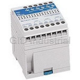
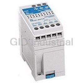
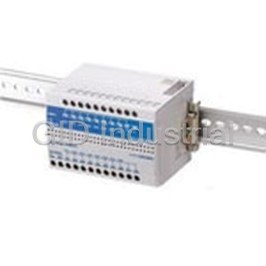
Electromechanical Relay SPST-NO 3A 12VDC 1.2KOhm DIN Rail
EB3C-R02A
Part Number
EB3C-R02A
Price
Request Quote
Manufacturer
IDEC CORPORATION
Lead Time
Request Quote
Category
Relays and I/O Modules » Relay Other
Specifications
Manufacturer
IDEC Corporation
Manufacturers Part #
EB3C-R02A
Industry Aliases
EB3C-R02A
Sub-Category
Other Relays
Factory Pack Quantity
1
Datasheet

Extracted Text
EB3C Barriers Intrinsically Safe: EB3C Discrete Input Barriers Key features: Explosion Protection Discrete Input Barriers: [Exia] II C • IEC60079 compliant • Dry-contact switches can be connected to the EB3C • 8- and 16-circuit types are available in common wiring types, ideal for connection to PLCs (DC voltage only) • Universal AC power voltage (100 to 240V AC) or 24V DC power (UL rating: 100 ~ 120V AC) • No grounding required • IDEC’s original spring-up terminals minimizes wiring time • Installation: 35-mm-wide DIN rail mounting or direct panel mounting FM • Global usage APPROVED LISTED USA: UL/FM Canada: CSA Europe: CE marking, ATEX China: CQST Russia: GOST-R Japan: TIIS Korea: KOSHA • Ship class: NK (Japan), KR (Korea) Dry Contact Switches Dry-contact switches can be connected to the EB3C. LB Series HW Series CW Series Common Wiring for PLC Inputs 8- and 16-circuit types are available in common wiring Spring-up Fingersafe Terminals Reduce types, ideal for connection to PLCs (DC voltage only). Wiring Time Connector Type MIL connector on the non-hazardous side Finger-safe • Easy connection to PLCs • Wiring is cut by 90% (compared with IDEC’s 16-circuit EB3C) • Various 20-pin MIL connectors can be connected www.IDEC.com 224 Barriers Communication Sensors Power Supplies Automation Software PLCs OI Touchscreens OI Touchscreens PLCs Automation Software Power Supplies Sensors Communication Barriers EB3C Barriers Part Numbers Discrete Input Barriers Connection to Number of Power Voltage Non-intrinsically Input Wiring Method Output Part Number Channels Safe Circuit 1 EB3C-R01A 2 EB3C-R02A 3 EB3C-R03A 5 Separate/Common Wiring Compatible EB3C-R05A Relay 6 EB3C-R06A 8 EB3C-R08A 10 EB3C-R10A 8 Common Wiring Only EB3C-R08CA 1 EB3C-T01A 100 to 240V AC 2 EB3C-T02A (UL rating: 100 ~ 120V AC) 3 EB3C-T03A 5 Separate/Common Wiring Compatible Transistor (Sink/Source) EB3C-T05A 6 EB3C-T06A 8 EB3C-T08A 10 EB3C-T10A 8 EB3C-T08CKA* Sink 16 EB3C-T16CKA* Common Wiring Only Transistor 8 EB3C-T08CSA Source 16 EB3C-T16CSA 1 Screw Terminal EB3C-R01D 2 EB3C-R02D 3 EB3C-R03D 5 Separate/Common Wiring Compatible EB3C-R05D 6 Relay EB3C-R06D 8 EB3C-R08D 10 EB3C-R10D 8 EB3C-R08CD Common Wiring Only 16 EB3C-R16CD 1 EB3C-T01D 2 EB3C-T02D 24V DC 3 EB3C-T03D 5 Separate/Common Wiring Compatible Transistor (Sink/Source) EB3C-T05D 6 EB3C-T06D 8 EB3C-T08D 10 EB3C-T10D 8 EB3C-T08CKD* Sink 16 EB3C-T16CKD* Common Wiring Only 8 EB3C-T08CSD Transistor Source 16 EB3C-T16CSD Sink EB3C-T16CKD-C* 16 Connector Wiring Source EB3C-T16CSD-C *Note: These models are NOT Listed by UL Accessories Item Part Number Description BAP1000 Steel (1m long, 7.5mm high) DIN Rail BNDN1000 Aluminum (1m long, 10.5mm high) End Clip BNL6 Medium DIN rail end clip 800-262-IDEC (4332) • USA & Canada 225 EB3C Barriers Specifications Explosion-Protection and Electrical Specifications General Specifications Explosion Protection See Certification Numbers table below AC DC Degree of Protection IP20 (IEC60529) 100 to 240V AC Rated Voltage 24V DC (UL rating: 100 ~ 120V AC) Safe indoor place 85 to 264V AC Discrete Input Barrier Allowable Voltage Range 21.6 to 26.4V DC (non-hazardous area) (UL rating: 85 ~ 125V AC) 50/60 Hz (allowable range: Rated Frequency — Non-intrinsically Safe Circuit 250V AC 50/60Hz, 250V DC 47 to 63 Hz) Maximum Voltage (Um) 125V AC 50/60Hz, 125V DC (UL rating) 10A (100V AC) Inrush Current 10A 1-channel 20A (200V AC) 16-channel Wiring Method Separate Common Wiring Between intrinsically safe circuit and non-intrinsi- Wiring cally safe circuit: 1500V AC Rated Operating Voltage 12V DC ±10% Dielectric Strength Between AC power and output terminal: 1500V AC (1 minute, 1 mA) Rated Operating Current 10 mA DC ±20% Between DC power and transistor output terminal: Maximum Output Voltage (Uo) 13.2V DC 1000V AC Maximum Output Current (lo) 14.2 mA 227.2 mA Operating Temperature –20 to +60°C (no freezing) Maximum Output Power (Po) 46.9 mW 750 mW Storage Temperature –20 to +60°C (no freezing) Maximum External Inductance (Lo)* 175 (125) mH 0.68 (0.68) mH Operating Humidity 45 to 85% RH (no condensation) Maximum External Capacitance (Co)* 900 (740) nF Atmosphere 800 to 1100 hPa 600/(n+1)Ω Pollution Degree 2 (IEC60664) Allowable Wiring Resistance (Rw) 300Ω (n = number of common channels) 10 MΩ minimum (500V DC megger, between the Insulation Resistance same poles as the dielectric strength) Maximum Channels per Common Line – 16 Contact Configuration 1NO Panel mounting: 10 to 55 Hz, amplitude 0.75 mm Damage Limits Rated Insulation Voltage (Ui) 250V AC (UL rating: 125V AC), 125V DC DIN rail mounting: 10 to 55 Hz, amplitude 0.35 mm Vibration Thermal Current (lth) 3A (common terminal: 8A) Resistance Panel mounting: 10 to 55 Hz, amplitude 0.5 mm Operation Extremes Resistive Load AC: 750 VA, DC: 72W (relay output only) Contact DIN rail mounting: 10 to 55 Hz, amplitude 0.35 mm Allowable AC: 750 VA (cos ø = 0.3 to 0.4) 2 Panel mounting: 500 m/s (3 times each on X, Y, Z) Inductive Load Shock Power DC: 48W (L/R = 7 ms) Damage Limits Resistance 2 DIN rail mounting: 300 m/s (3 times each on X, Y, Z) Resistive Load 250V AC 3A, 24V DC 3A Terminal Style M3 screw terminal Rated Load 250V AC 3A (cos ø = 0.3 to 0.4) Inductive Load 24V DC 2A (L/R = 7 ms) Mounting 35-mm-wide DIN rail or panel mounting (M4 screw) Minimum Applicable Load 0.1V DC, 0.1 mA (reference value) 9.6 VA (EB3C-R10A at 200V AC) Power Consumption (approx.) 4.8 W (EB3C-R16CD at 24V DC) Contact Resistance 50 mΩ Weight (approx.) 390g (EB3C-R16CD) ON Time 12 ms maximum (rated voltage) OFF Time 10 ms maximum (rated voltage) Certification Numbers 20,000,000 operations minimum (at Mechanical Life 18,000 operations/hour, without load) Certification Certification Explosion Protection Organization Number 100,000 operations minimum Electrical Life (at 1,800 operations/hour, rated load) Class I, II, III Div. 1 3015417 Groups A, B, C, D, E, F and G Short-circuit Protection None UL/FM UL file: E234997 Class I, Zone 0 AEx [ia] IIC Rated Voltage 24V DC Maximum Voltage 30V DC CSA Class I Div. 1 Groups A, B, C, D 166730 Maximum Current 100 mA (connector type: 15 mA) NEMKO [Exia] II C Nemko 02ATEX279 Leakage Current 0.1 mA maximum TIIS Japan Relay barrier: [Exia] II C TC15753 Voltage Drop 1V maximum Class NK [Exia] II C 02T606 Clamping Voltage 33V (1W) GOST-R [Exia] II C Inrush Current 0.5A maximum (1 sec) KOSHA [Exia] II C 11-AV4BO-0457 ON Time 0.1 ms maximum (resistive load) CQST [Exia] II C CNEx10.2445 OFF Time 0.4 ms (typical) (resistive load) Class NK is Japan Shipping agency approval, Class KR is Korean shipping agency approval. Short-circuit Protection None Values in ( ) are those approved by TIIS (Technology Institution of Industrial Safety, Japan). Note: Um = 125V AC for UL ratings www.IDEC.com 226 Barriers Communication Sensors Power Supplies Automation Software PLCs OI Touchscreens Installation Non-intrinsically Safe Circuits Intrinsically Safe Circuits Location Transistor Output Relay Output OI Touchscreens PLCs Automation Software Power Supplies Sensors Communication Barriers EB3C Barriers Circuit Diagrams Internal Circuit Block Diagrams AC Power, Relay Output Type DC Power, Transistor Output Type Connector Wiring, Sink Output Type Hazardous Area •••••••• P1 N1 P2 N2 P3 N3 P1 • • •• P16 N1 N2 P1 N1 P2 N2 P3 N3 Non-hazardous Area Yellow Yellow Yellow Yellow Yellow Yellow Yellow Yellow Green Green Green ~ ~ ~ ~ ~ ~ ~ + – A1 C1 A2 C2 A3 C3 + – A1 • • •• A16 C1 C2 L N A1 C1 A2 C2 A3 C3 Wiring Examples External Wiring Examples Transistor Sink Output Type (Ex.: EB3C-T08CKD) Transistor Source Output Type (Ex.: EB3C-T08CSD) P1 P2 P3 P4 P5 P6 P7 P8 N1 N2 + – A1 A2 A3 A4 A5 A6 A7 A8 C1 C2 Load Power 24V DC 24V DC Relay Output Type (Ex.: EB3C-R06A) Transistor Output Type (Ex.: EB3C-T06A) P1 N1 P2 N2 P3 N3 P4 N4 P5 N5 P6 N6 P1 N1 P2 N2 P3 N3 P4 N4 P5 N5 P6 N6 L N A1 C1 A2 C2 A3 C3 A4 C4 A5 C5 A6 C6 L N A1 C1 A2 C2 A3 C3 A4 C4 A5 C5 A6 C6 Load Power AC Power AC Power Load AC/DC Power 24V DC 800-262-IDEC (4332) • USA & Canada 227 Load Load Load Load Load Load Load Load Load Load Load Load Load Load Load Load Load Load Load Load EB3C Barriers Dimensions (mm) EB3C–*08 EB3C–*05 EB3C–*10 EB3C–*02 EB3C–*06 EB3C–*16C EB3C–*03 EB3C–*01 EB3C–*08C 42 65 110.5 171.5 77.5 ø6 hole 10 10 10 10 10 Mounting Hole Layout (Screw Mounting) 2-M4 tapped or 2-M4 tapped or 2-M4 tapped or 4-M4 tapped or 2-ø4.5 mounting 2-ø4.5 mounting holes 2-ø4.5 mounting holes 4-ø4.5 mounting holes holes 28 51 97 97 Connector Applicable Crimping Terminal ø3.2 min. EB3C–T16C -C 171.5 3 max. 5.4 min. 4-M4 or 4-ø4.5 holes Stripping the Wire End Solid Wire 83.5 97 6 to 8 mm Mounting Hole Layout Stranded Wire (Ferrule) 6 to 8 mm 10 10 97 www.IDEC.com 228 ø6 Barriers Communication Sensors Power Supplies Automation Software PLCs OI Touchscreens 77.5 (4) 75 6 6 65 4 61 77.5 75 4- ø4.5 holes 65 65 65 6 max. (4) ø4.4 65 General Information Barriers General Information What is Explosion Protection? Explosion Mechanism For an explosion to occur, both hazardous atmosphere (mixture of explosive gas/vapor and air) and ignition source from electrical equipment must exist. The first step for explosion prevention is to prevent the three factors (explosive gas/vapor, air, and ignition source) from existing at the same time. Air Ignition Explosive Explosion + + (oxygen) Source Gas/Vapor Ignition source: Electrical equipment which originates electrical sparks or has a high temperature, capable of causing ignition in a hazardous atmosphere. Explosion protection types: 1. Separation of explosive gas/vapor and ignition source Flameproof explosion protection Pressurized explosion protection 2. Low power on ignition source Intrinsically safe explosion protection Classification of Hazardous Areas • Required when selecting explosion protection electrical equipment and wiring methods. • Determined by user. • Hazardous areas are classified depending on the frequency of the occurrence of hazardous atmosphere. IEC Classification Zone 0: Where hazardous atmosphere may exist for 1,000 hours or longer per year. Zone 1: Where hazardous atmosphere may exist for 10 to 1,000 hours per year. Zone 2: Where hazardous atmosphere may exist for less than 1 hour per year. Gasoline Tank Example Zone 0 Zone 1 Zone 2 Oil Containment Wall Gasoline www.IDEC.com 248 Barriers Communication Sensors Power Supplies Automation Software PLCs OI Touchscreens OI Touchscreens PLCs Automation Software Power Supplies Sensors Communication Barriers General Information Barriers Explosion Protection Types Intrinsically Safe Structure • Structure in which voltage and current are limited so that no sparks, arc, and thermal effect produced by electric equipment (switch, pilot light, etc) in hazardous areas are capable of causing ignition of explosive gas/vapor. Hazardous Area Non-hazardous Area Barrier Switch, pilot light, sensor, thermocouple buzzer, etc. Power Supply Type of connectable equipment depends on the barrier type. Wiring distance is limited by wiring capacitance and inductance. Features: • Barrier is installed in non-hazardous area, and is connected to the switches or pilot lights in hazardous area. • The intrinsically safe system can be used in zone 0. • Because voltage and current to the electric equipment are limited, the variety of devices that can be connected to the barrier is restricted. • Wiring is required between hazardous and non-hazardous areas. • Grounding (grounding resistance 10Ω max.) may be required (EB3C, EB3L do not require grounding). Grounding - The procedure to achieve required resistance value by inserting a grounding wire into a hole in the ground and furnishing the surrounding with material of superior electrical conductivity. Non-insulated barrier (Zener barrier): grounding resistance 10Ω max. • While the voltage difference between the circuits is limited in Zener barriers, the voltage difference between the circuits and grounding is unlimited. When a short-circuit occurs between the circuits and ground, high voltage/current may be generated in the circuits, causing a possible explosion. The 0V line of circuits, therefore, must be provided with grounding (resistance 10Ω max.) so that the voltage/current can be shunted to the ground. Insulated barrier: grounding resistance 100Ω max. • Intrinsically safe and non-intrinsically safe parts are electrically isolated by an isolation transformer. If a sufficient isolation distance is not provided on the isola- tion transformer, however, the transformer may short-circuit between primary and secondary when an abnormal voltage occurs. This may generate high voltage/ current in the intrinsically safe circuit, causing a possible explosion. A transformer with metallic isolator must be used between primary and secondary, and grounding (resistance 100Ω max.) must be provided. Difference between NI (Non-incendive) & IS (Intrinsic Safety) Standard Zone 0 Zone 1 Zone 2 Non-hazardous • NI: Installed in areas that are Zone 2 hazardous locations. NI Devices • IS: Installed in areas that are non-hazardous. Only Zone connected with NI or IS Advantages & Disadvantages • NI: Small and inexpensive. Devices connected with NI are also installed only in the Zone 2 area. • IS: Small but more expensive. Devices connected IS with IS can be used in the Zone 0, 1 and 2 areas (all zones). All Zones 800-262-IDEC (4332) • USA & Canada 249 General Information Barriers Structure NI Structure resistance resistance When the zener is broken, the When the zener is broken, the voltage cannot be limited: high voltage cannot be limited: high Zener voltage is applied to the connecting Zener voltage is applied to the connecting device side, which could lead to device side, which could lead to (for Voltage (for Voltage explosion. explosion. Limitation) Limitation) IS Structure The fuse is for current limitation The fuse is for current limitation resistance resistance fuse fuse These 3 zeners make redundant These 3 zeners make redundant protection (voltage) protection (voltage) Note : Instead of zeners, thyristors are used in EB3C for better energy effeciency. Explosion Protection Marking Gas is categorized into groups by explosiveness and ignition temperature. Technical standard: Determines the gas type which can be used with the apparatus. Ex ia IIC T6 Temperature: maximum surface temperature of electrical equipment T1: 450°C T2: 300°C T3: 200°C T4: 135°C T5: 100°C T6: 85°C Electrical Equipment: IIA: Applicable to group IIA gas IIB: Applicable to groups IIA and IIB gasses IIC: Applicable to groups IIA, IIB, and IIC gasses Explosion Protection: d: Flameproof type e: Increased safety type p: Pressurized type ia, ib: Intrinsic safety type de: Flameproof and increased safety type d(ia): Intrinsic safety and flameproof type Shows compliance with the standard Examples: ExdeIIBT4, EXeIICT4, ExpIIBT4, ExiaIICT5 www.IDEC.com 250 Barriers Communication Sensors Power Supplies Automation Software PLCs OI Touchscreens OI Touchscreens PLCs Automation Software Power Supplies Sensors Communication Barriers General Information Barriers EB3C/EB3L Features Small and lightweight EB3C Weight: 380g • Plastic housing (10-circuit) Dimensions: 171.5 L × 75 W × 77.5 H (mm) EB3L Weight: 360g • Small system design (10-circuit) Dimensions: 171.5 L × 75 W × 77.5 H (mm) No grounding required: less labor, less cost No explosion protection grounding. Isolation transformer is used. All isolations – not only between primary and secondary, but also cores and bobbins – are reinforced. No isolator = No grounding No electrical equipment grounding. Power supply part: Electric shock is prevented with reinforced isolation. Conforms to IEC standard. Output part: The small power & EMC design requires no grounding. Conforms to IEC switch output standard. Shield wire treatment Shield wires of intrinsically safe circuits are grounded to the panel in non-hazardous area, and not connected to the N terminal on the barrier. Common Type and Connector Type 1. Common type For 8 and 16 circuits. Easy connection to PLC. 2. Connector type • Flat cable connection between non-intrinsically safe part and PLC. • Connectable to IDEC’s FC5A, FC4A and Mitsubishi’s AIS. 800-262-IDEC (4332) • USA & Canada 251 General Information Barriers Standards Less labor 1. CE 1. Finger-safe spring-up terminal Conforms to EMC directive and LVD. The finger-safe, captive spring-up terminals prevent electric shock (IP20), and EMC directive: make installation easy. No screw loss. Electromagnetism generated by the barrier does not affect other communica- 2. Universal voltage tion equipment. Also, electromagnetism generated by other communication 100 to 240V AC (UL rating 100 ~ 120VAC). equipment does not affect the barrier. LVD (Low Voltage Directive): 3. Installation For rated voltages 50 to 1000V AC, 75 to 1500V DC. Direct and DIN-rail mountable. 2. ATEX EB3 series: Screws cannot be touched by fingers even when loosened. Adopted by EU, this directive covers electrical and mechanical equipment and protective systems, which may be used in potentially explosive atmospheres Switches connectable to EB3C (Europe). EN50014 series is adopted. Switches which are configured only with mechanical contacts (dry contacts) can 3. FM (Factory Mutual Approval) be connected to the EB3C. A private US certification organization for waterproof and intrinsic safety. Widely recognized for more intrinsic safety than UL. Pushbutton, selector, cam, toggle, limit, micro, reed, foot, pressure, and tempera- ture switches can be used. 4. CSA (Canadian Standards Association) Note: Contact rating must be 13.2V, 14.2 mA minimum. Contact material such as silver oxide A Canadian certification organization for electrical equipment. cadmium and silver tungsten may cause conduction failure at 10 mA due to the film gener- ated on the surface. 5. NK: Class NK (Nippon Kaiji Kyokai) Required for ships with Japanese ship registration. 6. Underwriters Laboratories (UL) - A US certification agency for all electrical and hazardous location products. Equipment connectable to EB3L Common wiring: Only EB3P-L type pilot lights, which have been approved, can be connected to the EB3L discrete output barrier. Separate wiring: No approval is required for pilot lights and buzzers to be connected to the EB3L discrete output barrier. However, users must make sure that the temperature rise of the equipment is below the rated value with the current and voltage supplied from the discrete input barrier. Also take the ratings of intrinsically safe circuit into consideration. IDEC’s EB3P-L type pilot light lights and EB3P-Z type buzzers satisfy the ratings. EB3P-L Pilot light: ø22 and ø30, a total of 78 types • Super LED installed ø30: APN, UPQN equivalent • Lens colors: amber, blue, green, red, white, and yellow ø22: APW, HW,LW,UPQW equivalent • Accessories and maintenance parts are the same as standard control units. See IDEC’s control units catalogs. IPL1 Miniature pilot light: ø6, ø8, and ø10, a total of 40 types • Low price • Illumination colors: amber, green, red, white, and yellow EB3P-Z buzzer: Continuous and intermittent sound, ø30 mounting hole, terminal block type When connecting one buzzer and 15 pilot lights to EB3L-S16CSD, do not • Degree of protection: IP20 connect the negative lines of buzzer and pilot lights in common. Connect • Common wiring is not available due to high inductance value. the buzzer and pilot lights to the barrier using separate lines (15 pilot • Approved by TIIS only lights can be wired with one common line). www.IDEC.com 252 Barriers Communication Sensors Power Supplies Automation Software PLCs OI Touchscreens OI Touchscreens PLCs Automation Software Power Supplies Sensors Communication Barriers General Information Barriers Connecting Illuminated Switches Made possible with the combination of EB3L and EB3C. User benefits • Flexibility of control panel design Explosion protected panels can be designed in a similar manner to non-explosion protected panels (non-explosion protected panels can be used as explosion protected panels without any changes). • Control panel becomes smaller. Connectable illuminated switch: 134 types ø30: ALN2 equivalent EB3P-LB Illuminated Pushbutton Switch { ø22: ALW2, HW, LW equivalent ø30: ASLN equivalent EB3P-LS Illuminated Selector Switch { ø22: ASLW, HW, LW equivalent Super LED installed. Lens color: amber, blue, green, red, white, yellow Connection Method 1. Difference between EB3C and EB3L EB3C: ON/OFF output signals to other equipment. Connection to PLC’s inputs. EB3L: ON/OFF input signals to pilot lights and buzzers. Connection from PLC’s outputs. 2. Sink and Source Available combination: Sink Output + Source Input or Source Output + Sink Input. Sink output (source input) is mainly adopted in Japan (Europe: source output). Other information • Up to 16 channels, including both pilot lights and contacts, can be connected in common wiring. • Connect the common wires of pilot lights and contacts separately to the N terminals of each barrier. • Use two wires to connect the common terminals (N terminals) EB3C and EB3L barriers. • Accessories and maintenance parts are the same as the standard control units. See IDEC’s control units catalogs for details. Safety Precautions Electrostatic protection: Prevention of fire ignition and explosion caused by electrostatic charges. • As required by IEC60079-11, limit the exposed surface of plastic equipment (switch, pilot light) installed in hazardous areas. 2 • 20 cm max. for IIC gas atmosphere. 2 • 100 cm max. for IIB and IIA gas atmosphere. • When the surface area of other than operating parts exceeds the limit, attach a caution plate. • Pushbutton, knob, or other parts which are frequently touched by operators. EB3C Separate and Common Types 1. Separate Wiring Type The output circuit is isolated for each channel. Both sink and source outputs can be connected. 2. Common Wiring Type The output circuit is not isolated from each other and uses common terminal C. Sink and source outputs are available on different modules. 800-262-IDEC (4332) • USA & Canada 253 General Information Barriers Sink/Source Definition Source Output Sink Output 24V PLC PLC EB3C-T16 24V EB3C-T16 CSD CKD C COM I0 A1 A1 I0 A2 I1 A2 I1 C COM Source GND GND Sink Input Input PNP N PN Open Collector Open Collector Output Output 24V I3 I3 GND Source Input Sink Input EB3L-S16 EB3L-S16 CSD CKD S1 Q0 24V COM 24V C Sink Source S2 Q1 S1 Q0 Output Output C COM S2 Q1 GND Source Output = PNP Output = Positive Common Wiring Sink Output = NPN Output = Negative Common Wiring Sink Input Source Input Relay Terminal Block Noise Countermeasure • The LED connected to the EB3L may blink due to noises. When connecting a discrete input barrier to the switches and pilot lights • Check the wiring so that noise is not imposed on the EB3L (eg. separation installed in hazardous area, use a relay terminal block. from power line). • Noise can be avoided also by inserting a noise filter for AC line into the barrier’s power input part. A relay terminal block can be eliminated when using EB3C and EB3L, as these Recommended noise filters: barriers are considered as relay terminal blocks. DENSEI-LAMBDA TDK Schaffner MBW-1202-22 PBF-1202-22 ZCB2203-11 FN670-3/06 Cable Extension and Intrinsic Safety Parameter MBW-1203-22 PBF-1203-22 ZCB2206-11 • For wiring between the barrier and the switches and pilot lights installed in MBW-1206-22 PBF-1206-22 2 hazardous area, use a cable of 2.0 mm . The cable can be extended up to approximately 1 km. 2 • For EB3L of common wiring type, use a cable of 2.0 mm . The cable can be extended up to approximately 600 m. Longer cables cause dim LED lighting. Make sure that wiring parameters (inductance, capacitance, resistance) do not exceed the maximum limit. www.IDEC.com 254 Barriers Communication Sensors Power Supplies Automation Software PLCs OI Touchscreens
Frequently asked questions
How does Electronics Finder differ from its competitors?

Is there a warranty for the EB3C-R02A?
Which carrier will Electronics Finder use to ship my parts?
Can I buy parts from Electronics Finder if I am outside the USA?
Which payment methods does Electronics Finder accept?
Why buy from GID?

Quality
We are industry veterans who take pride in our work

Protection
Avoid the dangers of risky trading in the gray market

Access
Our network of suppliers is ready and at your disposal

Savings
Maintain legacy systems to prevent costly downtime

Speed
Time is of the essence, and we are respectful of yours
Related Products
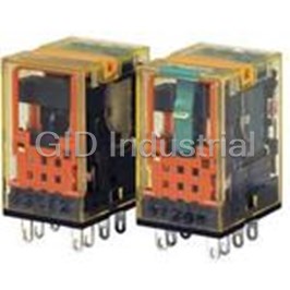
Electromechanical Relay 220/240VAC 18.23KOhm 10A DPDT(27.5x21x41.6)mm Socket General Purpose Relay A...
Electromechanical Relay 100 to 240VAC 3A SPST-NO(42x75x77.5)mm DIN Rail Relay Barrier EB3C-R01A
Electromechanical Relay SPST-NO 3A 12VDC 1.2KOhm DIN Rail EB3C-R03A
Electromechanical Relay SPST-NO 3A 12VDC 1.2KOhm DIN Rail EB3C-R05A
Electromechanical Relay SPST-NO 3A 12VDC 1.2KOhm DIN Rail EB3C-R08A
Electromechanical Relay 12VDC 1.2KOhm 3A SPST-NO(171.5x75x77.5)mm DIN Rail Relay Barrier EB3C-R10A
Request a Quote

The quote request has been received
Close

Facing challenges or have inquiries? Feel free to contact us!
Call Us +1-469-283-2440
What they say about us
FANTASTIC RESOURCE
One of our top priorities is maintaining our business with precision, and we are constantly looking for affiliates that can help us achieve our goal. With the aid of GID Industrial, our obsolete product management has never been more efficient. They have been a great resource to our company, and have quickly become a go-to supplier on our list!
Bucher Emhart Glass
EXCELLENT SERVICE
With our strict fundamentals and high expectations, we were surprised when we came across GID Industrial and their competitive pricing. When we approached them with our issue, they were incredibly confident in being able to provide us with a seamless solution at the best price for us. GID Industrial quickly understood our needs and provided us with excellent service, as well as fully tested product to ensure what we received would be the right fit for our company.
Fuji
HARD TO FIND A BETTER PROVIDER
Our company provides services to aid in the manufacture of technological products, such as semiconductors and flat panel displays, and often searching for distributors of obsolete product we require can waste time and money. Finding GID Industrial proved to be a great asset to our company, with cost effective solutions and superior knowledge on all of their materials, it’d be hard to find a better provider of obsolete or hard to find products.
Applied Materials
CONSISTENTLY DELIVERS QUALITY SOLUTIONS
Over the years, the equipment used in our company becomes discontinued, but they’re still of great use to us and our customers. Once these products are no longer available through the manufacturer, finding a reliable, quick supplier is a necessity, and luckily for us, GID Industrial has provided the most trustworthy, quality solutions to our obsolete component needs.
Nidec Vamco
TERRIFIC RESOURCE
This company has been a terrific help to us (I work for Trican Well Service) in sourcing the Micron Ram Memory we needed for our Siemens computers. Great service! And great pricing! I know when the product is shipping and when it will arrive, all the way through the ordering process.
Trican Well Service
GO TO SOURCE
When I can't find an obsolete part, I first call GID and they'll come up with my parts every time. Great customer service and follow up as well. Scott emails me from time to time to touch base and see if we're having trouble finding something.....which is often with our 25 yr old equipment.
ConAgra Foods