IDEC CORPORATION FC4A-AS62M
Specifications
Manufacturer
IDEC Corporation
Manufacturers Part #
FC4A-AS62M
Sub-Category
Specialized Semicondutor Interfaces
Factory Pack Quantity
1
Datasheet
Extracted Text
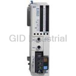
Communication & Networking PLCs Operator Interfaces Automation Software Power Supplies Sensors AS-Interface Communication & Networking MicroSmart AS-Interface Master Module Capable of Connecting 62 Slaves • Compliance with AS-Interface Ver. 2.1 specifi cations • Digital and analog slaves can be connected. • Confi guration and slave monitoring can be done using LED indicators and pushbuttons on the front panel as well as using WindLDR. • Analog signals can also be processed using built-in analog voltage input terminal or optional analog I/O modules. • IEC62026-2 compliant. Part Numbers AS-Interface Master Module Programming and Monitoring Software Part Number Part Number FC4A-AS62M WindLDR FC9Y-LP2CDW MicroSmart Pentra CPU All-In-One Type Part Number Power I/O Points Input Output Expandability FC5A-C24R2C24V DC 88 maximum I/O (up to 24 (14 in/10 out) 24V DC (Sink/Source) Relay 4 expansion modules) FC5A-C24R2 100-240V AC Slim Type Part Number Power I/O Points Input Output Expandability 6 Relays FC5A-D16RK1 2 Transistor Sink 496 24V DC 16 (8 in/8 out) 24V DC (Sink/Source) (up to 15 expansion modules) 6 Relays FC5A-D16RS1 2 Transistor Source FC5A-D32K3 Transistor Sink 512 24V DC 32 (16 in/16 out) 24V DC (Sink/Source) (up to 15 expansion modules) FC5A-D32S3 Transistor Source USA: 800-262-IDEC Canada: 888-317-IDEC 247 AS-Interface Communication & Networking MicroSmart Slim CPU Part Number Power I/O Points Input Output Expandability 6 Relays FC4A-D20RK1 244 2 Transistor Sink 20 (12 in/8 out) (up to 7 expansion modules) 6 Relays 24V DC FC4A-D20RS1 24V DC 2 Transistor Source (Sink/Source) FC4A-D40K3 Transistor Sink 264 40 (24 in/16 out) (up to 7 expansion modules) FC4A-D40S3 Transistor Source Accessories Description Part Number Terminal Block for AS-Interface Master Module 3-pole FC4A-PMT3 248 www.idec.com Communication & Networking Sensors Power Supplies Automation Software Operator Interfaces PLCs Communication & Networking PLCs Operator Interfaces Automation Software Power Supplies Sensors AS-Interface Communication & Networking Specifi cations (AS-Interface Master Module) General Specifi cations Operating Temperature 0 to 55°C (no freezing) Storage Temperature –25 to +70°C (no freezing) Relative Humidity Level RH1, 30 to 90% (non-condensing) Pollution Degree 2 (IEC60664) Degree or Protection IP20 Corrosion Immunity Atmosphere free from corrosive gases Altitude Operation: 0 to 2000m Transport: 0 to 3000m Vibration Resistance • When mounted on a DIN rail: 2 10 to 57 Hz amplitude 0.075mm, 57 to 150 Hz acceleration 9.8 m/s (1G) 2 hours per axis on each of three mutually perpendicular axes When mounted on a panel surface: • 2 2 to 25 Hz amplitude 1.6mm, 25 to 100 Hz acceleration 39.2 m/s (4G) 90 minutes per axis on each of three mutually perpendicular axes 2 Shock Resistance 147 m/s (15g), 11ms duration, 3 shocks on each of three mutually perpendicular axes (IEC61131) Functional Specifi cations External Power Supply AS-Interface power supply, 29.5 to 31.6V DC AS-Interface 65mA (normal operation) Current 110mA maximum Effect of Improper Input Connection No damage MSTB2.5/3-GF-5.08BK (Phoenix Contact) Connector on Mother Board Insertion/removal durability: 100 times minimum Internal Current 80mA (5V DC) AS-Interface Master Module Power Consumption 540mW (24V DC) Weight (approx.) 85g Communication Specifi cations When 1 through 19 slaves are connected: 3ms When 20 through 62 slaves are connected: 0.156 x (1 + N) ms, where N is the number of active slaves Maximum Bus Cycle 5ms maximum when 31 slaves are connected 10ms maximum when 62 slaves are connected Standard slaves: 31 Maximum Slaves A/B slaves: 62 Standard slaves: 248 total (124 inputs + 124 outputs) Maximum I/O Points A/B slaves: 434 total (248 inputs + 186 outputs) When using no repeater or extender: 100m AS-Interface Cable Maximum Length When using a total of 2 repeaters or extenders: 300m Rated Bus Voltage 30V DC Dimensions FC4A-AS62M 9.9 23.5 9.4 70 All dimensions in mm. USA: 800-262-IDEC Canada: 888-317-IDEC 249 17.7 37.5 10 90 AS-Interface Communication & Networking Installation Location • MicroSmart modules must be installed correctly for optimum performance. • MicroSmart is designed for installation in a cabinet. Do not install the MicroSmart outside a cabinet. • The environment for using the MicroSmart is “Pollution degree 2.” Use the MicroSmart in environments of pollution degree 2 (according to IEC60664-1). • Make sure that the operating temperature does not drop below 0ºC or exceed 55ºC. If the temperature does exceed 55ºC, use a fan or cooler. • Mount the MicroSmart on a vertical plane as shown at right. • To eliminate excessive temperature build-up, provide ample ventilation. Do not install the MicroSmart near, and especially above, any device which generates considerable heat, such as a heater, transformer, or large-capacity resistor. Relative humidity should be above 30% and below 95%. End Clip • MicroSmart should not be exposed to excessive dust, dirt, salt, direct sunlight, vibrations, or shocks. BNL-6 Do not use the MicroSmart in an area where corrosive chemicals or fl ammable gases are present. The modules should not be exposed to chemical, oil, or water splashes. Cable Connection Caution: • Make sure that operating conditions are within the specifi cation values. • Connect ground terminal of the CPU module to a proper ground, otherwise electric shock may occur. • Do not touch live terminals, otherwise electric shock may occur. • Applicable ferrules, crimping tool and screwdriver are listed below. • When connecting stranded wire or multiple wires to a screw terminal block, use a ferrule. Ferrules for Terminal Block Crimping Tool 2 Cross-section 0.5mm (20AWG) CRIMPFOX ZA 3 (Phoenix Contact) For 1-cable connection: AI 0.5-8 WH For 2-cable connection: AI-TWIN 2 x 0.5-8 WH Screwdriver 2 Cross-section 0.75mm (18AWG) SZS 0.6x3.5 (Phoenix Contact) For 1-cable connection: AI 0.75-8 WH For 2-cable connection: AI-TWIN 2 x 0.75-8 GY Screw Tightening Torque 2 Cross-section 1.5mm (16AWG) AS-Interface connector terminal screws: 0.5 to 0.6 N•m For 1-cable connection: AI 1,5-8 BK AS-Interface connector mounting screws: 0.3 to 0.5 N•m Recommended ferrules shown above are made by Phoenix Contact. AS-Interface Cable Wiring Insert the terminal block to the connector on the AS-Interface master module, and Before wiring the AS-Interface cable, remove the AS-Interface cable terminal tighten the mounting screws to a torque of 0.3 to 0.5 N•m. block from the AS-Interface cable connector on the AS-Interface master module. AS-Interface specifi es use of brown cables for the AS-Interface + line, and blue cables for the AS-Interface – line. Connect the cables according the colors indi- cated on the terminal block. Tighten the terminal screws to a torque of 0.5 to 0.6 N•m (Replacement terminal block: FC4A-PMT3PN02, package quantity: 2) Use a ferrule. Brown Label Brown AS-i– Blue Label Blue AS-i– Use a ferrule. 250 www.idec.com Communication & Networking Sensors Power Supplies Automation Software Operator Interfaces PLCs Communication & Networking PLCs Operator Interfaces Automation Software Power Supplies Sensors AS-Interface Communication & Networking PS2R AS-Interface Power Supply AS-Interface Power Supply with Universal AC Input Voltage • Input voltage range: 100 to 240V AC • Two output ratings: 73W and 145W • Slim housing style mountable on DIN rails • IP20 fi nger-safe terminals • CE marked (LVD, EMCD) • UL listed (UL 508), CSA (C22.2 No. 950), TÜV (EN60950, EN61010-1) • Noise standards EN55022, EN61000-6-2 compliant • Input indicator (orange) and output indicator (green) • IEC62026-2 compliant Part Numbers AS-Interface Power Supply Output Capacity Input Voltage Output Voltage Part Numbers 73W PS2R-Q30ABL 100 to 240V AC 30.5V DC 145W PS2R-F30ABL USA: 800-262-IDEC Canada: 888-317-IDEC 251 AS-Interface Communication & Networking Specifi cations Model PS2R-Q30ABL PS2R-F30ABL Effi ciency 83% (typical) at the rated input/output Voltage 100 to 240V AC (85 to 264V AC) Frequency 47 to 63 Hz Input 100V AC 1.8A (typical) at the rated load 3.0A (typical) at the rated load Current 220V AC 1.0A (typical) at the rated load 2.0A (typical) at the rated load Leakage Current 3.5mA maximum (UL, CSA, VDE) Inrush Current 30A maximum (25°C at cold start) Rated Voltage 30.5V DC Rated Current 2.4A 4.8A Adjustable Voltage Range N/A Ripple Noise Voltage 300mV p-p maximum (0 to 10 kHz), 50mV p-p maximum (10 to 500 kHz) according to AS-Interface standard Output Input/Load Fluctuation 3% Overall Fluctuation 29.5 to 31.6V DC including input fl uctuation, output fl uctuation, temperature fl uctuation and ripple voltage Delay Time 2 sec maximum (delay in output voltage change from 5V to 26.5V) according to AS-Interface standard Startup Time 1 sec maximum (output voltage change from 21.5V to 29.5V) according to AS-Interface standard Output Holding Time 10ms minimum at 85V AC, rated load 1 Overcurrent Protection 110% (typical), automatic reset 2 Overvoltage Protection 120% minimum Supplementary Undervoltage Protection 95% maximum, automatic reset Functions Input Indicator Orange Output Indicator Green Between inputs and outputs: 3.0 kV AC, 1 minute Dielectric Strength Between inputs and ground: 3.0 kV AC, 1 minute Between outputs and ground: 0.5 kV AC, 1 minute Between inputs and outputs: 100 MΩ minimum (500V DC megger) Insulation Resistance Between inputs andground: 100 MΩ minimum (500V DC megger) Operating Temperature 0 to 60°C (See the derating curve.) Vertical mounting only Storage Temperature –25 to +70°C (no freezing, non-condensation) Operating Humidity 95% RH (non-condensation) 2 10 to 57 Hz amplitude 0.075mm, 57 to 150 Hz acceleration 10 m/s (1G) Vibration Resistance 10 cycles per axis on each of three mutually perpendicular axes 2 Shock Resistance 147 m/s (15G), 11ms duration, 2 shocks per axis, on six mutually perpendicular axes Terminal IP20 Weight (approx.) 800g 1300g Dimensions 120H x 54W x 120D mm 120H x 81W x 120D mm UL 508 listed Safety Standards CSA C22.2 No. 950 EN60950, EN61010 AS-Interface Standard EN50295 (EMI) IEC61000-6-2 EMC Radiated Emission EN55022 class B Conducted Emission EN55022 class B 1. The AS-Interface power supply is provided with an overvoltage protection circuit, but a long period of overload and short-circuit should be avoided. 2. After turning off the input voltage, allow more than 10 seconds before turning on again. 252 www.idec.com Communication & Networking Sensors Power Supplies Automation Software Operator Interfaces PLCs Communication & Networking PLCs Operator Interfaces Automation Software Power Supplies Sensors AS-Interface Communication & Networking Block Diagram Output Derating Terminal Names (Operating temperture is the temperature around the power supply) PS2R-Q30ABL j (L) AC input terminal k (N) AC input terminal (ground side) PS2R-F30ABL 100 l ( ) Ground terminal (protective ground) L N 90 m (AS-i+) AS-Interface + output terminal 80 n (AS-i–) AS-Interface – output terminal 70 60 o ( ) Ground terminal (output side) 50 p (~) Input indicator (goes on when AC input is on) 40 q (AS-i) Output indicator (goes on when DC output is on) 30 20 10 lkj lkj 0 0 10 20 30 40 50 60 Operating Temperature (°C) p p q q AS-i GND GND AS-i + AS-i + AS-i – – o o m m n n Dimensions PS2R-Q30ABL PS2R-F30ABL 54 120 120 81 All dimensions in mm. USA: 800-262-IDEC Canada: 888-317-IDEC 253 120 Output Power (%) 120 AS-Interface Communication & Networking Precautions for Installation 1. Heat Dissipation by Convection 3. Mounting on 35mm-wide DIN Rails Keep minimum spacing of 50mm above and below, and 15mm on both sides Mounting to ensure proper ventilation. To mount the power supply on a DIN rail, place the input terminal side up and put the groove of the power supply on the DIN rail as shown. Press the power supply towards the DIN rail. 50 mm Removing Insert a fl at screwdriver into the slot in the clamp. While pulling out the clamp, turn the power supply bottom out. N L INPUT 100-240 VAC j AS-i 15 mm 15 mm m k l 145w PS2R-F30ABL Mounting on DIN Rail Removing from DIN Rail OUTPUT 30.5VDC 4.8A AS-i+ AS-i– AS-i+ AS-i– Mounting Direction The AS-Interface power supply can be mounted on a vertical plane only. Other mounting directions are not allowed because of heat dissipation. 50 mm Over Current Protection When an overcurrent of 110% of the rated output current fl ows due to an overload, the output voltage drops automatically and intermittent operation 2. Applicable Wires, Ferrules and Tightening Torque starts. When the load returns to normal conditions, the normal output voltage is Ferrule Stranded wire automatically restored. Prevent overload or short-circuitry for a long period of Solid wire time, otherwise the internal elements will be damaged. Ferrule/ Overvoltage Protection Wire When the output voltage exceeds 120% the rated output voltage, the output 2 mm 0.14 to 1.5 0.14 to 0.75 0.14 to 2.5 0.14 to 4 0.14 to 1.5 is turned off. When the output voltage is turned off due to an overvoltage, turn the input off, and after more than 10 seconds, turn the input on again. AWG 26 to 16 26 to 18 26 to 14 26 to 12 26 to 16 Undervoltage Protection 0.6 N•m When the output voltage drops below 95% the rated output voltage, the C output is turned off. When the cause of the error is removed, normal output ø3.5mm 5.4 in•lbs voltage is automatically restored. 254 www.idec.com Communication & Networking Sensors Power Supplies Automation Software Operator Interfaces PLCs
Frequently asked questions
How does Electronics Finder differ from its competitors?

Is there a warranty for the FC4A-AS62M?

Which carrier will Electronics Finder use to ship my parts?

Can I buy parts from Electronics Finder if I am outside the USA?

Which payment methods does Electronics Finder accept?

Why buy from GID?

Quality
We are industry veterans who take pride in our work

Protection
Avoid the dangers of risky trading in the gray market

Access
Our network of suppliers is ready and at your disposal

Savings
Maintain legacy systems to prevent costly downtime

Speed
Time is of the essence, and we are respectful of yours


 Manufacturers



What they say about us
FANTASTIC RESOURCE
One of our top priorities is maintaining our business with precision, and we are constantly looking for affiliates that can help us achieve our goal. With the aid of GID Industrial, our obsolete product management has never been more efficient. They have been a great resource to our company, and have quickly become a go-to supplier on our list!
Bucher Emhart Glass
EXCELLENT SERVICE
With our strict fundamentals and high expectations, we were surprised when we came across GID Industrial and their competitive pricing. When we approached them with our issue, they were incredibly confident in being able to provide us with a seamless solution at the best price for us. GID Industrial quickly understood our needs and provided us with excellent service, as well as fully tested product to ensure what we received would be the right fit for our company.
Fuji
HARD TO FIND A BETTER PROVIDER
Our company provides services to aid in the manufacture of technological products, such as semiconductors and flat panel displays, and often searching for distributors of obsolete product we require can waste time and money. Finding GID Industrial proved to be a great asset to our company, with cost effective solutions and superior knowledge on all of their materials, it’d be hard to find a better provider of obsolete or hard to find products.
Applied Materials
CONSISTENTLY DELIVERS QUALITY SOLUTIONS
Over the years, the equipment used in our company becomes discontinued, but they’re still of great use to us and our customers. Once these products are no longer available through the manufacturer, finding a reliable, quick supplier is a necessity, and luckily for us, GID Industrial has provided the most trustworthy, quality solutions to our obsolete component needs.
Nidec Vamco
TERRIFIC RESOURCE
This company has been a terrific help to us (I work for Trican Well Service) in sourcing the Micron Ram Memory we needed for our Siemens computers. Great service! And great pricing! I know when the product is shipping and when it will arrive, all the way through the ordering process.
Trican Well Service
GO TO SOURCE
When I can't find an obsolete part, I first call GID and they'll come up with my parts every time. Great customer service and follow up as well. Scott emails me from time to time to touch base and see if we're having trouble finding something.....which is often with our 25 yr old equipment.
ConAgra Foods