

 Manufacturers
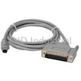
IDEC CORPORATION FC4A-KC2CA
Description
Cable Assembly 1.5m D-Sub to Circular
FC4A-KC2CA
Part Number
FC4A-KC2CA
Price
Request Quote
Manufacturer
IDEC CORPORATION
Lead Time
Request Quote
Category
Wire and Cables » Cable Assembly Other
Specifications
Manufacturer
IDEC Corporation
Manufacturers Part #
FC4A-KC2CA
Lead Time
4 Week Lead Time
Sub-Category
Cable Assemblies
Factory Pack Quantity
1
Datasheet

Extracted Text
Programmable Logic Controllers Programmable Logic Controllers MicroSmart Series MicroSmart Key features of the MicroSmart series include: • 10, 16, or 24 I/O All-in-one type CPU modules with Sink/ Source DC input and Relay Output • 20 I/O Slim type CPU modules with Sink/Source DC input and Transistor Sink or Source Output • 20 I/O Slim type CPU modules with Sink/Source DC input and Relay Output with high-speed Transistor Sink or Source Output • 40 I/O Slim type CPU modules with Sink/Source DC input and Transistor Sink or Source Output • AC Input, DC Input, Relay Output, Transistor Output, Com- bination I/O and Analog I/O expansion modules available • 24 I/O All-in-one CPU expandable to 88 I/O points; 20 I/O slim types expandable up to 148 or 244 I/O; 40 I/O slim type expandable up to 264 I/O points • Standard RS232 port, optional plug-in RS485/RS232 port • Optional memory cartridge or real-time clock and calendar cartridge • Data link to other MicroSmart modules, PLCs, PCs or HG UL Listed File No. E211795 series operator interfaces • Approved for Class 1–Div. 2 hazardous locations (UL1604) • Compact size Pulse Output/Trapezoidal Control Independent dual-axis control is available with two pulse out- puts. Locational values can be easily deŢned for precise posi- J tional (trapezoidal) control. • Pulse output instruction • PWM instruction (Pulse Width Modulation control) Pulse Output Function SpeciŢcations Number of output points 2 Maximum output frequency 20 kHz *Only one point of trapezoidal control is available. Setting the desired values enables you to precisely man- age the trapezoidal control Trapezoidal Control Operation mode (S1) 1 (RAMP) Steady pulse frequency (S1 + 1) 50 Hz Initial pulse frequency (S1 + 2) 10 Steady Speed Frequency change rate (S1 + 3) 2 5000 Present value (S1 + 6, 7) 10,000 Initial Speed RAMP S1 D1 0 ms Acceleration period Deceleration period www.idec.com USA: (800) 262-IDEC or (408) 747-0550, Canada: (888) 317-IDEC J-5 MicroSmart Series Programmable Logic Controllers CPU and Module Combination Examples All-In-One Type Maximum I/O 88 90 FC4A-N16B3 • Attach Maximum 4 Expansion 16 80 Modules • Maximum I/O 88 points 70 • Only FC4A-C24R2/C24R2C CPU FC4A-N16B3 16 FC4A-M24BR2 Module is expandable 24 60 FC4AN08B1 8 FC4A-R161 50 16 The maximum number of FC4A-N08B1 8 FC4A-R161 relay outputs that can be 16 40 FC4A-M24BR2 turned on simulta- FC4A-N08B1 8 24 FC4A-R161 neously is 33 points 16 FC4A-N08B1 FC4A-N08B1 including relay outputs 30 88 on the CPU module. 20 FC4A-C24R2 FC4A-C24R2 FC4A-C24R2 FC4A-C24R2 FC4A-C24R2 24 24 24 24 24 FC4A-C16R2 10 on CPU on CPU on CPU 16 on CPU on CPU FC4A-C10R2 10 on CPU on CPU 0 6 Inputs 9 Inputs 14 Inputs 30 Inputs 46 Inputs 38 Inputs 46 Inputs 4 Outputs 7 Outputs 10 Outputs 18 Outputs 10 Outputs 34 Outputs 42 Outputs 10 Total I/O 16 Total I/O 24 Total I/O 48 Total I/O 56 Total I/O 72 Total I/O 88 Total I/O Slim Type J Maximum I/O 264 FC4A-N32B3 250 32 FC4A-T32K3 • Attach Maximum 7 Expansion 32 FC4A-R32S3 Modules 32 FC4A-T32K3 FC4A-M24BR2 • Maximum I/O 200 24 32 - 148 points (D20K3, D20S3) FC4A-N32B3 32 - 244 points (D20RK1, D20RS1) FC4A-T32K3 FC4A-T32K3 -264 points (D40K3, D40S3) 32 32 FC4A-R32S3 FC4A-M24BR2 32 150 FC4A-T32K3 FC4A-T32K3 24 32 FC4A-R16S3 32 FC4A-N32B3 The maximum number of 16 32 relay outputs that can be FC4A-R16S3 FC4A-N16B3 FC4A-T32S3 FC4A-N32B3 16 16 turned on simulta- 100 FC4A-R32S3 32 32 FC4A-T32S3 FC4A-N32B3 neously is 54 points 32 32 32 including relay outputs FC4A-N32B3 FC4A-N32B3 on the CPU module. 32 32 FC4A-T32S3 FC4A-N32B3 FC4A-N32B3 32 32 32 50 FC4A-N32B3 FC4A-N32B3 FC4A-D20K3 FC4A-D40K3 32 32 FC4A-D20S3 FC4A-D40S3 FC4A-D40S3 FC4A-D40K3 FC4A-D40S3 FC4A-D20RK1 40 40 40 40 FC4A-D20RS1 FC4A-D20RS1 FC4A-D20RK1 on CPU on CPU on CPU on CPU 20 20 20 on CPU on CPU on CPU 0 12 Inputs 24 Inputs 24 Inputs 92 Inputs 120 Inputs 108 Inputs 152 Inputs 8 Outputs 16 Outputs 96 Outputs 64 Outputs 88 Outputs 136 Outputs 112 Outputs 20 Total I/O 40 Total I/O 120 Total I/O 156 Total I/O 208 Total I/O 244 Total I/O 264 Total I/O J-6 www.idec.com USA: (800) 262-IDEC or (408) 747-0550, Canada: (888) 317-IDEC Programmable Logic Controllers I/O Points I/O Points Programmable Logic Controllers Programmable Logic Controllers MicroSmart Series PID Control To automatically maintain a target water temperature (PID control), use the auto tuning function to perform sampling. Based on the determined PID parameters, PID control is executed automatically. (Slim type CPU units only.) Water Temperature High alarm value 33ºC Set point 30ºC Set point 30 Low alarm value 27ºC AT set point 25 AT set point 25ºC High alarm value 35 Low alarm value 27 Time Auto Tuning PID Control PID S1 S2 S3 S4 D1 CPU Modules - All-in-One Type Part Numbers J AC Power Type FC4A-C10R2* FC4A-C16R2* FC4A-C24R2 DC Power Type FC4A-C10R2C* FC4A-C16R2C* FC4A-C24R2C Item I/O Points 10 (6 in/ 4 out) 16 (9 in/7 out) 24 (14 in/10 out) Output Type Relay Output, 240V AC/30V DC, 2A Input Type 24V DC (Sink/Source) AC 100-240V AC, 50/60 Hz Power Voltage DC 24V DC Memory 4.8KB 15KB 27KB 88 maximum I/O Expandability N/A* N/A (up to 4 expansion I/O modules) 1. * I/O expansion modules not applicable to these two models. 2. For specifications see page J-15 & for dimensions see page J-25. 3. For options see J-11 & for accessories see J-12. www.idec.com USA: (800) 262-IDEC or (408) 747-0550, Canada: (888) 317-IDEC J-7 MicroSmart Series Programmable Logic Controllers CPU Modules - Slim Type Part Number FC4A-D20K3 FC4A-D20RK1 FC4A-D40K3 Item I/O Points 20 (12 in/ 8 out)* 20 (12 in/ 8 out) 40 (24 in/16 out)** Relay Output, 240V AC/30V DC, 2A* Output Type Transistor Sink Output 0.3A Transistor Sink Output 0.3A Sink Output 0.3A* Input Type 24V DC (Sink/Source) Power Voltage 24V DC Memory 27KB 31.2KB 31.2KB Expandability 148 maximum I/O (up to 7 expansion modules) 244 maximum I/O (up to 7 expansion modules) 264 maximum I/O (up to 7 expansion modules) Part Number FC4A-D20S3 FC4A-D20RS1 FC4A-D40S3 J Item I/O Points 20 (12 in/ 8 out)* 20 (12 in/ 8 out) 40 (24 in/16 out)** Relay Output, 240V AC/30V DC, 2A* Output Type Transistor Source Output 0.3A Transistor Source Output 0.3A Transistor, Source Output 0.3A* Input Type 24V DC (Sink/Source) Power Voltage 24V DC Memory 27KB 31.2KB 31.2KB Expandability 148 maximum I/O (up to 7 expansion modules) 244 maximum I/O (up to 7 expansion modules) 264 maximum I/O (up to 7 expansion modules) 1. * Transistor output 2 points and relay output 6 points. 2. **For MIL connector type modules, see page J-12 for cables and breakout modules. 3. For specifications see page J-15 & for dimensions see page J-25. 4. For options see J-11 & for accessories see J-12. J-8 www.idec.com USA: (800) 262-IDEC or (408) 747-0550, Canada: (888) 317-IDEC Programmable Logic Controllers Programmable Logic Controllers Programmable Logic Controllers MicroSmart Series Input Modules - 5 Types Part Number FC4A-N08B1 FC4A-N16B1 FC4A-N16B3 FC4A-N32B3 FC4A-N08A11 Item Input Points 8-point DC 16-point DC 16-point DC* 32-point DC* 8-point AC Input Type 24V DC (Sink/Source) 100 - 120V AC Power Voltage 24V DC 100 - 120V AC (50/60Hz) Terminal Removable screw terminal Removable screw terminal MIL connector MIL connector Removable screw terminal 1. For specifications see page J-19 & for dimensions see page J-25. 2. For options see J-11 & for accessories see J-12. 3. *For MIL connector type modules, see page J-12 for cables and breakout modules. Output Modules - 8 Types Part Number FC4A-R081 FC4A-R161 FC4A-T08K1 FC4A-T08S1 Item J Output Points 8-point Relay 16-point Relay 8-point Transistor 8-point Transistor Output Type Relay Output (1NO contact), 240V AC/30V DC, 2A Transistor sink output 0.3A Transistor Source Output 0.3A Terminal Removable screw terminal Part Number FC4A-T16K3 FC4A-T16S3 FC4A-T32K3 FC4A-T32S3 Item Output Points 16-point Transistor 16-point Transistor 32-point Transistor 32-point Transistor Output Type Transistor sink output 0.1A* Transistor source output 0.1A* Transistor sink output 0.1A* Transistor source output 0.1A* Terminal MIL connector 1. For specifications see page J-19 & for dimensions see page J-25. 2. For options see J-11 & for accessories see J-12. 3. *For MIL connector type modules, see page J-12 for cables and breakout modules. www.idec.com USA: (800) 262-IDEC or (408) 747-0550, Canada: (888) 317-IDEC J-9 MicroSmart Series Programmable Logic Controllers Combination I/O Modules - 2 Types Part Number FC4A-M08BR1 FC4A-M24BR2 Item I/O Points 8 (4 in/ 4 out) 24 (16 in/ 8 out) 1. For specifications see page J-21 Output Type Relay Output, 240V AC/30V DC, 2A & for dimensions see page J-25. 2. For options see J-11 & for acces- Input Type 24V DC (Sink/Source) sories see J-12. Terminal Removable terminal block Wire clamp terminal Analog I/O Modules - 4 Types Part Number FC4A-K1A1 FC4A-J2A1 FC4A-L03AP1 FC4A-L03A1 Item 1. For specifications see page J-22 & for J dimensions see page J-25. 2. For options see J-11 I/O Points 1 Analog Output 2 Analog Inputs 2 Analog Inputs, 1 Analog Output 2 Analog Inputs, 1 Analog Output & for accessories Voltage (0-10V DC) Voltage (0-10V DC) see J-12. Output Type – Current (4-20mA) Current (4-20mA) 3. New analog mod- Voltage (0-10V DC) Current (4-20mA) ules available Fall Voltage (0-10V DC) Thermocouple Input Type – Current (4-20mA) Resistance thermometer (RTD) ‘05. See page J-4 for details. Terminal Removable terminal block Expansion Module Examples Example 1 Example 2 Module Type No. Input Output Module Type No. Input Output CPU FC4A-C24R2 14 10 CPU FC4A-C24R2 14 10 DC Input FC4A-N16B1 16 0 DC Input FC4A-N08B1 8 0 DC Input FC4A-N16B1 16 0 DC Input/Relay Output FC4A-M08BR1 4 4 Relay Output FC4A-R161 0 16 Relay Output FC4A-R081 0 8 Relay Output FC4A-R161 0 16 Transistor Sink Output FC4A-T08K1 0 8 Total 46 42 Total 26 30 J-10 www.idec.com USA: (800) 262-IDEC or (408) 747-0550, Canada: (888) 317-IDEC Programmable Logic Controllers Programmable Logic Controllers Programmable Logic Controllers MicroSmart Series Optional Modules FC4A-PM32 Part Number FC4A-HPH1 FC4A-PH1 FC4A-PT1 FC4A-PM64 Item HMI Base Module (does not Type HMI Module Memory Cartridge Clock Cartridge come with HMI module) For mounting HMI module with For displaying and changing Description 32KB or 64KB – slim type CPU module required operands 1. For specifications see page J-24. Communication Adapters Part Number FC4A-PC1 FC4A-PC2 FC4A-PC3 Item J Type RS232C RS485 RS485 Screw Terminal Terminal Mini DIN Mini DIN Type 1. For specifications see page J-24. 2. Used for All-In-One CPU units only, or for FC4A-HPH1 unit shown above. Communication Modules for Slim Type CPUs Part Number FC4A-HPC1 FC4A-HPC2 FC4A-HPC3 FC4A-AS62M* Item Type RS232C RS485 RS485 AS-Interface Master Module Mini DIN for Slim Type CPU Mini DIN for Slim Type CPU Screw Terminal Type for Terminal – Module Module Slim Type CPU Module 1. For specifications see page J-24. 2. *FC4A-AS62M is compatible with CPUs: FC4A-D20RK1, FC4A-D20RS1, FC4A-D40K3, and FC4A-D40S3. (See Communication & Networking Section M for more information.) 3. New web server module available Fall ‘05. See page J-3 for details. www.idec.com USA: (800) 262-IDEC or (408) 747-0550, Canada: (888) 317-IDEC J-11 MicroSmart Series Programmable Logic Controllers Accessories MicroSmart Options MIL Connector Cables (Use with Breakout Modules) Description Length Part Number Item Item Length Part Number Programming cable Non-Shielded 0.5m FC9Z-H050B20 (Loader /user mode 3m/9.84’ FC4A-KC4CA selectable) 1m FC9Z-H100B20 O/I Interface Cable 2m FC9Z-H200B20 (MicroSmart port 1/2 FC4A-KC1CA RS232 to HG1B/2A) 16pt & 32pt 3m FC9Z-H300B20 1.5m/5’ I/O Modules O/I Interface Cable (20-wire) Shielded 0.5m FC9Z-H050A20 (MicroSmart port 1/2 FC4A-KC2CA RS232 to HG2F/3F/4F) 1m FC9Z-H100A20 2m FC9Z-H200A20 3m FC9Z-H300A20 Modem Cable 3m/9.84’ FC2A-KM1C Shielded Single Connectors 16pt & 32pt I/O Modules 5 ft FC9Z-H100C20A (20-wire) User 2.4m/7.87’ FC2A-KP1C Communication Cable Non-Shielded 0.5m FC9Z-H050B26 1m FC9Z-H100B26 2m FC9Z-H200B26 20pt & 40pt 3m FC9Z-H300B26 CPU Modules Analog Voltage Input Shielded (26-wire) 0.5m FC9Z-H050A26 Cables 1m/3.28’ FC4A-PMAC2P (included with slim 1m FC9Z-H100A26 type CPU only) 2m FC9Z-H200A26 J 3m FC9Z-H300A26 Shielded Single Connectors USB/RS232 Converter FC4A-USB 20pt & 40pt CPU Modules 5 ft FC9Z-H100C26A (26-wire) Breakout Modules Item Description Part Number 20 points BX1D-S20A (for 16 & 32 I/O expansion modules) 26 points (for 20 & 40 I/O CPU modules) BX1D-S26A J-12 www.idec.com USA: (800) 262-IDEC or (408) 747-0550, Canada: (888) 317-IDEC Programmable Logic Controllers Programmable Logic Controllers Programmable Logic Controllers MicroSmart Series Accessories con’t Description Pkg Qty Part Number Item 13-position terminal blocks for slim type CPU modules 2 FC4A-PMT13P (TB1 for FC4A-D20RK1/-D20RS1) 16-position terminal blocks for slim type CPU modules 2 FC4A-PMTS16P (TB2 for FC4A-D20RS1) 16-position terminal blocks for slim type CPU modules 2 FC4A-PMTK16P (TB2 for FC4A-D20RK1) 11-position terminal blocks for I/O modules 2 FC4A-PMT11P (8 point I/O modules) 10-position terminal blocks for I/O module 2 FC4A-PMT10P (16 point I/O modules) Direct Mounting Strips FC4A-PSP1P (for direct mounting of slim type CPU or I/O modules on 5 a panel) BNL6 End Clips J DIN Rails (1m/3.28’ long, 7.5mm height) BAA1000 DIN Rails (1m/3.28’ long, 10.5mm height) BNDN1000 White IDEC screwdriver (2.5mm) FC9Z-SD2 Blue IDEC screwdriver (3.5mm) FC9Z-SD1 20-position connector socket 2 FC4A-PMC20P (MIL connector for I/O modules) 26-position connector socket 2 FC4A-PMC26P (MIL connector for Slim Type CPU) 14-point input simulator switch (Use with FC4A-C24R2 FC4A-DS824-SW14 & FC4A-C24R2C) 9-point input simulator switch (Use with FC4A-C16R2 FC4A-DS824-SW9 & FC4A-C16R2C) 6-point input simulator switch (Use with FC4A-C10R2 FC4A-DS824-SW6 & FC4A-C10R2C) MicroSmart Users Manual FC9Y-B812-0A Windows-based programming software for IDEC PLCs (for more WINDLDR information, see page J-44). www.idec.com USA: (800) 262-IDEC or (408) 747-0550, Canada: (888) 317-IDEC J-13 MicroSmart Series Programmable Logic Controllers MicroSmart Packages MicroSmart Starter Kits Part Number Includes WindLDR Input Simulator Screwdriver HMI Switch Display Cables & Base Module Breakout 26-Wire I/O Cable Module Manuals 15w Power Supply MM-SMART-10 FC4A-C10R2, Input Simulator Switch, Screwdriver WindLDR, Cables & Manuals MM-SMART-16 FC4A-C16R2, Input Simulator Switch, Screwdriver WindLDR, Cables & Manuals MM-SMART-24 FC4A-C24R2, Input Simulator Switch, Screwdriver WindLDR, Cables & Manuals MM-SMART-20 FC4A-D20RK1, HMI Display & Base Module,15w Power Supply, Screwdriver WindLDR, Cables & Manuals FC4A-D40K3, HMI Display & Base Module,15w Power Supply, 26-Wire I/O Cable & Brea- MM-SMART-40 WindLDR, Cables & Manuals kout Module, Screwdriver MicroSmart Solution Packages Micro Operator Part Number Smart Power Supply Accessories Interface CPU WindLDR 15W WindO/I-NV2 Cables J WindMSG Manuals 50W MM-SMART-10-252 10 I/O HG1X 2 line – WindLDR, WindMSG, Cables & Manuals – 16 I/O HG1X 4 line – WindLDR, WindMSG, Cables & Manuals – MM-SMART-16-452 HG1X MM-SMART-10-HG1B 10 I/O HG1B RS232/485 15W WindLDR, WindO/I-NV2, Cables & Manuals E-Stop & Nameplate MM-SMART-16-HG1B 16 I/O HG1B RS232/485 15W WindLDR, WindO/I-NV2, Cables & Manuals E-Stop & Nameplate MM-SMART-24-HG1B 24 I/O HG1B RS232/485 15W WindLDR, WindO/I-NV2, Cables & Manuals E-Stop & Nameplate MM-SMART-20-HG1B 20 I/O HG1B RS232/485 50W WindLDR, WindO/I-NV2, Cables & Manuals E-Stop & Nameplate HG1B MM-SMART-40-HG1B 40 I/O HG1B RS232/485 50W WindLDR, WindO/I-NV2, Cables & Manuals E-Stop & Nameplate MM-SMART-16-HG2F-M 16 I/O HG2F Monochrome 15W WindLDR, WindO/I-NV2, Cables & Manuals E-Stop & Nameplate MM-SMART-16-HG2F-C 16 I/O HG2F Color 15W WindLDR, WindO/I-NV2, Cables & Manuals E-Stop & Nameplate MM-SMART-24-HG2F-M 24 I/O HG2F Monochrome 15W WindLDR, WindO/I-NV2, Cables & Manuals E-Stop & Nameplate MM-SMART-24-HG2F-C 24 I/O HG2F Color 15W WindLDR, WindO/I-NV2, Cables & Manuals E-Stop & Nameplate MM-SMART-20-HG2F-M 20 I/O HG2F Monochrome 50W WindLDR, WindO/I-NV2, Cables & Manuals E-Stop & Nameplate MM-SMART-20-HG2F-C 20 I/O HG2F Color 50W WindLDR, WindO/I-NV2, Cables & Manuals E-Stop & Nameplate HG2F MM-SMART-40-HG2F-M 40 I/O HG2F Monochrome 50W WindLDR, WindO/I-NV2, Cables & Manuals E-Stop & Nameplate MM-SMART-40-HG2F-C 40 I/O HG2F Color 50W WindLDR, WindO/I-NV2, Cables & Manuals E-Stop & Nameplate HG3F 10.4” TFT 24 I/O 60W WindLDR, WindO/I-NV2, Cables & Manuals E-Stop & Nameplate MM-SMART-24-HG3F Color HG4F 12.1” TFT MM-SMART-24-HG4F 24 I/O 60W WindLDR, WindO/I-NV2, Cables & Manuals E-Stop & Nameplate Color HG3F/4F J-14 www.idec.com USA: (800) 262-IDEC or (408) 747-0550, Canada: (888) 317-IDEC Programmable Logic Controllers Programmable Logic Controllers Programmable Logic Controllers MicroSmart Series General SpeciŢcations (CPU Module) FC4A-C10R2 FC4A-C16R2 FC4A-C24R2 FC4A-D20K3 FC4A-D20RK1 FC4A-D40K3 FC4A-C10R2C FC4A-C16R2C FC4A-C24R2C FC4A-D20S3 FC4A-D20RS1 FC4A-D40S3 AC Power Type: 100-240V AC Rated Voltage 24V DC DC Power Type: 24V DC AC Power Type: 85-264V AC Allowable Range 20.4 to 26.4V DC (including ripple) DC Power Type: 16.0 - 31.2V DC Rated Frequency AC Power Type: 50/60 Hz (47-63 Hz) — 0.25A (85V AC or 0.30A (85V AC or 0.45A (85V AC or Maximum Input Current 0.56A (26.4V DC) # 0.70A (26.4V DC) # 24V DC) 24V DC) 24V DC) ** 30VA/264V AC * 31VA/264V AC * 40VA/264V AC ** AC 15W/26.4V DC # 19W/26.4V DC # Max. Power 20VA/100V AC 22VA/100V AC 33VA/100V AC Consumption DC 3.8W/24V DC 4.6W/24V DC 8.7W/24V DC Not applicable Allowable Momentary 10 msec at the rated inputs and outputs (IEC61131) 10 msec (at 24V DC) Power Interruption Between power and terminal: 1500V AC, 1 min Between power and terminal: 500V AC, 1 min Dielectric Strength Between I/O and terminal: 1500V AC, 1 min Between I/O and terminal: 1500V AC, 1 min Between power and terminal: 10 MΩ (min), 500V DC Between power and terminal: 10 MΩ (min) Insulation Resistance Between I/O and terminal: 10 MΩ (min), 500V DC Between I/O and terminal: 10 MΩ (min) AC or DC power terminal: 1.5 kV, 50ns to 1µs DC power terminals: 1.0 kV, 50 nsec to 1µsec Noise Resistance I/O terminal (coupling clamp): 1.5 kV, 50ns to 1µs I/O terminals (coupling clamp): 1.5 kV, 50 nsec to 1µsec Inrush Current 35A max. 35A max. 40A max. 50A maximum (24V DC) Power Supply Wire 22 - 18AWG Operating Temperature 0 to 55°C Storage Temperature –25 to +70°C Operating Humidity 30-95% Level RH1 (no condensation) Operation: 0 to 2,000m (0 to 6,595 ft) Altitude Transport: 0 to 3,000m (0 to 9.840 ft) J Pollution Degree 2 (IEC60664) Corrosion Immunity Free from corrosive gases Degree of Protection IP20 Grounding Wire 16 AWG 22 AWG DIN rail mounted: 10 to 57Hz / amplitude 0.075mm, 57 to 150Hz / acceleration 9.8m/s2 (1G) Vibration Resistance Direct mounted: 2 to 25Hz / amplitude 1.6mm, 25 to 100Hz / acceleration 39.2m/s2 (4B) in each of 3 axes Shock Resistance 15G, 11ms, 3 shocks in each of 3 axes AC 230g 250g 305g Not Applicable Weight DC 240g 260g 310g 140g 185g 180g 1. * CPU module power consumption includes 250 mA sensor power. 2. ** CPU module (including 250 mA sensor power) + 4 I/O modules 3. # CPU module + 7 I/O modules Communication Port 1 SpeciŢcations Standards EIA RS232C Maximum Baud Rate 19200 bps Maintenance Communication Possible User Communication Possible Modem Communication Not possible Data Link Communication Not possible Cable Special Cables: FC2A-KC4C, FC2A-KP1C, FC4A-KC1CA, FC4A-KC2CA Isolation between Internal Circuit Not isolated and Communication Port www.idec.com USA: (800) 262-IDEC or (408) 747-0550, Canada: (888) 317-IDEC J-15 CPU General Specifications MicroSmart Series Programmable Logic Controllers Function SpeciŢcations (CPU Module) FC4A-C10R2 FC4A-C16R2 FC4A-C24R2 FC4A-D20K3 FC4A-D20RK1 FC4A-D40K3 FC4A-C10R2C FC4A-C16R2C FC4A-C24R2C FC4A-D20S3 FC4A-D20RS1 FC4A-D40S3 Stored program system Control System 35 basic instructions Instruction words 38 advanced 40 advanced 46 advanced 53 advanced 70 advanced 4,800 bytes 15,000 bytes 27,000 bytes 27,000 bytes 31,200 bytes (800 steps) (2,500 steps) (4,500 steps) (4,500 steps) (5,200 steps) Program Capacity Calculated 6 bytes per step User Program Internal EEPROM, Memory cartridge (option: EEPROM) Storage Basic instruction: 1.65 msec (1000 steps); END processing: 0.64 msec Processing Time (does not include expansion I/O service, clock function processing, data link processing and interrupt processing) Expandable I/O –– 4 modules 7 modules Modules Backup Data: Internal relay, shift register, counter, data register Backup Duration: Approx. 30 days (typical) at 25° C after backup battery fully charged Battery: Lithium secondary battery RAM Backup Charging Time: Approx. 15 hours for charging from 0% to 90% of full charge Battery Life: 5 years Replaceability: Impossible to replace battery 14 input, 10 output 12 input, 8 output 12 input, 8 output 24 input, 16 output I/O Points 6 input, 4 output 9 input, 7 output Expansion: 64 I/O Expansion: 128 I/O Expansion: 224 I/O Expansion: 224 I/) 256 1024 Internal Relay 64 128 Shift Register 400 1300 Data Register Expansion Data — 6000 Register 32 100 Counter J Timer (1-sec, 32 100 100-msec, 10-msec, 1-msec) Power failure check, watchdog timer, data link connection, user program EEPROM sum check, Self-Diagnostic timer/counter preset value sum check, user program RAM sum check, keep data, user program syntax, user program writing, Function CPU module, clock IC, I/O bus initialize, user program execution 3 to 15 msec (1-msec increments) Input Filter Catch Input/ 4 input (I2 through I5) Minimum turn on pulse width: 40 µsec maximum Minimum turn off pulse width: 150 µsec maximum Interrupt Input Total 4 points: Single/two-phase selectable: 20kHz (1 point) Total 4 points: Single/two-phase selectable: 20kHz (2 points) Single-phase: 5kHz (3 points) Single-phase: 5kHz (2 points) High-Speed Counter Counting Range 0 to 65535 (16 bits), Operation Mode: Rotary encoder mode and adding counter mode 1 point 2 points 1 point Analog Potentiometer Data Range: 0 to 255 1 point, 0 to 10V DC Input Voltage Range, approx. 100kΩ Input Analog Voltage Input — Impedance, data range 0-255 (8 bit) —2 points, max. frequency 20kHz Pulse Output Sensor Power 24V DC (+10% to -15%), 250 mA, no overload detection — Isolated from the internal circuit Supply RS232C Maintenance Communication, User Communication, Modem Communication Port 1 — Possible: RS232C or RS485 (Maintenance communication, data link) Port 2 (optional) Clock Function Possible Year, month, day, day of week, hour, minute, second (optional) Possible Select either clock or memory cartridge Memory Cartridge Possible (optional) Possible Possible using HMI Base Module HMI Module (optional) J-16 www.idec.com USA: (800) 262-IDEC or (408) 747-0550, Canada: (888) 317-IDEC Programmable Logic Controllers CPU Function Specifications Programmable Logic Controllers Programmable Logic Controllers MicroSmart Series DC Input/Relay Output SpeciŢcations (CPU Module) DC Input SpeciŢcations for CPU modules FC4A-C10R2 FC4A-C16R2 FC4A-C24R2 FC4A-D20K3 FC4A-D20RK1 FC4A-D40K3 FC4A-C10R2C FC4A-C16R2C FC4A-C24R2C FC4A-D20S3 FC4A-D20RS1 FC4A-D40S3 24V DC sink / source input signal Rated Input Voltage 20.4 to 28.8V DC 20.4 to 26.4V DC Allowable Range I0, I1: 11mA, I2 to I7, I10 to I15: 7mA I0, I1, I6, I7: 5mA/point, I2 to I5, I10 to I27: 7mA/point Rated Input Current I0, I1: 2.1kΩ, I2 to I7, I10 to I15: 3.4kΩ I0, I1, I6, I7: 5.7kΩ, I2 to I5, I10 to I27: 3.4kΩ Input Impedance I0 to I5: 35µsec + Filter Value I0 to I7: 35µsec + Filter Value OFF/ON I6, I7, I10 to I15: 40µsec + Filter Value I10 to I27: 40µsec + Filter Value OFF/ON Time I0, I1: 45µsec + Filter Value I0, I1, I6, I7: 45µsec + Filter Value ON/OFF I2 to I7, I10 to I15: 150µsec + Filter Value I2 to I5, I10 to I27: 150µsec + Filter Value 6 inputs 9 inputs 14 inputs 12 inputs 12 inputs 24 inputs, Input Points 6/1 common 9/1 common 14/1 common 12/1 common 12/1 common 12/1 common FL26A2MA FL26A2MA MC1.5/13-G-3.81BK On Mother Board — (Oki Electric (Oki Electric (Phoenix Contact) Cable) Cable) Connector Insertion/Removal — 100 times minimum Durability Between input terminals: Not isolated Isolation Internal circuit: Photocoupler isolated Type 1 (IEC61131) Input Type Not needed External Load for I/O Interconnection Static Signal Determination Method Both sinking and sourcing input signals can be connected. If any input exceeding the rated value is applied, Effect of Improper Input Connection permanent damage may be caused. 3m (9.84 ft) Cable Length J Relay Output SpeciŢcations for CPU modules FC4A-C10R2 FC4A-C16R2 FC4A-C24R2 FC4A-D20RK1 FC4A-C10R2C FC4A-C16R2C FC4A-C24R2C FC4A-D20RS1 4 points 7 points 10 points 8 points Output Points 2 points COM0 3 points 4 points 4 points (transistor output) 1 point 2 points 4 points 3 points COM1 Output Points per Common –1 point 1 point 2 points COM2 –– 1 point 1 point COM3 1NO Type of Output 2A Maximum Load Current Per point 8A Per Common 0.1mA, 0.1V DC (reference value) Minimum Switching Load 30mΩ maximum Initial Contact Resistance 100,000 operations (rated load) @ 1,800 operations/hr Electrical Life 200,000 operations (no load) @ 18,000 operations/hr Mechanical Life 240V AC/2A, 24V DC/2A (30V DC / 2A) Rated Load Current (resistive/inductive) Between output and terminals: 1500V AC, 1 minute Dielectric Strength Between output terminals and internal circuit: 1500V AC, 1 minute Between output terminals (COMs): 1500 V AC, 1 minute On Mother MC1.5/16-G-3.81BK — (Phoenix Contact) Board Connector Insertion/ — 100 times minimum Removal Durability www.idec.com USA: (800) 262-IDEC or (408) 747-0550, Canada: (888) 317-IDEC J-17 MicroSmart Series Programmable Logic Controllers Transistor Sink and Source Output SpeciŢcations (CPU Module) Transistor Sink and Source Output SpeciŢcations for CPU modules FC4A-D20K3 FC4A-D20RK1 FC4A-D40K3 FC4A-D20S3 FC4A-D20RS1 FC4A-D40S3 8 points, 8/1 common 2 points, 2/1 common 16 points, 8/1 common Output Points and Common Line FC4A-D20K3/D20RK1/D40K3 = Sink Output Type of Output FC4A-D20S3/D20RS1/D40S3 = Source Output 24V DC Rated Load Voltage 20.4 to 28.8V DC Operating Load Voltage Range 0.3A per output point Rated Load Current 1A per common line Maximum Load Current 1V maximum (voltage between COM and output terminals when output is on) Voltage Drop (ON Voltage) 1A maximum Inrush Current 0.1 mA maximum Leakage Current 39V±1V Clamping Voltage 8W Maximum Lamp Load L/R = 10ms (28.8V DC, 1Hz) Inductive Load 100mA maximum, 24V DC (power voltage at the +V or -V terminal) External Current Draw Between output terminal and internal circuit: Photocoupler isolated Isolation Between output terminals: Not isolated FL26A2MA MC1.5/16-G-3.81BK FL26A2MA On Mother Board (Oki Electric Cable) (Phoenix Contact) (Oki Electric Cable) Connector Insertion/Removal 100 times minimum Durability 5 µs (Q0, Q1), 300 µs max (Q2 to Q7, Q10 to Q17) Turn ON time Output Delay 5 µs (Q0, Q1), 300 µs max (Q2 to Q7, Q10 to Q17) Turn OFF time J J-18 www.idec.com USA: (800) 262-IDEC or (408) 747-0550, Canada: (888) 317-IDEC Programmable Logic Controllers Programmable Logic Controllers Programmable Logic Controllers MicroSmart Series Input/Relay Output Specifications (Expansion Modules) Input Module SpeciŢcations DC Input AC Input FC4A-N08B1 FC4A-N16B1 FC4A-N16B3 FC4A-N32B3 FC4A-N08A11 Input Points 8 points (8/1 common) 16 points (16/1 common) 32 points (16/1 common) 8 points (4/1 common) Rated Input Voltage 24V DC sink/source input signal 100 - 120V AC (50-60Hz) Input Voltage Range 20.4 to 28.8V DC 85 to 132V AC Rated Input Current 7mA/point (24V DC) 5mA/point (24V DC) 7.5mA/pt (100V AC, 60Hz) Input Impedance 3.4 kΩ 4.4 kΩ 0.8kΩ (60Hz) ON time: 4 msec ON time: 25 msec Input Delay Time OFF time: 4 msec OFF time: 30 msec Between input In the same commons: not isolated Not isolated terminals In different commons: 500V Isolation Internal circuit Photocoupler isolated 2500V (photocoupler isolated) External Load for I/O Not needed Interconnection Signal Determination Method Static Effect of Improper Input Connec- Both sinking and sourcing input signals can be connected. If any input exceeding the rated value is applied, permanent damage may be caused. tion Cable Length 3m (9.84 ft) in compliance with electromagnetic immunity On Mother Board MC1.5/10-G-3.81BK (Phoenix contact) FL20A2MA (Oki Electric Cable) Connector Insertion/Removal 100 times minimum Durability 25 mA (5V DC) 40 mA (5V DC) 35 mA (5V DC) 65 mA (5V DC) 60mA (5V DC) All Inputs ON Internal 0 mA (24V DC) 0 mA (24V DC) 0 mA (24V DC) 0 mA (24V DC) 0mA (24V DC) Current 5 mA (5V DC) 5 mA (5V DC) 5 mA (5V DC) 10 mA (5V DC) 30mA (5V DC) Draw All Inputs OFF 0 mA (24V DC) 0 mA (24V DC) 0 mA (24V DC) 0 mA (24V DC) 0mA (24V DC) J Weight 85g 100g 65g 100g – Relay Output Module SpeciŢcations FC4A-R081 FC4A-R161 Output Points and Common Lines 8 points (4/1 common) 16 points (8/1 common) Output Type 1NO per point 2A Maximum Load Current per common 7A 8A Minimum Switching Load 0.1 mA/0.1V DC (reference value) Initial Contact Resistance 30 mΩ maximum 100,000 operations minimum Electrical Life (rated load 1,800 operations/hour) 20,000,000 operations minimum Mechanical Life (no load 18,000 operations/hour) Rated Load (resistive/inductive) 240V AC/2A, 30V DC/2A Between output and terminals: 1500V AC, 1 minute Dielectric Strength Between output terminals and internal circuit: 1500V AC, 1 minute Between output terminals (COMs): 1500 V AC, 1 minute MC1.5/11-G-3.81BK MC1.5/10-G-3.81BK On Mother Board (Phoenix contact) (Phoenix contact) Connector Insertion/Removal 100 times minimum Durability 30 mA (5V DC) 45 mA (5V DC) All Inputs ON 40 mA (24V DC) 75 mA (24V DC) Internal Current Draw 5 mA (5V DC) 5 mA (5V DC) All Inputs OFF 0 mA (24V DC) 0 mA (24V DC) Weight 110g 145g www.idec.com USA: (800) 262-IDEC or (408) 747-0550, Canada: (888) 317-IDEC J-19 MicroSmart Series Programmable Logic Controllers Transistor Output SpeciŢcations (Expansion Modules) Transistor Output Module SpeciŢcations FC4A-T08K1 FC4A-T16K3 FC4A-T32K3 FC4A-T08S1 FC4A-T16S3 FC4A-T32S3 Output Points 8 points (8/1 common) 16 points (16/1 common) 32 points (16/1 common) FC4A-T�K�: Transistor sink output Output Type FC4A-T�S�: Transistor source output Rated Load Voltage 24V DC Operating Load Voltage Range 20.4 to 28.8V DC 0.3A per output point Rated Load Current 0.1A per output point (at 28.8V DC) (at 28.8V DC) per point 0.36A (at28.8V DC) 0.12A (at 28.8V DC) Maximum Load Current per common 3A (at 28.8V DC) 1A (at 28.8V DC) Voltage Drop (ON Voltage) 1V maximum (between COM and output terminals when output is on) Inrush Current 1A maximum Leakage Current 0.1A maximum Clamping Voltage 39V ± 1V Maximum Clamping Load 8W Inductive Load L/R = 10 msec (DC 28.8V, 1Hz) FC4A-T�K�: 100mA maximum, 24V DC (power voltage at the +V) External Current Draw FC4A-T�S�: 100mA maximum, 24V DC (power voltage at the -V) Between output terminal and internal circuit: Photocoupler isolated Isolation Between output terminals: Not isolated Type (on Mother MC1.5/10-G-3.81BK FL20A2MA (Oki Electric Cable) (Phoenix contact) Board) Connector Insertion/Removal J 100 times minimum Durability 10mA (5V DC) 10mA (5V DC) 20mA (5V DC) All Inputs ON 20mA (24V DC) 40mA (24V DC) 70mA (24V DC) Internal Current Draw 5mA (5V DC) 5mA (5V DC) 10mA (5V DC) All Inputs OFF 0mA (24V DC) 0mA (24V DC) 0mA (24V DC) Turn ON time 300µsec maximum Output Delay Turn OFF time 300µsec maximum Weight 85g 70g 105g J-20 www.idec.com USA: (800) 262-IDEC or (408) 747-0550, Canada: (888) 317-IDEC Programmable Logic Controllers Programmable Logic Controllers Programmable Logic Controllers MicroSmart Series Combination I/O SpeciŢcations (Expansion Modules) Combination I/O Module SpeciŢcations FC4A-M08BR1 FC4A-M24BR2 Input Points 4 points (4/1 common) 16 points (16/1 common) Rated Input Voltage 24V DC sink/source input signal Input Voltage Range 20.4 to 28.8V DC Range Input Current 7 mA/point (24V DC) Input Impedance 3.4 kΩ Turn ON Time 4 msec (24V DC) Turn OFF Time 4 msec (24V DC) Between input terminals: Not isolated Isolation Internal circuit: Photocoupler isolated External Load for I/O Interconnection Not needed Signal Determination Method Static Both sinking and sourcing input signals can be connected. If any input Effect of Improper Input Connection exceeding the rated value is applied, permanent damage may be caused. Cable Length 3m (9.84 ft) in compliance with electromagnetic immunity Output Points 4 points (4/1 common) 8 points (8/2 common) Output Type 1NO per point 2A Maximum Load Current per common 7A Minimum Switching Load 0.1 mA/0.1V DC (reference value) Initial Contact Resistance 30 mΩ maximum J Electrical Life 100,000 operations minimum (rated load 1,800 operations/hour) Mechanical Life 20,000,000 operations minimum (no load 18,000 operations/hour) Rated Load (resistive/inductive) 240V AC/2A, 30V DC/2A Between output and or terminals: 1,500V AC, 1 minute Dielectric Strength Between output terminal and internal circuit: 1,500V AC, 1 minute Between output terminal (COMs): 1,500V AC, 1 minute MC1.5/11-G-3.81BK Input: F6018-17P (Fujicon) on Mother Board (Phoenix contact) Output: F6018-11P (Fujicon) Connector Insertion/Removal 100 times minimum — Durability 25 mA (5V DC) 65 mA (5V DC) All Inputs ON 20 mA (24V DC) 45 mA (24V DC) Internal Current Draw 5 mA (5V DC) 10 mA (5V DC) All Inputs OFF 0 mA (24V DC) 0 mA (24V DC) Weight 95g 140g www.idec.com USA: (800) 262-IDEC or (408) 747-0550, Canada: (888) 317-IDEC J-21 Relay Output Specifications DC Input Specifications MicroSmart Series Programmable Logic Controllers Analog I/O SpeciŢcations (Expansion Modules) Analog I/O Module SpeciŢcations FC4A-L03A1 FC4A-L03AP1 FC4A-J2A1 FC4A-K1A1 22 2 — Input Points Voltage Input (0 to 10V DC) Thermocouple Voltage Input (0 to 10V DC) Input Signal Type — Current Input (4 to 20 mA DC) Resistance Thermometer Current Input (4 to 20 mA DC) 11 — 1 Output Points Voltage Output (0 to 10V DC) Voltage Output (0 to 10V DC) Voltage Output (0 to 10V DC) Output Signal Type — Current Output (4 to 20 mA Current Output (4 to 20 mA DC) Current Output (4 to 20 mA DC) DC) 24V DC Rated Power Voltage 20.4 to 28.8V DC Allowable Voltage Range MC1.5/11-G-3.81BK (Phoenix contact) On Mother Board Connector Insertion/Removal 100 times minimum Durability 50 mA (5V DC) 50 mA (5V DC) 50 mA (5V DC) 50 mA (5V DC) Internal Internal Power 0 mA (24V DC) 0 mA (24V DC) 0 mA (24V DC) 0 mA (24V DC) Current External Power 40 mA (24V DC) 40 mA (24V DC) 40 mA (24V DC) 40 mA (24V DC) Draw 85g Weight Analog Output SpeciŢcations FC4A-L03A1, FC4A-L03AP1, FC4A-K1A1 Output Signal Type Voltage Output Current Output 0 to 10V DC 4 to 20 mA DC Output Range 2 kΩ minimum 300Ω maximum Load Impedance Resistive load Applicable Load Type 20 msec Setting Time 20 msec + 1 scan time Total Output System Transfer Time ±0.2% of full scale Maximum Error at 25°C J ±0.015% of full scale/°C Temperature Coefficient ±0.5% of full scale Repeatability after Stabilization Time ±1% of full scale — Output Voltage Drop Output Error ±0.2% of full scale Non-lineality 1 LSB maximum Output Ripple 0% Overshoot ±1% of full scale Total Error 4096 increments (12 bits) Digital Resolution 2.5 mV 4 µA Output Value of LSB 0 to 4095 (12-bit data); -32768 to 32767 (optional range designation) Data Data Type in Application Program See note on page J-23 Yes Monotonicity — Detectable (See note on page J-23) Current Loop Open ±3% max. when a 500V clamp is applied to the power and I/O wiring Maximum Temporary Deviation during Electrical Noise Tests Twisted pair shielded cable recommended for improved noise immunity Noise Cable No crosstalk because of 1 channel output Crosstalk 500V between output and power circuit Dielectric Strength Photocoupler between output and internal circuit Type of Protection No damage Effect of Improper Output Connection Using software programming Selection of Analog Output Signal Type Impossible (approx. 10 years) Calibration or Verification to Maintain Rated Accuracy J-22 www.idec.com USA: (800) 262-IDEC or (408) 747-0550, Canada: (888) 317-IDEC Programmable Logic Controllers Programmable Logic Controllers Programmable Logic Controllers MicroSmart Series Analog Input SpeciŢcations (Expansion Modules) Analog Input SpeciŢcations FC4A-L03A1, FC4A-J2A1 FC4A-L03AP1 Input Signal Type Voltage Input Current Input Thermocouple Resistance Thermometer Type K (0 to 1300°C) Pt 100 3-wire type Input Range 0 to 10V DC 4 to 20 mA DC Type J (0 to 1200°C) (-100 to 500°C) Type T (0 to 400°C) 1 MΩ minimum 10Ω 1 MΩ minimum 1 MΩ minimum Input Impedance —— — 200Ω maximum Allowable Conductor Resistance —— — 1.0 mA maximum Input Detection Current 16 msec maximum 50 msec maximum Sample Duration Time 16 msec maximum 50 msec maximum Sample Repetition Time 32 msec + 1 scan time * 100 msec + 1 scan time * Total Input System Transfer Time Single-ended input Differential input Type of Input Self scan Operating Mode ∑Δ type ADC Conversion Method ±0.2% of full scale plus Maximum Error at 25°C ±0.2% of full scale reference junction compensa- ±0.2% of full scale tion accuracy (±4°C maximum) ±0.006% of full scale / °C Temperature Coefficient Input Error Repeatability after ±0.5% of full scale Stabilization Time ±0.2% of full scale Non-lineality ±1% of full scale Maximum Error 4096 increments (12 bits) Digital Resolution 2.5 mV 4 µA K: 0.325°C; J: 0.300°C; T: 0.100°C 0.15°C Input Value of LSB Data Type in Application 0 to 4095 (12-bit data); -32768 to 32767 (optional range designation) ** Data Program Yes Monotonicity J Detectable # Input Data Out of Range Maximum Temporary Accuracy is not assured when ±3% maximum when a 500V clamp voltage is applied to the power and I/O wiring Deviation during noise is applied Electrical Noise Tests Common Mode Common mode reject ratio (CMRR): -50 dB Characteristics Noise 16V DC Resistance Common Mode Voltage No Input Filter Twisted pair shielded cable recommended for Cable — improved noise immunity 2 LSB maximum Crosstalk 500V between input and power circuit Dielectric Strength Photocoupler between input and internal circuit Type of Protection No damage Effect of Improper Input Connection Maximum Permanent Allowed 13V DC 40 mA DC — Overload (No damage) Using software programming Selection of Analog Input Signal Type Calibration or Verification to Maintain Impossible (approx. 10 years) Rated Accuracy NOTES FOR ANALOG EXPANSION UNITS: 1. * Total input system transfer time = Sample repetition time x 2 + 1 scan time 2. ** The 12-bit data (0 to 4095) processed in the analog I/O module can be linear-converted to a value between -32768 and 32767. Select the optional range designations and analog I/O data minimum and maximum values by using data registers allocated to analog I/O modules. 3. # When an error is detected, a corresponding error code is sorted to a data register allocated to analog I/O operating status. www.idec.com USA: (800) 262-IDEC or (408) 747-0550, Canada: (888) 317-IDEC J-23 MicroSmart Series Programmable Logic Controllers Communication Adapter and Communication Module SpeciŢcations (Expansion Modules) Communication Adapter and Communication Module SpeciŢcations FC4A-PC1 FC4A-PC2 FC4A-PC3 FC4A-HPC1 FC4A-HPC2 FC4A-HPC3 EIA RS232C EIA RS485 EIA RS485 Standards Computer link: 19200 bps Maximum Baud Rate 19200 bps 19200 bps Data link: 38400 bps Possible Possible Possible Maintenance Communication Possible Impossible Impossible User Communication Possible Impossible Impossible Modem Communication Impossible Impossible Possible Data Link Communication special cable special cable 200m Maximum Cable Length —— 31 Quantity of Slave Stations Isolation between Internal Circuit and Not isolated Communication Port Twisted-pair shielded cable with Recommended Cable for RS485 — 2 a minimum core wire of 0.3 mm — 85 Ω/km maximum Conductor Resistance — 20 Ω/km maximum Shield Resistance Option SpeciŢcations Optional HMI Module SpeciŢcations FC4A-PH1 Power Voltage 5V DC (supplied from the CPU module) J Internal Current Draw 200mA DC Weight 20g Optional Memory Cartridge SpeciŢcations FC4A-PM32 FC4A-PM64 Memory Type EEPROM Accessible Memory Capacity 32 KB 64 KB Hardware for Storing Data CPU module Software for Storing Data WindLDR Quantity of Store Programs One user program can be stored on one memory cartridge Optional Clock Cartridge SpeciŢcations FC4A-PT1 Accuracy ±30 sec/month (typical) at 25°C Backup Duration Approx. 30 days (typical) at 25°C after backup battery fully charged Battery Lithium secondary battery Charging Time Approx. 10 hours for charging from 0% to 90% of full charge Replaceability Impossible to replace battery J-24 www.idec.com USA: (800) 262-IDEC or (408) 747-0550, Canada: (888) 317-IDEC Programmable Logic Controllers Programmable Logic Controllers Programmable Logic Controllers MicroSmart Series Dimensions CPU Modules: all dimensions in mm FC4A-C10R2, FC4A-C16R2 FC4A-C10R2C, FC4A-C16R2C FC4A-C24R2, FC4A-C24R2C FC4A-C10R2,FC4A-C16R2 FC4A-C24R2 80.0 70.0 95.0 70.0 FC4A-D20K3,FC4A-D20S3 FC4A-D20RK1,FC4A-D20RS1 FC4A-D40K3,FC4A-D40S3 47.5 11.3 70.0 35.4 11.3 70.0 47.5 14.6 70.0 Expansion Modules: FC4A-N08B1, FC4A-N08A11, FCA-T08K1, FC4A-M08BR1, FC4A-N08B1, FC4A-L03AP1, FC4A-T08K1,FC4A-M08BR1, FC4A-K1A1 FC4A-R081, FC4A-L03AP1, FC4A-T08S1, FC4A-K1A1, FC4A-L03A1, FC4A-R081 FC4A-J2A1 FC4A-T08S1,FC4A-L03A1,FC4A-J2A1 FC4A-N16B3,FC4A-T16K3,FC4A-T16S3 FC4A-HPC1,FC4A-HPC2,FC4A-HPC3 3.8 23.5 14.6 70.0 3.8 17.6 11.3 70.0 22.5 13.9 70.0 J FC4A-N16B1,FC4A-R161 FC4A-N32B3,FC4A-T32K3,FC4A-T32S3 FC4A-HPH1 14.6 70.0 3.8 29.7 11.3 70.0 38.0 13.9 71.0 3.8 23.5 FC4A-M24BR2 Example: 9.0 95.0 23.5 23.5 9.0 9.0 95.0 23.5 23.5 9.0 This figure illustrates a 3.8 39.1 1.0 70.0 EXAMPLE: system setup with the This figure illustrates a FC4A-C24R2 All-in-one system setup with the type CPU, an 8-point FC4A-C24R2 All-in-one relay output module, type CPU, an 8-point and a 16-point DC input relay output module, module, mounted on a and a 16-point DC input 35mm DIN rail using module, mounted on a 35mm DIN rail using BNL6 mounting clips. BNL6P mounting clips. DIN Rail DIN Rail BNL6P Mounting Clip BNL6 Mounting Clip www.idec.com USA: (800) 262-IDEC or (408) 747-0550, Canada: (888) 317-IDEC J-25 90.0 4.5* 90.0 90.0 90.0 4.5* 90.0 90.0 90.0 90.0 45.0 45.0 35.0 90.0 35.0 90.0 4.5* 90.0 90.0 4.5* 90.0 4.5* 90.0 MicroSmart Series Programmable Logic Controllers Mounting Hole Layout CPU Modules: FC4A-C10R2, FC4A-C10R2C FC4A-C24R2, FC4A-C10R2 FC4A-C20K3 FC4A-C20RK1,FC4A-D40K3 FC4A-C16R2, FC4A-C16R2C FC4A-C24R2 FC4A-C24R2C FC4A-C20RS1,FC4A-D40S3 FC4A-C16R2 FC4A-D20S3 35.4 47.5 80.0 95.0 24.1 24.1 68.0 83.0 3.0 3.0 Expansion Modules: FC4A-N08B1, FC4A-N16B1, FC4A-N08B1, FC4A-N08A11, FC4A-R081, FC4A-R161, FC4A-N16B1, FC4A-R081, FC4A-T08K1, FC4A-T08S1, FC4A-R161, FC4A-T08K1, FC4A-N16B3 FC4A-N32B3 FC4A-M08BR1, FC4A-L03A1 EXAMPLE: FC4A-T08S1, FC4A-M08BR1, FC4A-L03AP1, FC4A-J2A1, FC4A-T16K3 FC4A-T32K3 Mounting hole layout for FC4A-C24R2 and FC4A-L03A1, FC4A-L03AP1, FC4A-K1A1 FC4A-T16S3 FC4A-T32S3 23.5mm-wide I/O modules. FC4A-J2A1, FC4A-K1A1 29.7 17.6 23.5 6.3 6.3 6.3 12.3 23.5 23.5 23.5 J 3.0 3.0 3.0 3.0 15.3 23.5 23.5 23.5 83.0 3.0 3.0 3.0 EXAMPLE: FC4A-HP1C Mounting hole layout for, from left, FC4A-HPH1 FC4A-M24BR2 FC4A-HPC2 FC4A-HPH1, FC4A-D20K3, FC4A-HPC3 FC4A-N16B3, FC4A-N32B3, and 38.0 FC4A-M24R2 modules. 39.1 20.3 22.5 6.3 4.8 41.8 17.6 17.6 29.7 3.0 3.0 3.0 3.0 3.0 41.8 17.6 17.6 29.7 3.0 3.0 3.0 J-26 www.idec.com USA: (800) 262-IDEC or (408) 747-0550, Canada: (888) 317-IDEC 2-ş4.3 2-ø4.3 2-ø4.3 2-ø4.3 2-ø4.3 2-ş4.3 2-ş4.3 2-ø 4.3 2-ø 4.3 10-ø4.3 Programmable Logic Controllers 90.0 83.0 90.0 103.0 90.0 103.0 90.0 83.0 90.0 90.0 103.0 103.0 90.0 103.0 90.0 103.0 90.0 103.0 83.0 103.0 90.0 103.0 103.0 Programmable Logic Controllers Programmable Logic Controllers MicroSmart Series Usage Limits I/O Usage Limits All-in-one Type CPU Modules: Input Voltage (V DC) Ambient temperature Input Voltage (V DC) Ambient temperature Input Voltage (V DC) Ambient temperature 55°C 45°C 45°C 28.8V 28.8V 28.8V Ambient Ambient temperature temperature 26.4V 26.4V 26.4V 55°C 55°C When using at an operating ambient 0 50% 100% 0 50% 100% 0 50% 100% temperature above 40°C, reduce the I/O Simultaneous ON Ratio (%) I/O Simultaneous ON Ratio (%) I/O Simultaneous ON Ratio (%) input voltage or the quantity of I/O points that turn on simultaneously. Slim Type CPU Modules: Input Voltage (V DC) Ambient temperature Input Voltage (V DC) Ambient temperature Input Voltage (V DC) Ambient temperature 40°C 55°C 40°C 26.4V 26.4V 26.4V Ambient Ambient temperature 24.0V temperature 24.0V 24.0V 55°C 55°C 0 50% 100% 0 50% 100% 0 50% 100% I/O Simultaneous ON Ratio (%) I/O Simultaneous ON Ratio (%) I/O Simultaneous ON Ratio (%) Input Usage Limits Input Voltage (V DC) Ambient temperature Input Voltage (V DC) Ambient temperature Input Voltage (V DC) Ambient temperature Input Voltage (V DC) Ambient temperature Input Voltage (V DC) Ambient temperature 55°C 45°C 30°C 55°C 45°C 28.8V 28.8V 28.8V 28.8V 28.8V 26.4V 26.4V 26.4V 26.4V 26.4V Ambient Ambient Ambient 24.0V 24.0V 24.0V 24.0V 24.0V temperature temperature temperature J 55°C 55°C 55°C 0 50% 100% 0 50% 100% 0 50% 100% 0 50% 100% 0 50% 100% I/O Simultaneous ON Ratio (%) I/O Simultaneous ON Ratio (%) I/O Simultaneous ON Ratio (%) I/O Simultaneous ON Ratio (%) I/O Simultaneous ON Ratio (%) Internal Circuits Input Internal Circuits Output Internal Circuit (Slim Type) SINKOUTPUT ALL-IN-ONETYPE SLIMTYPE +V I0, I1, I6, I7 I0, I1 4.7 kΩ 1.8 kΩ Input Input Output Internal Circuit COM COM COM(-) I2 to I15 I2 to I5 and I10 to I27 SOURCEOUTPUT COM(+) 3.3 kΩ 3.3 kΩ Input Input Output Internal COM COM Circuit -V www.idec.com USA: (800) 262-IDEC or (408) 747-0550, Canada: (888) 317-IDEC J-27 Internal Circuit Internal Circuit Internal Circuit Internal Circuit MicroSmart Series Programmable Logic Controllers Internal Circuits Input Internal Circuits (Expansion Modules) Output Internal Circuits FC4A-N081,FC4A-N16B1 FC4A-T08K1,FC4A-T16K3,FC4A-T32K3 3.3 kΩ +V Input Output Internal COM Circuit FC4A-N16B3,FC4A-N32B3 COM(-) 4.3 kΩ Input FC4A-T08S1,FC4A-T16S3,FC4A-T32S3 COM COM(+) FC4A-M08BR1,FC4A-M24BR2 Output 3.3 kΩ Internal Input Circuit -V COM FC4A-N08A11 Input J COM Analog I/O Module Input Circuit Output Circuit +V2 +V1 + 15 MΩ 1 kΩ NC(A) - 1 kΩ + (B') Input Data 10 Ω 1 kΩ - (B) Input Selection Signal - V1 J-28 www.idec.com USA: (800) 262-IDEC or (408) 747-0550, Canada: (888) 317-IDEC Programmable Logic Controllers Multiplexer Internal Circuit Internal Circuit Internal Circuit Internal Circuit Output Circuit
Frequently asked questions
How does Electronics Finder differ from its competitors?

Is there a warranty for the FC4A-KC2CA?
Which carrier will Electronics Finder use to ship my parts?
Can I buy parts from Electronics Finder if I am outside the USA?
Which payment methods does Electronics Finder accept?
Why buy from GID?

Quality
We are industry veterans who take pride in our work

Protection
Avoid the dangers of risky trading in the gray market

Access
Our network of suppliers is ready and at your disposal

Savings
Maintain legacy systems to prevent costly downtime

Speed
Time is of the essence, and we are respectful of yours
Related Products
Break-Out Modules and Cables BX9Z-H100D4
Cable Assembly M12 3m Circular CS-A1-02-U-03
Cable Assembly M12 5m Circular CS-A1-02-U-05
Cable Assembly M12 10m Circular CS-A1-02-U-10
Cable Assembly M12 15m Circular CS-A1-02-U-15
Cable Assembly M12 3m Circular CS-A1-03-U-03
Request a Quote

The quote request has been received
Close

Facing challenges or have inquiries? Feel free to contact us!
Call Us +1-469-283-2440
What they say about us
FANTASTIC RESOURCE
One of our top priorities is maintaining our business with precision, and we are constantly looking for affiliates that can help us achieve our goal. With the aid of GID Industrial, our obsolete product management has never been more efficient. They have been a great resource to our company, and have quickly become a go-to supplier on our list!
Bucher Emhart Glass
EXCELLENT SERVICE
With our strict fundamentals and high expectations, we were surprised when we came across GID Industrial and their competitive pricing. When we approached them with our issue, they were incredibly confident in being able to provide us with a seamless solution at the best price for us. GID Industrial quickly understood our needs and provided us with excellent service, as well as fully tested product to ensure what we received would be the right fit for our company.
Fuji
HARD TO FIND A BETTER PROVIDER
Our company provides services to aid in the manufacture of technological products, such as semiconductors and flat panel displays, and often searching for distributors of obsolete product we require can waste time and money. Finding GID Industrial proved to be a great asset to our company, with cost effective solutions and superior knowledge on all of their materials, it’d be hard to find a better provider of obsolete or hard to find products.
Applied Materials
CONSISTENTLY DELIVERS QUALITY SOLUTIONS
Over the years, the equipment used in our company becomes discontinued, but they’re still of great use to us and our customers. Once these products are no longer available through the manufacturer, finding a reliable, quick supplier is a necessity, and luckily for us, GID Industrial has provided the most trustworthy, quality solutions to our obsolete component needs.
Nidec Vamco
TERRIFIC RESOURCE
This company has been a terrific help to us (I work for Trican Well Service) in sourcing the Micron Ram Memory we needed for our Siemens computers. Great service! And great pricing! I know when the product is shipping and when it will arrive, all the way through the ordering process.
Trican Well Service
GO TO SOURCE
When I can't find an obsolete part, I first call GID and they'll come up with my parts every time. Great customer service and follow up as well. Scott emails me from time to time to touch base and see if we're having trouble finding something.....which is often with our 25 yr old equipment.
ConAgra Foods