

 Manufacturers
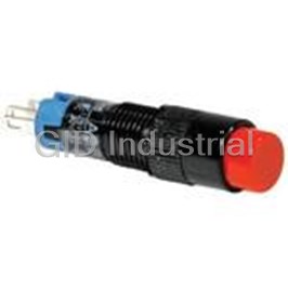
IDEC CORPORATION LA1P-1C04-R

Description
Miniature Control Units
LA1P-1C04-R
Part Number
LA1P-1C04-R
Price
Request Quote
Manufacturer
IDEC CORPORATION
Lead Time
Request Quote
Category
Thermal Management » Misc Products
Specifications
Manufacturer
IDEC Corporation
Manufacturers Part #
LA1P-1C04-R
Sub-Categories
Miscellaneous Tools and Supplies
Factory Pack Quantity
1
Datasheet

Extracted Text
ş16mm
L6 Series
Miniature Control Units
(07/02/08)
ş16 L6 Series Miniature Control Units
Series L6 Series Miniature Control Units
Mounting Hole Size ş16
Type LA�L/LA�PLA�B LA1T LA�S
Appearance
Illuminated Pushbuttons Pushbuttons Lever Switches Selector Switches
(momentary, maintained) (momentary, maintained) (2-position maintained) (2-position maintained)
(2-position spring return) (2-position spring return)
Pilot Lights
(3-position maintained) (3-position maintained)
Unit
(3-position spring return) (3-position spring return)
Bezel Size ş18 �18 18 × 24 ş18 �18 18 × 24 ş18 ş18 �18 18 × 24
Bezel Color Black
LED Lamp
Light Source ———
(IDEC’s LFTD type)
Lens: amber, blue, green, Button: black, blue, green,
Lens/Button Color Lever: black Knob: black
white, red, yellow red, white, yellow
Contact
SPDT, DPDT (gold-clad silver contact, silver contact)
ConŢguration
Contact Rating 125V AC/0.1A, 30V DC/0.1A (gold-clad silver contact)
(resistive load) 125V AC/5A, 30V DC/3A (silver contact)
Momentary:100,000 operations minimum 100,000 operations 100,000 operations
Electrical
Maintained: 100,000 operations minimum minimum minimum
Momentary: 2,000,000 operations minimum 250,000 operations 250,000 operations
Mechanical
Maintained: 250,000 operations minimum minimum minimum
Degree of Protection IP65 (IEC 60529)
Solder/tab terminal #110
Terminal Style
PC board terminal (gold contacts only)
Switch Guard Yes Yes — —
Socket ————
Terminal Cover Yes Yes Yes Yes
Dust Cover Yes Yes — —
Mounting Hole Plug Yes Yes Yes Yes
Approvals
Page 5 8 10 12
2 (07/02/08)
Accessories Durability Contact
L6 Series Miniature Control Units ş16
L6 Series Miniature
Series L6 Series Miniature Control Units Series
Control Units
Mounting Hole Size ş16 Mounting Hole Size ş16
Type LA�KLA�F Type LA3Z
Appearance Appearance
Key Selector Switches Illuminated Selector Buzzer
(2-position maintained) Switches
(2-position spring return) (2-position maintained)
(3-position maintained) (2-position spring return)
Unit Unit
(3-position spring return) (3-position maintained)
(3-position spring return)
Bezel Size ş18 �18 18 × 24 Bezel Size 18 × 24
Bezel Color Black Bezel Color Black
LED lamp Operating Voltage 6V AC/DC
Light Source —
(IDEC’s LFTD type) (±10%) 12V to 24V AC/DC
Sound Pressure Steady sound: 80 dB mini-
Illumination color:
Key cylinder:
(at 0.1m) mum (at the rated voltage)
Lens/Button Color amber, blue, green, red,
chrome-plated (metal)
white, yellow
Sound Frequency 2 kHz ±500 Hz
Contact
Slow intermittent sound:
SPDT, DPDT (gold-clad silver contact, silver contact)
ConŢguration
55 cycles per minute ±10%
Sound Cycle
Quick intermittent sound:
Contact Rating 125V AC/0.1A, 30V DC/0.1A (gold-clad silver contact)
600 cycles per minute ±10%
(resistive load) 125V AC/5A, 30V DC/3A (silver contact)
Degree of Protection IP40 (enclosed type)
Electrical 100,000 operations minimum
Terminal Style Solder/tab terminal #110
Switch Guard —
Mechanical 250,000 operations minimum
Socket —
Degree of Protection IP65 (IEC 60529)
Terminal Cover Yes
Solder/tab terminal #110
Terminal Style
PC board terminal (gold contacts only) Dust Cover —
Switch Guard — —
Mounting Hole Plug Yes
Socket — —
• Continuous, intermittent
Terminal Cover Yes Yes (slow), intermittent (quick)
sounds can be selected
Dust Cover — — Remarks
with a built-in slide switch.
Mounting Hole Plug Yes Yes
• PC board terminals also
available.
Approvals
Approvals —
Page 13 16 Page 20
(07/02/08) 3
Accessories Durability Contact
Accessories Ratings
ş16 L6 Series Miniature Control Units
Light duty L6 series
Suitable for electronic devices and for food processing and packaging industries.
• Locking lever removable contact blocks
• Bright and clear LED illumination
• Gold-clad cross bar contacts and silver contacts
• Degree of protection: IP65 (IEC 60529)
(except buzzers)
• UL recognized and CSA certiŢed
(except buzzers)
• EN compliant (except buzzers)
(EN60947-1, EN60947-5-1, TÜV Rheinland)
• RoHS compliant
SpeciŢcations and Ratings
˙
Contact Ratings SpeciŢcations
Operating Temperature –25 to +55°C (no freezing)
• Gold Contact
Storage Temperature –30 to +80°C
Maximum Voltage 250V AC/DC
Operating Humidity 45 to 85% RH (no condensation)
Thermal Current 3A
Contact Resistance 50 mΩ maximum (initial value)
Operating Voltage 125V AC 30V DC
Insulation Resistance 100 MΩ minimum (500V DC megger)
Operating Current
0.1A 0.1A
(resistive load)
Between live part and ground:
2,500V AC, 1 minute
Contact Material Gold-clad silver
Between terminals of different poles:
Switch Unit
Minimum applicable load (reference value): 5V AC/DC, 1 mA
2,500V AC, 1 minute
Dielectric
(Applicable range is subject to the operating condition and load.)
Between terminals of the same poles:
Strength
1,000V AC, 1 minute
• Silver Contact
Illumination Between live part and ground:
Insulation Voltage 250V
Unit 2,500V AC, 1 minute
Operating Voltage 30V 125V 250V
Operating extremes:
Vibration Resistance
5 to 55 Hz, amplitude 0.5 mm
Resistive Load — 5A 2A
AC
2
50/60Hz Damage limits: 1,000 m/s (100G)
Inductive Load — 2A 1.5A
Operating Shock Resistance
2
Operating extremes: 100 m/s (10G)
Current
Resistive Load 3A 0.4A —
DC Momentary: 2,000,000
Inductive Load 1A 0.2A —
Maintained: 250,000
Mechanical Durability Lever switches: 250,000
Thermal Current 5A
(minimum operations) Selector switches: 250,000
Contact Material Silver
Key selector switches 250,000
Illuminated selector switches: 250,000
AC inductive load: PF = 0.6 to 0.7
DC inductive load: L/R = 7 ms maximum
Momentary: 100,000 (∗1, ∗3)
Maintained: 100,000 (∗2, ∗3)
Lever switches: 100,000 (∗2, ∗3)
Built-in LED Lamp Ratings Selector switches: 100,000 (∗2, ∗3)
Electrical Durability Key selector switches: 100,000 (∗2, ∗3)
Type No. LFTD-5 LFTD-1 LFTD-2
➁ ➁ ➁ (minimum operations) Illuminated selector switches: 100,000 (∗2, ∗3)
∗1 Switching frequency 1,800 operations/h
Lamp Base SX6S/8×5.4
∗2 Switching frequency 1,200 operations/h
Rated Voltage 5V DC 12V AC/DC 24V AC/DC ∗3 125V resistive load 5A: 50,000
3A: 100,000
Operating
5V DC ±5% 12V AC/DC ±10% 24V AC/DC ±10%
Degree of Protection IP65 (IEC 60529)
Voltage
Solder/tab terminal #110
AC — 9 mA 9 mA Terminal Style
Current
PC board terminal
Draw
DC 8 mA 8 mA 8 mA
17g (LA1L-M1C24)
Specify a color code in place of in the Type No.
➁
15g (LA1P-1C04)
Color Code A (amber), G (green), R (red), S (blue), W (white),
➁
13g (LA1B-M1C2)
Y (yellow)
Weight (approx.) 15g (LA1T-2C2)
Lamp Base
Same as illumination color
15g (LA1S-2C2)
Color
27g (LA1K-2C2A)
Voltage Marking Die stamped on the lamp base
18g (LA1F-2C24)
Approx. 50,000 hours
Life
(When used on complete DC, luminance reduces to 50%
(reference value)
of the initial intensity.)
A, R, W, Y A, R, W, Y
(+) (–)
Internal
Circuit
G, S G, S
LED Chip
(+) (–)
Protection Diode
Zener Diode
4 (07/02/08)
L6 Series Miniature Control Units ş16
LA1L / LA2L Illuminated Pushbuttons
Type No.
Operation Contact Operating Lens Color
➁
Shape Contact
Solder/Tab PC Board
Type Material Voltage Code
Terminal Terminal
Round SPDT LA1L-M1C11➁ LA1L-M1C11V➁
5V DC ±5%
LA1L
DPDT LA1L-M1C21➁ LA1L-M1C21V➁
SPDT LA1L-M1C13➁ LA1L-M1C13V➁
Gold 12V AC/DC ±10%
DPDT LA1L-M1C23➁ LA1L-M1C23V➁
SPDT LA1L-M1C14➁ LA1L-M1C14V➁
24V AC/DC ±10%
DPDT LA1L-M1C24➁ LA1L-M1C24V➁
Momentary
SPDT LA1L-M1C51➁ —
5V DC ±5%
DPDT LA1L-M1C61➁ —
SPDT LA1L-M1C53➁ —
Silver 12V AC/DC ±10%
DPDT LA1L-M1C63➁ —
SPDT LA1L-M1C54➁ —
24V AC/DC ±10%
DPDT LA1L-M1C64➁ —
SPDT LA1L-A1C11➁ LA1L-A1C11V➁
5V DC ±5%
DPDT LA1L-A1C21➁ LA1L-A1C21V➁
SPDT LA1L-A1C13➁ LA1L-A1C13V➁
Gold 12V AC/DC ±10%
DPDT LA1L-A1C23➁ LA1L-A1C23V➁
SPDT LA1L-A1C14➁ LA1L-A1C14V➁
24V AC/DC ±10%
DPDT LA1L-A1C24➁ LA1L-A1C24V➁
Maintained
SPDT LA1L-A1C51➁ —
5V DC ±5%
DPDT LA1L-A1C61➁ —
Specify a lens
SPDT LA1L-A1C53➁ —
color code in
Silver 12V AC/DC ±10%
DPDT LA1L-A1C63➁ —
place of in the
➁
Type No.
SPDT LA1L-A1C54➁ —
24V AC/DC ±10%
DPDT LA1L-A1C64➁ —
A: amber
Square SPDT LA2L-M1C11➁ LA2L-M1C11V➁
G: green
5V DC ±5%
LA2L
DPDT LA2L-M1C21➁ LA2L-M1C21V➁ R: red
W: white
SPDT LA2L-M1C13➁ LA2L-M1C13V➁
Gold 12V AC/DC ±10%
S: blue
DPDT LA2L-M1C23➁ LA2L-M1C23V➁
Y: yellow
SPDT LA2L-M1C14➁ LA2L-M1C14V➁
24V AC/DC ±10%
DPDT LA2L-M1C24➁ LA2L-M1C24V➁
Momentary
SPDT LA2L-M1C51➁ —
5V DC ±5%
DPDT LA2L-M1C61➁ —
SPDT LA2L-M1C53➁ —
Silver 12V AC/DC ±10%
DPDT LA2L-M1C63➁ —
SPDT LA2L-M1C54➁ —
24V AC/DC ±10%
DPDT LA2L-M1C64➁ —
SPDT LA2L-A1C11➁ LA2L-A1C11V➁
5V DC ±5%
DPDT LA2L-A1C21➁ LA2L-A1C21V➁
SPDT LA2L-A1C13➁ LA2L-A1C13V➁
Gold 12V AC/DC ±10%
DPDT LA2L-A1C23➁ LA2L-A1C23V➁
SPDT LA2L-A1C14➁ LA2L-A1C14V➁
24V AC/DC ±10%
DPDT LA2L-A1C24➁ LA2L-A1C24V➁
Maintained
SPDT LA2L-A1C51➁ —
5V DC ±5%
DPDT LA2L-A1C61➁ —
SPDT LA2L-A1C53➁ —
Silver 12V AC/DC ±10%
DPDT LA2L-A1C63➁ —
SPDT LA2L-A1C54➁ —
24V AC/DC ±10%
DPDT LA2L-A1C64➁ —
L-shaped lever contact types are also available for collective mounting.
To order L-shaped lever contacts, specify “T” in place of “C” in the Type No.
(Standard contact type) (L-shaped lever contact type)
Example: LA1L-M1C11 LA1L-M1T11
➁ ➁
(07/02/08) 5
ş16 L6 Series Miniature Control Units
LA3L / LA4L Illuminated Pushbuttons
Type No.
Operation Contact Operating Lens Color
➁
Shape Contact
Solder/Tab PC Board
Type Material Voltage Code
Terminal Terminal
Rectangular SPDT LA3L-M1C11➁ LA3L-M1C11V➁
5V DC ±5%
LA3L
DPDT LA3L-M1C21➁ LA3L-M1C21V➁
SPDT LA3L-M1C13➁ LA3L-M1C13V➁
Gold 12V AC/DC ±10%
DPDT LA3L-M1C23➁ LA3L-M1C23V➁
SPDT LA3L-M1C14➁ LA3L-M1C14V➁
24V AC/DC ±10%
DPDT LA3L-M1C24➁ LA3L-M1C24V➁
Momentary
SPDT LA3L-M1C51➁ —
5V DC ±5%
DPDT LA3L-M1C61➁ —
SPDT LA3L-M1C53➁ —
Silver 12V AC/DC ±10%
DPDT LA3L-M1C63➁ —
SPDT LA3L-M1C54➁ —
24V AC/DC ±10%
DPDT LA3L-M1C64➁ —
SPDT LA3L-A1C11➁ LA3L-A1C11V➁
5V DC ±5%
DPDT LA3L-A1C21➁ LA3L-A1C21V➁
SPDT LA3L-A1C13➁ LA3L-A1C13V➁
Gold 12V AC/DC ±10%
DPDT LA3L-A1C23➁ LA3L-A1C23V➁
SPDT LA3L-A1C14➁ LA3L-A1C14V➁
24V AC/DC ±10%
DPDT LA3L-A1C24➁ LA3L-A1C24V➁
Maintained
SPDT LA3L-A1C51➁ —
5V DC ±5%
DPDT LA3L-A1C61➁ —
Specify a lens
SPDT LA3L-A1C53➁ —
color code in
Silver 12V AC/DC ±10%
DPDT LA3L-A1C63➁ —
place of in the
➁
Type No.
SPDT LA3L-A1C54➁ —
24V AC/DC ±10%
DPDT LA3L-A1C64➁ —
A: amber
Rectangular SPDT LA4L-M1C11➁ LA4L-M1C11V➁
G: green
5V DC ±5%
3-sided Barrier
DPDT LA4L-M1C21➁ LA4L-M1C21V➁ R: red
LA4L
W: white
SPDT LA4L-M1C13➁ LA4L-M1C13V➁
Gold 12V AC/DC ±10%
S: blue
DPDT LA4L-M1C23➁ LA4L-M1C23V➁
Y: yellow
SPDT LA4L-M1C14➁ LA4L-M1C14V➁
24V AC/DC ±10%
DPDT LA4L-M1C24➁ LA4L-M1C24V➁
Momentary
SPDT LA4L-M1C51➁ —
5V DC ±5%
DPDT LA4L-M1C61➁ —
SPDT LA4L-M1C53➁ —
Silver 12V AC/DC ±10%
DPDT LA4L-M1C63➁ —
SPDT LA4L-M1C54➁ —
24V AC/DC ±10%
DPDT LA4L-M1C64➁ —
SPDT LA4L-A1C11➁ LA4L-A1C11V➁
5V DC ±5%
DPDT LA4L-A1C21➁ LA4L-A1C21V➁
SPDT LA4L-A1C13➁ LA4L-A1C13V➁
Gold 12V AC/DC ±10%
DPDT LA4L-A1C23➁ LA4L-A1C23V➁
SPDT LA4L-A1C14➁ LA4L-A1C14V➁
24V AC/DC ±10%
DPDT LA4L-A1C24➁ LA4L-A1C24V➁
Maintained
SPDT LA4L-A1C51➁ —
5V DC ±5%
DPDT LA4L-A1C61➁ —
SPDT LA4L-A1C53➁ —
Silver 12V AC/DC ±10%
DPDT LA4L-A1C63➁ —
SPDT LA4L-A1C54➁ —
24V AC/DC ±10%
DPDT LA4L-A1C64➁ —
L-shaped lever contact types are also available for collective mounting.
To order L-shaped lever contact types, specify “T” in place of “C” in the Type No.
(Standard contact type) (L-shaped lever contact type)
Example: LA3L-M1C11 LA3L-M1T11
➁ ➁
6 (07/02/08)
L6 Series Miniature Control Units ş16
LA�P Pilot Lights
Type No.
Shape Operating Voltage ➁ Lens Color Code
Solder/Tab Terminal PC Board Terminal
Round
LA1P
5V DC ±5% LA1P-1C01➁ LA1P-1C01V➁
12V AC/DC ±10% LA1P-1C03➁ LA1P-1C03V➁
24V AC/DC ±10% LA1P-1C04➁ LA1P-1C04V➁
Square
LA2P
5V DC ±5% LA2P-1C01➁ LA2P-1C01V➁
12V AC/DC ±10% LA2P-1C03➁ LA2P-1C03V➁
Specify a lens color code in
place of ➁ in the Type No.
24V AC/DC ±10% LA2P-1C04➁ LA2P-1C04V➁
A: amber
G: green
Rectangular
R: red
LA3P
W: white
5V DC ±5% LA3P-1C01➁ LA3P-1C01V➁
S: blue
Y: yellow
12V AC/DC ±10% LA3P-1C03➁ LA3P-1C03V➁
24V AC/DC ±10% LA3P-1C04➁ LA3P-1C04V➁
Rectangular 3-sided Barrier
LA4P
5V DC ±5% LA4P-1C01➁ LA4P-1C01V➁
12V AC/DC ±10% LA4P-1C03➁ LA4P-1C03V➁
24V AC/DC ±10% LA4P-1C04➁ LA4P-1C04V➁
L-shaped lever contact types are also available for collective mounting.
To order L-shaped lever contact types, specify “T” in place of “C” in the Type No.
(Standard contact type) (L-shaped lever contact type)
Example: LA1P-1C01➁ LA1P-1T01➁
(07/02/08) 7
ş16 L6 Series Miniature Control Units
LA1B / LA2B Pushbuttons
Type No.
Operation Contact
Shape Button Type Contact Color Code➀➁
Solder/Tab PC Board
Type Material
Terminal Terminal
Round SPDT LA1B-M1C1➀ LA1B-M1C1V➀
Gold
LA1B
DPDT LA1B-M1C2➀ LA1B-M1C2V➀
B: black
Momentary
SPDT LA1B-M1C5➀ —
G: green
Silver
DPDT LA1B-M1C6➀ —
R: red
Button
S: blue
SPDT LA1B-A1C1➀ LA1B-A1C1V➀
Gold
W: white
DPDT LA1B-A1C2➀ LA1B-A1C2V➀
Maintained Y: yellow
SPDT LA1B-A1C5➀ —
Silver
DPDT LA1B-A1C6➀ —
SPDT LA1B-M1C1L➁ LA1B-M1C1VL➁
Gold
DPDT LA1B-M1C2L➁ LA1B-M1C2VL➁
A: amber
Momentary
SPDT LA1B-M1C5L➁ —
G: green
Silver
DPDT LA1B-M1C6L➁ —
R: red
Illumination Lens
S: blue
SPDT LA1B-A1C1L➁ LA1B-A1C1VL➁
Gold
W: white
DPDT LA1B-A1C2L➁ LA1B-A1C2VL➁
Maintained Y: yellow
SPDT LA1B-A1C5L➁ —
Silver
DPDT LA1B-A1C6L➁ —
Square SPDT LA2B-M1C1➀ LA2B-M1C1V➀
Gold
LA2B
DPDT LA2B-M1C2➀ LA2B-M1C2V➀
B: black
Momentary
SPDT LA2B-M1C5➀ —
G: green
Silver
DPDT LA2B-M1C6➀ —
R: red
Button
S: blue
SPDT LA2B-A1C1➀ LA2B-A1C1V➀
Gold
W: white
DPDT LA2B-A1C2➀ LA2B-A1C2V➀
Maintained Y: yellow
SPDT LA2B-A1C5➀ —
Silver
DPDT LA2B-A1C6➀ —
SPDT LA2B-M1C1L➁ LA2B-M1C1VL➁
Gold
DPDT LA2B-M1C2L➁ LA2B-M1C2VL➁
A: amber
Momentary
SPDT LA2B-M1C5L➁ —
G: green
Silver
DPDT LA2B-M1C6L➁ —
R: red
Illumination Lens
S: blue
SPDT LA2B-A1C1L➁ LA2B-A1C1VL➁
Gold
W: white
DPDT LA2B-A1C2L➁ LA2B-A1C2VL➁
Maintained Y: yellow
SPDT LA2B-A1C5L➁ —
Silver
DPDT LA2B-A1C6L➁ —
L-shaped lever contact types are also available for collective mounting.
To order L-shaped lever contact types, specify “T” in place of “C” in the Type No.
(Standard contact type) (L-shaped lever contact type)
Example: LA1B-M1C1➀ LA1B-M1T1➀
8 (07/02/08)
L6 Series Miniature Control Units ş16
LA3B / LA4B Pushbuttons
Type No.
Operation Contact
Shape Button Type Contact Color Code➀➁
Solder/Tab PC Board
Type Material
Terminal Terminal
Rectangular SPDT LA3B-M1C1➀ LA3B-M1C1V➀
Gold
LA3B
DPDT LA3B-M1C2➀ LA3B-M1C2V➀
B: black
Momentary
SPDT LA3B-M1C5➀ —
G: green
Silver
DPDT LA3B-M1C6➀ —
R: red
Button
S: blue
SPDT LA3B-A1C1➀ LA3B-A1C1V➀
Gold
W: white
DPDT LA3B-A1C2➀ LA3B-A1C2V➀
Maintained Y: yellow
SPDT LA3B-A1C5➀ —
Silver
DPDT LA3B-A1C6➀ —
SPDT LA3B-M1C1L➁ LA3B-M1C1VL➁
Gold
DPDT LA3B-M1C2L➁ LA3B-M1C2VL➁
A: amber
Momentary
SPDT LA3B-M1C5L➁ —
G: green
Silver
DPDT LA3B-M1C6L➁ —
R: red
Illumination Lens
S: blue
SPDT LA3B-A1C1L➁ LA3B-A1C1VL➁
Gold
W: white
DPDT LA3B-A1C2L➁ LA3B-A1C2VL➁
Maintained Y: yellow
SPDT LA3B-A1C5L➁ —
Silver
DPDT LA3B-A1C6L➁ —
Rectangular SPDT LA4B-M1C1➀ LA4B-M1C1V➀
Gold
3-sided Barrier
DPDT LA4B-M1C2➀ LA4B-M1C2V➀
B: black
Momentary
LA4B
SPDT LA4B-M1C5➀ —
G: green
Silver
DPDT LA4B-M1C6➀ —
R: red
Button
S: blue
SPDT LA4B-A1C1➀ LA4B-A1C1V➀
Gold
W: white
DPDT LA4B-A1C2➀ LA4B-A1C2V➀
Maintained Y: yellow
SPDT LA4B-A1C5➀ —
Silver
DPDT LA4B-A1C6➀ —
SPDT LA4B-M1C1L➁ LA4B-M1C1VL➁
Gold
DPDT LA4B-M1C2L➁ LA4B-M1C2VL➁
A: amber
Momentary
SPDT LA4B-M1C5L➁ —
G: green
Silver
DPDT LA4B-M1C6L➁ —
R: red
Illumination Lens
S: blue
SPDT LA4B-A1C1L➁ LA4B-A1C1VL➁
Gold
W: white
DPDT LA4B-A1C2L➁ LA4B-A1C2VL➁
Maintained Y: yellow
SPDT LA4B-A1C5L➁ —
Silver
DPDT LA4B-A1C6L➁ —
L-shaped lever contact types are also available for collective mounting.
To order L-shaped lever contact types, specify “T” in place of “C” in the Type No.
(Standard contact type) (L-shaped lever contact type)
Example: LA3B-M1C1➀ LA3B-M1T1➀
(07/02/08) 9
ş16 L6 Series Miniature Control Units
LA1T Lever Switches
Type No.
Contact
Shape Lever Operation Contact
Solder/Tab PC Board
Material
Terminal Terminal
Round Maintained SPDT LA1T-2C1 LA1T-2C1V
Gold
LA1T
U
DPDT LA1T-2C2 LA1T-2C2V
SPDT LA1T-2C5 —
Silver
D
DPDT LA1T-2C6 —
Spring return from top SPDT LA1T-21C1 LA1T-21C1V
Gold
U
DPDT LA1T-21C2 LA1T-21C2V
2-position
SPDT LA1T-21C5 —
D Silver
DPDT LA1T-21C6 —
Spring return from bottom SPDT LA1T-22C1 LA1T-22C1V
Gold
U
DPDT LA1T-22C2 LA1T-22C2V
SPDT LA1T-22C5 —
D
Silver
DPDT LA1T-22C6 —
U
Maintained
Gold DPDT LA1T-3C2 LA1T-3C2V
C
Silver DPDT LA1T-3C6 —
D
U
Spring return from top
Gold DPDT LA1T-31C2 LA1T-31C2V
C
Silver DPDT LA1T-31C6 —
D
3-position
U
Spring return from bottom
Gold DPDT LA1T-32C2 LA1T-32C2V
C
Silver DPDT LA1T-32C6 —
D
U
Spring return two-way
Gold DPDT LA1T-33C2 LA1T-33C2V
C
Silver DPDT LA1T-33C6 —
D
L-shaped lever contact types are also available for collective mounting.
To order L-shaped lever contact types, specify “T” in place of “C” in the Type No.
(Standard contact type) (L-shaped lever contact type)
Example: LA1T-2C1 LA1T-2T1
Contact Operation
Operator Position & Contact Operation (Top View)
Contact Down Center Up
NO NC NO NC
SPDT —
C C
90° 2-position
Maintained
Left Right
Left Right
Spring return from top Contact Contact
Contact Contact
NO NC NO NC
NO NC NO NC
DPDT —
C C
C C
NO NC
NO NC
SPDT —
C C
90° 2-position
Spring return from bottom
Right Left Right
Left
Contact Contact
Contact Contact
NO NC NO NC
NO NC NO NC
DPDT —
C C
C C
Left Right
Left Right Left Right
Contact Contact Contact Contact
Contact Contact
NO NC NO NC NO NC NO NC
NO NC NO NC
45° 3-position DPDT
C C
C C C C
10 (07/02/08)
LOCK
TOP
LOCK
L6 Series Miniature Control Units ş16
Dimensions
Pilot Lights Pushbuttons
Illuminated Pushbuttons
Panel Thickness 0.5 to 6 Note:
Gasket
5.7
1. Pushbuttons do not have lamp terminals.
Locking Ring
2. Pilot lights have only lamp terminals.
3. See page 26 for L-shaped lever contact
types.
Anti-rotation Ring 0.6
Rectangular
Tab Terminal Width 2.8×0.5t
R15.5 PC Board Terminal Round Square Rectangular 3-sided Barrier
Width 0.8×0.5t
1 2.6
2
10.5 13.5 24 24
18
17.8
5.5
936 9
PC Board Terminal Solder/Tab Terminal
Lever Switches
10.8
24
Mounting Hole Layout
Standard Contact Type
+0.2
ø16.2 0
Note: Determine mounting centers to ensure easy operation.
• See page 26 for L-shaped lever contact types.
24
Terminal Arrangement (Bottom View)
Pushbuttons
Illuminated Pushbuttons Pilot Lights
Lever Switches
TOP TOP TOP
Lamp Terminal Lamp Terminal
(+) (+)
Lamp Terminal Lamp Terminal
(−) (−)
SPDT has C, NO, and NC only on the right. X2 terminals are interconnected. SPDT has C, NO, and NC
X2 terminals are interconnected. only on the right.
PC Board Drilling Layout (Bottom View)
Pushbuttons
Illuminated Pushbuttons Pilot Lights
Lever Switches
7.85 6.8
6.4 6.8
1.45 1.45
All dimensions in mm.
• See One Board Mounting on page 26 for details about PC boards.
(07/02/08) 11
ş18
ø18
ş1.2 Hole
ş1.2 Hole
ş1.2 Hole
ş21
15.8
7.85
24
X2 X2 X1
C NO NC
C NO NC
X2 X2 X1
6.8
5 5
1.45
CN NOC 1
1
5 5
CN NOC
6 6
6.8 6.4
1.2
1 1.45
X2 X2 X1
1
5 5
CN NOC
1
CN NOC
5 5
18
ş16
L6 Series Miniature Control Units
LA�S Selector Switches
Type No.
Contact
Shape Position Contact
Solder/Tab PC Board
Material
Terminal Terminal
Round SPDT LA1S-2C1 LA1S-2C1V
Gold
LA1S
L R DPDT LA1S-2C2 LA1S-2C2V
Maintained
SPDT LA1S-2C5 —
Silver
DPDT LA1S-2C6 —
90° 2-position
SPDT LA1S-21C1 LA1S-21C1V
Gold
L R
DPDT LA1S-21C2 LA1S-21C2V
Spring return
from right
SPDT LA1S-21C5 —
Silver
DPDT LA1S-21C6 —
C
Gold DPDT LA1S-3C2 LA1S-3C2V
L R
Maintained
Silver DPDT LA1S-3C6 —
C
Gold DPDT LA1S-31C2 LA1S-31C2V
Spring return L R
from right
Silver DPDT LA1S-31C6 —
45° 3-position
C
Gold DPDT LA1S-32C2 LA1S-32C2V
Spring return L R
from left
Silver DPDT LA1S-32C6 —
C
Gold DPDT LA1S-33C2 LA1S-33C2V
Spring return L R
two-way
Silver DPDT LA1S-33C6 —
Square SPDT LA2S-2C1 LA2S-2C1V
Gold
LA2S
L R DPDT LA2S-2C2 LA2S-2C2V
Maintained
SPDT LA2S-2C5 —
Silver
DPDT LA2S-2C6 —
90° 2-position
SPDT LA2S-21C1 LA2S-21C1V
Gold
L R
DPDT LA2S-21C2 LA2S-21C2V
Spring return
from right
SPDT LA2S-21C5 —
Silver
DPDT LA2S-21C6 —
C
Gold DPDT LA2S-3C2 LA2S-3C2V
L R
Maintained
Silver DPDT LA2S-3C6 —
C
Gold DPDT LA2S-31C2 LA2S-31C2V
Spring return L R
from right
Silver DPDT LA2S-31C6 —
45° 3-position
C
Gold DPDT LA2S-32C2 LA2S-32C2V
Spring return L R
from left
Silver DPDT LA2S-32C6 —
C
Gold DPDT LA2S-33C2 LA2S-33C2V
Spring return L R
two-way
Silver DPDT LA2S-33C6 —
Rectangular SPDT LA3S-2C1 LA3S-2C1V
Gold
LA3S
L R DPDT LA3S-2C2 LA3S-2C2V
Maintained
SPDT LA3S-2C5 —
Silver
DPDT LA3S-2C6 —
90° 2-position
SPDT LA3S-21C1 LA3S-21C1V
Gold
L R
DPDT LA3S-21C2 LA3S-21C2V
Spring return
from right
SPDT LA3S-21C5 —
Silver
DPDT LA3S-21C6 —
C
Gold DPDT LA3S-3C2 LA3S-3C2V
L R
Maintained
Silver DPDT LA3S-3C6 —
C
Gold DPDT LA3S-31C2 LA3S-31C2V
Spring return L R
from right
Silver DPDT LA3S-31C6 —
45° 3-position
C
Gold DPDT LA3S-32C2 LA3S-32C2V
Spring return L R
from left
Silver DPDT LA3S-32C6 —
C
Gold DPDT LA3S-33C2 LA3S-33C2V
Spring return L R
two-way
Silver DPDT LA3S-33C6 —
• For contact operation, see page 19.
• L-shaped lever contact types are also available for collective mounting.
To order L-shaped contact types, specify “T” in place of “C” in the Type No.
(Standard contact type) (L-shaped lever contact type)
Example: LA1S-2C1 LA1S-2T1
12 (07/02/08)
L6 Series Miniature Control Units ş16
LA1K Key Selector Switches
Type No.
Key Retained Contact
Shape Position Contact
Solder/Tab PC Board
at ���� Material
Terminal Terminal
Round SPDT LA1K-2C1A LA1K-2C1VA
Gold
LA1K
LR DPDT LA1K-2C2A LA1K-2C2VA
A
SPDT LA1K-2C5A —
Silver
DPDT LA1K-2C6A —
SPDT LA1K-2C1B LA1K-2C1VB
Gold
L R DPDT LA1K-2C2B LA1K-2C2VB
Maintained B
SPDT LA1K-2C5B —
Silver
DPDT LA1K-2C6B —
90° 2-position
SPDT LA1K-2C1C LA1K-2C1VC
Gold
L L R DPDT LA1K-2C2C LA1K-2C2VC
C
SPDT LA1K-2C5C —
Silver
DPDT LA1K-2C6C —
SPDT LA1K-21C1B LA1K-21C1VB
Silver
L R
DPDT LA1K-21C2B LA1K-21C2VB
Spring return
B
from right
SPDT LA1K-21C5B —
Gold
DPDT LA1K-21C6B —
C
Gold DPDT LA1K-3C2A LA1K-3C2VA
L
R
A
Silver DPDT LA1K-3C6A —
C
Gold DPDT LA1K-3C2B LA1K-3C2VB
L
R
B
Silver DPDT LA1K-3C6B —
C
Gold DPDT LA1K-3C2C LA1K-3C2VC
L
R
C
Silver DPDT LA1K-3C6C —
C
Gold DPDT LA1K-3C2D LA1K-3C2VD
L
R
Maintained
D
Silver DPDT LA1K-3C6D —
C
Gold DPDT LA1K-3C2E LA1K-3C2VE
L
R
E
Silver DPDT LA1K-3C6E —
C
Gold DPDT LA1K-3C2G LA1K-3C2VG
L
R
G
Silver DPDT LA1K-3C6G —
C
Gold DPDT LA1K-3C2H LA1K-3C2VH
L
R
H
Silver DPDT LA1K-3C6H —
45° 3-position
C
Gold DPDT LA1K-31C2B LA1K-31C2VB
L
R
B
Silver DPDT LA1K-31C6B —
C
Gold DPDT LA1K-31C2D LA1K-31C2VD
Spring return L
R
D
from right
Silver DPDT LA1K-31C6D —
C
Gold DPDT LA1K-31C2G LA1K-31C2VG
L
R
G
Silver DPDT LA1K-31C6G —
C
Gold DPDT LA1K-32C2C LA1K-32C2VC
L
R
C
Silver DPDT LA1K-32C6C —
C
Gold DPDT LA1K-32C2D LA1K-32C2VD
Spring return L
R
D
from left
Silver DPDT LA1K-32C6D —
C
Gold DPDT LA1K-32C2H LA1K-32C2VH
L
R
H
Silver DPDT LA1K-32C6H —
C
Gold DPDT LA1K-33C2D LA1K-33C2VD
Spring return L
R
D
two-way
Silver DPDT LA1K-33C6D —
• For contact operation, see page 19.
• Two keys are supplied.
• L-shaped lever contact types are also available for collective mounting.
To order L-shaped contact types, specify “T” in place of “C” in the Type No.
(Standard contact type) (L-shaped lever contact type)
Example: LA1K-2C1A LA1K-2T1A
(07/02/08) 13
ş16
L6 Series Miniature Control Units
LA2K Key Selector Switches
Type No.
Key Retained Contact
Shape Position Contact
Solder/Tab PC Board
at ���� Material
Terminal Terminal
Square SPDT LA2K-2C1A LA2K-2C1VA
Gold
LA2K
DPDT LA2K-2C2A LA2K-2C2VA
LR
A
SPDT LA2K-2C5A —
Silver
DPDT LA2K-2C6A —
SPDT LA2K-2C1B LA2K-2C1VB
Gold
DPDT LA2K-2C2B LA2K-2C2VB
L R
Maintained B
SPDT LA2K-2C5B —
Silver
DPDT LA2K-2C6B —
90° 2-position
SPDT LA2K-2C1C LA2K-2C1VC
Gold
L L R DPDT LA2K-2C2C LA2K-2C2VC
C
SPDT LA2K-2C5C —
Silver
DPDT LA2K-2C6C —
SPDT LA2K-21C1B LA2K-21C1VB
Silver
L R
DPDT LA2K-21C2B LA2K-21C2VB
Spring return
B
from right
SPDT LA2K-21C5B —
Gold
DPDT LA2K-21C6B —
C
Gold DPDT LA2K-3C2A LA2K-3C2VA
L
R
A
Silver DPDT LA2K-3C6A —
C
Gold DPDT LA2K-3C2B LA2K-3C2VB
L
R
B
Silver DPDT LA2K-3C6B —
C
Gold DPDT LA2K-3C2C LA2K-3C2VC
L
R
C
Silver DPDT LA2K-3C6C —
C
Gold DPDT LA2K-3C2D LA2K-3C2VD
L
R
Maintained
D
Silver DPDT LA2K-3C6D —
C
Gold DPDT LA2K-3C2E LA2K-3C2VE
L
R
E
Silver DPDT LA2K-3C6E —
C
Gold DPDT LA2K-3C2G LA2K-3C2VG
L
R
G
Silver DPDT LA2K-3C6G —
C
Gold DPDT LA2K-3C2H LA2K-3C2VH
L
R
H
Silver DPDT LA2K-3C6H —
45° 3-position
C
Gold DPDT LA2K-31C2B LA2K-31C2VB
L
R
B
Silver DPDT LA2K-31C6B —
C
Gold DPDT LA2K-31C2D LA2K-31C2VD
Spring return L
R
D
from right
Silver DPDT LA2K-31C6D —
C
Gold DPDT LA2K-31C2G LA2K-31C2VG
L
R
G
Silver DPDT LA2K-31C6G —
C
Gold DPDT LA2K-32C2C LA2K-32C2VC
L
R
C
Silver DPDT LA2K-32C6C —
C
Gold DPDT LA2K-32C2D LA2K-32C2VD
Spring return L
R
D
from left
Silver DPDT LA2K-32C6D —
C
Gold DPDT LA2K-32C2H LA2K-32C2VH
L
R
H
Silver DPDT LA2K-32C6H —
C
Gold DPDT LA2K-33C2D LA2K-33C2VD
Spring return L
R
D
two-way
Silver DPDT LA2K-33C6D —
• For contact operation, see page 19.
• Two keys are supplied.
• L-shaped lever contact types are also available for collective mounting.
To order L-shaped contact types, specify “T” in place of “C” in the Type No.
(Standard contact type) (L-shaped lever contact type)
Example: LA2K-2C1A LA2K-2T1A
14 (07/02/08)
L6 Series Miniature Control Units ş16
LA3K Key Selector Switches
Type No.
Key Retained Contact
Shape Position Contact
Solder/Tab PC Board
��
at �� Material
Terminal Terminal
Rectangular SPDT LA3K-2C1A LA3K-2C1VA
Gold
LA3K
DPDT LA3K-2C2A LA3K-2C2VA
LR
A
SPDT LA3K-2C5A —
Silver
DPDT LA3K-2C6A —
SPDT LA3K-2C1B LA3K-2C1VB
Gold
DPDT LA3K-2C2B LA3K-2C2VB
L R
Maintained B
SPDT LA3K-2C5B —
Silver
DPDT LA3K-2C6B —
90° 2-position
SPDT LA3K-2C1C LA3K-2C1VC
Gold
DPDT LA3K-2C2C LA3K-2C2VC
L L R
C
SPDT LA3K-2C5C —
Silver
DPDT LA3K-2C6C —
SPDT LA3K-21C1B LA3K-21C1VB
Silver
L R DPDT LA3K-21C2B LA3K-21C2VB
Spring return
B
from right
SPDT LA3K-21C5B —
Gold
DPDT LA3K-21C6B —
C
Gold DPDT LA3K-3C2A LA3K-3C2VA
L
R
A
Silver DPDT LA3K-3C6A —
C
Gold DPDT LA3K-3C2B LA3K-3C2VB
L
R
B
Silver DPDT LA3K-3C6B —
C
Gold DPDT LA3K-3C2C LA3K-3C2VC
L
R
C
Silver DPDT LA3K-3C6C —
C
Gold DPDT LA3K-3C2D LA3K-3C2VD
L
R
Maintained D
Silver DPDT LA3K-3C6D —
C
Gold DPDT LA3K-3C2E LA3K-3C2VE
L
R
E
Silver DPDT LA3K-3C6E —
C
Gold DPDT LA3K-3C2G LA3K-3C2VG
L
R
G
Silver DPDT LA3K-3C6G —
C
Gold DPDT LA3K-3C2H LA3K-3C2VH
L
R
H
Silver DPDT LA3K-3C6H —
45° 3-position
C
Gold DPDT LA3K-31C2B LA3K-31C2VB
L
R
B
Silver DPDT LA3K-31C6B —
C
Gold DPDT LA3K-31C2D LA3K-31C2VD
Spring return L
R
D
from right
Silver DPDT LA3K-31C6D —
C
Gold DPDT LA3K-31C2G LA3K-31C2VG
L
R
G
Silver DPDT LA3K-31C6G —
C
Gold DPDT LA3K-32C2C LA3K-32C2VC
L
R
C
Silver DPDT LA3K-32C6C —
C
Gold DPDT LA3K-32C2D LA3K-32C2VD
Spring return L
R
D
from left
Silver DPDT LA3K-32C6D —
C
Gold DPDT LA3K-32C2H LA3K-32C2VH
L
R
H
Silver DPDT LA3K-32C6H —
C
Gold DPDT LA3K-33C2D LA3K-33C2VD
Spring return L
R
D
two-way
Silver DPDT LA3K-33C6D —
• For contact operation, see page 19.
• Two keys are supplied.
• L-shaped lever contact types are also available for collective mounting.
To order L-shaped contact types, specify “T” in place of “C” in the Type No.
(Standard contact type) (L-shaped lever contact type)
Example: LA3K-2C1A LA3K-2T1A
(07/02/08) 15
ş16
L6 Series Miniature Control Units
LA1F Illuminated Selector Switches
Type No.
Contact Operating ➁ Color
Shape Operation Type Contact
Solder/Tab PC Board
Material Voltage Code
Terminal Terminal
Round Maintained SPDT LA1F-2C11➁ LA1F-2C11V➁
5V DC ±5%
LA1F
DPDT LA1F-2C21➁ LA1F-2C21V➁
SPDT LA1F-2C13➁ LA1F-2C13V➁
Gold 12V AC/DC ±10%
DPDT LA1F-2C23➁ LA1F-2C23V➁
SPDT LA1F-2C14➁ LA1F-2C14V➁
24V AC/DC ±10%
DPDT LA1F-2C24➁ LA1F-2C24V➁
L R
SPDT LA1F-2C51➁ —
5V DC ±5%
DPDT LA1F-2C61➁ —
SPDT LA1F-2C53➁ —
Silver 12V AC/DC ±10%
DPDT LA1F-2C63➁ —
SPDT LA1F-2C54➁ —
24V AC/DC ±10%
DPDT LA1F-2C64➁ —
Spring return SPDT LA1F-21C11➁ LA1F-21C11V➁
5V DC ±5%
from right
DPDT LA1F-21C21➁ LA1F-21C21V➁
SPDT LA1F-21C13➁ LA1F-21C13V➁
Gold 12V AC/DC ±10%
DPDT LA1F-21C23➁ LA1F-21C23V➁
SPDT LA1F-21C14➁ LA1F-21C14V➁
24V AC/DC ±10%
DPDT LA1F-21C24➁ LA1F-21C24V➁
L R
SPDT LA1F-21C51 —
➁
5V DC ±5%
DPDT LA1F-21C61 —
➁
SPDT LA1F-21C53 —
➁
Silver 12V AC/DC ±10%
DPDT LA1F-21C63 —
➁
A: amber
SPDT LA1F-21C54 —
➁
G: green
24V AC/DC ±10%
DPDT LA1F-21C64➁ —
R: red
W: white
Maintained 5V DC ±5% DPDT LA1F-3C21➁ LA1F-3C21V➁
S: blue
Gold 12V AC/DC ±10% DPDT LA1F-3C23➁ LA1F-3C23V➁
Y: yellow
24V AC/DC ±10% DPDT LA1F-3C24➁ LA1F-3C24V➁
C
L R
5V DC ±5% DPDT LA1F-3C61➁ —
Silver 12V AC/DC ±10% DPDT LA1F-3C63➁ —
24V AC/DC ±10% DPDT LA1F-3C64➁ —
Spring return 5V DC ±5% DPDT LA1F-31C21➁ LA1F-31C21V➁
from right
Gold 12V AC/DC ±10% DPDT LA1F-31C23➁ LA1F-31C23V➁
24V AC/DC ±10% DPDT LA1F-31C24➁ LA1F-31C24V➁
C
L R
5V DC ±5% DPDT LA1F-31C61➁ —
Silver 12V AC/DC ±10% DPDT LA1F-31C63➁ —
24V AC/DC ±10% DPDT LA1F-31C64➁ —
Spring return 5V DC ±5% DPDT LA1F-32C21➁ LA1F-32C21V➁
from left
Gold 12V AC/DC ±10% DPDT LA1F-32C23➁ LA1F-32C23V➁
24V AC/DC ±10% DPDT LA1F-32C24➁ LA1F-32C24V➁
C
L R
5V DC ±5% DPDT LA1F-32C61➁ —
Silver 12V AC/DC ±10% DPDT LA1F-32C63➁ —
24V AC/DC ±10% DPDT LA1F-32C64➁ —
5V DC ±5% DPDT LA1F-33C21➁ LA1F-33C21V➁
Spring return
two-way
Gold 12V AC/DC ±10% DPDT LA1F-33C23➁ LA1F-33C23V➁
24V AC/DC ±10% DPDT LA1F-33C24➁ LA1F-33C24V➁
C
L R
5V DC ±5% DPDT LA1F-33C61➁ —
Silver 12V AC/DC ±10% DPDT LA1F-33C63➁ —
24V AC/DC ±10% DPDT LA1F-33C64➁ —
• Specify a color code in place of ➁ in the Type No.
• For contact operation, see page 19.
• L-shaped lever contact types are also available for collective mounting.
To order L-shaped contact types, specify “T” in place of “C” in the Type No.
(Standard contact type) (L-shaped lever contact type)
Example: LA1F-2C11➁ LA1F-2T11➁
16 (07/02/08)
45° 3-position 90° 2-position
L6 Series Miniature Control Units ş16
LA2F Illuminated Selector Switches
Type No.
Contact Operating ➁ Color
Shape Operation Type Contact
Solder/Tab PC Board
Material Voltage Code
Terminal Terminal
Square Maintained SPDT LA2F-2C11➁ LA2F-2C11V➁
5V DC ±5%
LA2F
DPDT LA2F-2C21➁ LA2F-2C21V➁
SPDT LA2F-2C13➁ LA2F-2C13V➁
Gold 12V AC/DC ±10%
DPDT LA2F-2C23➁ LA2F-2C23V➁
SPDT LA2F-2C14➁ LA2F-2C14V➁
24V AC/DC ±10%
DPDT LA2F-2C24➁ LA2F-2C24V➁
L R
SPDT LA2F-2C51➁ —
5V DC ±5%
DPDT LA2F-2C61➁ —
SPDT LA2F-2C53➁ —
Silver 12V AC/DC ±10%
DPDT LA2F-2C63➁ —
SPDT LA2F-2C54➁ —
24V AC/DC ±10%
DPDT LA2F-2C64➁ —
Spring return SPDT LA2F-21C11➁ LA2F-21C11V➁
5V DC ±5%
from right
DPDT LA2F-21C21➁ LA2F-21C21V➁
SPDT LA2F-21C13➁ LA2F-21C13V➁
Gold 12V AC/DC ±10%
DPDT LA2F-21C23➁ LA2F-21C23V➁
SPDT LA2F-21C14➁ LA2F-21C14V➁
24V AC/DC ±10%
DPDT LA2F-21C24➁ LA2F-21C24V➁
L R
SPDT LA2F-21C51 —
➁
5V DC ±5%
DPDT LA2F-21C61 —
➁
SPDT LA2F-21C53 —
➁
Silver 12V AC/DC ±10%
DPDT LA2F-21C63 —
➁
A: amber
SPDT LA2F-21C54 —
➁
G: green
24V AC/DC ±10%
DPDT LA2F-21C64➁ —
R: red
W: white
Maintained 5V DC ±5% DPDT LA2F-3C21➁ LA2F-3C21V➁
S: blue
Gold 12V AC/DC ±10% DPDT LA2F-3C23➁ LA2F-3C23V➁
Y: yellow
24V AC/DC ±10% DPDT LA2F-3C24➁ LA2F-3C24V➁
C
L R
5V DC ±5% DPDT LA2F-3C61➁ —
Silver 12V AC/DC ±10% DPDT LA2F-3C63➁ —
24V AC/DC ±10% DPDT LA2F-3C64➁ —
Spring return 5V DC ±5% DPDT LA2F-31C21➁ LA2F-31C21V➁
from right
Gold 12V AC/DC ±10% DPDT LA2F-31C23➁ LA2F-31C23V➁
24V AC/DC ±10% DPDT LA2F-31C24➁ LA2F-31C24V➁
C
L R
5V DC ±5% DPDT LA2F-31C61➁ —
Silver 12V AC/DC ±10% DPDT LA2F-31C63➁ —
24V AC/DC ±10% DPDT LA2F-31C64➁ —
Spring return 5V DC ±5% DPDT LA2F-32C21➁ LA2F-32C21V➁
from left
Gold 12V AC/DC ±10% DPDT LA2F-32C23➁ LA2F-32C23V➁
24V AC/DC ±10% DPDT LA2F-32C24➁ LA2F-32C24V➁
C
L R
5V DC ±5% DPDT LA2F-32C61➁ —
Silver 12V AC/DC ±10% DPDT LA2F-32C63➁ —
24V AC/DC ±10% DPDT LA2F-32C64➁ —
5V DC ±5% DPDT LA2F-33C21➁ LA2F-33C21V➁
Spring return
two-way
Gold 12V AC/DC ±10% DPDT LA2F-33C23➁ LA2F-33C23V➁
24V AC/DC ±10% DPDT LA2F-33C24➁ LA2F-33C24V➁
C
L R
5V DC ±5% DPDT LA2F-33C61➁ —
Silver 12V AC/DC ±10% DPDT LA2F-33C63➁ —
24V AC/DC ±10% DPDT LA2F-33C64➁ —
• Specify a color code in place of ➁ in the Type No.
• For contact operation, see page 19.
• L-shaped lever contact types are also available for collective mounting.
To order L-shaped contact types, specify “T” in place of “C” in the Type No.
(Standard contact type) (L-shaped lever contact type)
Example: LA2F-2C11➁ LA2F-2T11➁
(07/02/08) 17
45° 3-position 90° 2-position
ş16
L6 Series Miniature Control Units
LA3F Illuminated Selector Switches
Type No.
Contact Operating ➁ Color
Shape Operation Type Contact
Solder/Tab PC Board
Material Voltage Code
Terminal Terminal
Rectangular Maintained SPDT LA3F-2C11➁ LA3F-2C11V➁
5V DC ±5%
LA3F
DPDT LA3F-2C21➁ LA3F-2C21V➁
SPDT LA3F-2C13➁ LA3F-2C13V➁
Gold 12V AC/DC ±10%
DPDT LA3F-2C23➁ LA3F-2C23V➁
SPDT LA3F-2C14➁ LA3F-2C14V➁
24V AC/DC ±10%
DPDT LA3F-2C24➁ LA3F-2C24V➁
L R
SPDT LA3F-2C51➁ —
5V DC ±5%
DPDT LA3F-2C61➁ —
SPDT LA3F-2C53➁ —
Silver 12V AC/DC ±10%
DPDT LA3F-2C63➁ —
SPDT LA3F-2C54➁ —
24V AC/DC ±10%
DPDT LA3F-2C64➁ —
Spring return SPDT LA3F-21C11➁ LA3F-21C11V➁
5V DC ±5%
from right
DPDT LA3F-21C21➁ LA3F-21C21V➁
SPDT LA3F-21C13➁ LA3F-21C13V➁
Gold 12V AC/DC ±10%
DPDT LA3F-21C23➁ LA3F-21C23V➁
SPDT LA3F-21C14➁ LA3F-21C14V➁
24V AC/DC ±10%
DPDT LA3F-21C24➁ LA3F-21C24V➁
L R
SPDT LA3F-21C51 —
➁
5V DC ±5%
DPDT LA3F-21C61 —
➁
SPDT LA3F-21C53 —
➁
Silver 12V AC/DC ±10%
DPDT LA3F-21C63 —
➁
A: amber
SPDT LA3F-21C54 —
➁
G: green
24V AC/DC ±10%
DPDT LA3F-21C64➁ —
R: red
W: white
Maintained 5V DC ±5% DPDT LA3F-3C21➁ LA3F-3C21V➁
S: blue
Gold 12V AC/DC ±10% DPDT LA3F-3C23➁ LA3F-3C23V➁
Y: yellow
24V AC/DC ±10% DPDT LA3F-3C24➁ LA3F-3C24V➁
C
L R
5V DC ±5% DPDT LA3F-3C61➁ —
Silver 12V AC/DC ±10% DPDT LA3F-3C63➁ —
24V AC/DC ±10% DPDT LA3F-3C64➁ —
Spring return 5V DC ±5% DPDT LA3F-31C21➁ LA3F-31C21V➁
from right
Gold 12V AC/DC ±10% DPDT LA3F-31C23➁ LA3F-31C23V➁
24V AC/DC ±10% DPDT LA3F-31C24➁ LA3F-31C24V➁
C
L R
5V DC ±5% DPDT LA3F-31C61➁ —
Silver 12V AC/DC ±10% DPDT LA3F-31C63➁ —
24V AC/DC ±10% DPDT LA3F-31C64➁ —
Spring return 5V DC ±5% DPDT LA3F-32C21➁ LA3F-32C21V➁
from left
Gold 12V AC/DC ±10% DPDT LA3F-32C23➁ LA3F-32C23V➁
24V AC/DC ±10% DPDT LA3F-32C24➁ LA3F-32C24V➁
C
L R
5V DC ±5% DPDT LA3F-32C61➁ —
Silver 12V AC/DC ±10% DPDT LA3F-32C63➁ —
24V AC/DC ±10% DPDT LA3F-32C64➁ —
5V DC ±5% DPDT LA3F-33C21➁ LA3F-33C21V➁
Spring return
two-way
Gold 12V AC/DC ±10% DPDT LA3F-33C23➁ LA3F-33C23V➁
24V AC/DC ±10% DPDT LA3F-33C24➁ LA3F-33C24V➁
C
L R 5V DC ±5% DPDT LA3F-33C61➁ —
Silver 12V AC/DC ±10% DPDT LA3F-33C63➁ —
24V AC/DC ±10% DPDT LA3F-33C64➁ —
• Specify a color code in place of ➁ in the Type No.
• For contact operation, see page 19.
• L-shaped lever contact types are also available for collective mounting.
To order L-shaped contact types, specify “T” in place of “C” in the Type No.
(Standard contact type) (L-shaped lever type)
Example: LA3F-2C11➁ LA3F-2T11➁
18 (07/02/08)
45° 3-position 90° 2-position
LOCK
TP O
LOCK
L6 Series Miniature Control Units ş16
Contact Operation
Operator Position and Contact Position (Top View)
Positions Contact Left Center Right
NO NC NO NC
SPDT —
C C
L R
L R
90° 2-Position
Left Right
Left Right
Contact Contact Contact
Contact
NO NC NO NC
NO NC NO NC
Maintained Spring return from right DPDT —
C C
C C
Left Right
Left Right Left Right
Contact Contact
Contact Contact Contact Contact
C
C C C
NO NC NO NC NO NC NO NC
L R L R L R NO NC NO NC
L R
45° 3-Position DPDT
Maintained Spring return Spring return Spring return
from right from left two-way
C C C C C C
Dimensions
Selector Switches, Illuminated Selector Switches, Key Selector Switches
Panel Thickness 0.5 to 6
Gasket
Locking Ring
Anti-rotation Ring 0.6
Round Square Rectangular
Tab Terminal Width 2.8×0.5t
PC Board Terminal
R15.5
Width 0.8×0.5t
2.6
1
2 10.5 13.5 9 18 24
17.8
5.5 936 17
PC Board Terminal Solder/Tab Terminal
Round Square Rectangular
Mounting Hole Layout
9
18 24
Standard Contact Type
26
+0.2
ø16.2 0
Note: Determine mounting centers to ensure easy operation.
• See page 26 for L-shaped lever contact types.
24
Terminal Arrangement (Bottom View) PC Board Drilling Layout (Bottom View)
Selector Switches Selector Switches
Illuminated Selector Switches Illuminated Selector Switches
Key Selector Switches Key Selector Switches
TOP
TOP
6.4 6.8
7.85
1.45
Lamp Terminal
(+)
Lamp Terminal
(−)
SPDT has C, NO, and NC SPDT has C, NO, and NC only on the right. • See Single Board Mounting on page 26 for details about
only on the right. X2 terminals are interconnected.
PC boards.
All dimensions in mm.
(07/02/08) 19
ş1.2 Hole
ş1.2 Hole
ø18
ø18
24
ø21
15.8
X2 X2 X1
CN NOC
C NO NC
C NO NC
CN NOC
5 5
1
X2 X2 X1
6 6
6.8 6.4
1.2
1 1.45
CN NOC
CN NOC
1
5 5
1
18
18
5 5
LOCK
ş16 Series Miniature Control Units
LA3Z Buzzers
Continuous / intermittent (slow) / inter- SpeciŢcations
Insulation Voltage 60V AC/DC
mittent (quick) sound can be selected with
6V AC/DC ±10%
Operating Voltage
a built-in slide switch
12 to 24V AC/DC ±10%
• Collective mounting possible. Current Draw AC: 20 mA, DC: 7 mA
Sound Pressure Steady sound: 80 dB minimum
• Separate type control unit with locking lever, easy installa-
(at 0.1m) (at the rated voltage)
tion even when mounted collectively.
Sound Frequency 2 kHz ±500Hz
• Solder/tab and PC board terminal types available.
Slow intermittent:
• Single board mounting possible.
55 cycles per minute ±10%
Sound Cycle
Quick intermittent:
600 cycles per minute ±10%
Operating Temperature –20 to +55°C (no freezing)
Operating Humidity 45 to 85% RH (no condensation)
Insulation Resistance 100 MΩ minimum (500V DC megger)
Between live and dead parts:
Dielectric Strength
1,000V AC, 1 minute
Operating extremes:
Vibration Resistance
5 to 55 Hz, amplitude 0.5 mm
2
Shock Resistance Damage limits: 1,000 m/s (100G)
Durability 1,000 hours minimum
Degree of Protection IP40 (enclosed type)
Solder/tab terminal #110
Terminal Style
PC board terminal
Weight (approx.) 16g
Type No.
Shape Operating Voltage
Solder/Tab Terminal PC Board Terminal
Rectangular
LA3Z
6V AC/DC ±10% LA3Z-1X2 LA3Z-1X2V
12 to 24V AC/DC ±10% LA3Z-1X4 LA3Z-1X4V
• L-shaped lever types are not available.
Dimensions
PC Board Terminal Tab Terminal Panel Thickness
0.8W×0.5t 2-R0.6 2.8W×0.5t 0.5 to 6
R15.5
X2 X1
1 2.6
2 10.5 13.5 24
17.8
5.5 936 9
PC Board Terminal Type Solder/Tab Terminal Type
Terminal Arrangement PC Board Layout
(Bottom View) Mounting Hole Layout (Bottom View)
15.7
+0.2
ş16.2 0 7.85
Interconnected
Buzzer Sound Switch
Interconnected
(Built-in)
Steady Slow Quick
24
ş7
X1 and X1, X2 and X2 are connected internally. Drilled hole for switching
All dimensions in mm.
20 (07/02/08)
ş1.2 Hole
X2 X2
ø21
15.8
6
X1 X1
2.7
6
24
1.2
5
4.1
18
2.7
5
Mounting Hole
Mounting Hole
L6 Series Miniature Control Units ş16
Accessories
Ordering Package
Shape Material Type No. Dimensions (mm)
Type No. Quantity
• Used to tighten the locking ring when
Locking Ring Wrench
installing an L6 control unit onto a panel.
Metal
• Tighten the locking ring to a torque of
ş18
(nickel-plated MT-001 MT-001 1
0.88 N·m maximum.
brass)
60
• Used to install and remove LED lamps.
Lamp Holder Tool
ş6.6
Rubber OR-44 OR-44 1
ş7.5 60
Lens Removal Tool • Used to remove lens and buttons.
Stainless
MT-101 MT-101 1
Steel
60
• Degree of protection: IP65
Switch Guard
• Used to protect pushbuttons from inad-
(180° Spring return)
vertent operation
Round/Square AL-K6SP AL-K6SP 1
• See page 24 for dimensions.
Guard
(polyarylate)
Base
(polyacetal)
Rectangular AL-KH6SP AL-KH6SP 1
• Mounting centers will differ when the dust
Dust Cover
cover is used. (See page 24 for dimen-
sions.)
Round AL-D6 AL-D6 1
• Operating temperature: –10 to +55°C
• See page 24 for dimensions.
Elastomer
(boot)
Square AL-DQ6 AL-DQ6 1
Polypropylene
(base)
Rectangular AL-DH6 AL-DH6 1
• Terminal cover is not attached and must
Terminal Cover
be ordered separately.
• When wiring the terminals, insert the
lead wires into the terminal cover holes
before soldering.
Plastic
H6-VL2 H6-VL2PN10 1
• Cannot be used for round and square L-
(white)
shaped lever contact types.
• See page 24 for dimensions.
• Degree of protection: IP65
Rubber
26
Nitryl rubber
AL-B6 AL-B6PN05 5
(black)
Mounting Hole Plug
• Degree of protection: IP65
Metal
2.5 12
Metal diecast
(Locking ring: AL-BM6 AL-BM6 1
plastic)
Gasket Locking Ring
Panel Thickness 0.5 to 6
(07/02/08) 21
+0.2
0
+0.2
0
ø16.2
ø16.2
ş18
ø17.8
ş16.5
Spring
Return
ş16 L6 Series Miniature Control Units
Maintenance Parts
Package
Shape For Use On Material Type No. Ordering Type No. Color Code
Quantity
Lens Specify a color code in
place of ➁ in the Ordering
Round AL6M-L➁ AL6M-L➁PN05
Type No.
A: amber, C: clear,
G: green, R: red, S: blue,
Square Polyarylate AL6Q-L➁ AL6Q-L➁PN05 5
Y: yellow
Note: When the LED color
is white, use a clear (C)
Rectangular AL6H-L➁ AL6H-L➁PN05
lens.
Button Specify a color code in
place of ➀ in the Ordering
Round AB6M-B➀ AB6M-B➀ PN05
Type No.
B: black, G: green, R: red,
S: blue, Y: yellow,
Square Polyarylate AB6Q-B➀ AB6Q-B➀ PN05 5
W: white
Rectangular AB6H-B➀ AB6H-B➀ PN05
• White
Marking Plate
Round AL6M-W AL6M-WPN05 • See page 25 for dimen-
sions and engraving
area.
Square Acrylic AL6Q-W AL6Q-WPN05 5
Rectangular AL6H-W AL6H-WPN05
• Black
Locking Ring
All L6 control units Plastic HA9Z-LN HA9Z-LNPN10 10
Anti-rotation Ring
All L6 control units Stainless Steel AL6-LP AL6-LPPN10 10
• Safety lever lock is not
Safety Lever Lock
attached and must be
All L6 control units
ordered separately.
except L-shaped Polyacetal HA9Z-LS HA9Z-LSPN05 5
lever contact types
• Thickness: 2.0 mm
Spare Key
Nickel-plated
Key selector AS6-SK-132 AS6-SK-132PN02 2
brass
Illuminated Selector Knob Specify a color code in
place of ➁ in the Ordering
Type No.
Illuminated selector Plastic LA1A-F➁ LA1A-F➁PN02 2
A: amber, G: green,
R: red, S: blue, Y: yellow,
W: white
22 (07/02/08)
L6 Series Miniature Control Units ş16
LED Lamps
Current Draw
Ordering ➁ Illumination Package
Operating Voltage Type No. Base
Type No. Color Code Quantity
AC DC
5V DC ±5%
LFTD-5➁ 1
— 8 mA LFTD-5➁
Specify a color code
LFTD-5➁PN10 in place of ➁ in the 10
Ordering Type No.
12V AC/DC ±10%
LFTD-1➁ 1
A: amber
9 mA 8 mA LFTD-1➁ SX6S/8×5.4
G: green
LFTD-1➁PN10 10
R: red
S: blue
24V AC/DC ±10%
LFTD-2➁ W: white 1
Y: yellow
9 mA 8 mA LFTD-2➁
LFTD-2➁PN10 10
Transformer
Shape Primary Voltage Secondary Voltage Type No. Applicable LED Lamp
Separate Mounting Type for 24V
100/110V AC TWR512
200/220V AC 24V AC, 0.5W TWR522 LFTD-2➁
400/440V AC TWR542
• Terminal covers are supplied.
• Connect only one LFTD LED lamp to each transformer.
• Use plastic mounting clip BC9Z-E/NS35N when mounting 400/440V AC primary voltage models.
SpeciŢcations Dimensions
100/110V AC, 200/220V AC, M3.5 Terminal Screws
Operating Voltage
400/440V AC (50/60 Hz)
Power Consumption 2.4VA
Rated Insulation Voltage 600V
Secondary Side Primary Side
Insulation Resistance 100 MΩ minimum (500V DC megger)
Dielectric Strength 2500V AC, 1 minute
Mounting Holes 40
Operating 2-ø3.3 48
–30 to +60°C (no freezing)
Standard
Temperature
Operating Condition
52
Relative Humidity 35 to 85% (no condensation)
Operating
Vibration Resistance 5 to 55 Hz, amplitude 0.5 mm
Extremes
2
Terminal
Shock Resistance Damage Limits 1,000 m/s (100G)
Cover
Terminal Screw M3.5
2
Applicable Wire 2 mm maximum, 2 wires maximum
All dimensions in mm.
Accessories
Package
Description Appearance Description Type No. Ordering Type No.
Quantity
Aluminum
Weight: Approx. 200g BAA1000 BAA1000PN10
Length: 1m
DIN Rail
Steel
Weight: Approx. 320g BAP1000 BAP1000PN10
Length: 1m
10
Steel
BNL6 BNL6PN10
Weight: Approx.15g
45
9
Mounting Clip
9.5
48.6
Plastic
BC9Z-E/NS35N BC9Z-E/NS35NPN10
Weight: Approx.15g
• Use plastic mounting clip BC9Z-E/NS35N when using 400/440V AC primary voltage transformers.
(07/02/08) 23
32.8
40 22
41 30
R22
ş16 L6 Series Miniature Control Units
Dimensions
• Switch Guard
For Round/Square Units (AL-K6SP) For Rectangular Units (AL-KH6SP)
18 24
34
Panel Thickness 0.5 to 5
14
19 minimum 25 minimum
• Dust Cover
For Round Units (AL-DM6) For Square Units (AL-DQ6) For Rectangular Units (AL-DH6)
13 Panel Thickness 0.5 to 5
24
ş24
30
Waterproof gasket
Waterproof gasket
for dust cover Waterproof gasket
for dust cover
for dust cover
Mounting Hole Layout
Round/Square Units Rectangular Units
+0.2 +0.2
ş16.2 ş16.2 0
0
30 minimum
24 minimum
Note: Determine mounting centers to ensure easy operation.
• Terminal Cover
47
TOP
Depth behind the panel when using terminal cover: 47 mm
4
15
21
• Marking Plate
Shape Size Engraving area
Round ş13.7 mm ş12 mm
Square �13.7 mm �12 mm
Rectangular 13.7×19.7 mm 12×18 mm
Engraving depth: 0.5 mm maximum
24 (07/02/08)
0.3 13
7.5
24 minimum
23.5
10.5 13
0.3 13
45.5 minimum
7.5
17.6
23.5
10.5 13
24 minimum
0.3 13
7.5 24 45.5 minimum
33
L6 Series Miniature Control Units ş16
Safety Precautions
• Turn off power to the L6 series control units before installa- • For wiring, use wires of proper size to meet the voltage and
tion, removal, wiring, maintenance, and inspection. Failure current requirements. Improper soldering may cause over-
to turn power off may cause electrical shocks or Ţre haz- heating and create a Ţre hazard.
ard.
• To avoid burning your hand, use the lamp holder tool when
replacing lamps.
Instructions
Replacement of Lens and Marking Plate
• Removal
Remove the operator (color lens, marking plate, lens holder, and
spring) by holding the color lens recesses with the Lens Removal
Tool (MT-101) and pulling it out. Remove the marking plate by
disengaging the latches between the color lens and lens holder.
The marking plate must be engraved on the front side as shown 2. Press the lamp head to remove from the lamp holder.
below.
Fitting Grooves
Grooves
Engraving
Surface
Color Lens Marking Plate Lens Holder • Installing the LED lamp from the front of the panel
When using a color Ţlm, insert it between the color lens and 1. Insert the LED lamp head into the lamp holder. Make sure that
marking plate. the lamp is pushed in completely.
Illumination selector knob can be removed by turning the knob and 2. Hold the bulb with the lamp holder tool (OR-44) as shown below.
pulling it out. Lamp Holder Lamp Holder Tool
• Installation
Place the marking plate on the lens holder in the correct direction,
and press the color lens onto the lens holder to engage the latches.
Insert the lens holder into the housing in the correct direction.
3. Place the insertion guide of the lamp holder and the TOP mark-
ing side or the groove in the operator unit in the same direction.
Marking
Insert the lamp holder into the housing with the lamp holder tool.
For L6 series illuminated pushbuttons, legends and symbols can be
Then push the lamp lightly and turn it clockwise to install.
engraved on the built-in marking plates, or printed Ţlm can be
• Replacing the LED lamp by removing the contact
inserted under the lens.
block
• Marking Plate & Engraving Area
The LED lamp can be replaced easily by removing the contact
Lens Round Square Rectangular
block.
Engraving
Engraving Engraving
Area
Area Area
18.0
12.0
12.0
• Engraving must be made on the engraving area less than 0.5mm
deep.
• The marking plate is made of white acrylic resin.
Panel Mounting
Remove the contact block from the operator. Insert the operator into
the panel cut-out from the front, then install the contact block to the
operator.
19.6
11.8 13.6
• Removing the contact block
Turn the locking lever on the contact block in the
• Two 0.1mm-thick Ţlms or one 0.2mm-thick Ţlm can be installed in
direction opposite to the arrow on the housing.
the lens.
Then the contact block can be removed.
• Marking Ţlm is not supplied.
•Installing the contact block
• Recommended marking Ţlm: Polyester Ţlm
Insert the contact block with the TOP markings on
the contact block and the operator placed in the
Replacing the LED Lamp
same direction. Then lock the units, turning the locking lever in the
Lamps can be replaced using the lamp holder tool (OR-44) from the direction of the arrow.
front of the panel, or by removing the contact block from the
• Notes for mounting
operator unit.
Use the optional Ring Wrench (MT-001) to mount the operator onto
• Removing the LED lamp from the front of the panel
a panel. Tightening torque should not exceed 0.88 N·m. Do not use
pliers. Do not tighten with excessive force, otherwise the locking
1. Slip the lamp holder tool onto the lamp head. Then push slightly,
ring will be damaged.
and turn the lamp holder tool counterclockwise.
(07/02/08) 25
Applicable Marking Film Built-in Marking Plate
0.8 ş12.0
ş13.6
0.8
13.6 0.8 12.0
( )
9-ş1.2 Note 2
( )
9-ş1.2 Note 2
ş16 L6 Series Miniature Control Units
Instructions
• Dimensions
Wiring
PC Board Terminal
Solder the terminal at 350°C within 3 seconds using a 60W solder-
Width 0.8×0.5 Tab Terminal 2.8×0.5t
LOCK
ing iron. Sn-Ag-Cu type is recommended when using lead-free sol-
der. When soldering, do not touch the switch housing with the
soldering iron. Also ensure that no tensile force is applied to the
terminal. Do not bend the terminal or apply excessive force to the
terminal.
2.6 2 2.6 .6
17.8 2 13.5
Use a non-corrosive rosin ţux.
5.5 9 36 9
Notes on Terminal Cover
• Mounting Hole Layout
+0.1
ş16.0 0
Insert the terminal cover into the contact block with the TOP mark-
ings on the contact block and the terminal cover in the same direc-
tion.
L-shaped Lever Contact
Note: When wiring, insert the lead wires into the terminal cover
holes before soldering.
L-Shaped Lever Contact Type 18 min.
(Rectangular: 24 min.)
L-shaped lever contact types are avail-
18
(Rectangular: 24)
able for 18-mm mounting centers,
Connection
except buzzers. (Rectangular types
have 24-mm mounting centers.)
Positive lock connectors and easy-lock connectors can be used on
the tab terminals.
To order L-shaped lever contact types,
• Recommended Connectors
specify “T” in place of “C” in the Type
Positive-lock Connector Easy-lock Connector
No.
Item
(Tyco Electronics) (Nichifu Co., Ltd.)
2 2
0.2 to 0.5 mm 175412-1 0.2 to 0.3 mm OSS-62852F3
Terminal
2 2
0.2 to 1.25 mm 174778-1 0.5 to 1.25 mm OSS-62815F3
(Standard contact type) (L-shaped lever contact type)
Housing 174779-1 NET1-28-1P
Example: LA1L-M1C14 LA1L-M1T14
➁ ➁
Note: Positive-lock is a registered trademark of Tyco Electronics.
Single Board Mounting
• Minimum applicable load is 5V AC/DC,1 mA on gold contacts.
Applicable range is subject to the operating condition and load.
• Since the 2.8-mm-wide terminal touches the PC board as shown
on the right, short circuit may occur with pattern lines. Design a
circuit carefully to prevent short circuit.
±0.05 ±0.05
6.8
6.4 1.6
(PC Board)
(0.5)
(0.5) (0.5)
NC Terminal
Lamp Terminal (+)
NO Terminal
Lamp Terminal (–)
COM Terminal
Lamp Terminal (–)
Standard Contacts
Lamp Switch Switch
Terminal Terminal Terminal
Soldered Side Mounting Side
2C 1C
L-shaped Lever Contacts
Mounting PC board terminal control units on a PC board offers the
PC Board Drilling Layout (Bottom View)
following features.
Features
10.7
• Reduced installation labor, easy wiring, space saving, and stan-
3.4
dardization.
• Since the contact blocks on the PC board can be removed easily
using a locking lever, the L6 series control units are easy to main-
tain.
• Because the L6 series control units require no studs for fastening
( ) ( )
1.45 Note 1 1.45 Note 1
the control unit to a PC board, special preparation of the control
6.4 6.8 6.4 6.8
panel is not needed.
Standard Contact L-shaped Lever Contact
Notes for Designing PC board and Circuit
Note 1: When designing, note the alignment of centerlines of the contact
• Use 1.6-mm-thick glass epoxy PC board with drilled holes. blocks and centerlines of the operators.
Note 2: The diameter of the terminal hole is 1.2 mm.
• Design a circuit so that the L6 series control unit can operate
within the rated voltage and current range. Make sure that inrush
current and voltage do not exceed the rating.
26 (07/02/08)
ş6 drilled hole
for operation
ş5 to ş6 drilled hole
for operation
+0.1
9-ø1.2 0
18
X2 X2 X1 X2 X2 X1
CN NO C CN NO C
CNO NC CNO NC
X2 X2 X1 X2 X2 X1
CN NO C CN NO C
CNO NC CNO NC
17.8
15.8
X2 X2 X1
18 min.
CN NO C
CNO NC
5 5
1
1
(Note 1)
5 5
9
(0.8)
(0.8)
(0.8)
6 6
1.2
1
5.0 5.0
2.4 2.4
1
2.8
(Note 1)
5 5 2.8
2.8
10.7
R22
L6 Series Miniature Control Units ş16
Single Board Mounting
Installation and Removal of Contact Switch Guard for Single Board Mounting
Blocks
Turn the locking lever to install and remove contact blocks on the
SpeciŢcation: Rectangular type
PC board using a screwdriver from a hole (standard contact ş6
mm, L-shaped lever contact ş5 mm to ş6 mm) in the PC board. The Degree of Protection: IP65
locking lever can be used for both standard contact types and L-
Type No.: LA9Z-K3
shaped lever contact types but determine location of the control
units so that the locking lever can be operated.
Installation/Removal Holes
Standard Contact L-shaped Lever Contact
32.6
ş6-mm hole ş5 to ş6-mm hole
Panel Thickness
24 0.5 to 5 mm
Hole diameter may vary to meet installation requirements. When
12.4
the locking lever can be accessed by using a screwdriver from the
upper or right space, holes are not necessary.
Note: The panel depth is the same for control units with or without switch
Frequently asked questions
How does Electronics Finder differ from its competitors?

Is there a warranty for the LA1P-1C04-R?
Which carrier will Electronics Finder use to ship my parts?
Can I buy parts from Electronics Finder if I am outside the USA?
Which payment methods does Electronics Finder accept?
Why buy from GID?

Quality
We are industry veterans who take pride in our work

Protection
Avoid the dangers of risky trading in the gray market

Access
Our network of suppliers is ready and at your disposal

Savings
Maintain legacy systems to prevent costly downtime

Speed
Time is of the essence, and we are respectful of yours
Related Products
AL1 LED Illuminated Pushbuttons And Pilot Lights AL2M-LK1-G
Miniature Switches And Pilot Devices: 16Mm AL6H-LK3-A
Rectangular Lens for Pilot Lights AL6H-LK3-G
Rectangular Lens for Pilot Lights AL6H-LK3-R
Rectangular Lens for Pilot Lights AL6H-LK3-S
Rectangular Lens for Pilot Lights AL6H-LK3-W
Request a Quote

The quote request has been received
Close

Facing challenges or have inquiries? Feel free to contact us!
Call Us +1-469-283-2440
What they say about us
FANTASTIC RESOURCE
One of our top priorities is maintaining our business with precision, and we are constantly looking for affiliates that can help us achieve our goal. With the aid of GID Industrial, our obsolete product management has never been more efficient. They have been a great resource to our company, and have quickly become a go-to supplier on our list!
Bucher Emhart Glass
EXCELLENT SERVICE
With our strict fundamentals and high expectations, we were surprised when we came across GID Industrial and their competitive pricing. When we approached them with our issue, they were incredibly confident in being able to provide us with a seamless solution at the best price for us. GID Industrial quickly understood our needs and provided us with excellent service, as well as fully tested product to ensure what we received would be the right fit for our company.
Fuji
HARD TO FIND A BETTER PROVIDER
Our company provides services to aid in the manufacture of technological products, such as semiconductors and flat panel displays, and often searching for distributors of obsolete product we require can waste time and money. Finding GID Industrial proved to be a great asset to our company, with cost effective solutions and superior knowledge on all of their materials, it’d be hard to find a better provider of obsolete or hard to find products.
Applied Materials
CONSISTENTLY DELIVERS QUALITY SOLUTIONS
Over the years, the equipment used in our company becomes discontinued, but they’re still of great use to us and our customers. Once these products are no longer available through the manufacturer, finding a reliable, quick supplier is a necessity, and luckily for us, GID Industrial has provided the most trustworthy, quality solutions to our obsolete component needs.
Nidec Vamco
TERRIFIC RESOURCE
This company has been a terrific help to us (I work for Trican Well Service) in sourcing the Micron Ram Memory we needed for our Siemens computers. Great service! And great pricing! I know when the product is shipping and when it will arrive, all the way through the ordering process.
Trican Well Service
GO TO SOURCE
When I can't find an obsolete part, I first call GID and they'll come up with my parts every time. Great customer service and follow up as well. Scott emails me from time to time to touch base and see if we're having trouble finding something.....which is often with our 25 yr old equipment.
ConAgra Foods