

 Manufacturers
IDEC CORPORATION SA1W-FP3F

Description
Water Sensor
SA1W-FP3F
Part Number
SA1W-FP3F
Price
Request Quote
Manufacturer
IDEC CORPORATION
Lead Time
Request Quote
Category
Sensors and Transducers » Specialized Sensor
Specifications
Manufacturer
IDEC Corporation
Manufacturers Part #
SA1W-FP3F
Sub-Category
Specialized Sensors
Factory Pack Quantity
1
Datasheet

Extracted Text
Sensors Selection Guide . . . . . . . . . . . . . . . . . . . . .2 Full Colour Recognition • SA1J, SA1J-F . . . . . . . . . . . . . . . . . . . .4 Analogue Laser Colour Mark • SA1M. . . . . . . . . . . . . . . . . . . . . . . . . .10 Water Detection • SA1W . . . . . . . . . . . . . . . . . . . . . . . . .15 Self-Contained Laser • MX1C . . . . . . . . . . . . . . . . . . . . . . . . .23 Ultrasonic Analogue • SA6A . . . . . . . . . . . . . . . . . . . . . . . . . .27 Analogue Distance • SA1D . . . . . . . . . . . . . . . . . . . . . . . . . .30 Photoelectric • SA1E . . . . . . . . . . . . . . . . . . . . . . . . . .32 Fiber Optic Photoelectric • SA1C-FK. . . . . . . . . . . . . . . . . . . . . . .37 • SA1C-F . . . . . . . . . . . . . . . . . . . . . . . .43 Heavy Duty Photoelectric • ISF . . . . . . . . . . . . . . . . . . . . . . . . . . . .50 Magnetic Proximity • DPRI . . . . . . . . . . . . . . . . . . . . . . . . . .53 General Information . . . . . . . . . . . . . . .55 Part Number Index . . . . . . . . . . . . . . . .57 o r 2004! Selection Guide Sensors Selection Guide Sensor Type Series Page Appearance Advantages Considerations • Use to detect registration marks (regard- • Use the 3-colour sensor for multiple less of similarity of colour) at high-speed outputs for sorting applications. (0.3ms). • Use the small spot version to detect • Use to distinguish between different small objects. Full Colour shades of the same colour. • Replace conventional contrasting sen- SA1J Recognition 4 • 3 LEDs (red, green, and blue) provide a sors with the SA1J for reliable colour SA1J-F long life — no need to replace lamps. sensing. Sensors • Use in wash-down environments. • Use the auto-select mode to sort • Use when long distance range, high- objects, to differentiate Ţne shades of speed, and small sensing spots are the same colour, or to detect objects required for colour sensing applications. moving to and from the sensor. • Uses visible red laser for colour detec- IMPORTANT: Always consider safety tion. when using laser sensors. Make sure Analogue • Compensates for ţuctuations of objects. laser beam cannot inadvertently shine Laser Colour SA1M 10 • Long range: 2.75" to 5.9". into the eyes of people passing by or Mark Sensors • Available in small spot or parallel beam. working in the vicinity. See safety infor- • Dual analogue and digital output. mation on page Q-25. • Fastest (response time 0.5ms), most reli- able light detection photoelectric sensor. • Use to detect any liquid containing water in any translucent, coloured con- tainer—even clear or dark containers at high-speed. • Eliminate many of the problems associ- • For increased precise liquid level detec- ated with other photoelectric sensors, Water tion, use the lens attachment with a capacitive sensors, ultrasonic sensors, Detection SA1W 15 through-beam Ţber optic cable. vision systems, or moisture sensors. • When long sensing ranges (up to 31") are Sensors • Use diffuse reţective Ţber optic cables required, use the lens attachment. to detect a drop of water, glue, wet tis- sue, toothpaste, ice cream, chemicals, or any type of liquid containing water molecules. • Use through-beam Ţber optic cables to sense precise liquid levels through clear or translucent, coloured containers. • Use in the most precise sensor applica- tions, because of the minute size of the IMPORTANT: Always consider safety laser beam. when using laser sensors. Make sure Self- • Use the MX1C to achieve precise posi- laser beam cannot inadvertently shine Contained MX1C 23 tioning or alignment, because the visible into the eyes of people passing by or Laser Sensors beam is easy to aim. working in the vicinity. See safety infor- • All laser sensors provide analogue and mation on page Q-25. digital output. • Ultrasonic sensing (using sound waves) is perfect for sensing applications which cannot be accomplished through the use • Adjustments for tolerating wave interfer- of light, such as when detecting trans- ence are not selected simultaneously. parent items, Ţlms, and liquid levels. Ultrasonic One mode is selected when encounter- • Ultrasonic sensing is normally disrupted Analogue SA6A 27 ing surface turbulence (liquid level by wave interference, but the SA6A fea- sensing) and another mode is used Sensors tures adjustments for optimal perfor- when sensing under the inţuence of mance, despite the effects of surface blowing hot air. turbulence (liquid level sensing), heat waves (blowing hot air), or inductive noise interference. 2 www.idec.com Sensors Selection Guide Selection Guide con’t Sensor Type Series Page Appearance Advantages Considerations • The most reliable distance sensing, cal- • Maximum analogue output value corre- Analogue culated using the optical triangle sponds to minimum sensing distance Distance SA1D 30 between two points and the sensor. and minimum analogue value corre- • Analogue output and digital output pro- Sensors sponds to maximum distance. vided. • Through-beam. Long sensing range of 10m max. • Diffuse-reţective can detect light- reţecting transparent objects as well as • Long sensing ranges. white matt paper at a distance of • High-speed response of 1msec max. Photoelectric SA1E 32 700mm. • Interference prevention allows close • Polarized retroreţective mirror-like mounting of two switches (except for objects can also be detected easily. the through-beam type). • Small-beam reţective. Ideal for detect- ing small objects with easy recognition of a red LED beam. SA1C-FK 37 • Optimum performance under adverse conditions including high temperatures, • It is necessary to consider reduced inductive noise, and corrosive exposure. Fiber Optic maintenance expenses when evaluating • Maintain integrity of sensing signal over cost effectiveness. Photoelectric long distances. • Fiber optics do not withstand impact well Sensors • Perfect for areas with minimal clear- (may shatter). ance. Fiber optic leads capable of great ţexibility for tight installations. SA1C-F 43 • Available in various modes: • Universal voltage type (24 to 240V AC/DC). Heavy Duty Through-beam • Built-in 0.1 to 5 second time delay. Photoelectric ISF 50 Diffuse-reţected • Selectable Light ON or Dark ON. Retro-reţected Sensors • Touch-down terminals. Polarized retro-reţected • Lightweight, compact design reduces Magnetic mounting space requirements. Proximity DPRI 53 • Operating distance range: 0 to 4mm • Sealed reed contact. Switches • Long life and high reliability. www.idec.com 3 SA1J : Full Colour Recognition Sensors SA1J: Full Colour Recognition Sensors Introducing a cost-effective solution for full colour sensing applications —IDEC’s SA1J full colour recognition sensor. Outstanding beneŢts of the SA1J include an extremely high response speed (0.3ms), high resolution, and a very low cost. Key features of the SA1J colour sensor include: • Choice of a 3-colour version or a 1-colour version • Fast response (0.3ms) — perfect for sensing complex colour marks at high speed • Three LEDs (Red, Green, and Blue) provide a long sensing life • Easy alignment and targeting using a visible spot • Set sensor with the touch of a button • Highly sensitive to variations in colour; can distinguish between subtle shades of the same colour • Up to 60mm sensing distance • IP67 rated 1-Colour Version 3-Colour Version 12 to 24V DC (ripple 10% maximum) Power Voltage Operating voltage: 10 to 30V DC 150mA maximum Current Draw Between live and dead parts: 1,000V AC, 1 minute Dielectric Strength Between live and dead parts: 20MΩ minimum (500V DC megger) Insulation Resistance –10 to +50˚C Operating Temperature (performance will be adversely affected if the sensor becomes coated with ice) 35 to 85% RH (avoid condensation) Operating Humidity –30 to +70˚C Storage Temperature Damage limits: 10 to 55Hz Vibration Resistance Single amplitude: 0.75mm 2 hours in each of 3 axes 2 Damage limits: 500m/s (approximately 50G) Shock Resistance 5 shocks in each of 3 axes Sunlight: 10,000 lux maximum Extraneous Light Immunity Halogen lamp: 3,000 lux maximum Housing: Aluminium Material Lens: Glass Cover: Polyarylate Degree of Protection IP67 — IEC Pub 529 Cable type: ş5.4mm 5-core oiltight vinyl Cable type: ş5.4mm 7-core oiltight vinyl Cable 2 2 cabtyre cable (0.2mm ) 2m long cabtyre cable (0.2mm ) 2m long Weight Approximately 250g Dimensions (HxWxD) 1.97" x 1.18" x 3.15" (50 x 30 x 80mm) Accessories Adjusting screwdriver 4 www.idec.com General Specifications Sensors SA1J : Full Colour Recognition Part Numbers: SA1J Sensors 1-Colour Version 3-Colour Version Output Spot Diameter Sensing Distance Inspection Spot SA1J-C1N1 SA1J-C1N3 NPN ş 0.157" (ş 4mm) 1.575" (40mm) ş 0.236" (ş 6mm) 1.969" (50mm) Standard SA1J-C1P1 SA1J-C1P3 PNP ş 0.315" (ş 8mm) 2.362" (60mm) SA1J-C2N1 SA1J-C2N3 NPN ş 0.098" (ş 2.5mm) 0.591" (15mm) ş 0.118" (ş 3mm) 0.787" (20mm) Small SA1J-C2P1 SA1J-C2P3 PNP ş 0.177" (ş 4.5mm) 0.984" (25mm) 1-Colour Version 3-Colour Version Set dial to A: Push SET button (sensor aimed at colour target A); sensor records reference colour A in EEPROM memory Push SET button (sensor aimed at colour Set dial to B: Push SET button (sensor Reference Colour target); sensor records reference colour aimed at colour target B); sensor records Registration in EEPROM memory reference colour B in EEPROM memory Set dial to C: Push SET button (sensor aimed at colour target C); sensor records reference colour C in EEPROM memory Digital setting for 5 degrees of Digital setting for 5 degrees of inspection Tolerance inspection sensitivity sensitivity (normal run mode only) Selectable: Colour component only (C) or colour component plus intensity (C+I) Inspection Mode (depth of colour) Selectable: S run: Auto select, sensor determines tolerance (no need to set tolerance) Operation Mode — Normal run mode: Manually select tolerance (1–5) for each reference colour Selectable: Internal response mode or synchronized with an external signal Synchronous Mode High-speed (F): 0.3ms High-speed (F): 0.8ms Response Mode Normal speed (N): 1ms Normal speed (N): 1.5ms Slow speed (S): 5ms Slow speed (S): 6ms Control output A on: Detected colour On: Detected colour matches target corresponds to target colour A* colour Control output B on: Detected colour corresponds to target colour B* NPN or PNP transistor open collector Control output C on: Detected colour Control Output 30V DC, 100mA maximum corresponds to target colour C* NPN or PNP transistor open collector Residual: 1.5V maximum, short circuit 30V DC, 100mA maximum protection Residual: 1.5V maximum, short circuit protection On: When control output is on (yellow LED) Operation LED Selectable: Timer ON (T-ON) or Timer OFF (T-OFF) Off-Delay Timer OFF delay timer 40ms Timer NPN: NPN: 30V DC maximum/3.6mA 30V DC maximum/3.6mA SET Input (when connected to 0V) (when connected to 0V) Typical operating voltage: Typical operating voltage: (0V) +4V maximum (0V) +4V maximum PNP: PNP: 30V DC maximum/3mA 30V DC maximum/3mA (when connected to 24V) (when connected to 24V) External Synchronous Input Typical operating voltage: Typical operating voltage: (+V) –4V maximum (+V) –4V maximum 3 LEDs (Red, Green, Blue) Light Source 1. Each channel has its own independent short circuit protection. 2. * The target colour is defined by the operation mode setting. www.idec.com 5 Function SpeciŢcations SA1J : Full Colour Recognition Sensors SA1J-F: Full Colour Fiber Optic Sensors This new line of full colour sensors offers IDEC’s proven colour sensing technology in a Ţber optic version. The SA1J-F is ideal for colour sorting and quality control applications where space is limited. The SA1J-F utilizes a wide assortment of Ţber optic heads to Ţt in the smallest of mounting areas. This product line offers both 1 and 3-colour program- mable sensors for multiple colour sorting applications. With the touch of a button, the SA1J-F is programmed and ready to work. The SA1J-F also has a remote lead for pro- gramming by a remote PLC or switch. Key features of the SA1J-F colour sensor include: • Choice of a 3-colour version or a 1-colour version • Wide assortment of Ţber optic heads Ţt in tight mounting areas • Three LEDs (Red, Green, and Blue) provide a long sensing life • High speed response time (0.3 msec) • Simple one touch button and remote colour teach functions • IP67 rating for use in harsh wet environments 1-Colour Version 3-Colour Version 12 to 24V DC (ripple 10% maximum) Power Voltage Operating voltage: 10 to 30V DC 150mA maximum Current Draw Between live and dead parts: 1,000V AC, 1 minute Dielectric Strength Between live and dead parts: 20MΩ minimum (500V DC megger) Insulation Resistance –10 to +50˚C Operating Temperature (no freezing) 35 to 85% RH (avoid condensation) Operating Humidity –30 to +70˚C Storage Temperature Damage limits: 10 to 55Hz Vibration Resistance Single amplitude: 0.75mm 2 hours in each of 3 axes 2 Damage limits: 500m/s (approximately 50G) Shock Resistance 5 shocks in each of 3 axes Sunlight: 10,000 lux maximum Extraneous Light Immunity Incandescent lamp: 3,000 lux maximum Housing: Aluminium Material Lens: Glass Cover: Polyarylate Degree of Protection IP65 (when inserting the Ţber unit and tightening the cover) 2 2 0.2mm ş5.4mm 5-core vinyl cabtyre cable, 0.2mm ş5.4mm 7-core vinyl cabtyre cable, Cable 2m long 2m long Weight Approximately 190g Dimensions (HxWxD) 47H x 25W x 82.4D mm Mounting bracket Accessories Adjusting screwdriver 6 www.idec.com General Specifications Sensors SA1J : Full Colour Recognition Subassembled Part Numbers: SA1J-F Sensors Diffuse-Reţected Light Fiber Optic Unit Part No. Inspection Spot Sensing Range AmpliŢers SA9F-DA11 ş 2.5 mm 10 mm Part No. Type Output Type SA9F-DA12 ş 5 mm 20 mm SA1J-F1N1 1-colour NPN open collector 30V DC, 100mA SA9F-DA13 ş 8 mm 30 mm SA1J-F1N3 3-colour SA1J-F1P1 1-colour PNP open collector 30V DC, 100mA SA1J-F1P3 3-colour Accessories Part No. Description Lens Attachments SA9Z-F01 Fiber Cutter Part No. Description Used With Sensing Range SA9F-TS21 300 mm For long range detection SA9Z-F11 SA9F-TC21 200 mm of opaque objects SA9F-TM21 150 mm SA9F-TS21 25 mm SA9Z-F12 Sideview attachment SA9F-TC21 20 mm SA9F-TM21 20 mm SA1J-F1N1 SA1J-F1N3 SA1J-F1P1 SA1J-F1P3 Teaching system, 1-colour Teaching system, 3-colours Teaching system, 1-colour Teaching system, 3-colours Reference Colour Set 5-step digital setting Inspection Tolerance Colour (C) / Colour + Intensity (C+1) Inspection Mode Normal Run Mode (1 to 5) / Normal Run Mode (1 to 5) / Operation Mode Normal Run Mode (1 to 5) Normal Run Mode (1 to 5) Select Run Mode Select Run Mode Internal Synchronous Mode (INT) / External Synchronous Mode (EXT) Synchronous Mode Fast (F) / Normal (N) / Slow (S) Response Mode Timer On (T-ON) / Timer Off (T-OFF) OFF-delay Timer NPN open collector 30V DC, 100mA maximum PNP open collector 30V DC, 100mA maximum Control Output Voltage Drop 1.5V maximum Voltage Drop 1.5V maximum Protected against short circuit Protected against short circuit SET input 30V DC maximum / 3.6mA (when connected to 0V) 30V DC maximum / 3.0mA (when connected to 24V) Typical Operating Voltage: (0V) + 4V maximum Typical Operating Voltage: (+V) - 4V maximum External Synchronous Input Yellow LED Yellow LED Operation Indicator Yellow LED Yellow LED (3-colour individual display) (3-colour individual display) OFF-delay timer 40 msec Timer Equivalent Output Output Operation FAST (0.3 msec), FAST (0.8 msec) FAST (0.3 msec), FAST (0.8 msec) Response Time NORMAL (1 msec), NORMAL (1.5 msec) NORMAL (1 msec), NORMAL (1.5 msec) SLOW (5 msec) selectable SLOW (6 msec) selectable SLOW (5 msec) selectable SLOW (6 msec) selectable Three LEDs (red, green, blue) Light Source www.idec.com 7 Function SpeciŢcations SA1J : Full Colour Recognition Sensors Fiber Optic Units SA9F-DA11 SA9F-DA12 SA9F-DA13 Spot-detection Standard Long-Range Type Diffuse reţex Sensing SA1J-F1N1, -F1N3, -F1P1, -F1P3 Amplifier Unit 10 mm 20 mm 30 mm Sensing Range ş 2.5 mm ş 5 mm ş 8 mm Sport Diameter Body: PA66, Front Core: PC Sensing Head Material Surface: PE, Core: PMMA Fiber Optic 2 m Fiber Optic Length IP65 Degree of Protection -10° C to +55° C (no freezing) Operating Temperature 35 to 85% RH (no condensation) Operating Humidity R40mm minimum Allowable Bending Radius The following Ţber optic units for the SA1C-F photoelectric switches can also be used with the SA1J-F: Through Beam Fiber Optic Units Part No. Type Sensing Range SA9F-TS21 M4 • Straight No Sleeve 30 mm SA9F-TS22 M4 • Straight 90 mm Sleeve 30 mm SA9F-TS23 M4 • Straight 45 mm Sleeve 30 mm SA9F-TC21 M6 • Coiled No Sleeve 25 mm SA9F-TC22 M6 • Coiled 90 mm Sleeve 25 mm SA9F-TC23 M6 • Coiled 45 mm Sleeve 25 mm SA9F-TM21 M4 • Multicore 25 mm SA9F-TM22 M4 • Multicore 90 mm Sleeve 25 mm SA9F-TM23 M4 • Multicore 45 mm Sleeve 25 mm SA9FTM74 Multicore 16 Ţbers in 1 row 25 mm Diffuse-Reţected Light Fiber Optic Unit Part No. Type Sensing Range SA9F-DS31 M6 • Straight No Sleeve 6 mm SA9F-DS32 M6 • Straight 90 mm Sleeve 6 mm SA9F-DS33 M6 • Straight 45 mm Sleeve 6 mm SA9F-DD31 M6 • Coaxial 5 mm SA9F-DM74 1 row = 32 Ţbers Multicore 2 mm SA9F-DM75 2 rows = 16 each Multicore 5 mm 8 www.idec.com SpeciŢcations SA1J Sensors SA1J : Full Colour Recognition Applications Sorting objects by cap or lid colour Detecting plastic bagging materials on a web 1-touch programming R High-speed response rate R GG Y G G G Y Detects marks—regardless of similarity of colour Choose between a small spot (2.5mm) or a standard spot (8mm) Detecting objects that are the incorrect shape or colour with a long distance range Detecting presence or absence of a logo on a cap or lid Normal Normal Normal IDEC IDEC Upside Down Broken Abnormal Cap Liner Checking packaging labels for correct position, colour, and content Label colour Label position Label is marked Label is marked Label color Label position is incorrect is incorrect incorrectly incorrectly is incorrect is incorrect Warning Warning Warning Product A Warning Warning Warning Wa Dimensions 2-ø 0.21" (5.4mm) 0.28" 3.15" (80mm) (7mm) 2-M5 (Depth:10) 2.68" (68mm) 2.59" (65.7mm) D1 = SA1J-C1❏❏ model = ø 0.99" (25.2mm) [SA1J-C2❏❏ model = ø 1.06" (27mm)] D2 = SA1J-C1❏❏ model = ø 0.26" (7mm) D2 [SA1J-C2❏❏ model = ø 0.50" (12.8mm)] 0.87" (22mm) D1 www.idec.com 9 SA1J ø 0.21" (5.4mm) SA1J 1.65" (42mm) 1.97" (50mm) 1.18" (30mm) SA1J 0.69" (17.6mm) SA1M: Analogue Laser Colour Mark Sensors Sensors SA1M: Analogue Laser Colour Mark Sensors Using a visible red laser (670nm), the SA1M Laser Mark sensor is excellent for detect- ing label alignment and different kinds of objects. The small spot version can easily detect tiny objects. The parallel beam version keeps the detection spot size unchanged , regardless of the distance between the sensor and the object. Both ver- sions ensure stable sensing without being inţuenced by changes in the sensing range and are ideal for use in varying environmental conditions. Key features of the SA1M include: • Stable output over a wide sensing range: 2.755" to 5.906" (70 to 150mm) • Small visible beam enables detection of tiny objects (such as a spot) and thin materials • High tolerance of ţuctuating surface levels — ignores movement while sensing • Insensitive to vertical movement of material to and from the sensor, as in the case of web ţutter • Ideal for use in industrial environments • Dual analogue output (light intensity and distance) and digital output • IP65 protection rating Power Voltage 24V DC (ripple 10% maximum) Current Draw 200mA maximum Light Source Element Laser diode (670nm) Receiver Element PSD (position sensitive device) Dielectric Strength Between live and dead parts: 500V AC, 1 minute Insulation Resistance Between live and dead parts: 20MΩ minimum (500V DC megger) Operating Temperature 0 to +45˚C (performance will be adversely affected if the sensor becomes coated with ice) Storage Temperature –20 to +70˚C Operating Humidity 35 to 85% RH (avoid condensation) Damage limits: 10 to 55Hz Vibration Resistance Single amplitude: 0.75mm 2 hours in each of 3 axes (de-energized) 2 Damage limits: 100 m/s (approximately 10G) Shock Resistance 5 times in each of 3 axes (when de-energized) Extraneous Light Immunity Incandescent light, 3,000 lux maximum Operating Atmosphere Free from corrosive gasses Housing: Zinc diecast Material Coverplate: Polyarylate Filter: Glass Degree of Protection IP65 IEC Pub 529 2 Cable Cable type: 6-core vinyl cabtyre cable 0.19mm : 6' – 6-3/4' (2m) long Approximately 400g Weight 1.97" x 0.83" x 3.07" (50 x 21 x 78mm) Dimensions (HxWxD) 10 www.idec.com General Specifications Sensors SA1M: Analogue Laser Colour Mark Sensors Part Numbers: SA1M Sensors Analogue Output for Light Analogue Output for Part Number Spot Type Sensing Range Digital Output Intensity (colour mark) Sensing Distance Small spot SA1M-CK4-AC NPN open collector Parallel beam SA1M-CK4-BC 2.755" to 5.906" 4 to 20mA 20 to 4mA (70mm to 150mm) 5V maximum 5V maximum Small spot SA1M-CL4-AC PNP open collector Parallel beam SA1M-CL4-BC 2.755" to 5.906" (70 to 150mm) Sensing Range Output style: NPN open collector: (SA1M-CK4-AC/BC) PNP open collector: (SA1M-CL4-AC/BC) with short circuit protection Output type: Window comparator output (in-window ON) Response time: 1ms maximum Digital Output Hysteresis: 5% (0.8mA) maximum (over the entire sensing range) Applied voltage: 30V DC maximum Load current: 100mA maximum Voltage drop: 1.0V maximum (SA1M-CK4-AC/BC) 1.5V maximum (SA1M-CL4-AC/BC) Analogue current output: 4 to 20mA, 5V maximum Reference output current (Note 1): 19.0+/-0.4mA Output stability (Note 2): ±5% (±0.8mA) maximum (against reference output current over the entire sensing range) Analogue Output for Light Intensity Temperature drift (Note 3): (colour mark detection) ±5% (±0.8mA) maximum (against reference output current over the entire operating temperature) Response time: 1ms maximum (10 to 90% response) Additional noise (Note 2): 0.4mA maximum p-p (Position: 70mm) Analogue current output: 20 to 4mA, 5V maximum Linearity error (Note 2): ±1.5% FS (±1.2mm) (over the entire sensing range) Auxiliary Output (Note 4) Resolution (Note 2): 0.008" (200µm); Position: 70mm (analogue output for distance) Temperature drift (Note 3): 5µA/˚C maximum (against the entire operating temperature) Response time 1ms maximum (10 to 90% response) Selection using the sensitivity selector: L: Low (low sensitivity, 35% of standard sensitivity) Sensitivity Selections M: Middle (Standard sensitivity) H: High (high sensitivity, 3.5 times standard sensitivity) Analogue output for light intensity: Red LED (10-dot level metre, Mode selector: RUN) Digital output setting monitor: Red LED (10-dot level metre, Mode selector: SET1, SET2) Indicators Digital output: Red LED (turns on when output is on) Laser diode emission: Green LED (turns on while laser is emitted), laser emits approximately 1 second after power-up Adjusting screwdriver, resistor (249Ω), operating instructions, warning label, precaution label Accessories Measuring conditions: 1. Temperature: 25˚C, Object: White ceramic (0.6mm thickness), Sensitivity: Middle, Position: 110mm 2. Temperature: 25˚C, Object: White ceramic (0.6mm thickness), Sensitivity: Middle 3. Object: White ceramic (0.6mm thickness), Sensitivity: Middle, Position: 110mm 4. Auxiliary output should be used only to monitor distance www.idec.com 11 Function Specifications SA1M: Analogue Laser Colour Mark Sensors Sensors Applications Stable output response over a wide sensing range, Long sensing distance (150mm maximum) detecting the presence of package markings Counting the number of packages in a box Small beam spot (0.5 x 1mm) (small spot type) Compensating for ţuctuating objects Parallel beam type (beam size: 2 X 4mm) (parallel beam type) (±40mm) When the distance between the sensor and object varies signiŢcantly in positioning and edge sensing, the spot size remains unchanged, thus ensuring stable sensing. When the output should not be inţuenced by blurs, taints, Ţne patterns, or lines in the object surface, stable sens- ing is ensured by the rela- tively large spot size. 12 www.idec.com 78.74" (2000mm) Sensors SA1M: Analogue Laser Colour Mark Sensors Schematics Connection Example (SA1M-CL4-AC/BC (PNP) Output) Connection Example (SA1M-CK4-AC/BC (NPN) Output) Auxiliary Output Sensing Distance and Beam Distance Analogue Output for Distance vs. Distance Characteristics 2.756" 4.331" 5.906" (70mm) (110mm) (150mm) 0.118" 0.079" 0.039" (3mm) (2mm) (1mm) 0.157" 0.157" 0.157" 4mm 4mm 4mm 2.755" (70mm) 5.906" (150mm) 1. When the auxiliary output (analogue output for dis- tance) is used, the sensing distance should range from Dimensions 70 to 150mm. If the sensing distance exceeds this range, an unstable output occurs. Linearity Error for Auxiliary Output 0.827" Analogue Output for Distance (21mm) 3.071" (78mm) 2.815" (71.5mm) 0.138" (3.5mm) 2. IDEC’s laser displacement sensor is ideal when highly accurate distance measurement is required. (Sensing range is 60 to 160mm.) Refer to the MX1C section on page M-23. www.idec.com 13 0.213" (ø 5.4mm) 1.969" (50mm) 1.299" (33mm) 0.177" 1.634" (41.5mm) (4.5mm) 0.059" 1.5mm 0.079" (2mm) 0.039" 1mm 0.079" (2mm) 0.02" 0.5mm 0.079" (2mm) DANGER SA1M: Analogue Laser Colour Mark Sensors Sensors Laser Safety Information Installation: If a sensor is installed so that the laser beam may shine or reţect into the eyes of a person passing by or working in the vicinity, place an opaque sheet of material in front of the beam to prevent potential eye injury. For people working near a laser sensor, protective glasses which screen out a signiŢcant amount of the harmful radiation are recommended at all times. All SA1M laser sensors also include a remote interlock terminal which can be used to turn the laser on or off with an external switch, as required, to operate the sensor safely from a remote location. To avoid exposure to harmful radiation, never disassemble a laser sensor. WARNING: Do not allow class IIIa beams to shine directly into the eyes. Do not allow lasers to reţect from a glossy, shiny, or reţective surface into the eyes. ! ! Labelling: IDEC laser sensors include CDRH-approved safety warnings shown on the right and below, in compliance with federal regulations of the Center for Devices and Radiological Health. ! ! SA1M Laser Mark Sensor: Class IIIa Laser (670Nm) Visible Beam ! ! LASER LIGHT – AVOID ! ! DIRECT EYE EXPOSURE 5mW at 670 nm CLASS IIIa LASER PRODUCT ! ! Warning Label (common) ! ! All Laser Sensors: IdentiŢcation and CertiŢcation ! ! SA1M Visible Laser: Precaution Label Aperture Warning mfd.: FEBRUARY 1997 Product conforms to AVOID EXPOSURE Laser light is emitted 21 CFR1040 from this aperture. ! ! 14 www.idec.com Sensors SA1W: Water Detection Sensors SA1W: Water Detection Sensors The SA1W is the fastest, most reliable liquid detection sensor on the market. Using a laser beam tuned to the resonant frequency of an H O mol- 2 ecule, the SA1W is able to detect any liquid containing water molecules — without contact! This allows the SA1W to eliminate many of the problems associated with other photoelectric sensors, capacitive sensors, ultrasonic sensors, vision systems, or moisture metres. The SA1W easily detects liquid in any translucent container — even clear or dark coloured containers. Operation is as simple as a photoelectric switch. Just position the Ţber optic cable to the proper level, and apply power to the sensor. Key features of the SA1W include: • High-speed response time (0.5ms) • Long sensing range: up to 31.5" (800mm) • Small diameter laser beam for precise level detection • Visible red spot for easy targeting and alignment • Easy to mount in restricted spaces due to Ţber optic cables • Choice of either through-beam or diffuse-reţected Ţber cables • Capable of detecting liquid levels (including clear water) through clear or translucent coloured containers SA1W-FN1 SA1W-FN2 SA1W-FP1 SA1W-FP2 SA1W-MK1229 Detectable Object Water or water content Power Voltage 12 to 24V DC (operating voltage: 12 to 24V DC ± 10%) Projector: 30mA max. 100mA Current Draw Receiver: 20mA max. NPN open collector 30V DC, 100mA PNP open collector 30V DC, 100mA NPN and PNP open collector; NPN 30V DC, 100mA max. (maximum) Voltage drop: 1.5V (maxi- (maximum) Voltage drop: 1.5V (maxi- Voltage drop 1.5V; PNP 30V DC, 100mA max, Voltage Control Output drop 2.0 max., protected against short circuit mum) protected against short circuit mum) protected against short circuit Operation Mode Light ON or Dark ON (selectable by DIP switch on ampliŢer) Response Time 0.5ms 10ms Projector: Power ON: green LED Operation indicator: Yellow LED Indicator Receiver: Operation indicator: Yellow LED, Stable level Stable level indicator: Green LED indicator: Green LED 40ms (ON/OFF selectable by DIP switch on ampliŢer) — Off-Delay Timer 20% (maximum) (using reţex Ţber unit, SA9W-DD81) — Hysteresis Sensitivity Adjustment 1 rotation (COARSE + FINE) One turn adjustment Control For detecting: Infrared laser diode (Class I laser); For alignment: Red LED Infrared LD (Class I laser) Light Source Element Photo diode Receiver Element 0 to +45˚C (avoid freezing) Operating Temperature –20 to +70˚C -5 to +50°C (no freezing) Storage Temperature 35 to 85% RH (avoid condensation) Operating Humidity Extraneous Light Immu- Sunlight: 10,000 lux (maximum); Incandescent light: 3,000 lux (maximum) on the — receiver surface nity Insulation Between live and dead parts: 20MΩ minimum (500V DC megger) ? Resistance Between live and dead parts: 500V AC, 1 minute ? Dielectric Strength Damage limits: 10 to 55Hz Single amplitude: 0.75mm 2 hours in each of 3 axes Vibration Resistance ? (when de-energized) 2 Damage limits: 100 m/s (approximately 10G) 5 times in each of 3 axes (when Shock Resistance ? de-energized) Degree of Protection IP66 IEC Pub 529 IP65 2 Projector: 0.2mm , ş4mm2-core vinyl cabtyre cable, 2m Cable Cable type: Ş 5.4mm 3-core vinyl cabtyre cable, 6' 6-3/4' (2m) long 2 Receiver: 0.2mm , ş4mm4-core vinyl cabtyre cable, 2m Material Housing: PBT; Cover: Polyarylate Housing: PBT; Lens: PC Interference Prevention 2 units can be installed in close proximity ? Accessories Adjusting screwdriver, mounting bracket — Dimensions (WxHxD) 1.10" x 1.89" x 3.70" (28 x 48 x 94mm) 13W x 23H x 46.6D mm Weight Approximately 200g Projector and Receiver: each approx. 70g www.idec.com 15 General Specifications SA1W: Water Detection Sensors Sensors Assembled Part Number List Part Numbers: Assembled Units Part Number Control Output Description SA1W-FN1 NPN open collector ampliŢer + Diffuse-reţex SA1W-FN2 NPN open collector ampliŢer + Through-beam SA1W-FP1 PNP open collector ampliŢer + Diffuse-reţex SA1W-FP2 PNP open collector ampliŢer + Through-beam Sub-Assembled Part Number List Part Numbers: Fiber Optic Units Part Number Description Sensing Distance SA9W-TS31 Through-beam 3.94" (100 mm) SA9W-DD81 Diffuse-Reţex 1.18" (30 mm) SA9Z-F21 Lens attachment 31.50" (800 mm) Lens attachment is for through-beam type only. Part Numbers: AmpliŢer Units Part Number Control Output SA1W-FN3F NPN open collector: 30V DC SA1W-FP3F PNP open collector: 30V DC SpeciŢcations Fiber Optic Units SA9W-TS31 SA9W-DD81 Detection Method Through-beam Diffuse reţex Sensing Range 3.94" (100mm) 1.18" (30mm)* Material Fiber head: Stainless steel; Fiber: Glass Ţber; Housing: Stainless steel Operating Temperature –30 to +80˚C (avoid freezing) Operating Humidity 35 to 85% RH (avoid condensation) Allowable Bending Armored tube: R25 or more Radius Weight Approximately 200g Approximately 100g *1.97" (50 mm) square white mat paper is used for sensing range. Lens Attachments (for through-beam type Ţber units) SA9Z-F21 Applicable Fiber Optics SA9W-TS31 (through-beam type) Sensing Range 31.50" (800mm) Material Housing: Aluminium; Lens: Optical glass Operating Temperature –30 to +80˚C (avoid freezing) Operating Humidity 35 to 85% RH (avoid condensation) Weight Approximately 2g 16 www.idec.com Specifications Specifications Sensors SA1W: Water Detection Sensors Applications www.idec.com 17 SA1W: Water Detection Sensors Sensors Operation Principle Emits a laser beam whose wavelength is tuned to the resonant frequency of the water molecule Light Source of SA1W Water Detection Receiver Detection Sensors Light Intensity Emits a laser beam whose wavelength is not tuned to the resonant frequency of the water molecule Light Source of Conventional Receiver Photoelectric Sensors Only certain liquids can be detected (depends upon the colour and viscosity) Light Intensity Operation Operation LED (Yellow) Operation LED (yellow) and stable level indicator (green): The opera- tional indicator and stable level indicator operate according to the intensity level of received light described below. Use the sensor in the stable incident or stable interruption mode. Sensitivity adjustment dial (COARSE and FINE): When the reţex type is affected by the background or when the through-beam type detects Stable Level Indicator (Green) water in a thin container, adjust the sensitivity using the COARSE con- trol. If the detection is still unstable, adjust the sensitivity using the Sensitivity Adjectment Dial (COARSE) FINE control. When sensitivity adjustment is not required, set the adjustment control to Max. The adjustment procedures described Sensitivity Adjustment Dial (FINE) below are for Light ON. For Dark ON, the lighting status of the opera- tional indicator is reversed. Operation mode switch (Dark ON/Light ON): This switch is used to Operation Mode Switch (Dark ON/Light ON) select Light ON or Dark ON. OFF-Delay Timer Switch OFF-delay timer switch: This switch is used to select the off-delay timer (40ms). Sensitivity Adjustment Procedures Sensor Status Sensitivity Adjustment Control Adjustment Procedures Remarks Incident condition First, at incident condition, turn the COARSE • When the operational indica- Through-beam: control from the Min. position to the Max. tor (yellow) turns ON at the without detected object (water) Coarse position until the operational indicator (yel- Min. position, the Min. posi- Reţex: low) turns ON (Point A). tion is regarded as Point A. without detected object (water) • When the operational Second, at interrupt condition (operational Interrupt condition indicator (yellow) does not indicator is OFF), turn the COARSE control to Through-beam: turn ON, the Max. position is the Max. position until the operational indica- with detected object (water) Coarse regarded as Point B. tor (yellow) turns ON again (Point B). Then Reţex: • When there is not enough set the COARSE control to the middle with detected object (water) adjustment range, use the between Point A and Point B. FINE control. Incident condition First, at incident condition, turn the FINE con- • When the operational Through-beam: trol from the Min. position to the Max. posi- indicator (yellow) does not without detected object (water) Fine tion until the operational indicator (yellow) turn OFF, the Min. position is Reţex: turns ON (Point A). regarded as Point A. without detected object (water) Second, at interrupt condition (operational Interrupt condition indicator is OFF), turn the FINE control to the • When the operational Through-beam: Max. position until the operational indicator indicator (yellow) does not with detected object (water) Fine (yellow) turns ON again (Point B). Then set turn ON, the Max. position is Reţex: the COARSE control to the middle between regarded as Point B. with detected object (water) Point A and Point B. 18 www.idec.com Fine Adjustment Course Adjustment Sensors SA1W: Water Detection Sensors Operation and Stable Level Indicator Light ON Dark On Receiving Light Intensity Level Mode Stable Operation (Green) Operational (Yellow) Stable incident ON 1.15 ON OFF Unstable incident Light ON Level 1.00 OFF Unstable interruption OFF ON 0.75 Stable interruption ON Sensing Characteristics 1. Relative Receiving Light Intensity vs. Setting Distance 2. Sensing Range Characteristics SA9W-TS31 (through-beam type) SA9W-DD81 (reţex type) 0.24" (6mm) 0.16" (4mm) 0.08" (2mm) 0 0.08" (2mm) 0.16" (4mm) 0.24" (6mm) 1.99" (50mm) 3.94" (100mm) 5.91" (150mm) 7.87" (200mm) 0.79" (20mm) 1.57" (40mm) 2.36" (60mm) SA9W-DD81 (reţex type) 3. Horizontal Transfer Characteristics SA9W-TS31 (through-beam type) 1.59" (40mm) 0.79" (20mm) 0 0.79" (20mm) 1.59" (40mm) 1.99" (50mm) 3.94" (100mm) 5.91" (150mm) 7.87" (200mm) 0.79" (20mm) 1.57" (40mm) 2.36" (60mm) 3.15" (80mm) SA9W-TS31 (through-beam type) and SA9W-TS31 (through-beam type) and SA9Z-F21 (lens attachment) SA9Z-F21 (lens attachment) 4.72" (120mm) 2.36" (60mm) 0 2.36" (60mm) 4.72" (120mm) 19.69" (500mm) 39.37" (1000mm) 59.06" (1500mm) 19.69" (500mm) 39.37" (1000mm) 59.06" (1500mm) 6'–6-3/4' (2000mm) 6'–6-3/4' (2000mm) www.idec.com 19 SA1W: Water Detection Sensors Sensors Installation Notes Installation See page M-56 for general instructions. The information Installing the AmpliŢer Unit below is speciŢc to the SA1W sensors. See page M-56 for general AmpliŢer units can be snap-mounted onto a 35mm-wide DIN instructions. The information rail or mounted using an attached mounting bracket. Operation at power ON: The light source does not go on below is speciŢc to the SA1W immediately when the power is turned on. The sensor con- sensors. Installation tains a circuit to keep the output off for 20ms. 1. Insert the front of the sensor unit onto the DIN rail or Do not use sensors near an attached mounting bracket. To ensure stable sensing, run a test operation for approxi- inductive heat source or where mately 15 minutes. they are subject to strong 2. Press the rear of the sensor unit down onto the DIN rail shocks or vibrations, large or attached mounting bracket. Operation Charts amounts of dust, corrosive gas- ses, water for long periods of 1.Do not reverse the above procedures. time, oil, or chemicals. 2.Do not install the fiber optics onto the amplifier unit before the amplifier is installed onto the DIN rail. When the lens of the Ţber cable is dusty, dirty, or wet, clean it with a soft cloth dipped in alco- hol. Note that the temperature of the sensor unit may rise depending on the operating environment. Do not expose the lens to exces- sive extraneous light. Do not extend the Ţber unit Removal: Insert a screwdriver into the hole on the hook cable. and pull the screwdriver toward you. When using a hole Connecting Ţbers to the ampliŢer: Insert the Ţbers into for screw mounting, the tightening torque should range Do not apply excessive tensile the ampliŢer with the key connector facing up until the head from 0.5 to 0.8N·m (5 to 8kgf·cm). strength to the Ţber unit cable; clicks into the body. otherwise, malfunction or dam- Cover Opening and Closing age may occur. For removal, pinch the latches on both sides of the Ţber con- nector and pull the connector toward you. Opening: As shown in the Ţgure at right, insert a screw- driver into the clearance between the cover and the sen- sor unit. Press the screwdriver toward the sensor unit, and Wiring and Power Sup- turn the screwdriver clockwise. The cover then can be plies easily opened. Connect according to the output circuit diagram, as mis-wiring will Caution: To avoid injury, do not use your Ţngernail to open cause damage. the cover. The power voltage should not Closing: Press the cover onto the sensor unit until it exceed the rated range. snaps into place. When using a switching power supply, be sure to ground the FG Installing the Ţber optics: Tighten the Ţbers with tighten- (frame ground) terminal. ing torque less than 2N·m (20kgf·cm) by using the nut on the tip of the Ţber cable. Do not install high-voltages and power lines in the same conduit When using the reţex Ţber cable, with input and output lines. Use mount the sensing head with the separate conduits. optical axis angled at 20˚ from the sensing surface to avoid direct When wiring is long or when the reţective light. inţuence of the power line and electromagnetic equipment may When the surface of the object is occur, use a separate conduit for not glossy, the mounting angle may wiring. Optical alignment: The optical alignment described below be less than 20˚. Correct Incorrect is for the Light ON mode. Power cable extension is . When the surface of the object is allowed up to 327' (100m) using Through-beam type: Face the projector and receiver Ţber glossy and the changes in the sens- a cabtyre cable with core wires 2 optics toward each other. Move the emitter or receiver up, ing angle are signiŢcant, increase of #22 AWG (0.3mm ) or more. down, left, and right. Then mount them in the middle of the the mounting angle to reduce the range where the operational indicator (yellow) turns ON. inţuence of the changes in the Make sure that the stable level indicator (green) turns on at sensing angle. the incident or interruption. For Dark ON mode, ON and OFF described above are reversed. Connecting the Lens Attachment Fasten the lens attachment securely to the screw on the tip of the Ţber cable. The tightening torque should not exceed 1N·m (10kgf·cm). 20 www.idec.com Sensors SA1W: Water Detection Sensors Schematics Connection Examples Connection Diagram NPN Output Wiring PNP Output Lead Wire Name Function Colour Brown +V 12 to 24V DC Black OUT Control Output Blue GND (0V) Power Voltage 0V Connection Diagram for SA1W-MK1229 Projector +V Brown DC12 MainCircuit ~24V 0V Blue Receiver +V Brown PNP Black Output DC12 Load MainCircuit ~24V NPN White Output Load 0V Blue www.idec.com 21 SA1W: Water Detection Sensors Sensors Dimensions 1.46" (37mm) Amplifier Unit 1.38" (35mm) 0.47" (3.4mm) 0.08" (2mm) 3’7" (94mm) * 0.51" 0.17" 0.62" (16mm) (13mm) (4.4mm) 2-M3 2-M3 1" (25.4mm) 1.1" (28mm) Laser projector mark 2- Ş 0.13" (3.2mm) holes 1" (25.4mm) 0.63" (16mm) Lens Attachment 2-M4 X P0.7 Fiber Optic Unit Through-Beam 2-M6 X P0.75 Through-Beam Part No. SA9Z-F21 Part No. SA9W-TS31 0.20" (5mm) 0.67" (17mm) 70.78" (1800mm) 78.74" (2000mm) 0.98" (25mm) 0.24" 1.26" (32mm) (6mm) 0.71" (18mm) 2-M6 X P0.75 Fiber Optic Unit 2-M8 X P0.75 Diffuse Reflex Part No. SA9W-DD81 M4 X P0.275" (0.7mm) 0.98" (25mm) 31.50" (800mm) 0.24" (6mm) 1.57" (40mm) 39.37" (1000mm) 0.98" (25mm) 0.24" (6mm) 22 www.idec.com Ş 0.35" (9mm) 0.35" (9mm) 0.24" Ş 0.21" (5.4mm) (6mm) 1.1" (28mm) 1.89" (48mm) 0.47"(12mm) 0.2" (5.2mm) 0.08" (2mm) 0.04" (1mm) 0.13" (3.4mm) Sensors MX1C: Self-Contained Laser Displacement Sensors MX1C: Self-Contained Laser Displacement Sensors • Analogue output (20 to 4mA) can be selected for continuous values; digital output (on/off) can be used; or both can be used together • Miniature sensor head is compact for high-density installations • Visible beam is easy to align with target • Adjustable response speed • Shape, size, colour, and material do not detract from accurate measurement (see note) • Wide sensing range: 2.36" to 6.30" (60mm to 160mm) • A ten-dot dynamic display shows detected positions • Alarm output indicates when sensing conditions may result in inaccurate results 1. Laser sensing of mirror-like surfaces is not recommended. For best results detecting reflective surfaces, tilt the sensor to reduce direct laser reflection. Sensing at a small angle (approximately ±10°) does not significantly reduce sensing accuracy or linearity of resulting analogue output. 2. WARNING: Class IIIa laser. Do not allow the laser to shine directly into the eyes. Always consider eye safety when installing a laser sensor. Make sure that the laser beam cannot inadvertently shine into the eyes of people passing by or working in the vicinity. See laser safety information on page Q-25. Power Voltage 24V DC (ripple 10% maximum) Current Draw 200mA (maximum) Dielectric Strength Between live and dead parts: 500V AC, 1 minute Insulation Resistance Between live and dead parts: 100MΩ (minimum), with 500V DC megger Operating Temperature 0 to +45°C (performance will be adversely affected if the sensor becomes coated with ice) Storage Temperature –20°C to +70°C Operating Humidity 35% to 85% RH (avoid condensation) Vibration Resistance Damage limits: 10 to 55Hz, amplitude 1.5mm p-p, 2 hours in each of 3 axes (when de-energized) 2 Shock Resistance Damage limits: 100m/sec (approximately 10G), 5 shocks in each of 3 axes Extraneous Incandescent light: 3,000 lux (maximum) — deŢned as incident or unwanted light received by a sensor, unrelated to the presence or absence of intended object Light Immunity Material Housing: diecast zinc; Filter: glass; Lens: acrylic; Rear cover: polyarylate IP65 — IEC Pub 529; Sensors rated IP65 are dust-tight, water-resistant, and perform best when Degree of Protection not subjected to heavy particle or water blasts 2 Cable Cable type: 6-core cabtyre cable 0.3mm , 6' 6 3/4" (2m) long Weight Approximately 400g Dimensions 1.97"D x 0.83"W x 3.07"D (50mm H x 21mm W x 78mm D) 0.002" (50 µm) — measuring conditions: sensing a white ceramic object at the reference sensing Resolution distance (60mm) using the normal response speed (50ms) at 25˚C Analogue Output 20 to 4mA, 5V (maximum), Ţxed range Digital Output NPN or PNP transistor open collector: 30V DC, 100mA (maximum); Residual: 1V (NPN), 2V (PNP) Alarm Output NPN or PNP transistor open collector: 30V DC, 100mA (maximum); Residual: 1V (NPN), 2V (PNP) Analogue: Represents analogue output level according to the object distance Level Metre (ten-dot LED) Digital: Indicates preset position for near limit Out LED On: When digital output on Laser Diode LED On: While laser is emitted (LD ON), laser emits approximately 1 second after power-up Alarm LED On: When reţected light is insufŢcient On: When object is within the near limit setting and beyond the close end of the sensing range (≥ Digital Output 2.36" or 60mm from the sensor) Digital Output Setting Fine-tuning dial for near limit setting Response Time High-speed (F): 5ms (maximum); Normal speed (S): 50ms (maximum) Detectable Object Non-mirror-like surfaces Analogue Adjustment 0.20" (5mm) = 0.8mA using multi-turn dial ±100 µm ±1% of displacement value, deŢned as how linear (i.e. accurate) the actual analogue out- Linearity put is, with respect to distance Hysteresis 0.039" (1mm), deŢned as the difference between the operating point and the release point Temperature Drift 5 µA per °C with 1.97" (50mm) square white ceramic Light Source Element Visible laser diode (670nm), 5 mW laser Receiver Element PSD (position sensitive device) www.idec.com 23 Function Specifications General Specifications ➤ ➤ ➤ ➤ ➤ ➤ ➤ MX1C: Self-Contained Laser Displacement Sensors Sensors Part Numbers: MX1C Sensors Part Number Output Sensing Range Resolution MX1C-AK1 NPN 2.36" to 6.30" 0.002" (50µm) PNP (60mm to 160mm) MX1C-AL1 Applications Checking for warped boards Sensing loose caps Positioning a robot or actuator Detecting the height and width of wood or blocks Detecting overlapping sheets Counting sheets of paper Detecting the thickness of lumber Sensing the roundness of a roller 24 www.idec.com ➤ ➤ ➤ ➤ ➤ ➤ ➤ Sensors MX1C: Self-Contained Laser Displacement Sensors Wiring Installation Wire Colour Name Function Brown +V 24V DC, 200mA (maximum) See page Q-56 for general sensor instructions. Below are considerations speciŢc to the MX1C miniature laser sensors. Black OUT Digital Output, 30V DC, 100mA Orange ALM Alarm Output, 30V DC, 100mA When installing multiple sensors, provide the recommended clearance as shown below, to prevent the interference of signals. Blue GND Power Ground (0 V) White ANALOGUE Analogue Output, 20 to 4mA Peach LD RMT Remote Interlock On/Off Switch A Shield A. GND Analogue Ground The analogue output line may be extended up to 33' (10m), as long as the cable used is equal to or superior to the cable provided. Other lines B 2 may be extended up to 164' (50m), using #22 AWG (0.3mm ) wire. L Note: “L” is the distance Schematics between the sensor head C surface and the object. L A B C NPN (MX1C-AK1) 2.36" (60mm) 0 0 0 + V 4.33" (110mm) 0 0.79" (20mm) 1.97" (50mm) Load OUT 6.30" (160mm) 0.79" (20mm) 2.36" (60mm) 3.94" (100mm) 24V DC ALM Laser sensing of mirror-like surfaces is not recommended, Main GND Switch: On as the sensor receiver is Circuit Laser: Locked Out designed for detecting ±10° REMOTE diffuse-reţected light. Direct ANALOGUE laser reţection may result in unreliable results. Analogue 20 to 4mA Input Shield For best results detecting reţective surfaces, tilt the sensor to reduce direct laser reţection. Sensing at a small PNP (MX1C-AL1) Switch: On angle (approximately ±10°) Laser: Locked REMOTE Out does not signiŢcantly reduce + V the sensing accuracy or linearity ±10° of the resulting analogue output. 24V DC WARNING: Class IIIa laser. Do not allow the laser to shine directly into the OUT Load eyes. Always consider eye safety when installing a laser sensor. Make sure laser beam cannot inadvertently shine into the eyes of people passing by or ALM working in the vicinity. See laser safety information on page Q-25. Main Circuit GND Projected Beam Characteristics ANALOGUE Analogue 20 to 4mA Input Shield 0.04" (1mm) 0.02" 0.08" (0.5mm) (2mm) Dimensions 0.12" 0.04" (3mm) (1mm) 6.9˚ 0.06" (1.5mm) 9.9˚ Center of 6.30" 17.1˚ 4.33" 0.37" ±0.012" (160mm) Projection (9.5 ± 0.3 mm) (110mm) 2.36" 3.07" (78mm) Ø 0.157" (60mm) (M4) Tapped Two Places 1.63" Note: The beam spot is magnified for (41.5mm) the purpose of the dimensions only. 6' – 6-3/4" 1.97" x Ø 0.21" (50mm) Due to the focusing characteristics of the lens, the projected beam of a (2m x Ø 5.4mm) laser sensor gets smaller (converges) from the near end to the far end of the sensing range. The beam gets larger (diverges) beyond the far end of 0.83" the sensing range. 0.18" 2.81" (71.5mm) (21mm) (4.5mm) 0.14" (3.5mm) www.idec.com 25 DANGER MX1C: Self-Contained Laser Displacement Sensors Sensors Laser Safety Information Installation: If a sensor is installed so that the laser beam may shine or reţect into the eyes of a person passing by or working in the vicinity, place an opaque sheet of material in front of the beam to prevent potential eye injury. For people working near a laser sensor, protective glasses which screen out a signiŢcant amount of the harmful radiation are recommended at all times. All SA1M laser sensors also include a remote interlock terminal which can be used to turn the laser on or off with an external switch, as required, to operate the sensor safely from a remote location. To avoid exposure to harmful radiation, never disassemble a laser sensor. WARNING: Do not allow class IIIa beams to shine directly into the eyes. Do not allow lasers to reţect from a glossy, shiny, or reţective surface into the eyes. ! ! Labelling: IDEC laser sensors include CDRH-approved safety warnings shown on the right and below, in compliance with federal regulations of the Center for Devices and Radiological Health. ! ! SA1M Laser Mark Sensor: Class IIIa Laser (670Nm) Visible Beam ! ! LASER LIGHT – AVOID ! ! DIRECT EYE EXPOSURE 5mW at 670 nm CLASS IIIa LASER PRODUCT ! ! Warning Label (common) ! ! All Laser Sensors: IdentiŢcation and CertiŢcation ! ! SA1M Visible Laser: Precaution Label Aperture Warning mfd.: FEBRUARY 1997 Product conforms to AVOID EXPOSURE Laser light is emitted 21 CFR1040 from this aperture. ! ! 26 www.idec.com Sensors SA6A: Ultrasonic Analogue Distance Detection Sensors SA6A: Ultrasonic Analogue Distance Detection Sensors Key features of the SA6A include: • Noise protection is available in two modes of operation • Fuzzy logic eliminates the adverse effects of temperature ţuctuation and air turbulence • Hold mode is ideal for sensing liquid levels without the chatter often caused by surface ripples • Three sensing ranges optimize resolution: Short range: 1.97" to 11.81" (± 0.04") Medium range:3.94" to 39.37" (± 0.08") Long range:7.87" to 78.74" (± 0.19") • Shape, size, colour, and material do not impair high-precision measurement • Select analogue output (4 to 20mA) for continuous values; use digital output (on/off); or use both • An eight-dot LED metre provides a dynamic display of detected positions Power Voltage 12 to 24V DC (ripple 10% maximum) Current Draw 100mA (maximum) Dielectric Strength Between live and dead parts: 1000V, 50/60Hz, 1 minute Insulation Resistance Between live and dead parts: 100MΩ (minimum) with 500V DC megger –10° to +60°C Operating Temperature (performance will be adversely affected if the sensor becomes coated with ice) Storage Temperature –30°C to +70°C Operating Humidity 35 to 70% RH (avoid condensation) Damage limits: 10 to 55Hz, amplitude 1.5mm p-p, 2 hours in each of 3 axes Vibration Resistance (when de-energized) 2 Shock Resistance Damage limits: 500m/sec (approximately 50G) 3 shocks in each of 3 axes Noise Resistance Power line: 500V; Pulse width: 1µsec, 50/60Hz (using a noise simulator) Material Housing: diecast zinc; Coverplate: polyarylate IP65 — IEC Pub 529: Sensors rated IP65 are dust-tight, water-resistant, and perform Degree of Protection best when not subjected to heavy particle or water blasts 2 Cable Cable type: 6-core cabtyre cable 0.2mm , 6'–6-3/4" (2m) long Weight Short and medium range: 260g; Long range: 270g Short and medium range: 1.96"H x 0.82"W x 3.19"D (50mm H x 21mm W x 81mm D) Dimensions Long range: 3.19"H x 1.14"W x 3.33"D (50mm H x 29mm W x 84.5mm D) www.idec.com 27 General Specifications SA6A: Ultrasonic Analogue Distance Detection Sensors Sensors Part Numbers: Short Sensing Range Part Number Output Sensing Range (A Mode) Sensing Range (B Mode) Linearity/Resolution SA6A-L1K4S NPN 3.94" to 11.81" ± 0.4" 1.97" to 11.81" ± 0.4" ± 0.04" (1mm) PNP (100mm to 300mm ± 10mm) (50mm to 300mm ± 10mm) SA6A-L1L4S Part Numbers: Medium Sensing Range Part Number Output Sensing Range (A Mode) Sensing Range (B Mode) Linearity/Resolution SA6A-LK4S NPN 7.87" to 39.37" ± 0.8" 3.94" to 39.37" ± 0.8" ± 0.08" (2mm) PNP (200mm to 1m ± 20mm) (100mm to 1m ± 20mm) SA6A-LL4S Part Numbers: Long Sensing Range Part Number Output Sensing Range (A Mode) Sensing Range (B Mode) Linearity/Resolution SA6A-L2K4S NPN 15.75" to 78.74" ± 1.6" 7.87” to 78.74" ± 1.6" ± 0.19" (5mm) PNP (400mm to 2m ± 40mm) (200mm to 2m ± 40mm) SA6A-L2L4S SA6A-L1K4S, -L1L4S SA6A-LK4S, -LL4S SA6A-L2K4S, -L2L4S Analogue Output 4 to 20mA (Ţxed range) 4 to 20mA (Ţxed range) 4 to 20mA (Ţxed range) ± 0.08mA ± 0.04mA ± 0.05mA Error DeŢned as how accurate the actual analogue output is, with respect to distance ± 0.04" (1mm) ± 0.08" (2mm) ± 0.19" (5mm) Resolution DeŢned as the smallest object or the shortest distance that can be detected with reliability Digital Output NPN or PNP transistor open collector, 100mA, 30V DC (maximum); Residual: 1.5V (NPN), 2.5V (PNP) Alarm Output NPN or PNP transistor open collector, 100mA, 30V DC (maximum); Residual: 1.5V (NPN), 2.5V (PNP) A or B mode: Level Metre Represents analogue output level on an 8-dot LED display, corresponding to object distance Out LED On: When digital output is on (red LED) Power LED On: When power is on (red LED) Alarm LED On: When environment change occurs (red LED) Stable LED On: When stable operation is ensured (green LED) Analogue: 12Hz Analogue: 8Hz Analogue: 5Hz Response: Digital (A mode): 22Hz Digital (A mode): 15Hz Digital (A mode): 10Hz Normal Mode Digital (B mode): 15Hz Digital (B mode): 10Hz Digital (B mode): 7Hz Response: Fuzzy Mode Analogue/Digital: 4Hz Analogue/Digital: 3Hz Analogue/Digital: 2Hz Response: Hold Mode Analogue/Digital: 4Hz Analogue/Digital: 3Hz Analogue/Digital: 2Hz Analogue: 48ms Analogue: 70ms Analogue: 90ms Response Time Digital (A mode): 16ms Digital (A mode): 24ms Digital (A mode): 30ms Digital (B mode): 24ms Digital (B mode): 36ms Digital (B mode): 45ms Internal Two sensors synchronized, alternate oscillations prevent interference; response time is doubled Synchronous Mode Three or more sensors synchronized with timing pulse signal: External On/Off (A mode) ≥ 15ms On/Off (A mode) ≥ 20ms On/Off (A mode) ≥ 30ms Synchronous Mode On/Off (B mode) ≥ 20ms On/Off (B mode) ≥ 30ms On/Off (B mode) ≥ 45ms Oscillation Frequency Approximately 290kHz Approximately 200kHz Approximately 130kHz Directivity ± 10° (half wave: -6 dB) ± 7° (half wave: -6 dB) ± 7° (half wave: -6 dB) Temperature ± 0.06% per °C (± 12 µA per °C) Characteristics 0.24" (6mm) 0.39" (10mm) 0.79" (20mm) Hysteresis DeŢned as the difference between the operating point and the release point 28 www.idec.com Function SpeciŢcations Sensors SA6A: Ultrasonic Analogue Distance Detection Sensors Dimensions Short and Medium Range 0.51"(13mm) Long Range Short Range and Long Range Medium Range 0.65" (16.5mm) 0.12" Ø 0.157" 0.12" 0.87" (3mm) 0.77" (M4) (3mm) (22mm) 2.68"(68mm) (19.5mm) Tapped Two Places 0.55" 1.57" (14mm) (40mm) All Three Styles 0.87" 6'– 6-3/4" (22mm) 1.97" x Ø 0.21" 1.30" (50mm) (33mm) (2m x Ø 5.4mm) 1.30" (33mm) 1.14" (29mm) 2.44" (62mm) 0.24” All Three Styles (6mm) 0.12" 0.83" (21mm) (3mm) Short and Medium Range 3.19" (81mm) Long Range 3.33" (84.5mm) www.idec.com 29 SA1D: Analogue Distance Detection Sensors Sensors SA1D: Analogue Distance Detection Sensors Key features of the SA1D include: • Triangulation ensures high-precision when sensing the presence or position of objects • Wide sensing range: 7.87" to 19.69" (200 to 500mm) • Select analogue output (20 to 4mA) for continuous values; use digital output (on/off); or use both together • Far and near limits can be deŢned for detecting objects within a speciŢed zone • A ten-dot LED level metre provides a dynamic display of detected positions and also shows near and far settings • Alarm output indicates when sensing conditions may result in inaccurate results Power Voltage 12 to 24V DC ± 10% (ripple 10% maximum) Current Draw 100mA (maximum) Dielectric Strength Not speciŢed due to capacitor grounding Insulation Resistance Not speciŢed due to capacitor grounding 0° to +55°C (performance will be adversely affected if the sensor becomes coated with Operating Temperature ice) Operating Humidity 35 to 85% RH (avoid condensation) Storage Temperature –20° to +70°C Vibration Resistance Damage limits: 10 to 55Hz, amplitude 1.5mm p-p, 2 hours in each of 3 axes (power off) 2 Shock Resistance Damage limits: 500m/sec (approximately 50G), 5 shocks in each of 3 axes Sunlight: 10,000 lux; Incandescent light: 3,000 lux (maximum) Extraneous Light Immu- — deŢned as the incident or unwanted light received by a sensor, unrelated to the nity presence or absence of the intended object Material Housing: Diecast zinc; Filter and lens: Acrylic IP65 — IEC Pub 529; sensors rated IP65 are dust-tight, water-resistant, and perform Degree of Protection best when not subjected to heavy particle or water blasts 2 Cable Cable type: 5-core cabtyre cable 0.2mm , 6'–6-3/4" (2m) long Weight Approximately 350g Dimensions 2.68"H x 0.83"W x 1.97"D (68mm H x 21mm W x 50mm D) Analogue Output 20 to 4mA, 5V (maximum), Ţxed range NPN or PNP transistor open collector, 30V DC, 100mA (maximum), Digital Output Residual: 1V (NPN), 2V (PNP) NPN or PNP transistor open collector, 30V DC, 100mA (maximum), Alarm Output Residual: 1V (NPN), 2V (PNP) Analogue: Represents object distance corresponding to analogue output on a 10-dot LED Level Metre display (10-dot LED display) Digital: Indicates near or far limit settings Out LED On: When digital output is on Power LED On: When power is on Alarm LED On: When reţected light is excessive or insufŢcient Digital Output Digital output and OUT LED turns on when object is within near and far limits Digital Output Setting 14-turn control for far/near setting (far and near limits can be set separately) High-speed (F): 5ms (maximum) Response Time Normal speed (S): 50ms (maximum) High-speed: 4% (maximum) Repeat Error Normal speed: 2% (maximum) Hysteresis 10% (maximum), deŢned as the difference between the operating point and the release point Light Source Element Infrared LED (modulation mode) Wavelength 880 nm (infrared LED) Receiver Element Position sensitive device (PSD) Detectable Object Opaque 30 www.idec.com Function Specifications General Specifications Sensors SA1D: Analogue Distance Detection Sensors Part Numbers: SA1D Sensors Part Number Output Sensing Range Reference Object NPN 7.87" to 19.69" (200mm to 500mm) SA1D-LK4 White: 2.95" x 2.95" (75mm x 75mm) PNP 7.87" to 19.69" (200mm to 500mm) SA1D-LL4 Applications Analogue output: Controlling tension Comparison output: Detecting overlap Analogue output: Comparison or analogue output: Identifying box size Sensing object zone Dimensions Center of Projection Wiring 0.41" (10.5mm) 0.55" Wire Colour Name Function 2.68" (68mm) Ø 0.157" (14mm) (M4) Brown +V 12 to 24V DC, 100mA (maximum) Tapped Two Places Black OUT Digital Output, 30V DC, 100mA 1.57" Orange ALM Alarm Output, 30V DC, 100mA (40mm) Blue GND Power Ground (0 V) 1.97" 6' – 6-3/4" White ANALOGUE Analogue Output, 20 to 4mA (50mm) x Ø 0.2" (2m x Ø 5mm) Shield GND Shield 0.83" An analogue output line may be extended up to 33' (10m), as long as (21mm) 0.24" 2.44" (62mm) (6mm) the cable used is equal to or superior to the cable provided. Other 0.12" (3mm) 2 lines may be extended up to 164' (50m), using #22 AWG (0.3mm ) wire. www.idec.com 31 SA1E: Photoelectric Sensors SA1E: Photoelectric Switches Simple, compact design for world-wide usage. Key features of the SA1E photoelectric sensor include: • Four sensing methods • Cable types and M8 connector types available • NPN output, PNP output, light ON, dark ON options • Long sensing ranges, high speed response • CE marked Through-beam Polarized Diffuse-reflective Small-beam Type Retroreflective Type Type Reflective Type Light ON SA1E-TN1 SA1E-PN1 SA1E-DN1 SA1E-NN1 NPN output Dark ON SA1E-TN2 SA1E-PN2 SA1E-DN2 SA1E-NN2 Cable Type Light ON SA1E-TP1 SA1E-PP1 SA1E-DP1 SA1E-NP1 PNP output Dark ON SA1E-TP2 SA1E-PP2 SA1E-DP2 SA1E-NP2 Light ON SA1E-TN1C SA1E-PN1C SA1E-DN1C SA1E-NN1C NPN output Dark ON SA1E-TN2C SA1E-PN2C SA1E-DN2C SA1E-NN2C Connector Type Light ON SA1E-TP1C SA1E-PP1C SA1E-DP1C SA1E-NP1C PNP output Dark ON SA1E-TP2C SA1E-PP2C SA1E-DP2C SA1E-NP2C Applicable Standard IEC606947-5-2 Rated Operational Voltage 12 to 24V DC Operating Limits 10 to 30V DC Rated Insulation Voltage 30V DC Emitter: 15 mA Power Consumption / Current Draw 30 mA Receiver: 20 mA 2.5 m (IAC-R5) 700 mm 50 to 150 mm Sensing Range 10 m 1.5 m (IAC-R6) (Note) (using 200 × 200 mm (using 100 × 100 mm 1 m (IAC-RS1) white matt paper) white matt paper) Detectable Object Opaque Opaque/Transparent Hysteresis — 20% maximum Response Time 1 ms maximum Sensitivity Control Adjustable using a potentiometer (approx. 260°) Light Source Element Infrared LED Red LED Infrared LED Red LED Operation Mode Light ON/Dark ON NPN open collector/PNP open collector 30V DC, 100 mA maximum Control Output Voltage drop: 1.2V maximum Short-circuit protection Operation LED: Yellow LED Indicators Stable LED: Green Power LED: Green (Through-beam type emitter) Interference Prevention — Two units can be mounted close together Degree of Protection IP67 (IEC60529) 1. Maintain at least 100 mm clearance between the SA1E photoelectric switch and reflector. Reflectors are not attached to the photoelectric switch and must be ordered separately. 2. Standard cable length for cable type is 1 metre. Contact IDEC for longer cable lengths. 32 www.idec.com General Specifications Sensors SA1E: Photoelectric Through-beam Polarized Diffuse-reflective Small-beam Type Retroreflective Type Type Reflective Type Extraneous Light Immunity Sunlight: 10,000 lux maximum, Incandescent lamp: 3,000 lux maximum (at receiver) Operating Temperature –25 to + 55°C (no freezing) Operating Humidity 35 to 85% RH (no condensation) Storage Temperature –40 to +70°C (no freezing) Insulation Resistance Between live and dead parts: 20 MΩ maximum (500V DC megger) Dielectric Strength Between live and dead parts: 1000V AC, 50/60 Hz, 1 minute Vibration Resistance Damage limits: 10 to 55 Hz, Amplitude 0.75 mm p-p, 20 cycles in each of 3 axes 2 Shock Resistance Damage limits: 500 m/s , 10 shocks in each of 3 axes Material Housing: PC/PBT, Lens: PC (Polarized retroreţective type: PMMA), Indicator cover: PC Accessories Included Instruction sheet, Sensitivity control screwdriver Emitter: 30g Cable Type 30 g Receiver: 30g Weight (approx) Emitter: 10g Connector Type 10 g Receiver: 10g 2 ş3.5 mm, 3-core, 0.2 mm , 1-m vinyl cabtyre cable (2-core for the emitter of through-beam Cable Type Connection type) Method Connector Type M8 connector (4-pin) SA1E Accessories Connector Cable for connector type Mounting Brackets Core Package Part Number Type & Length Package Wires Quantity Part Number Type Quantity SA9Z-CM8K-4S2 Straight, 2m Vertical SA9Z-K01 1 SA9Z-CM8K-4L2 Right angle, 2m Horizontal SA9Z-K02 4 1 SA9Z-CM8K-4S5 Straight, 5m SA9Z-CM8K-4L5 Right angle, 5m Reţectors for polarized retroreţective type Package Applicable Mounting Part Number Type Type & Length Quantity Bracket Standard Straight, 2m IAC-R5 IAC-L2 Small 1 Right angle, 2m IAC-R6 IAC-L3 Tape type Straight, 5m IAC-RS1 — Slits for through-beam type Maximum Detectable Sensing Range (m) Package Object Width (mm) Part Number Slit Width Quantity One side Both sides One side Both sides 0.5 mm 2.5 1.0 7.0 0.5 SA9Z-S06 1.0 mm 2 3.5 1.5 7.0 1.0 SA9Z-S07 2.0 mm 6.0 3.5 7.0 2.0 SA9Z-S08 Dimensions 8.2 The slit can be pressed to fit on A 6.1 the front easily in one touch. Slit (Stainless Steel) www.idec.com 33 General Specifications con’t 32.1 18 0.3 SA1E: Photoelectric Sensors Dimensions Cable Type 13.4 Operation LED (yellow) (Note 1) 9.0 Sensitivity Control (Note 2) Notes: 19.5 1. Power ON LED (green) for through-beam emit- 3.4 Emitter ter. or Receiver Receiver 2. No sensitivity control and stable LED are attached on the through-beam emitter. Emitter 3. 5.2mm for polarized retroreflective type. 4. The connector length is 18mm when a right- angle connector cable (SA9Z-CM8K-4L) is attached. 2-M3 Through Beam Polarized retroreflective Diffuse-reflective Small-beam reflective Connector Type 13.4 Operation LED (yellow) (Note 1) 9.0 10.8 10.8 6.5 6.5 Sensitivity Control (Note 2) Stable LED (green) (Note 2) Projector or 19.5 Receiver Receiver 3.4 See notes 1 through 4 above. Projector Through Beam Polarized retroreflective Diffuse-reflective Small-beam reflective 2-M3 (Note 4) ×1 Output Circuit and Wiring Diagram • PNP Output • NPN Output +V +V 1 1 Brown Brown Connector Pin Assignment 12 to 24V DC OUT Black ➃ (OUT) ➂ (0V) 4 4 Black OUT 12 to 24V DC ➀ (+V) ➁ (NC) 0V 0V 3 3 Blue Blue • Through-beam Type Emitter Connector Pin Assignment +V 1 Brown ➃ (NC) ➂ (0V) 12 to 24V DC ➀ (+V) ➁ (NC) 0V 3 Blue 34 www.idec.com o3.5 -1 m Main Circuit Main Circuit Load 4.0 17.4 4.0 17.4 17.1 Main Circuit 17.1 7.1 17.4 8.8 7.1 17.4 8.8 12.7 Load 12.7 10.8 31.5 1.2 2.9 25.4 10.8 6.3 4.5 31.5 1.2 2.9 25.4 14° 14° 14° R12.0 R12.0 7° ° Sensors SA1E: Photoelectric Dimensions, continued Mounting Bracket SA9Z-K01 With Mounting Bracket 0.5 19.5 21.5 21.5 14( 13.7 10.8 13.7 (3.2) (Note 2) Note 1: Center of optical axis (through-beam type) Note 2: Center of optical axis (polarized retroreflective, diffuse reflective, and small-beam reflective type) SA9Z-K02 With Mounting Bracket 17.6 1.0 21.5 21.5 12.7 12.7 1.2 1.2 8.0 (3.2) 14.6 12.0 5.0 14.6 12.0 5.0 (Material: Stainless Steel) Note 2: Center of optical axis (polarized retroreflective, diffuse reflective, and small-beam reflective type) www.idec.com 35 3.4 3.4 4.5 4.5 R12.0 R12.0 ˆş3.4 14° 55.0 10.6 34.8 1.2 42.5 8.0 6.0 12.3 25.4 4.5 3.2 8.4 15.3 25.4 3.4 55.0 10.6 34.8 25.0 17.1 12.7 28.0 24.8 1.2 6.0 13.4 25.4 42.5 4.5 8.4 9.3 31.5 15.3 25.4 3.4 31.5 1.5 SA1E: Photoelectric Sensors Dimensions, continued Reţector 2-ş4.3 AC-R5 IAC-R6 IAC-RS1 35 8.3 35.3 0.2 3.3 25 2-ş3.6 3 (Effective reflecting area: 30 × 31 mm) 51 9 Reflector Mounting Bracket (Effective reflecting area: 47.2 × 47.2 mm) Connector Cable (one-side connector) AC-L2 IAC-L3 Straight Type 42 25 SA9Z-CM8K-4S� ş9.6 4.5 ➀ Black ➂ White ➁ Blue ➃ Brown 6 30 35 25 ş5.2 Cable length: 2 or 5 m Note: Dielectric strength when installed 4-ş4.4 on the switch Between live part and mounting bracket: 1000V AC (except between live part and clamping ring) 2-ş3.4 Right-angle Type SA9Z-CM8K-4L� 20 8-M3 × 0.5 holes 16 5 Material: SPCC (zinc plating) ➀ Black ➂ ➁ Blue Brown ş5.2 58 Cable length: 2 or 5 m Note: Dielectric strength when installed on the switch Between live part and mounting bracket: Material: SPCC (zinc chromate plating, black) 1000V AC (except between live part and clamping ring) 36 www.idec.com 5.5 19 74 60 37 70 2 42.3 8 34.3 6 8 10 16 10 11 4 44 1.6 40 ş9.6 28 32 Sensors SA1C-FK: Fiber Optic Analogue Photoelectric Sensors SA1C-FK: Fiber Optic Analogue Photoelectric Sensors • High-speed, miniature photoelectric sensors with analogue (4mA to 20mA) and digital output • Senses gradual colour changes • Available in both red and green LEDs • Through-beam and reţected-light sensing available • Ideal for either colour mark applications or simple presence and absence applications requir- ing analogue output • Compact size allows for DIN rail mounting • Dozens of coordinating Ţber optic units available to address speciŢc application needs • Simple to install and program • IP66 protection rating SA1C-FK3 SA1C-FK3G Light Source Element Red LED Green LED Sensing Distance Depends on the Ţber unit (see pages 38–40) Power Voltage 12 to 24V DC (Operating voltage: 10 to 30V DC) ripple 10% maximum Current Draw 80mA maximum Analogue Current Output 4 to 20mA, 5V DC maximum Digital Output NPN open collector 30V DC, 100mA maximum,1.5V maximum with short circuit protection Operation Mode Dark ON (connect MODE line to GND line); Light ON (connect MODE line to power line) Response 0.5ms maximum Indicator Operation LED: Red, Stable LED: Green Detectable Object Translucent object, opaque object Hysteresis 20% maximum (using reţex Ţber unit) Sensitivity 4-turn adjustment Operation Point Control 1 turn Receiver Element Photo diode Operating Temperature –25 to +55˚C (performance will be adversely affected if the sensor becomes coated with ice) Storage Temperature –30 to +70˚C (performance will be adversely affected if the sensor becomes coated with ice) Operating Humidity 35 to 85% RH (avoid condensation) Extraneous Light Immu- Sunlight: 10,000 lux maximum; Incandescent light: 3,000 lux (at the receiver) nity Normal mode: 500V (50ns to 1µs, 100Hz: Using a noise simulator) Noise Resistance Common mode: 300V (50ns to 1µs, 100Hz: Using a noise simulator) Insulation Resistance Between live and dead parts: 20MΩ minimum, with 500V DC megger Dielectric Strength Between live and dead parts: 1,000V, 1 minute Vibration Resistance Damage limits: 10 to 55Hz; Single amplitude: 0.75mm 20 cycles in each of 3 axes 2 Shock Resistance Damage limits: 500 m/sec 10 cycles in each of 3 axes Degree of Protection IP66 — IEC Pub 529 2 Cable Cable type: Ş4.4mm 5-core vinyl cabtyre cable 0.2mm , 6'–6-3/4" (2m) long Housing: Polybuthylenterephtalate (PBT) Material Mounting bracket, adjusting screwdriver, load resistor (249Ω) for converting analogue amperage to voltage (1 to Accessories 5V) Up to 2 units can be installed in close proximity. For analogue output, interference prevention is not possi- Interference Prevention ble. Approximately 75g Weight 1. Analogue current output specification is based on the power voltage range from 12 to 24V DC (±10%). 2. Use the attached resistor (249Ω, 1/4W) as a load resistance for converting analogue output to voltage. 3. Response time for analogue current output is between 10% and 90% of the rise or fall of the voltage signal when using a 249Ω resistor. www.idec.com 37 General Specifications SA1C-FK: Fiber Optic Analogue Photoelectric Sensors Sensors Part Numbers: SA1C-FK Sensors Part Number Light Source Element Output Red LED SA1C-FK3 Analogue output + NPN output (with short-circuit) Green LED SA1C-FK3G Ordering Details The SA1C-FK series consists of the ampliŢer/receiver only. Fiber optic units must be ordered separately using part numbers beginning with SA9F. SA1C-FK ampliŢer/receivers can be used with either through-beam or diffuse-reţected Ţber optic units. The Ţber optic cord is 6'–6-3/4" (2m) long. Fiber optic cords can be cut to the desired length using a Ţber cutter, except for heat-resistant glass Ţber cords. A Ţber cutter is included with Ţber optic units (order SA9Z-F01 separately for replace- ment). A set of two easy-insert adaptors is included with the following Ţber optic units: SA9F-TT, SA9F-TL, SA9F-DT, and SA9F-DL (order SA9Z-F02 for replacement set). Part Numbers: SA9F Diffuse-Reţected Light Fiber Optic Units Part Number Description Amplifier Range Dimensions 6' – 6-3/4" 0.12" 0.59" (2m) Ø 0.45" (3mm) (15mm) 0.09" (11.5mm) 0.20" Straight: Two Ţbers (2.4mm) SA9F-DS31 (5.2mm) Ş 0.04" (1mm) No sleeve 0.40" Threaded mount: Ø 0.04" SA9F-DS32 SA1C-FK3 2.36" (60mm) (10mm) Ø 0.16" Ø 0.24" Ş 0.24" (M6) (1mm) Ø 0.087" SA1C-FK3G 0.28" (7mm) (4mm) (M6) Two Fibers 3.54" (90mm) sleeve (2.2mm) Ø 0.10" Detects: SA9F-DS33 (2.5mm) Ş 0.0012" (0.03mm) 1.77" (45mm) sleeve minimum object DS32: 3.54" (90mm) DS33: 1.77" (45mm) Ø 0.10" Note: All dimensions, except (2.5mm) those shown, are the same as straight fiber (DS31/32/33, above) SA9F-DC31 Coiled: Two Ţbers No sleeve Ş 0.04" (1mm) DC32: 3.54" (90mm) DC33: 1.77" (45mm) SA9F-DC32 Ø 0.45" 6' – 6-3/4" Threaded mount: (11.5mm) SA1C-FK3 0.98" (25mm) (2m) 3.54" (90mm) sleeve 15.75" Ş 0.24" (M6) Ø 0.24" SA1C-FK3G — (400mm) 0.20" (M6) SA9F-DC33 (5.2mm) Detects: 1.77" (45mm) sleeve Ş 0.0012" (0.03mm) (All three not compatible Ø 0.04" minimum object 3.54" with green LED) (1mm) (90mm) 0.40" Two Fibers (10mm) 6' – 6-3/4" 0.12" (2m) Ø 0.25" 0.39" (3mm) (6.4mm) (10mm) 0.10" 0.20" SA9F-DT11 Straight: Two Ţbers (2.5mm) (5mm) Ø 0.09" No sleeve Ş 0.02" (0.5mm) (2.3mm) 0.22" SA9F-DT12 Ø 0.02" Ø 0.12" Threaded mount: (5.5mm) (0.5mm) 0.07" SA1C-FK3 0.78" (20mm) (M3) 3.54" (90mm) sleeve Ş 0.12" (M3) Two Fibers Ø 0.04" (1.8mm) SA1C-FK3G — (1.0mm) SA9F-DT13 Detects: Ø 0.06" 1.77" (45mm) sleeve Ş 0.0012" (0.03mm) (1.5mm) (All three not compatible minimum object with green LED) DT12: 3.54" (90mm) DT13: 1.77" (45mm) 6' – 6-3/4" 0.12" 0.59" (2m) Ø 0.45" (3mm) (15mm) Coaxial: Core 0.09" (11.5mm) 0.20" (2.4mm) Ş 0.04" (1mm) + (5.2mm) 16 Ţbers: Ş 0.01" Ø 0.010"Ø 0.04" 0.40" (0.26mm) (0.26mm) (1mm) (10mm) Ø 0.16" Ø 0.24" SA1C-FK3 2.36" (60mm) 16 Fibers One Fiber Ø 0.087" Threaded mount: SA9F-DD31 (4mm) (M6) SA1C-FK3G 0.28" (7mm) (2.2mm) Ş 0.24" (M6) Ø 0.10" (2.5mm) Detects: Ş 0.0012" (0.03mm) minimum object DS32: 3.54" (90mm) DS33: 1.77" (45mm) (continued on following page) 38 www.idec.com Sensors SA1C-FK: Fiber Optic Analogue Photoelectric Sensors Part Numbers: SA9F Diffuse-Reţected Light Fiber Optic Units, continued Part Number Description Amplifier Range Dimensions One Row (DM74) 0.20" 6' – 6-3/4" (5mm) 0.04" 0.98" (2m) (25mm) (1mm) 0.16" SA9F-DM74 (4mm) 0.43" 1 row = 32 fibers (10.9mm) Ø 0.087" (2.2mm) 0.16" SA9F-DM75 (4mm) Multicore: 0.75" 2 rows = 16 each (19mm) Ø 0.126" 0.20" 32 Ţbers SA1C-FK 2.36" (60mm) 0.39" (3.2mm) (Not compatible (5mm) (10mm) Ş 0.010" (0.26mm) Two Places SA1C-FK3G 0.16" (4mm) with green LED) (not compatible Detects: with SA9F-DM75, SA9F-DM76 Two and Three Rows (DM75/76) Ş 0.0024" (0.06mm) SA9F-DM76) 6' – 6-3/4" 0.98" 3 rows = 16 center minimum object (2m) 0.21" (25mm) (5.25mm) + 8 fibers each side 0.39" (10mm) (Not compatible 0.59" (15mm) with green LED) Ø 0.087" (2.2mm) Ø 0.126" 0.20" (3.2mm) 0.20" (5mm) Two Places (5mm) 0.63" 1.38" 6' – 6-3/4" (16mm) (35mm) (2m) 0.55" (14mm) Ø 0.16" Heat-resistant (4mm) SA9F-DH21 glass: Two fibers Ø 0.102" 0.55" (2.6mm) (14mm) Ş 0.03" (0.7mm) No sleeve 0.20" Ø 0.087" SA9F-DH22 Threaded mount: SA1C-FK3 1.06" (27mm) Ø 0.16" (5mm) (2.2mm) Ş 0.16" (M4) SA1C-FK3G — 0.79" 3.54" (90mm) sleeve (M4) 0.24" (20mm) (6mm) (Both not compatible 0.12" Detects: with green LED) (3mm) Ş 0.0012" (0.03mm) minimum object Ø 0.083" 3.54" (90mm) Sleeve (2.11mm) Measuring Conditions AmpliŢer = Applicable AmpliŢer Range = Sensing Range Sensing a 50 x 50mm piece of white paper Minimum detectable object: Sensing a copper-stranded wire with the SA1C-FK3 The sensing range varies depending upon the sensing conditions. www.idec.com 39 SA1C-FK: Fiber Optic Analogue Photoelectric Sensors Sensors Part Numbers: SA9F Through-Beam Fiber Optic Units Part Number Description Amplifier Range Dimensions 6' – 6-3/4" 0.12" 0.47" (2m) Ø 0.32" (3mm) (12mm) 0.09" (8.1mm) 0.12" Straight Ţber: (2.4mm) SA9F-TS21 (3mm) Ş 0.04" (1mm) No sleeve 0.28" Threaded mount: Ø 0.04" SA9F-TS22 SA1C-FK3 7.09" (180mm) (7mm) Ø 0.10" Ø 0.16" Ø 0.087" Ş 0.16" (M4) (1mm) SA1C-FK3G 0.63" (16mm) (M2.6) (M4) (2.2mm) 3.54" (90mm) sleeve Detects: Ø 0.06" SA9F-TS23 (1.5mm) Ş 0.012" (0.3mm) 1.77" (45mm) sleeve minimum object TS22: 3.54" (90mm) TS23: 1.77" (45mm) Ø 0.06" Note: All dimensions, except (1.5mm) those shown, are the same as Coiled Ţber: SA9F-TC21 straight fiber (TS21/22/23, above). Ş 0.04" (1mm) TC22: 3.54" (90mm) No sleeve Ø 0.32" TC23: 1.77" (45mm) 6' – 6-3/4" Threaded mount: SA9F-TC22 (8.1mm) SA1C-FK3 5.91" (150mm) (2m) 15.75" Ş 0.16" (M4) Ø 0.16" SA1C-FK3G 0.55" (14mm) 3.54" (90mm) sleeve (400mm) 0.12" (M4) Detects: (3mm) SA9F-TC23 Ş 0.012" (0.3mm) 1.77" (45mm) sleeve 3.54" minimum object Ø 0.04" (90mm) (1mm) 0.28" (7mm) 6' – 6-3/4" 0.12" 0.47" (2m) Ø 0.25" (3mm) (12mm) 0.07" (6.4mm) 0.10" Straight Ţber: (1.8mm) SA9F-TT11 (2.5mm) Ş 0.02" (0.5mm) No sleeve 0.22" Threaded mount: Ø 0.02" SA9F-TT12 (5.5mm) SA1C-FK3 1.97" (50mm) Ø 0.09" Ø 0.12" Ø 0.04" (0.5mm) Ş 0.12" (M3) (M2.2) (M3) (1mm) SA1C-FK3G 0.2" (5mm) 3.54" (90mm) sleeve Detects: Ø 0.035" SA9F-TT13 (0.9mm) Ş 0.006" (0.15mm) 1.77" (45mm) sleeve minimum object TT12: 3.54" (90mm) TT13: 1.77" (45mm) 6' – 6-3/4" 0.47" 0.12" (2m) Ø 0.32" (12mm) (3mm) 0.09" Multicore: (8.1mm) 0.12" (2.4mm) SA9F-TM21 (3mm) 16 Ţbers (cluster) Ş 0.010" (0.26mm) No sleeve 0.28" Ø 0.010" SA9F-TM22 (7mm) Threaded mount: SA1C-FK3 5.91" (150mm) Ø 0.10" Ø 0.16" Ø 0.087" (0.26mm) (M2.6) (M4) (2.2mm) 16 Fibers Ş 0.16" (M4) SA1C-FK3G 0.55" (14mm) 3.54" (90mm) sleeve Ø 0.06" SA9F-TM23 Detects: (1.5mm) Ş 0.012" (0.3mm) 1.77" (45mm) sleeve minimum object TM22: 3.54" (90mm) TM23: 1.77" (45mm) 0.04" 0.79" 6' – 6-3/4" Multicore: (1mm) (20mm) (2m) 16 Ţbers (one row) 0.21" Ø 0.09" Ø 0.126" Ş 0.010" (0.26mm) 0.39" SA9F-TM74 (5.25mm) (2.2mm) SA1C-FK3 5.91" (150mm) (3.2mm) (10mm) Two Places 0.16" SA1C-FK3G 0.55" (14mm) 16 fibers in one row Detects: (4mm) 0.20" 0.20" Ş 0.0024" (0.06mm) 0.12" (5mm) (5mm) 0.59" (3mm) minimum object (15mm) Heat-resistant glass Ţber: Ø 0.102" 1.30" 0.55" 6' – 6-3/4" Ø 0.083"0.12" Ş 0.04" (1mm) (M2.6) (33mm) (2m) 0.63" (14mm) (2.11mm)(3mm) SA9F-TH21 (16mm) Ø 0.086" No sleeve Threaded mount: SA1C-FK3 3.94" (100mm) (2.2mm) Ş 0.16" (M4) SA1C-FK3G 0.31" (8mm) Ø 0.16" SA9F-TH22 0.43" Ø 0.24" TH22: 3.54" (4mm) Ø 0.16" 0.12" (11mm) (6mm) 0.79" (M4) (90mm) 3.54" (90mm) sleeve (3mm) (20mm) Detects: Ş 0.012" (0.3mm) minimum object 1.77" 6' – 6-3/4" Side view: one Ţber (45mm) (2m) 0.02" (0.5mm) 0.59" 0.02" SA9F-TL53 Optical axis at 90° SA1C-FK3 1.57" (40mm) (15mm) (0.5mm) (Not compatible SA1C-FK3G — Detects: with green LED) 0.04" Ø 0.08" Ø 0.04" Ş 0.0024" (0.06mm) (1mm) (2mm) (1mm) 0.033" minimum object (0.85mm) Refer to page Q-39 for the measuring conditions. 40 www.idec.com Sensors SA1C-FK: Fiber Optic Analogue Photoelectric Sensors Applications Detecting the roundness of rollers Monitoring the gradual change in Sensing position or alignment liquid densities Checking size Checking height Controlling web tension Sensing colour marks www.idec.com 41 SA1C-FK: Fiber Optic Analogue Photoelectric Sensors Sensors Dimensions 2.36" (60mm) 0.22" 0.51" (5.6mm) (13mm) 1" (25.4mm) 1" (25.4mm) 2-Ø2.6 Receiver Emitter 0.58" 1.43"(36.3mm) 2-Ø3.2 Holes (14.7mm) Mounting Bracket (attachment) Not Required for DIN Rail Mounting Mounting Hole Layout 1.46" (37mm) 1.38" (35mm) 0.63" (16mm) 1" (25.4mm) 0.13" (3.4mm) 0.08" (2mm) (when using a 0.63" mounting bracket) (16mm) 42 www.idec.com 0.47" (12mm) 0.20" (5.2mm) 0.04" (1mm) 0.079" (2mm) 0.42" 0.24" (6.2mm) (10.7mm) 1.02" (26mm) 0.22"(5.5mm) 0.12" (3mm) 0.13" (3.4mm) Ø 0.16" (4mm) x 0.47" 78.74" (2m) (12mm) Sensors SA1C-F: High-Speed, Miniature Photoelectric Sensors with Fiber Optics SA1C-F: High-Speed, Miniature Photoelectric Sensors with Fiber Optics • Ideal for remote sensing applications • Featuring quick-connect cable and easy-insert Ţber optic units for simple installation • Through-beam and reţected-light sensing available • Sensing range up to 7.09" (180mm) for through-beam sensors • Dual outputs: Select NPN and PNP transistor outputs or NPN transistor output combined with a self-diagnostic output • Outputs selectable for light on or dark on • High-speed, 50µs response time • Featuring variable off-delay (0 to 100 ms) and Ţne-tune sensitivity adjustment • Stable LED makes alignment easy • Red or green LEDs available for detecting colour marks • Mount on a 1.378" (35mm) DIN rail • Protection rated IP66 Power Voltage 12V to 24V DC Operating Voltage 10V to 30V DC, ripple 10% (maximum) Standard speed: 30mA (maximum) Current Draw High-speed: 40mA (maximum) AmpliŢer only: –25° to +55°C Fiber optic cords (except heat-resistant types): –40° to +70°C Operating Temperature Heat-resistant Ţber optic cords: –40°C to +350°C (avoid ice coating) Operating Humidity 35 to 85% RH (avoid condensation) Sunlight: 10,000 lux (maximum); Incandescent light: 3,000 lux (maximum) on receiver Extraneous Light Immu- surface— deŢned as incident or unwanted light received by a sensor, unrelated to nity the presence or absence of the intended object AmpliŢer only: PBT resin (housing) with polycarbonate lens Fiber optic cords (except heat-resistant types): Nickel-plated brass (sensing head), Material polyethylene-covered PMMA (cord), and SUS304 stainless (sleeve) Heat-resistant Ţber optic cords: SUS 304 stainless (sensing head) and SUS spiral tube around glass Ţber cord Degree of IP66 — IEC Pub 529, sensors rated IP66 are dust-tight, water-resistant, and perform best when not subjected to heavy particle or water blasts Protection 2 Cable type: 0.2mm ; Vinyl cabtyre cable #24 AWG, 6'–6-3/4' (2m) long Cable Connector type: Ş 0.31" (8mm) 3- or 4-pin connector (cable ordered separately for quick connect sensors) Light Source Red or green LED (pulse-modulated) NPN transistor: 30V DC (1.2V residual), 100mA (maximum) PNP transistor: 30V DC (2.0V residual), 200mA (maximum) Output Self-diagnostic: 30V DC (1.2V residual), 50mA (maximum) Standard-speed: 0.5ms (maximum) Response High-speed: 50µs (maximum) Off Delay 0 to 100 ms (adjustable) Sensitivity 4-turn adjustment Fiber optic cord (except SA9F-TT, -DT, -TL, and -DL): 1"R (25mm); Sleeve: 0.39"R (10mm) Minimum SA9F-TT and -DT: 0.59"R (15mm); Sleeve: 0.39"R (10mm) Bending Radius SA9F-TL and DL: 0.59"R (15mm); Sleeve: Unbendable SA1C-FN, -FD (standard speed) SA1C-F1N, -F1D (high-speed) Light on or dark on (selectable by switch on ampliŢer) Operation Mode Operation indicator: Red LED (out) Indicator Stable level indicator: Green LED (stable) Normal mode: 500V Normal mode: 300V Noise Resistance Common mode: 300V Common mode: 150V Pulse width: 50ns –1us, 100Hz (using a noise simulator) Pulse width: 50ns –1us, 100Hz (using a noise simulator) –30 to +70°C (avoid freezing) Storage Temperature 20M minimum with 500V DC megger (between live and dead parts) Insulation Resistance 1000V, 1 minute (between live and dead parts) Dielectric Strength Damage limits: 10 – 55Hz Vibration Resistance Amplitude: 1.5mm p-p, 20 cycles in each of 3 axes crossed (one cycle = 5 minutes) Damage limits: 500m/S2 (approximately 49G), 10 shocks in each of 3 axes Shock Resistance Cable type: Approximately 75g Weight Quick-connect type: Approximately 30g www.idec.com 43 Function Specifications General Specifications SA1C-F: High-Speed, Miniature Photoelectric Sensors with Fiber Optics Sensors Part Numbers: SA1C-F Fiber Optic Sensors Amplifier Light Through-Beam Units Diffuse-Reflected Units Output Response Range Range Part Number Source Part Number Part Number 30V DC 2.36" SA1C-FN3E NPN transistor: (60mm) (Cable) 7.09" 100mA (maximum) SA1C-FN3EC (180mm) Self-diagnostic: 0.98" (Quick-Connect) SA9F-DS: Ş 0.24" 50mA (maximum) SA9F-TS: Ş 0.16" (25mm) 5.91" (M6) Straight (M4) Straight (150mm) SA9F-DC: Ş 0.24" SA9F-TC: Ş 0.16" 2.36" (M6) Coiled (M4) Coiled (60mm) 1.97" SA9F-DD: Ş 0.24" SA9F-TT: Ş 0.12" (50mm) (M6) Coaxial Standard (M3) Straight 0.79" Red SA9F-DT: Ş 0.12" speed: SA9F-TM: Ş 0.16" (20mm) LED 5.91" (M3) Straight 30V DC 0.5 ms (M4) Multicore SA1C-FD3F (150mm) SA9F-DM: Ş 0.01" NPN transistor: SA9F-TH: 2.36" (Cable) (0.26mm) Multicore 100mA (maximum) Heat-resistant glass (60mm) SA1C-FD3FC SA9F-DH: 3.94" PNP transistor: Ţber (Quick-Connect) Heat-resistant glass Ţber (100mm) 200mA (maximum) SA9F-TL: 1.06" SA9F-DL: Side view (27mm) Side view 1.57" (40mm) 0.39" (10mm) 30V DC SA9F-DS: Ş 0.24" 0.63" SA1C-FN3EG NPN transistor: (M6) Straight (16mm) (Cable) SA9F-TS: Ş 0.16" 0.28" (7mm) 100mA (maximum) SA9F-DC: SA1C-FN3EGC (M4) Straight Self-diagnostic: Incompatible with green 0.55" (Quick-Connect) SA9F-TC: Ş 0.16" N/A 50mA (maximum) LED (14mm) (M4) Coiled SA9F-DD: Ş 0.24" SA9F-TT: Ş 0.12" 0.28" (7mm) (M6) Coaxial 0.20" (M3) Straight SA9F-DT: Standard (5mm) Green SA9F-TM: Ş 0.16" N/A Incompatible with green speed: LED (M4) Multicore LED 30V DC 0.5 ms 0.55" SA1C-FD3FG SA9F-TH: 0.16" (4mm) SA9F-DM: Ş 0.01" NPN transistor: (14mm) (Cable) Heat-resistant glass (0.26mm) Multicore 100mA (maximum) SA1C-FD3FGC SA9F-DH: Ţber N/A PNP transistor: 0.31" (Quick-Connect) Incompatible with green SA9F-TL: 200mA (maximum) (8mm) LED Incompatible with N/A SA9F-DL: green LED N/A Incompatible with green LED 30V DC 1.97" SA1C-F1N3E 0.79" NPN transistor: (50mm) (Cable) (20mm) 100mA (maximum) SA9F-DS: Ş 0.24" SA1C-F1N3EC SA9F-TS: Ş 0.16" Self-diagnostic: 1.57" (M6) Straight (Quick-Connect) (M4) Straight 0.28" (7mm) 50mA (maximum) (40mm) SA9F-DC: Ş 0.24" SA9F-TC: Ş 0.16" (M6) Coiled (M4) Coiled 0.79" 0.59" SA9F-DD: Ş 0.24" SA9F-TT: Ş 0.12" (20mm) (15mm) (M6) Coaxial High- (M3) Straight Red SA9F-DT: Ş 0.12" speed: SA9F-TM: Ş 0.16" 0.24" (6mm) LED 1.57" (M3) Straight 30V DC 50 µs (M4) Multicore SA1C-F1D3F (40mm) SA9F-DM: Ş 0.01" NPN transistor: SA9F-TH: 0.71" (Cable) (0.26mm) Multicore 100mA (maximum) Heat-resistant glass (18mm) SA1C-F1D3FC SA9F-DH: 1.18" PNP transistor: Ţber (Quick-Connect) Heat-resistant glass Ţber (30mm) 200mA (maximum) SA9F-TL: 0.28" (7mm) SA9F-DL: Side view Side view 0.51" 0.12" (3mm) (13mm) Ordering Details The SA1C-F series consists of the ampliŢer/receiver only. Fiber optic units must be ordered separately using part numbers beginning with SA9F. SA1C-F ampliŢer/ receivers can be used with either the through-beam or diffuse-reţected Ţber optic units. AmpliŢer/receiver units include a mounting bracket, screws, and a screwdriver. Cables for quick-connect sensors are ordered separately. Optional attachments, available for modifying beam size of through-beam sensors, are also ordered separately (see pages Q-47 through Q-48). The Ţber optic cord is 6' – 6-3/4" (2m) long. The Ţber optic cord can be cut to desired length using a Ţber cutter, except for the heat-resistant glass Ţber. A Ţber cutter is included with Ţber optic units (order SA9Z-F01 separately for replacement). A set of two easy-insert adaptors is included with the following Ţber optic units: SA9F-TT, SA9F-TL, SA9F-DT, and SA9F-DL (order SA9Z-F02 for replacement set). 44 www.idec.com Sensors SA1C-F: High-Speed, Miniature Photoelectric Sensors with Fiber Optics Part Numbers: SA9F Through-Beam Fiber Optic Units Part Number Description Dimensions Appearance 6' – 6-3/4" 0.12" 0.47" (2m) Ø 0.32" (3mm) (12mm) Straight Ţber: 0.09" (8.1mm) 0.12" (2.4mm) Ş 0.04" (1mm) (3mm) SA9F-TS21 No sleeve 0.28" Threaded mount: Ø 0.04" SA9F-TS22 (7mm) Ø 0.10" Ø 0.16" Ø 0.087" (1mm) Ş 0.16" (M4) (M2.6) (M4) (2.2mm) 3.54" (90mm) sleeve Ø 0.06" SA9F-TS23 Detects: (1.5mm) 1.77" (45mm) sleeve Ş 0.012" (0.3mm) minimum object TS22: 3.54" (90mm) TS23: 1.77" (45mm) Ø 0.06" All dimensions, except those (1.5mm) shown, are the same as straight Coiled Ţber: fiber (TS21/22/23, above). Ş 0.04" (1mm) SA9F-TC21 TC22: 3.54" (90mm) No sleeve Ø 0.32" TC23: 1.77" (45mm) 6' – 6-3/4" Threaded mount: (8.1mm) SA9F-TC22 (2m) 15.75" Ş 0.16" (M4) Ø 0.16" (400mm) 3.54" (90mm) sleeve 0.12" (M4) (3mm) SA9F-TC23 Detects: 1.77" (45mm) sleeve Ş 0.012" (0.3mm) 3.54" minimum object Ø 0.04" (90mm) 0.28" (1mm) (7mm) 6' – 6-3/4" 0.12" 0.47" (2m) Ø 0.25" (3mm) (12mm) 0.07" Straight Ţber: (6.4mm) 0.10" (1.8mm) (2.5mm) Ş 0.02" (0.5mm) SA9F-TT11 No sleeve 0.22" Threaded mount: Ø 0.02" SA9F-TT12 (5.5mm) Ø 0.09" Ø 0.12" Ø 0.04" (0.5mm) Ş 0.12" (M3) (M2.2) (M3) (1mm) 3.54" (90mm) sleeve Ø 0.035" SA9F-TT13 Detects: (0.9mm) 1.77" (45mm) sleeve Ş 0.006" (0.15mm) minimum object TT12: 3.54" (90mm) TT13: 1.77" (45mm) 6' – 6-3/4" 0.12" 0.47" (2m) Ø 0.32" (3mm) (12mm) Multicore: 0.09" (8.1mm) 0.12" 16 Ţbers (cluster) (2.4mm) (3mm) SA9F-TM21 Ş 0.010" (0.26mm) No sleeve 0.28" Ø 0.010" SA9F-TM22 (7mm) Threaded mount: Ø 0.10" Ø 0.16" Ø 0.087" (0.26mm) (M2.6) (M4) (2.2mm) 16 fibers 3.54" (90mm) sleeve Ş 0.16" (M4) Ø 0.06" SA9F-TM23 (1.5mm) Detects: 1.77" (45mm) sleeve Ş 0.012" (0.3mm) minimum object TM22: 3.54" (90mm) TM23: 1.77" (45mm) Multicore: 0.04" 0.79" 6' – 6-3/4" (1mm) (20mm) (2m) 16 Ţbers (one row) 0.21" Ø 0.09" Ø 0.126" 0.39" (5.25mm) (2.2mm) SA9F-TM74 Ş 0.010" (0.26mm) (3.2mm) (10mm) two places 0.16" 16 Ţbers in one row (4mm) 0.20" Detects: 0.20" 0.12" (5mm) (5mm) Ş 0.0024" (0.06mm) 0.59" (3mm) (15mm) minimum object Ø 0.102" 1.30" 6' – 6-3/4" 0.55" (M2.6) (33mm) (2m) 0.63" (14mm) Heat-resistant (16mm) Ø 0.086" glass Ţber: (2.2mm) Ş 0.04" (1mm) Ø 0.16" SA9F-TH21 Ø 0.24" (4mm) 0.43" Ø 0.16" (11mm) (6mm) No sleeve Threaded mount: 0.12" 0.79" (M4) (3mm) (20mm) SA9F-TH22 Ş 0.16" (M4) Ø 0.083" 0.12" 3.54" (90mm) sleeve (2.11mm) (3mm) Detects: Ş 0.012" (0.3mm) minimum object TH22: 3.54" (90mm) 1.77" 6' – 6-3/4" Side view: One (45mm) (2m) Ţber 0.02" (0.5mm) 0.59" 0.02" SA9F-TL53 Optical axis at 90° (15mm) (0.5mm) (not compatible Detects: with green LED) 0.04" Ø 0.08" Ø 0.04" (1mm) Ş 0.0024" (0.06mm) (2mm) (1mm) 0.033" minimum object (0.85mm) www.idec.com 45 SA1C-F: High-Speed, Miniature Photoelectric Sensors with Fiber Optics Sensors Part Numbers: SA9F Diffuse-Reţected Light Fiber Optic Units Part Number Dimensions Appearance DESCRIPTION 6' – 6-3/4" 0.12" 0.59" (2m) Straight: Two Ø 0.45" (3mm) (15mm) 0.09" (11.5mm) 0.20" Ţbers (2.4mm) (5.2mm) SA9F-DS31 Ş 0.04" (1mm) No sleeve 0.40" Threaded mount: Ø 0.04" SA9F-DS32 (10mm) Ø 0.16" Ø 0.24" Ş 0.24" (M6) (1mm) Ø 0.087" (4mm) (M6) 3.54" (90mm) sleeve two fibers (2.2mm) Ø 0.10" Detects: SA9F-DS33 (2.5mm) Ş 0.0012" 1.77" (45mm) sleeve (0.03mm) minimum object DS32: 3.54" (90mm) DS33: 1.77" (45mm) Ø 0.10" All dimensions, except those (2.5mm) shown, are the same as straight SA9F-DC31 fiber (DS31/32/33, above). Coiled: Two Ţbers No sleeve Ş 0.04" (1mm) DC32: 3.54" (90mm) SA9F-DC32 DC33: 1.77" (45mm) Threaded mount: Ø 0.45" 6' – 6-3/4" 3.54" (90mm) sleeve (11.5mm) Ş 0.24" (M6) (2m) 15.75" Ø 0.24" SA9F-DC33 (400mm) 0.20" (M6) Detects: 1.77" (45mm) sleeve (5.2mm) Ş 0.0012" (all three not com- (0.03mm) patible with green Ø 0.04" 3.54" minimum object (1mm) LED) (90mm) 0.40" two fibers (10mm) 6' – 6-3/4" 0.12" (2m) Ø 0.25" 0.39" (3mm) SA9F-DT11 (6.4mm) (10mm) 0.10" 0.20" Straight: Two (2.5mm) (5mm) No sleeve Ţbers Ø 0.09" SA9F-DT12 Ş 0.02" (0.5mm) (2.3mm) 0.22" Ø 0.02" Ø 0.12" (5.5mm) 3.54" (90mm) sleeve (0.5mm) 0.07" Threaded mount: (M3) Two Fibers Ø 0.04" SA9F-DT13 (1.8mm) Ş 0.12" (M3) (1.0mm) 1.77" (45mm) sleeve Ø 0.06" Detects: (all three not com- (1.5mm) Ş 0.0012" (0.03mm) patible with green minimum object LED) DT12: 3.54" (90mm) DT13: 1.77" (45mm) 6' – 6-3/4" 0.12" 0.59" (2m) Coaxial: Core Ø 0.45" (3mm) (15mm) 0.09" (11.5mm) 0.20" Ş 0.04" (1mm) + (2.4mm) (5.2mm) 16 Ţbers: Ş 0.01" (0.26mm) Ø 0.010" Ø 0.04" 0.40" (0.26mm) (1mm) (10mm) Ø 0.16" Ø 0.24" Threaded mount: 16 Fibers One Fiber Ø 0.087" (4mm) (M6) SA9F-DD31 Ş 0.24" (M6) (2.2mm) Ø 0.10" Detects: (2.5mm) Ş 0.0012" (0.03mm) minimum object DS32: 3.54" (90mm) DS33: 1.77" (45mm) One Row (DM74) 0.20" 6' – 6-3/4" (5mm) 0.98" 0.04" (2m) (1mm) (25mm) 0.16" (4mm) 0.43" SA9F-DM74 (10.9mm) Ø 0.087" 1 row = 32 Ţbers (2.2mm) 0.16" (4mm) SA9F-DM75 Multicore: 0.75" (19mm) Ø 0.126" 2 rows = 16 each 0.20" 32 Ţbers 0.39" (3.2mm) (5mm) (Not compatible Ş 0.010" (0.26mm) Two Places (10mm) with green LED) Detects: SA9F-DM76 Two and Three Rows (DM75/76) Ş 0.0024" (0.06mm) 6' – 6-3/4" 3 rows = 16 center 0.98" minimum object (2m) 0.21" (25mm) + 8 Ţbers each side (5.25mm) 0.39" (not compatible (10mm) with green LED) 0.59" (15mm) Ø 0.087" (2.2mm) Ø 0.126" 0.20" (3.2mm) 0.20" (5mm) two places (5mm) (continued on following page) 46 www.idec.com Sensors SA1C-F: High-Speed, Miniature Photoelectric Sensors with Fiber Optics Part Numbers: SA9F Diffuse-Reţected Light Fiber Optic Units, continued Part Number Description Dimensions Appearance 0.63" 1.38" 6' – 6-3/4" (16mm) (35mm) (2m) 0.55" (14mm) Ø 0.16" Heat-resistant (4mm) SA9F-DH21 glass: Two fibers Ø 0.102" 0.55" (2.6mm) (14mm) No sleeve Ş 0.03" (0.7mm) SA9F-DH22 0.20" Ø 0.087" Threaded mount: Ø 0.16" (5mm) (2.2mm) 3.54" (90mm) sleeve Ş 0.16" (M4) 0.79" (M4) 0.24" (both not compatible (20mm) (6mm) 0.12" Detects: with green LED) (3mm) Ş 0.0012" (0.03mm) minimum object Ø 0.083" 3.54" (90mm) Sleeve (2.11mm) Side view: 1.77" 6' – 6-3/4" Two Ţbers (45mm) (2m) SA9F-DL63 Ş 0.02" (0.5mm) 0.59" 0.02" Optical axis at 90° (15mm) (not compatible with (0.5mm) green LED) 0.08" Ø 0.12" Detects: Ø 0.04" (2mm) (3mm) 0.065" (1mm) Ş 0.0012" (0.03mm) (1.65mm) minimum object Part Numbers: Accessories Part Number Description Used With Dimensions 4-core cable with connector SA9C-CA4D2 6'–6-3/4" (2m) Ø 0.40" 6' – 6-3/4" (2m) 1.18" (10.2mm) or 2.48" (30mm) 16' – 4-7/8" (5m) (63mm) 3 SA1C-F quick- 4 connect only, 2 NPN and 1 2 4-core cable with connector 22AWG (0.25mm ) SA9C-CA4D5 PNP outputs Four Wires 16'–4-7/8" (5m) Ø 0.22" Ø 0.18" 0.52" (5.7mm) (4.5mm) (13.3mm) 4-core cable with connector SA9C-CA4D2S 6'–6-3/4" (2m) Ø 0.40" 6' – 6-3/4" (2m) (10.2mm) 1.18" or 2.48" (30mm) 16' – 4-7/8" (5m) (63mm) SA1C-F quick- 3 4 connect only, 2 NPN and self- 1 2 4-core cable with connector 22AWG (0.25mm ) SA9C-CA4D5S diagnostic outputs Four Wires Ø 0.22" 16'–4-7/8" (5m) Ø 0.18" 0.52" (5.7mm) (4.5mm) (13.3mm) All Ţber units except HxLxD: 0.91" x 1.77" x 0.31" (23x 45 x 8Dmm) SA9Z-F01 Fiber cutter heat resistant Included with Ţber units; order replacement only Ş 0.087" (OD) x 0.945" long (Ş 2.2mm x 24mm) SA9F-TT, SA9F-TL, SA9Z-F02 Set of 2 easy-insert adaptors Included with applicable Ţber optic units; order replacement SA9F-DT, and SA9F-DL set only (continued on following page) www.idec.com 47 SA1C-F: High-Speed, Miniature Photoelectric Sensors with Fiber Optics Sensors Part Numbers: Accessories, continued Part Number Description Used With Dimensions SA1C-F through-beam Ţber unit only Ø 0.14" Sensing ranges: Standard speed red LED: (3.5mm) SA9F-TS21: 4' – 3-3/16" (1.3m) 5.31" (0.135m) SA9F-TC21: 3' – 3-3/8" (1m) 3.94" (0.1m) Ø 0.102" Ø 0.20" (M2.6) SA9F-TM21: 3' – 5-3/8" (1.05m) 5.12" (0.13m) (5mm) Lens attachment for long-range detection of Sensing ranges: Standard speed green LED: SA9Z-F11 opaque objects, minimum SA9F-TS21: 5.31" (0.135m) 0.098" size: Ş 0.14” (3.5mm) SA9F-TC21: 3.94" (0.1m) (2.5mm) 0.39" SA9F-TM21: 5.12" (0.13m) (10mm) Sensing ranges:High-speed red LED: SA9F-TS21: 5.75" (0.4m) SA9F-TC21: 1.81" (0.3m) SA9F-TM21: 4.96" (0.38m) Ø 0.12" SA1C-F through-beam Ţber unit only (3mm) Ø 0.20" Sensing ranges: Standard speed red LED: (5mm) SA9F-TS21: 7.87" (200mm) Side view attachment 0.108" SA9F-TC21: 5.12" (130mm) to rotate axis by 90° for (2.75mm) SA9Z-F12 SA9F-TM21: 6.30" (160mm) detection of opaque objects, minimum size: Ş 0.14" (3.5mm) Sensing ranges: High-speed red LED: 0.35" (9mm) SA9F-TS21: 1.97" (50mm) Ø 0.102" SA9F-TC21: 1.38" (35mm) (M2.6) SA9F-TM21: 1.57" (40mm) 0.71" SA1C-F diffuse-reţected 0.098" 0.26" (18mm) (2.5mm) 0.53" light Ţber unit only (6.5mm) Side-on attachment (13.5mm) 0.18" for narrow clearance, (4.5mm) Ø 0.12" Ø 0.12" Sensing ranges: (M3) SA9Z-F13 Range: 1.26" (32mm), (3mm) Standard speed red LED: Ø 0.16" for detection of transparent (M4) SA9F-TS21: 1.38" (35mm) 0.098" 0.16" or opaque objects 0.39" (2.5mm) SA9F-TC21: 1.81" (30mm) (4mm) 0.20" (10mm) SA9F-TM21: 1.38" (35mm) (5mm) 0.79" SA1C-F through-beam (20mm) 1.28" Ţber unit only 0.20" (32.5mm) Attachment for high-accuracy: (5mm) Range: 0.4" ± 0.04" (10mm ± 1mm), Sensing ranges: SA9Z-F14 for detection of transparent or Standard speed red LED: 1.38" 0.63" 0.98" opaque objects SA9F-TS21: 0.394" ± 0.039" Ø 0.14" (35mm) (16mm) (25mm) 0.47" SA9F-TC21: (3.5mm) (10mm ± 1mm) (12mm) SA9F-TM21: Detecting Colour Marks Colour of Mark Background Colour ❏ = Use Red LED ✭ = Use Green LED ◆ = Use Red or Green LED — = Not Detectable — White ✭◆✭ ✭ ◆◆◆◆◆◆ — Yellow ✭ ◆ ✭✭✭ ◆◆◆◆◆ — Chartreuse ◆◆ ❏ ❏✭❏ ◆ ✭ ◆ ◆ —— Orange ✭✭ ❏ ✭❏ ◆◆◆◆ —— Red ✭✭ ❏ ❏❏ ◆◆◆◆ — — Magenta ◆ ✭✭✭ ❏ ❏❏ ❏◆ — Turquoise ◆◆ ❏❏❏❏ ❏ ◆✭◆ — Blue ◆◆◆◆◆ ❏ ❏ ❏❏❏ — — Violet ◆ ◆✭◆ ◆ ◆❏ ❏❏ — Green ◆◆◆◆◆ ❏ ✭ ❏ ❏ ❏ — Black ◆◆◆◆◆◆◆ ❏ ❏ ❏ 48 www.idec.com White Yellow Chartreuse Orange Red Magenta Turquoise Blue Violet Green Black Sensors SA1C-F: High-Speed, Miniature Photoelectric Sensors with Fiber Optics Dimensions Sensitivity Operation SA1C-F Series Adjustment Mode Selector Amplifier Unit Operation LED Stable Off Delay LED Selector Quick-Connect Cable Style 0.06" Ø 0.102" (2.6mm) (1.5mm) Two Places 0.22" (5.6mm) Receiver Port Ø 0.126" Projector 0.47" Ø 0.27" 1.02" (3.2mm) Port 0.10" (6.9mm) (12mm) (26mm) Two Places (2.5mm) 0.22" (5.5mm) Ø 0.16" x 6' – 6-3/4" long 0.67" (4mm x 2m) 1.00" (16.9mm) 0.12" (25.4mm) (3mm) 0.93" (23.7mm) 1.43" 0.50" (36.3mm) (12.7mm) 0.42" 2.36" (60mm) (10.7mm) 0.51" 2.86" (72.7mm) (13mm) For dimensions on Ţber optic units, see page Q-45 (through-beam) or pages Q-46 through Q-47 (diffuse-reţected light). www.idec.com 49 ISF: Heavy Duty Photoelectric Sensors Sensors ISF: Heavy Duty Photoelectric Sensors Key features of the ISF include: • Rugged, waterproof photoelectric sensors with universal voltages • 24– 240V AC/24– 240V DC or 10–30V DC; both available with time delay • Featuring through-beam sensing between the projector and receiver, with sensing range of 32' – 9-3/4" (10m) • Diffuse-reţected light sensing, as well as retro-reţected — with or without polarization • All sensors are available with three time delay modes (one-shot, on-delay, or off-delay) selectable from 0.1 to 5 seconds • DC sensors have dual NPN/PNP transistor outputs • Universal-voltage sensors have one NO relay contact • Diffuse-reţected light sensors feature a sensitivity adjustment control • All units are selectable: light on or dark on • Unique touch-down terminals reduce wiring time • Protection rated IP66 CSA Certified UL Recognized File No. LR21451 File No. E55996 Universal voltage type: 24V to 240V AC (24V to 240V DC compatible) Power Voltage DC type: 10V to 30V DC (ripple 10% maximum) Universal voltage: 21.6V to 264V AC, 50/60Hz (21.6V to 264V DC compatible) Operating Voltage Between power and output terminals: 1,500V AC, 1 minute (universal-voltage type) Dielectric Strength Between output terminals: 1,000V AC, 1 minute (universal-voltage type) Between live and dead parts: 1,000V AC, 1 minute (DC type) Between power and output terminals: 20 MΩ (minimum) with 500V DC megger Insulation Resistance (universal-voltage) Between live and dead parts: 20 MΩ (minimum) with 500V DC megger (DC type) –10° to +60°C (avoid freezing) Operating Temperature 35 to 85% RH (avoid condensation) Operating Humidity –20° to +70°C Storage Temperature Damage limits: 10 to 55Hz, amplitude 1.5mm p-p, 2 hours in each of 3 axes Vibration Resistance 2 Shock Resistance Damage limits: 500m/s (approximately 50G), 3 shocks in each of 3 axes Sunlight: 10,000 lux at receiver, Incandescent light: 3,000 lux at receiver — Extraneous Light Immu- deŢned as incident or unwanted light received by a sensor, unrelated to the presence nity or absence of the intended object Material Housing: PBT; Lens: acrylic resin; Cover: polycarbonate IP66 — IEC Pub 529, sensors rated IP66 are dust-tight, water-resistant, and perform Degree of Protection best when not subjected to heavy particle or water blasts (JIS C 0920 watertight) 2 Cable: Ş 0.31" to 0.39" (8 to 10mm), Core: #18 to #24 AWG (0.25 to 0.75mm ); Applicable Cable 2 Extension: 328' (100m) maximum using #22 AWG (0.3mm ) cabtyre cable or better (not (not included) included or offered by IDEC – must be purchased separately) Through-beam: 75g (projector), 100g (universal voltage receiver), 90g (DC receiver) Weight Reţected light: 100g (universal voltage), 90g (DC) Dimensions (HxWxD) 2.66" x 1.02" x 3.62" (67.5 x 26 x 92mm) 50 www.idec.com General Specifications Sensors ISF: Heavy Duty Photoelectric Sensors Part Numbers: Universal Voltage Types Part Number Time Delay Detects by Sensing Range Detects Power Voltage No ISF-T10MU Opaque Objects Through-Beam 32' – 9-3/4" (10m) Ş 0.63" (16mm) Minimum Yes ISF-T10MTU No ISF-R05MU Opaque Objects Retro-Reţected Light 16' – 4-7/8" (5m) 24 to 240V AC Ş 2.36" (60mm) Minimum Yes ISF-R05MTU (50/60Hz), 24 to 240V DC No Opaque or ISF-P03MU Polarized Retro- Compatible 9' – 10-1/8" (3m) Mirror-Like Objects Reţected Light Yes ISF-P03MTU Ş 2.36" (60mm) Minimum No ISF-D500U Diffuse-Reţected Light Opaque or 19.69" (0.5m) with Sensitivity Adjustment Transparent Objects Yes ISF-D500TU Part Numbers: DC Types Part Number Time Delay Detects by Sensing Range Detects Power Voltage No ISF-T10MW Opaque Objects Through-Beam 32' – 9-3/4" (10m) Ş 0.63" (16mm) Minimum Yes ISF-T10MWT No ISF-R05MW Opaque Objects Retro-Reţected Light 16' – 4-7/8" (5m) Ş 2.36" (60mm) Minimum Yes 10 to 30V DC ISF-R05MWT with 10% ripple No Opaque or ISF-P03MW (maximum) Polarized Retro- 9' – 10-1/8" (3m) Mirror-Like Objects Reţected Light Yes ISF-P03MWT Ş 2.36" (60mm) Minimum No ISF-D500W Diffuse-Reţected Light Opaque or 19.69" (0.5m) with Sensitivity Adjustment Transparent Objects Yes ISF-D500WT 1. All sensors come with mounting brackets. Retro-reflected light sensors (with or without polarization) come with a rectangular reflective backplate. Diffuse-reflected light sensors and sensors with time delay include a screwdriver for the adjustment dial. Universal voltage: One NO contact, electromechanical relay, 250V AC/1A, 30V DC/2A (resistive load) Output DC: NPN/PNP transistor open collector, 100mA (maximum) with short circuit protection Maximum residual voltage: 1.0V (NPN), 2.4V (PNP) Diffuse and retro-reţected sensors: Infrared LED Light Source Polarized retro-reţected sensors: Red LED On: Turns on when output is on (red LED) Indicator Universal voltage: 20ms (maximum); DC: 3ms (maximum) Response Universal voltage and DC diffuse-reţected sensors: 15% at 19.69" (0.5m) Hysteresis Universal voltage: 3VA (maximum); Through-beam: 3VA each for the projector and the receiver Power Consumption DC: 30 mA (maximum); Through-beam: 15 mA (projector), 20 mA (receiver) 0.1 to 5.0 seconds (adjustable) Time Delay Selectable: One-shot, on-delay, or off-delay, using DIP switches Time Delay Modes ±10% (maximum) over –10 to +60°C (reference temperature: +20°C) Temperature Error ±1.0% (maximum) for repeat inputs at intervals of 10 seconds or more Repeat Error 2. Delay time is decreased by 5% when another object is detected during timedown. www.idec.com 51 Function Specifications ISF: Heavy Duty Photoelectric Sensors Sensors Dimensions 2.95" (75mm) Slit for Through-Beam Square Reflective Backplate 0.67" (17mm) 0.10" (2.5mm) (replacement) Part Number IAC–R5 2.17" (55mm) (option) Part Number IAC-S1 0.30" (7.5mm) 1.87" (47.5mm) 0.35" 0.59" (15mm) 2.83" Ø 0.12" wide x (9mm) (72mm) 0.39" long (3 mm x 10mm) 1.06" 2.36" (27mm) (60mm) 1.08" 2.09" (27.5mm) (53mm) 1.02" 2.01" 1.02" (26mm) (51mm) (26mm) Ø 0.177" (Ø 4.5mm) Two Places Ø 0.24" x 0.83" long Operation (6 x 21mm), One Mounting Slot LED 0.65" (16.5mm) Ø 0.24" x 0.67" long Polarized Through-Beam (6 x 17mm), Two Mounting Slots Retro-Reflected 0.02" (0.5mm) 0.02" (0.5mm) Note: Does not protrude on the diffuse-reflected and retro-reflected. 1.48" Reflector Bracket (37.5mm) (option) Part Number IAC-L2 0.14" (3.5mm) 0.69" 2.30" (58.5mm) (17.5mm) 1.18" 2.91" 1.38" (30mm) 1.67" (74mm) (35mm) (42.5mm) 4.45" Centerline for Through-Beam (Projector and Receiver) (113mm) 1.46" 2.36" (37mm) (60mm) 1.65" (42mm) 2.76" (70mm) 2.17" (55mm) Ø 0.17" 2.66" (4.4mm) Two Places 1.38" (67.5mm) 2.56" (65mm) Ø 0.13" 0.57" 2.28" (35mm) (3.4mm) Four Places (14.5mm) 0.22" (58mm) 0.39" Two Slots 0.08" (5.5mm) (10mm) Ø 0.24" (2mm) 1.10" x 0.75" long Ø 0.20" (M5), nuts on sensor side, two mounting screws (28mm) (6mm x 19mm) 1.65" 0.59" (42mm) (15mm) 0.31" (8mm) 52 www.idec.com Sensors DPRI: Magnetic Proximity Switches DPRI: Magnetic Proximity Switches The DPRI magnetic proximity switch incorporates a sealed reed switch and four magnets inside a compact housing. This self-contained proximity switch requires no external power supply and can detect the presence of magnetic objects without contact. Key features of the DPRI include: • Lightweight, compact design reduces mounting space requirements • Compact size allows units to be mounted in close proximity to each other • Sealed reed contact can be used in dusty locations • Long life and high reliability Normal Switching Distance 5mm ±10% Operating Distance 0 to 4mm Release Distance Over switching distance, 9mm (maximum) Repeat Error ON 0.05mm (maximum) Repeat Error OFF 0.15mm (maximum) Temperature Error (–10 to 50˚C) ±0.5mm or less (20˚C as standard) Response Speed 300Hz or less (bounce 0.4ms or less) Output Contact Configuration 1NO AC: 10VA (maximum) Switching Capacity DC: 10W (maximum) AC: 100V (maximum) Operating Voltage DC: 100V (maximum) AC: 0.25A (maximum) Operating Current DC: 0.25A (maximum) Initial Contact Resistance 0.35Ω (maximum) Shock Resistance 20G or less Ambient Temperature Range –10 to +50˚C Sensing Object Magnetic materials: Fe, Ni, Cu, Ferrite, etc. Standard Sensing Object 30 x 20 x 1mm, Ferromagnetic soft iron plate Life Expectancy Electrical Contact resistance 1.5Ω or less after 20,000,000 operations Mechanical 1,000,000,000 operations Lead Wire Cable type: 5mm 2-core vinyl cabtyre cable, 3-1/3' (1m) long Weight Approximately 40g www.idec.com 53 General Specifications ➤ ➤ ➤ ➤ DPRI: Magnetic Proximity Switches Sensors Part Number: DPRI Switches Part Number Description Magnetic Proximity Switch DPRI-01 Operation Principle The DPRI incorporates four magnets and a sealed reed switch. The contacts of the reed switch are held normally open by the magnetic Ţeld of the four magnets. When a metallic object is within the sensing range, the magnetic Ţeld is neutral- ized, closing the contacts of the reed switch. When the object is removed beyond the sensing distance, the magnetic Ţeld is restored and the contacts of the reed switch open. Dimensions 0.73" ➤ (18.5mm) Single Mounting 0.47" ➤ (12mm) 0.39" ➤ (10mm) 0.39" 0.24" ➤ ➤ (10mm) (6mm) M3 or 3, 2-3, 6 dia Close Mounting 0.39" 0.35" 0.39" (9mm) (10mm) (10mm) ➤ ➤ ➤ P ➤ P = 0.75" (19mm) 54 www.idec.com 0.2" 0.7" ➤ (18mm) (5mm) 39.37" 1.46" ➤ ➤ (1000mm) (37mm) 1.12" ➤ (28.5mm) ➤ ➤ ➤ ➤ ➤ ➤ ➤ ➤ ➤ Sensors General Information General Information Extraneous Light SpeciŢcations Do not operate a sensor under any conditions exceeding these speciŢca- Bright, extraneous light such as sunlight, incandescent lights, or ţuorescent tions. lights may impair the performance of sensors in detecting colour or light. Do not operate a sensor under current and voltage conditions other than 3. SA6A ultrasonic sensors are not affected by extraneous light. those for which the individual sensor is rated. Do not exceed the recommended operating temperature and humidity. Make sure that extraneous light does not exceed recommended levels found Although sensors are rated for operation below 0°C, this speciŢcation in the individual speciŢcations sections. When 500 lux is speciŢed, this is does not imply that performance characteristics will remain constant equal to 50 footcandles. The average factory illumination is ordinarily below under prolonged freezing conditions. Continued exposure and the accom- this level, except in areas where visual inspection is being performed. Only in panying frost, ice, dew, and condensation which accumulate on the opti- such brightly lit areas is incident light of particular concern. cal surface will adversely affect sensor performance. Unwanted light interference can often be avoided simply by making sure that To maintain superior performance characteristics, do not exceed vibration the optical receiver is not aimed directly toward a strong light source. When and shock resistance ratings while operating a sensor. In addition, avoid mounting direction cannot be adjusted, place a light barrier between all isolated impacts to the sensor housing which are severe enough to nearby light sources and the receiver. adversely affect the waterproof characteristics. Reţected-Light Sensors When installing sensors which detect reţected light, make sure that IEC (International Electrotechnical Commission) Ratings unwanted light reţections from nearby surfaces, such as the ţoor, walls, reţective machinery, or stainless steel, do not reach the optical receiver. Sensors rated IP67 are resistant to moisture when occasionally immersed Also, make sure that reţected-light sensors mounted in close proximity do not in still water. Sensors rated IP64 through IP66 are resistant to moisture cause interfering reţections. When it is not possible to maintain the recom- when occasionally subjected to splashing or when located in the vicinity mended clearance between sensors, as noted in the individual installation of turbulent waters. These ratings do not imply that a sensor is intended sections, provide light barriers between sensors. for use under continual high-pressure water spray. Avoid such applica- Through-Beam Sensors tions to maintain optimal sensor performance. Sensors rated IP64 through IP67 are dust-tight and water-tight. For best performance, avoid using any sensor in an area where it will be subjected A slit attachment is available to modify the beam size of through-beam sen- to heavy particle blasts and where dust, water, or steam will accumulate sors. This option is recommended for detecting very small objects (near the on the optical surface. size of the smallest object which a sensor can detect) or for eliminating light interference when sensors are mounted in close proximity. Laser Sensors Start-up IMPORTANT: Always consider safety when installing a laser sensor of any kind. Make sure that the laser beam cannot inadvertently shine into the eyes of people passing by or working in the vicinity. See safety information on page Q-25. Do not test the housing for dielectric strength and insulation resistance, since the housing is connected to the electronic circuit ground of a sensor. Mounting Do not perform dielectric strength and insulation resistance tests on elec- trical systems without disconnecting photoelectric sensors, as such test- ing may result in damage to the sensor. The mounting bracket and hardware are included with sensors, where appli- Several lines of sensors, as noted in the individual operation sections, are cable. Use the appropriate hardware for mounting, along with washers and provided with an internal circuit to turn an output off for a speciŢed spring washers or lock nuts. Do not overtighten attachment hardware. Over- amount of time upon power-up. This delay is normal; it prevents a tran- tightening causes damage to the housing and will adversely affect the water- sient state when turning power on. proof characteristics of the sensor. Best results can be obtained when the sensor is mounted so that the object sensed is in the center of the beam, rather than when the object is located near the edges of the sensing window. In addition, the most reliable sensing Optimum Performance occurs when the majority of the objects being sensed are well within the sensing range, rather than at the extreme near and far limits. The optical surface of each sensor must be cleaned on a regular basis for continual superior performance. Use a soft cloth dipped in isopropyl alco- hol to remove dust and moisture build-up. IMPORTANT: Do not use organic solvents (such as thinner, ammonia, caustic soda, or benzene) to clean any part of a sensor. All sensors experience signal inconsistencies under the inţuence of inductive noise. Do not use sensors in close proximity to transformers, large inductive motors, or generators. Avoid using sensors in direct con- tact with sources of excessive heat. Also avoid operation in close proxim- ity to welding equipment. 1. Even though the SA6A ultrasonic sensor features protection against noise, there may be adverse effects from strong noise. 2. It is strongly recommended to avoid using any sensor where it will be continually subjected to elements which impair performance or cause cor- rosive damage to the sensor. In particular, avoid strong vibrations and shocks, corrosive gases, oils, and chemicals, as well as blasts of water, steam, dust, or other particles. www.idec.com 55 General Information Sensors Wiring Glossary Attenuation: Reduction of beam intensity as a result of environmental factors Avoid running high-voltages or power lines in the same conduit with sensor such as dust, humidity, steam, etc. signal lines. This prevents inaccurate results or damage from induced noise. Use a separate conduit when the inţuence of power lines or electromagnetic Dark on: Output energized when light is not detected by the receiving element. equipment may occur, particularly when the distance of the wiring is extended. For through-beam sensors, light from the projector is not detected by the receiver when an object is present. For reţected light sensors, light is not IMPORTANT: Connect the sensor cables and wires as noted in the individual detected when it is not reţected from an object surface. Wiring sections. Failure to connect as shown in wiring diagrams will result in damage to the internal circuit. Diffuse-reţected light sensors: Sensors that detect all scattered, reţected light. Light reţected from nearby surfaces, as well as intended object surface, When extending sensor cables and wires, make sure to use cables equal or is detected. Diffuse-reţected light sensors are often called “proximity superior to that recommended in the individual speciŢcations sections. switches,” since they switch when any object is near. Also use to detect colour contrast when colours reţect light intensity differently (green LED recom- When wiring terminals, be sure to prevent contact between adjoining termi- mended for this application). nals. When using ring or fork lug terminals, use the insulated sleeve style only. Each sensor terminal can accept only one ring of fork lug terminal. EEPROM: Acronym which stands for electronically erasable, programmable, read only memory. On ISF series photoelectric sensors, use recommended cable, along with the attached packing gland and washer, when wiring the terminals. This ensures Excess gain: Ratio of optical power available at a given projector-to-receiver waterproof and dustproof characteristics. range divided by the minimum optical power required to trigger the receiver. Extraneous light: Incident light received by a sensor, irrelated to the presence Power Supply or absence of object being detected. Extraneous light is usually unwanted back- ground light such as sunlight and incandescent lamps in close proximity. Noise resistance characteristics are improved when a sensor is grounded to the 0V power terminal. If the 0V power terminal is not at ground potential, use ∆E: The measurement of colour difference as a three-variable function, located a ceramic 0.01µF capacitor which can withstand 250V AC minimum. on an XYZ axis of light, hue, and chroma values. When using a switching power supply, be sure to ground the FG terminal to Hysteresis: Operating point and release point at different levels. For solid eliminate high-frequency noise. The power supply should include an insulat- state sensors, this is accomplished electrically. For mechanical switches, it ing transformer, not an autotransformer. results from storing potential energy before the transition occurs. On ISF series photoelectric sensors, the power supply should be sized accord- Light on: Output energized when light is detected by receiving element. For ing to the voltage drop through the lead wire when using a long extension for through-beam sensors, light from the projector is detected by the receiver the DC type (328' or 100m maximum extension). when an object is not present. For reţected light sensors, light is detected when it is reţected from an object surface. Power Supply Linearity: Measurement of how nearly linear, that is, how accurate actual ana- logue output is, with respect to distance. The compact PS5R-A power supply is the perfect companion item for most IDEC sensors. This power supply is only 1.77" (45mm) wide, 3.15" (80mm) tall, NPN/PNP: Types of open collector transistors. NPN is a sink transistor; output and 2.76" (70mm) deep. Call an IDEC representative for more details. on establishes negative potential difference. PNP is a source transistor; output on establishes positive potential difference. Part Number Output Ratings Polarizing: Filtering out all reţected light except that which is projected in one PS5R-A12 12V DC, 0.62A plane only. Polarized retro-reţected light sensors detect the light from corner- cube type reţectors when an object is not present. PS5R-A24 24V DC, 0.32A Reţected-light sensors: Sensors with the projector and receiver in one hous- ing. Light is projected by the light source, and reţected light is received by the optical surface. Includes diffuse-reţected, retro-reţected, limited-reţected, Miscellaneous and spot-reţected sensors. Strong magnetic Ţelds may detract from the accuracy of the sensing measure- Repeatability: Ability of a sensor to reproduce output readings consistently ment. Avoid mounting a sensor directly to machinery, since the housing is con- when the same value is applied consecutively, in the same direction, for a spec- nected to the electronic circuit ground of the sensor. If it is necessary to mount iŢed number of cycles, or for a speciŢed time duration. a sensor on machinery, use the insulating plate and sleeve provided. Resolution: Overall dimension of the smallest object which can be detected (when sensing the presence of an object) or smallest increment of distance which can be distinguished with reliable results (when sensing the position of an object). Response time: Time elapsed between input and output. Total response time is the sum of object detection, ampliŢer response, and output response times. Retro-reţective scan: This type of reţected light sensor uses a special reţector to return projected light when an object is not present. Sensor detects the presence of an object when the light is reţected differently. Through-beam sensors: Sensors with a separate projector and receiver. The light source from the projector is detected by the receiver, except when an object is present. Transient: Undesirable surge of current (many times larger than normal cur- rent) for a very short period, such as during the start-up of an inductive motor. 56 www.idec.com Sensors Part Number Index Part Number Index D DPRI- 54 I IAC- 33 ISF- 51 M MX1C- 24 S SA1C-F 44 SA1C-FK 38 SA1D- 31 SA1E-D 32 SA1E-N 32 SA1E-P 32 SA1E-T 32 SA1J-C 5 SA1J-F 7 SA1M- 11 SA1W- 16 SA6A- 28 SA9C-CA 47 SA9F 40 SA9F-DA 7 SA9F-DC 38, 44, 46 SA9F-DD 44, 46 SA9F-DH 39, 44, 47 SA9F-DL 44, 47 SA9F-DM 39, 44, 46 SA9F-DS 38, 44, 46 SA9F-DT 38, 44, 46 SA9F-TC 40, 44, 45 SA9F-TH 40, 44, 45 SA9F-TL 40, 44, 45 SA9F-TM 40, 44, 45 SA9F-TS 40, 44, 45 SA9F-TT 40, 44, 45 SA9W- 16 SA9Z- 33 SA9Z-F 7, 16, 47, 48 SA9Z-F0 47 www.idec.com 57 Sensors 58 www.idec.com
Frequently asked questions
How does Electronics Finder differ from its competitors?

Is there a warranty for the SA1W-FP3F?
Which carrier will Electronics Finder use to ship my parts?
Can I buy parts from Electronics Finder if I am outside the USA?
Which payment methods does Electronics Finder accept?
Why buy from GID?

Quality
We are industry veterans who take pride in our work

Protection
Avoid the dangers of risky trading in the gray market

Access
Our network of suppliers is ready and at your disposal

Savings
Maintain legacy systems to prevent costly downtime

Speed
Time is of the essence, and we are respectful of yours
Related Products
Digital Contrast Sensor With Metal Housing 95ACC1030
Digital Contrast Sensor With Metal Housing 95ACC2260
Digital Contrast Sensor With Metal Housing 95ACC2540
Digital Contrast Sensor With Metal Housing 95ACC5340
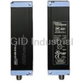
Light Grid Sensor AS1-HD-HR-010-J
Reflector Sensor 4-Pin CS-A1-02-G-05
Request a Quote

The quote request has been received
Close

Facing challenges or have inquiries? Feel free to contact us!
Call Us +1-469-283-2440
What they say about us
FANTASTIC RESOURCE
One of our top priorities is maintaining our business with precision, and we are constantly looking for affiliates that can help us achieve our goal. With the aid of GID Industrial, our obsolete product management has never been more efficient. They have been a great resource to our company, and have quickly become a go-to supplier on our list!
Bucher Emhart Glass
EXCELLENT SERVICE
With our strict fundamentals and high expectations, we were surprised when we came across GID Industrial and their competitive pricing. When we approached them with our issue, they were incredibly confident in being able to provide us with a seamless solution at the best price for us. GID Industrial quickly understood our needs and provided us with excellent service, as well as fully tested product to ensure what we received would be the right fit for our company.
Fuji
HARD TO FIND A BETTER PROVIDER
Our company provides services to aid in the manufacture of technological products, such as semiconductors and flat panel displays, and often searching for distributors of obsolete product we require can waste time and money. Finding GID Industrial proved to be a great asset to our company, with cost effective solutions and superior knowledge on all of their materials, it’d be hard to find a better provider of obsolete or hard to find products.
Applied Materials
CONSISTENTLY DELIVERS QUALITY SOLUTIONS
Over the years, the equipment used in our company becomes discontinued, but they’re still of great use to us and our customers. Once these products are no longer available through the manufacturer, finding a reliable, quick supplier is a necessity, and luckily for us, GID Industrial has provided the most trustworthy, quality solutions to our obsolete component needs.
Nidec Vamco
TERRIFIC RESOURCE
This company has been a terrific help to us (I work for Trican Well Service) in sourcing the Micron Ram Memory we needed for our Siemens computers. Great service! And great pricing! I know when the product is shipping and when it will arrive, all the way through the ordering process.
Trican Well Service
GO TO SOURCE
When I can't find an obsolete part, I first call GID and they'll come up with my parts every time. Great customer service and follow up as well. Scott emails me from time to time to touch base and see if we're having trouble finding something.....which is often with our 25 yr old equipment.
ConAgra Foods