

 Manufacturers
IDEC CORPORATION SA6A-LL4S

Description
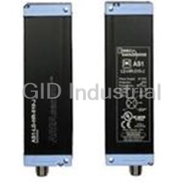
Ultrasonic Analog Distance Detection sensor
SA6A-LL4S
Part Number
SA6A-LL4S
Price
Request Quote
Manufacturer
IDEC CORPORATION
Lead Time
Request Quote
Category
Sensors and Transducers » Specialized Sensor
Specifications
Manufacturer
IDEC Corporation
Manufacturers Part #
SA6A-LL4S
Sub-Category
Specialized Sensors
Factory Pack Quantity
1
Datasheet

Extracted Text
SA6A: Ultrasonic Analog Distance Detection Sensors Sensors SA6A: Ultrasonic Analog Distance Detection Sensors Key features of the SA6A include: • Noise protection is available in two modes of operation • Fuzzy logic eliminates the adverse effects of temperature ţuctuation and air turbulence • Hold mode is ideal for sensing liquid levels without the chatter often caused by surface ripples • Three sensing ranges optimize resolution: Short range: 1.97" to 11.81" (± 0.04") Medium range:3.94" to 39.37" (± 0.08") Long range:7.87" to 78.74" (± 0.19") • Shape, size, color, and material do not impair high-precision measurement • Select analog output (4 to 20mA) for continuous values; use digital output (on/off); or use both • An eight-dot LED meter provides a dynamic display of detected positions Power Voltage 12 to 24V DC (ripple 10% maximum) Current Draw 100mA (maximum) Dielectric Strength Between live and dead parts: 1000V, 50/60Hz, 1 minute Insulation Resistance Between live and dead parts: 100MΩ (minimum) with 500V DC megger –10° to +60°C Operating Temperature (performance will be adversely affected if the sensor becomes coated with ice) Storage Temperature –30°C to +70°C Operating Humidity 35 to 70% RH (avoid condensation) Damage limits: 10 to 55Hz, amplitude 1.5mm p-p, 2 hours in each of 3 axes Vibration Resistance (when de-energized) 2 Shock Resistance Damage limits: 500m/sec (approximately 50G) 3 shocks in each of 3 axes Noise Resistance Power line: 500V; Pulse width: 1µsec, 50/60Hz (using a noise simulator) Material Housing: diecast zinc; Coverplate: polyarylate IP65 — IEC Pub 529: Sensors rated IP65 are dust-tight, water-resistant, and perform Degree of Protection best when not subjected to heavy particle or water blasts 2 Cable Cable type: 6-core cabtyre cable 0.2mm , 6'–6-3/4" (2m) long Weight Short and medium range: 260g; Long range: 270g Short and medium range: 1.96"H x 0.82"W x 3.19"D (50mm H x 21mm W x 81mm D) Dimensions Long range: 3.19"H x 1.14"W x 3.33"D (50mm H x 29mm W x 84.5mm D) Q Q-24 www.idec.com USA: (800) 262-IDEC or (408) 747-0550, Canada: (888) 317-IDEC Sensors General Specifications Sensors Sensors SA6A: Ultrasonic Analog Distance Detection Sensors Part Numbers: Short Sensing Range Part Number Output Sensing Range (A Mode) Sensing Range (B Mode) Linearity/Resolution SA6A-L1K4S NPN 3.94" to 11.81" ± 0.4" 1.97" to 11.81" ± 0.4" ± 0.04" (1mm) PNP (100mm to 300mm ± 10mm) (50mm to 300mm ± 10mm) SA6A-L1L4S Part Numbers: Medium Sensing Range Part Number Output Sensing Range (A Mode) Sensing Range (B Mode) Linearity/Resolution SA6A-LK4S NPN 7.87" to 39.37" ± 0.8" 3.94" to 39.37" ± 0.8" ± 0.08" (2mm) PNP (200mm to 1m ± 20mm) (100mm to 1m ± 20mm) SA6A-LL4S Part Numbers: Long Sensing Range Part Number Output Sensing Range (A Mode) Sensing Range (B Mode) Linearity/Resolution SA6A-L2K4S NPN 15.75" to 78.74" ± 1.6" 7.87” to 78.74" ± 1.6" ± 0.19" (5mm) PNP (400mm to 2m ± 40mm) (200mm to 2m ± 40mm) SA6A-L2L4S SA6A-L1K4S, -L1L4S SA6A-LK4S, -LL4S SA6A-L2K4S, -L2L4S 4 to 20mA (Ţxed range) 4 to 20mA (Ţxed range) 4 to 20mA (Ţxed range) Analog Output ± 0.08mA ± 0.04mA ± 0.05mA Error DeŢned as how accurate the actual analog output is, with respect to distance ± 0.04" (1mm) ± 0.08" (2mm) ± 0.19" (5mm) Resolution DeŢned as the smallest object or the shortest distance that can be detected with reliability NPN or PNP transistor open collector, 100mA, 30V DC (maximum); Residual: 1.5V (NPN), 2.5V (PNP) Digital Output NPN or PNP transistor open collector, 100mA, 30V DC (maximum); Residual: 1.5V (NPN), 2.5V (PNP) Alarm Output A or B mode: Level Meter Represents analog output level on an 8-dot LED display, corresponding to object distance On: When digital output is on (red LED) Out LED On: When power is on (red LED) Power LED On: When environment change occurs (red LED) Alarm LED On: When stable operation is ensured (green LED) Stable LED Analog: 12Hz Analog: 8Hz Analog: 5Hz Response: Digital (A mode): 22Hz Digital (A mode): 15Hz Digital (A mode): 10Hz Normal Mode Digital (B mode): 15Hz Digital (B mode): 10Hz Digital (B mode): 7Hz Analog/Digital: 4Hz Analog/Digital: 3Hz Analog/Digital: 2Hz Response: Fuzzy Mode Analog/Digital: 4Hz Analog/Digital: 3Hz Analog/Digital: 2Hz Response: Hold Mode Analog: 48ms Analog: 70ms Analog: 90ms Response Time Digital (A mode): 16ms Digital (A mode): 24ms Digital (A mode): 30ms Digital (B mode): 24ms Digital (B mode): 36ms Digital (B mode): 45ms Internal Two sensors synchronized, alternate oscillations prevent interference; response time is doubled Synchronous Mode Three or more sensors synchronized with timing pulse signal: External On/Off (A mode) ≥ 15ms On/Off (A mode) ≥ 20ms On/Off (A mode) ≥ 30ms Synchronous Mode Q On/Off (B mode) ≥ 20ms On/Off (B mode) ≥ 30ms On/Off (B mode) ≥ 45ms Approximately 290kHz Approximately 200kHz Approximately 130kHz Oscillation Frequency ± 10° (half wave: -6 dB) ± 7° (half wave: -6 dB) ± 7° (half wave: -6 dB) Directivity Temperature ± 0.06% per °C (± 12 µA per °C) Characteristics 0.24" (6mm) 0.39" (10mm) 0.79" (20mm) Hysteresis DeŢned as the difference between the operating point and the release point www.idec.com USA: (800) 262-IDEC or (408) 747-0550, Canada: (888) 317-IDEC Q-25 Function SpeciŢcations SA6A: Ultrasonic Analog Distance Detection Sensors Sensors Dimensions Short and Medium Range 0.51"(13mm) Long Range Short Range and Long Range Medium Range 0.65" (16.5mm) 0.12" Ø 0.157" 0.12" 0.87" (3mm) 0.77" (3mm) (M4) (22mm) 2.68"(68mm) (19.5mm) Tapped Two Places 0.55" 1.57" (14mm) (40mm) All Three Styles 0.87" 6'– 6-3/4" (22mm) 1.97" x Ø 0.21" 1.30" (50mm) (33mm) (2m x Ø 5.4mm) 1.30" (33mm) 1.14" (29mm) 2.44" (62mm) 0.24” All Three Styles (6mm) 0.12" 0.83" (21mm) (3mm) Short and Medium Range 3.19" (81mm) Long Range 3.33" (84.5mm) Q Q-26 www.idec.com USA: (800) 262-IDEC or (408) 747-0550, Canada: (888) 317-IDEC Sensors Sensors Sensors General Information General Information Extraneous Light SpeciŢcations Bright, extraneous light such as sunlight, incandescent lights, or ţuorescent Do not operate a sensor under any conditions exceeding these speciŢcations. lights may impair the performance of sensors in detecting color or light. Do not operate a sensor under current and voltage conditions other than 3. SA6A ultrasonic sensors are not affected by extraneous light. those for which the individual sensor is rated. Do not exceed the recommended operating temperature and humidity. Although sensors are rated for operation below 0°C, this speciŢcation does Make sure that extraneous light does not exceed recommended levels found not imply that performance characteristics will remain constant under pro- in the individual speciŢcations sections. When 500 lux is speciŢed, this is longed freezing conditions. Continued exposure and the accompanying frost, equal to 50 footcandles. The average factory illumination is ordinarily below ice, dew, and condensation which accumulate on the optical surface will this level, except in areas where visual inspection is being performed. Only in adversely affect sensor performance. such brightly lit areas is incident light of particular concern. To maintain superior performance characteristics, do not exceed vibration and Unwanted light interference can often be avoided simply by making sure that shock resistance ratings while operating a sensor. In addition, avoid isolated the optical receiver is not aimed directly toward a strong light source. When impacts to the sensor housing which are severe enough to adversely affect mounting direction cannot be adjusted, place a light barrier between all the waterproof characteristics. nearby light sources and the receiver. Reţected-Light Sensors When installing sensors which detect reţected light, make sure that IEC (International Electrotechnical Commission) Ratings unwanted light reţections from nearby surfaces, such as the ţoor, walls, reţective machinery, or stainless steel, do not reach the optical receiver. Sensors rated IP67 are resistant to moisture when occasionally immersed in Also, make sure that reţected-light sensors mounted in close proximity do not still water. Sensors rated IP64 through IP66 are resistant to moisture when cause interfering reţections. When it is not possible to maintain the recom- occasionally subjected to splashing or when located in the vicinity of turbu- mended clearance between sensors, as noted in the individual installation lent waters. These ratings do not imply that a sensor is intended for use sections, provide light barriers between sensors. under continual high-pressure water spray. Avoid such applications to main- tain optimal sensor performance. Through-Beam Sensors Sensors rated IP64 through IP67 are dust-tight and water-tight. For best per- formance, avoid using any sensor in an area where it will be subjected to A slit attachment is available to modify the beam size of through-beam sen- heavy particle blasts and where dust, water, or steam will accumulate on the sors. This option is recommended for detecting very small objects (near the optical surface. size of the smallest object which a sensor can detect) or for eliminating light interference when sensors are mounted in close proximity. Laser Sensors Start-up IMPORTANT: Always consider safety when installing a laser sensor of any kind. Make sure that the laser beam cannot inadvertently shine into the eyes of people passing by or working in the vicinity. See safety information on page Q-20. Do not test the housing for dielectric strength and insulation resistance, since the housing is connected to the electronic circuit ground of a sensor. Do not perform dielectric strength and insulation resistance tests on electrical sys- tems without disconnecting photoelectric sensors, as such testing may result Mounting in damage to the sensor. The mounting bracket and hardware are included with sensors, where appli- Several lines of sensors, as noted in the individual operation sections, are cable. Use the appropriate hardware for mounting, along with washers and provided with an internal circuit to turn an output off for a speciŢed amount of spring washers or lock nuts. Do not overtighten attachment hardware. Over- time upon power-up. This delay is normal; it prevents a transient state when tightening causes damage to the housing and will adversely affect the water- turning power on. proof characteristics of the sensor. Best results can be obtained when the sensor is mounted so that the object sensed is in the center of the beam, rather than when the object is located Optimum Performance near the edges of the sensing window. In addition, the most reliable sensing occurs when the majority of the objects being sensed are well within the sensing range, rather than at the extreme near and far limits. The optical surface of each sensor must be cleaned on a regular basis for con- tinual superior performance. Use a soft cloth dipped in isopropyl alcohol to remove dust and moisture build-up. IMPORTANT: Do not use organic solvents (such as thinner, ammonia, caustic soda, or benzene) to clean any part of a sensor. Q All sensors experience signal inconsistencies under the inţuence of inductive noise. Do not use sensors in close proximity to transformers, large inductive motors, or generators. Avoid using sensors in direct contact with sources of excessive heat. Also avoid operation in close proximity to welding equipment. 1. Even though the SA6A ultrasonic sensor features protection against noise, there may be adverse effects from strong noise. 2. It is strongly recommended to avoid using any sensor where it will be continually subjected to elements which impair perfor- mance or cause corrosive damage to the sensor. In particular, avoid strong vibrations and shocks, corrosive gases, oils, and chemi- cals, as well as blasts of water, steam, dust, or other particles. www.idec.com USA: (800) 262-IDEC or (408) 747-0550, Canada: (888) 317-IDEC Q-55 General Information Sensors Wiring Glossary Attenuation: Reduction of beam intensity as a result of environmental fac- Avoid running high-voltages or power lines in the same conduit with sensor tors such as dust, humidity, steam, etc. signal lines. This prevents inaccurate results or damage from induced noise. Use a separate conduit when the inţuence of power lines or electromagnetic Dark on: Output energized when light is not detected by the receiving ele- equipment may occur, particularly when the distance of the wiring is extended. ment. For through-beam sensors, light from the projector is not detected by the receiver when an object is present. For reţected light sensors, light is IMPORTANT: Connect the sensor cables and wires as noted in the individual not detected when it is not reţected from an object surface. Wiring sections. Failure to connect as shown in wiring diagrams will result in damage to the internal circuit. Diffuse-reţected light sensors: Sensors that detect all scattered, reţected light. Light reţected from nearby surfaces, as well as intended When extending sensor cables and wires, make sure to use cables equal or object surface, is detected. Diffuse-reţected light sensors are often called superior to that recommended in the individual speciŢcations sections. “proximity switches,” since they switch when any object is near. Also use to detect color contrast when colors reţect light intensity differently (green When wiring terminals, be sure to prevent contact between adjoining termi- LED recommended for this application). nals. When using ring or fork lug terminals, use the insulated sleeve style only. Each sensor terminal can accept only one ring of fork lug terminal. EEPROM: Acronym which stands for electronically erasable, programma- ble, read only memory. On ISF series photoelectric sensors, use recommended cable, along with the attached packing gland and washer, when wiring the terminals. This ensures Excess gain: Ratio of optical power available at a given projector-to- waterproof and dustproof characteristics. receiver range divided by the minimum optical power required to trigger the receiver. Power Supply Extraneous light: Incident light received by a sensor, irrelated to the pres- ence or absence of object being detected. Extraneous light is usually Noise resistance characteristics are improved when a sensor is grounded to unwanted background light such as sunlight and incandescent lamps in the 0V power terminal. If the 0V power terminal is not at ground potential, use close proximity. a ceramic 0.01µF capacitor which can withstand 250V AC minimum. ΔE: The measurement of color difference as a three-variable function, When using a switching power supply, be sure to ground the FG terminal to located on an XYZ axis of light, hue, and chroma values. eliminate high-frequency noise. The power supply should include an insulat- ing transformer, not an autotransformer. Hysteresis: Operating point and release point at different levels. For solid state sensors, this is accomplished electrically. For mechanical switches, it On ISF series photoelectric sensors, the power supply should be sized accord- results from storing potential energy before the transition occurs. ing to the voltage drop through the lead wire when using a long extension for the DC type (328' or 100m maximum extension). Light on: Output energized when light is detected by receiving element. For through-beam sensors, light from the projector is detected by the Power Supply receiver when an object is not present. For reţected light sensors, light is detected when it is reţected from an object surface. The compact PS5R-A power supply is the perfect companion item for most Linearity: Measurement of how nearly linear, that is, how accurate actual IDEC sensors. This power supply is only 1.77" (45mm) wide, 3.15" (80mm) tall, analog output is, with respect to distance. and 2.76" (70mm) deep. Call an IDEC representative for more details. NPN/PNP: Types of open collector transistors. NPN is a sink transistor; Part Number Output Ratings output on establishes negative potential difference. PNP is a source tran- sistor; output on establishes positive potential difference. PS5R-A12 12V DC, 0.62A Polarizing: Filtering out all reţected light except that which is projected in PS5R-A24 24V DC, 0.32A one plane only. Polarized retro-reţected light sensors detect the light from corner-cube type reţectors when an object is not present. Reţected-light sensors: Sensors with the projector and receiver in one housing. Light is projected by the light source, and reţected light is received by the optical surface. Includes diffuse-reţected, retro-reţected, limited-reţected, and spot-reţected sensors. Repeatability: Ability of a sensor to reproduce output readings consis- Miscellaneous tently when the same value is applied consecutively, in the same direction, for a speciŢed number of cycles, or for a speciŢed time duration. Strong magnetic Ţelds may detract from the accuracy of the sensing measure- Resolution: Overall dimension of the smallest object which can be ment. Avoid mounting a sensor directly to machinery, since the housing is con- detected (when sensing the presence of an object) or smallest increment of nected to the electronic circuit ground of the sensor. If it is necessary to mount distance which can be distinguished with reliable results (when sensing a sensor on machinery, use the insulating plate and sleeve provided. the position of an object). Response time: Time elapsed between input and output. Total response time is the sum of object detection, ampliŢer response, and output response times. Retro-reţective scan: This type of reţected light sensor uses a special reţector to return projected light when an object is not present. Sensor Q detects the presence of an object when the light is reţected differently. Through-beam sensors: Sensors with a separate projector and receiver. The light source from the projector is detected by the receiver, except when an object is present. Transient: Undesirable surge of current (many times larger than normal current) for a very short period, such as during the start-up of an inductive motor. Q-56 www.idec.com USA: (800) 262-IDEC or (408) 747-0550, Canada: (888) 317-IDEC Sensors
Frequently asked questions
How does Electronics Finder differ from its competitors?

Is there a warranty for the SA6A-LL4S?
Which carrier will Electronics Finder use to ship my parts?
Can I buy parts from Electronics Finder if I am outside the USA?
Which payment methods does Electronics Finder accept?
Why buy from GID?

Quality
We are industry veterans who take pride in our work

Protection
Avoid the dangers of risky trading in the gray market

Access
Our network of suppliers is ready and at your disposal

Savings
Maintain legacy systems to prevent costly downtime

Speed
Time is of the essence, and we are respectful of yours
Related Products
Digital Contrast Sensor With Metal Housing 95ACC1030
Digital Contrast Sensor With Metal Housing 95ACC2260
Digital Contrast Sensor With Metal Housing 95ACC2540
Digital Contrast Sensor With Metal Housing 95ACC5340
Light Grid Sensor AS1-HD-HR-010-J
Reflector Sensor 4-Pin CS-A1-02-G-05
Request a Quote

The quote request has been received
Close

Facing challenges or have inquiries? Feel free to contact us!
Call Us +1-469-283-2440
What they say about us
FANTASTIC RESOURCE
One of our top priorities is maintaining our business with precision, and we are constantly looking for affiliates that can help us achieve our goal. With the aid of GID Industrial, our obsolete product management has never been more efficient. They have been a great resource to our company, and have quickly become a go-to supplier on our list!
Bucher Emhart Glass
EXCELLENT SERVICE
With our strict fundamentals and high expectations, we were surprised when we came across GID Industrial and their competitive pricing. When we approached them with our issue, they were incredibly confident in being able to provide us with a seamless solution at the best price for us. GID Industrial quickly understood our needs and provided us with excellent service, as well as fully tested product to ensure what we received would be the right fit for our company.
Fuji
HARD TO FIND A BETTER PROVIDER
Our company provides services to aid in the manufacture of technological products, such as semiconductors and flat panel displays, and often searching for distributors of obsolete product we require can waste time and money. Finding GID Industrial proved to be a great asset to our company, with cost effective solutions and superior knowledge on all of their materials, it’d be hard to find a better provider of obsolete or hard to find products.
Applied Materials
CONSISTENTLY DELIVERS QUALITY SOLUTIONS
Over the years, the equipment used in our company becomes discontinued, but they’re still of great use to us and our customers. Once these products are no longer available through the manufacturer, finding a reliable, quick supplier is a necessity, and luckily for us, GID Industrial has provided the most trustworthy, quality solutions to our obsolete component needs.
Nidec Vamco
TERRIFIC RESOURCE
This company has been a terrific help to us (I work for Trican Well Service) in sourcing the Micron Ram Memory we needed for our Siemens computers. Great service! And great pricing! I know when the product is shipping and when it will arrive, all the way through the ordering process.
Trican Well Service
GO TO SOURCE
When I can't find an obsolete part, I first call GID and they'll come up with my parts every time. Great customer service and follow up as well. Scott emails me from time to time to touch base and see if we're having trouble finding something.....which is often with our 25 yr old equipment.
ConAgra Foods