

 Manufacturers
IDEC CORPORATION TLU-015
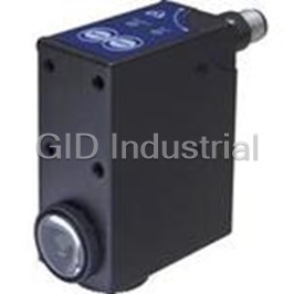
Description
Contrast Sensor
TLU-015
Part Number
TLU-015
Price
Request Quote
Manufacturer
IDEC CORPORATION
Lead Time
Request Quote
Category
Sensors and Transducers » Specialized Sensor
Specifications
Manufacturer
IDEC Corporation
Manufacturers Part #
TLU-015
Sub-Category
Specialized Sensors
Factory Pack Quantity
1
Datasheet

Extracted Text
DIMENSIONS FUNCTION SELECTION When FORMAT is 81.2 N°. FORMAT 1 2 3 4 TLμ-x6x selected (configuration input REMOTE A 0V 0V +V +V n°.4 M5x6 selector section 1), the 7.5 4.3 n°.4 M5x0.24 input REMOTE B 0V +V 0V +V MARK and BKGD M12 CONNECTOR puskbuttons are enabled and connecting the REMOTE inputs (TLμ-xx1) 15 to the power supply as shown in the table allows to select up to 4 different settings (formats). This is the factory setting. If a non-set format is selected, the sensor is disabled and the green LED flashes at a low rate. A setting can be stored selecting a format and executing the procedure TLμ SERIES 18 mm LENS 9 mm LENS described in the “SETTING” paragraph. 14.1 27.5 28 20.9 When SET is selected (configuration selector section 1), the MARK and INSTRUCTION MANUAL n°.4 M5x6 BKGD pushbuttons are disabled; the REMOTE inputs (TLμ-x1x) replace 36.6 28 n°.4 M5x0.24 the pushbuttons functionality. Connecting the REMOTE A and B inputs to the positive power supply rail is equivalent to pressing the MARK and BKGD pushbuttons respectively. Connect the unused inputs to 0V. CONTROLS . TIMING FUNCTION READY LED OUTPUT LED ON OUTPUT LED When ON is selected ON MARK BKGD The red LED indicates the output status. PUSHBUTTON PUSHBUTTON (configuration selector OUT without TIMER OFF OFF mm section 2), a delay timer ON ON READY LED function is enabled which 20 ms 20 ms OUT with TIMER OFF During functioning, the green LED permanently ON indicates a normal OFF extends the minimum ON operating condition; fast blinking indicates an output overload condition. CAP output time to 20 ms. The factory setting is OFF (timer disabled). See the “SETTING” paragraph for setup procedure indications. MARK / BKGD PUSHBUTTON SETTING The pushbutton activates the setup procedure. TECHNICAL DATA A two-step setup procedure adjusts the switching threshold and the Power supply: 10 … 30 Vdc limit values; reverse polarity protection LIGHT/DARK mode. Using the procedure given below the sensor output INSTALLATION is set to be ON when a mark is detected. Ripple: 2 Vpp max. Operating distance is rated 1) Output ON state acquisition (MARK) Current consumption 80 mA max. starting from the lens front face. (output current excluded): Place the target mark into the emission spot and press the MARK The M12 connector or cable exit pushbutton until the green LED turns OFF. Output: NPN or PNP, pull down/up resistance 10 kΩ (short-circuit protection) can be rotated in three positions Don’t move the mark during the setting phase (about 1 sec). Output current: 200 mA max. by loosening the locking screw. 2) Output OFF state acquisition (BKGD) Analog output: 0 … 2 V ± 10% (white 90%); 5.5 V max.; ripple 40 mVpp max.; output resistance 2.2 kΩ Tighten the locking screw when Place the background into the emission spot and press the BKGD Output saturation voltage: 1V max. NPN versions / 2V max PNP versions finished. pushbutton; the green LED blinks once. Response time: 50 μs max. / 25 μs max. (TLμ-4xx/5xx) The beam direction may be Don’t move the background during the setting phase. changed swapping the cap and Switching frequency: 10 kHz max. / 20 kHz max. (TLμ-4xx/5xx) the lens. Timing function: 20 ms minimum output ON If the green LED lights permanently ON, a safe operation has been Detecting marks on a reflective surface is improved adjusting the beam Indicators: OUTPUT LED (RED) / READY LED (GREEN) obtained; if it flashes at a low rate the setup procedure has failed due to direction to 5° … 20° from surface axis. Setting: by pushbuttons / by wires; 4 settings storage cable version insufficient contrast; repeat the procedure from the beginning. Retention data: non volatile EEPROM memory CONNECTIONS Operating temperature: -10 … 55 °C Storage temperature: -20 … 70 °C BROWN Electric shock protection: Class 1 10 … 30 Vdc + Operating distance: 9 mm (TLμ-x1x/4xx/5xx) / 18 mm (TLμ-x6x) RED Minimum spot dimension: 1.5 x 5 mm (TLμ-x1x) / 2 x 7 mm (TLμ-x6x) / ∅ 3 mm (TLμ-4xx/5xx) REMOTE A * Depth of field: ± 3 mm (TLμ-x1x/4xx/5xx) / ± 4 mm (TLμ-x6x) ORANGE REMOTE B Emission type: green (526 nm) / red (630 nm) with automatic selection or white (400-700 nm) * DECLARATION OF CONFORMITY Ambient light rejection: according to EN 60947-5-2 GREY We DATASENSOR S.p.A. declare under our sole responsibility that ANALOG OUTPUT Vibration: 0.5 mm amplitude, 10 … 55 Hz frequency, in every axis (EN60068-2-6) these products are conform to the 2004/108/CE, 2006/95/CE Directives WHITE Shock resistance: 11 ms (30 G) 6 shock in every axis (EN60068-2-27) NPN/PNP and successive amendments. DARK/LIGHT selection: teach-in procedure BLUE Housing: ZAMA 0 V WARRANTY Protection class: IP67 DATASENSOR S.p.A. warrants its products to be free from defects. Connections: 3 m shielded cable ∅ 6.1 mm / M12 4-pole connector DATASENSOR S.p.A. will repair or replace, free of charge, any product SHIELD ** Weight: 450 g. max. cable versions / 310 g. max. connector versions found to be defective during the warranty period of 36 months from the * = Connect the unused REMOTE wires to 0 V. manufacturing date. ** = The cable shield is insulated from the sensor housing; it is recommended This warranty does not cover damage or liability deriving from the to connect the shield to 0 V. CONFIGURATION DETECTION DIAGRAM improper application of DATASENSOR products. REMOTE A double selector and a switch are ON TIMING Relative sensitivity DATASENSOR S.p.A. Via Lavino 265 % available removing the sensor side SET ON TL -x1x/4xx/5xx μ 40050 Monte S. Pietro - Bologna - Italy M12 CONNECTOR 100 cover. The selector allows to enable the Tel: +39 051 6765611 Fax: +39 051 6759324 output timing function and choose the FORMAT OFF 80 http://www.datasensor.com e-mail: info@datasensor.com ANALOG OUTPUT 1 2 10 … 30 Vdc pushbuttons and REMOTE inputs TL -x6x μ + 60 2 1 (WHITE) (BROWN) operating mode; the switch allows to select the output type (NPN or DATASENSOR S.p.A. cares for the environment: 100% recycled 40 PNP). paper. 20 3 4 0 V NPN/PNP DATASENSOR S.p.A. reserves the right to make modifications - 0 (BLACK) (BLUE) and improvements without prior notification. 0 2 4 6 8 10 12 14 16 18 20 22 24 26 28 30 mm Operating distance 826000024 Rev.F Ø25 58 31 4.3 42.2 Ø25 24 39.8 Ø6.1 M12x1 DIMENSIONS FUNCTION SELECTION The Auto-Set function automatically adapts the switching threshold according to the mark and background sequence that has to be 81.2 detected. The sensor automatically places the switching threshold at a lower level mm n°.4 M5x6 respect to the signal corresponding to the light reflected from the mark. 4.3 n°.4 M5x0.24 The difference between the signal corresponding to the mark and the switching threshold represent the hysterisis. The light/dark operating mode selection for the detection of a mark lighter than its background or viceversa, can be obtained connecting the 15 pin n° 2 of the M12 connector: free or connected to 0Vdc for dark mode, TLµ Auto-Set SERIES connected to +Vcc for light mode. The analogue output is not available in the models with automatic Auto- INSTRUCTION MANUAL Set setting. A model with PNP output and a model with NPN output are available; the selection of the output type cannot be made, in both cases, using the selectors present on the sensor. 9mm LENS 14.1 27.5 28 CONTROLS DETECTION DIAGRAM n°.4 M5x6 OUTPUT LED 36.6 28 n°.4 M5x0.24 Relative sensitivity The yellow LED indicates the output status. % POWER ON LED 100 The green LED indicates that the sensor is operating. 80 60 INSTALLATION 40 . OUTPUT LED Operating distance is rated 20 starting from the lens front 0 face. mm . The M12 connector can be POWER ON LED 0 2 4 6 8 10 12 14 16 18 20 22 rotated in three positions by Operating distance loosening the locking screw. Tighten the locking screw when finished. The beam direction may be changed swapping the cap and the lens. CAP WARNING: To detect marks on a reflective surface and/or in presence of very light colours it’s needed to adjust the beam direction to 5°…20° from surface axis. TECHNICAL DATA 5...20° 5...20° Power supply: 10 … 30 Vdc limit values; reverse polarity protection Ripple: 2 Vpp max. Current consumption � 50 mA max. (output current excluded): Output: NPN (TLµ-4xx) o (TLµ-5xx) PNP, pull down/up resistance 22 kΩ (short-circuit protection) Output current: 200 mA max. Output saturation voltage: 1V max. NPN versions / 2V max PNP versions DECLARATION OF CONFORMITY Response time: 25 µs max. We DATASENSOR S.p.A. declare under our sole responsibility that Switching frequency: 20 kHz max. these products are conform to the 2004/108 CEE, 73/23 CEE Directives Indicators: OUTPUT LED (YELLOW) / POWER ON LED (GREEN) and successive amendments. Setting: dynamic automatic CONNECTIONS Operating temperature: -10 … 55 °C WARRANTY Storage temperature: -20 … 70 °C DATASENSOR S.p.A. warrants its products to be free from defects. M12 CONNECTOR Electric shock protection: Class 1 DATASENSOR S.p.A. will repair or replace, free of charge, any product found to be defective during the warranty period of 36 months from the Operating distance: 9 mm manufacturing date. Minimum spot dimension: ∅ 3 mm DARK/LIGHT 10 … 30 Vdc This warranty does not cover damage or liability deriving from the + Depth of field: ± 3 mm 2 1 (WHITE) (BROWN) improper application of DATASENSOR products. Emission type: LED with white light (400-700 nm) Ambient light rejection: according to EN 60947-5-2 DATASENSOR S.p.A. Via Lavino 265 3 Vibration: 0.5 mm amplitude, 10 … 55 Hz frequency, for every axis (EN60068-2-6) 4 40050 Monte S. Pietro - Bologna - Italy OUTPUT 0 V Shock resistance: 11 ms (30 G) 6 shock for every axis (EN60068-2-27) - Tel: +39 051 6765611 Fax: +39 051 6759324 (BLACK) (BLUE) DARK/LIGHT selection: by wire http://www.datasensor.com e-mail: info@datasensor.com Housing: Zama DATASENSOR S.p.A. cares for the environment: 100% recycled Protection class: IP67 paper. Pin 2 free or connect to 0V: DARK mode Connections: M12 4-pole connector DATASENSOR S.p.A. reserves the right to make modifications Pin 2 connect to 10…30Vdc: LIGHT mode Weight: 310 g. max. connector versions and improvements without prior notification. 826000843 Rev.C 58 31 4.3 42.2 Ø25 24 39.8 M12x1
Frequently asked questions
How does Electronics Finder differ from its competitors?

Is there a warranty for the TLU-015?
Which carrier will Electronics Finder use to ship my parts?
Can I buy parts from Electronics Finder if I am outside the USA?
Which payment methods does Electronics Finder accept?
Why buy from GID?

Quality
We are industry veterans who take pride in our work

Protection
Avoid the dangers of risky trading in the gray market

Access
Our network of suppliers is ready and at your disposal

Savings
Maintain legacy systems to prevent costly downtime

Speed
Time is of the essence, and we are respectful of yours
Related Products
Digital Contrast Sensor With Metal Housing 95ACC1030
Digital Contrast Sensor With Metal Housing 95ACC2260
Digital Contrast Sensor With Metal Housing 95ACC2540
Digital Contrast Sensor With Metal Housing 95ACC5340
Light Grid Sensor AS1-HD-HR-010-J
Reflector Sensor 4-Pin CS-A1-02-G-05
Request a Quote

The quote request has been received
Close

Facing challenges or have inquiries? Feel free to contact us!
Call Us +1-469-283-2440
What they say about us
FANTASTIC RESOURCE
One of our top priorities is maintaining our business with precision, and we are constantly looking for affiliates that can help us achieve our goal. With the aid of GID Industrial, our obsolete product management has never been more efficient. They have been a great resource to our company, and have quickly become a go-to supplier on our list!
Bucher Emhart Glass
EXCELLENT SERVICE
With our strict fundamentals and high expectations, we were surprised when we came across GID Industrial and their competitive pricing. When we approached them with our issue, they were incredibly confident in being able to provide us with a seamless solution at the best price for us. GID Industrial quickly understood our needs and provided us with excellent service, as well as fully tested product to ensure what we received would be the right fit for our company.
Fuji
HARD TO FIND A BETTER PROVIDER
Our company provides services to aid in the manufacture of technological products, such as semiconductors and flat panel displays, and often searching for distributors of obsolete product we require can waste time and money. Finding GID Industrial proved to be a great asset to our company, with cost effective solutions and superior knowledge on all of their materials, it’d be hard to find a better provider of obsolete or hard to find products.
Applied Materials
CONSISTENTLY DELIVERS QUALITY SOLUTIONS
Over the years, the equipment used in our company becomes discontinued, but they’re still of great use to us and our customers. Once these products are no longer available through the manufacturer, finding a reliable, quick supplier is a necessity, and luckily for us, GID Industrial has provided the most trustworthy, quality solutions to our obsolete component needs.
Nidec Vamco
TERRIFIC RESOURCE
This company has been a terrific help to us (I work for Trican Well Service) in sourcing the Micron Ram Memory we needed for our Siemens computers. Great service! And great pricing! I know when the product is shipping and when it will arrive, all the way through the ordering process.
Trican Well Service
GO TO SOURCE
When I can't find an obsolete part, I first call GID and they'll come up with my parts every time. Great customer service and follow up as well. Scott emails me from time to time to touch base and see if we're having trouble finding something.....which is often with our 25 yr old equipment.
ConAgra Foods