

 Manufacturers
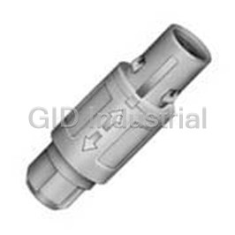
LEMO EGG.2T.302.KLL

Description
None available.
Part Number
EGG.2T.302.KLL
Price
Request Quote
Manufacturer
LEMO
Lead Time
Request Quote
Category
Connectors » Connector Circular
Specifications
Manufacturer
LEMO
Manufacturers Part #
EGG.2T.302.KLL
Sub-Category
Circular Connectors
Series
T
Factory Pack Quantity
1
Datasheet

Extracted Text
T SERIES IP 68 PUSH-PULL CONNECTORS ® ® T series T series connectors have been specifically designed for outdoor applications. They include an inner sleeve and seals to pre- vent penetration of solids or liquids.This series is watertight when mated to give a protection index of IP68 as per IEC 60529 standard and have the following main features: - IP68 mated - Compatible with existing B sockets - Push-Pull self-latching system - Same mounting hole as B sockets - Mechanical key (FGG) with multiple keys - Black-chrome plated brass and plastic outershell available to avoid cross-mating - Multipole types 2 to 32 contacts - High packing density for space savings - For cables 1.0 up to 10.5 mm - 360° shielding for full EMC shielding - Solder, crimp or print contacts Technical Characteristics Mechanical and Climatical Value Standard Endurance > 3000 cycles IEC 60512-5 test 9a Humidity up to 95% at 60°C – 1) Temperature range -55°C, +200°C / (-20°C, +80°C) – Resistance to vibration 10-2000 Hz, 15 g IEC 60512-4 test 6d Shock resistance 100 g, 6 ms IEC 60512-4 test 6c Salt spray corrosion test > 1000 h IEC 60512-6 test 11f 2) Protection index (mated) IP68/IP66 IEC 60529 Latching retention force (average value) From 85 N up to 300 N (depending of the size) – Climatical category 50/175/21 IEC 60068-1 Electrical Value Standard Shielding efficiency > 75 dB at 10 MHz / > 40 dB at 1 GHz IEC 60169-1-3 Material and Treatments Outershell and collet nut Latch sleeve/earthing crown Other metallic components Material Surface treatment Material Surface treatment Material Surface treatment Brass Chrome Brass/Bronze Nickel Brass Nickel 3) Brass Black chrome Brass/Bronze Nickel Brass Nickel POM – Brass/Bronze Nickel Brass Nickel Contacts Insulators Material Contact type Material Brass (UNS C 34500) Male contact PEEK Bronze (UNS C 54400) Female contact 1) 2) ® Note: operating temperature is -20°C, +80°C for watertight or vacuumtight models fitted with an FPM (Viton ) o-ring and Epoxy. IP68 achieved providing 3) that the cable is perfectly circular and that assembly process ensures a high integrity seal. Surface not conductive use socket with earthing tag (HMG). Part Section Showing Internal Components Straight plug Fixed socket 1 outer shell 4 2 6 3 7 5 6 1 2 5 4 3 1 6 7 8 9 10 2 latch sleeve 1 outer shell 3 inner shell 2 earthing crown 4 insulator 3 hexagonal nut 5 male contact 4 insulator 6 split insert carrier 5 female contact earthing cone 7 6 o-ring 8 gasket locking washer 7 collet 9 10 collet nut www.lemo.com ® ® Interconnections Chrome-plated housing models (page 2) Straight plugs Fixed sockets Free sockets FGG PHG EGG FFG FGG PHG EEG Plastic housing models (page 5) Watertight or vacuumtight models (page 4) Straight plug Fixed socket Fixed sockets FGG HEG HMG EGG HGG Part Numbering System Plug and free socket F G G.. 1T 3 0 6. C L A C 4 0 Z Variant Cable ø (page 9) Model (page 2) Collet type (page 9) Alignment key (page 5) Contact: Series A = male solder L = female solder Insert configuration (page 6) C = male crimp M = female crimp Housing: C = Chrome plated brass Insulator: PEEK K = Black Chrome plated brass L = for solder contact B = POM (black) Y = for crimp contact FGG.1T.306.CLAC40Z = Straight plug with key (G) and cable collet for bend relief, 1T series, multipole type with 6 contacts, outer shell in chrome-plated brass, PEEK insulator, male solder contacts, C type collet for 4.0 mm diameter cable and nut for fitting a bend relief. Fixed socket E G G.. 1T 3 0 6. C L L Variant Model (page 3) Contact: L = female solder Alignment key (page 5) A = male solder M = female crimp Series C = male crimp N = female print Insert configuration (page 6) D = male print V = female elbow print Housing: C = Chrome plated brass Insulator: PEEK K = Black Chrome plated brass L = for solder or print contact B = POM Y = for crimp contact EGG.1T.306.CLL = fixed socket, nut fixing, with key (G), 1T series, multipole type with 6 contacts, outer shell in chrome-plated brass, PEEK insulator, female solder contacts. DISCLAIMER The information contained within this catalog and the functions offered are intended to provide information about products. All reasonable efforts have been made to ensure the accuracy of the information. However, LEMO cannot be held responsible for any errors. LEMO does not warrant the accuracy and reserves the right to make changes to the catalog and its functions at any time without notice. www.lemo.com 1 ® ® Chrome-plated housing models FGG Straight plug, cable collet Reference Dimensions (mm) Cable ø ~L Model Series A L M S1 S2 min. max. ~M FGG TT 7.0 33.2 25.2 5.5 5 2.4 3.0 FGG 0T 9.5 39.0 29.0 7.5 7 1.0 5.0 S 2 S 1 FGG 1T 12.0 46.0 35.0 11.0 9 1.3 6.5 FGG 2T 15.0 55.0 43.0 14.0 12 1.3 8.5 FGG 3T 18.8 64.0 49.0 16.0 14 2.6 10.5 FGG Straight plug, cable collet and nut for fitting a bend relief Reference Dimensions (mm) Cable ø ~L Model Series A L M S1 S2 min. max. ~M FGG TT 7.0 32.7 24.7 5.5 6 2.4 3.0 FGG 0T 9.5 38.0 28.0 7.5 7 1.0 5.0 S 2 S 1 FGG 1T 12.0 45.0 34.0 11.0 9 1.3 6.5 FGG 2T 15.0 54.0 42.0 14.0 12 1.3 8.5 FGG 3T 18.8 62.0 47.0 16.0 15 2.6 10.5 FFG Straight plug, non latching, cable collet Reference Dimensions (mm) Cable ø ~L Model Series A L M S1 S2 min. max. ~M FFG TT 7.0 33.2 25.2 6 5 2.4 3.0 FFG 0T 9.5 39.0 29.0 8 7 1.0 5.0 S 2 S 1 FFG 1T 12.0 46.0 35.0 10 9 1.3 6.5 FFG 2T 15.0 55.0 43.0 13 12 1.3 8.5 FFG 3T 18.8 64.0 49.0 16 14 2.6 10.5 PHG Free socket, cable collet Reference Dimensions (mm) Cable ø Model Series A L S1 S2 min. max. ~L PHG TT 7.0 32.0 5.5 5 2.4 3.0 PHG 0T 9.5 38.0 7.5 7 1.0 5.0 S 2 S 1 PHG 1T 12.0 43.5 11.0 9 1.3 6.5 PHG 2T 15.0 52.0 14.0 12 1.3 8.5 PHG 3T 18.8 61.5 16.0 14 2.6 10.5 DISCLAIMER The information contained within this catalog and the functions offered are intended to provide information about products. All reasonable efforts have been made to ensure the accuracy of the information. However, LEMO cannot be held responsible for any errors. LEMO does not warrant the accuracy and reserves the right to make changes to the catalog and its functions at any time without notice. 2 www.lemo.com ş A ş A ş A ş A ® ® PHG Free socket, cable collet and nut for fitting a bend relief Reference Dimensions (mm) Cable ø Model Series A L S1 S2 min. max. ~L PHG TT 7.0 31.5 5.5 6 2.4 3.0 PHG 0T 9.5 37.0 7.5 7 1.0 5.0 S 2 S 1 PHG 1T 12.0 42.5 11.0 9 1.3 6.5 PHG 2T 15.0 51.0 14.0 12 1.3 8.5 PHG 3T 18.8 60.0 16.0 15 2.6 10.5 EGG Fixed socket, nut fixing Reference Dimensions (mm) 1) Model Series A B e E L M N S1 S2 L maxi N EGG TT 10.0 10.2 M7x0.5 5.5 16.0 1.2 13.5 6.3 9 S 2 M EGG 0T 12.0 12.5 M9x0.6 6.0 21.0 1.5 19.1 8.2 11 EGG 1T 15.5 16.0 M12x1.0 6.0 23.0 1.8 21.5 10.5 14 EGG 2T 18.5 19.6 M15x1.0 7.5 26.5 1.8 24.6 13.5 17 E maxi S 1 EGG 3T 23.5 25.1 M18x1.0 9.6 30.1 2.5 25.0 16.5 22 1) Note: maximum length with crimp contacts. EEG Fixed socket, nut fixing, back panel mounting Reference Dimensions (mm) 1) Model Series A B e E L N P S1 L maxi N EEG TT 10.0 10.0 M7x0.5 4.5 16.0 13.5 7 6.3 EEG 0T 12.0 12.0 M9x0.6 6.5 21.0 19.1 9 8.2 EEG 1T 15.5 16.0 M12x1.0 6.5 23.0 21.5 10 10.5 E maxi S 1 EEG 2T 18.5 20.0 M15x1.0 7.5 26.5 24.6 11 13.5 P EEG 3T 23.5 24.0 M18x1.0 7.5 30.1 25.0 12 16.5 1) Note: maximum length with crimp contacts. Panel cut-out Reference Panel cut-out Mounting nut torque Model Series B C L Metal shell Plastic shell L mini Ell TT 6.4 7.1 12.5 1.0 0.4 Ell 0T 8.3 9.1 14.5 2.5 0.4 Ell 1T 10.6 12.1 18.5 4.5 0.7 + 0.1 B 0 Ell 2T 13.6 15.1 22.5 6.0 0.8 Ell 3T 16.6 18.1 27.0 9.0 1.0 DISCLAIMER The information contained within this catalog and the functions offered are intended to provide information about products. All reasonable efforts have been made to ensure the accuracy of the information. However, LEMO cannot be held responsible for any errors. LEMO does not warrant the accuracy and reserves the right to make changes to the catalog and its functions at any time without notice. 3 + 0.1 ø C 0 ş B ş A e e ş A ş B ş A ® ® Watertight or vacuumtight models These models are identified by a letter «P» at the end of the reference. Most of these models are also available in a vacuumtight version. Such models are identified by an additional letter «V» at the end of the part number (certificate on request). Epoxy resin is used to seal these models. The temperature range is -20°C / +80°C. Part Number Example HGG.0T.305.CLLP (5 contacts, resin potted) HGG.0T.305.CLLPV (5 contacts, resin potted and vacuumtight tested) HGG Fixed socket, nut fixing, watertight or vacuumtight L maxi Reference Dimensions (mm) N 1) S 2 M Model Series A B e E L M N S1 S2 HGG TT 10.0 10.2 M7x0.5 5.5 18.0 1.2 15.0 6.3 9 HGG 0T 12.0 12.5 M9x0.6 6.5 22.0 1.5 18.5 8.2 11 HGG 1T 15.5 16.0 M12x1.0 6.0 26.0 1.8 21.5 10.5 14 E maxi S 1 HGG 2T 18.5 19.6 M15x1.0 8.0 30.5 1.8 25.0 13.5 17 HEG Fixed socket, nut fixing, watertight or vacuumtight, back panel mounting L maxi Reference Dimensions (mm) N Model Series A B e E L N P S1 HEG TT 10.0 10.0 M7x0.5 4.5 18.0 15.0 7 6.3 HEG 0T 12.0 12.0 M9x0.6 6.5 22.0 18.5 9 8.2 E maxi S 1 HEG 1T 15.5 16.0 M12x1.0 6.5 26.0 21.5 10 10.5 P HEG 2T 18.5 20.0 M15x1.0 7.5 30.5 25.0 11 13.5 HMG Fixed socket with earthing tag, nut fixing, watertight or vacuumtight, back panel mounting L maxi Reference Dimensions (mm) N Model Series A B e E L N P S1 HMG TT 10.0 10.0 M7x0.5 4.5 18.0 15.0 7 6.3 HMG 0T 12.0 12.0 M9x0.6 6.5 22.0 18.5 9 8.2 E maxi S 1 HMG 1T 15.5 16.0 M12x1.0 6.5 26.0 21.5 10 10.5 P HMG 2T 18.5 20.0 M15x1.0 7.5 30.5 25.0 11 13.5 Panel cut-out Reference Panel cut-out Mounting nut torque L mini Model Series B C L Metal shell Plastic shell Hll TT 6.4 7.1 12.5 1.0 0.4 Hll 0T 8.3 9.1 14.5 2.5 0.4 + 0.1 B 0 Hll 1T 10.6 12.1 18.5 4.5 0.7 Hll 2T 13.6 15.1 22.5 6.0 0.8 DISCLAIMER The information contained within this catalog and the functions offered are intended to provide information about products. All reasonable efforts have been made to ensure the accuracy of the information. However, LEMO cannot be held responsible for any errors. LEMO does not warrant the accuracy and reserves the right to make changes to the catalog and its functions at any time without notice. 4 www.lemo.com + 0.1 ø C 0 ş B ş A ş A e e e ş A ş B ş B ® ® Plastic housing models FGG Straight plug, cable collet and nut for fitting a bend relief, POM outer shell ~L ~M Reference Dimensions (mm) Cable ø Model Series A L M S2 min. max. S 2 FGG 0T 9.7 38.5 28.5 8 1.0 5.0 FGG 1T 13.0 45.0 34.0 10 1.3 6.5 EGG Fixed socket, nut fixing, POM outer shell L maxi N S 2 M Reference Dimensions (mm) 1) Model Series A B e E L M N S1 S2 EGG 0T 12.0 12.5 M9x0.6 6.0 21.0 1.5 19.1 8.2 11 E maxi S 1 EGG 1T 15.5 16.0 M12x1.0 6.0 23.0 1.8 21.5 10.5 14 1) Note: maximum length with crimp contacts. Panel cut-out L mini Reference Panel cut-out Model Series B C L Ell 0T 8.3 9.1 14.5 + 0.1 B 0 Ell 1T 10.6 12.1 18.5 Alignment Key Contact type Plug Socket G male female J G D A male female A L D male female L female male J female male DISCLAIMER The information contained within this catalog and the functions offered are intended to provide information about products. All reasonable efforts have been made to ensure the accuracy of the information. However, LEMO cannot be held responsible for any errors. LEMO does not warrant the accuracy and reserves the right to make changes to the catalog and its functions at any time without notice. www.lemo.com 5 + 0.1 ø C 0 ş B e Key ş A ş A ® ® Insert configurations Multipole Solder contacts Contact Solder AWG type contact Crimp Crimp contacts TT 0.5 l l l 30 32 28 1.00 0.95 5.0 2 0T 0.9 l l l l 22 32 20 1.00 1.05 10.0 302 1T 1.3 l l l l 20 26 18 1.50 1.35 15.0 2T 2.0 l l l l 16 18 12 2.10 1.75 25.0 3T 3.0 l l 12 14 10 2.10 1.55 35.0 TT 0.5 l l l 30 32 28 0.80 0.95 3.0 3 0T 0.9 l l l l 22 32 20 1.20 0.90 8.0 303 1T 1.3 l l l l 20 26 18 1.30 1.55 12.0 2T 1.6 l l l l 18 22 14 2.40 1.85 17.0 3T 2.0 l l l 16 18 12 1.90 1.50 25.0 TT 0.5 l l l 30 32 28 0.80 0.65 2.0 4 0T 0.7 l l l l 22 32 22 0.85 0.70 7.0 304 1T 0.9 l l l l 22 32 20 1.35 1.45 10.0 2T 1.3 l l l l 20 26 18 1.85 1.85 15.0 3T 2.0 l l l l 16 18 12 1.45 1.25 19.0 5 305 TT 0.35 l l 30 0.70 1.00 1.7 0T 0.7 l l l l 22 32 22 1.00 0.70 6.5 5 1T 0.9 l l l l 22 32 20 1.25 1.15 9.0 305 2T 1.3 l l l l 20 26 18 1.75 1.60 14.0 3T 1.6 l l l 18 22 14 1.90 1.25 19.0 6 1) 0T 0.5 l l l l 28 0.85 0.65 2.5 306 1T 0.7 l l l l 22 32 22 1.05 1.20 7.0 1) Note: available only for connectors fitted with male contacts. l First choice alternative l Special order alternative DISCLAIMER The information contained within this catalog and the functions offered are intended to provide information about products. All reasonable efforts have been made to ensure the accuracy of the information. However, LEMO cannot be held responsible for any errors. LEMO does not warrant the accuracy and reserves the right to make changes to the catalog and its functions at any time without notice. 6 www.lemo.com Reference Series Contact ø (mm) Solder Crimp Print (straight) Print (elbow) Solder (max.) min. max. Test voltage (kV rms) Contact-contact Test voltage (kV rms) Contact-shell Rated current (A) ® ® Multipole Solder contacts Contact Solder AWG type contact Crimp Crimp contacts TT 0.35 l 30 0.60 0.75 1.5 6 2T 1.3 l l l l 20 26 18 1.35 1.45 12.0 306 3T 1.6 l l l l 18 22 14 1.60 1.15 17.0 1) 0T 0.5 l l l l 28 0.80 0.70 2.5 7 1T 0.7 l l l l 22 32 22 0.95 1.05 7.0 307 2T 1.3 l l l l 20 26 18 1.75 1.60 11.0 3T 1.6 l l l 18 22 14 1.70 1.25 15.0 8 1T 0.7 l l l l 22 32 22 0.95 1.15 5.0 308 2T 0.9 l l l l 22 32 20 1.50 1.25 10.0 8 308 3T 1.3 l l l l 20 26 18 1.65 1.15 13.0 1) 9 0T 0.5 l l l l 28 0.60 0.50 2.0 309 8x1.3 20 26 18 6.0 3T l l l 1.35 1.05 1x2.0 16 18 12 15.0 1) 1T 0.5 l l l l 28 0.90 1.50 2.5 10 2T 0.9 l l l l 22 32 20 1.45 1.30 8.0 310 3T 1.3 l l l l 20 26 18 1.25 0.90 12.0 12 0T 0.35 l l 30 0.80 1.00 1.5 312 2T 0.7 l l l l 22 32 22 1.25 1.35 7.0 12 312 3T 0.9 l l l l 22 32 20 1.45 1.00 9.0 1T 0.5 l l l 28 0.80 1.20 2.0 14 2T 0.7 l l l l 22 32 22 1.15 1.35 6.5 314 3T 0.9 l l l l 22 32 20 1.20 1.20 9.0 1) Note: available only for connectors fitted with male contacts. l First choice alternative Special order alternative DISCLAIMER The information contained within this catalog and the functions offered are intended to provide information about products. All reasonable efforts have been made to ensure the accuracy of the information. However, LEMO cannot be held responsible for any errors. LEMO does not warrant the accuracy and reserves the right to make changes to the catalog and its functions at any time without notice. www.lemo.com 7 Reference Series Contact ø (mm) Solder Crimp Print (straight) Print (elbow) Solder (max.) min. max. Test voltage (kV rms) Contact-contact Test voltage (kV rms) Contact-shell Rated current (A) ® ® Multipole Solder contacts Contact Solder AWG type contact Crimp Crimp contacts 16 1T 0.5 l l 28 0.80 1.25 1.5 316 16 2T 0.7 l l l l 22 32 22 0.95 1.25 6.0 316 3T 0.9 l l l l 22 32 20 1.20 0.85 8.0 18 2T 0.7 l l l l 22 32 22 0.85 1.20 5.5 318 3T 0.9 l l l l 22 32 20 1.20 1.05 7.0 19 2T 0.7 l l l l 22 32 22 0.95 1.25 5.0 319 20 3T 0.7 l l l l 22 32 22 1.00 0.90 6.0 320 22 322 3T 0.7 l l l 22 32 22 1.00 0.90 5.5 24 3T 0.7 l l l l 22 32 22 0.95 0.80 4.0 324 26 2T 0.5 l l 28 0.95 1.30 2.0 326 3T 0.7 l l l 22 32 22 0.95 0.70 4.0 30 3T 0.7 l l l l 22 32 22 0.80 0.70 3.5 330 32 332 2T 0.5 l l 28 0.80 1.20 1.5 DISCLAIMER The information contained within this catalog and the functions offered are intended to provide information about products. All reasonable efforts have been made to ensure the accuracy of the information. However, LEMO cannot be held responsible for any errors. LEMO does not warrant the accuracy and reserves the right to make changes to the catalog and its functions at any time without notice. 8 www.lemo.com Reference Series Contact ø (mm) Solder Crimp Print (straight) Print (elbow) Solder (max.) min. max. Test voltage (kV rms) Contact-contact Test voltage (kV rms) Contact-shell Rated current (A) ® ® Collets Cable ø (mm) Cable ø (mm) Cable ø (mm) Cable ø (mm) Type Type Type Type min. max. min. max. min. max. min. max. C27 2.4 2.6 C15 1.3 1.5 C15 1.3 1.5 C30 2.6 3.0 TT 1T 2T 3T C31 2.7 3.0 C20 1.6 2.0 C20 1.6 2.0 C35 3.1 3.5 C25 2.1 2.5 C25 2.1 2.5 C40 3.6 4.0 C10 1.0 1.2 0T C30 2.6 3.0 C30 2.6 3.0 C45 4.1 4.5 C15 1.3 1.5 C35 3.1 3.5 C35 3.1 3.5 C50 4.6 5.0 C20 1.6 2.0 C40 3.6 4.0 C40 3.6 4.0 C55 5.1 5.5 C25 2.1 2.5 C45 4.1 4.5 C45 4.1 4.5 C60 5.6 6.0 C30 2.6 3.0 C50 4.6 5.0 C50 4.6 5.0 C65 6.1 6.5 C35 3.1 3.5 C55 5.1 5.5 C55 5.1 5.5 C70 6.6 7.0 C40 3.6 4.0 C60 5.6 6.0 C60 5.6 6.0 C75 7.1 7.5 C45 4.1 4.5 C65 6.1 6.5 C65 6.1 6.5 C80 7.6 8.0 C50 4.6 5.0 K70 6.6 7.0 C70 6.6 7.0 C85 8.1 8.5 K75 7.1 7.5 C75 7.1 7.5 C90 8.6 9.0 K80 7.6 8.0 C80 7.6 8.0 C95 9.1 9.5 K85 8.1 8.5 C85 8.1 8.5 C10 9.6 10.0 K90 8.6 9.0 C11 10.1 10.5 K95 9.1 9.5 K11 10.6 12.0 K10 9.6 10.0 K12 12.1 12.8 K11 10.1 10.5 K13 12.9 13.5 K14 13.6 14.0 K15 14.1 15.0 DISCLAIMER The information contained within this catalog and the functions offered are intended to provide information about products. All reasonable efforts have been made to ensure the accuracy of the information. However, LEMO cannot be held responsible for any errors. LEMO does not warrant the accuracy and reserves the right to make changes to the catalog and its functions at any time without notice. www.lemo.com 9 ® ® Spare parts for crimp contacts Insulator part number ø (mm) Cond. AWG Contact part number Types Male contact Female contact A C min. max. Male Female TT 302/303/304 FGG.00.30l.YL EGG.00.40l.YL 0.5 0.45 1 32 28 FGG.00.554.ZZC EGG.00.654.ZZM 1.10 1 24 20 FGG.0B.560.ZZC EGG.0B.660.ZZM 0T 302/303 FGG.0B.30l.YL EGG.0B.40l.YL 0.9 0.80 2 26 22 FGG.0B.561.ZZC EGG.0B.661.ZZM 0.45 2 32 28 FGG.0B.562.ZZC EGG.0B.662.ZZM 0.80 1 26 22 FGG.0B.555.ZZC EGG.0B.655.ZZM 304/305 FGG.0B.30l.YL EGG.0B.40l.YL 0.7 0.45 2 32 28 FGG.0B.556.ZZC EGG.0B.656.ZZM 306/307/309 FGG.0B.30l.YL – 0.5 0.45 1 32 28 FGG.0B.554.ZZC – 1.40 1 20 18 FGG.1B.565.ZZC EGG.1B.665.ZZM 302/303 FGG.1B.30l.YL EGG.1B.40l.YL 1.3 1T 1.10 2 24 20 FGG.1B.566.ZZC EGG.1B.666.ZZM 1.10 1 24 20 FGG.1B.560.ZZC EGG.1B.660.ZZM 304/305 FGG.1B.30l.YL EGG.1B.40l.YL 0.9 0.80 2 26 22 FGG.1B.561.ZZC EGG.1B.661.ZZM 0.80 1 26 22 FGG.1B.555.ZZC EGG.1B.655.ZZM 306/307/308 FGG.1B.30l.YL EGG.1B.40l.YL 0.7 0.45 2 32 28 FGG.1B.556.ZZC EGG.1B.656.ZZM 310/314/316 FGG.1B.3ll.YL – 0.5 0.45 1 32 28 FGG.1B.554.ZZC – 2.40 1 16 12 FGG.2B.575.ZZC EGG.2B.675.ZZM 302 FGG.2B.302.YL EGG.2B.402.YL 2.0 2T 1.90 2 18 14 FGG.2B.576.ZZC EGG.2B.676.ZZM 1.90 1 18 14 FGG.2B.570.ZZC EGG.2B.670.ZZM 303 FGG.2B.303.YL EGG.2B.403.YL 1.6 1.40 2 22 18 FGG.2B.571.ZZC EGG.2B.671.ZZM 1.40 1 20 18 FGG.2B.565.ZZC EGG.2B.665.ZZM 304/305 FGG.2B.30l.YL EGG.2B.40l.YL 1.3 1.10 2 24 20 FGG.2B.566.ZZC EGG.2B.666.ZZM 306/307 0.80 2 26 22 FGG.2B.567.ZZC EGG.2B.667.ZZM FGG.2B.560.ZZC EGG.2B.660.ZZM 1.10 1 24 20 308/310 FGG.2B.3ll.YL EGG.2B.4ll.YL 0.9 0.80 2 26 22 FGG.2B.561.ZZC EGG.2B.661.ZZM 0.45 2 32 28 FGG.2B.562.ZZC EGG.2B.662.ZZM 0.80 1 26 22 FGG.2B.555.ZZC EGG.2B.655.ZZM 312/314/316 FGG.2B.3ll.YL EGG.2B.4ll.YL 0.7 318/319 FGG.2B.556.ZZC EGG.2B.656.ZZM 0.45 2 32 28 302 FGG.3B.302.YL EGG.3B.402.YL 3.0 3.20 1 14 10 FGG.3B.580.ZZC EGG.3B.680.ZZM 3T 2.40 1 16 12 FGG.3B.575.ZZC EGG.3B.675.ZZM 1) 1) 303/304/309 FGG.3B.30l.YL EGG.3B.40l.YL 2.0 1.90 2 18 14 FGG.3B.576.ZZC EGG.3B.676.ZZM 1.90 1 18 14 FGG.3B.570.ZZC EGG.3B.670.ZZM 305/306/307 FGG.3B.30l.YL EGG.3B.40l.YL 1.6 1.40 2 22 18 FGG.3B.571.ZZC EGG.3B.671.ZZM 1.40 1 20 18 FGG.3B.565.ZZC EGG.3B.665.ZZM 1) 1) 308/309/310 FGG.3B.3ll.YL EGG.3B.4ll.YL 1.3 1.10 2 24 20 FGG.3B.566.ZZC EGG.3B.666.ZZM FGG.3B.560.ZZC EGG.3B.660.ZZM 1.10 1 24 20 312/314 FGG.3B.3ll.YL EGG.3B.4ll.YL 0.9 0.80 2 26 22 FGG.3B.561.ZZC EGG.3B.661.ZZM 316/318 0.45 2 32 28 FGG.3B.562.ZZC EGG.3B.662.ZZM 0.80 1 26 22 FGG.3B.555.ZZC EGG.3B.655.ZZM 320/322/324 FGG.3B.3ll.YL EGG.3B.4ll.YL 0.7 326/330 FGG.3B.556.ZZC EGG.3B.656.ZZM 0.45 2 32 28 1) Note: for 309 type the insulator part number is FGG.3B.309.ML (male contact) and EGG.3B.409.ML (female contact). DISCLAIMER The information contained within this catalog and the functions offered are intended to provide information about products. All reasonable efforts have been made to ensure the accuracy of the information. However, LEMO cannot be held responsible for any errors. LEMO does not warrant the accuracy and reserves the right to make changes to the catalog and its functions at any time without notice. 10 www.lemo.com Fig. ® ® Tools for crimp contacts FGG-EGG Crimp contacts Positioners part number Extractors part number for male/ Types Fig. 1 Male contact Female contact female contacts ø A ø C FGG TT 302/303/304 DCE.91.050.0VC DCE.91.050.0VM DCF.91.050.2LT EGG ø A ø C Fig. 2 DCE.91.090.BVC DCE.91.090.BVM 0T ø A 302/303 DCF.91.090.2LT ø C DCE.91.090.AVC DCE.91.090.AVM FGG 304/305 DCE.91.070.BVC DCE.91.070.BVM DCF.92.070.3LT EGG ø A ø C 306/307/309 DCE.91.050.BVC DCE.91.050.BVM DCF.91.050.2LT Note: a wide variation of strand number and diameter combinations are quoted as being AWG, some of which do not have a large enough cross section to guarantee a crimp as per either MIL-C-22520/1-01 or /7-01. 302/303 DCE.91.131.BVC DCE.91.131.BVM DCF.91.131.2LT 1T FGG-EGG Insulators 304/305 DCE.91.091.BVC DCE.91.091.BVM DCF.91.090.2LT FGG EGG 306/307/308 DCE.91.071.BVC DCE.91.071.BVM DCF.91.070.2LT 310/314/316 DCE.91.051.BVC DCE.91.051.BVM DCF.91.050.2LT male female Note: each insulator can be used both for crimp contacts 2) of normal shape (fig. 1) or with reduced solder cups 302 DCE.91.202.BVCM DCC.91.202.5LA 2T (fig. 2). 303 DCE.91.162.BVCM DCF.91.162.2LT DCE Positioners ø 0.5, 0.7, 0.9, 1.3 mm DCE.91.132.BVC DCE.91.132.BVM 304/305 DCF.91.131.2LT 306/307 DCE.91.132.CVC DCE.91.132.CVM DCE.91.092.BVC DCE.91.092.BVM male female 308/310 DCF.91.090.2LT DCE.91.092.AVC DCE.91.092.AVM These positioners are suitable for use with both manual 312/314/316 and pneumatic crimping tools according to the MIL-C- DCE.91.072.BVC DCE.91.072.BVM DCF.91.070.2LT 318/319 22520/7-01 standard. DCE Turret for ø 1.6, 2.0, 3.0, 4.0 mm 302 DCE.91.303.BVCM DCF.91.303.5LT 3T 2) 303/304/309 DCE.91.203.BVCM DCC.91.202.5LA 305/306/307 DCE.91.163.BVCM DCF.91.163.5LT 308/309/310 DCE.91.133.BVC DCE.91.133.BVM DCF.91.133.5LT Note: these turrets can be used with manual crimping tool according to MIL-C-22520/1-01 standard. DCE.91.093.BVC DCE.91.093.BVM 312/314 DCF.91.093.5LT DCF Automatic extraction tools 316/318 DCE.91.093.BVG DCE.91.093.BVU 320/322/324 DCE.91.073.BVC DCE.91.073.BVM DCF.91.073.5LT 326/330 2) Note: this model is thumb-operated. DISCLAIMER The information contained within this catalog and the functions offered are intended to provide information about products. All reasonable efforts have been made to ensure the accuracy of the information. However, LEMO cannot be held responsible for any errors. LEMO does not warrant the accuracy and reserves the right to make changes to the catalog and its functions at any time without notice. www.lemo.com 11 ® ® Spare parts GBA Locking washers Dimensions (mm) Part number Series ø A A C L L ø C GBA.00.250.FN TT 9.5 7.1 1.0 GBA.0S.250.FN 0T 12.5 9.1 1.0 GBA.1S.250.FN 1T 16.0 12.1 1.0 GBA.2S.250.FN 2T 19.5 15.1 1.2 GBA.3S.250.FN 3T 25.0 18.1 1.4 Note: to order this accessory separately, use the above part numbers. l Material: Nickel-plated bronze (3 μm) GEA Hexagonal nuts Dimensions (mm) Part number Series A B e L GEA.00.240.LN TT 9 10.2 M7 x 0.5 2.0 A L e GEA.0S.240.LN 0T 11 12.4 M9 x 0.6 2.0 GEA.1S.240.LN 1T 14 15.8 M12 x 1.0 2.5 GEA.2S.240.LN 2T 17 19.2 M15 x 1.0 2.7 GEA.3S.240.LN 3T 22 25.0 M18 x 1.0 3.0 Note: to order this part separately, use the above part numbers. The last letters «LN» of the part number refer to the nut material and treatment. If a nut in aluminium alloy or stainless steel is desired, replace the last letters of the part number by «PT» or «AZ» respectively. See page 17 for the tooling. l Material: Nickel-plated brass (3 μm), Natural anodized aluminium alloy, Stainless steel GEC Conical nuts Dimensions (mm) Part number Series A B e L GEC.00.240.LC TT 8 10 M7 x 0.5 2.5 A L e GEC.0S.240.LC 0T 10 12 M9 x 0.6 2.5 GEC.1S.240.LC 1T 13 16 M12 x 1.0 3.2 GEC.2S.240.LC 2T 17 20 M15 x 1.0 3.8 GEC.3S.240.LC 3T 20 24 M18 x 1.0 4.5 Note: 3T series fixed and free sockets for back panel mounting are always delivered with a conical nut. To order this accessory separately, use the above part numbers. See page 17 for the tooling. l Material: Chrome-plated brass (Ni 3 μm + Cr 0.3 μm) DISCLAIMER The information contained within this catalog and the functions offered are intended to provide information about products. All reasonable efforts have been made to ensure the accuracy of the information. However, LEMO cannot be held responsible for any errors. LEMO does not warrant the accuracy and reserves the right to make changes to the catalog and its functions at any time without notice. 12 www.lemo.com øB ø B ® ® GEG Notched nuts ø A L e Dimensions (mm) Model 1 Part number Series Model A B e L GEG.00.240.LC TT 8.6 10 M7 x 0.5 2.5 1 ø A GEG.0S.240.LC 0T 10.5 12 M9 x 0.6 2.5 1 L e GEG.1S.240.LC 1T 14.0 16 M12 x 1.0 3.5 1 GEG.2S.240.LC 2T 17.5 20 M15 x 1.0 3.5 2 Note: TT, 0T, 1T and 2T series fixed and free sockets for back panel mounting are always delivered with this notched nut. To order this accessory separately, use the above part numbers. Model 2 See page 18 for the tooling. l Material: Chrome-plated brass (Ni 3 μm + Cr 0.3 μm) DISCLAIMER The information contained within this catalog and the functions offered are intended to provide information about products. All reasonable efforts have been made to ensure the accuracy of the information. However, LEMO cannot be held responsible for any errors. LEMO does not warrant the accuracy and reserves the right to make changes to the catalog and its functions at any time without notice. www.lemo.com 13 ø B ø B ® ® Accessories BFG Blanking caps for plugs BHG Blanking caps for fixed plugs L L B B ş 3.5 sliding loop Dimensions (mm) Part number Part number A B L N BFG.TT.100.CAS 7.0 4.0 9.0 60 BHG.TT.100.CAS BFG.0T.100.CAS 9.5 5.0 11.0 85 BHG.0T.100.CAS l Body material: Chrome-plated brass (Ni 3 μm) BFG.1T.100.CAS 12.0 6.0 12.4 85 BHG.1T.100.CAS l Lanyard material: Stainless steel l Crimp ferrule material: Nickel-plated brass + polyolefin BFG.2T.100.CAS 15.0 6.0 13.8 85 BHG.2T.100.CAS l O-ring material: Silicone l Maximum operating temperature: 135°C BFG.3T.100.CAS 18.8 6.0 17.6 120 BHG.3T.100.CAS l Watertightness: IP68 according to IEC 60529 BRF Blanking caps for free sockets BRE Blanking caps for sockets B B L L M M ş 3.5 sliding loop Dimensions (mm) Part number Part number A B L M N BRF.TT.200.CAZ 7.0 6.5 10.5 2.5 60 BRE.TT.200.CAZ BRF.0T.200.CAZ 9.5 7.7 12.7 2.7 85 BRE.0T.200.CAZ BRF.1T.200.CAZ 12.0 9.5 14.4 3.5 85 BRE.1T.200.CAZ l Body material: Chrome-plated brass (Ni 3 μm) l Lanyard material: Stainless steel BRF.2T.200.CAZ 15.0 10.4 16.3 4.4 85 BRE.2T.200.CAZ l Crimp ferrule material: Nickel-plated brass + polyolefin l Maximum operating temperature: 135°C BRF.3T.200.CAZ 18.8 11.4 20.2 5.4 120 BRE.3T.200.CAZ l Watertightness: IP68 according to IEC 60529 DISCLAIMER The information contained within this catalog and the functions offered are intended to provide information about products. All reasonable efforts have been made to ensure the accuracy of the information. However, LEMO cannot be held responsible for any errors. LEMO does not warrant the accuracy and reserves the right to make changes to the catalog and its functions at any time without notice. 14 www.lemo.com N N ş A ş A N N ş A ş A ® ® GCA Earthing washers Dimensions (mm) ø A Part number Series L ø B A B L N GCA.00.255.LT TT 9.5 7.1 0.4 18.2 GCA.0S.255.LT 0T 13.0 9.1 0.4 22.0 GCA.1S.255.LT 1T 17.0 12.2 0.5 27.5 GCA.2S.255.LT 2T 20.0 15.2 0.5 32.0 GCA.3S.255.LT 3T 25.0 18.2 0.5 39.0 l Material: CuSnZn plated brass (2 μm) Bend relief (TPU) A bend relief made from thermoplastic polyurethane elas- tomer can be fitted over LEMO plugs and sockets that are supplied with nut for fitting such bend relief. They are available in nine different colours match with the L GRA insulating washers. Use the part numbers shown below to order this accessory separately. Bend relief Cable ø Bend relief Cable ø Part number Part number A L min. max. A L min. max. 1) GMB.00.025.DG 2.5 22 2.5 2.8 GMA.2B.040.DG 4.0 36 4.0 4.5 TT 2T 1) GMB.00.028.DG 2.8 22 2.8 3.1 GMA.2B.045.DG 4.5 36 4.5 5.0 1) GMB.00.032.DG 3.2 22 3.2 3.5 GMA.2B.050.DG 5.0 36 5.0 5.5 1) GMD.00.025.DG 2.5 22 2.5 2.8 GMA.2B.060.DG 6.0 36 6.0 6.5 1) GMD.00.028.DG 2.8 22 2.8 3.1 GMA.2B.070.DG 7.0 36 7.0 7.7 1) 1) GMD.00.032.DG 3.2 22 3.2 3.5 GMA.2B.080.DG 7.8 36 7.8 8.8 1) GMA.0B.025.DG 2.5 24 2.5 2.9 GMA.3B.050.DG 4.5 42 4.5 5.2 0T 3T GMA.0B.030.DG 3.0 24 3.0 3.4 GMA.3B.060.DG 6.0 42 6.0 6.9 GMA.0B.035.DG 3.5 24 3.5 3.9 GMA.3B.070.DG 7.0 42 7.0 7.9 1) GMA.0B.040.DG 4.0 24 4.0 4.4 GMA.3B.080.DG 8.0 42 8.0 8.9 1) GMA.0B.045.DG 4.5 24 4.5 5.2 GMA.3B.090.DG 9.0 42 9.0 10.0 GMA.1B.025.DG 2.5 30 2.5 2.9 Note: all dimensions are in millimetres. 1T GMA.1B.030.DG 3.0 30 3.0 3.4 GMA.1B.035.DG 3.5 30 3.5 3.9 Ref. Colour Ref. Colour Ref. Colour GMA.1B.040.DG 4.0 30 4.0 4.4 GMA.1B.045.DG 4.5 30 4.5 4.9 A blue J yellow R red GMA.1B.054.DG 5.4 30 5.4 6.0 B white M brown S orange 1) GMA.1B.065.DG 6.5 30 6.5 7.0 G grey N black V green 1) Note: Design may differ from other bend relief, model without stripes. The «GMD» are thin bend reliefs (for very flexible cables). The last letter «G» of the part number indicates the grey colour of the bend relief. For ordering a bend relief with another colour, see table above and replace the letter «G» by the letter of the required colour. DISCLAIMER The information contained within this catalog and the functions offered are intended to provide information about products. All reasonable efforts have been made to ensure the accuracy of the information. However, LEMO cannot be held responsible for any errors. LEMO does not warrant the accuracy and reserves the right to make changes to the catalog and its functions at any time without notice. www.lemo.com 15 N ø A ® ® Tooling DCG Spanners for hexagonal nuts N Dimensions (mm) Part number Part number Series of the nut B L N DCG.91.149.0TN TT 14 40 50 GEA.00.240.LN DCG.91.161.1TN 0T 16 45 52 GEA.0S.240.LN DCG.91.201.4TN 1T 20 52 65 GEA.1S.240.LN DCG.91.231.7TN 2T 23 62 68 GEA.2S.240.LN ş B DCG.91.282.2TN 3T 28 76 73 GEA.3S.240.LN l Material: blackened steel DCA Spanners for hexagonal nuts with locator for flats on socket thread N Dimensions (mm) Part number Part number Series of the nut B L N DCA.91.149.0TN TT 14 65 50 GEA.00.240.LN DCA.91.161.1TN 0T 16 73 52 GEA.0S.240.LN DCA.91.201.4TN 1T 20 85 65 GEA.1S.240.LN DCA.91.231.7TN 2T 23 100 68 GEA.2S.240.LN DCA.91.282.2TN 3T 28 120 73 GEA.3S.240.LN ø B l Material: blackened steel DCH Spanners for conical nuts ø A ø B Dimensions (mm) Part number Part number Series of the nut A B L N DCH.91.101.PN TT 10.1 12.8 124 48.3 GEC.00.240.LC DCH.91.121.PN 0T 12.1 14.8 124 49.3 GEC.0S.240.LC DCH.91.161.PN 1T 16.1 21.0 124 51.9 GEC.1S.240.LC DCH.91.201.PN 2T 20.1 22.8 129 53.5 GEC.2S.240.LC N l Material: dark grey polyurethane DISCLAIMER The information contained within this catalog and the functions offered are intended to provide information about products. All reasonable efforts have been made to ensure the accuracy of the information. However, LEMO cannot be held responsible for any errors. LEMO does not warrant the accuracy and reserves the right to make changes to the catalog and its functions at any time without notice. 16 www.lemo.com L L max L S1 S1 ® ® DCH Spanners for notched nuts ø A ø B Dimensions (mm) Part number Part number Series of the nut A B L N DCH.91.101.PA TT 10.1 12.8 124 48.3 GEG.00.240.LC DCH.91.121.PA 0T 12.1 14.8 124 49.3 GEG.0S.240.LC DCH.91.161.PA 1T 16.1 21.0 124 51.9 GEG.1S.240.LC DCH.91.201.PA 2T 20.1 22.8 129 53.5 GEG.2S.240.LC N l Material: blue polyurethane DCP Flat spanners for collet nut M N Dimensions (mm) Part number Series L M N S1 DCP.99.050.TC TT 78 2 12.6 5.0 DCP.99.055.TC TT 78 2 12.6 5.5 DCP.99.060.TC TT 78 2 12.6 6.0 l Material: chrome-plated steel DCP Set of flat spanners for collet nuts N S1 S2 M Dimensions (mm) Part number Series L M N S1 S2 DCP.0T.110.TN 0T 95 2.5 21 7.55 7.05 0T DCP.0T.110.TN 1T 95 2.5 25 11.05 9.05 DCP.2T.110.TN 2T 115 3.0 30 14.05 12.05 DCP.2T.110.TN 3T 115 3.0 35 16.05 14.05 l Material: blackened steel DISCLAIMER The information contained within this catalog and the functions offered are intended to provide information about products. All reasonable efforts have been made to ensure the accuracy of the information. However, LEMO cannot be held responsible for any errors. LEMO does not warrant the accuracy and reserves the right to make changes to the catalog and its functions at any time without notice. www.lemo.com 17 L L L 1T ® ® Crimping tools for electrical contacts Manual crimping tools Fig. A Part number Supplier contact ø 0.5-0.7 contact ø 1.6-2.0 0.9-1.3 (Fig. A) (Fig. B) Fig. B 1) 2) DPC.91.701.V DPC.91.101.A LEMO 1) 2) MH860 AF8 DANIELS 1) 2) 616336 615708 ASTRO 1) According to specification MIL-C-22520/7-01. 2) According to specification MIL-C-22520/1-01. Pneumatic crimping tools Part number Supplier DPC.91.701.C LEMO 85230 BALMAR 621101 BUCHANAN According to specification MIL-C-22520/7-01. For LEMO contacts ø 0.5-0.7-0.9-1.3 mm DCK Retention testing tools for crimp contacts 0.5-0.7-0.9 and 1.3 mm diameter Testing tool part number Contact Test For male For female ø A force (N) contact contact DCK.91.050.8LRC DCK.91.050.8LRM 0.5 8 F DCK.91.071.0LRC DCK.91.071.0LRM 0.7 10 DCK.91.091.4LRC DCK.91.091.4LRM 0.9 14 DCK.91.132.5LRC DCK.91.132.5LRM 1.3 25 DISCLAIMER The information contained within this catalog and the functions offered are intended to provide information about products. All reasonable efforts have been made to ensure the accuracy of the information. However, LEMO cannot be held responsible for any errors. LEMO does not warrant the accuracy and reserves the right to make changes to the catalog and its functions at any time without notice. 18 www.lemo.com ø A C° C° C° ® ® PCB drilling pattern Fixed socket with straight print contact 302 303 Dimensions Dimensions Series Series A B A B C ø A TT 0.6 1.2 TT 0.6 1.35 120° 0T 0.8 2.2 0T 0.8 2.30 120° 1T 0.8 2.8 1T 0.8 3.00 120° ø B 2T 0.8 4.4 2T 0.8 4.60 120° 3T 0.8 5.60 120° 304 305 Dimensions Dimensions Series Series A B C A B C TT 0.6 1.6 45° TT 0.5 1.7 72° 0T 0.6 2.5 45° 1T 0.8 3.1 45° ø B 2T 0.8 5.0 45° 3T 0.8 6.2 45° 305 306 Dimensions Dimensions Series Series A B C A B C 0T 0.6 2.8 72° 0T 0.6 3.0 60° 1T 0.8 3.4 72° 1T 0.8 3.7 60° 2T 0.8 5.2 72° 3T 0.8 6.7 72° 306 307 Dimensions Dimensions Series Series A B C A B C 2T 0.8 5.6 72° 0T 0.6 3.00 60° 3T 0.8 7.1 72° 1T 0.8 3.70 60° 2T 0.8 5.80 60° 3T 0.8 7.08 60° 308 308 Dimensions Dimensions Series Series A B C A B C 1T 0.8 3.8 51°26’ 2T 0.8 6.4 45° 3T 0.8 7.5 45° 309 310 Dimensions Dimensions Series Series A B C A B C D H 0T 0.6 3.2 45° 1T 0.6 3.95 45° 22°30’ 1.40 3T 0.8 7.5 45° 2T 0.8 6.30 45° 22°30’ 2.15 3T 0.8 7.90 45° 22°30’ 2.80 Note: all views are from the side of the socket. DISCLAIMER The information contained within this catalog and the functions offered are intended to provide information about products. All reasonable efforts have been made to ensure the accuracy of the information. However, LEMO cannot be held responsible for any errors. LEMO does not warrant the accuracy and reserves the right to make changes to the catalog and its functions at any time without notice. www.lemo.com 19 D° ø A C° C° C° C° C° C° C° C° ø A ø A ø A ø B ø A ø B ø B ø B ø B ş A ø A ø A ø A H ø A ş B ø B ø B ø B ø B ø A ø A ø A ø A ø A ø A 72° C° 25°43' 25°43' E° ® ® 312 312 Dimensions Dimensions Series Series A B C D H A B C D H 0T 0.5 3.3 40° 20° 1.25 2T 0.8 6.50 45° 22°30’ 2.80 3T 0.8 8.20 45° 22°30’ 3.40 314 316 Dimensions Dimensions Series Series A B C H A B D H 1T 0.6 4.4 90° 1.90 1T 0.6 4.4 32°44’ 2.0 2T 0.8 6.5 90° 2.65 3T 0.8 8.2 90° 3.40 316 318 Dimensions Dimensions Series Series A B D E H A B C D E H 2T 0.8 6.6 32°44’ 16°22’ 3.10 2T 0.8 6.7 60° 30° 15° 3.50 3T 0.8 8.4 32°44’ 16°22’ 3.86 3T 0.8 8.4 60° 30° 15° 4.34 319 320 Dimensions Dimensions Series Series A B C D E H B C D H 2T 0.8 6.7 60° 30° 15° 3.5 3T 8.62 51°26’ 27°42’ 4.78 322 324 Dimensions Dimensions Series Series C D E H B C D E H 3T 45° 25°43’ 22°30’ 5 3T 8.8 45° 25°43’ 1.8 5.30 ø E 2T.326 3T.326 3T.330 2T.332 36° 36° 11°15' 21°11' Note: all views are from the side of the socket. Metal collet nut tightening torque Maximum metal collet nut Maximum metal collet nut Maximum metal collet nut Series Series Series tightening torque tightening torque tightening torque TT 0.25 1T 0.80 3T 3.00 0T 2T 0.70 2.00 DISCLAIMER The information contained within this catalog and the functions offered are intended to provide information about products. All reasonable efforts have been made to ensure the accuracy of the information. However, LEMO cannot be held responsible for any errors. LEMO does not warrant the accuracy and reserves the right to make changes to the catalog and its functions at any time without notice. 20 www.lemo.com D° D° 120° D° E° C° ø 0.6 ø 0.6 ø 0.6 2.6 E° E° D° C° C° 72° D° C° C° D° D° C° 36° 90° 72° C° ' 0 3 120° 120° ° 2 2 D° 36° D° 40° 40° ø H ø H ø H ø H ø H ø 1.6 ø 8.8 ø B ø B ø B ø B ø 4.2 ø 7 ø 2.1 ø 5.6 ø 9 ø 0.6 ø 0.6 ø H ø H ø H ø H ø H ø B 2.2 ø B ø B ø B ø B ø 5.7 ø 9 ø 2.2 4.6 ø 7 ø A ø 0.6 ø 0.6 ® ® Cable assembly L T S Cable stripping lengths (mm) Reference Solder Crimp L S T L S T 302 0.5 8.0 4 2.5 11.0 4 3.0 TT 303 0.5 8.0 4 2.5 11.0 4 3.0 304 0.5 8.0 4 2.5 11.0 4 3.0 302/303 0.9 9.0 5 4.0 9.0 5 4.0 0T 304/305 0.7 8.0 5 3.5 9.0 5 4.0 306/307/309 0.5 7.0 5 2.5 312 0.35 7.0 5 2.5 302/303 1.3 10.5 7 3.5 14.5 7 4.0 1T 304/305 0.9 10.5 7 3.0 14.5 7 4.0 306/307/308 0.7 10.5 7 3.0 14.5 7 4.0 310/314/316 0.5 13.0 7 2.5 302 2.0 16.5 8 4.0 19.5 8 5.5 2T 303 1.6 16.5 8 3.5 19.5 8 5.5 304/305/306/307 1.3 15.5 8 3.5 17.5 8 4.0 308/310 0.9 14.5 8 3.0 17.5 8 4.0 312/314/316/318/319 0.7 14.5 8 3.0 17.5 8 4.0 326/332 0.5 14.5 8 2.5 302 3.0 19.0 10 4.5 23.0 10 5.5 3T 303/304 2.0 18.0 10 4.0 22.0 10 5.5 305/306/307 1.6 18.0 10 3.5 22.0 10 5.5 308/310 1.3 17.0 10 3.5 20.0 10 4.0 1.3 3.5 4.0 309 17.0 10 20.0 10 2.0 4.0 5.5 312/314/316/318 0.9 16.0 10 3.0 20.0 10 4.0 320/322/324/326/330 0.7 16.0 10 3.0 20.0 10 4.0 DISCLAIMER The information contained within this catalog and the functions offered are intended to provide information about products. All reasonable efforts have been made to ensure the accuracy of the information. However, LEMO cannot be held responsible for any errors. LEMO does not warrant the accuracy and reserves the right to make changes to the catalog and its functions at any time without notice. www.lemo.com 21 ø contact (mm) ® ® Terminating of plugs with solder contacts and cable collet Cable preparation 1 1. Strip the cable according to the given dimensions. (The end of the cable jacket must be cut properly). Cable termination 2. Slide it into the collet nut ¿, the collet ¡, the gland ¿ 2 ¬ and the earthing cone √. ¡ 3. In case of a screened cable, fold screen back ¬ over the extremity of the earthing cone. √ Arrange the conductors according to the insulator ƒ marking by avoiding to twist them. Fit conductor into the contacts ≈ and solder. Verify that insulator and insulation remain clean. 3 4. Locate the slotted upper half ∆ of the split insert carrier over the shoulder and key on the insulator then align and press together the other half « to form a complete cylinder. Push the earthing cone against the insert carriers whilst checking that the screen is being clamped ≈ ƒ around the whole circumference and cut, if nec- essary, the excess screen. Solder Push the gland, and collet against the earthing 4 cone. Push the cable forward and verify that cable jacket is located under the gland. 5. Next slide the plug shell » over the insulator assembly making sure that the key on the insert ∆ carrier goes into the keyway (under the color point) inside the shell. Locate the key of the collet into the slot of the shell. Finally screw the collet nut with the appropriate « 5 tool and tighten to the maximum torque value (see page 20). » DISCLAIMER The information contained within this catalog and the functions offered are intended to provide information about products. All reasonable efforts have been made to ensure the accuracy of the information. However, LEMO cannot be held responsible for any errors. LEMO does not warrant the accuracy and reserves the right to make changes to the catalog and its functions at any time without notice. 22 www.lemo.com ® ® LEMO’s Push-Pull Self-Latching Connection System This self-latching system is renowned worldwide for its easy and quick mating and unmating features. It provides absolute security against vibration, shock or pull on the cable, and facilitates operation in a very limited space. The LEMO self-latching system allows the connector to be mated by simply pushing the plug axially into the socket. Once firmly latched, connection cannot be broken by pulling on the cable or any other component part other than the outer release sleeve. When required, the connector is disengaged by a single axial pull on the outer release sleeve. This first disengages the latches and then withdraws the plug from the socket. Technical characteristics Mechanical latching characteristics Keyed watertight series Force Series (N) TT 0T 1T 2T 3T Fv 14 15 16 20 28 Fv Fd 12 13 14 15 24 Fa 80 130 250 250 400 Notes: forces were measured on outer shells not fitted with contacts. Mechanical endurance: 3000 cycles. Average pull force (Fa) with axial pull on the collet nut is about 50% of Fa values after 3000 cycles. The values were measured according to the standard IEC 60512-7 test 13a. Fd 1N = 0.102 kg. F : average latching force. v Fa F : average unmating force with axial pull on d the outer shell. F : average pull force with axial pull on the collet nut a DISCLAIMER The information contained within this catalog and the functions offered are intended to provide information about products. All reasonable efforts have been made to ensure the accuracy of the information. However, LEMO cannot be held responsible for any errors. LEMO does not warrant the accuracy and reserves the right to make changes to the catalog and its functions at any time without notice. www.lemo.com 23 ® ® Note: DISCLAIMER The information contained within this catalog and the functions offered are intended to provide information about products. All reasonable efforts have been made to ensure the accuracy of the information. However, LEMO cannot be held responsible for any errors. LEMO does not warrant the accuracy and reserves the right to make changes to the catalog and its functions at any time without notice. 24 www.lemo.com ® ® Product safety notice PLEASE READ AND FOLLOW ALL INSTUCTIONS CAREFULLY AND CONSULT ALL RELEVENT NATIONAL AND INTERNATIONAL SAFETY REGULATIONS FOR YOUR APPLICATION. IMPROPER HANDLING, CABLE ASSEMBLY, OR WRONG USE OF CONNECTORS CAN RESULT IN HAZARDOUS SITUATIONS. 1. SHOCK AND FIRE HAZARD Incorrect wiring, the use of damaged components, presence of foreign objects (such as metal debris), and / or residue (such as cleaning fluids), can result in short circuits, overheating, and / or risk of electric shock. Mated components should never be disconnected while live as this may result in an exposed electric arc and local overheating, resulting in possible damage to components. 2. HANDLING Connectors and their components should be visually inspected for damage prior to installation and assembly. Suspect components should be rejected or returned to the factory for verification. Connector assembly and installation should only be carried out by properly trained personnel. Proper tools must be used during installation and / or assembly in order to obtain safe and reliable performance. 3. USE Connectors with exposed contacts should never be live (or on the current supply side of a circuit). Under general conditions voltages above 30 VAC and 42 VDC are considered hazardous and proper measures should be taken to eliminate all risk of transmission of such voltages to any exposed metal part of the connector. 4. TEST AND OPERATING VOLTAGES The maximum admissible operating voltage depends upon the national or international standards in force for the application in question. Air and creepage distances impact the operating voltage; reference values are indicated in the catalog however these may be influenced by PC board design and / or wiring harnesses. The test voltage indicated in the catalog is 75% of the mean breakdown voltage; the test is applied at 500 V/s and the test duration is 1 minute. 5. CE MARKING CE marking means that the appliance or equipment bearing it complies with the protection requirements of one or several European safety directives. CE marking applies to complete products or equipment, but not to electromechanical components, such as connectors. 6. PRODUCT IMPROVEMENTS The LEMO Group reserves the right to modify and improve to our products or specifications without providing prior notification. Data subject to change No reproduction or use without express permission of editorial or pictorial content, in any manner. LEMO reserve the right at all times to modify and improve specifications without any notification. DISCLAIMER The information contained within this catalog and the functions offered are intended to provide information about products. All reasonable efforts have been made to ensure the accuracy of the information. However, LEMO cannot be held responsible for any errors. LEMO does not warrant the accuracy and reserves the right to make changes to the catalog and its functions at any time without notice. www.lemo.com 25 LEMO HEADQUARTERS SWITZERLAND LEMO SA Chemin des Champs-Courbes 28 - P.O. Box 194 - CH-1024 Ecublens Tel. (+41 21) 695 16 00 - Fax (+41 21) 695 16 02 - e-mail: info@lemo.com LEMO SUBSIDIARIES AUSTRIA JAPAN LEMO Elektronik GesmbH LEMO Japan Ltd Lemböckgasse 49/E6-3 2-7-22, Mita, 1230 Wien Minato-ku, Tokyo, 108-0073 Tel: (+43 1) 914 23 20 0 Tel: (+81 3) 54 46 55 10 Fax:(+43 1) 914 23 20 11 Fax: (+81 3) 54 46 55 11 sales@lemo.at lemoinfo@lemo.co.jp MIDDLE EAST BRAZIL LEMO Middle East Gen. Trad. LLC LEMO Latin America Ltda Concorde Tower 6th Floor, Av. José Rocha Bonfim, Dubai Media City, P.O. Box 126732 214 Salas 224 / 225 Dubai, United Arab Emirates Condomínio Praça Capital Tel: +971 55 222 36 77 Ed. Chicago info-me@lemo.com Campinas / SP - Brasil 13080-650 Tel: +55 (11) 98689 4736 NETHERLANDS / BELGIUM info-la@lemo.com LEMO Connectors Benelux De Trompet 1060 CANADA 1967 DA Heemskerk LEMO Canada Inc Tel. (+31) 251 25 78 20 44 East Beaver Creek Road, unit 20 Fax (+31) 251 25 78 21 Richmond Hill, Ontario L4B 1G8 info@lemo.nl Tel: (+1 905) 889 56 78 Fax: (+1 905) 889 49 70 NORWAY / ICELAND info-canada@lemo.com LEMO Norway A/S CHINA / HONG KONG Soerumsandvegen 69, 1920 Soerumsand LEMO Electronics (Shanghai) Co., Ltd Tel: (+47) 22 91 70 40 First Floor, Block E, Fax: (+47) 22 91 70 41 18 Jindian Road, Pudong info-no@lemo.com Shanghai, China, 201206 Tel: (+86 21) 5899 7721 SINGAPORE Fax: (+86 21) 5899 7727 LEMO Asia Pte Ltd cn.sales@lemo.com 4 Leng Kee Road, #06-09 SiS Building DENMARK LEMO Denmark A/S Singapore 159088 Tel: (+65) 6476 0672 Nybrovej # 97 Fax: (+65) 6474 0672 2820 Gentofte sg.sales@lemo.com Tel: (+45) 45 20 44 00 Fax: (+45) 45 20 44 01 SPAIN / PORTUGAL info-dk@lemo.com IBERLEMO SAU Brasil, 45, 08402 Granollers FRANCE Barcelona LEMO France Sàrl Tel: (+34 93) 860 44 20 24/28 Avenue Graham Bell Bâtiment Balthus 4 Fax: (+34 93) 879 10 77 Bussy Saint Georges info-es@lemo.com 77607 Marne la Vallée Cedex 3 SWEDEN / FINLAND Tel: (+33 1) 60 94 60 94 LEMO Nordic AB Fax: (+33 1) 60 94 60 90 Gunnebogatan 30, Box 8201 info-fr@lemo.com 163 08 Spånga Tel: (+46 8) 635 60 60 GERMANY Fax: (+46 8) 635 60 61 LEMO Elektronik GmbH info-se@lemo.com Hanns-Schwindt-Str. 6 81829 München SWITZERLAND Tel: (+49 89) 42 77 03 LEMO Verkauf AG Fax: (+49 89) 420 21 92 Grundstrasse 22 B, 6343 Rotkreuz info@lemo.de Tel: (+41 41) 790 49 40 ch.sales@lemo.com HUNGARY REDEL Elektronika Kft UNITED KINGDOM Nagysándor József u. 6-12 LEMO UK Ltd 1201 Budapest 12-20 North Street, Worthing, Tel: (+36 1) 421 47 10 West Sussex, BN11 1DU Fax: (+36 1) 421 47 57 Tel: (+44 1903) 23 45 43 info-hu@lemo.com lemouk@lemo.com ITALY USA LEMO Italia srl LEMO USA Inc Viale Lunigiana 25 P.O. Box 2408 20125 Milano Rohnert Park, CA 94927-2408 Tel: (+39 02) 66 71 10 46 Tel: (+1 707) 578 88 11 Fax: (+39 02) 66 71 10 66 (+1 800) 444 53 66 sales.it@lemo.com Fax:(+1 707) 578 08 69 info-US@lemo.com LEMO DISTRIBUTORS ARGENTINA, AUSTRALIA, BRAZIL, CHILE, COLOMBIA, CZECH REPUBLIC, GREECE, INDIA, ISRAEL, NEW ZEALAND, PERU, POLAND, RUSSIA, SOUTH AFRICA, SOUTH KOREA, TAIWAN, TURKEY, UKRAINE www.lemo.com © CAT.MT.LEN.P0115, updated June 2018 U.S. Air Force photo/Tech. Sgt. Shane A.
Frequently asked questions
How does Electronics Finder differ from its competitors?

Is there a warranty for the EGG.2T.302.KLL?
Which carrier will Electronics Finder use to ship my parts?
Can I buy parts from Electronics Finder if I am outside the USA?
Which payment methods does Electronics Finder accept?
Why buy from GID?

Quality
We are industry veterans who take pride in our work

Protection
Avoid the dangers of risky trading in the gray market

Access
Our network of suppliers is ready and at your disposal

Savings
Maintain legacy systems to prevent costly downtime

Speed
Time is of the essence, and we are respectful of yours
Related Products
Conn Circular PL 19 POS ST Cable Mount 19Terminal 1Port CAB.M19.GLA.C52G
Conn Circular PL 19 POS ST Cable Mount 19Terminal 1Port CAB.M19.GLA.C72G
Conn Circular M 26 POS ST Cable Mount 26 Terminal 1 Port CAB.M26.GLA.C52V
Conn Circular M 26 POS Solder ST Cable Mount 26 Terminal 1 Port CAB.M26.GLA.C92G
Conn Circular PL 26 POS ST Cable Mount 26Terminal 1Port CAB.M26.SLA.C72GZ
Conn Circular SKT 16 POS Solder ST Panel Mount 16 Terminal 1 Port CKB.M16.GLLG
Request a Quote

The quote request has been received
Close

Facing challenges or have inquiries? Feel free to contact us!
Call Us +1-469-283-2440
What they say about us
FANTASTIC RESOURCE
One of our top priorities is maintaining our business with precision, and we are constantly looking for affiliates that can help us achieve our goal. With the aid of GID Industrial, our obsolete product management has never been more efficient. They have been a great resource to our company, and have quickly become a go-to supplier on our list!
Bucher Emhart Glass
EXCELLENT SERVICE
With our strict fundamentals and high expectations, we were surprised when we came across GID Industrial and their competitive pricing. When we approached them with our issue, they were incredibly confident in being able to provide us with a seamless solution at the best price for us. GID Industrial quickly understood our needs and provided us with excellent service, as well as fully tested product to ensure what we received would be the right fit for our company.
Fuji
HARD TO FIND A BETTER PROVIDER
Our company provides services to aid in the manufacture of technological products, such as semiconductors and flat panel displays, and often searching for distributors of obsolete product we require can waste time and money. Finding GID Industrial proved to be a great asset to our company, with cost effective solutions and superior knowledge on all of their materials, it’d be hard to find a better provider of obsolete or hard to find products.
Applied Materials
CONSISTENTLY DELIVERS QUALITY SOLUTIONS
Over the years, the equipment used in our company becomes discontinued, but they’re still of great use to us and our customers. Once these products are no longer available through the manufacturer, finding a reliable, quick supplier is a necessity, and luckily for us, GID Industrial has provided the most trustworthy, quality solutions to our obsolete component needs.
Nidec Vamco
TERRIFIC RESOURCE
This company has been a terrific help to us (I work for Trican Well Service) in sourcing the Micron Ram Memory we needed for our Siemens computers. Great service! And great pricing! I know when the product is shipping and when it will arrive, all the way through the ordering process.
Trican Well Service
GO TO SOURCE
When I can't find an obsolete part, I first call GID and they'll come up with my parts every time. Great customer service and follow up as well. Scott emails me from time to time to touch base and see if we're having trouble finding something.....which is often with our 25 yr old equipment.
ConAgra Foods