

 Manufacturers
OMRON AUTOMATION B7APS1
Description
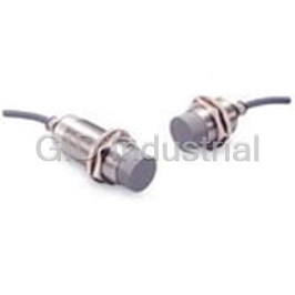
Inductive Power Coupler
B7APS1
Part Number
B7APS1
Price
Request Quote
Manufacturer
OMRON AUTOMATION
Lead Time
Request Quote
Category
Thermal Management » Misc Products
Specifications
Manufacturer
Omron Automation
Manufacturers Part #
B7APS1
Industry Aliases
B7AP-S1
Sub-Categories
Miscellaneous Tools and Supplies
Factory Pack Quantity
1
Datasheet

Extracted Text
Power Couplers B7AP CSM_B7AP_DS_E_3_1 Transmits Input Device ON/OFF Signals and Power. The Key to Effortless Wiring for Rotating and Moving Bodies. Be sure to read Safety Precautions on page 5. Features Transmit Multiple Switch Signals and Power Total Transmission Distance Up to 100 m to without Contact The transmission distance between Power Couplers without contact is 8±1.5 mm. The maximum transmission distance By connecting the B7AP Power Coupler between the B7A between the B7A Input Unit and B7A Output Unit is 100 m Input Unit and B7A Output Unit, it is possible to transmit (when transmitting power or signals). multiple switch signals without contact from input devices to controllers. When using the B7AP Power Coupler in this way, it is possible to transmit power via electromagnetic coupling, so a power supply for the Input Unit is not necessary. 8±1.5 mm B7A Output Unit B7A Input Unit B7A Output Unit Signal B7A Input Unit B7AP-S1 B7AP-M1 Power B7AP-S1 B7AP-M1 PLC or other controller Switch, Sensor, etc. Total length: 100 m Equipped with a Verification LED for Easy Transmission Also Possible When Settings Separated by a Non-metallic Object The B7AP-M1 is equipped with an operation indicator that Switch signals and power can be transmitted even when there lights the usable range during Coupler setup, allowing for is plastic, glass, wooden, or other non-metallic objects easy setup. between the Couplers (B7AP-S1/-M1). B7AP-S1 B7AP-M1 B7AP-S1 B7AP-M1 1 B7AP Usable in a Variety of Environments with Select Transmission Method Based on IP67 Environmental Resistance Application Conditions The Couplers have IP67 degree of protection, which allows When transmitting power and transmission signals, a them to be used in harsh environments that may expose them maximum of 10 points can be input simultaneously to the B7A to dust from glass, plastic or paper, or exposure to water. The Input Unit. Couplers can be used in a wide range of applications. (B7A Input Unit: Input Current 3.8 mA × 10 points = 38 mA) B7A Output Unit B7A Input Unit B7AP-S1 B7AP-M1 Power PLC or other Switch, Sensor, etc. Supply controller When transmitting only signals, a maximum of 16 points can be input to the B7A Input Unit. B7A Output Unit B7A Input Unit B7AP-S1 B7AP-M1 Power Power PLC or other Switch, Supply Supply controller Sensor, etc. Applications Turntable Transformation Robot Hand Pallet To B7A Proximity Sensor Output Unit Proximity Sensor B7AP B7A To B7A Power Input Unit Output Unit Couplers B7A B7AP B7AP Input Unit B7A Power Couplers Power Couplers To B7A Input Unit B7A Output Unit To B7A B7AP Input Unit Proximity Output Unit Power Couplers Sensor Ordering Information I/O transmission Classification Appearance Transmission distance (couplers) Model delay time M30 Stationary Unit B7AP-S1 * 8±1.5 mm Typical: 19.2 ms Max: 31 ms M30 Stationary Unit Moving Unit Moving Unit B7AP-M1 * The B7AP-S1 Power Coupler has a gauge that is used to adjust the transmission distance between the B7AP Power Couplers. 2 B7AP Ratings and Specifications Stationary Unit Transmission Specifications Moving Unit Specifications Item Model B7AP-S1 Item Model B7AP-M1 Transmission method Unidirectional, time-division multiplex Power supply 12 VDC±10%, 38 mA Note: Use the Moving Unit so that the total current consumption of all input Between Couplers Between B7AP-S1 and -M1: 8±1.5 mm Transmis- devices is 38 mA max. sion Between Input Unit Between B7A Input and Output Units: distance and Output Unit 100 m max. *1 Specifications Standard: 19.2 ms, Transmission delay time Model Item B7AP-S1 B7AP-M1 Maximum: 31 ms Power supply voltage Minimum Coupler interfacing time 0.3 s *2 24 VDC ±10, ripple (p-p): (operating voltage --- 10% max Minimum distance between Pow- range) 60 mm min. er Couplers mounted in parallel Current consumption --- 300 mA *1. The value is for when a power supply is provided only for the B7AP-S1. 100 MΩ min. (at 500 VDC) between each lead wire *2. Minimum Coupler interfacing time is the minimum time required for signal Insulation resistance and external parts and power transmission between the Power Couplers. 1,000 VAC, 50/60 Hz for 1 min between each lead Dielectric strength wire and external parts Engineering Data (Typical) Noise immunity Noise level: ±1.5 kV, pulse width: 100 ns/1 µs Operating: −10 to 55°C Transmission Range Ambient temperature Storage: −25 to 65°C 12 (with no icing or condensation) Operating/Storage: 35% to 95% (with no Ambient humidity condensation) 10 Vibration resistance 10 to 55 Hz, 1.5-mm double amplitude each in X, (destruction) Y, and Z directions 8 Shock resistance 2 500 m/s each in X, Y, and Z directions (destruction) 6 Degree of protection IEC IP67 Nut tightening 4 39 N·m X strength Pre-wired Models (Standard cable length: 2 m) 2 Y Connection method B Cable tensile strength: 49 N Angle offset from center Available zone B: 2° max. Weight (packed state) Approx. 300 g Approx. 230 g 0 −6 −4 −2 024 6 Distance between axes Y (mm) Contact your OMRON sales representative for further information. Connectable B7A Models (The 10-point and 16-point High-speed B7A Models cannot be connected.) B7AP Model Applicable B7A Link Terminal Max. I/O points (*1) Applicable input device (*3) B7A-R6B31 B7A-R6C31 B7A-R6F31 B7A-R6G31 B7A-R6A52 B7A-R6A33 B7AP-S1 (*2) --- B7A-R3A33 B7A-R3A33-M B7AS-R6B31 B7AM-6BS G70D-R6@@1-B7A B7AH-R6D53 B7A-T6@1 10 (16) Two-wire sensor, contact B7A-T6D2 10 (16) B7A-T6E3 10 (16) Contact B7A-T3E3 10 (16) B7AP-M1 B7A-T3E3-M 10 (16) B7AS-T6B1 10 (16) Two-wire sensor, contact B7AM-6BS 10 (16) B7AH-T6D3 16 CMOS input is supported *1. The maximum I/O points refers to the maximum I/O points handled simultaneously by the B7A Input and Output Units. Figures in parentheses indicate the maximum I/O points handled simultaneously by the B7A Input and Output Units each connected with an independent power supply. Refer to the Power Supplies page. The B7AH requires two types of power supplies (24 VDC and 5 VDC), so a power supply is required for each Unit. *2. The maximum I/O points are the same as the maximum input points of the B7A Input Unit connected to the B7AP-M1. *3. PLCs and three-wire sensors can be connected only if the B7A Input and Output Units are each connected with independent power supplies. Refer to the section on Power Supplies. 3 Transmission distance X (mm) B7AP Connection 24 VDC±10% Brown Brown Black Black SIG SIG Blue Blue B7A-R (Output Unit) B7A-T Input Unit B7AP-S1 B7AP-M1 Power Supplies • Signal and Power Transmission (with Power Supplied to B7AP-S1) Note 1. The thickness of the extension cable for Transmission distance: 8±1.5 mm the B7AP-S1 Power Coupler must be 24 VDC±10% 2 0.75 mm min. Brown Brown 2. No extension cable can be connected to Black Black the B7AP-M1 Power Coupler. Use the SIG SIG original 2-m cable connected to the Blue Blue B7AP-M1 Power Coupler. 2m 2 m B7A-R B7A-T B7AP-S1 B7AP-M1 (standard) 3. Refer to page 3, B7A Models for the Extension cable (standard) (Output Unit) (Input Unit) (96 m max.) maximum input points of the B7A Input Total length: 100 m max. Unit. 4. No PLC or three-wire sensor can be connected to the B7A Input Unit. • Signal Transmission Only (with Power Supplied to B7AP-S1 and B7AP-M1) Note 1. The thickness of the extension cable for Open (no connection) Transmission distance: 8±1.5 mm the B7AP-S1 or B7AP-M1 Power Coupler B7A-T 12 to 2 24 VDC±10% must be 0.75 mm min. 24 VDC (Input Unit) Brown Brown 2. For transmitting signals only, the brown ±10% lead wire of the B7AP-M1 Power Coupler Black Black SIG SIG must not be used. Insulate the brown Blue Blue lead wire with insulation tape so that the 2 m 2 m brown wire will not come in contact with B7A-R (standard) B7AP-S1 B7AP-M1 (standard) Extension cable Extension any lead wire. (Output Unit) (96 m max.) cable 3. The maximum input points of the B7A Total length: 500 m max. (400 m max.) Input Unit are available. 4. PLCs and three-wire sensors can be connected to the B7A Input Unit. Indicators B7AP-S1 Indicators Function Operation indicator Lit green when power is supplied to the Power Coupler. Power indicator Not lit when power is not supplied to the Power Coupler. Lit green when the Power Couplers are B7AP-M1 properly set for power transmission at a transmission distance of 8±1.5 mm. Operation indicator Operation indicator Not lit when the Power Couplers are not properly set for power transmission, or the Power Coupler has excessive loads. 4 B7AP Safety Precautions WARNING This product is not designed or rated for 6. Wire the cables of the B7AP-S1and B7AP-M1 Power ensuring safety of persons. Couplers through independent metal conduits to prevent Do not use it for such purposes. the Power Couplers from being influenced by noise if there are power or high-tension lines nearby. Test the Power Couplers and make sure that the Power Couplers operate Precautions for Safe Use normally before they are put in actual operation. Be careful when touching the B7AP-S1 (Stationary Unit) Power Coupler during operation because the surface Correct Incorrect Metal conduit temperature of the B7AP-S1 Power Coupler will rise approximately 20°C after the B7AP-S1 Power Coupler starts power transmission. The surface temperature varies with the load of the sensing device connected to the B7AP-M1 (Moving Unit) Power Coupler and the transmission distance. Power or high-tension line Precautions for Correct Use 7. Do not subject the head of the B7AP-S1 or B7AP-M1 Power Coupler to excessive shock with hard objects. Do not use this product under ambient conditions that exceed the ratings. Handling 1. Use the B7AP-S1 and B7AP-M1 Power Couplers with the available B7A Link Terminals shown in Connectable B7A Models on page 3. 8. Do not use the B7AP-S1 or B7AP-M1 Power Coupler The M7E-12@@ Display Unit, M7E-20@@ Display Unit, outdoors unless it is properly protected. B7A-T10M2, B7AC-T10A1, and 16-point High-speed model cannot be connected to the Power Controller. 2. Use the LOAD-OFF model for the B7A Output Unit to be connected to the B7AP-S1 Stationary Unit. The LOAD-OFF model turns OFF all outputs when there is no transmission between the B7AP Power Couplers. 3. The B7AP Power Couplers must be separated by at least 30 mm to prevent transmission. 30 mm min. 9. Degree of Protection The B7AP-S1 and B7AP-M1 Power Couplers are products meeting the requirements of IP67. (They are not fully sealed water-tight models.) The B7AP-S1 or B7AP-M1 Power Coupler cannot be, however, used in water or oil. B7AP-S1 B7AP-M1 10. Keep the heads of the B7AP-S1 and B7AP-M1 Power 4. Do not supply power to the B7AP-S1 or B7AP-M1 Power Couplers free from dust, otherwise improper signal or Coupler while connecting the Power Couplers to the B7A power transmission may result between the Power Link Terminals. Connect the Power Couplers to the B7A Couplers. Link Terminals correctly, otherwise the internal circuits of 11. When complying with UL standards, install a device the Power Couplers may be damaged. between the external power supply and the B7AP-S1 that 5. The SIG terminal must not contact with the power supply limits the current to 5 A. terminals, otherwise the internal element may be damaged and normal transmission may not be possible. Mounting Use nuts and serrated toothed washers and tighten the nuts. Brown (+) The torque is 39 N·m maximum. The mounting position will Black (SIG) Correct SIG change and improper signal or power transmission may result Blue (−) between the Power Couplers if the nuts are not tightened B7A properly. Contact Brown (+) 39 N·m max. Black (SIG) Incorrect SIG Blue (−) B7A Black (+) Brown (SIG) SIG Incorrect Blue (−) B7A 5 B7AP Transmission Distance for Stable Signal and Power Effects of Surrounding Metal Transmission The B7AP Power Coupler may malfunction when affected by Use the gauge to adjust the transmission distance to 8 mm, surrounding metal. When mounting the B7AP within a metal make sure that the green operation indicator of the B7AP-M1 panel, ensure that the clearances given in the following table Power Coupler is lit, and the B7A Output Unit has no error are maintained. Be sure to check in advance that the B7AP output before operating the Power Couplers. operates properly. 8 mm Gauge Operation indicator n d dia. D L B7AP-S1 B7AP-M1 (Unit: mm) Dimensions Model B7AP-S1 B7AP-M1 Monitoring Transmission Status L20 20 Judge from the power supply/error indicator and error output d 60 dia. 60 dia. of the B7A Output Unit whether the B7AP-S1 and B7AP-M1 D20 20 Power Couplers are facing each other properly. (Use the B7A n60 60 Output Unit power and error indicator, and error terminal.) The error output of the B7A Output Unit will be ON when the Maintenance B7AP-S1 and B7AP-M1 Power Couplers are not facing each As with other control devices, regularly check the following to other properly. ensure the long-term stable operation of the B7AP-S1 and Minimum Distance between Power Couplers Mounted in B7AP-M1 Power Couplers. Parallel 1. The mounting positions, misalignment, tightening of the When mounting the B7AP-S1 and B7AP-M1 Power Couplers mounting nuts, and warping. in parallel, refer to the following table. Keep at least the 2. The tightening, contacts, and breaking of the lead wires. specified minimum distance between adjacent Power 3. Dust accumulation on the heads. Couplers for proper heat radiation by considering the 4. The ambient operating temperature and other operating temperature rise (approximately 20°C) of the B7AP-S1 Power conditions. Couplers in operation. 5. The transmission distance. L (Unit: mm) Dimensions Model B7AP-S1 B7AP-M1 L60 60 6 B7AP (Unit: mm) Dimensions Unless otherwise specified, the tolerance class IT16 is used for dimensions in this data sheet. B7AP-S1 98 Mounting Holes 85.3 42 dia. 80 Power indicator +0.5 36 30.5 dia. Toothed washer 0 13 10 6-dia. round vinyl-insulated cable 2 (0.5 mm ) Standard length: 2 m 27.3 dia. M30 × 1.5 Two, 5 clamping nuts B7AP-M1 61 Mounting Holes 48.3 42 dia. 43 Operation indicator +0.5 36 13 30.5 dia. Toothed washer 0 6-dia. round vinyl-insulated cable 2 (0.5 mm ) Standard length: 2 m 27.3 dia. M30 × 1.5 Two, 5 clamping nuts In the interest of product improvement, specifications are subject to change without notice. 7 Read and Understand This Catalog Please read and understand this catalog before purchasing the products. Please consult your OMRON representative if you have any questions or comments. Warranty and Limitations of Liability WARRANTY OMRON's exclusive warranty is that the products are free from defects in materials and workmanship for a period of one year (or other period if specified) from date of sale by OMRON. OMRON MAKES NO WARRANTY OR REPRESENTATION, EXPRESS OR IMPLIED, REGARDING NON-INFRINGEMENT, MERCHANTABILITY, OR FITNESS FOR PARTICULAR PURPOSE OF THE PRODUCTS. ANY BUYER OR USER ACKNOWLEDGES THAT THE BUYER OR USER ALONE HAS DETERMINED THAT THE PRODUCTS WILL SUITABLY MEET THE REQUIREMENTS OF THEIR INTENDED USE. OMRON DISCLAIMS ALL OTHER WARRANTIES, EXPRESS OR IMPLIED. LIMITATIONS OF LIABILITY OMRON SHALL NOT BE RESPONSIBLE FOR SPECIAL, INDIRECT, OR CONSEQUENTIAL DAMAGES, LOSS OF PROFITS OR COMMERCIAL LOSS IN ANY WAY CONNECTED WITH THE PRODUCTS, WHETHER SUCH CLAIM IS BASED ON CONTRACT, WARRANTY, NEGLIGENCE, OR STRICT LIABILITY. In no event shall the responsibility of OMRON for any act exceed the individual price of the product on which liability is asserted. IN NO EVENT SHALL OMRON BE RESPONSIBLE FOR WARRANTY, REPAIR, OR OTHER CLAIMS REGARDING THE PRODUCTS UNLESS OMRON'S ANALYSIS CONFIRMS THAT THE PRODUCTS WERE PROPERLY HANDLED, STORED, INSTALLED, AND MAINTAINED AND NOT SUBJECT TO CONTAMINATION, ABUSE, MISUSE, OR INAPPROPRIATE MODIFICATION OR REPAIR. Application Considerations SUITABILITY FOR USE OMRON shall not be responsible for conformity with any standards, codes, or regulations that apply to the combination of products in the customer's application or use of the products. At the customer's request, OMRON will provide applicable third party certification documents identifying ratings and limitations of use that apply to the products. This information by itself is not sufficient for a complete determination of the suitability of the products in combination with the end product, machine, system, or other application or use. The following are some examples of applications for which particular attention must be given. This is not intended to be an exhaustive list of all possible uses of the products, nor is it intended to imply that the uses listed may be suitable for the products: Outdoor use, uses involving potential chemical contamination or electrical interference, or conditions or uses not described in this catalog. Nuclear energy control systems, combustion systems, railroad systems, aviation systems, medical equipment, amusement machines, vehicles, safety equipment, and installations subject to separate industry or government regulations. Systems, machines, and equipment that could present a risk to life or property. Please know and observe all prohibitions of use applicable to the products. NEVER USE THE PRODUCTS FOR AN APPLICATION INVOLVING SERIOUS RISK TO LIFE OR PROPERTY WITHOUT ENSURING THAT THE SYSTEM AS A WHOLE HAS BEEN DESIGNED TO ADDRESS THE RISKS, AND THAT THE OMRON PRODUCTS ARE PROPERLY RATED AND INSTALLED FOR THE INTENDED USE WITHIN THE OVERALL EQUIPMENT OR SYSTEM. PROGRAMMABLE PRODUCTS OMRON shall not be responsible for the user's programming of a programmable product, or any consequence thereof. Disclaimers CHANGE IN SPECIFICATIONS Product specifications and accessories may be changed at any time based on improvements and other reasons. It is our practice to change model numbers when published ratings or features are changed, or when significant construction changes are made. However, some specifications of the products may be changed without any notice. When in doubt, special model numbers may be assigned to fix or establish key specifications for your application on your request. Please consult with your OMRON representative at any time to confirm actual specifications of purchased products. DIMENSIONS AND WEIGHTS Dimensions and weights are nominal and are not to be used for manufacturing purposes, even when tolerances are shown. PERFORMANCE DATA Performance data given in this catalog is provided as a guide for the user in determining suitability and does not constitute a warranty. It may represent the result of OMRON’s test conditions, and the users must correlate it to actual application requirements. Actual performance is subject to the OMRON Warranty and Limitations of Liability. ERRORS AND OMISSIONS The information in this document has been carefully checked and is believed to be accurate; however, no responsibility is assumed for clerical, typographical, or proofreading errors, or omissions. 2011.7 In the interest of product improvement, specifications are subject to change without notice. OMRON Corporation Industrial Automation Company http://www.ia.omron.com/ (c)Copyright OMRON Corporation 2011 All Right Reserved.
Frequently asked questions
How does Electronics Finder differ from its competitors?

Is there a warranty for the B7APS1?
Which carrier will Electronics Finder use to ship my parts?
Can I buy parts from Electronics Finder if I am outside the USA?
Which payment methods does Electronics Finder accept?
Why buy from GID?

Quality
We are industry veterans who take pride in our work

Protection
Avoid the dangers of risky trading in the gray market

Access
Our network of suppliers is ready and at your disposal

Savings
Maintain legacy systems to prevent costly downtime

Speed
Time is of the essence, and we are respectful of yours
Related Products
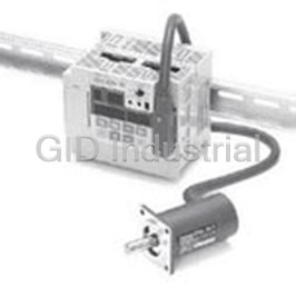
Cam Positioners With High Speed and High Precision Double Machine Productivity 3F88L160
Cam Positioners With High Speed and High Precision Double Machine Productivity 3F88L162
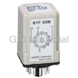
Controllers SURGE SUPRESSOR 61F-03B
Controllers SURGE SUPRESSOR 61F-04B
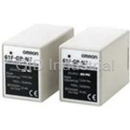
Conductive Level Controller 61F-GP-N2220VAC
Conductive Level Controller 61F-GP-N224VAC
Request a Quote

The quote request has been received
Close

Facing challenges or have inquiries? Feel free to contact us!
Call Us +1-469-283-2440
What they say about us
FANTASTIC RESOURCE
One of our top priorities is maintaining our business with precision, and we are constantly looking for affiliates that can help us achieve our goal. With the aid of GID Industrial, our obsolete product management has never been more efficient. They have been a great resource to our company, and have quickly become a go-to supplier on our list!
Bucher Emhart Glass
EXCELLENT SERVICE
With our strict fundamentals and high expectations, we were surprised when we came across GID Industrial and their competitive pricing. When we approached them with our issue, they were incredibly confident in being able to provide us with a seamless solution at the best price for us. GID Industrial quickly understood our needs and provided us with excellent service, as well as fully tested product to ensure what we received would be the right fit for our company.
Fuji
HARD TO FIND A BETTER PROVIDER
Our company provides services to aid in the manufacture of technological products, such as semiconductors and flat panel displays, and often searching for distributors of obsolete product we require can waste time and money. Finding GID Industrial proved to be a great asset to our company, with cost effective solutions and superior knowledge on all of their materials, it’d be hard to find a better provider of obsolete or hard to find products.
Applied Materials
CONSISTENTLY DELIVERS QUALITY SOLUTIONS
Over the years, the equipment used in our company becomes discontinued, but they’re still of great use to us and our customers. Once these products are no longer available through the manufacturer, finding a reliable, quick supplier is a necessity, and luckily for us, GID Industrial has provided the most trustworthy, quality solutions to our obsolete component needs.
Nidec Vamco
TERRIFIC RESOURCE
This company has been a terrific help to us (I work for Trican Well Service) in sourcing the Micron Ram Memory we needed for our Siemens computers. Great service! And great pricing! I know when the product is shipping and when it will arrive, all the way through the ordering process.
Trican Well Service
GO TO SOURCE
When I can't find an obsolete part, I first call GID and they'll come up with my parts every time. Great customer service and follow up as well. Scott emails me from time to time to touch base and see if we're having trouble finding something.....which is often with our 25 yr old equipment.
ConAgra Foods