

 Manufacturers
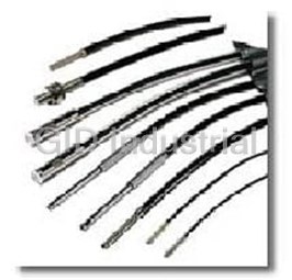
OMRON AUTOMATION E32-TC200
Description
Photoelectric Sensor Thru-beam 1m 2-Pin
E32-TC200
Part Number
E32-TC200
Price
Request Quote
Manufacturer
OMRON AUTOMATION
Lead Time
Request Quote
Category
Sensors and Transducers » Photoelectric Sensor
Specifications
Manufacturer
Omron Automation
Manufacturers Part #
E32-TC200
Industry Aliases
E32-TC200
Sub-Category
Photoelectric Sensors
Factory Pack Quantity
1
Datasheet

Extracted Text
Fiber Sensors Best Selection Catalog OMRON's Fiber Sensors continue to support an increasing range of applications. This catalog brings you the latest information on our Fiber Units. E32-series Fiber Units Amplifier Units E3X-DA-S/-MDA Series E3X-NA Series Detection with Increased Standard Models Standard Models Special-beam Models First, Our Standard Lineup First, Our Standard Lineup P6 Reliability These Fibers Units can be used in a variety of applications, such as detecting the presence of workpieces and positioning. A Wide Variety of Shapes for Adapting to Different Installation Locations Space Savings and Simple Mounting Flat Models Choose the model that suits the installation space from a Flat models that allow simple wide variety of shapes and sizes (7 shapes, in standard screw mounting and or small sizes). straightforward wiring have been added to the lineup. Using these models eliminates the problem of fibers getting caught on surrounding objects. Flat model High Resistance to External Environment- resistive Models Conditions with Fiber Detect Workpieces in Tight Spaces Custom-produced Sleeves Models with sleeves allow Screw-shaped Flat Equipped with sleeve Cylindrical detection in tight spaces. We will perform the time-consuming task of fashioning the sleeve, with a length and bends to suit the space (except for ultrafine Models with sleeves sleeves). Flexible, Pliable Fiber That Can Be Handled Like Wire Fiber Units for the Food-packaging, Application- We have developed a broad range of fibers to meet a wide Length Can Be Specified in 1-m Units variety of needs. Multicore (flexible) fiber is a new type of specific Models Saving Energy and Work Semiconductor, and FPD Industries standard fiber that can be used like wire without worrying We will produce fiber of the required length (in meter about the bending radius. We have also produced fiber that units). For large-scale installations, specifications of up will not break when used in moving parts and fiber that is not degraded by contact with oil. to 20 m can be handled. (Specifications of 0.3 m and 0.5 m are also possible.) Conventional fiber Flexible fiber You will certainly appreciate the ease of use that flexible fiber ensures. Detection with Increased Detection with Increased Standard Models Special-beam Models Special-beam Models First, Our Standard Lineup Reliability Reliability P10 A variety of heads incorporating the latest optical technology makes it possible to solve common problems related to detection and to increase reliability. ■ Resistant to dust and dirt ■ Capable of detecting small workpieces ■ Resistant to workpiece vibration Use these models to handle Area-sensing models Limited-reflective High-power models Small-spot models unstable detection conditions. E32-T16J models E32-T17L E32-C42+ E32-L24L E39-F3A High Resistance to External High Resistance to External Environment- Environment- P14 resistive Models resistive Models Conditions with Fiber Conditions with Fiber We have developed model variations for adapting to a variety of environmental conditions. These models enable detection in high-temperature environments and vacuums. ■ High-temperature environments ■ Environments subject to the splattering of chemicals ■ Vacuums Use these models to handle Heat-resistant models Chemical-resistant models applications in special environments. Fiber Units for the Food-packaging, Fiber Units for the Food-packaging, Application- Application- P16 specific Models specific Models Semiconductor, and FPD Industries Semiconductor, and FPD Industries These models, which were developed for specific applications, offer top-quality detection performance. ■ Label detection ■ Liquid-level detection ■ Alignment and mapping of glass substrates ■ Wafer mapping Use these models for Label-detection models Alignment-check models Liquid-level detection models specific applications. E32-G14 E32-L16 E32-D36T Selection Guide Fiber Units We have developed model variations for handling a broad range of applications. Amplifier Units Fiber Units ■ High-temperature environ- Environmental ments (up to 400ºC) Special environments ■ Environments subject to scat- Detection conditions Standard environments tering of chemicals and oil conditions ■ Vacuum environments Standard Models P.6 Environment-resistive Models P.14 ■ Workpiece presence Standard ■ Positioning detection ■ Level differences and marks Workpiece Positioning Level Marks Workpiece Positioning Level presence differences presence difference Special-beam Models P.10 ■ Long-distance sensing, resistance to Special- dust and dirt ■ Small beam, resistance to rattling beam ■ Detection of transparent objects High power Small spot Area sensing Retroreflective sensing Application-specific Models P.16 ■ Labels ■ Liquid level Application- ■ Alignment and mapping of glass sub- specific strates ■ Wafer mapping Labels Liquid level Alignment Mapping Amplifier Units Type Digital Manual Appearance 2-channel models 48 µs, 1 ms, or 4 ms 100 µs, 1 ms, or 4 ms 200 µs Response (high-speed models: 20 µs) time (2-output models: 80 µs, 1 ms, or 4 ms) Light source Red, green, blue, or infrared LED Red or green LED Dual display (including digital, bar, percent, and hold display functions) LED bar display (5 levels) Threshold adjustment performed manually or by teaching 8-turn sensitivity adjuster OFF-delay, ON-delay, one-shot timer (adjustable from 1 ms to 5 s) OFF delay timer (fixed at 40 ms) Function Advanced-function models are Water-resistant models are available. available (2-output/input models). E3X-DA@-S E3X-MDA@ E3X-NA@ Models E3X-DA@TW-S (2-output model) E3X-NA@F (high-speed model) E3X-DA@RM-S (input model) E3X-NA@V (water-resistant model) 4 CONTENTS ■ Selection Guide . . . . . . . . . . . . . . . . . . . . . . . . . . . . . . . . . . . . . . . . . . . . . . . . . . . . . P4 ■ Overview of Features, Applications, and Variations Standard Models Flexible (New Standard) . . . . . . . . . . . . . . . . . . P6 Standard . . . . . . . . . . . . . . . . . . . . . . . . . . . . . . . . P6 Break-resistant . . . . . . . . . . . . . . . . . . . . . . . . . . . P6 Fluorine Coating . . . . . . . . . . . . . . . . . . . . . . . . . . P7 Special-beam Models Long Distance, High Power . . . . . . . . . . . . . . P10 Ultracompact, Ultrafine Sleeve . . . . . . . . . . . . . . P10 Coaxial, Small Spot . . . . . . . . . . . . . . . . . . . . . . . P11 Fine Beam (Narrow Vision Field) . . . . . . . . . . . . P12 Area Sensing. . . . . . . . . . . . . . . . . . . . . . . . . . . . P12 Retroreflective . . . . . . . . . . . . . . . . . . . . . . . . . . . P13 Limited-reflective . . . . . . . . . . . . . . . . . . . . . . . . . P13 Environment-resistive Models Heat-resistant . . . . . . . . . . . . . . . . . . . . . . . . . . P14 Chemical-resistant. . . . . . . . . . . . . . . . . . . . . . . . P14 Vacuum-resistant . . . . . . . . . . . . . . . . . . . . . . . . P15 Application-specific Models Label Detection. . . . . . . . . . . . . . . . . . . . . . . . . P16 Liquid-level Detection . . . . . . . . . . . . . . . . . . . . . P16 Glass-substrate Alignment . . . . . . . . . . . . . . . . . P17 Glass-substrate Mapping . . . . . . . . . . . . . . . . . . P17 Water Mapping . . . . . . . . . . . . . . . . . . . . . . . . . . P18 ■ Ordering Information Through-beam Fiber Units . . . . . . . . . . . . . . . . . . . . . . . . . . . . . . . . . . . . . . . . . . . . . . P19 Fiber Units with Reflective Sensors . . . . . . . . . . . . . . . . . . . . . . . . . . . . . . . . . . . . . . . P25 Application-specific Fiber Units . . . . . . . . . . . . . . . . . . . . . . . . . . . . . . . . . . . . . . . . . . P30 ■ Ratings/Characteristics. . . . . . . . . . . . . . . . . . . . . . . . . . . . . . . . . . . . . . . . . . . . . P34 ■ Dimensions Through-beam Fiber Units . . . . . . . . . . . . . . . . . . . . . . . . . . . . . . . . . . . . . . . . . . . . . . P36 Fiber Units with Reflective Sensors . . . . . . . . . . . . . . . . . . . . . . . . . . . . . . . . . . . . . . . P42 Application-specific Fiber Units . . . . . . . . . . . . . . . . . . . . . . . . . . . . . . . . . . . . . . . . . . P47 ■ Precautions. . . . . . . . . . . . . . . . . . . . . . . . . . . . . . . . . . . . . . . . . . . . . . . . . . . . . . . . . P51 5 Features/Applications Standard Models R Flexible (New Standard) ■ Feature: Multicore (Flexible) Fibers Perform wiring without worrying about the bending radius. Choose the model to suit the installation space from a variety of shapes. Cores Cladding Flexible fiber Conventional fiber A large number of ultrafine cores are all surrounded by cladding. As a result, the fiber is flexible and can be bent without significantly reducing the light intensity. This helps solve problems, such as fiber being broken by get- ting caught on other objects. ■ Ratings/Characteristics Min. sensing 0.005-mm dia. object Min. bending 1 mm radius Ambient tem- −40°C to 70°C (no icing or condensation) Light intensity affected by bends in fiber perature Fewer problems Fiber broken by getting caught on sur- rounding objects Fiber material Plastic Standard ■ Feature: Flat Models Flat models, which allow simple attachment and wiring, Choose the model to suit the installation space have been added to the lineup. Choose the model to suit from a variety of shapes. the installation space from 3 sensing directions and 2 New flat models allow space savings and simple sizes, standard and small. installation. ■ Ratings/Characteristics Min. sensing 0.005-mm dia. object Min. bending 10 or 25 mm* radius Ambient tem- −40°C to 70°C (no icing or condensation) perature Screw-shaped Cylindrical Flat Equipped with sleeve Fiber material Plastic *Depends on the fiber diameter. B Break-resistant ■ Feature: Bundle Fibers Bundle-fiber models can be used for moving parts. Capable of withstanding at least one million re- The Fiber Units contain a large number of independent peated bends (in typical applications). fine fibers, ensuring a high degree of flexibility. ■ Ratings/Characteristics Min. sensing 0.005-mm dia. object Min. bending 4 mm (withstands repeated bending) radius Ambient tem- −40°C to 70°C (no icing or condensation) perature Fiber material Plastic 6 ì¡í²ÅEÉAÉvÉäÉPÅ[ÉVÉáÉì Standard Models U Fluorine Coating ■ Feature: Fluorine Coating Fiber degradation due to oil is prevented using a fluo- roresin coating. (Cross section) Free cutting is possible with cutter provided. Fluororesin coating Oil is blocked! Fluororesin is used as the sheath material to prevent fi- ber degradation resulting from oil adhesion. Note: The tip of the head is not chemical-resistant. ■ Ratings/Characteristics Min. sensing 0.005-mm dia. object Min. bending 4 mm radius Ambient tem- −40°C to 70°C (with no icing or condensation) perature Fiber material Plastic This customization/delivery service applies to standard models. It is (Fiber Length, Sleeve Fiber Customization Service aimed at reducing industrial waste and simplifying the installation Length, and Bends) procedure. ■ Fiber Length vs. Sensing Distance Fiber Length Through-beam Fiber Units Fiber Units with Reflective Sensors (Fiber length of 2 m corresponds to (Fiber length of 2 m corresponds to 100%.) 100%.) ■ Applicable Models 100 100 Standard models 80 80 ■ Model Number Used for Ordering 60 60 Standard model number + Fiber length Fiber length: 0.3 m, 0.5 m, or any length from 40 40 1 to 20 m (in 1-m units) 20 20 0 2 5 10 15 20 0 2 5 10 15 20 Fiber length (m) Fiber length (m) Sleeve Length and Bends ■ Model Number Used When Changing Only the Sleeve Length ■ Applicable Models L E32-TC200B/E32-TC200F E32-DC200B/E32-DC200F Model: E32- *1C200*2 -S*3 The E32-DC200B cannot be bent. ■ Model Number Used When Changing the Sleeve Length and Bends Total length Total length L2 L1 R R Model Numbers Incorporating the Bending Radius, R, and Dimensions L1 and L2 Specifying L1 Only Specifying L2 Only (Units: mm) (Units: mm) Bending Bending L1 (±1) Model number L2 (±1) Model number radius radius 10 E32- *1 C200 *2 -S *3 A1 5 E32- *1 C200 *2 -S *3 A3 R5 R5 15 E32- *1 C200 *2 -S *3 A2 10 E32- *1 C200 *2 -S *3 A4 12.5 7.5 E32- *1 C200 *2 -S *3 B1 E32- *1 C200 *2 -S *3 B3 R7.5 R7.5 17.5 17.5 E32- *1 C200 *2 -S *3 B2 E32- *1 C200 *2 -S *3 B4 15 E32- *1 C200 *2 -S *3 C1 10 E32- *1 C200 *2 -S *3 C3 R10 R10 20 E32- *1 C200 *2 -S *3 C2 20 E32- *1 C200 *2 -S *3 C4 17.5 E32- *1 C200 *2 -S *3 D1 12.5 E32- *1 C200 *2 -S *3 D3 R12.5 R12.5 22.5 E32- *1 C200 *2 -S *3 D2 22.5 E32- *1 C200 *2 -S *3 D4 *1: Insert "T" for Through-beam Fiber Units and "D" for Fiber Units with Reflective Sensors. *2: Insert the "B" or "F" that appears at the end of the original model number. *3: Insert "50" if the total length is 50 mm. The total length must not exceed 120 mm. 7 Sensing distance (%) Sensing distance (%) Features/Applications Standard Models Sensing distance (mm) Overview of Model Variations (See note 1.) Through-beam Fiber Units Model Type Flexible (New Standard) Standard Break-resistant Fluorine coating (See note 2.) U R B (Cross section) Fluororesin coating Shape of head Flexible and pliable Withstands repeated Cable protected against bending oil Screw-shaped M4 530 760 680 680 (top-view) E32-T11R E32-TC200 E32-T11 E32-T11U M3 130 220 200 E32-T21R E32-TC200E E32-T21 M4 530 760 (with sleeve) (1.2-dia. sleeve) E32-TC200BR E32-TC200B M3 130 220 (0.9-dia. sleeve) E32-TC200FR E32-TC200F 3 dia. 530 760 680 Cylindrical (top-view) E32-T12R E32-T12 E32-T12B 1.5 dia. 130 220 200 E32-T22R E32-T222 E32-T22B 3 dia. 210 460 (side-view) E32-T14LR E32-T14L 1 dia. 50 130 E32-T24R E32-T24 Flat 15 × 8 × 3 530 760 680 (top-view) E32-T15XR E32-T15X E32-T15XB 12 × 7 × 2 130 220 150 E32-T25XR E32-T25X E32-T25XB 15 × 8 × 3210 460 (side-view) E32-T15YR E32-T15Y 12 × 7 × 250 130 E32-T25YR E32-T25Y 15 × 8 × 3210 460 (flat-view) E32-T15ZR E32-T15Z 12 × 7 × 250 130 E32-T25ZR E32-T25Z Note 1. The sensing distances apply for use in combination with the E3X-DA-S Amplifier Unit (general-purpose, standard mode). 2. These symbols are defined as follows. : Flexible fiber, : Bendable fiber, : Fluorine-coated fiber. R B U 8 ì¡í²ÅEÉAÉvÉäÉPÅ[ÉVÉáÉì Standard Models Sensing distance (mm) Overview of Model Variations (See note 1) Model Fiber Units with Reflective Sensors Type Flexible (New Standard) Standard Break-resistant Fluorine coating (See note 2.) U R B (Cross section) Fluororesin coating Shape of head Flexible and pliable Withstands repeated Cable protected against bending oil M6 170 300 170 170 Screw-shaped (top-view) E32-D11R E32-DC200 E32-D11 E32-D11U M3 30 80 30 E32-D21R E32-DC200E E32-D21 M6 170 300 (with sleeve) (2.5-dia. sleeve) E32-DC200BR E32-DC200B M3 30 80 (1.2-dia. sleeve) E32-DC200FR E32-DC200F Cylindrical 3 dia. 170 230 70 (top-view) E32-D12R E32-D12 E32-D221B 3 dia. 30 80 30 (1.5 dia.) E32-D22R E32-D22 E32-D22B 6 dia. 45 110 (side-view) E32-D14LR E32-D14L 2 dia. 15 30 E32-D24R E32-D24 15 × 10 × 3 170 300 170 Flat (top-view) E32-D15XR E32-D15X E32-D15XB 12 × 7 × 230 80 50 E32-D25X E32-D25X E32-D25XB 15 × 10 × 3 40 100 (side-view) E32-D15YR E32-D15Y 12 × 8 × 28 20 E32-D25YR E32-D25Y 15 × 10 × 3 40 100 (flat-view) E32-D15ZR E32-D15Z 12 × 8 × 28 20 E32-D25ZR E32-D25Z Note 1. The sensing distances apply for use in combination with the E3X-DA-S Amplifier Unit (general-purpose, standard mode). 2. These symbols are defined as follows. : Flexible fiber, : Bendable fiber, : Fluorine-coated fiber. R B U 9 Features/Applications Special-beam Models Long Distance, High Power ■ Applications • Powerful beam reduces influence of dust and dirt. Long sensing distance enables use in large-scale Detecting parts inside (trans- Detecting workpieces in lucent) containers coating processes installations. E32-T11L E32-T17L ■ Ratings/Characteristics Ambient tem- −40°C to 70°C (no icing or condensation) perature E32-T14 Fiber material Plastic ■ Overview of Model Variations Type Features Shape, sensing distance (mm)* Model number 20,000 E32-T17L Equipped with large lens 3,400 E32-T14 Side-view, screw mounting 1,330 E32-T11L M4 screw 700 E32-D16 Equipped with large lens M6 screw 400 E32-D11L Ultracompact, Ultrafine Sleeve ■ Applications Ultracompact head can be installed in tight spaces. Ultrafine sleeve ensures reliable detection of small Alignment Detection of terminals objects, such as electronic components. inspections E32-D33 1 dia. E32-T33-S5 3 dia. 0.22 ■ Ratings/Characteristics dia. 3 dia. E32-T223R Min. sensing 0.005-mm dia. object 0.5 dia. Ambient tem- −40°C to 70°C (no icing or condensation) perature E32-T334-S5 Material Plastic E32-D33 ■ Overview of Model Variations Type Features Shape, sensing distance (mm)* Model number 1-dia. cylinder 130 E32-T223R 0.5-dia. sleeve (0.25-dia. opening) 44 E32-T33-S5 0.22-dia. sleeve (0.1-dia. opening) 5 E32-T334-S5 0.8-dia. sleeve E32-D33 16 0.5-dia. sleeve E32-D331 3 *The sensing distances apply for use in combination with the E3X-DA-S Amplifier Unit (general-purpose, standard mode). 10 Refle- Refle- Through-beam Through-beam ctive ctive ì¡í²ÅEÉAÉvÉäÉPÅ[ÉVÉáÉì Special-beam Models Coaxial, Small Spot ■ Applications Small spot diameter (0.1 mm min. in diameter) enables the reliable detection of small workpieces. Detecting of CDs Use of red light ensures easy visual recognition and simple positioning. E32-C31+ E39-F3C ■ Ratings/Characteristics Min. sensing 0.005-mm dia. object Ambient tem- E32-C42+ −40°C to 70°C (no icing or condensation) perature E39-F3A Fiber material Plastic ■ Overview of Model Variations Type Features Shape, sensing distance (mm)* Model number 300 Coaxial, M6 screw E32-CC200 150 Coaxial, 3-dia. cylinder E32-D32L E32-C41+ Small spot 0.1-dia. spot at a distance of 7 mm E39-F3A-5 Spot diameter variable in the range E32-C42+ Small variable spot 0.1 to 0.6 mm at distances in the E39-F3A range 6 to 15 mm E32-C31+ Long distance, small spot 0.5-dia. spot at 17 mm E39-F3B Spot diameter of 4 mm max. at E32-C31+ Long distance, parallel light distances in the range 0 to 20 mm E39-F3C *The sensing distances apply for use in combination with the E3X-DA-S Amplifier Unit (general-purpose, standard mode). 11 mm 6 mm 7 mm 15 mm 20 mm 17 mm 0.1 mm dia. spot E32-C41+ Variable from E39-F3A-5 4 mm dia. 0.1 to 0.6 dia. 0.5 mm dia. E32-C31+ E32-C42+ E32-C31+ E39-F3C E39-F3A E39-F3B 11 Coaxial, reflective Features/Applications Special-beam Models Fine Beam (Narrow Vision Field) ■ Applications Fine beam reduces unwanted light in surrounding area. Alignment inspection Powerful beam allows use in applications requiring a long sensing distance. of orientation flats Approx. Approx. 6° 60° E32-T22S ■ Ratings/Characteristics Min. bending 10 mm radius Ambient tem- −40°C to 70°C (no icing or condensation) 1300 mm perature E32-T24S Fiber material Plastic ■ Overview of Model Variations Type Features Shape, sensing distance (mm)* Model number Top view 1,900 E32-T22S Side view 1,300 E32-T24S Area Sensing These Fiber Units ensure greater reliability with the de- ■ Applications tection of position inconsistencies in passing workpiec- Detecting chips on film es and the presence of workpieces with holes. Detecting passage of Wide sensing bands of 11 and 30 mm (through-beam candies models) enable the detection of large position incon- sistencies. 11 mm E32-T16WR E32-T16PR ■ Ratings/Characteristics 30 mm Ambient tem- −40°C to 70°C (no icing or condensation) perature E32-T16W@ only: −25°C to 55°C Fiber material Plastic E32-T16WR E32-D36P1 ■ Overview of Model Variations Type Features Shape, sensing distance (mm)* Model number Sensing width: 11 mm 840 E32-T16PR Sensing width: 11 mm 750 E32-T16JR Flat-view Sensing width: 30 mm 1,300 E32-T16WR Beam width: 11 mm 150 E32-D36P1 *The sensing distances apply for use in combination with the E3X-DA-S Amplifier Unit (general-purpose, standard mode). 12 Refle- Through-beam Through-beam ctive ì¡í²ÅEÉAÉvÉäÉPÅ[ÉVÉáÉì Special-beam Models Retroreflective The return optical path ensures that more light is in- ■ Applications terrupted by transparent workpieces than with Detecting through-beam models. translucent Equipped with MSR function to eliminate light reflect- medicine E32-R21 ■ Ratings/Characteristics E32-R21: −40°C to 70°C Ambient tem- E32-R16: −25°C to 55°C perature (with no icing or condensation) Fiber material Plastic E32-R16 ■ Overview of Model Variations Type Features Shape, sensing distance (mm)* Model number MSR function, M6 screw 250 E32-R21 MSR function, screw mounting, long 1,500 E32-R16 distance Limited-reflective ■ Applications Limited-reflective models eliminate light reflected from distant objects. Detecting connector Detecting wafers Small level differences can be reliably detected. pins (glass substrates) The optical-axis direction can be selected according to the installation space. E32-L25L E32-L24L Non-detection range ■ Ratings/Characteristics Detection range Min. sensing 0.005-mm dia. object Plastic Fiber material 200°C models only: Glass E32-L24L ■ Overview of Model Variations Type Features Shape, sensing distance (mm)* Model number Ultracompact, flat-view Ideal for checking stocks of glass sub- 0 to 4 E32-L24S strates Heat-resistant up to 105°C, 5.4 to 9 E32-L25L top-view (center: 7.2) Wide sensing range, 0 to 15 E32-L16 flat-view Heat-resistant up to 200°C, 4 to 10 E32-L86 flat-view *The sensing distances apply for use in combination with the E3X-DA-S Amplifier Unit (general-purpose, standard mode). 13 Retrore- Limited-reflective flective Features/Applications Environment-resistive Models Heat-resistant ■ Applications These Fiber Units can be used for various applica- tions in temperatures up to 400°C. Detecting wafers in high-temperature en- vironments E32-T61-S ■ Ratings/Characteristics 200°C and higher models 150°C models E32-T81R All other models E32-D81R Min. bending 35 mm 10 mm 25 mm radius Plastic Glass (fluo- Glass (SUS spi- E32-T84S-S Fiber material (fluororesin coating) roresin coating) ral coating) ■ Overview of Model Variations Type Ambient tem- Features Shape, sensing distance (mm)* Model number perature −40°C to 150°C M4 screw 760 E32-T51 −40°C to 200°C L-shaped, long distance 1,300 E32-T84S-S −60°C to 350°C M4 screw 450 E32-T61-S −60°C to 350°C M6 screw 90 E32-D61-S −40°C to 400°C M6 screw, with sleeve 60 E32-D73-S Chemical-resistant ■ Applications Built-in lens and high-power beam reduce the influ- ence of dirt and drops of water. Detecting workpieces in cleaning processes Round design prevents drops of water sticking to the head (E32-T11F). E32-T12F ■ Ratings/Characteristics All other models E32-T51F E32-T81F-S Ambient tem- −40°C to 70°C −40°C to 150°C −40°C to 200°C perature Glass (fluororesin E32-T14F Plastic Fiber material coating) (fluororesin coating) ■ Overview of Model Variations Type Features Shape, sensing distance (mm)* Model number Water-resistant round head 2,000 E32-T11F Built-in lens, high power 3,000 E32-T12F Heat-resistant up to 200°C 700 E32-T81F-S Built-in lens, high power 95 E32-D12F *The sensing distances apply for use in combination with the E3X-DA-S Amplifier Unit (general-purpose, standard mode). 14 Refle- Refle- Through-beam Through-beam ctive ctive ì¡í²ÅEÉAÉvÉäÉPÅ[ÉVÉáÉì Environment-resistive Models Vacuum-resistant ■ Applications (Configuration Example) These models can be used in high-vacuum environ- -5 ments at pressures from 10 to 0.1 Pa. Vacuum chamber Vacuum side Atmospheric-pressure side Lens Unit E39-F1V The 4-channel multi-flange, which has a maximum -10 3 leakage rate of 1×10 Pa·m /s, contributes to space savings. Fiber Unit on vacuum side (set of 2) Fiber Units on atmospheric- Flange Amplifier Unit E32-T51V E32-VF4 (4 CH) pressure side (set of 2) E3X-DA-S E32-T54V E32-T10V E3X-NA E32-VF1 (1 CH) E32-T84SV ■ Ratings/Characteristics 200°C mod- Atmospheric- 120°C models els pressure side Min. bend- 30 mm 25 mm ing radius Glass (fluorores- Glass (SUS Fiber mate- Plastic in coating) spiral coating) rial ■ Overview of Model Variations Type Features Shape, sensing distance (mm)* Model number M4 screw, top-view, heat-resistant up E32-T51V+ 1,000 to 120°C, long distance E39-F1V E32-T54V L-shaped, heat-resistant up to 120°C 130 1M L-shaped, long distance, heat-resis- E32-T84SV 480 tant up to 200°C 1M *The sensing distances apply for use in combination with the E3X-DA-S Amplifier Unit (general-purpose, standard mode). Fiber Units on Atmospheric-pressure Side Appearance Type Model number Common E32-T10V 2M Flanges Appearance Type Model number 4-channel flange E32-VF4 1-channel flange E32-VF1 ■ Ratings/Characteristics Number of 4 channels 1 channels channels Item Model number E32-VF4 E32-VF1 -10 3 Leakage rate 1×10 Pa·m /s max. Operating: −25°C to 55°C Ambient temperature Storage: −25°C to 55°C Stainless steel (SUS304) Material Aluminum (A5056) Aluminum (A5056) Flange-seal material Fluorocarbon rubber (Viton) Weight (packed state) Approx. 280 g Approx. 240 g 15 Through-beam Features/Application Application-specific Models Label Detection ■ Applications Built-in lens and high-power beam enable the reliable detec- tion of labels through a mounting board. Detecting labels These Fiber Units can be washed with hydrogen peroxide, making them ideal for the food industry. E32-G14 ■ Ratings/Characteristics Ambient tem- −40°C to 70°C (no icing or condensation) perature Fiber material Plastic Degree of 10 mm IP67 E32-G14 protection ■ Overview of Model Variations Type Features Shape, sensing distance (mm)* Model number Slot sensor, no adjustment of optical axis 10 E32-G14 required Screw mounting, side-view 3,400 E32-T14 Liquid-level Detection ■ Operating Principle Area sensing is possible with minimal influence from bubbles and drops of water (E32-A01/A02/D36T). Tube-mounting Liquid-contact model For safety when disconnections occur, two models have been developed, a light ON model for liquid pres- Tube Liquid Air ence and a light ON model for liquid absence (E32-A01/ A02). Tube-mounting model Liquid-contact model Air Liquid No liquid Liquid present present The presence/absence of liquid is detected using the refractive properties of light. More specifically, it utilizes the fact that the difference in refractive index between the air and the tip/tube is larger than the difference be- E32-D36T E32-D82F1 tween the liquid and the tip/tube. ■ Overview of Model Variations Type Features Shape, sensing distance (mm)* Model number Applicable tube: Transparent tube with a Light ON when liquid is present diameter of 3.2, 6.4, or 9.5 mm and a rec- E32-A01 (ideal for checking lower limits) ommended wall thickness of 1 mm Applicable tube: Transparent tube with a Light ON when liquid is absent diameter in the range 6 to 13 mm and a E32-A02 (ideal for checking for overflow) recommended wall thickness of 1 mm No restriction on tube diameter, resis- Applicable tube: Transparent tube (no re- E32-D36T tant to bubbles and drops of water striction on diameter) Heat-resistant up to 200°C, shape pre- Liquid-contact model E32-D82F1 vents liquid buildup *The sensing distances apply for use in combination with the E3X-DA-S Amplifier Unit (general-purpose, standard mode). 16 Liquid- Tube-mounting Through-beam contact ì¡í²ÅEÉAÉvÉäÉPÅ[ÉVÉáÉì Application-specific Models Glass-substrate Alignment ■ Engineering Data (E32-A07/A08/L16) There is little variation of detection position within the detection range (±0.1 mm max.) Detection-Position Characteristic (Typical Examples) The different model variations can handle a variety of Sensing object: Raw glass E32-A07 (t = 0.7 mm, rounded edge) sensing distances and temperature conditions. 25 X Y 20 E32-L16 15 10 E32-A08 5 0 2.5 3.0 3.5 4.5 5.0 6.0 E32-L16 Detection position, X (mm) ■ Overview of Model Variations Type Features Shape, sensing distance (mm)* Model number 0 to 15 mm, wide-range sensing 0 to 15 E32-L16 10 to 20 E32-A08 Long-distance sensing E32-A07E1 15 to 25 E32-A07E2 Heat-resistant up to 300°C 5 to 18 E32-L66 Glass-substrate Mapping These models can reliably detect thin glass-substrate ■ Engineering Data (E32-A09) end faces (t = 0.5 mm, beveled edge). Digital Light-intensity Value vs Sensing Distance Angle Characteristics in Left and Right Directions (Typical Examples) (Typical Example) Using a large-diameter lens makes it possible to cope 300 100 with tilting of the glass substrates. 250 Beveled 75 200 edge Rounded 150 edge 50 100 25 50 0 0 0 10203040506070 −10 −8 −6 −4 −20 2 4 6 8 10 Angle, θ (o) Sensing distance, X (mm) Sensing object: Raw glass Sensing object: Raw glass (t = 0.5 mm, beveled/rounded edge) (t = 0.5 mm, rounded edge) X mm 25 mm +θ Emission side Reception side −θ E32-A09 ■ Overview of Model Variations Type Features Shape, sensing distance (mm)* Model number Large-diameter lens ensures re- E32-A09 sistance to tilting 15 to 38 (center: 25) Heat-resistant up to 150°CE32-A09H Heat-resistant up to 300°C 20 to 30 (center: 25) E32-A09H2 *The sensing distances apply for use in combination with the E3X-DA-S Amplifier Unit (general-purpose, standard mode). 17 Limited-reflective Limited-reflective Digital light-intensity value Sensing distance, Y (mm) Rate of change of digital light-intensity value (%) Features/Applications Application-specific Models Wafer Mapping ■ Features Wafers are reliable detected with an ultrafine beam. The optical axis is adjusted before delivery to allow Optical axis adjusted easy installation. before delivery so E32-A03 that displacement is Direction of rotation typically within 0.1°. Vertical rotation E32-A03-1 ■ Engineering Data 8-inch Wafer Mapping Characteristic (Typical Examples) 180 160 Wafer piles can also be detected 140 120 100 80 170 mm 60 Fiber X Fiber 40 For For 6.35 mm 2 wafers 1 wafer 20 Silicon wafer 2-wafer pile (t = 0.75 mm) 0 −10 −9 −8 −7 −6 −5 −4 −3 −2 −1 0123 4 Distance moved, X (mm) ■ Overview of Model Variations Type Features Shape, sensing distance (mm)* Model number Opening angle: 1.5° E32-A03 890 With mounting E32-A03-1 flange Opening angle: 3° ultraslim E32-A04 340 With mounting E32-A04-1 flange *The sensing distances apply for use in combination with the E3X-DA-S Amplifier Unit (general-purpose, standard mode). Responding to the Increasing Size of Installations ♦ Impressive long-distance sensing capacity (up to 7 m) ♦ MSR function for eliminating light not reflected from the reflector ♦ Size-adjustable line and area beams Glass detection through a view port Long-distance and E3C-LDA-series Photoelectric Sensors with Separate Digital Amplifiers (Laser Type) High-precision Sensing and Simple Installation ♦ Parallel light kept at a constant diameter of 2 mm for up to 1 m ♦ Adjustment function for adjusting the optical axis Wafer Ejection inspection 18 Through-beam Rate of change of digital light-intensity value (%) Ordering Information Through-beam Fiber Units *1. The values for the minimum sensing object are representative values that indicate values obtained in standard mode with the sensing distance and sensitivity set to optimum values. *2. Indicates models that allow free cutting. High-resolution mode Standard mode Super-high-speed mode *When used in combination with the E3X-DA-S Amplifier Unit (general-purpose). Standard object Min. bend- Type Appearance (mm) *2 Sensing distance (mm) (min. sensing ing radius Features Model number object) (mm) *1 (mm) M4 screw E32-T11R M4 3-dia. cylinder E32-T12R 3 dia. 700 530 Flat shape E32-T15XR 140 15 × 8 × 3 90 (40) ( ): E32-TC200B4R M4 screw, with E32-TC200BR 1 dia. sleeve E32-TC200B4R M4 1.2 dia. (0.005 dia.) Min. bending radius of sleeve: 5 3 dia. 3-dia. cylinder, E32-T14LR side-view 270 Flat shape, 210 E32-T15YR side-view 15 × 8 × 3 50 Flat shape, E32-T15ZR flat-view 15 × 8 × 3 M3 screw E32-T21R R (small) M3 R1 2-dia. cylinder E32-T22R (small) 2 dia. 1.5-dia. cylinder E32-T222R 160 (small) 1.5 dia. 130 30 Flat shape E32-T25XR (small) 12 × 7 × 2 0.5 dia. M3 screw 90 (40) ( ): E32-TC200F4R E32-TC200FR (0.005 dia.) (small), with E32-TC200F4R M3 0.9 dia. sleeve Min. bending radius of sleeve: 5 1 dia. 1-dia. cylinder (small), E32-T24R side-view Flat shape 60 50 (small), E32-T25YR 12 × 7 × 2 10 side-view Flat shape (small), E32-T25ZR 12 × 7 × 2 flat-view 19 Standard models Flexible (new standard) Small size Standard size Through-beam Fiber Units *1. The values for the minimum sensing object are representative values that indicate values obtained in standard mode with the sensing distance and sensitivity set to optimum values. *2. Indicates models that allow free cutting. High-resolution mode Standard mode Super-high-speed mode *When used in combination with the E3X-DA-S Amplifier Unit (general-purpose). Standard object Min. bend- Type Appearance (mm) *2 Sensing distance (mm) (min. sensing ing radius Features Model number object) (mm) *1 (mm) M4 screw E32-TC200 M4 3-dia. cylinder E32-T12 M4 1,000 760 Flat shape E32-T15X 200 15 × 8 × 3 90 (40) ( ): E32-TC200B4R M4 screw, with E32-TC200B M4 sleeve E32-TC200B4 1.2 dia. Min. bending radius of sleeve: 5 1 dia. R25 3 dia. (0.005 dia.) 3-dia. cylinder, E32-T14L side-view 600 Flat shape, 460 E32-T15Y side-view 15 × 8 × 3 120 Flat shape, E32-T15Z flat-view 15 × 8 × 3 900 E32-TC200A 680 180 M3 M3 screw (small) E32-TC200E M3 2-dia. cylinder E32-T22 (small) 2 dia. 1.5-dia. cylin- 270 E32-T222 der (small) 220 1.5 dia. 50 Flat shape E32-T25X (small) 12 × 7 × 2 0.5 dia. 90 (40) ( ): E32-TC200F4R R10 M3 screw E32-TC200F (0.005 dia.) (small), M3 0.9 dia. E32-TC200F4 with sleeve Min. bending radius of sleeve: 5 1-dia. cylinder 1 dia. (small), side- E32-T24 view Flat shape 160 (small), side- E32-T25Y 130 12 × 7 × 2 30 view Flat shape (small), E32-T25Z 12 × 7 × 2 flat-view 20 Standard models Standard Small size Standard size Through-beam Fiber Units Min. Standard object bending Type Appearance (mm) *2 Sensing distance (mm) (min. sensing Features Model number radius object) (mm) *1 (mm) M4 screw E32-T11 M4 900 1 dia 3-dia. cylinder E32-T12B 680 (0.005 dia.) 180 3 dia. Flat shape E32-T15XB 15 × 8 × 3 M3 screw E32-T21 B (small) M3 R4 240 2-dia. cylinder 200 E32-T221B (small) 45 2 dia. 0.5 dia (0.005 dia.) 1.5-dia. cylin- E32-T22B der (small) 1.5 dia. 180 Flat shape 150 E32-T25XB (small) 12 × 7 × 2 35 900 1 dia. M4 screw, E32-T11U 680 U (0.005 dia.) fluorine coating M4 180 R4 Large built-in 20,000*3 10 dia. lens, M14 E32-T17L 20,000*3 4,000 screw M14 R25 4,000*4 E32-TC200+ M4 screw 4,000*4 E39-F1 1,500 4,000*4 M4 screw, E32-T11R+ 3,700 R flexible fiber E39-F1 970 M4 R1 4 dia. (0.1 dia.) 4,000*4 M4 screw, E32-T11+ 3,600 B break-resistant E39-F1 930 R4 4,000*4 Screw mount- E32-T14 3,400 ing, side-view 900 R25 M4 screw E32-T11L M4 1,700 1.4 dia. 1,330 (0.01 dia.) 350 3-dia. cylinder E32-T12L 3 dia. *3. The optical fiber is 10 m long on each side, so the sensing distance is 20,000 mm. *4. The optical fiber is 2 m long on each side, so the sensing distance is 4,000 mm. 21 Special-beam models Standard models Long-distance, high-power Coating Break-resistant Small size Standard size Through-beam Fiber Units *1. The values for the minimum sensing object are representative values that indicate values obtained in standard mode with the sensing distance and sensitivity set to optimum values. *2. Indicates models that allow free cutting. High-resolution mode Standard mode Super-high-speed mode *When used in combination with the E3X-DA-S Amplifier Unit (general-purpose). Standard object Min. bend- Type Appearance (mm) *2 Sensing distance (mm) (min. sensing ing radius Features Model number object) (mm)*1 (mm) 910 M4 screw, E32-T11L+ R25 800 side-view E39-F2 180 M4 screw, 520 E32-T11R+ side-view, 400 R 3 dia. (0.1 dia.) E39-F2 M4 100 flexible fiber R1 M4 screw, 820 side-view, E32-T11+ 660 B break-resis- E39-F2 160 R4 tant M3 screw E32-T21L (small) M3 0.9 dia. 540 R10 (0.005 dia.) 440 2-dia. cylinder 100 E32-T22L (small) 2 dia. 160 0.5 dia. 1-dia. cylinder, E32-T223R 130 R (0.005 dia.) flexible fiber 30 1 dia. R1 0.5-dia. 53 3 dia. 0.5 dia. 0.25 dia. sleeve; 0.25- E32-T33-S5 44 (0.005 dia.) 10 dia. opening Sleeve cannot be bent. 0.25-dia. 12 3 dia. 0.25 dia. 0.125 dia. R10 sleeve, 0.125- E32-T333-S5 10 (0.005 dia.) 4 dia. opening Sleeve cannot be bent. 0.22-dia. 6 3 dia. 0.22 dia. 0.1 dia. sleeve, 0.1- E32-T334-S5 5 (0.005 dia.) 2 dia. opening Sleeve cannot be bent. 2,500 1.7 dia. 3-dia. cylinder E32-T22S 1,900 (0.1 dia.) 500 3 dia. R10 1,750 3.5-dia. cylin- 3.5 dia. 2 dia. (0.1 dia.) E32-T24S 1,300 der, side-view 350 1,100 E32-T16PR 840 R 220 Area width: R1 11 11 mm 1,500 R10 E32-T16P 1,100 300 (0.2 dia.) *3 980 750 E32-T16JR R Area width: 190 R1 11 mm; side- 11 view 1,300 R10 E32-T16J 1,000 260 *3. This is the value for which detection is possible within the sensing area, with the sensing distance set to 300 mm. (The sensing object is stationary.) 22 Special-beam models Area-sensing Fine-beam Ultracompact, thin-sleeve Long-distance, high-power Through-beam Fiber Units Min. Standard object Sensing distance (mm) bending Type Appearance (mm) *2 (min. sensing Features Model number radius object) (mm)*1 (mm) 1,700 E32-T16WR 1,300 R 340 Area width: R1 (0.3 dia.) *3 30 mm 30 2,300 R10 E32-T16W 1,800 450 Area width: 3,700 (0.6 dia.) *4 10 mm; long dis- E32-T16 2,800 10 740 tance R25 750 Multi-point detec- 2 dia. (0.1 dia) E32-M21 610 tion (4-head) 140 M3 1,000 Heat-resistant up E32-T51 760 to 150°C 200 1.5 dia. M4 150°C*5 R35 (0.1 dia.) Heat-resistant up 300 2 dia. to 150°C; side- E32-T54 230 60 view 360 1 dia. Heat-resistant up R10 E32-T81R-S 280 M4 (0.005 dia.) to 200°C 70 Heat-resistant up 600 E32-T61-S+ 3 dia. (0.1 dia.) to 200°C; side- 450 M4 E39-F2 120 view 200°C*6 Heat-resistant up 4,000*7 E32-T61-S+ 4 dia. (0.1 dia.) to 200°C, long 3,400 E39-F1 M4 900 distance R25 Heat-resistant up 1,750 1.7 dia. to 200°C; L- E32-T84S-S 1,300 3 dia. (0.1 dia) shaped; long dis- 350 tance 600 1 dia. Heat-resistant up 350°C*6 E32-T61-S 450 (0.005 dia.) to 350°C M4 120 2,500 Fluororesin cover, R4 E32-T11F 2,000 round head 520 7.2 dia. 4 dia. (0.1 dia.) 4,000*7 Fluororesin cover, E32-T12F 3,000 long distance 800 5 dia. 500 Fluororesin cover, 3 dia. (0.1 dia.) R40 E32-T14F 5 dia. 400 side-view 100 Fluororesin cover, 1,800 4 dia. (0.1 dia.) heat-resistant up E32-T51F 1,400 350 to 150°C *5 5 dia. Fluororesin cover, 920 1 dia. R10 heat-resistant up E32-T81F-S 700 (0.005 dia.) 6 dia. 190 to 200°C *6 *4. This is the value for which detection is possible within the sensing area, with the sensing distance set to give a digital value of 1,000. (The sensing object is sta- tionary.) *5. For continuous operation, use the products within a temperature range of−40°C to 130°C. *6. The maximum temperature that can be withstood varies with the location. Refer to dimensions diagrams for details. *7. The optical fiber is 2 m long on each side, so the sensing distance is 4,000 mm. 23 Environment-resistive models Special-beam models Area-sensing Chemical-resistant Heat-resistant Through-beam Fiber Units *1. The values for the minimum sensing object are representative values that indicate values obtained in standard mode with the sensing distance and sensitivity set to optimum values. *2. Indicates models that allow free cutting. High-resolution mode Standard mode Super-high-speed mode *When used in combination with the E3X-DA-S Amplifier Unit (general-purpose). Standard object Min. bending Type Appearance (mm) *2 Sensing distance (mm) (min. sensing ob- Features Model number radius (mm) ject) (mm) *1 M4 screw, heat- 260 1.2 dia. (0.01 dia.) resistant up to E32-T51V 1M 200 50 120°C M4 screw, heat- 1,350 resistant up to E32-T51V 1M+ 4 dia. (0.1 dia.) 1,000 120°C, long dis- E39-F1V 260 tance R30 L-shaped, heat- 210 1.2 dia. (0.01 dia.) resistant up to E32-T54V 1M 130 35 120°C L-shaped, heat- 660 resistant up to E32-T54V 1M+ 4 dia. (0.1 dia.) 500 120°C, long dis- E39-F1V 180 tance L-shaped, heat- 630 resistant up to 2 dia. (0.1 dia.) R25 E32-T84SV 1M 480 200°C, long dis- 130 tance Flanges Lens Units Appearance (mm) Type Model number Appear- Quan- Type Remarks ance (mm) tity Long-distance Lens Unit 4-channel flange E32-VF4 E39-F1V 2 Can be used for the E32- T51V and the E32-T54V. Mounting Brackets 1-channel flange E32-VF1 Appear- Quan- Type Remarks ance (mm) tity Can be used for the E32- Fiber Units for Atmospheric-pressure Side E39-L54V 2 T54V. Appearance (mm) Type Model number Amplifier-Flange E32-T10V 2M Connection Fiber 24 Environment-resistive models Vacuum-resistant Ordering Information Fiber Units with Reflective Sensors *1. The sensing distances are for white paper. *2. The values for the minimum sensing object are representative values that indicate values obtained in standard mode with the sensing distance and sensitivity set to optimum values. *3. Indicates models that allow free cutting. High-resolution mode Standard mode Super-high-speed mode *When used in combination with the E3X-DA-S Amplifier Unit (general-purpose). (Min. sensing Min. bending Type Appearance (mm) *3 Sensing distance (mm) *1 Features Model number object) (mm) *2 radius (mm) M6 screw E32-D11R M6 3-dia. cylinder E32-D12R 300 3 dia. 170 50 Flat shape E32-D15XR 15 × 10 × 3 E32-DC200BR M6 screw, E32-DC200B4R Sleeve can- with sleeve M6 2.5 dia. not be bent. 6 dia. 80 6-dia. cylinder, E32-D14LR 45 side-view 14 Flat shape, E32-D15YR 15 × 10 × 3 side-view 70 40 12 Flat shape, E32-D15ZR 15 × 10 × 3 flat-view M4 screw (0.005 dia.) R E32-D211R (small) M4 R1 M3 screw E32-D21R (small) M3 3-dia. cylinder 50 E32-D22R 30 (small) 3 dia. 8 Flat panel E32-D25XR (small) 12 × 8 × 3 M3 screw E32-DC200FR Min. bending (small), with E32-DC200F4R M3 1.2 dia. radius of sleeve sleeve: 5 2-dia. cylinder 26 2 dia. (small), E32-D24R 15 4 side-view Flat shape (small), E32-D25YR 12 × 8 × 2 14 side-view 8 Flat shape 2 (small), E32-D25ZR 12 × 8 × 2 flat-view 25 Standard models Flexible (new standard) Small size Standard size Fiber Units with Reflective Sensors *1. The sensing distances are for white paper. *2. The values for the minimum sensing object are representative values that indicate values obtained in standard mode with the sensing distance and sensitivity set to optimum values. *3. Indicates models that allow free cutting. High-resolution mode Standard mode Super-high-speed mode *When used in combination with the E3X-DA-S Amplifier Unit (general-purpose). Min. (Min. sensing bending Type Appearance (mm) *3 Sensing distance (mm) *1 Features Model number object) (mm) *2 radius (mm) 500 M6 screw E32-DC200 300 90 M6 400 3-dia. cylinder E32-D12 230 3 dia. 70 Flat shape E32-D15X 15 × 10 × 3 500 300 90 (40) 90 ( ): E32-DC200B4 M6 screw, E32-DC200B with sleeve E32-DC200B4 R25 Sleeve cannot M6 2.5 dia. be bent. 6 dia. 200 6-dia. cylinder, E32-D14L 110 side-view 36 Flat shape, E32-D15Y 15 × 10 × 3 side-view 170 100 30 Flat shape, E32-D15Z 15 × 10 × 3 flat-view M4 screw (0.005 dia.) E32-D211 (small) M4 M3 screw E32-DC200E (small) M3 3-dia. cylinder E32-D22 130 (small) 3 dia. 80 22 Flat shape E32-D25X 12 × 8 × 2 (small) R10 90 (40) M3 screw ( ): E32-DC200F4 E32-DC200F (small), E32-DC200F4 M3 1.2 dia. Min. bending ra- with sleeve dius of sleeve: 5 2-dia. cylinder 50 2 dia. (small), E32-D24 30 8 side-view Flat shape (small), E32-D25Y 12 × 8 × 2 35 side-view 20 Flat shape 6 (small), E32-D25Z 12 × 8 × 2 flat-view 26 Standard models Standard Small size Standard size Fiber Units with Reflective Sensors Min. (Min. sensing bending Type Appearance (mm) *3 Sensing distance (mm) *1 Features Model number object) (mm) *2 radius (mm) M6 screw E32-D11 300 M6 170 50 Flat shape E32-D15XB 15 × 10 × 3 M4 screw E32-D21B (small) 110 M4 70 20 3-dia. cylinder (0.005 dia.) E32-D221B B (small) 3 dia. R4 M3 screw E32-D21 (small) M3 50 30 8 1.5-dia. cylinder E32-D22B (small) 1.5 dia. 85 Flat shape 50 E32-D25XB (small) 12 × 8 × 2 15 300 M6 screw, (0.005 dia.) E32-D11U 170 U fluorine coating M6 50 R4 Large built-in 40 to 1,000 --- lens, screw E32-D16 40 to 700 B 40 to 240 mounting R4 17.5 650 R25 M6 screw E32-D11L 400 110 M6 M4 screw E32-D21L M4 210 R10 130 35 3-dia. cylinder E32-D22L 3 dia. (0.005 dia.) 25 0.8-dia. sleeve E32-D33 16 0.8 dia. 3 dia. 4 Sleeve cannot be bent. R4 5 0.5-dia. sleeve E32-D331 3 2 dia. 0.5 dia. 0.8 Sleeve cannot be bent. 27 Special-beam models Standard models Ultracompact, thin-sleeve Long-distance, high-power Coating Break-resistant Small size Standard size Fiber Units with Reflective Sensors *1. The sensing distances are for white paper. *2. The values for the minimum sensing object are representative values that indicate values obtained in standard mode with the sensing distance and sensitivity set to optimum values. *3. Indicates models that allow free cutting. High-resolution mode Standard mode Super-high-speed mode *When used in combination with the E3X-DA-S Amplifier Unit (general-purpose). Min. (Min. sensing bending Type Appearance (mm) *3 Sensing distance (mm) *1 Features Model number object) (mm) *2 radius (mm) 250 E32-CC200R 150 R 45 R4 M6 screw M6 500 E32-CC200 300 90 250 3-dia. cylinder E32-D32L 150 45 3 dia. M3 screw E32-C31 (small) M3 120 75 22 2-dia. cylinder E32-D32 (small) 2 dia. 6 to 15 mm; spot diameter: 0.1 to E32-C42+ 0.6 mm E39-F3A Small spot (0.005 dia.) (variable) Spot diameter of 0.5 to E32-D32+ 1 mm at distances in the E39-F3A R25 range 6 to 15 mm E32-C41+ Spot diameter of 0.1 mm at 7 mm E39-F3A-5 Small spot Spot diameter of 0.5 mm at E32-C31+ 7 mm E39-F3A-5 E32-C41+ Spot diameter of 0.2 mm at 17 mm E39-F3B Long distance, small spot Spot diameter of 0.5 mm at E32-C31+ 17 mm E39-F3B Long-distance Spot diameter of 4 mm max. at distanc- E32-C31+ sensing, parallel es in the range 0 to 20 mm E39-F3C light 4-dia. spot 250 Beam width: (0.005 dia.) E32-D36P1 150 B 11 mm 45 R4 E32-R21+ 10 to 250 (0.1 dia.) R10 M6 screw E39-R3 10 to 250 M6 E39-R3 (Attached) 10 to 250 Reflector E32-R16+ 150 to 1,500 Screw mounting, (0.2 dia.) R25 E39-R1 150 to 1,500 long distance E39-R3 150 to 1,500 (Attached) Reflector 28 Special-beam models Area-sensing Retroreflective Coaxial, small-spot Fiber Units with Reflective Sensors Min. (Min. sensing bending Type Appearance (mm) *3 Sensing distance (mm) *1 Features Model number object) (mm) *2 radius (mm) Small level dif- ferences, high E32-L25 3.3 power, side-view R25 3.3 Small level dif- 3.3 ferences, top- E32-L25A view 0 to 4 Ultracompact, E32-L24S 0 to 4 flat-view 0 to 4 Heat resistant 2 to 6 (center: 4) (0.005 dia.) R10 up to 105°C *4, E32-L24L 2 to 6 (center: 4) 2 to 6 (center: 4) top-view Heat resistant 5.4 to 9 (center: 7.2) up to 105°C *4, E32-L25L 5.4 to 9 (center: 7.2) 5.4 to 9 (center: 7.2) top-view Heat resistant 4 to 10 up to 200°C, flat- E32-L86 4 to 10 4 to 10 view R25 Wide-range 0 to 15 sensing, flat- E32-L16 0 to 15 0 to 12 view 400 Heat resistant 150°C*5 R35 E32-D51 230 up to 150°C 72 M6 Heat resistant E32-D81R-S 200°C*6 R10 up to 200°C E32-D81R M6 150 (0.005 dia.) 90 27 Heat resistant E32-D61-S 350°C*6 up to 350°C E32-D61 M6 R25 Heat resistant 100 E32-D73-S 400°C*6 M4 up to 400°C, 1.25 dia. 60 E32-D73 Min. bending radius 18 with sleeve of sleeve: 10 160 Fluororesin cov- E32-D12F 95 er, long distance 30 6 dia. (0.005 dia.) R40 70 Fluororesin cov- 6 dia. E32-D14F 40 er, side-view 10 *4. For continuous operation, use the products within a temperature range of −40°C to 90°C. *5. For continuous operation, use the products within a temperature range of −40°C to 130°C. *6. The maximum temperature that can be withstood varies with the location. Refer to dimensions diagrams for details. 29 Environment-resistive models Special-beam models Chemical-resistant Heat-resistant Limited-reflective Ordering Information Application-specific Fiber Units *1. The values for the minimum sensing object are representative values that indicate values obtained in standard mode with the sensing distance and sensitivity set to optimum values. *2. Indicates models that allow free cutting. High-resolution mode Standard mode Super-high-speed mode *When used in combination with the E3X-DA-S Amplifier Unit (general-purpose). Standard object Min. bend- Type Appearance (mm) *2 Sensing distance (mm) (min. sensing ing radius Features Model number object) (mm)*1 (mm) Slot sensor (no ad- 10 justment of optical E32-G14 10 10 axis required) 4 dia. (0.1 dia.) R25 4,500 Screw mounting, E32-T14 3,400 side-view 900 Applicable tube: Transparent tube with a diameter in the range 8 to 10 mm and a recommended wall R10 Compact E32-L25T thickness of 1 mm No restriction on Applicable tube: Transparent tube (no restriction on tube diameter, re- E32-D36T diameter) sistant to bubbles and drops of water Light ON when fluid Applicable tube: Transparent tube with a diameter R4 is present, resistant of 3.2, 6.4, or 9.5 mm and a recommended wall E32-A01 to bubbles and thickness of 1 mm drops of water Light ON when fluid Applicable tube: Transparent tube with a diameter is not present, resis- in the range 6 to 13 mm and a recommended wall E32-A02 tant to bubbles and thickness of 1 mm drops of water Heat resistant up E32-D82F1 Liquid-contact models R40 to 200°C, E32-D82F2 fluororesin cover 0 to 15 E32-L16 0 to 15 0 to 12 Variation of detec- tion position within 10 to 20 R25 E32-A08 10 to 20 the detection Soda glass range: 0.2 mm with reflection E32-A07E1 factor of 7% 15 to 25 E32-A07E2 15 to 25 5 to 18 Heat resistant up R25 E32-L66 5 to 18 to 300°C *4, *5 5 to 15 R25 Resistant to tilting E32-A09 Edge of soda 15 to 38 (center: 25) glass with re- 15 to 38 (center: 25) Heat resistant up flection factor R35 E32-A09H to 150°C *3 of 7% (t = 0.5 mm, rounded edge) Heat resistant up 20 to 30 (center: 25) R25 E32-A09H2 20 to 30 (center: 25) to 300°C *4, *5 *3. For continuous operation, use the products within a temperature range of −40°C to 130°C. *4. The maximum temperature that can be withstood varies with the location. Refer to dimensions diagrams for details. *5. These values are based on the assumption that there are no repeated sudden changes in temperature. 30 Application-specific models Glass-substrate-mapping Glass-substrate-alignment Liquid-level detection Label-detection Application-specific Fiber Units Standard object Min. bend- Type Appearance (mm) *2 Sensing distance (mm) (min. sensing ing radius Features Model number object) (mm)*1 (mm) Opening angle: 1.5°; 3 dia. optical axis adjusted E32-A03 R before delivery R1 1,150 Opening angle: 1.5°; 890 250 with mounting 3 dia. 2 dia. (0.1 dia.) flange; optical axis E32-A03-1 adjusted before de- livery 3.5 dia. 1,750 Long distance; E32-T24S 1,300 opening angle: 6° 350 Ultraslim (t = 2 mm); R10 opening angle: 3°; 2 dia. E32-A04 optical axis adjusted before delivery 460 1.2 dia. Ultraslim (t = 2 mm); 340 (0.1 dia.) opening angle: 3°; 100 2 dia. with mounting E32-A04-1 flange; optical axis adjusted before de- livery 31 Application-specific models Wafer-mapping Accessories *1. The values for the minimum sensing object are representative values that indicate values obtained in standard mode with the sensing distance and sensitivity set to optimum values. Lens Units Sensing distance (mm) Standard object Applicable Fiber Super- High-res- Type Appearance (min. sensing Features Model number Standard Units olution high- object) (mm) *1 mode speed mode E32-T11L 4,000*2 3,200 840 E32-TC200 4,000*2 4,000*2 1,500 Long-distance E32-T11R 4,000*2 3,700 970 sensing; open- ing angle: 5°C E32-T11 4,000*2 3,600 930 4 dia. (0.1 dia.) E39-F1 to 40°C (heat resistant up to E32-T11U 4,000*2 3,600 930 200°C) E32-T81R-S 2,650 2,100 520 E32-T61-S 4,000*2 3,400 900 E32-T11L 910 800 180 E32-TC200 840 700 160 E32-T11R 520 400 100 Side-view, space-saving E32-T11 820 660 160 3 dia. (0.1 dia.) E39-F2 (heat resistant up to 200°C) E32-T11U 820 660 160 E32-T81R-S 360 280 70 E32-T61-S 600 450 120 E32-T11L E32-TC200 Long distance E32-T11R reflection (heat E32-T11 --- --- E39-F3 resistant up to E32-T11U 200°C) E32-T81R-S E32-T61-S Spot diameter variable in the range 0.1 to 0.6 E32-C42 mm at distances in the range 6 to 15 mm Small spot E39-F3A (variable) Spot diameter variable in the range 0.5 to 1 mm E32-D32 at distances in the range 6 to 15 mm E32-C41 0.1-dia. spot at a distance of 7 mm Small spot E39-F3A-5 E32-C31 0.5-dia. spot at a distance of 7 mm E32-C41 0.2-dia. spot at a distance of 17 mm Long distance, E39-F3B small spot E32-C31 0.5-dia. spot at a distance of 17 mm Long-distance E32-C31 Spot diameter of 4 mm max. at distances in the sensing, paral- E39-F3C E32-C41 range 0 to 20 mm lel light *2. The optical fiber is 2 m long on each side, so the sensing distance is 4,000 mm. 32 Reflective Lens Units Through-beam Lens Units Small-spot Lens Units Reflection Units Long-distance Lens Units Side-view Units Accessories Protective Spiral Tube Appearance Application Applicable Fiber Units Tube length Model number M3-screw models 500 mm E39-F32A5 E32-D21@ E32-DC200E 1 m E39-F32A E32-DC200F@ E32-C31 M3-screw models 500 mm E39-F32B5 E32-T21@ (Except the E32-T21R.) 1 m E39-F32B E32-TC200E E32-TC200F@ Fiber protection M4-screw models 500 mm E39-F32C5 E32-T11@ E32-TC200 1 m E39-F32C E32-TC200B@ E32-T51 M6-screw models 500 mm E39-F32D5 E32-D11@ E32-DC200 E32-DC200B 1 m E39-F32D E32-CC200@ E32-D51 Note: Before using a Protective Spiral Tube, remove the protective tube that protects the area between the head and the optical fiber provided with some models. Other Accessories Appearance Application Name Applicable Fiber Units Remarks Model number Provided with applica- Used to cut the fiber. Cutter Fiber Units that allow free cutting E39-F4 ble Fiber Units. Attachments for in- • 2 per set Thin-fiber At- Fiber Units that allow free cutting serting thin fibers into • Provided with applica- E39-F9 tachments and have a 1.0-dia. sheath Amplifier Units ble Fiber Units. Fiber Units that allow free cutting Used to extend fibers. --- E39-F10 and have a 2.2-dia. sheath E39-F13: Used for Fi- ber Units with a 2.2- Fiber Connec- dia. sheath. tors E39-F14: Used for Fi- Easy-to-use, one- ber Units with a 1.0- E39-F13 touch relay connec- Fiber Units that allow free cutting dia. sheath. E39-F14 tors E39-F15: Used for Fi- E39-F15 ber Units with a sheath diameter be- tween 1.0 and 2.2 mm. E32-TC200B(4) Used to bends in Sleeve Bend- E32-TC200F(4) --- E39-F11 sleeves. er E32-DC200F(4) 33 Ratings/Characteristics Fiber Units Standard models Type Flexible Item Standard Break-resistant Fluorine-coating E32-T1@R E32-T2@R E32-D1@R E32-D2@R Ambient operating −40°C to 70°C temperature *1 Ambient humidity *1 35% to 85% Plastic Fiber material Plastic (PVC coating) Plastic (polyethylene coating) Plastic (PVC coating) (fluororesin coating) Degree of protection IEC standard: IP67 Special-beam models Type Item Long-distance, high-power Ultracompact, Fine-beam Coaxial, small-spot ultrafine-sleeve (narrow vision field) All other models E32-D16 Ambient operating −40°C to 70°C temperature *1 Ambient humidity *1 35% to 85% Plastic (polyethylene Plastic (combination of PVC, polyethylene, Fiber material Plastic (PVC coating) Plastic (PVC coating) coating) and polyolefin sheaths) Degree of protection IEC standard: IP67 IEC standard: IP40 IEC standard: IP67 Special-beam models Type Area-sensing Retroreflective Item E32-D36P1 All other models E32-T16W(R) E32-R21 E32-R16 E32-T16 Ambient operating −40°C to 70°C −25°C to 55°C −40°C to 70°C −25°C to 55°C temperature *1 Ambient humidity *1 35% to 85% Plastic (polyethylene Fiber material Plastic (PVC coating) Plastic (PVC coating) Plastic (polyethylene coating) coating) Degree of protection IEC standard: IP50 (IP67 for E32-T16) IEC standard: IP67 IEC standard: IP66 Special-beam models Type Limited-reflective Item E32-L25L All other models E32-L86 E32-L24L Ambient operating −40°C to 70°C −40°C to 105°C *2 −40°C to 200°C *3 temperature *1 Ambient humidity *1 35% to 85% Fiber material Plastic (polyethylene coating) Glass (SUS spiral coating) Degree of protection IEC standard: IP50 (IP40 for E32-L24S, E32-L16, and E32-L86) *1. There must be no icing or condensation within the range specified for the ambient operating temperature. *2. For continuous operation, use the products within a temperature range of −40°C to 90°C. *3. The maximum temperature that can be withstood varies with the location. Refer to dimensions diagrams for details. 34 Fiber Units Environment-resistive models Type Heat-resistant Item E32-T5@ E32-T8@R-S E32-T6@-S E32-T84S-S E32-D73-S E32-D5@ E32-D8@R-S E32-D6@-S Ambient operating −40°C to 150°C *4 −40°C to 200°C *3 −60°C to 350°C *3 −40°C to 400°C *3 temperature *1 Ambient humidity *1 35% to 85% Plastic (fluororesin Glass (fluororesin Fiber material Glass (SUS spiral coating) coating) coating) Degree of protection IEC standard: IP67 Environment-resistive models Type Item Chemical-resistant Vacuum-resistant All other models E32-T51F E32-T81F-S All other models 32-T84SV Ambient operating −40°C to 70°C −40°C to 150°C *4 −40°C to 200°C *3 −25°C to 120°C −25°C to 200°C temperature *1 Ambient humidity *1 35% to 85% Glass (fluororesin Glass (fluororesin Glass (SUS spiral Fiber material Plastic (fluororesin cover) cover) coating) coating) Degree of protection IEC standard: IP67 --- Application-specific models Type Liquid-level detection Item Label-detection Wafer-mapping E32-A01 All other models E32-D82F E32-A02 Ambient operating −40°C to 70°C −40°C to 200°C *3 −40°C to 70°C temperature *1 Ambient humidity *1 35% to 85% Plastic Plastic (polyethylene Fiber material Plastic (polyethylene coating) Fluororesin cover (fluororesin coating) coating) Degree of protection IEC standard: IP67 IEC standard: IP50 IEC standard: IP68 IEC standard: IP50 Repeat accuracy: Other Repeat accuracy: 1 mm max. 0.5 mm max. Application-specific models Type Item Glass-substrate-alignment Glass-substrate-mapping All other models E32-L66 E32-A09 E32-A09H E32-A09H2 Ambient operating −40°C to 70°C0°C to 300°C *3, *5 −40°C to 70°C −40°C to 150°C *4 −40°C to 300°C *3 temperature *1 Ambient humidity *1 35% to 85% Plastic (polyethylene Glass Plastic (polyethylene Plastic Glass Fiber material coating) (SUS spiral coating) coating) (fluororesin coating) (SUS spiral coating) Degree of protection IEC standard: IP40 *1. There must be no icing or condensation within the range specified for the ambient operating temperature. *2. For continuous operation, use the products within a temperature range of −40°C to 90°C. *3. The maximum temperature that can be withstood varies with the location. Refer to dimensions diagrams for details. *4. For continuous operation, use the products within a temperature range of −40°C to 130°C. *5. These values are based on the assumption that there are no repeated sudden changes in temperature. 35 Dimensions Through-beam Fiber Units Standard/Flexible Models Indicates models that allow free cutting. E32-TC200E E32-TC200 E32-T11R Two hexagonal nuts Two toothed washers Two hexagonal nuts 1 dia. Two toothed washers M2.6 × 0.45 Sensing head: M4 × 0.7* Optical fiber: 2.2 dia. 25 0.5 dia. Sensing head: M3 × 0.5* 10 Optical fiber: 1 dia. 3.2 3 2.4 2.5 1.8 Fiber Attachment (E39-F9) 7 14 2,000 11 2,000 5.5 *Material: Brass/nickel plating *Material: Brass/nickel plating E32-T22 E32-TC200A E32-T22R E32-T21R Two hexagonal nuts Two toothed washers 2 Sensing head: M3 × 0.5* 1 1 dia.* Optical fiber: 2.2 dia. 25 Heat-shrinkable tube Sensing head* 1.4 dia. 0.5 dia. 2 dia. 10 Optical fiber: 1 dia. 1.8 3 dia. 5.5 17 12 Fiber Attachment (E39-F9) 9.5 2,000 22 2,000 13.5 *1. E32-T21R: 0.5 dia. *Material: Stainless steel (SUS303) *2. Material: Brass/nickel plating E32-T222 E32-T12 E32-T222R E32-T12R Sensing head: 3 dia.* 2.4 dia. Optical fiber: 2.2 dia. 1 dia. 25 Sensing head* 10 0.5 dia. Optical fiber: 1 dia. 3 11 (14) 2,000 1.5 dia. Fiber Attachment (E39-F9) *Material: Brass/nickel plating 10 2,000 *Material: Brass/nickel plating E32-T25X E32-T15X E32-T25XR E32-T15XR 2,000 Sensing head* 15 12 2,000 Sensing surface: 0.5 Optical fiber: Two, 2.2 dia. 3 Sensing surface 1 dia. Optical fiber: 1 dia. 25 Sensing head* 2 8 1.5 7 2.5 1 2.5 7.5 5 Fiber Attachment (E39-F9) 5 4.5 Two, 2.2-dia. mounting holes *Material: Aluminum *Material: Aluminum Two, 2.2-dia. mounting holes with 4.4-dia. countersinks with 4.4-dia. countersinks on both sides on both sides E32-TC200B (B4) E32-TC200(F4) E32-TC200BR (B4R) E32-TC200F(F4R) Two hexagonal nuts Stainless- Two hexagonal nuts Two toothed washers steel tube Stainless- Two toothed washers 1 dia. Sensing head: M4 × 0.7 Optical fiber: 2.2 dia. 25 (SUS304) 1.2 dia. max. Sensing head: M3 × 0.5 *2 steel tube (coarse thread) *2 0.5 dia. 0.9 dia. 10 Optical fiber: 1 dia. (SUS304) max. 3.2 2.4 2.5 Fiber Attachment (E39-F9) 1.8 7 90 11 2,000 90 11 2,000 (40)*1 5.5 *1. ( ): E32-TC200B4 (40)*1 *1. ( ): E32-TC200F4 *2. Material: Brass/nickel plating *2. Material: Brass/nickel plating E32-T14L E32-T24 E32-T14LR E32-T24R Fiber Attachment (E39-F9) Sensing head: 3 dia.* Heat-shrinkable Optical fiber: Stainless-steel 45° tube 2.2 dia. 25 Heat-shrinkable tube tube: 1 dia. Sensing head: 2.8 10 2 dia.* Optical fiber: 1 dia. 1.4 dia. 45° 1.5 3 dia. 1 1.5 1 12 30 0.5 1.5 35 2,000 15 15 12 35 2,000 *Material: Stainless steel (SUS304) Sensing surface *Material: Stainless steel (SUS304) 36 Through-beam Fiber Units Standard/Flexible Models E32-T15Y E32-T25Y E32-T15YR E32-T25YR 3 4 Sensing head* Sensing head* 2 3 Sensing surface Sensing surface 12 2,000 2,000 15 25 1.5 1 Optical fiber: 1 dia. 8 7 Optical fiber: Two, 2.2 dia. 7.5 5 Fiber Attachment (E39-F9) 2.5 54.5 2.5 *Material: Aluminum *Material: Aluminum Two, 2.2-dia. mounting holes with Two, 2.2-dia. mounting holes with 4.4-dia. countersinks on both sides 4.4-dia. countersinks on both sides E32-T15Z E32-T25Z E32-T15ZR E32-T25ZR Sensing surface 12 2,000 Sensing surface 2,000 15 Sensing head* 25 3 4 2 3 Optical fiber: 1 dia. 1.5 Sensing head* 1 8 7 Optical fiber: 2.2. dia. 7.5 5 Fiber Attachment (E39-F9) 2.5 54.5 2.5 Two, 2.2-dia. mounting holes with Two, 2.2-dia. mounting holes with *Material: Aluminum 4.4-dia. countersinks on both sides *Material: Aluminum 4.4-dia. countersinks on both sides Break-resistant/Coated Models E32-T11 E32-T21 E32-T11U Sensing head: Two hexagonal nuts M4 × 0.7* Two toothed washers Sixteen, 0.265 dia. Sensing head: Protective tube Optical fiber: 2.2 dia. Two hexagonal nuts M2.6 × 0.45 M3 × 0.5* 25 Two toothed washers Four, 0.25 dia. 10 Protective tube Optical fiber: 1 dia. 2.4 3.2 3.3 15 7 (14) 2,000 2.5 1.8 15 Fiber Attachment (E39-F9) 11 2,000 *Material: Brass/nickel plating 5.5 *Material: Brass/nickel plating E32-T221B E32-T12B Heat-shrinkable tube 25 Sensing head: 3 dia.* Optical fiber: Sixteen, 0.265 dia. 2.4 dia. Optical fiber: 2.2 dia. 2 dia. Sensing head* 1.4 dia. 10 Four, 0.25 dia. 1 dia. 3 11 17 12 Fiber Attachment (E39-F9) (14) 2,000 22 2,000 *Material: Brass/nickel plating *Material: Stainless steel (SUS303) E32-T22B 25 Sensing head* 10 Four, 0.25 dia. Optical fiber: 1 dia. 1.5 dia. Fiber Attachment (E39-F9) 10 2,000 *Material: Brass/nickel plating E32-T15XB E32-T25XB Sensing head* Sensing surface: 12 2,000 Sensing surface: 2,000 15 Four, 0.25 dia. Sixteen, 0.265 dia. Optical fiber: 1 dia. 25 2 Sensing head* 3 Optical fiber: 2.2 dia. 7 8 1 1.5 2.5 2.5 Fiber Attachment (E39-F9) 5 4.5 7.5 5 Two, 2.2-dia. mounting holes with Two, 2.2-dia. mounting holes with *Material: Aluminum 4.4-dia. countersinks on both sides 4.4-dia. countersinks on both sides *Material: Aluminum 37 Through-beam Fiber Units Long-distance/High-power Models Indicates models that allow free cutting. Two hexagonal nuts E32-T14 E32-T17L Sensing head: M14 × 1* Heat-resistant Lens (PMMA) ABS 4.4 dia. 8.2 Nitrile rubber Lens: 10 dia. Optical fiber: 2.2. dia. (PMMA) 8 7.6 R3.5 Optical axis Two, 3.2 dia. Optical fiber: 2.2 dia. 19 5 7 8 10.5 23 42 0.2 10± 10,000 2.5 *Material: ABS 9.2 16 11.2 2,000 E32-T11L E32-T12L Two hexagonal nuts Sensing head: 3 dia.* 1.4 dia. 2.4 dia. Optical fiber: 2.2. dia. Two toothed washers 1.4 dia. M2.6 × 0.45 Sensing head: M4 × 0.7* Optical fiber: 2.2. dia. 3 11 (14) 2,000 3.2 3 11 *Material: Brass/nickel plating 7 (14) 2,000 *Material: Brass/nickel plating E32-T21L E32-T22L Two hexagonal nuts Sensing head: 2 dia.* Two toothed washers 25 25 Heat-shrinkable 0.9 dia. Sensing head: M3 × 0.5* 0.9 dia. tube 10 1.8 dia. Optical fiber: 1 dia. 10 Optical fiber: 1 dia. (2) Fiber Attachment (E39-F9) Fiber Attachment (E39-F9) 17 12 2.5 (1.7) 1.8 22 2,000 11 2,000 5.5 *Material: Stainless steel *Material: Brass/nickel plating Ultracompact/Thin-sleeve Models E32-T33-S5 E32-T223R 2,000 10 1,000 20 25 (0.5) 25 Optical fiber: 1 dia. 5 10 12 Optical fiber: 1 dia. 10 0.5 dia. 0.25 dia. 0.5 dia. 1 dia. Sensing head* 3 dia. Heat-shrinkable tube Fiber Attachment (E39-F9) Sensing head* Fiber Attachment (E39-F9) *Material: Stainless steel *Material: Stainless steel E32-T333-S5 E32-T334-S5 20 1,000 20 1,000 25 25 5 10 12 Optical fiber: 1 dia. 10 0.125 dia. 5 10 12 Optical fiber: 1 dia. 10 0.1 dia. 0.25 dia. 0.22 dia. 3 dia. Heat-shrinkable tube 3 dia. Heat-shrinkable tube Sensing head* Sensing head* Fiber Attachment (E39-F9) Fiber Attachment (E39-F9) Note: The Fiber Attachment is attached with Note: The Fiber Attachment is attached with *Material: Stainless steel adhesive and cannot be removed. adhesive and cannot be removed. *Material: Stainless steel 38 Through-beam Fiber Units Fine-beam (narrow vision field) Models E32-T22S E32-T24S 0.4 1.8 Sensing head* Optical fiber: 2.2 dia. 1.7 dia. Sensing head* Optical fiber: 2.2 dia. 3 dia. 15 2,000 17.6 3.5 dia. 11 3.2 *Material: Brass/nickel plating Mounting bracket (provided as accessory) 3 3.2 Area-sensing Models 10 20.5 2,000 23 E32-T16W 5 2 dia. 18 Sensing surface E32-T16WR (3 × 30) 12 Sensing surface 18.5 2 *Material: Brass/nickel plating E32-M21 *1. One set of silicon tubes is Two hexagonal nuts Optical axis Sensing head: black and the other set is gray. Two toothed washers 65 Use this difference to 69 M3 × 0.35 *2 Four, 1-dia. 45 Silicon tube *1 distinguish between the plastic fibers emission and reception sides. *2. Material: Stainless steel (SUS303) Sleeve 13 Sensing head* 28 Two, 3.2-dia. mounting holes with 6-dia. countersinks 2,000 Optical fiber: 1.8 2.2 dia. 11 2,000 *Material: ABS 23 E32-T16P E32-T16J E32-T16 E32-T16PR E32-T16JR Receiver Sensing surface (2 × 11) Two, 3.2 dia. 15.5 Emitter 14.5 8.85 3 8.4 6-dia. 10.7 4 Sensing head*1 Sensing countersink 14.5 3.3 surface 4 (2 × 11) Optical 10.7 2 axis Optical Optical axis axis 25 20 27 19 27 Sensing 20 surface 19 27 (2 × 11) 20 * Lens 4 (2 × 10) 4 6 dia. (PMMA) Sensing head* Sensing Two, 3.2-dia. Two, M3 holes with 6-dia. head* countersinks 2,000 Optical fiber: 2.2 dia. 2,000 2000 Optical fiber: 2.2 dia. Optical fiber: 2.2 dia. *1. Material: Heat-resistant ABS *Material: ABS for the sensing head *2. Provided with stickers with slits *1. Material: Heat-resistant ABS and PMMA for the prism. of width 0.5 and 1 mm (2 of each). *2. Provided with stickers with slits of width 0.5 and 1 mm (2 of each). Heat-resistant Models E32-T51 E32-T54 Two hexagonal nuts Sensing surface Two toothed washers 1.5 dia. Sensing head: 3 dia.* Optical fiber: 2.2 dia. Sensing head: M4 × 0.7* 1 2.5 Optical fiber: 2.2 dia. 2 dia. 45° 2.85 dia. 1.7 7 2.4 25 20 1 15 45 2,000 17 2,000 *Material: Brass/nickel plating *Material: Stainless steel (SUS303) Note: The maximum allowable temperature is 150°C. The maximum al- Note: The maximum allowable temperature is 150°C. The maximum lowable temperature for continuous operation is 130°C. allowable temperature for continuous operation is 130°C. 39 (10.7) Through-beam Fiber Units Heat-resistant Models Indicates models that allow free cutting. E32-T81R-S Two hexagonal nuts Protective tube Two toothed washers Fluororesin tube M2.6 × 0.45 3.6 dia. 2 dia. Sensing head: 4 dia. Sleeve 2.2 dia. M4 × 0.7 *1 *1. Material: Stainless steel (SUS303) 5 13 *2 (75) Note: The maximum allowable temperatures for sec- 0.7 dia. 4 dia. 7 2.4 tions A and B are 200°C and 110°C, respective- 25 3 20 10 2,000 ly. The section inserted into the Amplifier Unit (indicated by *2), however, must stay within the A B Amplifier Unit's operating temperature range. E32-T84S-S E32-T61-S Flexible tube: 2.8 dia. (stainless steel) Two hexagonal nuts B A Hexagonal caulking Two toothed washers 5 (14.2) 12 2,000 25 1 dia. M2.6 × 0.45 4 dia. Sensing head: Sleeve 2.2 dia. M4 × 0.7 *1 13 *2 4 dia. *3 13 *2 7 3 5 2.2 dia. 3 dia. 4 dia. R5 Flexible tube: 2.4 4 dia. Sleeve 20 10 2,000 25 2.9 dia. Antislip tread 90° A B (stainless steel) 30 max. 6 *1. Material: Stainless steel (SUS303) *1. Material: Stainless steel (SUS303) *3. The diameter is 6 mm if the fiber 3.5 dia. length exceeds 10 m. 12 Sensing head *1 Note: The maximum allowable temperatures 3 dia. for sections A and B are 200°C and Note: The maximum allowable temperatures for sections A and B are 200°C 110°C, respectively. The section inserted and 110°C, respectively. The section inserted into the Amplifier Unit (in- into the Amplifier Unit (indicated by *2), Lens (2 dia.) dicated by *2), however, must stay within the Amplifier Unit's operating however, must stay within the Amplifier temperature range. Unit's operating temperature range. Chemical-resistant Models E32-T11F E32-T12F Sensing head *1 Nut *1 Lens: 3 dia. Optical fiber: 2.2 dia. *2 Lens: 4 dia. Sensing head: 5 dia. Fluororesin 4 dia. Optical fiber: 2.2 dia. 10 7.2 dia. 20 10 R3.6 19.8 3 2,000 100 2,000 (35) *1. Material: PFA *2. Sheath material: Fluororesin E32-T14F E32-T51F 2,000 100 Sensing head: 5 dia. Fluororesin 4 dia. Optical fiber: 2.2 dia. (20) Lens: 3.7 dia. Optical 4.5 axis (21) Optical fiber: 2.2 dia. Fluororesin 2,000 100 Sensing head: 5 dia. E32-T81F-S PFA cover 6 dia. Protective tube PFA tube 4 dia. (R6) 2 dia. Sleeve 2.2 dia. Note: The maximum allowable temperatures for sec- 13 tions A and B are 200°C and 110°C, respective- (0.8) (70) *2 3.7 dia. ly. The section inserted into the Amplifier Unit 30 2,000 5 25 (indicated by *2), however, must stay within the A B Amplifier Unit's operating temperature range. 40 Through-beam Fiber Units Vacuum-resistant Models E32-T51V E32-T54V 1.15 dia. 4 M4 × 0.7 * Two nuts M2.6 × 0.45 Two spring 4 dia. 4 dia. 1.15 dia. Optical fiber: 3 dia. M2.6 × 0.45 2.2 dia. 3 12 (15) 1,000 washers 3 dia. * 4.5 R9 Connected to flange 18 4 5 dia. 4 dia. 3 dia. 4 dia. 2.2 dia. 83 (vacuum side) 20 26 (30) 1,000 (3) 26 *Material: Aluminum Connected to flange (vacuum side) *Material: Stainless steel (SUS304) E32-T84SV E39-F1V Lens (2 dia.) Sensing head: 3 dia.* (14.2) 12 1,000 0.5-dia. hole 8.9 12 4 dia. 3.5 dia. 30 max. 6 M2.6 × 0.45 90° Flexible tube (stainless steel): 6 R5 2.9 dia. Effective depth: 3.8 4 dia. 4 dia. 2.2 dia. 3 dia. Spot-facing depth: 0.9 26 Connected to flange (vacuum side) *Material: Stainless steel (SUS304) E32-VF4 E32-VF1 80 Four, 10 dia. 49 70 dia. (96) 36 dia. 44 dia. 24 8 20 dia. (63) 10 (23) 30 22 51 22 9 45° 80 6 (33.53) Flange One nut M14 × 2 Two, connectors 90 dia. One spring V15 O-ring V40 O-ring Flange washer Note 1. Perform mounting so that the V15 O-ring is on the atmospheric- Note 1. Perform mounting so that the V15 O-ring is on the atmospheric-pres- pressure side of the vacuum chamber wall. sure side of the vacuum chamber wall. 2. Mounting-hole cutout dimensions: 14.5 dia. ±0.2 mm 2. Mounting-hole cutout dimensions: 14.5 dia. ±0.2 mm 41 Dimensions Fiber Units with Reflective Sensors Standard/Flexible Models Indicates models that allow free cutting. E32-D211 E32-DC200 E32-D211R E32-D11R Two Fiber Attachments (E39-F9) Two hexagonal nuts Two hexagonal nuts 25 Two toothed washers Two toothed washers Two, 1 dia. Optical fiber: Two, 2.2 dia. Two, 0.5 dia. Sensing head* 10 Sensing head: M4 × 0.7* 4 dia. M6 × 0.75 Optical fiber: Two, 1 dia. 3.2 3 2.4 4.8 3 2.4 7 15 2,000 10 17 2,000 *Material: ADC *Material: Stainless steel (SUS303) E32-DC200E E32-D21R Two Fiber Attachments (E39-F9) Two hexagonal nuts 25 Two toothed washers 10 Two, 0.5 dia. Sensing head: M3 × 0.5* Optical fiber: Two, 1 dia. 2.5 1.8 5.5 11 2,000 *Material: Stainless steel (SUS304) E32-D12 E32-D22 E32-D12R E32-D22R Two Fiber Attachments (E39-F9) 25 2,000 Two, Optical fiber: 10 15 135 Sensing head: 3 dia.* 2.7 dia. 3 dia. 1 dia. Two, 0.5 dia. Two, 1 dia. Sensing head* 3 Heat-shrinkable tube Optical fiber: Two, 2.2 dia. 15 2,000 *Material: Stainless steel (SUS304) *Material: Brass/nickel plating E32-D15X E32-D25X E32-D15XR E32-D25XR 15 2,000 Sensing head* 12 2,000 Sensing surface: Optical fiber: Two, 2.2 dia. Optical fiber: Two, 1 dia. Sensing head* 25 Two, 1 dia. 3 2 2.5 Two Fiber Attachments (E39-F9) 10 2.5 8 1.5 2.5 Sensing surface: Two, 0.5 dia. 7.5 5 *Material: Aluminum *Material: Aluminum Two, 2.2-dia. mounting Two, 2.2-dia. mounting 5 4.5 holes with 4.4-dia. holes with 4.4-dia. countersinks on both sides countersinks on both sides E32-DC200B(B4) E32-DC200F(F4) E32-DC200BR(B4R) E32-DC200FR(F4R) Two hexagonal nuts Two Fiber Attachments (E39-F9) Two hexagonal nuts Stainless-steel tube Two toothed washers Two, 1 dia. 25 Stainless- Two toothed washers (SUS304) Sensing head: M6 × 0.75 Optical fiber: Two, 2.2 dia. 1.2 dia. steel tube 10 Sensing head: M3 × 0.5 *2 2.5 dia. max. (fine thread) *2 Two, 0.5 dia. max. (SUS304) Optical fiber: Two, 1 dia. 5.2 2.4 2.5 1.8 10 90 17 2,000 90 11 2,000 5.5 (40)*1 (40)*1 *1. ( ): E32-DC200B4 *1. ( ): E32-DC200F4 *2. Material: Brass/nickel plating *2. Material: Stainless steel (SUS304) E32-D14L E32-D24 E32-D14LR E32-D24R Two Fiber Attachments (E39-F9) Stainless-steel tube: 2 dia. 25 Sensing head* Heat-shrinkable tube Optical fiber: Two, 2.2 dia. Sensing head: 3 dia.* Optical fiber: 10 45° Two, 1 dia. Heat-shrinkable tube 45° 5.7 1.5 1 6 dia. 12 0.5 1.5 30 12 15 15 12 35 2,000 35 2,000 Light baffle Light baffle Sensing surface Sensing surface *Material: Stainless steel (SUS304) *Material: Stainless steel (SUS304) 42 Fiber Units with Reflective Sensors Standard/Flexible Models E32-D15Y 2.8 2.4 E32-D25Y 2.3 1.4 E32-D15YR E32-D25YR 3 2 Sensing head* Sensing head* Sensing surface 15 2,000 Sensing surface 12 2,000 Two, 2.2-dia. mounting 25 Optical fiber: Two, 1 dia. 2.5 holes with 4.4-dia. countersinks 1.5 Optical fiber: Two, 2.2 dia. 10 Two Fiber Attachments (E39-F9) 8 2.5 7.5 5 2.5 Two, 2.2-dia. mounting holes *Material: Aluminum 54.5 *Material: Aluminum with 4.4-dia. countersinks on both sides E32-D15Z E32-D25Z E32-D15ZR E32-D25ZR 12 2,000 Sensing head* 15 2,000 Sensing head* Optical fiber: Two, 1 dia. 25 Sensing surface Sensing surface Optical fiber: Two, 2.2 dia. 3 2.2 1.2 0.9 3 2 4 1.4 Two Fiber Attachments (E39-F9) 8 10 2.5 2.5 54.5 *Material: Aluminum *Material: Aluminum 7.5 5 Two, 2.2-dia. mounting holes Two, 2.2-dia. mounting holes with 4.4-dia. countersinks on both sides with 4.4-dia. countersinks Break-resistant/Coated Models E32-D11 E32-D11U Two, sixteen, Two hexagonal nuts 0.265 dia. Two toothed washers Sensing head: Optical fiber: Two, 2.2 dia. M6 × 0.75* Protective tube 5.2 2.4 15 10 17 2,000 *Material: Brass/nickel plating E32-D21B E32-D21 Two Fiber Attachments (E39-F9) Two Fiber Attachments (E39-F9) Two hexagonal nuts 25 Two hexagonal nuts 25 Sensing head: Two toothed washers Two toothed washers 10 Optical fiber: Four, 0.25 dia. M3 × 0.5* Two, four, 0.25 dia. 10 Sensing head: M4 × 0.7* Two, 1 dia. Protective tube Optical fiber: Two, 1 dia. 2.5 1.8 15 3.2 3 2.4 11 2,000 15 2,000 5.5 7 *Material: Brass/nickel plating Material: Stainless steel (SUS303) E32-D221B E32-D22B Attachment 25 Two Fiber Attachments (E39-F9) Sensing Optical fiber: 10 1 dia. Brancher (ABS): 3 dia. 25 head *1 Four, 0.25 dia. Sensing head: Two, four, 10 0.25 dia. 2.7 dia. 3 dia.* Optical fiber: Two, 1 dia. 1.5 dia. 15 15 2,000 100 3 *1. Material: Stainless steel (SUS304) 15 2,000 Note: The Attachment is attached with adhesive *Material: Brass/nickel plating and cannot be removed. E32-D15XB E32-D25XB 15 2,000 12 2,000 Sensing head* Sensing surface: Optical fiber: Two, 2.2 dia. Optical fiber: Two, 1 dia. Sensing head* 25 Two, sixteen, 0.265 dia. 3 2 10 Two Fiber Attachments (E39-F9) 2.5 8 1.5 2.5 2.5 Sensing surface: *Material: Aluminum 7.5 5 Two, four, 0.25 dia. Two, 2.2-dia. mounting holes 54.5 *Material: Aluminum Two, 2.2-dia. mounting with 4.4-dia. countersinks on both sides holes with 4.4-dia. countersinks 43 Fiber Units with Reflective Sensors Long-distance/High-power Models Indicates models that allow free cutting. E32-D16 E32-D11L 22 2,000 Two, 6.5 9 11 5.8-dia Two hexagonal nuts lenses Two toothed washers Two, 1.4 dia. Optical fiber: Two, 2.2 dia. Sensing head: M6 × 0.75* 4 dia. 8.5 17.5 Optical axis 5.2 3 2.4 Optical Optical fiber: 10 20 2,000 axis Two, 3.2-dia. Two, 2.2 dia. Sensing head* mounting holes with *Material: Brass/nickel plating *Material: Aluminum 6-dia. countersinks E32-D21L E32-D22L Two Fiber Attachments (E39-F9) Two Fiber Attachments (E39-F9) Two hexagonal nuts 25 25 Two toothed washers Sensing head: 10 Two, 0.9 dia. 10 Sensing head: M4 × 0.7* 3 dia.* 2.7 dia. Two, 0.9 dia. Optical fiber: Two, 1 dia. Optical fiber: Two, 1 dia. 3 3.2 3 2.4 15 2,000 7 15 2,000 *Material: Brass/nickel plating *Material: Brass/nickel plating Ultracompact/Thin-sleeve Models E32-D33 E32-D331 Attachment 25 Stainless-steel tube: 0.5 dia. Irraxtube: 1.2 dia. Two Fiber Attachments (E39-F9) 10 Sensing head: 2 dia. *1 25 Brancher: 3.5 dia. Heat- Two, 0.125 dia. Stainless-steel tube: 0.8 dia. 10 shrinkable Optical fiber: tube Two, 0.25 dia. Sensing head: 3 dia.* Two, 1 dia. 15 15 15 2,000 100 15 15 12 *1. Material: Stainless steel (SUS303) 35 2,000 Note: The Attachment is attached with adhesive *Material: Stainless steel (SUS303) and cannot be removed. Coaxial/Small-spot Models E32-CC200 E32-D32L E32-CC200R 2,000 Sixteen, 0.25-dia. Emission fiber: 1 dia. 15 400 15 1,570 Two hexagonal nuts reception Two toothed washers Emission fiber: fibers Optical fiber: Two 2.2 dia. Sensing head: M6 × 0.75* 1 dia. 2.5 dia. Sixteen, 0.265-dia. Sensing head: 3 dia.* Brancher (heat-resistant, Optical fiber: reception fibers ABS, black): 6 dia. Two 2.2 dia. 5.2 32.4 *Material: Stainless steel (SUS304) 10 23 2,000 *Material: Brass/nickel plating Note: There is a yellow dotted line on the fiber that is inserted in the emitter-side Note: There is a white line on the fiber that is inserted in the emitter-side port. port. Two Fiber Attachments (E39-F9) E32-C31 E32-D32 25 Two hexagonal nuts Optical fiber: 10 Two Fiber Attachments (E39-F9) Sensing head: Two toothed washers Emission fiber: Two, 1 dia. M3 × 0.5* Heat-shrinkable tube 0.5 dia. 25 Sensing head: 2 dia.* 10 Heat-shrinkable Emission fiber: Optical fiber: 3 dia. tube Four, 0.5 dia. Two, 1 dia. 0.25-dia. 20 12 reception 2.5 25 2,000 fibers *Material: Brass/nickel plating 15 12 Four, 0.25-dia. 2 Note 1. There is a white line on the cable fiber that is inserted in the 22 2,000 reception fibers emitter-side port. *Material: Stainless steel (SUS303) 2. The core diameter of the sensing head is assumed to lie in the Note: There is a white line on the cable fiber that is inserted in the emitter-side port. range 2.44 to 2.49 mm. E32-C41 E32-C42 Fiber White markings: White markings: Two Fiber Attachments Emission side Attachment Emission side Brancher Optical fiber: Two toothed Two hexagonal (heat-shrinkable tube) Brancher (heat-shrinkable tube) (ABS resin): Two, 1.2 dia. washers nuts 1 × 0.175 dia. (ABS resin) 1 × 0.175 dia. Sensing head: 2 dia.* Irraxtube: 2.6 dia. 3.5 dia. Optical fiber: (emission fiber) (emission fiber) 3 dia. Irraxtube: 2.6 dia. Two, 1.2 dia. 6 × 0.175 dia. 6 × 0.175 dia. (reception fibers) 1.8 15 (5) 10 15 15 (5) 10 (reception fibers) 2 Sensing head: 17 (100) 25 (100) 25 M3 × 0.5* 22 1,000 22 1,000 *Material: Stainless steel (SUS303) *Material: Stainless steel (SUS303) Note: The Fiber Attachment is attached with ad- Note: The Fiber Attachment is attached with ad- hesive and cannot be removed. hesive and cannot be removed. 44 22.5 11 4 Optical fiber: Two, 2.2 dia. 4.5 17.5 9 Two, 3.2-dia. mounting holes with 6-dia. Optical axis countersinks on both sides 0.75 3.8 1.7 Fiber Units with Reflective Sensors Area-sensing Models E32-D36P1 25 2,000 5 10 Optical fiber: Two, 2.2 dia. 15 Two, 3.2-dia. mounting holes 2 10.85 32 × 0.265 dia. (emission and reception fibers in alternating arrangement) 5 *Material: Brass/nickel plating Sensing head* Retroreflective Fiber Units E32-R21 E32-R16 (An E39-R3 Reflector is provided as an accessory.) (An E39-R1 Reflector is provided as an accessory.) 27 15 Two Fiber Attachments Two hexagonal nuts 25 Lens 7 Two washers Silicon tube Sensing head* (PMMA) 10 M6 × 0.75 Optical fiber: Two, 1 dia. 10 16 4 5 dia. (6) 7.2 Sensing head *1 2.2 10 3 2.8 11 14 15.2 8 17.8 2,000 21.5 *Material: ABS 27.8 Optical fiber: Two, 2.2 dia. Standard length: 2 m Lens (PMMA) Two, M3 set screws (provided) *1. Material: ABS Limited-reflective Models E32-L24S E32-L16 2,000 Two, 3.2-dia. mounting holes with 6-dia. countersinks on both sides 14 2,000 3.5 7 25 Optical fiber: Two, 1 dia. 10 12.3 3.5 3.6 dia. 11 2.2 dia. 2 2.5 Optical axis *Material: ABS 2 Sensing head* Sensing head* 2.5 1 *Material: ABS Two Fiber Attachments (E39-F9) E32-L24L E32-L25L Sensing distance 4 Two, 3.2-dia. lenses 3.6 Two, 3.2-dia. lenses 1.5 Sensing distance 3.3 18 Side-view prism (PC) 4 18 Two Fiber Attachments (E39-F9) Two Fiber Attachments (E39-F9) 3.3 4 6 25 6 25 Optical 20 axis 10 10 16 Optical fiber: Two, 1 dia. Optical fiber: Two, 1 dia. 6.5 6.5 Sensing head* Sensing head* Two, 3.2-dia. mounting holes Two, 3.2-dia. mounting holes 2,000 2,000 with 6-dia. countersinks on both sides with 6-dia. countersinks on both sides *Material: Polycarbonate *Material: Polycarbonate 20 E32-L25 E32-L25A Sensing distance 20 5 4 10 Sensing distance 5 10 4 4.8 6.5 4.8 6.5 6.5 20 Optical fiber: Two, 2.2 dia. 20 6.5 Sensing head* Two, 3.2-dia. holes with 6-dia. countersinks Sensing head* Note: There is a white line 2,000 Two, 3.2-dia. holes with 2,000 on the fiber that is in- 6-dia. countersinks *Material: Heat-resistant ABS serted in the emitter- Optical fiber: Note: There is a white line on the fiber that is inserted in the emitter-side Two, 2.2 dia. side port. port. *Material: Heat-resistant ABS 45 Fiber Units with Reflective Sensors Limited-reflective Models Indicates models that allow free cutting. A B E32-L86 Note: The maximum allowable temperatures 33.5 2,000 25 for sections A and B are 200°C and 19 11 Optical axis 110°C, respectively. The section insert- 7 5 (max.) 13 Two, 4 dia. ed into the Amplifier Unit (indicated by *2), however, must stay within the Am- 8.9 18 plifier Unit's operating temperature range. 27 4 dia. Two, 3.2-dia. holes with 6-dia. countersinks on one side Flexible tube: 2.8 dia.* Sensing head (stainless steel) *Material: Stainless steel Heat-resistant Models E32-D51 Two hexagonal nuts Two toothed washers Two, 1.5 dia. Optical fiber: Two, 2.2 dia. Sensing head: M6 × 0.75* 4.9 3.1 2.4 10 3 13 17 2,000 *Material: Brass/nickel plating Note: The maximum allowable temperature is 150°C. The maximum allowable temperature for continuous operation is 130°C. E32-D81R-S Using the E32-D81R-S Using the E32-D81R Note: The maximum allowable temperatures E32-D81R Two toothed washers (SUS) for sections A and B are 200°C and Two hexagonal nuts (SUS) SUS303 2.2 dia. Sensing head: M6 × 0.75 *1 Fiber: 1.2 dia. SUS flexible tube 110°C, respectively. The section insert- Sleeve Protective tube (gray) ed into the Amplifier Unit (indicated by 2.2 dia. Sleeve (4.2 dia.) M4 × 0.7 5 dia. 5 dia. *2), however, must stay within the Am- 4.5 8.5 8 15 plifier Unit's operating temperature range. 3 2 3 11.5 5 5 10 *2 5 6.5 (70) 15 5 6.4 20 2,000 B 16.5 13 *2 A B *1. Material: Stainless steel (SUS303) E32-D61-S Using the E32-D61-S Using the E32-D61 Note: The maximum allowable temperatures E32-D61 Two hexagonal nuts for sections A and B are 350°C and SUS flexible tube Two toothed washers SUS316L 110°C, respectively. The section insert- Hexagonal Sleeve Sensing head: M6 × 0.75 *1 1.4 dia. M4 × 0.7 2.2 dia. Sleeve 5 dia. *3 3.5 dia. 5 dia. caulking 5 dia. ed into the Amplifier Unit (indicated by *2), however, must stay within the Am- 4.5 8.5 8 15 plifier Unit's operating temperature range. 10 3 2 3 11.5 5 5 10 *2 2.4 5 6.5 *2 20 2,000 15 6.4 5 *4 16.5 13 AB B *1. Material: Stainless steel (SUS303) *3. The diameter is 6 if the fiber length exceeds 10 m. *4. The diameter is 10 if the fiber length exceeds 10 m. E32-D73-S Using the E32-D73-S Using the E32-D73 Note: The maximum allowable temperatures E32-D73 Two hexagonal nuts for sections A, B, and C are 400°C, Two toothed washers SUS flexible tube SUS316L Stainless-steel tube: Hexagonal caulking Sleeve 300°C, and 110°C, respectively. The Sensing head: M4 × 0.7 *1 1.25 dia. 2.2 dia. Sleeve 1 dia. 5 dia. 5 dia. 1.65 dia. 2.5 dia. 4 dia. 2.8 dia. section inserted into the Amplifier Unit 4.5 8.5 8 15 (indicated by *2), however, must stay within the Amplifier Unit's operating 7 11.5 5 temperature range. 5 10 *2 5 5 2.4 5 6.5 *2 6.4 60 20 10 2,000 15 16.5 13 AB C C *1. Material: Stainless steel (SUS303) Chemical-resistant Models E32-D12F E32-D14F 2,000 100 (26) Fluororesin tube 4.5 (protective cover) Sensing head: 6 dia. Fluororesin 5 dia. Optical fiber: Two, 2.2 dia. Optical fiber: 2.2 dia. Sensing head: 7 dia. 16 Optical axis Optical-axis mark 2,000 100 46 5.5 Dimensions Application-specific Fiber Units Label-detection Models E32-G14 36.3 2,000 25.2 20 Sensing head* 9.2 R1.6 R1.6 Liquid-level Detection Models R3.5 E32-D36T 3.2 9 24 10 Optical axis 23.45 2,000 Lens (PMMA) 11.4 (100) R10 4 1.6 1.6 Optical fiber: Two, 2.2 dia. 23.5 9.4 5 5 Optical fiber: Two, 2.2 dia. 20.4 Eight, R0.5 13.25 7.6 Sensing head Emission side: Sixteen, 0.265 dia. 8.4 8 *Material: ABS Thirty-two, Reception side: Sixteen, 0.265 dia. 0.265 dia.* 4.4 E32-L25T 2.8 Two, 3.2-dia. lenses (PC) 1.2 Two Fiber Attachments (E39-F9) 25 10 16 15.2 Optical fiber: Two, 1 dia. (13) Mounting hole 4 6 6 Sensing head (PC) 18 2,000 E32-A01 E32-A02 Sensing head* Sensing head* 14.5 4.5 3.3 1.7 7 Tube holder Sensing surface (2 × 11) 20 Optical axis Optical axis 3 4.2 12 Sensing surface (2 × 11) 27 5,000 Tube holder 4.5 27 5,000 Receiver 19.9 21 5 *Material: ABS for the sensing head, *Material: ABS for the sensing head, PMMA for the prism, PMMA for the prism, and PBT for the pipe holder. and PBT for the pipe holder. Emitter E32-D82F1 E32-D82F2 Fiber connector (brass/nickel plating): 9 dia. Sensing head (fluororesin): 6 dia. 8 dia. Optical fiber: Two, 2.2 dia. *2 To the Amplifier Unit 27 Length of unbendable 7.2 42 section: 150 (350) *1 2,000 2,000 *1. ( ): E32-D82F2 *2. The 2-m section of optical fiber on the Amplifier-unit side is plastic and therefore allows free cutting. 47 15 5 2 4 Application-specific Fiber Units Models for Glass-substrate Alignment/Mapping Indicates models that allow free cutting. E32-A08 E32-L66 E32-A07E1(E2) A B 21.7 11 2,000 25 5 1 7 13 *2 24.5 2,000 18 3.8 10.7 6.5 2.2 dia. Reception fiber: 2.2 dia. 4 dia. 14 12 Two, 3.2-dia. mounting holes with 6-dia. countersinks 1.1 *1. Material: Stainless steel (SUS303) Two, 3.24-dia. mounting holes Sensing head *1 with 6-dia. countersinks Optical axis Emission fiber: 2.2 dia. 5.5 36 5 Two, 2.8-dia. flexible tubes (stainless steel) Note: The maximum allowable temperatures for sections A and B are 300°C and 110°C, respectively. The section inserted into the Am- plifier Unit (indicated by *2), however, must stay within the Ampli- fier Unit's operating temperature range. E32-A09 E32-A09H2 A B E32-A09H 30 2,000 Optical axis Optical 12 7 5 28 axis 9 13 *2 9 23 2,000 Two, 3.24-dia. mounting holes with 6-dia. countersinks 2.8-dia. flexible tubes* 2.2 dia. 8.9 24 Optical fiber: Two, 2.2 dia. 8.9 20 Lens: 5.8 dia. Lens: 5.8 dia. Sensing head *1 5 dia. 4 dia. 12 7 Two, 3.2-dia. mounting holes *1. Material: Stainless steel with 6-dia. countersinks Sensing head* *Material: Aluminum Note: The maximum allowable temperatures for sections A and B are 300°C and 110°C, respectively. The section inserted into the Amplifier Unit (indicated by *2), however, must stay within the Amplifier Unit's operating temperature range. Wafer-mapping Models E32-A03 E32-A03-1 2,000 20.5 0.4 1.8 25 Two, R1.6 24.5 2,000 3.2 Stamp (1-mm dia.) 25 10 18.5 Optical fiber: 1 dia. 3 dia. 10 4.3 17.6 11 3 dia. 4.5 Sensing head *1 Fiber Attachment (E39-F9) 10 Engraved mark: 1 dia. 3.5 3.4 Two, 3.4 dia. R1.6 3 6.5 3 3.2 E39-L83 Mounting Bracket (SUS) Fiber Attachment (E39-F9) 12.5 10 2 13 Sensing surface *Material: Brass/nickel plating *Material: Brass/nickel plating Sensing head * 2 dia. 2 dia. Sensing surface Note: Use the stamped surface and its opposing surface as installation (refer- Note: Use the stamped surface and its opposing surface as installation (refer- ence) surfaces. ence) surfaces. E32-A04 E32-A04-1 20.5 2,000 25 21 2,000 4 10 Stamp Four, R1.35 Optical fiber: 1 dia. (1-mm dia.) 25 2 2 dia. 4 10 Optical fiber: 1 dia. 2 dia. 2 Sensing head * 2 2 dia. Fiber Attachment 2 (E39-F9) 9 2.5 2 1.2 dia. Two, M2 Installation 1.2 3.5 10 Fiber Attachment (E39-F9) (reference) 17 *Material: Stainless steel (SUS303) surface Optical 1.2 dia. axis Sensing surface 2 *Material: Stainless steel (SUS303) Note: Use the stamped surface and its opposing surface as installation (refer- Sensing head * Sensing surface ence) surfaces. 48 Accessories Lens Units Lens Units Side-view Units E39-F1 E39-F2 M2.6 M2.6 × 0.45 Effective depth: 3.2 Effective depth: 3.8 Spot-facing depth: 0.9 2.8 dia. Spot-facing depth: 0.9 4 dia. 4 dia. 5.7 8.9 Material: Material: 9.2 Brass for the body and optical glass for the lens itself. Brass for the body and optical glass for the lens itself. Note: Two per set. Note: Two per set. Reflection Unit with Lens M3 internally Two, M3 × 3 E39-F3 Two, 4 dia. Two, 3.2 dia. toothed washer slotted-head set screws* 18 6.4 12 6.4 Material: 3 M3 × 6 angle-setting 8±0.2 6.5 Brass for the body screw 3.6 and aluminum for 8.5 20.7 the base. *Secure the fiber head with the slotted-head set screws. Do not insert a lens (E39-F1). Lens Unit for Reflective Fiber Units Lens Unit for Reflective Fiber Units E39-F3A E39-F3A-5 M2 × 2 Allen-head set screw Straight knurling (for securing the fiber) 2.1 dia. 6 dia. 4 dia. 4 dia. 5 dia. 3 Lens surface M3 × 0.5 Effective screw length: 3 6.5 2.1 dia. (lens diameter: 3.7 mm) 16.5 13 Lens surface 23 Material: Material: (lens diameter: 3.7 mm) Note: This is the Lens Unit for the E32-D32 and E32- Note: This is the Lens Unit for the Aluminum for body and Aluminum for body and optical C42. E32-C31 and E32-C41. optical glass for lens. glass for lens Lens Unit for Reflective Fiber Units Lens Unit for Reflective Fiber Units E39-F3B E39-F3C Straight knurling 4.3 dia. 5 dia. 5.5 dia. 6 dia. 5.8 M3 × 0.5 Effective screw length: 3 24.1 Lens surface M3 × 0.5 Depth: 4.4 10.9 (lens diameter: 4.8 mm) 25.2 Lens surface (lens diameter: 3.7 mm) Material: Material: Note: This is the Lens Unit for the Note: This is the Lens Unit for the Aluminum for body and Aluminum for body and E32-C31 and E32-C41. E32-C31 and E32-C41. optical glass for lens. optical glass for lens. 49 Accessories Protective Spiral Tubes E39-F32A/F32A5 M3 × 0.5; depth: 4 Head connector *1 (4.6 dia.) End cap *1 3 dia. E39-F32B/F32B5 6 dia. 12 12 Tube *2 *1. Material: Brass/nickel plating L *2. Material: Stainless steel (SUS304) Note 1. The length L is 1,000 for the E39-F32A/-F32B and 500 for the E39-F32A5/-F32B5. 2. The E39-F32B(5) consists of two E39-F32A(5)s. E39-F32C/F32C5 M4 × 0.7; depth: 4 Head connector *1 (5.6 dia.) End cap *1 4 dia. 7 dia. 12 12 Tube *2 *1. Material: Brass/nickel plating L *2. Material: Stainless steel (SUS304) Note: The length L is 1,000 for the E39-F32C and 500 for the E39-F32C5. E39-F32D/F32D5 M6 × 0.75; depth: 4 Head connector *1 (7 dia.) End cap *1 5 dia. 8.5 dia. 12 12 Tube *2 *1. Material: Brass/nickel plating L *2. Material: Stainless steel (SUS304) Note: The length L is 1,000 for the E39-F32D and 500 for the E39-F32D5. Other Accessories Fiber Cutter Thin-fiber Attachments 845 E39-F4 E39-F9 Mark indicating position of insertion into Amplifier Unit 1.1 dia. 24.5 (2.2 dia.) Material: ABS 10 11.7 3.6 dia. 25 Note: Two per set. Standard-fiber insertion hole Thin-fiber insertion hole *Provided with thin-fiber models. Retention Retention Fiber Connector Splice *1 Fiber: 2.2 dia. Fiber: 2.2 dia. clip *2 clip *2 E39-F10 3.8 dia. 3 dia. 26 12.8 *1. Material: Polyester *2. Material: Brass Fiber Connector E39-F13 E39-F14 E39-F15 (48.6) 9.2 32.6 7.6 29.6 2 3.2 Note: Dimension A varies with the model number as shown in the following table. Model Dimension A 33.8 22.4 20.4 27.4 8 E39-F13 2.4 Four, 6 dia. E39-F14 1.2 E39-F15 2.4/1.2 Four, A (See note.) Four, R0.8 Four, 0.8 Sleeve Bender 42.5 E39-F11 10.8 10 10 R12.5 R5 R7.5 R10 27 50 Precautions Precautions for Correct Use ■ Fiber Units Mounting Fiber Cutting Procedure Cut a thin fiber as follows: Tightening Force The tightening force applied to the Fiber Unit should be as fol- An attachment is Thin fiber attachment lows: temporarily fitted to (E39-F9) a thin fiber before A Screw-mounting Model Cylindrical Model shipment. Retaining screw Spring mounting clip Temporarily fitted (flat head or sunken head) Toothed washers (M3 max.) Secure the attach- ment after adjusting B the position of it in the direction indicat- ed by the arrow. Nuts (attachment) Insert the fiber to be cut into the E39-F4. Cutter Fiber Units Clamping torque (E39-F4) M6 screw/ 0.98 N·m max. C 6-mm dia. cylinder Two holes for M3/M4 screw 0.78 N·m max. thin fiber Three holes for 2-mm dia./3-mm dia. standard fiber 0.29 N·m max. cylinder (2.2-mm dia.) 1.5-mm dia./1-mm dia. Finished state Approx. 0.2 N·m max. (proper cutting cylinder 0.5 mm D state) E32-T12F 5-mm dia. Insertion direction fluororesin model E32-D12F 6-mm dia. 0.78 N·m max. Note: Insert the fiber in the direction indicated by the arrow. fluororesin model Connection E32-L25A Do not pull or press the Fiber Units. The Fiber Units have a Up to 5 mm to the tip: 0.49 N·m max. withstand force of 9.8 N or 29.4 N maximum. E32-M21 More than 5 mm from the tip: Do not bend the Fiber Unit beyond the permissible bending 0.78 N·m max. radius given under Ordering Information. E32-T16 0.49 N·m max. Do not bend the edge of the Fiber Units E32-R21 0.39 N·m max. (excluding the E32-T@R and E32-D@R). E32-T16W(R) Correct Incorrect E32-T16P(R) 20 mm min. E32-T16J(R) 0.29 N·m max. E32-L24S E32-L24L Amplifier Unit Fiber Unit E32-T25L Use a proper-sized wrench. 20 mm min. Do not apply excess force on the Fiber Units. Correct Incorrect Fiber Unit Nylon wireholder The Fiber Head could be broken by excessive vibration. To prevent this, the following is effective: A one-turn loop can absorb vibrations. Tape 51 E39-F11 Sleeve Bender Liquid-level Detection Sensors: Tube-mounting Models The bending radius of the stainless steel tube should be as Ensure that the tube is not deformed when using a band to large as possible. The smaller the bending radius becomes, secure the Fiber Unit. the shorter the sensing distance will be. Drops of water, bubbles, or haze inside the tube may cause Insert the tip of the stain- malfunctions. 1.2 mm dia. max. less steel tube to the 1.3 mm dia. min. Sleeve Bender and bend R10 mm ● Adjustment R12.5 mm the stainless steel tube R5 mm E32-G14 slowly along the curve of R7.5 mm the Sleeve Bender (refer The sensing distance is short, making the incident light inten- Fiber tip to the figure). position sity large. This makes it impossible to teach without a work- mark piece. Perform teaching with and without a workpiece. Stainless Liquid-level (E32-D82F) Detection Position steel tube The liquid-level detection po- 90° max. 10 mm sition is at a distance of 5.2±2 mm from the end of the 10 mm fluororesin section. Liquid-level detection position (Refer to the diagram on the Do not bend here. 2 mm 5.2± (from the end of the right.) fluororesin section) Heat-resistant Fiber Units (E32-D51 and E32-T51) The liquid-level detection po- sition varies with the surface The fibers of these Units cannot be extended using the E39- tension of the liquid and the degree of wetness at the Fiber F10 Fiber Connector. Unit's detection position. The maximum allowable temperature for continuous opera- tion with these Units is 130°C. It is 150°C for short-term use. ● Other Considerations E32-T14 and E32-G14 Liquid Level (E32-D82F) These Units may enter the light-ON Operation may become unstable in the following cases: state if there are reflecting objects at A Bubbles stick to the cone of the sensing head. the ends of the lenses. In this case, B Solute is deposited on the cone of the sensing head. attach the black stickers provided to C The liquid has a high viscosity. Stickers the ends of the lenses. There are some liquids, such as milky white liquids, for which detection is not possible. Wafer Sensors (E32-L25(A)) Do not let the end of the fluororesin section bump into an- other object. Damage to, or deformation of, the sensing To ensure correct performance, insert the fiber with a white head may result in unstable operation. line into the emitter-side port of the Amplifier Unit. E32-T16 and E32-T16P Heat-resistant Fiber Units (E32-D81R, E32-D61, and E32- To use the slit provided, peel off the D73) Example backing sheet, align it with the edg- E32-T16's sensing head The pitch of the emission-side and reception-side fiber-inser- es of the sensing surface, and at- tion ports varies with the Amplifier Unit. Be sure to use an ap- tach it to the sensing head. Use the propriate Fiber Unit. Slit provided slit in applications where saturation occurs (i.e., changes in light inten- Amplifier Unit Fiber Unit sity cannot be obtained) due to E3X-DA@-S E32-D@-S short sensing distances. E3X-MDA@ E3X-DA@-N E32-M21 E32-D@ E3X-NA@ Separate the 4 fibers by distances sufficient to prevent inter- ference. Vacuum-resistant Fiber Units (E32-V) Although Flanges, Fiber Units on the vacuum side, and Lens Units have been cleaned, as an extra precaution, clean these products with alcohol before use in high-vacuum environ- ments to ensure that they are properly degreased. Liquid-level Detection Sensors (E32-D82F) Secure the Fiber Unit using the unbendable section. Other- wise, the liquid-level detection position may be displaced. For applications in hazardous environments, install the Fi- ber Unit in the hazardous environment but install the Ampli- fier Unit in a safe environment. 52 ■ Accessories Use of E39-R3 Reflector 1. Use detergent, etc., to remove any dust or oil from the sur- E39-F10 Fiber Connector faces where tape is applied. Adhesive tape will not be at- Mount the Fiber Connector as shown in the following illustra- tached properly if oil or dust remains on the surface. tions. 2. The E39-R3 cannot be used in places where it is exposed to oil or chemicals. Fiber Unit Splice E39-F32@ Protective Spiral Tubes Fiber Unit 1. Insert a fiber to the Protective Retention Retention unit unit Spiral Tube from the head con- nector side (screwed) of the Protective Spiral Fiber Unit tube. Tube Fiber Unit Fiber Unit 2. Push the fiber into the Protec- tive Spiral Tube. The tube The Fiber Units should be as close as possible when they should be straight so that the fi- are connected. ber is not twisted when insert- Sensing distance will be reduced by approximately 25% Protective Spiral Fiber Unit ed. Then turn the end cap of when fibers are connected. Tube the spiral tube. Only 2.2-mm dia. fibers can be connected. 3. Secure the Protective Spi- Mounting panel ral Tube on a suitable Hexagon clamping nut place with the attached nut. Fiber Unit Protective Spiral Toothed washer Tube 4. Use the attached saddle to se- Saddle cure the end cap of the Protec- Tube tive Spiral Tube. To secure the Protective Spiral Tube at a po- sition other than the end cap, End cap apply tape to the tube so that the portion becomes thicker in diameter. 53 MEMO 54 READ AND UNDERSTAND THIS DOCUMENT Please read and understand this document before using the products. Please consult your OMRON representative if you have any questions or comments. WARRANTY OMRON’s exclusive warranty is that the products are free from defects in materials and workmanship for a period of one year (or other period if specified) from date of sale by OMRON. OMRON MAKES NO WARRANTY OR REPRESENTATION, EXPRESS OR IMPLIED, REGARDING NON-INFRINGEMENT, MERCHANTABILITY, OR FITNESS FOR PARTICULAR PURPOSE OF THE PRODUCTS. ANY BUYER OR USER ACKNOWLEDGES THAT THE BUYER OR USER ALONE HAS DETERMINED THAT THE PRODUCTS WILL SUITABLY MEET THE REQUIREMENTS OF THEIR INTENDED USE. OMRON DISCLAIMS ALL OTHER WARRANTIES, EXPRESS OR IMPLIED. LIMITATIONS OF LIABILITY OMRON SHALL NOT BE RESPONSIBLE FOR SPECIAL, INDIRECT, OR CONSEQUENTIAL DAMAGES, LOSS OF PROFITS OR COMMERCIAL LOSS IN ANY WAY CONNECTED WITH THE PRODUCTS, WHETHER SUCH CLAIM IS BASED ON CONTRACT, WARRANTY, NEGLIGENCE, OR STRICT LIABILITY. In no event shall responsibility of OMRON for any act exceed the individual price of the product on which liability is asserted. IN NO EVENT SHALL OMRON BE RESPONSIBLE FOR WARRANTY, REPAIR, OR OTHER CLAIMS REGARDING THE PRODUCTS UNLESS OMRON’S ANALYSIS CONFIRMS THAT THE PRODUCTS WERE PROPERLY HANDLED, STORED, INSTALLED, AND MAINTAINED AND NOT SUBJECT TO CONTAMINATION, ABUSE, MISUSE, OR INAPPROPRIATE MODIFICATION OR REPAIR. SUITABILITY FOR USE THE PRODUCTS CONTAINED IN THIS DOCUMENT ARE NOT SAFETY RATED. THEY ARE NOT DESIGNED OR RATED FOR ENSURING SAFETY OF PERSONS, AND SHOULD NOT BE RELIED UPON AS A SAFETY COMPONENT OR PROTECTIVE DEVICE FOR SUCH PURPOSES. Please refer to separate catalogs for OMRON's safety rated products. OMRON shall not be responsible for conformity with any standards, codes, or regulations that apply to the combination of products in the customer’s application or use of the product. At the customer’s request, OMRON will provide applicable third party certification documents identifying ratings and limitations of use that apply to the products. This information by itself is not sufficient for a complete determination of the suitability of the products in combination with the end product, machine, system, or other application or use. The following are some examples of applications for which particular attention must be given. This is not intended to be an exhaustive list of all possible uses of the products, nor is it intended to imply that the uses listed may be suitable for the products: • Outdoor use, uses involving potential chemical contamination or electrical interference, or conditions or uses not described in this document. • Nuclear energy control systems, combustion systems, railroad systems, aviation systems, medical equipment, amusement machines, vehicles, safety equipment, and installations subject to separate industry or government regulations. • Systems, machines, and equipment that could present a risk to life or property. Please know and observe all prohibitions of use applicable to the products. NEVER USE THE PRODUCTS FOR AN APPLICATION INVOLVING SERIOUS RISK TO LIFE OR PROPERTY WITHOUT ENSURING THAT THE SYSTEM AS A WHOLE HAS BEEN DESIGNED TO ADDRESS THE RISKS, AND THAT THE OMRON PRODUCT IS PROPERLY RATED AND INSTALLED FOR THE INTENDED USE WITHIN THE OVERALL EQUIPMENT OR SYSTEM. PERFORMANCE DATA Performance data given in this document is provided as a guide for the user in determining suitability and does not constitute a warranty. It may represent the result of OMRON’s test conditions, and the users must correlate it to actual application requirements. Actual performance is subject to the OMRON Warranty and Limitations of Liability. CHANGE IN SPECIFICATIONS Product specifications and accessories may be changed at any time based on improvements and other reasons. It is our practice to change model numbers when published ratings or features are changed, or when significant construction changes are made. However, some specifications of the product may be changed without any notice. When in doubt, special model numbers may be assigned to fix or establish key specifications for your application on your request. Please consult with your OMRON representative at any time to confirm actual specifications of purchased products. DIMENSIONS AND WEIGHTS Dimensions and weights are nominal and are not to be used for manufacturing purposes, even when tolerances are shown. ERRORS AND OMISSIONS The information in this document has been carefully checked and is believed to be accurate; however, no responsibility is assumed for clerical, typographical, or proofreading errors, or omissions. PROGRAMMABLE PRODUCTS OMRON shall not be responsible for the user’s programming of a programmable product, or any consequence thereof. COPYRIGHT AND COPY PERMISSION This document shall not be copied for sales or promotions without permission. This document is protected by copyright and is intended solely for use in conjunction with the product. Please notify us before copying or reproducing this document in any manner, for any other purpose. If copying or transmitting this document to another, please copy or transmit it in its entirety. A host of remarkable functions inside a compact body. A complete lineup of sensor heads to handle an even wider range of applications. This is the platform for OMRON’s sensing technology. Laser-type Smart Sensors Inductive Displacement ZX-L Series Smart Sensors ZX-E Series Linear Platform High-resolution sensing using laser and magnetic technology. Smart Monitor A lineup of Smart Sensors that use the eddy An improved lineup for smarter sensing. current method. Digital Fiber Sensors Laser-type Photoelectric Sensors E3X-DA-S Series/MDA Series with Separate Digital Amplifiers ON/OFF Platform E3C-LDA Series A common platform for Fiber Sensors and Sensors with Separate Amplifiers. Mobile Console Refinement and a new generation that goes Photoelectric Sensors with Separate Digital beyond superior performance. Amplifiers have joined the Smart Sensor family. This document provides information mainly for selecting suitable models. Please read the Instruction Sheet carefully for information that the user must understand and accept before purchase, including information on warranty, limitations of liability, and precautions. Note: Do not use this document to operate the Unit. OMRON Corporation OMRON ELECTRONICS LLC Authorized Distributor: 1 East Commerce Drive, Shaumburg, Industrial Automation Company IL 60173 U.S.A. Tel: (1)847-843-7900/Fax: (1)847-843-8568 Sensing Devices Division H.Q. Industrial Sensors Division OMRON ASIA PACIFIC PTE. LTD. Shiokoji Horikawa, Shimogyo-ku, 83 Clemenceau Avenue, Kyoto, 600-8530 Japan #11-01, UE Square, Tel: (81)75-344-7022/Fax: (81)75-344-7107 239920 Singapore Tel: (65)6835-3011/Fax: (65)6835-2711 Regional Headquarters OMRON EUROPE B.V. OMRON CHINA CO., LTD. Sensor Business Unit, Room 2211, Bank of China Tower, Carl-Benz-Str. 4 D-71154 Nufringen, 200 Yin Cheng Road (M) Germany Shanghai, 200120 China Tel: (49)7032-811-0/Fax: (49)7032-811-199 Tel: (86)21-5037-2222/Fax: (86)21-5037-2200 Note: Specifications subject to change without notice. Cat. No. E353-E1-03 1205 Terms and Conditions of Sale 1. Offer; Acceptance. These terms and conditions (these "Terms") are deemed ITY OR FITNESS FOR A PARTICULAR PURPOSE OF THE PRODUCTS. part of all quotes, agreements, purchase orders, acknowledgments, price lists, BUYER ACKNOWLEDGES THAT IT ALONE HAS DETERMINED THAT THE catalogs, manuals, brochures and other documents, whether electronic or in PRODUCTS WILL SUITABLY MEET THE REQUIREMENTS OF THEIR writing, relating to the sale of products or services (collectively, the "Products") INTENDED USE. Omron further disclaims all warranties and responsibility of by Omron Electronics LLC and its subsidiary companies (“Omron”). Omron any type for claims or expenses based on infringement by the Products or oth- objects to any terms or conditions proposed in Buyer’s purchase order or other erwise of any intellectual property right. (c) Buyer Remedy. Omron’s sole obli- documents which are inconsistent with, or in addition to, these Terms. gation hereunder shall be, at Omron’s election, to (i) replace (in the form 2. Prices; Payment Terms. All prices stated are current, subject to change with- originally shipped with Buyer responsible for labor charges for removal or out notice by Omron. Omron reserves the right to increase or decrease prices replacement thereof) the non-complying Product, (ii) repair the non-complying on any unshipped portions of outstanding orders. Payments for Products are Product, or (iii) repay or credit Buyer an amount equal to the purchase price of due net 30 days unless otherwise stated in the invoice. the non-complying Product; provided that in no event shall Omron be responsi- 3. Discounts. Cash discounts, if any, will apply only on the net amount of invoices ble for warranty, repair, indemnity or any other claims or expenses regarding sent to Buyer after deducting transportation charges, taxes and duties, and will the Products unless Omron’s analysis confirms that the Products were prop- be allowed only if (i) the invoice is paid according to Omron’s payment terms erly handled, stored, installed and maintained and not subject to contamina- and (ii) Buyer has no past due amounts. tion, abuse, misuse or inappropriate modification. Return of any Products by 4. Interest. Omron, at its option, may charge Buyer 1-1/2% interest per month or Buyer must be approved in writing by Omron before shipment. Omron Compa- the maximum legal rate, whichever is less, on any balance not paid within the nies shall not be liable for the suitability or unsuitability or the results from the stated terms. use of Products in combination with any electrical or electronic components, 5. Orders. Omron will accept no order less than $200 net billing. circuits, system assemblies or any other materials or substances or environ- 6. Governmental Approvals. Buyer shall be responsible for, and shall bear all ments. Any advice, recommendations or information given orally or in writing, costs involved in, obtaining any government approvals required for the impor- are not to be construed as an amendment or addition to the above warranty. tation or sale of the Products. See http://www.omron247.com or contact your Omron representative for pub- 7. Taxes. All taxes, duties and other governmental charges (other than general lished information. real property and income taxes), including any interest or penalties thereon, 14. Limitation on Liability; Etc. OMRON COMPANIES SHALL NOT BE LIABLE imposed directly or indirectly on Omron or required to be collected directly or FOR SPECIAL, INDIRECT, INCIDENTAL, OR CONSEQUENTIAL DAMAGES, indirectly by Omron for the manufacture, production, sale, delivery, importa- LOSS OF PROFITS OR PRODUCTION OR COMMERCIAL LOSS IN ANY tion, consumption or use of the Products sold hereunder (including customs WAY CONNECTED WITH THE PRODUCTS, WHETHER SUCH CLAIM IS duties and sales, excise, use, turnover and license taxes) shall be charged to BASED IN CONTRACT, WARRANTY, NEGLIGENCE OR STRICT LIABILITY. and remitted by Buyer to Omron. Further, in no event shall liability of Omron Companies exceed the individual 8. Financial. If the financial position of Buyer at any time becomes unsatisfactory price of the Product on which liability is asserted. to Omron, Omron reserves the right to stop shipments or require satisfactory 15. Indemnities. Buyer shall indemnify and hold harmless Omron Companies and security or payment in advance. If Buyer fails to make payment or otherwise their employees from and against all liabilities, losses, claims, costs and comply with these Terms or any related agreement, Omron may (without liabil- expenses (including attorney's fees and expenses) related to any claim, inves- ity and in addition to other remedies) cancel any unshipped portion of Prod- tigation, litigation or proceeding (whether or not Omron is a party) which arises ucts sold hereunder and stop any Products in transit until Buyer pays all or is alleged to arise from Buyer's acts or omissions under these Terms or in amounts, including amounts payable hereunder, whether or not then due, any way with respect to the Products. Without limiting the foregoing, Buyer (at which are owing to it by Buyer. Buyer shall in any event remain liable for all its own expense) shall indemnify and hold harmless Omron and defend or set- unpaid accounts. tle any action brought against such Companies to the extent based on a claim 9. Cancellation; Etc. Orders are not subject to rescheduling or cancellation that any Product made to Buyer specifications infringed intellectual property unless Buyer indemnifies Omron against all related costs or expenses. rights of another party. 10. Force Majeure. Omron shall not be liable for any delay or failure in delivery 16. Property; Confidentiality. Any intellectual property in the Products is the exclu- resulting from causes beyond its control, including earthquakes, fires, floods, sive property of Omron Companies and Buyer shall not attempt to duplicate it strikes or other labor disputes, shortage of labor or materials, accidents to in any way without the written permission of Omron. Notwithstanding any machinery, acts of sabotage, riots, delay in or lack of transportation or the charges to Buyer for engineering or tooling, all engineering and tooling shall requirements of any government authority. remain the exclusive property of Omron. All information and materials supplied 11. Shipping; Delivery. Unless otherwise expressly agreed in writing by Omron: by Omron to Buyer relating to the Products are confidential and proprietary, a. Shipments shall be by a carrier selected by Omron; Omron will not drop ship and Buyer shall limit distribution thereof to its trusted employees and strictly except in “break down” situations. prevent disclosure to any third party. b. Such carrier shall act as the agent of Buyer and delivery to such carrier shall 17. Export Controls. Buyer shall comply with all applicable laws, regulations and constitute delivery to Buyer; licenses regarding (i) export of products or information; (iii) sale of products to c. All sales and shipments of Products shall be FOB shipping point (unless oth- “forbidden” or other proscribed persons; and (ii) disclosure to non-citizens of erwise stated in writing by Omron), at which point title and risk of loss shall regulated technology or information. pass from Omron to Buyer; provided that Omron shall retain a security inter- 18. Miscellaneous. (a) Waiver. No failure or delay by Omron in exercising any right est in the Products until the full purchase price is paid; and no course of dealing between Buyer and Omron shall operate as a waiver d. Delivery and shipping dates are estimates only; and of rights by Omron. (b) Assignment. Buyer may not assign its rights hereunder e.Omron will package Products as it deems proper for protection against nor- without Omron's written consent. (c) Law. These Terms are governed by the law of the jurisdiction of the home office of the Omron company from which mal handling and extra charges apply to special conditions. 12. Claims. Any claim by Buyer against Omron for shortage or damage to the Buyer is purchasing the Products (without regard to conflict of law princi- Products occurring before delivery to the carrier must be presented in writing ples). (d) Amendment. These Terms constitute the entire agreement between to Omron within 30 days of receipt of shipment and include the original trans- Buyer and Omron relating to the Products, and no provision may be changed portation bill signed by the carrier noting that the carrier received the Products or waived unless in writing signed by the parties. (e) Severability. If any provi- from Omron in the condition claimed. sion hereof is rendered ineffective or invalid, such provision shall not invalidate 13. Warranties. (a) Exclusive Warranty. Omron’s exclusive warranty is that the any other provision. (f) Setoff. Buyer shall have no right to set off any amounts Products will be free from defects in materials and workmanship for a period of against the amount owing in respect of this invoice. (g) Definitions. As used twelve months from the date of sale by Omron (or such other period expressed herein, “including” means “including without limitation”; and “Omron Compa- in writing by Omron). Omron disclaims all other warranties, express or implied. nies” (or similar words) mean Omron Corporation and any direct or indirect (b) Limitations. OMRON MAKES NO WARRANTY OR REPRESENTATION, subsidiary or affiliate thereof. EXPRESS OR IMPLIED, ABOUT NON-INFRINGEMENT, MERCHANTABIL- Certain Precautions on Specifications and Use 1. Suitability of Use. Omron Companies shall not be responsible for conformity ADDRESS THE RISKS, AND THAT THE OMRON’S PRODUCT IS PROP- with any standards, codes or regulations which apply to the combination of the ERLY RATED AND INSTALLED FOR THE INTENDED USE WITHIN THE Product in the Buyer’s application or use of the Product. At Buyer’s request, OVERALL EQUIPMENT OR SYSTEM. Omron will provide applicable third party certification documents identifying 2. Programmable Products. Omron Companies shall not be responsible for the ratings and limitations of use which apply to the Product. This information by user’s programming of a programmable Product, or any consequence thereof. itself is not sufficient for a complete determination of the suitability of the Prod- 3. Performance Data. Data presented in Omron Company websites, catalogs uct in combination with the end product, machine, system, or other application and other materials is provided as a guide for the user in determining suitabil- or use. Buyer shall be solely responsible for determining appropriateness of ity and does not constitute a warranty. It may represent the result of Omron’s the particular Product with respect to Buyer’s application, product or system. test conditions, and the user must correlate it to actual application require- Buyer shall take application responsibility in all cases but the following is a ments. Actual performance is subject to the Omron’s Warranty and Limitations non-exhaustive list of applications for which particular attention must be given: of Liability. (i) Outdoor use, uses involving potential chemical contamination or electrical 4. Change in Specifications. Product specifications and accessories may be interference, or conditions or uses not described in this document. changed at any time based on improvements and other reasons. It is our prac- (ii) Use in consumer products or any use in significant quantities. tice to change part numbers when published ratings or features are changed, (iii) Energy control systems, combustion systems, railroad systems, aviation or when significant construction changes are made. However, some specifica- systems, medical equipment, amusement machines, vehicles, safety equip- tions of the Product may be changed without any notice. When in doubt, spe- ment, and installations subject to separate industry or government regulations. cial part numbers may be assigned to fix or establish key specifications for (iv) Systems, machines and equipment that could present a risk to life or prop- your application. Please consult with your Omron’s representative at any time erty. Please know and observe all prohibitions of use applicable to this Prod- to confirm actual specifications of purchased Product. uct. 5. Errors and Omissions. Information presented by Omron Companies has been NEVER USE THE PRODUCT FOR AN APPLICATION INVOLVING SERIOUS checked and is believed to be accurate; however, no responsibility is assumed RISK TO LIFE OR PROPERTY OR IN LARGE QUANTITIES WITHOUT for clerical, typographical or proofreading errors or omissions. ENSURING THAT THE SYSTEM AS A WHOLE HAS BEEN DESIGNED TO Complete “Terms and Conditions of Sale” for product purchase and use are on Omron’s website at www.omron.com/oei – under the “About Us” tab, in the Legal Matters section. ALL DIMENSIONS SHOWN ARE IN MILLIMETERS. To convert millimeters into inches, multiply by 0.03937. To convert grams into ounces, multiply by 0.03527. OMRON ON-LINE OMRON ELECTRONICS LLC MEXICO SALES OFFICES 1 Commerce Drive Mexico, D.F. (52) 555 660 31 44 Global – Schaumburg, IL 60173 Ciudad Juárez (52) 656 623 70 83 www.omron.com Monterrey, N.L. (52) 818 377 42 81 Tel: 847.843.7900 USA – Mexicali, B.C. (52) 686 838 01 15 www.omron247.com For U.S. technical support or other Canada – inquiries: 800.556.6766 BRAZIL SALES OFFICES www.omron.ca Sao Paulo (55) 11 2101 6300 Brazil – OMRON CANADA, INC. www.omron.com.br 885 Milner Avenue ARGENTINA SALES OFFICES Cono Sur (54) 11 4787 1129 Toronto, Ontario M1B 5V8 Tel: 416.286.6465 CHILE SALES OFFICES Santiago (56) 2206 4592 OTHER LATIN AMERICAN SALES mela@omron.com 11/07 Specifications subject to change without notice Printed in USA Cat. No. E353-E1-03
Frequently asked questions
How does Electronics Finder differ from its competitors?

Is there a warranty for the E32-TC200?
Which carrier will Electronics Finder use to ship my parts?
Can I buy parts from Electronics Finder if I am outside the USA?
Which payment methods does Electronics Finder accept?
Why buy from GID?

Quality
We are industry veterans who take pride in our work

Protection
Avoid the dangers of risky trading in the gray market

Access
Our network of suppliers is ready and at your disposal

Savings
Maintain legacy systems to prevent costly downtime

Speed
Time is of the essence, and we are respectful of yours
Related Products
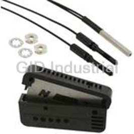
Photoelectric Sensor Thru-beam 1.15m E32A0311M
Photoelectric Sensor Thru-beam 1.15m E32A032M
Photoelectric Sensor Thru-beam 1.15m E32-A034.5M
Photoelectric Sensor Thru-beam 0.46m E32A0412M
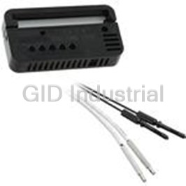
Photoelectric Sensor Thru-beam 0.46m E32-A04-2M
Photoelectric Sensor Thru-beam 0.46m E32A0462M
Request a Quote

The quote request has been received
Close

Facing challenges or have inquiries? Feel free to contact us!
Call Us +1-469-283-2440
What they say about us
FANTASTIC RESOURCE
One of our top priorities is maintaining our business with precision, and we are constantly looking for affiliates that can help us achieve our goal. With the aid of GID Industrial, our obsolete product management has never been more efficient. They have been a great resource to our company, and have quickly become a go-to supplier on our list!
Bucher Emhart Glass
EXCELLENT SERVICE
With our strict fundamentals and high expectations, we were surprised when we came across GID Industrial and their competitive pricing. When we approached them with our issue, they were incredibly confident in being able to provide us with a seamless solution at the best price for us. GID Industrial quickly understood our needs and provided us with excellent service, as well as fully tested product to ensure what we received would be the right fit for our company.
Fuji
HARD TO FIND A BETTER PROVIDER
Our company provides services to aid in the manufacture of technological products, such as semiconductors and flat panel displays, and often searching for distributors of obsolete product we require can waste time and money. Finding GID Industrial proved to be a great asset to our company, with cost effective solutions and superior knowledge on all of their materials, it’d be hard to find a better provider of obsolete or hard to find products.
Applied Materials
CONSISTENTLY DELIVERS QUALITY SOLUTIONS
Over the years, the equipment used in our company becomes discontinued, but they’re still of great use to us and our customers. Once these products are no longer available through the manufacturer, finding a reliable, quick supplier is a necessity, and luckily for us, GID Industrial has provided the most trustworthy, quality solutions to our obsolete component needs.
Nidec Vamco
TERRIFIC RESOURCE
This company has been a terrific help to us (I work for Trican Well Service) in sourcing the Micron Ram Memory we needed for our Siemens computers. Great service! And great pricing! I know when the product is shipping and when it will arrive, all the way through the ordering process.
Trican Well Service
GO TO SOURCE
When I can't find an obsolete part, I first call GID and they'll come up with my parts every time. Great customer service and follow up as well. Scott emails me from time to time to touch base and see if we're having trouble finding something.....which is often with our 25 yr old equipment.
ConAgra Foods