

 Manufacturers
OMRON AUTOMATION E5ER-QT3DW-FLKAC/DC24

Description
Digital Controllers Offers Multiple I/O And Use A 5-Digit
E5ER-QT3DW-FLKAC/DC24
Part Number
E5ER-QT3DW-FLKAC/DC24
Price
Request Quote
Manufacturer
OMRON AUTOMATION
Lead Time
Request Quote
Category
Thermal Management » Misc Products
Specifications
Manufacturer
Omron Automation
Manufacturers Part #
E5ER-QT3DW-FLKAC/DC24
Lead Time
8 Week Lead Time
Sub-Categories
Miscellaneous Tools and Supplies
Factory Pack Quantity
1
Datasheet

Extracted Text
Digital Controllers E5ER CSM_E5ER_DS_E_4_3 E5ER Digital Controllers offer high speed, high precision, and multiple I/O and use a 5-digit, 3-row LCD display for high visual clarity. • A short sampling period of 50 ms enables use in applications requiring high-speed response. • PV, SP, and MV data is displayed simultaneously in a 3-row, negative LCD display with a backlight. • Multipoint control, cascade control, and proportional control are possible with a single Controller. • When using models with CompoWay/F communications, initial settings can be downloaded and settings can be masked using Support Software (CX-Thermo version 4.0 or higher). For the most recent information on models that have been certified for • Equipped with calculation functions as a standard (e.g., square safety standards, refer to your OMRON website. root calculation and broken-line approximation). • DeviceNet Communications Data setting and monitoring can be performed without any Refer to Safety Precautions for All E5@R special programming. Models. Refer to E5AR/E5ER Operation for operating procedures. Model Number Structure Note: When your order, specify the power supply voltage. ■ Model Number Legend 5. Auxiliary outputs E5ER-@@@@@@@@@-@@@ Blank:None 1 23 4 5 67 8 9 10 4: 4PST-NO relay outputs 1. Constant values/Program T: 2 transistor outputs None: Constant values 6. Optional function 1 2. Control method Blank:None Blank: Standard, or heating/cooling control 3: RS-485 communications P: Position-proportional control 7. Optional function 2 3. Output 1 Blank:None R: DPST-NO relay outputs D: 4 event inputs Q: Pulse voltage and pulse voltage/current outputs 8. Input 1 C: Current and current outputs B: Universal-input and 2 event inputs 4. Output 2 F: Universal-input and FB Blank:None W: Universal-input and universal-input R: Relay 9. Input 2 Q: Pulse voltage and pulse voltage/current outputs Blank:None C: Current and current outputs W: Universal-input and universal-input 10.Communications Method Blank:None FLK: CompoWay/F DRT: DeviceNet Note: The above model number legend is intended as a functional description of models. Not all possible combinations of functions are available. Confirm model availability in Ordering Information when ordering. The CX-Thermo Support Software (version 4.0 or higher) can be used to easily set parameters in conversational form. Note: Be sure to read the precautions for correct use and other precautions in the following user's manual before using the Digital Controller. E5AR/E5ER Digital Controller User’s Manual (Cat. No. Z182) E5AR/E5ER Digital Controller DeviceNet Communication User’s Manual (Cat. No. H124) 1 E5ER Ordering Information When your order, specify the power supply voltage. ■ Digital Controllers Standard Controllers (100 to 240 VAC) Size Control type Control mode Outputs (control/ Optional functions Model transfer) Auxiliary Event Serial outputs inputs commu- (SUB) nications 48 × 96 Basic control Single-loop standard control 2 points: Pulse volt- 4 2 No E5ER-Q4B mm (1 loop) Single-loop heating and cooling control age and Pulse volt- age/current 2 points: Current and E5ER-C4B Current 2 points: Pulse volt- RS-485 E5ER-Q43B-FLK age and Pulse volt- age/current 2 points: Current and E5ER-C43B-FLK Current 2 points: Pulse volt- 2 6 E5ER-QT3DB-FLK age and Pulse volt- (See note age/current 1.) 2 points: Current and E5EAR-CT3DB- Current FLK 4 points: Pulse volt- 4 2 E5ER-QC43B-FLK age and Pulse volt- age/current and Current (2 points) 2-loop control 2-loop standard control 2 points: Pulse volt- 2 4 RS-485 E5ER-QT3DW-FLK Single-loop heating and cooling control age and Pulse volt- (See note Single-loop cascade control age/current 1.) Single-loop control with remote SP 2 points: Current and E5ER-CT3DW-FLK Single-loop proportional control Current Position-pro- Single-loop position-proportional control Relay output 2 4No E5ER-PRTDF portional con- (See note 2.) (1 open, 1 closed) (See note 1.) trol Relay output 4 No RS-485 E5ER-PRQ43F-FLK (1 loop) (1 open, 1 closed) and 1 current (trans- fer) output Note 1: The auxiliary outputs are transistor outputs. 2: Can be switched between close control and floating control. Standard Controllers (24 VAC/DC) Size Control type Control mode Outputs (control/ Optional functions Model transfer) Auxiliary Event Serial outputs inputs commu- (SUB) nications 48 × 96 Basic control Single-loop standard control 2 points: Pulse volt- 4 2 No E5ER-Q4B mm (1 loop) Single-loop heating and cooling control age and Pulse volt- age/current 2 points: Current and E5ER-C4B Current 4 points: Pulse volt- 4 2 RS-485 E5ER-QC43B-FLK age and Pulse volt- age/current and Current (2 points) 2-loop control 2-loop standard control 2 points: Pulse volt- 2 4 RS-485 E5ER-QT3DW-FLK Single-loop heating and cooling control age and Pulse volt- (See note Single-loop cascade control age/current 1.) Single-loop control with remote SP 2 points: Current and E5ER-CT3DW-FLK Single-loop proportional control Current Position-pro- Single-loop position-proportional control Relay output 2 4No E5ER-PRTDF portional con- (See note 2.) (1 open, 1 closed) (See note 1.) trol Relay output 4 No RS-485 E5ER-PRQ43F-FLK (1 loop) (1 open, 1 closed) and 1 current (trans- fer) output Note 1: The auxiliary outputs are transistor outputs. 2: Can be switched between close control and floating control. 2 E5ER DeviceNet-compatible Controllers (100 to 240 VAC) Size Control Control mode Outputs (control/ Optional functions Model type transfer) Auxiliary Event DeviceNet outputs inputs communi- (SUB) cations 48 × 96 Basic control Single-loop standard control 2 points: 2 (See 2 Yes E5ER-QTB-DRT mm (1 loop) Single-loop heating and cooling control Pulse voltage note 1.) Pulse voltage/current 2 points: Current and E5ER-CTB-DRT Current 2-loop con- 2-loop standard control 2 points: 2 (See None Yes E5ER-QTW-DRT trol Single-loop heating and cooling control Pulse voltage note 1.) Single-loop cascade control Pulse voltage/current Single-loop standard control with remote 2 points: Current and E5ER-CTW-DRT SP Current Single-loop proportional control Position-pro- Single-loop position-proportional control Relay output 2 (See None Yes E5ER-PRTF-DRT portional (See note 2.) (1 open, 1 closed) note 1.) control (1 loop) Note: 1. The auxiliary outputs are transistor outputs. 2. Can be switched between close control and floating control. DeviceNet-compatible Controllers (24 VAC/DC) Size Control Control mode Outputs (control/ Optional functions Model type transfer) Auxiliary Event DeviceNet outputs inputs communi- (SUB) cations 48 × 96 Basic control Single-loop standard control 2 points: 2 (See 2 Yes E5ER-QTB-DRT mm (1 loop) Single-loop heating and cooling control Pulse voltage note 1.) Pulse voltage/current 2 points: Current and E5ER-CTB-DRT Current 2-loop con- 2-loop standard control 2 points: 2 (See None Yes E5ER-QTW-DRT trol Single-loop heating and cooling control Pulse voltage note 1.) Single-loop cascade control Pulse voltage/current Single-loop standard control with remote 2 points: Current and E5ER-CTW-DRT SP Current Single-loop proportional control Position-pro- Single-loop position-proportional control Relay output 2 (See None Yes E5ER-PRTF-DRT portional (See note 2.) (1 open, 1 closed) note 1.) control (1 loop) Note: 1. The auxiliary outputs are transistor outputs. 2. Can be switched between close control and floating control. Inspection Results ■ Accessories (Order Separately) The Inspection Report can be ordered at the same time as the Digital Controller using the following model number. Terminal Cover (Sold Separately) Inspection Report (Sold Separately) Descriptions Model Terminal Cover for E5ER E53-COV15 Descriptions Model Inspection Report for E5ER E5ER-K Rubber Packing Model Y92S-P5 Note: The Rubber Packing is provided with the Digital Controller. 3 E5ER Specifications ■ Ratings Supply voltage 100 to 240 VAC, 50/60 Hz 24 VAC, 50/60 Hz; 24 VDC Item (See note 1.) Operating voltage range 85% to 110% of rated supply voltage Power consumption 17 VA max. (with maximum load) 11 VA/7 W max. (with maximum load) Sensor input (See note 2.) Thermocouple: K, J, T, E, L, U, N, R, S, B, W Platinum resistance thermometer: Pt100 Current input: 4 to 20 mA DC, 0 to 20 mA DC (including remote SP input) Voltage input: 1 to 5 VDC, 0 to 5 VDC, 0 to 10 VDC (including remote SP input) (Input impedance: 150 Ω for current input, approx. 1 MΩ for voltage input) Control output Voltage (pulse) output 12 VDC, 40 mA max. with short-circuit protection circuit Current output 0 to 20 mA DC, 4 to 20 mA DC; load: 500 Ω max. (including transfer output) (Resolution: Approx. 54,000 for 0 to 20 mA DC; Approx. 43,000 for 4 to 20 mA DC) Relay output Position-proportional control type (open, closed) N.O., 250 VAC, 1 A (including inrush current) Auxiliary output Relay Output N.O., 250 VAC, 1 A (resistive load) Transistor Output Maximum load voltage: 30 VDC; Maximum load current: 50 mA; Residual voltage: 1.5 V max.; Leakage current: 0.4 mA max. Potentiometer input 100 Ω to 2.5 kΩ Event input Contact Input ON: 1 kΩ max.; OFF: 100 kΩ min. No-contact Input ON: Residual voltage of 1.5 V max.; OFF: Leakage current of 0.1 mA max. Short-circuit: Approx. 4 mA Remote SP input Refer to the information on sensor input. Transfer output Refer to the information on control output. Control method 2-PID or ON/OFF control Setting method Digital setting using front panel keys or setting using serial communications Indication method 7-segment digital display and single-lighting indicator Character Height PV: 9.5 mm; SV: 7.2 mm; MV: 7.2 mm Other functions Depends on model. Ambient operating temperature −10 to 55°C (with no icing or condensation) For 3 years of assured use: −10 to 50°C (with no icing or condensation) Ambient operating humidity 25% to 85% Storage temperature −25 to 65°C (with no icing or condensation) Note 1: The supply voltage (i.e., 100 to 240 VAC or 24 VAC/VDC) depends on the model. Be sure to specify the required type when ordering. 2: The Controller is equipped with multiple sensor input. Temperature input or analog input can be selected with the input type setting switch. There is basic insulation between power supply and input terminals, power supply and output terminals, and input and output terminals. 3: Do not use an inverter output as the power supply. (Refer to Safety Precautions for All E5@R Models.) ■ Input Ranges Platinum Resistance Thermometer, Thermocouple, Current, or Voltage Input Input type Platinum Thermocouple Current Voltage Resistance Thermometer Name Pt100 K J T E L U N R S B W [mA] [V] W/Re 5-26 2300.0 2300 1700.0 1700.0 1800.0 1800 1300.0 1300.0 1300 850.0 850.0 850.0 900 800 Temper- 700 500.0 600.0 20 to 20 to 5 to 5 to 10 to ature 600 400.0 400.0 400.0 Range 4 0 1 0 0 400 150.00 (°C) 200 100 100.0 0 0.0 0.0 0.0 0.0 −100 −20.0 −100.0 −20.0 −100.0 −200 −200.0 −150.00 −200.0 −200.0 −200.0 −200.0 Setting 01 23456789 10 11 12 13 14 15 16 17 18 19 Minimum (Depends on scaling and setting unit 0.1°C 0.01°C 0.1°C number of decimal places.) (SP and alarm) TC.PT TC.PT Input type IN1 IN1 Set to TC.PT. TYPE Set to ANALOG. TYPE setting switch ANALOG ANALOG The shaded area indicates the setting status at the time of purchase. 4 E5ER ■ Characteristics Indication accuracy Thermocouple input with cold junction compensation: (±0.1% of PV or ±1°C, whichever is greater) ±1 digit max. (See note 1.) Thermocouple input without cold junction compensation: (±0.1% FS or ±1°C, whichever is smaller) ±1 digit (See note 2.) Analog input: ±0.1% FS ±1 digit max. Platinum resistance thermometer input: (±0.1% of PV or ±0.5°C, whichever is greater) ±1 digit max. Position-proportional potentiometer input: ±5% FS ±1 digit max. Control mode Standard control (heating or cooling control), heating/cooling control, standard control with remote SP (2-input models only), heating/cool- ing control with remote SP (2-input models only), cascade standard control (2-input models only), cascade heating/cooling control (2-input models only), proportional control (2-input models only), position-proportional control (control-valve control models only) Influence of temperature Thermocouple input (R, S, B, W): (±1% of PV or ±10°C, whichever is greater) ±1 digit max. Other thermocouple input: (±1% of PV or ±4°C, whichever is greater) ±1 digit max. Influence of temperature ∗K-type thermocouple at −100°C max.: ±10°C max. Influence of EMS. Platinum resistance thermometer: (±1% of PV or ±2°C, whichever is greater) ±1 digit max. (at EN61326-1) Analog input: (±1%FS) ±1 digit max. Control period 0.2 to 99.0 s (in units of 0.1 s) for time-proportioning control output Proportional band (P) 0.00% to 999.99% FS (in units of 0.01% FS) Integral time (I) 0.0 to 3,999.9 s (in units of 0.1 s) Derivative time (D) 0.0 to 3,999.9 s (in units of 0.1 s) Hysteresis 0.01% to 99.99% FS (in units of 0.01% FS) Manual reset value 0.0% to 100.0% (in units of 0.1% FS) Alarm setting range −19,999 to 99,999 EU (See note 3.) (The decimal point position depends on the input type and the decimal point position setting.) Input sampling period 50 ms Insulation resistance 20 MΩ min. (at 500 VDC) Dielectric strength 2,000 VAC, 50/60 Hz for 1 min (between charged terminals of different polarities) 2 Vibration resistance 10 to 55 Hz, 20 m/s for 10 min each in X, Y, and Z directions 2 Shock resistance 100 m/s , 3 times each in X, Y, and Z directions Inrush current 100 to 240-VAC models: 50 A max. 24 VAC/VDC models: 30 A max. Weight Controller only: Approx. 330 g; Mounting bracket: Approx. 60 g; Terminal cover: Approx. 16 g Degree of protection Front panel: NEMA4X for indoor use (equivalent to IP66); Rear case: IP20; Terminals: IP00 Memory protection Non-volatile memory (number of writes: 100,000) Applicable standards UL61010C-1, CSA C22.2 No. 1010-1 EN61010-1 (IEC61010-1): Pollution degree 2/overvoltage category 2 EMC EMI: EN61326-1 (See note 5.) Radiated Interference Electromagnetic Field Strength: EN55011 Group 1 Class A Noise Terminal Voltage: EN55011 Group 1 Class A EMS: EN61326-1 (See note 5.) ESD Immunity: EN61000-4-2: 4 kV contact discharge (level 2) 8 kV air discharge (level 3) Electromagnetic Immunity: EN61000-4-3: 10 V/m (amplitude-modulated, 80 MHz to 1 GHz, 1.4 GHz to 2 GHz) (level 3) Burst Noise Immunity: EN61000-4-4: 2 kV power line (level 3) 2 kV output line (relay output) (level 4) 1 kV measurement line, I/O signal line (level 4) 1 kV communications line (level 3) Conducted Disturbance Immunity: EN61000-4-6: 3 V (0.15 to 80 MHz) (level 3) Surge Immunity: EN61000-4-5: 1 kV line to line (power line, output line (relay output)) (level 2) 2 kV line to ground (power line, output line (relay output)) (level 3) Power Frequency Magnetic Field Immunity: EN61000-4-8: 30 A/m (50 Hz) continuous field Voltage Dip/Interrupting Immunity: EN61000-4-11: 0.5 cycle, 100% (rated voltage) Note: 1. K-, T-, or N-type thermocouple at −100°C max.: ±2°C ±1 digit max. U- or L-type thermocouple: ±2°C ±1 digit max. B-type thermocouple at 400°C max.: No accuracy specification. R- or S-type thermocouple at 200°C max.: ±3°C ±1 digit max. W-type thermocouple: (±0.3% of PV or ±3°C, whichever is greater) ±1 digit max. 2. U- or L-type thermocouple: ±1°C ±1 digit R- or S-type thermocouple at 200°C max.: ±1.5°C ±1 digit 3. “EU” (Engineering Unit) represents the unit after scaling. If a temperature sensor is used it is either °C or °F. 4. Conditions: Ambient temperature from −10 to 23 to 55°C and voltage of −15% to 10% of rated voltage. 5. Industrial electromagnetic environment (EN/IEC 61326-1 Table 2) 5 E5ER ■ Communications Specifications Transmission path connection Multiple points Communications method RS-485 (two-wire, half duplex) Synchronization method Start-stop synchronization Baud rate 9,600, 19,200, or 384,000 bps Transmission code ASCII Data bit length 7 or 8 bits Stop bit length 1 or 2 bits Error detection Vertical parity (none, even, odd) Block check character (BCC): CompoWay/F CRC-16: Modbus Flow control None Interface RS-485 Retry function None Communications buffer 217 bytes Communications response send wait time 0 to 99 ms, Default: 20 ms DeviceNet Item Specifications Communications protocol Conforms to DeviceNet Communications Remote I/O Master-slave connections (polling, bit-strobe, COS, or cyclic) functions communications Conform to DeviceNet specifications. I/O allocations Can allocate any I/O data from the Configurator. Can allocate any data, such as parameters specific to the Devicenet, and the Digital Controller variable area. Up to 2 blocks for the IN Area, up to a total of 100 words. One block for the OUT Area, up to 100 words (first word is always allocated to Output Enable Bits). Message Explicit message communications communications CompoWay/F communications commands can be sent (commands are sent in explicit mes- sage format). Connection format Combination of multidrop and T-branch connections (for trunk and drop lines) Baud rate DeviceNet: 500, 250, or 125 kbps, or automatic detection of master baud rate Communications media Special 5-wire cable (2 signal lines, 2 power lines, and 1 shield line) Communications distance Baud rate Network length Drop line length Total drop line length 500 kbps 100 m max. (100 m max.) 6 m max. 39 m max. 250 kbps 250 m max. (100 m max.) 6 m max. 78 m max. 125 kbps 500 m max. (100 m max.) 6 m max. 156 m max. The values in parentheses apply when Thin Cables are used. Supply voltage DeviceNet power supply: 24 VDC Allowable voltage range DeviceNet power supply: 11 to 25 VDC Current consumption 50 mA max. (24 VDC) Maximum number of nodes that can be 64 (includes Configurator when used) connected Maximum number of slaves that can be 63 connected Error control CRC error detection Power supply Power supplied from DeviceNet communications connector. 6 E5ER Wiring Terminals ■ E5ER Standard Controller Connections E5ER-Q4B E5ER-C4B E5ER-AB-500 A B E53-ARR4 E5ER-AB-500 A B E53-ARR4 24 VAC/DC 100-240 VAC Auxiliary outputs 24 VAC/DC 100-240 VAC Auxiliary outputs - + 1 - + 1 B (Relay outputs) B (Relay outputs) 2 COM 2 COM 1 1 + - + - 3 SUB1 3 SUB1 2 2 4 4 SUB2 SUB2 3 3 Input power supply Input power supply 5 5 COM COM depends on the model. 4 depends on the model. 4 100 to 240 VAC 100 to 240 VAC 6 SUB3 6 SUB3 5 5 or 24 VAC/DC or 24 VAC/DC (no polarity) (no polarity) 1 SUB4 1 SUB4 6 6 2 2 3 3 4 4 5 5 6 6 C D E C D E E53-ARQC E5ER-AB-500 E53-ARCC E5ER-AB-500 Event inputs Event inputs 1 1 EV1 1 EV1 1 2 EV2 OUT2 2 EV2 2 2 OUT2 + Current output + Voltage output 3 3 COM 4-20 mA DC, 500 Ω max. COM 3 3 12 V 40 mA - + - + 0-20 mA DC, 500 Ω max. 4 4 OUT1 4 (Switching by output 4 Voltage output + - - + - - type setting) 5 5 - 5 - 5 12 V 40 mA or OUT1 - - Current output 6 6 6 Current output 6 ++ ++ 4-20 mA DC, 500 Ω max. 4-20 mA DC, 500 Ω max. C C I V PT TC E I V PT TC E 0-20 mA DC, 500 Ω max. (Current) (Voltage) 0-20 mA DC, 500 Ω max. (Current) (Voltage) (Thermocouple) (Thermocouple) (Switch using output type setting.) (Resistance thermometer) (Resistance thermometer) (Switch using output type setting.) E5ER-Q43B-FLK E5ER-C43B-FLK E53-ARR4 E5ER-AB-500 E53-ARR4 E5ER-AB-500 A B A B 100-240 VAC Auxiliary outputs 100-240 VAC Auxiliary outputs B (Relay outputs) B (Relay outputs) 1 1 COM COM 1 1 2 2 SUB1 SUB1 2 2 3 3 SUB2 SUB2 3 3 4 4 COM COM 4 4 5 5 E53-ARQC3 + SUB3 SUB3 5 5 B(+) 1 6 6 RS-485 SUB4 - SUB4 6 6 A(-) 2 1 1 OUT2 + Voltage output 3 2 2 12 V 40 mA - OUT1 4 3 3 Voltage output + 4 5 4 12 V 40 mA or - Current output 6 5 5 4-20 mA DC, 500 Ω max. C 0-20 mA DC, 500 Ω max. 6 6 (Switch using output type setting.) C D E C D E E5ER-AB-500 E53-ARCC3 E5ER-AB-500 Event inputs + Event inputs B(+) 1 EV1 EV1 1 1 RS-485 - A(-) OUT2 2 EV2 EV2 2 2 Current output + 3 COM 4-20 mA DC, 500 Ω max. COM 3 3 + - + 0-20 mA DC, 500 Ω max. 4 4 4 (Switch using output - + - - - type setting.) 5 - - 5 5 OUT1 - Current output 6 6 ++ 6 ++ 4-20 mA DC, 500 Ω max. C I V PT TC E I V PT TC E 0-20 mA DC, 500 Ω max. (Current) (Voltage) (Current) (Voltage) (Thermocouple) (Thermocouple) (Switch using output type setting.) (Resistance thermocouple) (Resistance thermometer) 7 E5ER E5ER-QT3DB-FLK E5ER-CT3DB-FLK E5ER-AB-500 E53-ARB4 E5ER-AB-500 E53-ARB4 AB AB 100-240 VAC 100-240 VAC B B Event inputs Event inputs 1 1 1 1 2 2 EV3 EV3 2 2 3 3 EV4 EV4 3 3 4 4 EV5 EV5 4 4 5 5 E53-ARQC3 EV6 E53-ARCC3 EV6 5 5 + + B(+) 1 B(+) 1 6 6 COM COM RS-485 6 RS-485 6 - - A(-) A(-) 2 1 2 1 OUT2 OUT2 + + Current output Voltage output 3 2 3 2 4-20 mA DC, 500 Ω max. 12 V 40 mA - - 0-20 mA DC, 500 Ω max. 4 3 4 3 OUT1 (Switch using output Voltage output + + 5 4 type setting.) 5 4 12 V 40 mA or - - OUT1 Current output 6 6 5 5 4-20 mA DC, 500 Ω max. Current output C C 0-20 mA DC, 500 Ω max. 4-20 mA DC, 500 Ω max. 6 6 (Switch using output type setting.) 0-20 mA DC, 500 Ω max. C D E C D E (Switch using output type setting.) E5ER-AB-500 E5ER-AB-500 E53-ART2 E53-ART2 Event inputs Event inputs Auxiliary outputs EV1 Auxiliary outputs EV1 1 1 1 1 (Transistor outputs) (Transistor outputs) EV2 EV2 2 2 2 2 COM COM + 3 + 3 3 3 + + SUB1 SUB1 4 4 - - 4 4 - - - - - - 5 5 + + 5 5 SUB2 SUB2 ++ 6 ++ 6 - - 6 6 D I V PT TC D I V PT TC E E (Current) (Voltage) (Current) (Voltage) D D (Thermocouple) (Thermocouple) (Resistance thermometer) (Resistance thermometer) E5ER-QC43B-FLK E5ER-AB-500 E53-ARR4 AB 24 VAC/DC 100-240 VAC Auxiliary outputs - + B (Relay outputs) 1 COM 1 + - 2 Input power supply depends SUB1 2 on the model. 3 100 to 240 VAC SUB2 3 or 24 VAC/DC (no polarity) 4 COM 4 5 E53-ARQC3 + SUB3 5 B(+) 1 6 RS-485 - SUB4 6 A(-) 2 1 OUT2 + Voltage output 3 2 12 V 40 mA - 4 OUT1 3 Voltage output + 5 4 12 V 40 mA or - Current output 6 5 4-20 mA DC, 500 Ω max. C 0-20 mA DC, 500 Ω max. 6 (Switch using output type setting.) C D E E53-ARCC E5ER-AB-500 Event inputs 1 EV1 1 OUT4 2 EV2 2 Current output + 3 4-20 mA DC, 500 Ω max. COM 3 - + 0-20 mA DC, 500 Ω max. 4 4 (Switch using output + - - type setting.) 5 - 5 OUT3 - 6 Current output 6 ++ 4-20 mA DC, 500 Ω max. D I V PT TC E 0-20 mA DC, 500 Ω max. (Current) (Voltage) (Thermocouple) (Resistance thermometer) (Switch using output type setting.) 8 E5ER E5ER-QT3DW-FLK (2-loop Control) E5ER-CT3DW-FLK (2-loop Control) E5ER-AW-500 E53-ARB4 E5ER-AW-500 E53-ARB4 AB A B 24 VAC/DC 100-240 VAC 24 VAC/DC 100-240 VAC B B - + - + Event inputs Event inputs 1 1 1 1 + - + - 2 2 EV3 EV3 2 2 Input power supply depends Input power supply depends on the model. on the model. 3 3 EV4 EV4 3 3 100 to 240 VAC 100 to 240 VAC or 24 VAC/DC (no polarity) 4 or 24 VAC/DC (no polarity) 4 EV5 4 EV5 4 5 5 E53-ARQC3 EV6 E53-ARCC3 EV6 5 5 + + B(+) 1 B(+) 1 6 6 COM COM RS-485 6 6 RS-485 - - A(-) A(-) 2 2 1 1 OUT2 OUT2 + + Current output 3 2 3 2 Voltage output 4-20 mA DC, 500 Ω max. 12 V 40 mA - - 0-20 mA DC, 500 Ω max. 4 4 3 3 OUT1 (Switch using output Voltage output + + 5 4 type setting.) 5 4 12 V 40 mA or OUT1 - - Current output 6 5 6 5 Current output 4-20 mA DC, 500 Ω max. 4-20 mA DC, 500 Ω max. C C 0-20 mA DC, 500 Ω max. 6 6 0-20 mA DC, 500 Ω max. (Switch using output type setting.) (Switch using output type setting.) C D E C D E E5ER-AW-500 E5ER-AW-500 E53-ART2 E53-ART2 Auxiliary outputs 1 Auxiliary outputs 1 1 - 1 - (Transistor outputs) - (Transistor outputs) - Input 2 Input 2 2 2 2 2 + + + 3 + 3 + I + I V PT TC V PT TC 3 3 SUB1 SUB1 4 4 - - 4 4 - - - - Input 1 Input 1 5 5 + + 5 5 SUB2 6 SUB2 6 + + + + - - 6 6 I V PT TC E I V PT TC E D D (Current) (Voltage) (Current) (Voltage) D (Thermocouple) D (Thermocouple) (Resistance thermometer) (Resistance thermometer) E5ER-PRTDF E5ER-PRQ43F-FLK E53-ARB4 E5ER-PAF-500 AB E53-ARR4 E5ER-PAF-500 Auxiliary outputs 24 VAC/DC 100-240 VAC A B 24 VAC/DC 100-240 VAC B 1 Event inputs - + (Relay outputs) - + B 1 1 2 COM 1 + - + - EV3 2 2 Input power supply depends Input power supply depends 3 SUB1 2 on the model. on the model. EV4 3 3 100 to 240 VAC or 24 VAC/DC 4 SUB2 100 to 240 VAC 3 (no polarity) or 24 VAC/DC (no polarity) 4 EV5 4 5 COM 4 EV6 E53-ARRR3 5 5 6 + SUB3 5 E53-ARRR B(+) COM 1 6 6 RS-485 1 SUB4 - 6 1 A(-) Relay output 2 1 2 250 VAC 1 A Relay output 2 3 2 250 VAC 1 A OUT2 Closed 3 3 4 3 OUT2 Closed 4 4 5 4 OUT1 5 Open 5 6 OUT1 5 Open 6 C 6 6 C D E C C D E E5ER-PAF-500 E53-ARQC O E5ER-PAF-500 Potentiometer E53-ART2 1 1 O Potentiometer W 1 Auxiliary outputs 2 2 1 OUT4 W (Transistor outputs) + C 2 Voltage output 3 3 2 C 12 V 40 mA + - 3 + 4 OUT3 4 + 3 - Voltage output + - SUB1 4 - 5 - 5 - 12 V 40 mA or 4 - - - 5 Current output 6 + 6 + + 5 4-20 mA DC, 500 Ω max. + 6 SUB2 + D I V PT TC E - 0-20 mA DC, 500 Ω max. (Current) (Voltage) 6 (Thermocouple) I V PT TC D E (Switch using output type setting.) (Resistance thermometer) (Current) (Voltage) D (Thermocouple) (Resistance thermometer) 9 - - + + - - + + E5ER ■ E5ER DeviceNet-compatible Controller Connections E5ER-QTB-DRT E5ER-CTB-DRT E5ER-AB-500 E53-ARDRT E5ER-AW-500 E53-ARDRT AB 24 VAC/DC 100-240 VAC A B 24 VAC/DC 100-240 VAC DeviceNet Connector DeviceNet Connector - + - + 1 1 Red (V+) Red (V+) White (CAN H) White (CAN H) + - + - 2 2 − (Shield) Input power supply − (Shield) Input power supply depends on the model. Blue (CAN L) depends on the model. Blue (CAN L) 3 3 100 to 240 VAC 100 to 240 VAC Black (V−) Black (V−) or 24 VAC/DC (no polarity) 4 or 24 VAC/DC (no polarity) 4 5 5 E53-ARQC E53-ARCC 1 1 6 6 2 1 2 1 OUT2 OUT2 + + Current output Voltage output 3 2 3 2 4-20 mA DC, 500 Ω max. 12 V 40 mA - - 0-20 mA DC, 500 Ω max. 4 3 4 3 OUT1 (Switch using output Voltage output + + type setting.) 5 4 5 4 12 V 40 mA or OUT1 - - Current output 6 6 5 Current output 5 4-20 mA DC, 500 Ω max. 4-20 mA DC, 500 Ω max. C C 0-20 mA DC, 500 Ω max. 6 6 0-20 mA DC, 500 Ω max. (Switch using output type setting.) (Switch using output type setting.) C D E C D E E5ER-AB-500 E5ER-AW-500 E53-ART2 E53-ART2 Event inputs 1 Auxiliary outputs EV1 Auxiliary outputs 1 1 - 1 - (Transistor outputs) (Transistor outputs) Input 2 2 EV2 2 2 2 + + 3 COM + 3 + I V PT TC 3 3 + SUB1 SUB1 4 4 - - 4 4 - - - - Input 1 5 - 5 + + 5 5 6 SUB2 SUB2 + + ++ 6 - - 6 6 I V PT TC E D I V PT TC D E (Current) (Voltage) (Thermocouple) (Current) (Voltage) D D (Thermocouple) (Resistance thermometer) (Resistance thermometer) E5ER-QTW-DRT (2-loop Control) E5ER-CTW-DRT (2-loop Control) E5ER-AW-500 E53-ARDRT E5ER-AW-500 E53-ARDRT A B B 24 VAC/DC 100-240 VAC 24 VAC/DC 100-240 VAC A DeviceNet Connector DeviceNet Connector - + - + 1 1 Red (V+) Red (V+) White (CAN H) White (CAN H) + - + - 2 2 Input power supply depends − (Shield) − (Shield) Input power supply depends on the model. Blue (CAN L) on the model. Blue (CAN L) 3 3 100 to 240 VAC Black (V−) 100 to 240 VAC Black (V−) or 24 VAC/DC (no polarity) 4 or 24 VAC/DC (no polarity) 4 5 5 E53-ARQC E53-ARCC 1 1 6 6 2 1 2 1 OUT2 OUT2 + + Current output Voltage output 3 2 3 2 4-20 mA DC, 500 Ω max. 12 V 40 mA - - 0-20 mA DC, 500 Ω max. 4 OUT1 3 4 3 (Switch using output Voltage output + + 5 4 type setting.) 5 4 12 V 40 mA or - OUT1 - Current output 6 5 6 Current output 5 4-20 mA DC, 500 Ω max. 4-20 mA DC, 500 Ω max. C C 0-20 mA DC, 500 Ω max. 6 6 0-20 mA DC, 500 Ω max. (Switch using output type setting.) (Switch using output type setting.) C D E C D E E5ER-AW-500 E5ER-AW-500 E53-ART2 E53-ART2 1 1 Auxiliary outputs Auxiliary outputs 1 - 1 - (Transistor outputs) - - Input 2 (Transistor outputs) Input 2 2 2 2 2 + + + 3 + 3 + I + I V PT TC V PT TC 3 3 SUB1 4 SUB1 4 - - 4 - 4 - - - Input 1 Input 1 5 5 + + 5 5 SUB2 6 6 + + SUB2 + + - - 6 6 I V PT TC E I V PT TC E D D (Current) (Voltage) (Current) (Voltage) (Thermocouple) (Thermocouple) D D (Resistance thermometer) (Resistance thermometer) 10 - - + + - - + + - + - + E5ER E5ER-PRTF-DRT E5ER-PAF-500 E53-ARDRT A B 24 VAC/DC 100-240 VAC DeviceNet Connector - + 1 Red (V+) White (CAN H) + - 2 − (Shield) Input power supply depends on the model. Blue (CAN L) 3 100 to 240 VAC Black (V−) or 24 VAC/DC (no polarity) 4 5 E53-ARRR 6 1 1 Relay output 2 2 250 VAC 1 A 3 3 Closed OUT2 4 4 5 5 OUT1 Open 6 6 C C D E E5ER-PAF-500 E53-ART2 O Potentiometer 1 Auxiliary outputs 1 W (Transistor outputs) 2 2 C 3 + + 3 SUB1 4 - - 4 - - 5 + 5 + 6 SUB2 + - 6 I V PT TC D E (Current) (Voltage) D (Thermocouple) (Resistance thermometer) 11 E5ER Nomenclature E5ER Operation Indicators MS/NS Indicators No. 1 Display Top: MS Bottom: NS No. 2 Display No. 3 Display DeviceNet communications connector Used to connect the DeviceNet communications cables. Mode Key Down Key The DeviceNet communications power is also supplied through this connector. Level Key Up Key The connector included with the DeviceNet-compatible Controllers is the FKC 2.5/5-STF-5.08 AU M (PHOENIX CONTACT). Function Key 1/ Function Key 2/ Auto/Manual Key Channel Key Dimensions Note: All units are in millimeters unless otherwise indicated. E5ER 110 11.5 95 (99)* Terminal cover (E53-COV15; sold separately) 48 3 2 1 2 3 4 5 6 96 111 1 2 3 4 5 6 Crimp terminal size: M3 Mounting Bracket (Accessory) * The value in parentheses are for DeviceNet-compatible Controllers. Panel Cutouts +0.6 45 0 60 min. 120 min. Recommended panel thickness is 1 to 8 mm. Group mounting is not possible. (Maintain the specified mounting space between Controllers.) +0.8 92 0 When tw o or more Controllers are mounted, make sure that the surrounding temperature does not exceed the allowable operating temperature specified in the specifications. 12 E5ER ■ Accessories (Order Separately) Terminal Cover E53-COV15 (for E5ER) 48 95 28.5 10.1 Unit Label Sheet Y92S-L1 11.8 4.8 Rubber Packing Y92S-P5 (for DIN48 × 96) Order the Rubber Packing separately if it becomes lost or damaged. (Refer to page 3.) The Rubber Packing can be used to achieve an IP66 degree of protection. (Deterioration, shrinking, or hardening of the rubber packing may occur depending on the operating environment. Therefore, periodic replacement is recommended to ensure the level of waterproofing specified in NEMA4. The time for periodic replacement depends on the operating environment. Be sure to confirm this point at your site. Consider one year a rough standard. OMRON shall not be liable for the level of water resistance if the customer does not perform periodic replacement.) The Rubber Packing does not need to be attached if a waterproof structure is not required. ALL DIMENSIONS SHOWN ARE IN MILLIMETERS. To convert millimeters into inches, multiply by 0.03937. To convert grams into ounces, multiply by 0.03527. In the interest of product improvement, specifications are subject to change without notice. 13 Terms and Conditions Agreement Read and understand this catalog. Please read and understand this catalog before purchasing the products. Please consult your OMRON representative if you have any questions or comments. Warranties. (a) Exclusive Warranty. Omron’s exclusive warranty is that the Products will be free from defects in materials and workmanship for a period of twelve months from the date of sale by Omron (or such other period expressed in writing by Omron). Omron disclaims all other warranties, express or implied. (b) Limitations. OMRON MAKES NO WARRANTY OR REPRESENTATION, EXPRESS OR IMPLIED, ABOUT NON-INFRINGEMENT, MERCHANTABILITY OR FITNESS FOR A PARTICULAR PURPOSE OF THE PRODUCTS. BUYER ACKNOWLEDGES THAT IT ALONE HAS DETERMINED THAT THE PRODUCTS WILL SUITABLY MEET THE REQUIREMENTS OF THEIR INTENDED USE. Omron further disclaims all warranties and responsibility of any type for claims or expenses based on infringement by the Products or otherwise of any intellectual property right. (c) Buyer Remedy. Omron’s sole obligation hereunder shall be, at Omron’s election, to (i) replace (in the form originally shipped with Buyer responsible for labor charges for removal or replacement thereof) the non-complying Product, (ii) repair the non-complying Product, or (iii) repay or credit Buyer an amount equal to the purchase price of the non-complying Product; provided that in no event shall Omron be responsible for warranty, repair, indemnity or any other claims or expenses regarding the Products unless Omron’s analysis confirms that the Products were properly handled, stored, installed and maintained and not subject to contamination, abuse, misuse or inappropriate modification. Return of any Products by Buyer must be approved in writing by Omron before shipment. Omron Companies shall not be liable for the suitability or unsuitability or the results from the use of Products in combination with any electrical or electronic components, circuits, system assemblies or any other materials or substances or environments. Any advice, recommendations or information given orally or in writing, are not to be construed as an amendment or addition to the above warranty. See http://www.omron.com/global/ or contact your Omron representative for published information. Limitation on Liability; Etc. OMRON COMPANIES SHALL NOT BE LIABLE FOR SPECIAL, INDIRECT, INCIDENTAL, OR CONSEQUENTIAL DAMAGES, LOSS OF PROFITS OR PRODUCTION OR COMMERCIAL LOSS IN ANY WAY CONNECTED WITH THE PRODUCTS, WHETHER SUCH CLAIM IS BASED IN CONTRACT, WARRANTY, NEGLIGENCE OR STRICT LIABILITY. Further, in no event shall liability of Omron Companies exceed the individual price of the Product on which liability is asserted. Suitability of Use. Omron Companies shall not be responsible for conformity with any standards, codes or regulations which apply to the combination of the Product in the Buyer’s application or use of the Product. At Buyer’s request, Omron will provide applicable third party certification documents identifying ratings and limitations of use which apply to the Product. This information by itself is not sufficient for a complete determination of the suitability of the Product in combination with the end product, machine, system, or other application or use. Buyer shall be solely responsible for determining appropriateness of the particular Product with respect to Buyer’s application, product or system. Buyer shall take application responsibility in all cases. NEVER USE THE PRODUCT FOR AN APPLICATION INVOLVING SERIOUS RISK TO LIFE OR PROPERTY OR IN LARGE QUANTITIES WITHOUT ENSURING THAT THE SYSTEM AS A WHOLE HAS BEEN DESIGNED TO ADDRESS THE RISKS, AND THAT THE OMRON PRODUCT(S) IS PROPERLY RATED AND INSTALLED FOR THE INTENDED USE WITHIN THE OVERALL EQUIPMENT OR SYSTEM. Programmable Products. Omron Companies shall not be responsible for the user’s programming of a programmable Product, or any consequence thereof. Performance Data. Data presented in Omron Company websites, catalogs and other materials is provided as a guide for the user in determining suitability and does not constitute a warranty. It may represent the result of Omron’s test conditions, and the user must correlate it to actual application requirements. Actual performance is subject to the Omron’s Warranty and Limitations of Liability. Change in Specifications. Product specifications and accessories may be changed at any time based on improvements and other reasons. It is our practice to change part numbers when published ratings or features are changed, or when significant construction changes are made. However, some specifications of the Product may be changed without any notice. When in doubt, special part numbers may be assigned to fix or establish key specifications for your application. Please consult with your Omron’s representative at any time to confirm actual specifications of purchased Product. Errors and Omissions. Information presented by Omron Companies has been checked and is believed to be accurate; however, no responsibility is assumed for clerical, typographical or proofreading errors or omissions. 2015.8 In the interest of product improvement, specifications are subject to change without notice. OMRON Corporation Industrial Automation Company http://www.ia.omron.com/ (c)Copyright OMRON Corporation 2015 All Right Reserved.
Frequently asked questions
How does Electronics Finder differ from its competitors?

Is there a warranty for the E5ER-QT3DW-FLKAC/DC24?
Which carrier will Electronics Finder use to ship my parts?
Can I buy parts from Electronics Finder if I am outside the USA?
Which payment methods does Electronics Finder accept?
Why buy from GID?

Quality
We are industry veterans who take pride in our work

Protection
Avoid the dangers of risky trading in the gray market

Access
Our network of suppliers is ready and at your disposal

Savings
Maintain legacy systems to prevent costly downtime

Speed
Time is of the essence, and we are respectful of yours
Related Products
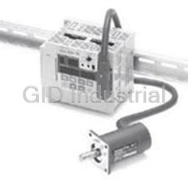
Cam Positioners With High Speed and High Precision Double Machine Productivity 3F88L160
Cam Positioners With High Speed and High Precision Double Machine Productivity 3F88L162
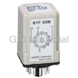
Controllers SURGE SUPRESSOR 61F-03B
Controllers SURGE SUPRESSOR 61F-04B
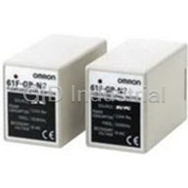
Conductive Level Controller 61F-GP-N2220VAC
Conductive Level Controller 61F-GP-N224VAC
Request a Quote

The quote request has been received
Close

Facing challenges or have inquiries? Feel free to contact us!
Call Us +1-469-283-2440
What they say about us
FANTASTIC RESOURCE
One of our top priorities is maintaining our business with precision, and we are constantly looking for affiliates that can help us achieve our goal. With the aid of GID Industrial, our obsolete product management has never been more efficient. They have been a great resource to our company, and have quickly become a go-to supplier on our list!
Bucher Emhart Glass
EXCELLENT SERVICE
With our strict fundamentals and high expectations, we were surprised when we came across GID Industrial and their competitive pricing. When we approached them with our issue, they were incredibly confident in being able to provide us with a seamless solution at the best price for us. GID Industrial quickly understood our needs and provided us with excellent service, as well as fully tested product to ensure what we received would be the right fit for our company.
Fuji
HARD TO FIND A BETTER PROVIDER
Our company provides services to aid in the manufacture of technological products, such as semiconductors and flat panel displays, and often searching for distributors of obsolete product we require can waste time and money. Finding GID Industrial proved to be a great asset to our company, with cost effective solutions and superior knowledge on all of their materials, it’d be hard to find a better provider of obsolete or hard to find products.
Applied Materials
CONSISTENTLY DELIVERS QUALITY SOLUTIONS
Over the years, the equipment used in our company becomes discontinued, but they’re still of great use to us and our customers. Once these products are no longer available through the manufacturer, finding a reliable, quick supplier is a necessity, and luckily for us, GID Industrial has provided the most trustworthy, quality solutions to our obsolete component needs.
Nidec Vamco
TERRIFIC RESOURCE
This company has been a terrific help to us (I work for Trican Well Service) in sourcing the Micron Ram Memory we needed for our Siemens computers. Great service! And great pricing! I know when the product is shipping and when it will arrive, all the way through the ordering process.
Trican Well Service
GO TO SOURCE
When I can't find an obsolete part, I first call GID and they'll come up with my parts every time. Great customer service and follow up as well. Scott emails me from time to time to touch base and see if we're having trouble finding something.....which is often with our 25 yr old equipment.
ConAgra Foods