

 Manufacturers
OMRON AUTOMATION S8M-CP04

Description
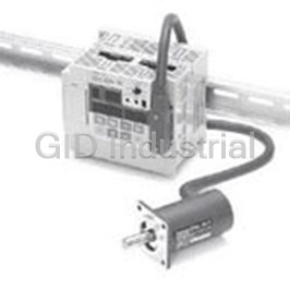
Digital Multicircuit Protector
S8M-CP04
Part Number
S8M-CP04
Price
Request Quote
Manufacturer
OMRON AUTOMATION
Lead Time
Request Quote
Category
Thermal Management » Misc Products
Specifications
Manufacturer
Omron Automation
Manufacturers Part #
S8M-CP04
Lead Time
4 Week Lead Time
Industry Aliases
S8M-CP04
Sub-Categories
Miscellaneous Tools and Supplies
Factory Pack Quantity
1
Datasheet

Extracted Text
Digital Multicircuit Protector S8M CSM_S8M_DS_E_3_1 Complete Flexible DC Circuit Protector That Has a Wide Array of Displays, Alarm Outputs, and Other Digital Functions. • Four circuit protectors in one package Simple setting of current tripping values for each branch outputs in 0.1-A units Startup and shutdown sequence control Display and alarm functions (Input voltage, output current, run time, and over-temperature) Outputs conform to UL Class 2 (at 24 VDC, S8M-CP04-RS only) DIN Rail mounting RoHs-compliant For the most recent information on models that have been certified for Free Support Tool available safety standards, refer to your OMRON website. Refer to Safety Precautions for All Power Supplies and Safety ! Precautions on page 20. Model Number Structure ■ Model Number Legend Note: Not all combinations are possible. Refer to List of Models in Ordering Information, below. S8M-CP04- @@ 12 1. Communications 2. UL Class 2 Output (at 24 VDC) None: Not supported None: Not compliant R: Supported (RS-232) S: Compliant Ordering Information ■ List of Models Note: For details on normal stock models, contact your nearest Recommended Power Supplies OMRON representative. Series name Model number Communications UL Class 2 output Model number S8VS S8VS-06024@ None Not compliant S8M-CP04 S8VS-09024@@ Supported (RS-232C) Not compliant S8M-CP04-R S8VS-12024@@ Compliant S8M-CP04-RS S8VS-18024@@ S8VS-24024@@ S8VM S8VM-05024@@ S8VM-10024@@ S8VM-15024@@ S8VM-30024C S8VM-60024C Note: When selecting the power supply, be sure to include the internal power consumption of the S8M (approx. 10 W) and not just the power consumption of the load. This Datasheet describes only the minimum setting operations required when using the S8M for the first time. Refer to the S8M User's Manual (Cat. No. Z241), when making further settings. 1 S8M Specifications ■ Ratings/Characteristics Item Model S8M-CP04 S8M-CP04-R S8M-CP04-RS Number of branches 4 I/O Rated input voltage 24 VDC (19.2 to 26.4 VDC) character- Allowable input current 17.0 A max. 16.0 A max. istics Maximum tripping output current 4.0 A 3.8 A (per branch output) Internal voltage drop (See note 1.) 0.5 VDC max. (at 4.0 A) 0.7 VDC max. (at 3.8 A) Output leakage current 10 mA max. Power 4 branches output, 10 W max. (at 4.0 A) 15 W max. (at 3.8 A) consump- normal operation tion 4 branches output, 3 W max. (See note 2.) tripping operation Functions Tripping Abnormal voltage 28.8 V (fixed), tripping alarm output tripping Abnormal current Setting range: 0.5 to 4.0 A (in 0.1-A units), tripping alarm Setting range: 0.5 to 3.8 A (in 0.1-A tripping output units), tripping alarm output Tripping alarm out- Transistor output put 30 VDC max., 50 mA max., leakage current: 0.1 mA max., residual voltage: 2 V max. Alarms Overvoltage Setting range: 20.0 to 28.8 V (in 0.1-V units), alarm output Undervoltage Setting range: 18.0 to 26.4 V (in 0.1-V units), alarm output Overcurrent Setting range: 0.5 to 4.0 A (in 0.1-A units), alarm output Setting range: 0.5 to 3.8 A (in 0.1-A units), alarm output Run time Setting range: 0.0 to 99.9 kh (in 0.1-kh units), alarm output (The alarm output is disabled if the time is set to 0.0 kh.) Alarm output Transistor output 30 VDC max., 50 mA max., leakage current: 0.1 mA max., residual voltage: 2 V max. Temperature Temperature Setting range: 25 to 80°C, over-temperature output Over-temperature Transistor output output 30 VDC max., 50 mA max., leakage current: 0.1 mA max., residual voltage: 2 V max. Display Input voltage Display range: 17.0 to 30.0 V Display accuracy: 2% rdg ±1 digit max. Output current Branch output display range: 0.0 to 4.0 A Peak output current display range:0.0 to 10.0 A Total current display range: 0.0 to 40.0 A Display accuracy: 5% FS (4 A) ±1 digit max. Run time Display range: 0.0 to 99.9 kh Display accuracy: 2% rdg ±1 digit max. Temperature Display range: −10 to 100°C Display accuracy: 2°C ±1 digit max. External tripping input 19.2 to 30 VDC, minimum signal width: 10 ms, tripping within 20 ms of input Startup sequence Can be enabled/disabled for each branch output, setting range: 0.0 to 99.9 s in 0.1-s units. Shutdown sequence Can be enabled/disabled for each branch output, setting range: 0.0 to 99.9 s in 0.1-s units. Communications None Supported (RS-232C) Sampling period 1 ms 2 S8M Item Model S8M-CP04 S8M-CP04-R S8M-CP04-RS Other Ambient operating temperature Refer to the derating curve in Engineering Data (with no condensation or icing) Storage temperature −25 to 65°C Ambient operating humidity 25% to 85% (storage humidity: 25% to 90%) Dielectric strength 1.0 kVAC for 1 min (between all charged sections and all non-charged sections; detection cur- rent: 20 mA) 500 VAC for 1 min (between all I/O and I/O signals/communications; detection current: 20 mA) 500 VAC for 1 min (between all I/O signals and communications; detection current: 20 mA) 500 VAC for 1 min (between input signals and all output signals; detection current: 20 mA) Insulation resistance 100 MΩ min. (between all charged sections and all non-charged sections) at 500 VDC 100 MΩ min. (between all I/O and I/O signals/communications) at 500 VDC 100 MΩ min. (between all I/O signals and communications) at 500 VDC 100 MΩ min. (between input signals and all output signals) at 500 VDC Vibration resistance 10 to 55 Hz, 0.375-mm single amplitude for 2 h each in X, Y, and Z directions 2 Shock resistance 150 m/s , 3 times each in ±X, ±Y, and ±Z directions EMI Conducted Conforms to EN 61204-3 Class B Emission Radiated Emission Conforms to EN 61204-3 Class B EMS Conforms to EN 61204-3 High severity levels Approved UL: UL 508 (Listing), UL 60950-1 UL 508 (Listing, Class 2: Per UL standards 1310), UL60950-1 cUL: CSA C22.2 No. 107.1 CSA C22.2 No. 107.1 (Class 2: Per No. 223) cUR: CSA No. 60950-1 CSA No. 60950-1 EN 50178 (= VDE 0160), EN 50178 (= VDE 0160), EN/VDE: EN 60950-1 (= VDE 0805 Teil 1) EN 60950-1 (= VDE 0805 Teil 1) KOSHA S Mark KOSHA S Mark Weight 400 g max. Note: 1. A voltage drop will occur in the S8M. Consider the voltage drop at the output. 2. When selecting the power supply, be sure to include the internal power consumption of the S8M (approx. 10 W) and not just the power consumption of the load. 3 S8M Connections ■ Block Diagrams S8M-CP04-R/-RS only S8M-CP04-RS only Cutoff Current-detection Current-detection Cutoff circuit resistor resistor circuit Thermal Fuse fuse +V +V Voltage Display Temperature DC branch output 1 Switch detection circuit detection Current- −V limiting DC input circuit power supply Power supply Processing Cutoff Cutoff Current-detection Current-detection circuit circuit circuit circuit resistor resistor Thermal Fuse fuse +V DC branch output 2 −V Current- limiting Communi- circuit cations SD Communications terminals RD circuit SG RS-232C Cutoff Current-detection Current-detection Cutoff circuit resistor resistor circuit Thermal Fuse fuse Tripping alarm +V output DC branch output 3 Alarm output −V Current- limiting circuit Over- temperature output Cutoff Current-detection Current-detection Cutoff circuit resistor resistor circuit External Thermal Fuse fuse tripping input +V DC branch output 4 −V Current- limiting circuit −V 4 S8M Construction and Nomenclature ■ Nomenclature No. Name Function 1 Power Input Terminals Connect to the input line. 4 5 6 7 1 (+V), (−V) 2 Branch Output Connect to the load lines. Terminals (+V), (−V) Up to four branch outputs can be connected. 3 Status Indicators Indicate the connection and cutoff (Red, Green) status for each branch output. 14 Cut off: Red, Connected: Green (See 8 note 1.) 4 Tripping Alarm Output Output (transistor: OFF) when the 9 (+, −) error tripping operation functions. 13 10 (See note 2.) 12 11 5 Alarm Output (+, −) Output (transistor: OFF) when a set value for alarm detection is exceeded. 3 (See note 2.) 6 Over-temperature Output (transistor: OFF) when a set Output (+, −) value for over-temperature detection is exceeded. (See note 2.) 7 External Tripping Input The tripping operation can be (+, −) executed with an external input signal. 8 Seven-segment Display Displays measured values and set 2 Note: The S8M-CP04-RS is shown above. (Red) values. 9 Unit Indicators V Lit when the input voltage is being (Orange) displayed. A Lit when the output current is being 4 Tripping alarm output (TRP) displayed. 5 Alarm output (ALM) Flashes when the peak output current is being displayed. 6 Over-temperature output (TMP) kh Lit when the run time is being 7 External tripping input (TRG) displayed. °C Lit when the temperature is being displayed. s Lit when setting the sequence time. 1 to 4 Lit or flashes when displaying branch output information. (See note 3.) 10 Mode Key Used to change the parameter being displayed or to reset the peak hold current value. Internal circuit configuration 11 Up Key Used to move to different setting modes or to increase a set value. 12 Down Key Used to move to different setting modes or to decrease a set value. 13 Reset Key (RST) Used when connecting branch outputs for tripping operation. (See note 4.) 14 Communications Connect to the communications lines Terminals (RD, SD, SG) (RS-232C). (See note 5.) Note: 1. For detailed display methods, refer to Status Indicators on page 13. 2. Configured from independent circuits, and either sinking or sourcing applications are possible. 3. Indicators 1 to 4 will not light except when the current is being displayed. 4. Press for at least 3 s to enable operation. 5. Except for the S8M-CP04. 5 S8M Engineering Data ■ Derating Curve 120 Derating Curve of the S8M S8M-CP04, S8M-CP04-R: Maximum output current 4.0 A S8M-CP04-RS: Maximum output current 3.8 A The ambient temperature that S8M can be 1 100 operating is limited by the maximum output current of one branch terminal on ordinary 80 current condition. 60 40 20 0 −20 −10 0 10203040 50 60 70 Ambient temperature (°C) Note: 1. Internal parts may occasionally be deteriorated or damaged. Do not use the S8M in areas outside the derating curve (i.e., in the area shown by shading A in the above graph). 2. If there is a derating problem, use forced air cooling. ■ Abnormal Current Tripping Standard Detection S8M-CP04/S8M-CP04-R S8M-CP04-RS Time (ms) Time (ms) Tripping characteristics when steady Tripping characteristics when steady Setting Setting range range Current limited by Current limited by Tripping region Tripping region internal circuit internal circuit 100 100 20 20 0.5 4 6 12 0.5 3.8 6 12 Current (A) Current (A) Instantaneous Detection S8M-CP04/S8M-CP04-R S8M-CP04-RS Time (ms) Time (ms) Tripping characteristics when steady Tripping characteristics when steady Setting Setting range range Current limited by Current limited by internal circuit internal circuit Tripping region Tripping region 20 20 0.5 4 12 0.5 3.8 12 Current (A) Current (A) 6 Maximum applied current for any one branch output (%) S8M ■ Mounting Face-up Mounting Standard Mounting Correct Incorrect Note: 1. Improper mounting will interfere with heat dissipation and may occasionally result in deterioration or damage of internal parts. Do not use any mounting method other than the standard one. 2. Take adequate measures to ensure proper heat dissipation to increase the long-term reliability of the S8M. 3. Install the S8M so that the air flow circulates around it, because the S8M is designed to radiate heat by means of natural air flow. Functions ■ Functions Alarm Alarm output Output status Alarm display Abnormal voltage tripping TRP output: OFF All branch outputs cut off. A10 (normally ON) Abnormal current tripping TRP output: OFF Relevant branch output cut A11 (normally ON) off. Overvoltage alarm ALM output: OFF ON A20 (normally ON) Undervoltage alarm ALM output: OFF ON A21 (normally ON) Overcurrent alarm ALM output: OFF ON A22 (normally ON) Run time alarm ALM output: OFF ON A23 (normally ON) Over-temperature output TMP output: OFF ON A30 (normally ON) 7 S8M ■ Tripping Functions Function Operation Abnormal voltage tripping The input voltage is monitored and all branch outputs are cut off if the detection voltage is reached. Notification of the Refer to Chart 1. status is provided using the alarm display and the tripping alarm output (TRP). (See notes 2, 3 and 4.) The alarm display will alternate between the voltage and the alarm code (A10). The primary voltage is measured at the input terminals. Detection voltage: 28.8 V (fixed) Abnormal current tripping The output current is monitored and the branch output that is abnormal is cut off if the preset current is reached. Refer to Chart 2. Notification of the status is provided using the alarm display and the tripping alarm output (TRP). (See notes 2 and 3.) The alarm display will alternate between the current and the alarm code (A11). Abnormal current detection setting range: 0.5 to 4.0 A (S8M-CP04-RS: 0.5 to 0.38 A) in 0.1-A units. Either of two abnormal current tripping types can be set. Standard detection: Tripping within 100 ms. (If a current exceeding the set value flows for 80 ms or more, it is detected as an abnormal current and power is cut off within 20 ms.) Instantaneous detection: Tripping within 20 ms. (If a current exceeding the set value flows for 10 ms or more, it is detected as an abnormal current and power is cut off within 10 ms.) (Refer to page 14 for the setting procedure.) Tripping by external signal The output can be cut off by inputting a voltage to the external tripping input (TRG terminal). If a shutdown sequence (See note 2.) has been set, outputs will be cut off according to the shutdown sequence. (Refer to page 14 for information on the shutdown sequence.) External input signal width: 10 ms min. External tripping enable/disable setting: Enabled Input signal levels High level: 19.2 to 30 VDC Low level: 0 to 2.5 VDC Tripping can also be performed by using communications (S8M-CP04-R/RS only). Refer to the S8M User’s Manual (Cat. No. Z241) for information on tripping using communications. Note: 1. Two abnormal current tripping types are supported depending on the tripping current characteristics: Standard detection and instantaneous detection. Select the required tripping type. 2. Outputs are cut off using semiconductor relays and electrical insulation is not provided. 3. The output will remain OFF and the alarm display and alarm output will not be cleared even if power is restored. The S8M must be reset to restore operation. (Refer to List of Alarms on page 16 for details.) 4. The voltage at the power input terminals is monitored to detect abnormal voltages. To confirm correct output voltages, measure the voltages at the branch output terminals. Chart 1: Operation Timing Chart 2: Operation Timing 28.8 V (Abnormal voltage tripping) (Fixed) (Settable) 4.0 A (Abnormal current tripping) 25 V (Overvoltage alarm) (Settable) 3.5 A (Settable) (Overcurrent alarm) 24 V (Rated) 3.0 A (Normal current) 18 V (Undervoltage alarm) (Settable) 0 0 t t 100 ms 100 ms 20 ms 100 ms (Instantaneous) (Standard) A21 A20 A10 Alarm display A22 A22 A11 Alarm display Alarm output Alarm output (See note.) (See note.) Within 20 ms for instantaneous 20 ms detection and 100 ms for standard detection (depends on tripping type). Tripping alarm output Tripping alarm output (See note.) (See note.) 3 s 3 s Reset Reset Note: The alarm and tripping alarm output are both transistor outputs. Note: The alarm and tripping alarm output are both transistor outputs. It is normally ON and turns OFF when an alarm is detected. It is normally ON and turns OFF when an alarm is detected. 8 S8M ■ Alarm Functions Function Operation Overvoltage alarm The voltage is monitored and notification is provided using the alarm display and output (ALM) if the preset (Refer to Chart 1.) voltage is exceeded for more than 100 ms. The alarm display will alternate between the voltage and the alarm (See notes 1 and 2.) code (A20). The primary voltage is measured at the input terminals. Overvoltage alarm setting range: 20.0 to 28.8 V in 0.1-V units. (Refer to page 14 for the setting procedure.) Overcurrent alarm Each branch output current is monitored and notification is provided using the alarm display and output (ALM) if (Refer to Chart 2.) the preset value is reached. (See note 1.) The alarm display will alternate between the current and the alarm code (A22). Overcurrent alarm setting range: 0.5 to 4.0 A (S8M-CP04-RS: 0.5 to 0.38 A) in 0.1-A units. Either of two tripping types can be set. Standard detection: An alarm is output if the current exceeds the set value for 80 ms or longer. Instantaneous detection: An alarm is output if the current exceeds the set value for 10 ms or longer. (Refer to page 14 for the setting procedure.) Undervoltage alarm The voltage is monitored and notification is provided using the alarm display and output (ALM) if the voltage drops (Refer to Chart 1.) below the preset voltage for more than 80 ms. The alarm display will alternate between the voltage and the alarm (See notes 1 and 2.) code (A21). The primary voltage is measured at the input terminals. Undervoltage alarm setting range: 18.0 to 26.4 V in 0.1-V units. (Refer to page 14 for the setting procedure.) Run time alarm The time that the power is turned ON is calculated as the S8M run time and notification is provided using the (Refer to Chart 3.) alarm display and output (ALM) if the preset time is reached. The alarm display will alternate between the run (See note 1.) time and the alarm code (A23). Display range: 0.0 to 99.9 kh in 0.1-kh units. Run time setting range: 0.0 to 99.9 kh in 0.1-kh units. (Refer to page 14 for the setting procedure.) Over-temperature output The internal temperature of the S8M is monitored using a built-in temperature sensor and notification is provided (Refer to Chart 4.) using the alarm display and over-temperature output (TMP) if the preset temperature is exceeded for more than (See note 1.) 1 s. The alarm display will alternate between the temperature and the alarm code (A30). The over-temperature output is convenient for control operations, such as operating a cooling fan to suppress temperature increased in the control panel. Note: The alarm display and over-temperature output are automatically cleared if the temperature falls below the set temperature. Display range: −10 to 100°C in 1°C units. Temperature setting range: 25 to 80°C in 1°C units. (Refer to page 14 for the setting procedure.) Note: 1. Branch outputs are not cut off for the alarm functions. 2. The voltage at the power input terminals is monitored to detect abnormal voltages. To confirm correct output voltages, measure the voltages at the branch output terminals. Chart 3: Operation Timing Chart 4: Operation Timing Temperature Run time 50.0 kh (Settable) 50°C (Settable) 0 0 t t A30 A30 A30 Power ON Alarm display Over-temperature A23 Alarm display output (See note.) Note: The alarm display and over-temperature output are automatically cleared (with Alarm output hysteresis). (Refer to page 16.) The over-temperature output is a transistor output. (See note.) It is normally ON and turns OFF when an alarm is detected. Run time cleared Note: The alarm output is a transistor output. It is normally ON and turns OFF when an alarm is detected. 9 S8M ■ Other Functions Function Operation Startup sequence The connection timing for branch outputs 1 to 4 can be set individually to offset the connection timing of load (Refer to Chart 5.) devices. Creating time delays between starting loads enables safe load operation. It also reduces total inrush current so that power supply capacity can be optimized. Setting range: 0.0 to 99.0 s in 0.1-s units. (See note.) (Refer to page 14 for the setting procedure.) Shutdown sequence The cutoff timing for branch outputs 1 to 4 can be set individually to offset the cutoff timing of load devices for the (Refer to Chart 6.) external tipping input or to enable an emergency stop. Setting range: 0.0 to 99.0 s in 0.1-s units. (See note.) (Refer to page 14 for the setting procedure.) Startup delay A delay function is provided so that the abnormal current tripping Current Alarm function disabled function or overcurrent alarm function will not be triggered by large for large surge currents initial surge currents, e.g., for capacitive loads or lamp loads. The at startup. abnormal current tripping function will function once the set time has elapsed. (Note: The delay is fixed at 70 ms.) 0 t 70 ms: Delay Note: The sequencing functions are designed for the four branch outputs of one S8M. There is no sync processing between S8M Protectors when more than one S8M is used. Chart 5: Operation Timing Chart 6: Operation Timing Power supply voltage External tripping input Branch output 1 voltage Branch output 1 voltage Startup sequence time Shutdown sequence time Branch output 2 voltage Branch output 2 voltage Startup sequence time Shutdown sequence time Branch output 3 voltage Branch output 3 voltage Startup sequence time Shutdown sequence time Branch output 4 voltage Branch output 4 voltage Startup sequence time Shutdown sequence time Self-diagnosis Within 20 ms (0.5 s min.) Note: Tripping operation is simultaneous for tripping made for abnormal voltages (28.8 V or higher). 10 S8M ■ Key Operations and Displays in Each Mode Power ON When power was When power was turned When power was turned turned OFF in OFF in any mode except ON for the first time Test Mode Test Mode Run Mode Setting Mode Test Mode (See note.) Input Voltage Abnormal Current Value Setting Display Tripping Value Branch Output 1 No key operation for more than 3 s. (See note.) Abnormal Current Output Current Standard/ Connected Cut off Display Tripping Type Instantaneous No key operation for more than 3 s. Peak Output Clearing selected Overcurrent Value Setting Current Display peak output current. Alarm Value Branch Output 2 No key operation for more than 3 s. Or no key operation for more than 3 s. Total Current Overcurrent Standard/ Display Alarm Type Instantaneous Connected Cut off No key operation for more than 3 s. Undervoltage Run Time Display Value Setting Alarm Value No key operation for more than 3 s. Branch Output 3 Temperature Overvoltage Value Setting Display Alarm Value Connected Cut off No key operation for more than 3 s. Run Time Value Setting Alarm Value No key operation for more than 3 s. Branch Output 4 Over-temperature Value Setting Output Value No key operation for more than 3 s. Connected Cut off Startup Sequence Time Setting Time Setting (See note.) No key operation for more than 3 s. Shutdown Sequence Time Setting Cut off all branch outputs Time Setting (See note.) (Shutdown Sequence) No key operation for more than 3 s. Execute External Tripping Input Enable/Disable Setting (See note.) Setting Press for 3 s. Or no key operation for more than 5 s. No key operation for more than 3 s. Communications Settings Connect all branch outputs (Models with Settings communications only) (Startup Sequence) No key operation for more than 3 s. Execute Clearing YES/NO the Run Time Or no key operation for more than 3 s. Mode Selection Press for 3 s. Press for 3 s. Menu Run Mode Setting Mode Test Mode Protection Level Parameter Initialization Press for 3 s. Press for 3 s. Level Selection Yes, initialize. Note: Settings are displayed in order for branch outputs 1 to 4. Specific branch output settings have been omitted. 11 S8M ■ Mode Descriptions ■ Mode Selection Menu The S8M supports a Run Mode, Setting Mode, and Test Mode. The following modes can be selected from the Mode Selection Menu using the Up and Down Keys. Run Mode Used for normal operation. (1) Run Mode Setting Mode Used to set or change S8M parameters. In Run Mode, the current, input voltage, and other values are displayed for the branch outputs. Test Mode Used to test operation for devices connected to the Use this mode for operation once initial settings and system adjustments S8M. have been completed. Note: Refer to the S8M User’s Manual (Cat. No. Z241), when having (2) Setting Mode further setting. Setting Mode is used to set parameters. Operation starts from this mode when using the S8M for the first time. ■ Initial Settings When First Using the S8M (3) Test Mode Test Mode enables forcing branch outputs ON and OFF. Connections and cutoffs can be manipulated for all outputs for each The following diagram illustrates mode transitions for the S8M. When branch output. the S8M is turned ON for the first time, it will enter Setting Mode. First By default, all outputs will be OFF. set the required initial settings for the parameters in Setting Mode Test Mode is thus used to turn ON branch outputs as required. and then switch to Test Mode or Run Mode. (4) Protection Level Protection Level can be used to set restrictions for reading and writing Power ON parameters. Three levels, levels 0, 1, and 2, are available. The default is level 1. Refer to the S8M User's Manual (Cat. No. Z241) for When power was When power the parameters that are protected in each level. turned OFF in any was turned mode except Test Mode Selection Menu OFF in Test Mode Mode Run Mode (5) Parameter Initialization Parameter Initialization is used to return all parameters to their default settings. The Parameter Initialization is not displayed in the default Run Mode run (RUN) protection level (level 1), and the protection level must be set to level 0 to Press for 3 s. initialize parameters. Refer to the S8M User's Manual (Cat. No. Z241) if initialization is required. Setting Mode set (SET) Setting Mode Test Mode tst (TST) Test Mode Press for 3 s. Press for 3 s. Protection Level prt (PRT) Parameter Initialization ini (INI) 12 S8M Status Indicators ■ Run Mode The status indicators light according to the branch output status as Run Mode is used for normal operation. When the input power is described below. turned ON and the mode was Run Mode or Setting Mode the last time the input power was turned OFF, the S8M will start in Run Mode Lit green Normal connection status and connecting the branch outputs will be started. Monitoring of the Flashing green Connection standby status during the startup voltages, currents, run time, and temperature can be confirmed using sequence the Up Key and Down Key ( and ). Lit red Cutoff status for an abnormality (1) Input Voltage Display Flashing red Cutoff status for a redundant protection circuit with The input voltage is monitored and displayed. Class 2 specifications Not lit Forced cutoff or operation stopped 1234 V Akh °C s (2) Output Current Display for Branch Output 1 The output current for a branch output is displayed. 1234 V Akh °C s Status Indicators (3) Peak Output Current Display for Branch Output 1 The peak output current for a branch output is displayed. The output currents and peak output currents for branch outputs 2 to 4 are displayed next. 1234 V Akh °C s (4) Total Current Display The total current for all four branch outputs is Clearing the Peak Output Currents displayed. The peak output currents can be cleared. Select the peak output 1234 V Akh °C s current to be cleared in Run Mode and then use the following operation. (5) Run Time Display The S8M run time is displayed. Peak Output Current Display Waiting display, 1 s 1234 V Akh °C s 1234 V Akh °Cs 1234 V Akh °Cs or (6) Temperature Display 3 s with Clearing completed. The temperature inside the S8M is displayed. no key operations 1234 V Akh s °C 1234 V Akh °Cs 1234 V Akh °Cs Note: 1. The S8M will start in Setting Mode when power is turned ON for the first time after shipping from the factory. After flashing Set value saved (flashes for 3 s) for 3 s 2. Settings cannot be changed in Run Mode. Use Setting Mode to change settings. 3. If a startup sequence has been set, connections will be 1234 V Akh °Cs started according to the set delays. 4. When moving to Run Mode, the branch output ON/OFF Note: Indicator Status Notation status from before entering Run Mode will be maintained. : Lit : Flashing After testing branch output operation in Test Mode, always turn ON the branch outputs before moving to Run Mode. 5. The voltage detection function monitors the voltage at the power input terminals. Measure the voltage at the branch output terminals to confirm that the output voltage is correct. 13 S8M ■ Setting Mode Setting Mode is used to set S8M parameters. Settings can be read or changed while operation continues. The various parameters can be selected as shown below. Abnormal Current Tripping Value The current at which a branch output is cut off. Setting range: 0.5 to 4.0 A (S8M-CP04-RS: 0.5 to C-V External Tripping Input (See note 4.) 3.8 A) The branch output will be cut off if the value Enable/disable the external tripping input set here is exceeded. TRG Abnormal Current Tripping Type (See note 4.) Repeated for each branch output. Detection settings for currents to cut off branch outputs. Standard detection/instantaneous detection C-T Communications Settings (See note 4.) Unit No. Unit number setting (0 to 31) UNO Overcurrent Alarm Value The current at which an alarm is output. Setting range: 0.5 to 4.0 A (S8M-CP04-RS: 0.5 to A-V 3.8 A) An alarm will be output if the value set here is Baud Rate exceeded. Baud rate setting 48: 4,800 bps, 96: 9,600 bps BPS Overcurrent Alarm Type (See note 4.) Detection settings for currents to cut off branch outputs. Standard detection/instantaneous detection A-T Bit Length Repeated for each branch output. Bit length setting (7 or 8) LEN Undervoltage Alarm Value The detection value for a voltage drop at which an alarm is output. V-U Setting range: 18.0 to 26.4 V Stop Bits An alarm will be output if the voltage drops below the value set here. Stop bit setting (1 or 2) BIT Overvoltage Alarm Value The detection value for a voltage rise at which an alarm is output. V-O Setting range: 20.0 to 28.8 V Parity An alarm will be output if the voltage rises above the value set here. Parity setting non: None, evn: Even, odd: Odd PTY Run Time Alarm Value The run time at which an alarm is output. Setting range: 0.0 to 99.9 kh TIM An alarm will be output if the value set here is Send Wait Time exceeded. The alarm will be disabled if the alarm value is set to Send wait time setting 0.0. 0 to 999 ms SWT Over-temperature Output The temperature at which an signal is output. Setting range: 25 to 80°C TMP An over-temperature signal will be output if the value set here is exceeded. Clearing the Run Time (See note 5.) The run time can be cleared. CLR Startup Sequence (See note 4.) Enable/disable the startup sequence and set the time for each branch output. UPS Note: 1. Parameters cannot be changed in protection level 2. Time setting range: 0.0 to 99.9 s 2. The S8M will start in Setting Mode when power is turned ON for the first time after shipping from the factory. Repeated for each branch output. 3. Refer to the S8M User's Manual (Cat. No. Z241), when having further settings. Shutdown Sequence (See note 4.) 4. Not displayed in protection level 1 or 2. Enable/disable the shutdown sequence and set the time 5. Not displayed in protection level 2. for each branch output. DWS Time setting range: 0.0 to 99.9 s Clearing the Run Time Repeated for each branch output. The run time can be cleared. Select the run time to be cleared in Run Mode and then use the following operation. Setting Parameters Waiting display, 1 s Clearing the Run Time Parameters are set as shown below. Example for Setting the Abnormal Current Tripping Value 1234 V Akh °Cs 1234 V Akh °Cs Use and to change the set value. or 3 s with no key operations After no key operations for 1234 V Akh °Cs 1 2 3 4 V Akh °Cs 3 s When finished, press to After flashing save the set value. 1234 V Akh °Cs for 3 s Set value saved (flashes for 3 s). After flashing Set value saved (flashes for 3 s) for 3 s Note: Indicator Status Notation 1234 V Akh °Cs : Lit : Flashing 1234 V Akh °Cs 14 S8M ■ Test Mode ■ Protection Level Setting Device startup operation can be tested by turning ON/OFF branch A protection level can be set to prevent operating errors during outputs either individually or together. The branch outputs that are to normal operation. Reading or changing parameter settings and other be used are set to be connected in Test Mode. The operation to turn operations can be restricted in three levels. all branch outputs ON/OFF together can be used to check startup Protection Intended for Possible operations and shutdown sequences. Level 1. Turning ON/OFF Individual Branch Outputs 0 Facility designers All settings can be read and The following display will appear when Test Mode is entered and the and manufacturers changed. Up and Down Keys ( and ) can be used to select the branch 1 Facility maintenance Some settings can be read and output. Set the branch output number to be output, confirming the personnel changed. number on the mode indicators, and then turn ON the output. The 2 On-site operators Settings can be read but not ON/OFF (connected/cut off) status of the branch outputs can be changed. confirmed on the status indicators. An indicator will light green if the output is connected normally. Select PRT (protection level) from the Mode Selection Menu and Waiting for connection (branch output 1 is OFF) then perform the following procedure. (The following example shows changing to protection level 0.) Setting Protection Level Waiting display, 1 s (operation executed) 1234 V Akh °Cs Changes after the waiting display. Waiting for cutoff (branch output 1 is ON) 1234 V Akh °Cs Mode Selection Menu (Protection Level) Run Mode 1234 V Akh °Cs After no key operations for 2. Turn ON/OFF All Branch Outputs 3 s The Up and Down Keys ( and ) can also be used to select all Set value saved (flashes for 3 s) branch output numbers. The ON or OFF display will appear. Use the Mode Key to execute the operation. The all branch outputs will be connected if the Mode Key ( ) is pressed in this status. Confirm that the status indicators for all branch outputs light green. ■ Parameter Initialization 1234 V Akh °Cs All S8M parameters can be restored to their default settings. Set protection level 0 and then go to the Mode Selection Menu. INI The all branch outputs will be cut off if the Mode Key (parameter initialization) will be added to the menu. Select INI and ( ) is pressed in this status. then perform the following procedure. Confirm that the status indicators for all branch outputs go OFF. Mode Selection Menu 1234 V Akh °Cs Parameter Initialization (Parameter Initialization) Note: Test Mode can be entered only in protection level 0 or 1. It cannot be entered in protection level 2. Note: Indicator Status Notation : Lit : Flashing After no key operations for 3 s Setting Confirmation Run Mode (Flashes for 3 s.) Note: 1. The Mode Selection Menu is not displayed in protection level 1 or 2. The default setting is for protection level 1. 2. Default Settings • The operating mode will change to Setting Mode. The parameters will change to their default settings. All branch outputs will be changed so they are not connected. The protection level will change to level 1. 15 S8M ■ List of Alarms Alarm Name Alarm outputs Power Recovery/reset method display outputs A10 Abnormal voltage TRP output: OFF Cut off Remove the cause of the abnormality and then press the Reset Key ( ) on the front tripping (normally ON) panel for at least 3 s or use communications reset function (S8M-CP04-R/RS only). Power supply will be restarted after recovery. Note: 1. Resetting will be possible from 15 s after the output is cut off. 2. Cutoff and alarm status will not be reset even if the power supply is reset. A11 Abnormal current TRP output: OFF Cut off Remove the cause of the abnormality and then press the Reset Key ( ) on the front tripping (normally ON) panel for at least 3 s or use communications reset function (S8M-CP04-R/RS only). Power supply will be restarted after recovery. Note: 1. Resetting will be possible from 15 s after the output is cut off. 2. Cutoff and alarm status will not be reset even if the power supply is reset. A20 Overvoltage alarm ALM output: OFF ON Remove the cause of the alarm and then press the Reset Key ( ) on the front panel (normally ON) for at least 3 s or use communications reset function (S8M-CP04-R/RS only). Run Mode will be returned to after the alarm is reset. Note: 1. Resetting will be possible if the voltage remains below the set value minus 0.3 V for at least 500 ms from 15 s after the alarm occurs. 2. The alarm status will be reset if the cause of the alarm has been removed when the power supply is reset. A21 Undervoltage ALM output: OFF ON Remove the cause of the alarm and then press the Reset Key ( ) on the front panel alarm (normally ON) for at least 3 s or use communications reset function (S8M-CP04-R/RS only). Run Mode will be returned to after the alarm is reset. Note: 1. Resetting will be possible if the voltage remains above the set value plus 0.3 V for at least 500 ms from 15 s after the alarm occurs. 2. The alarm status will be reset if the cause of the alarm has been removed when the power supply is reset. A22 Overcurrent alarm ALM output: OFF ON Remove the cause of the alarm and then press the Reset Key ( ) on the front panel (normally ON) for at least 3 s or use communications reset function (S8M-CP04-R/RS only). Run Mode will be returned to after the alarm is reset. Note: 1. Resetting will be possible if the current remains below the set value for at least 500 ms from 15 s after the alarm occurs. 2. The alarm status will be reset if the cause of the alarm has been removed when the power supply is reset. A23 Run time alarm ALM output: OFF ON Perform the run time clear operation in Setting Mode. (normally ON) CLR (run time clear) will be displayed on the Setting Mode Menu and YES/NO will be displayed when the Mode Key ( ) is pressed. The run time will be cleared if the Mode Key ( ) is pressed again when Yes is displayed. Note:CLR (run time clear) will not be displayed on the Setting Mode Menu in protection level 2. Change the protection level to level 0 or 1 using the Protection Mode Selection Menu and then clear the run time. A30 Over-temperature TMP output: OFF ON The alarm display and over-temperature output will automatically be reset if the output (normally ON) temperature remains below the set value minus 3°C for at least 5 s. Note: Alarms will be displayed in order of priority if more than one alarm occurs at the same time. Order of priority: A10, A11, A20, A21, A22, A23, A30. 16 S8M ■ Alarm Display ■ Communications The S8M displays alarms according to the parameters set in Setting (S8M-CP04-R/ CP04-RS) Mode. The alarm number and detected value are alternated on the display for each alarm. The built-in RS-232C port can be used to connect special Support Tool to set parameters, monitor, perform tripping operations for Example: Abnormal Current Tripping Alarm at Branch Output 4 branch outputs, and perform other remote monitoring and control 0.5 s operations from a network. Nothing displayed Type RS-232C Communications method Half-duplex 0.5 s 1234 V Akh °C s 1234 V Akh °Cs Sync method Start-stop 0.5 s 0.5 s Baud rate 4,800 or 9,600 bps Current when alarm occurred Transmitted code ASCII Data bit length 7 or 8 bits Note: Indicator Status Notation : Lit : Flashing Stop bit length 1 or 2 bits 1234 V Akh °Cs Error detection Vertical parity and BCC Note: Alarms will be displayed in order of priority if more than one Parity check None, even, or odd alarm occurs at the same time. Protocol CompoWay/F Order of priority: A10, A11, A20, A21, A22, A23, A30. ■ Support Tool ■ Resetting Alarms When an alarm is displayed, remove the cause of the alarm and then (S8M-CP04-R/ CP04-RS) press the Reset Key ( ) for at least 3 s. The following display will The Support Tool is used to set and monitor models that support appear and the alarm will be reset. communications. Parameters can be set, operation can be monitored, and parameter files can be managed. Note: The over-temperature output will automatically be reset when the temperature drops below the set value. All other alarms Support Tool Functions must be reset manually. Reading and writing parameter settings To Run ModeMonitoring present values Run Mode is returned to automatically when the alarm is reset.Monitoring status (cutoff status, normal/error status) Refer to List of Alarms on page 16 for recovery/resetting Applicable OS: Windows 2000 or XP methods. Visit OMRON's website for downloading the Support Tool. 17 S8M Dimensions Note: All units are in millimeters unless otherwise indicated. 75±1 Two, M4 Square Washers Screw 115±1 Eight, M3.5 Square Washers Screw 8.7 89.3 4.1 4.35 94±1 Note: The image is the S8M-CP04-RS Model. 18 S8M ■ DIN Rail (Order Separately) Note: All units are in millimeters unless otherwise indicated. Mounting Rail (Material: Aluminum) PFP-100N 7.3±0.15 PFP-50N 4.5 35±0.3 27±0.15 15 25 25 25 25 15 (5) 1 10 10 (See note.) 1,000 (500) (See note.) Note: Values in parentheses are for the PFP-50N. Mounting Rail (Material: Aluminum) PFP-100N2 16 4.5 35±0.3 27 24 29.2 15 25 25 25 25 15 1 1.5 10 10 1,000 10 End Plate 6.2 1.8 PFP-M M4 × 8 pen-head 1 screw 35.5 50 35.5 1.8 11.5 10 1.3 M4 spring washer 4.8 19 S8M Safety Precautions Refer to Safety Precautions for All Power Supplies. Recommended Wire Types !CAUTION Terminals Wiring materials Torque Strip Minor electric shock, fire, or Product failure may length occasionally occur. Do not disassemble, modify, or repair Power input AWG14 Solid, 1.08 N·m 8 to 10 mm the Product or touch interior of the Product. 2 terminals Stranded (9.6 in. lb.) (2.081 mm ) × 2 Minor burns may occasionally occur. Do not touch the Branch AWG16 to 20 0.8 to 1.0 N·m 6 to 7 mm Product while power is being supplied or immediately output (1.309 to (7.2 to after power is turned OFF. 2 terminals 8.8 in. lb.) 0.517 mm ) Fire may occasionally occur. Tighten terminal screws to Other AWG18 to 26 --- 10 mm the specified torque. terminals (0.823 to 2 Power input terminals: M4 1.08 N·m (9.6 in. lb.) 0.129 mm ) Branch output terminals: M3.5 0.8 to 1.0 N·m Do not apply more than 100-N force to the terminal block when (7.2 to 8.8 in. lb.) tightening screws. Minor electric shock, fire, or Product failure may Be sure to remove the sheet covering the S8M for machining before occasionally occur. Do not allow any pieces of metal or power-ON so that it does not interfere with heat dissipation. conductors or any clippings or cuttings resulting from installation work to enter the Product. Installation Environment The Product will be damaged. Do not incorrectly connect the polarity of power input terminals. Do not use the S8M in locations subject to shocks or vibrations. In particular, install the S8M as far away as possible from contactors or other devices that are vibration sources. Additionally, install a PFP-M End Plate on each end of the S8M. ■ Precautions for Safe Use Install the S8M well away from any sources of strong, high frequency noise and surge. Mounting Operating Life Take adequate measures to ensure proper heat dissipation to increase the long-term reliability of the S8M. Install the S8M so that The life of the S8M is determined by the life of the electrolytic the air flow circulates around it, because the S8M is designed to capacitors used inside. Here, Arrhenius Law applies, i.e., the life will radiate heat by means of natural air flow. be halved for each rise of 10°C or the life will be doubled for each Improper mounting will interfere with heat dissipation and may drop of 10°C. The life of the S8M can thus be increased by reducing occasionally result in deterioration or damage of internal parts. Do its internal temperature. not use any mounting method other than a standard one. Side-by-side mounting of two or more S8M is possible. The switch Ambient Operating and Storage mode power supply connected to inputs and any other sources of heat, however, must be separated as shown below. Environment Store the S8M at a temperature of −25 to 65°C and a humidity of (See note 1.) (See note 2.) 25% to 90%. Internal parts may occasionally be deteriorated or damaged. Do not use the S8M in areas outside the derating curve (i.e., in the area shown by shading ( ) in the derating curve diagram on page 6). Surrounding air temperature for UL 508 Listing and UL60950-1 Recognition is 50°C. Use the S8M at a humidity of 25% to 85%. (See note 3.) (See note 1.) Do not use the S8M in locations subject to direct sunlight. (See note 4.) Do not use the S8M in locations where liquid, foreign matter, or corrosive gases may enter the S8M. Note: 1. Convection of air 2. 75 mm min. 3. 75 mm min. Input Voltage 4. 10 mm min. Input voltage range: 19.2 to 26.4 VDC The S8M provides abnormal voltage protection. All branch outputs Wiring will be cut off if the input voltage exceeds 28.8 VDC. This function, Minor electric shock during operation may occasionally occur. however, does not protect loads and internal parts from high voltages Always attach the terminal cover when using the S8M. in all cases. Be sure the input voltage is within the rated range. Minor fire may possibly occur. Ensure that input and output terminals Outputs may be cut off by the abnormal voltage protection with loads are wired correctly. that generate reverse peak electromotive force. Increases in the temperature of internal parts resulting from heating The S8M operates by DC input. Do not connect AC input to power of wiring materials may result in deterioration or damage to internal input terminals. parts. Use wiring materials suitable to the current being used. The following wiring materials, torque and strip length are recommended to prevent heating and possible fires in wiring materials. 20 S8M Input Power Supply Selection Startup Delay The overcurrent protection characteristics of the power supply The startup delay will not operate when a relay or other device is connected to the input side can cause a voltage drop, resulting in used for ON/OFF control on the output side of the S8M, so a tripping tripping. operation may occasionally occur. If the capacity of the input power supply is too small compared with the load, the overcurrent protection characteristics of the power Connections supply can cause the failure of S8M operating or tripping by voltage It is possible to connect S8M like below. drop occasionally. Select a Power Supply Unit with a current capacity that is 10 to 12 A Correct +V higher than the maximum current supply to the connected devices. −V +V +V +V If the input power supply starts or stops too slowly, the overcurrent −V Power S8M protection characteristics of the power supply can cause the failure of +V supply −V −V −V S8M operating or tripping by voltage drop occasionally. +V −V Tripping Performance +V −V +V +V Always remove the cause of the output first and then reset the alarm −V when abnormal tripping operates. S8M +V −V −V When using a load with a fixed power operation, the S8M may cause +V −V tripping when the power is turned OFF. Internal parts may possibly be deteriorated or damaged. Do not Series connections, such as connecting an S8M to the output of repeatedly perform tripping or recovery operations more than another S8M, are not possible. necessary. Tripping performance depends on the ambient operating Incorrect temperature. Use the S8M within the derating curve shown in the +V derating curve diagram on page 6. −V +V +V V +V −V Power S8M S8M +V Dielectric Strength Test supply −V −V V −V +V The S8M is designed to withstand 500 VAC for 1 minute between I/O −V terminals, all branch output terminals, all output signal terminals, the external tripping input terminals, and all communications terminals of the S8M. The S8M may possibly be damaged from the impulse voltage if a testing device switch is used to abruptly apply or shut off 500 VAC. Increase the applied voltage gradually using the voltage adjustment on the testing device. Always short the specified terminals so that the voltage is applied to all of the terminals at the same time. Power input terminals and branch output terminals are not isolated. Do not perform dielectric strength tests or other insulation appraisal testing between inputs and outputs. External Tripping Input When using the external tripping input, always confirm the application methods described in the S8M User's Manual (Cat. No. Z241) before designing the system. Display The voltage detection function monitors the voltage at the power input terminals. Measure the voltage at the branch output terminals to confirm that the output voltage is correct. Backup Device Connections Observe the following precautions when using a backup device, such as one from OMRON's S8T Series. When connecting a backup device to an S8M branch output, the backup current will be supplied to other branches through internal circuits and it is conceivable that internal parts may be deteriorated or damaged at the same time. When using a backup device with the S8M, connect the backup device to the power input side. When connecting a backup device to the S8M input side, the backup time will be shorter than normal due to internal power consumption. Always confirm the backup time when using a backup device. 21 S8M Troubleshooting If the S8M is not operating properly, check the items listed in the following table before requesting repairs. Stage Observed problem Possible cause Remedy Installation The S8M was installed on a DIN Rail, The S8M's bottom latch is not mounted Check that the S8M has been pressed but the bottom of the Unit is not properly. until the bottom latch clicks. attached. Parameter setting The desired alarm value is not being The setting is not allowed in the present Change the protection level setting. displayed. protection level. The set value was changed, but the The new setting was not saved. After pressing the Up and Down Keys to change wasn't accepted. change the set value, press the Mode Key and verify that the setting flashes and the setting is saved. When the S8M was switched to Run The undervoltage and overvoltage Switch to Setting Mode and check the Mode after setting the overvoltage settings may have been reversed. settings. alarm and undervoltage alarm, the alarm output turned ON and cannot be cleared. Equipment setup The display is flashing “ON” in Test A flashing “ON” display indicates that If the Mode Key is pressed, the output Mode, but power is not being supplied the S8M is waiting to turn ON the will be connected and power will be by the outputs. outputs. supplied.When power is being supplied, “OFF” will flash on the display. The S8M was turned OFF in Test Mode, If the power is turned OFF in Test Either connect all branch outputs in and there was no power from the Mode, all of the branch outputs are cut Test Mode or connect each branch outputs when the S8M was turned ON off for safety reasons. output individually. again. When the output is connected in Test Check whether the status indicator is lit Check for problems such as output Mode, it is cut off immediately and can't red. The current may be higher than the wiring problems.If no problems are be connected again. tripping current. found, press the Reset Key for at least 3 s. Operation The displayed temperature is clearly The S8M detects the Unit's internal When the alarm is being used as a different from the ambient temperature. temperature, which can be 5 to 10°C control signal for a fan or cooling higher than the ambient temperature. equipment, set the alarm value based on the graph in the S8M User’s Manual (Cat. No. Z241). An alarm was output and the cause of The S8M doesn't disregard temporary The alarm can be cleared by pressing the alarm was eliminated, but the alarm errors, so the alarm display is retained the Reset Key for at least 3 s. display cannot be cleared. even after the cause of the alarm is cleared. The peak output current value is not The current may have exceeded the Clear the peak output current value in displayed and the display shows “- - -”. measurable range. Run Mode. The circuit was not designed for a The abnormal current tripping type Either change the abnormal current current that high, but the circuit is cut off (detection method) may be set to tripping type from instantaneous to as soon as power is supplied. “instantaneous.” With instantaneous standard or raise the current tripping detection, an abnormal current is value. detected very quickly and the circuit may be cut off due to excessive current during equipment operation. There may be a large number of Use the S8M's startup sequence devices connected to the output.The function to spread out the connections more devices that are connected, the to the devices (delay the connection of higher the operating current. some devices). Branch output cut off The connection cannot be reset To protect the S8M's internal circuits, at If “RST” is displayed when the Reset immediately after it is cut off. least 15 seconds must pass before a Key is pressed for at least 3 s, the cut- cut-off output can be reset. off output can be reset when 15 s has passed since the output was cut off. The output was reset, but it was The original cause of tripping may not Eliminate the cause of the cutoff and immediately cut off again. have been eliminated. After resetting press the Reset Key for at least 3 s. the error, a large current may have flowed again. Maintenance The run time alarm went OFF, so the The S8M continues adding to the run Clear the run time. equipment was checked and other time. The run time must be reset to 0 in parts were replaced, but the alarm order to clear the alarm. could not be cleared. ALL DIMENSIONS SHOWN ARE IN MILLIMETERS. To convert millimeters into inches, multiply by 0.03937. To convert grams into ounces, multiply by 0.03527. In the interest of product improvement, specifications are subject to change without notice. 22 Terms and Conditions Agreement Read and understand this catalog. Please read and understand this catalog before purchasing the products. Please consult your OMRON representative if you have any questions or comments. Warranties. (a) Exclusive Warranty. Omron’s exclusive warranty is that the Products will be free from defects in materials and workmanship for a period of twelve months from the date of sale by Omron (or such other period expressed in writing by Omron). Omron disclaims all other warranties, express or implied. (b) Limitations. OMRON MAKES NO WARRANTY OR REPRESENTATION, EXPRESS OR IMPLIED, ABOUT NON-INFRINGEMENT, MERCHANTABILITY OR FITNESS FOR A PARTICULAR PURPOSE OF THE PRODUCTS. BUYER ACKNOWLEDGES THAT IT ALONE HAS DETERMINED THAT THE PRODUCTS WILL SUITABLY MEET THE REQUIREMENTS OF THEIR INTENDED USE. Omron further disclaims all warranties and responsibility of any type for claims or expenses based on infringement by the Products or otherwise of any intellectual property right. (c) Buyer Remedy. Omron’s sole obligation hereunder shall be, at Omron’s election, to (i) replace (in the form originally shipped with Buyer responsible for labor charges for removal or replacement thereof) the non-complying Product, (ii) repair the non-complying Product, or (iii) repay or credit Buyer an amount equal to the purchase price of the non-complying Product; provided that in no event shall Omron be responsible for warranty, repair, indemnity or any other claims or expenses regarding the Products unless Omron’s analysis confirms that the Products were properly handled, stored, installed and maintained and not subject to contamination, abuse, misuse or inappropriate modification. Return of any Products by Buyer must be approved in writing by Omron before shipment. Omron Companies shall not be liable for the suitability or unsuitability or the results from the use of Products in combination with any electrical or electronic components, circuits, system assemblies or any other materials or substances or environments. Any advice, recommendations or information given orally or in writing, are not to be construed as an amendment or addition to the above warranty. See http://www.omron.com/global/ or contact your Omron representative for published information. Limitation on Liability; Etc. OMRON COMPANIES SHALL NOT BE LIABLE FOR SPECIAL, INDIRECT, INCIDENTAL, OR CONSEQUENTIAL DAMAGES, LOSS OF PROFITS OR PRODUCTION OR COMMERCIAL LOSS IN ANY WAY CONNECTED WITH THE PRODUCTS, WHETHER SUCH CLAIM IS BASED IN CONTRACT, WARRANTY, NEGLIGENCE OR STRICT LIABILITY. Further, in no event shall liability of Omron Companies exceed the individual price of the Product on which liability is asserted. Suitability of Use. Omron Companies shall not be responsible for conformity with any standards, codes or regulations which apply to the combination of the Product in the Buyer’s application or use of the Product. At Buyer’s request, Omron will provide applicable third party certification documents identifying ratings and limitations of use which apply to the Product. This information by itself is not sufficient for a complete determination of the suitability of the Product in combination with the end product, machine, system, or other application or use. Buyer shall be solely responsible for determining appropriateness of the particular Product with respect to Buyer’s application, product or system. Buyer shall take application responsibility in all cases. NEVER USE THE PRODUCT FOR AN APPLICATION INVOLVING SERIOUS RISK TO LIFE OR PROPERTY OR IN LARGE QUANTITIES WITHOUT ENSURING THAT THE SYSTEM AS A WHOLE HAS BEEN DESIGNED TO ADDRESS THE RISKS, AND THAT THE OMRON PRODUCT(S) IS PROPERLY RATED AND INSTALLED FOR THE INTENDED USE WITHIN THE OVERALL EQUIPMENT OR SYSTEM. Programmable Products. Omron Companies shall not be responsible for the user’s programming of a programmable Product, or any consequence thereof. Performance Data. Data presented in Omron Company websites, catalogs and other materials is provided as a guide for the user in determining suitability and does not constitute a warranty. It may represent the result of Omron’s test conditions, and the user must correlate it to actual application requirements. Actual performance is subject to the Omron’s Warranty and Limitations of Liability. Change in Specifications. Product specifications and accessories may be changed at any time based on improvements and other reasons. It is our practice to change part numbers when published ratings or features are changed, or when significant construction changes are made. However, some specifications of the Product may be changed without any notice. When in doubt, special part numbers may be assigned to fix or establish key specifications for your application. Please consult with your Omron’s representative at any time to confirm actual specifications of purchased Product. Errors and Omissions. Information presented by Omron Companies has been checked and is believed to be accurate; however, no responsibility is assumed for clerical, typographical or proofreading errors or omissions. 2016.6 In the interest of product improvement, specifications are subject to change without notice. OMRON Corporation Industrial Automation Company http://www.ia.omron.com/ (c)Copyright OMRON Corporation 2016 All Right Reserved.
Frequently asked questions
How does Electronics Finder differ from its competitors?

Is there a warranty for the S8M-CP04?
Which carrier will Electronics Finder use to ship my parts?
Can I buy parts from Electronics Finder if I am outside the USA?
Which payment methods does Electronics Finder accept?
Why buy from GID?

Quality
We are industry veterans who take pride in our work

Protection
Avoid the dangers of risky trading in the gray market

Access
Our network of suppliers is ready and at your disposal

Savings
Maintain legacy systems to prevent costly downtime

Speed
Time is of the essence, and we are respectful of yours
Related Products
Cam Positioners With High Speed and High Precision Double Machine Productivity 3F88L160
Cam Positioners With High Speed and High Precision Double Machine Productivity 3F88L162
Controllers SURGE SUPRESSOR 61F-03B
Controllers SURGE SUPRESSOR 61F-04B
Conductive Level Controller 61F-GP-N2220VAC
Conductive Level Controller 61F-GP-N224VAC
Request a Quote

The quote request has been received
Close

Facing challenges or have inquiries? Feel free to contact us!
Call Us +1-469-283-2440
What they say about us
FANTASTIC RESOURCE
One of our top priorities is maintaining our business with precision, and we are constantly looking for affiliates that can help us achieve our goal. With the aid of GID Industrial, our obsolete product management has never been more efficient. They have been a great resource to our company, and have quickly become a go-to supplier on our list!
Bucher Emhart Glass
EXCELLENT SERVICE
With our strict fundamentals and high expectations, we were surprised when we came across GID Industrial and their competitive pricing. When we approached them with our issue, they were incredibly confident in being able to provide us with a seamless solution at the best price for us. GID Industrial quickly understood our needs and provided us with excellent service, as well as fully tested product to ensure what we received would be the right fit for our company.
Fuji
HARD TO FIND A BETTER PROVIDER
Our company provides services to aid in the manufacture of technological products, such as semiconductors and flat panel displays, and often searching for distributors of obsolete product we require can waste time and money. Finding GID Industrial proved to be a great asset to our company, with cost effective solutions and superior knowledge on all of their materials, it’d be hard to find a better provider of obsolete or hard to find products.
Applied Materials
CONSISTENTLY DELIVERS QUALITY SOLUTIONS
Over the years, the equipment used in our company becomes discontinued, but they’re still of great use to us and our customers. Once these products are no longer available through the manufacturer, finding a reliable, quick supplier is a necessity, and luckily for us, GID Industrial has provided the most trustworthy, quality solutions to our obsolete component needs.
Nidec Vamco
TERRIFIC RESOURCE
This company has been a terrific help to us (I work for Trican Well Service) in sourcing the Micron Ram Memory we needed for our Siemens computers. Great service! And great pricing! I know when the product is shipping and when it will arrive, all the way through the ordering process.
Trican Well Service
GO TO SOURCE
When I can't find an obsolete part, I first call GID and they'll come up with my parts every time. Great customer service and follow up as well. Scott emails me from time to time to touch base and see if we're having trouble finding something.....which is often with our 25 yr old equipment.
ConAgra Foods