

 Manufacturers
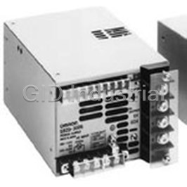
OMRON AUTOMATION S8TS-06024

Description
AC/DC Power Supply Single-OUT 24V 2.5A 60W
S8TS-06024
Part Number
S8TS-06024
Price
Request Quote
Manufacturer
OMRON AUTOMATION
Lead Time
Request Quote
Category
Circuit Protection » AC-DC Power Supply
Specifications
Manufacturer
Omron Automation
Manufacturers Part #
S8TS-06024
Industry Aliases
S8TS-06024
Sub-Categories
AC-DC Power Supplies
Factory Pack Quantity
1
Datasheet

Extracted Text
Switch Mode Power Supply S8TS CSM_S8TS_DS_E_8_1 Block-type Switch Mode Power Supply That Mounts to DIN Rail • One model covers 30 to 120 W (12-V models). One model covers 60 to 240 W (24-V models). Easy creation of multi-power supply configurations with different output power supplies connected together (5-V, 12-V, and 24-V models). Improve power supply system reliability by creating N+1 redun- dant systems (12-V and 24-V models). RoHS-compliant Input conditions: 80 to 370 VDC supported for DC input too (EC Directives and safety standards are not applicable.) For the most recent information on models that have been certified for Operating temperatures to –20°C (24-V models). safety standards, refer to your OMRON website. Refer to Safety Precautions for All Power Supplies and Safety ! Precautions on page 12. Model Number Structure ■ Model Number Legend Note: Not all combinations are possible. Refer to List of Models in Ordering Information, below. S8TS-@@@@@@-@@ 1 2 3 4 1. Capacity 2. Output Voltage 3. Structure 4. Bus Line Connectors 025: 25 W 05: 5 V None: Screw terminals None: Basic Block only 030: 30 W 12: 12 V F: Connector terminals E1: One S8T-BUS01 and one S8T-BUS02 060: 60 W 24: 24 V included as accessories Ordering Information Note: For details on normal stock models, contact your nearest OMRON representative. ■ List of Models Basic Block Output voltage Output current Screw terminal Model Connector terminal Model (See note 3.) With Bus Line Without Bus Line With Bus Line Without Bus Line Connectors Connectors Connectors Connectors (See note 1.) (See note 2.) (See note 1.) (See note 2.) 5 V 5 A --- S8TS-02505 --- S8TS-02505F 12 V 2.5 A S8TS-03012-E1 S8TS-03012 S8TS-03012F-E1 S8TS-03012F 24 V 2.5 A S8TS-06024-E1 S8TS-06024 S8TS-06024F-E1 S8TS-06024F Bus Line Connector Specifications Number of Connectors Model number Connector with DC line connected 1 Connector S8T-BUS01 (For parallel operation) 10 Connectors (See note 4.) S8T-BUS11 Connector with DC line not connected 1 Connector S8T-BUS02 (Not for parallel operation) 10 Connectors (See note 5.) S8T-BUS12 Note: 1. One S8T-BUS01 Connector and one S8T-BUS02 Connector are included as accessories. 2. Bus Line Connectors are ordered separately. When connecting Power Supplies with Bus Line Connectors, order the Bus Line Connectors separately. 3. Attached connectors: 2ESDPLM-05P (for output terminal) and 3ESDPLM-03P (for input terminal) made by DINKLE ENTERPRISE. 4. One package contains 10 S8T-BUS01 Connectors. 5. One package contains 10 S8T-BUS02 Connectors. 1 S8TS Specifications ■ Ratings/Characteristics 12/24-V Models (Basic Block: S8TS-06024@/S8TS-03012@) Item Single operation Parallel operation Efficiency (TYP.) 24-V models: 80% TYP. ; 12-V models: 73% TYP. (with rated input, 100% load) Input Voltage (See note 1.) Ratings: 100 to 240 VAC (Allowable range: 85 to 264 VAC, 80 to 370 VDC (See note 8.)) Frequency (See note 1.) 50/60 Hz (47 to 63 Hz) Current 100 V input 24-V models: 1.0 A max. 24-V models: 1.0 A × (No. of Blocks) max. 12-V models: 0.7 A max. 12-V models: 0.7 A × (No. of Blocks) max. 200 V input 24-V models: 0.5 A max. 24-V models: 0.5 A × (No. of Blocks) max. 12-V models: 0.4 A max. 12-V models: 0.4 A × (No. of Blocks) max. Power factor 24-V models: 0.9 min.; 12-V models: 0.8 min. (with rated input, 100% load) Harmonic current emissions Conforms to EN61000-3-2 Leakage current 100 V input 0.35 mA max. 0.35 mA × (No. of Blocks) max. 240 V input 0.7 mA max. 0.7 mA × (No. of Blocks) max. Inrush current 100 V input 17.5 A max. (for a cold start at 25°C) 17.5 A × (No. of Blocks) max. (for a cold start at 25°C) (See note 5.) 200 V input 35 A max. (for a cold start at 25°C) 35 A × (No. of Blocks) max. (for a cold start at 25°C) Output Voltage adjustment range 24-V models: 22 to 28 V (See note 12-V models: 12 V ±10% (with V.ADJ) (See note 2.) 4.) Ripple 2% (p-p) max. Input variation influence 0.5% max. (with 85 to 264 VAC input, 100% load) Load variation influence 2% max. (with rated input, 10% to 100% load) 3% max. (with rated input, 10% to 100% load) Temperature variation influence 0.05%/°C max. (with rated input and output) Startup time 1,000 ms max. (with 100/200 VAC, rated input) Hold time (See note 5.) 20 ms min. (with 100/200 VAC, rated input) Additional Overload protection (See note 5.) 105% to 140% of rated load current, voltage drop, 100% to 140% of rated load current, voltage drop, au- functions automatic reset tomatic reset Overvoltage protection Yes (See notes 5 and 6.) Parallel operation Yes (Up to 4 Blocks) N+1 redundant system Yes (Up to 5 Blocks) Series operation Yes Undervoltage indicator (See note 5.) Yes (color: red) Undervoltage detection output Yes (open collector output), 30 VDC max., 50 mA max. (See note 5.) Other Ambient operating temperature Refer to the derating curve in Engineering Data (with no icing or condensation). (See note 5.) Storage temperature −25 to 65°C Ambient operating humidity 25% to 85% (Storage humidity: 25% to 90%) Dielectric strength 3.0 kVAC for 1 minute (between all inputs and all outputs; detection current: 20 mA) 2.0 kVAC for 1 minute (between all inputs and PE terminal; detection current: 20 mA) 1.0 kVAC for 1 minute (between all outputs and PE terminal; detection current: 20 mA) Insulation resistance 100 MΩ min. (between all outputs, and all inputs/PE terminal) at 500 VDC Vibration resistance (See note 7.) 10 to 55 Hz, 0.375-mm single amplitude for 2 h each in X, Y, and Z directions 2 Shock resistance (See note 7.) 150 m/s , 3 times each in ±X, ±Y, and ±Z directions Output indicator Yes (color: green) EMI Conducted Emission Conforms to EN61204-3 EN55011 Class B and based on FCC Class A (See note 9.) (See note 8.) Radiated Emission Conforms to EN61204-3 EN55011 Class B (See note 9.) EMS (See note 8.) Conforms to EN61204-3 High severity levels (See note 9.) Approved standards (See note 8.) 24V model UL Listed: UL508 (Listing, Class2 Output: Per UL1310) (See note 3.) UL UR: UL60950-1 (Recognition) cUL Listed: CSA C22.2 No.107.1 (Class2 Output: Per CSA C22.2 No.223) (See note 3.) cUR: CSA C22.2 No.60950-1 EN/VDE: EN50178 (=VDE0160) , EN60950-1 (=VDE0805 Teil1) 12V model UL Listed: UL508 (Listing) UL UR: UL60950-1 (Recognition) cUL Listed: CSA C22.2 No.107.1 cUR: CSA C22.2 No.60950-1 EN/VDE: EN50178 (=VDE0160) , EN60950-1 (=VDE0805 Teil1) Weight 450 g max. 450 g × (No. of Blocks) max. Note: 1. Do not use an inverter output for the Power Supply. Inverters with an output frequency of 50/60 Hz are available, but the rise in the internal temperature of the Power Supply may result in ignition or burning. 2. Refer to page 7 for details on adjusting the output voltage for parallel operation. If set to less than −10%, the undervoltage detection function may operate. Ensure that the output capacity and output current after adjustment do not exceed the rated output capacity and rated output current respectively. Adjusting V.ADV may cause the output voltage to exceed the voltage range. When adjusting the output voltage, confirm the actual output voltage from the Power Supply and be sure that the load is not damaged. 3. Class 2 approval does not apply to parallel operation. 4. The output current is specified at power output terminals. 5. Refer to the Engineering Data on page 8 for details. 6. To reset the protection, turn OFF the input power for one minute or longer and then turn it back again. 7. Be sure to mount End Plates (PFP-M) on both ends of the Power Supply. 8. The range for compliance with EC Directives and safety standards (UL, EN, etc.) is 100 to 240 VAC (85 to 264 VAC). 9. The noise level depends on the wiring method and other factors. Insert one clamp filter (the ZCAT2436-1330A from TDK) as a noise countermeasure on the input line and ground line combined. 2 S8TS 5-V Models (Basic Block: S8TS-02505@) Item Single operation Efficiency (typical) 73% TYP. (with rated input, 100% load) Input Voltage (See note 1.) Ratings: 100 to 240 VAC (Allowable range: 85 to 264 VAC, 80 to 370 VDC (See note 8.)) Frequency (See note 1.) 50/60 Hz (47 to 63 Hz) Current 100 V input 0.7 A max. 200 V input 0.4 A max. Power factor 0.8 min. (with rated input, 100% load) Harmonic current emissions Conforms to EN61000-3-2 Leakage current 100 V input 0.35 mA max. 240 V input 0.7 mA max. Inrush current 100 V input 17.5 A max. (for a cold start at 25°C) (See note 5.) 200 V input 35 A max. (for a cold start at 25°C) Output Voltage adjustment range 5 V ± 10% (with V. ADJ) (See note 2.) (See note Ripple 2% (p-p) max. 3.) Input variation influence 0.5% max. (with 85 to 264 VAC input, 100% load) Temperature variation influence 0.05%/°C max. (with rated input and output) Load variation influence 1.5% max. (with rated input, 10% to 100% load) Startup time (See note 4.) 1,000 ms max. (with 100/200 VAC, rated input) Hold time (See note 4.) 20 ms min. (with 100/200 VAC, rated input) Additional Overload protection (See note 4.) 105% to 140% of rated load current, voltage drop, automatic reset functions Overvoltage protection Yes (See notes 4 and 5.) Parallel operation No N+1 redundant system No Series operation Yes (with the external diode) Undervoltage indicator (See note 4.) Yes (color: red) Undervoltage detection output Yes (open collector output), 30 VDC max., 50 mA max. (See note 4.) Other Ambient operating temperature Refer to the derating curve in Engineering Data. (See note 4.) Storage temperature −25 to 65°C (with no icing or condensation) Ambient operating humidity 25% to 85%, Storage: 25% to 90% Dielectric strength 3.0 kVAC, 50/60 Hz for 1 minute (between all inputs and all outputs; detection current: 20 mA) 2.0 kVAC, 50/60 Hz for 1 minute (between all inputs and PE terminal; detection current: 20 mA) 1.0 kVAC for 1 minute (between all outputs and PE terminal; detection current: 20 mA) Insulation resistance 100 MΩ min. (between all outputs and inputs/PE terminal) at 500 VDC Vibration resistance (See note 6.) 10 to 55 Hz, 0.375-mm single amplitude for 2 h each in X, Y, and Z directions 2 Shock resistance (See note 6.) 150 m/s , 3 times each in ±X, ±Y, and ±Z directions Output indicator Yes (color: green) EMI Conducted Emission Conforms to EN61204-3 EN55011 Class B and based on FCC Class A (See note 7.) Radiated Emission Conforms to EN61204-3 EN55011 Class B EMS (See note 7.) Conforms to EN61204-3 High severity levels Approved standards (See note 7.) UL Listed: UL508 (Listing) UL UR: UL60950-1 (Recognition) cUL Listed: CSA C22.2 No.107.1 cUR: CSA C22.2 No.60950-1 EN/VDE: EN50178 (=VDE0160), EN60950-1 (=VDE0805 Teil1) Weight 450 g max. Note: 1. Do not use an inverter output for the Power Supply. Inverters with an output frequency of 50/60 Hz are available, but the rise in the internal temperature of the Power Supply may result in ignition or burning. 2. If set to less than −10%, the undervoltage detection function may operate. Ensure that the output capacity and output current after adjustment do not exceed the rated output capacity and rated output current respectively. If the output voltage adjuster (V. ADJ) is turned, the voltage will increase by more than 10% of the output voltage, confirm the actual output voltage from the Power Supply and be sure that the load is not damaged. 3. The output current is specified at power output terminals. 4. Refer to the Engineering Data on page 8 for details. 5. To reset the protection, turn OFF the input power for one minute or longer and then turn it back again. 6. Be sure to mount End Plates (PFP-M) on both ends of the Power Supply. 7. The range for compliance with EC Directives and safety standards (UL, EN, etc.) is 100 to 240 VAC (85 to 264 VAC). ■ Reference Value Item Value Definition Reliability (MTBF) 250,000 hrs min. MTBF stands for Mean Time Between Failures, which is calculated according to the probability of acci- dental device failures, and indicates reliability of devices. Therefore, it does not necessarily represent the life of the product. Life expectancy 10 yrs min. The life expectancy indicates average operating hours under the ambient temperature of 40°C and a load rate of 50%. Normally this is determined by the life expectancy of the built-in aluminum electrolytic ca- pacitor. 3 S8TS Connections ■ Block Diagrams S8TS-06024@ and S8TS-03012@ AC (L) +V Fuse Noise INPUT 4.0 A filter DC OUTPUT AC (N) −V Diode for N+1 Inrush Harmonic current Smoothing Rectifier Rectifier and current suppression circuit circuit redundant smoothing protection (Power factor operation circuit circuit improvment) DC LOW OUT Drive control circuit Undervoltage indicator/output Current detection circuit Overcurrent Voltage detection circuit detection circuit Overvoltage detection circuit Photocoupler Connected to Bus Connected to Bus Line Connector Line Connector S8TS-02505@ AC(L) +V Fuse Noise 4.0 A filter INPUT DC OUTPUT AC(N) −V Rectifier Inrush Harmonic current Smoothing Rectifier and current suppression circuit circuit smoothing protection (Power factor circuit circuit improvment) DC LOW OUT Drive control circuit Undervoltage indicator/output Overcurrent Voltage detection circuit detection circuit Overvoltage detection circuit Photocoupler Connected to Bus Connected to Bus Line Connector Line Connector 4 S8TS Construction and Nomenclature ■ Nomenclature Basic Blocks with Screw Terminals Basic Blocks with Connector Terminals (S8TS-@@@@@@) (S8TS-@@@@@@F) 12 3 10 10 1 23 L N L N INPUT INPUT 50/60Hz 50/60Hz AC100 AC100 -240V -240V 1.0A 1.0A L L N N S8TS-06024F POWER SUPPLY S8TS-06024 POWER SUPPLY +V +V -V -V DC ON DC ON Class2 4 Power Class2 Supply Power DC LOW 4 Supply DC LOW 5 V.ADJ OUTPUT 5 DC24V V.ADJ OUTPUT 2.5A 6 DC24V 2.5A -V +V 6 DC LOW -V +V DC LOW 10 7 8 9 7 8 9 10 A AC Input Terminal (L): Connect an input line to this terminal. B AC Input Terminal (N): Connect an input line to this terminal. C Protective Earth (PE) Terminal ( ): Connect a ground line to this terminal. D Output Indicator (DC ON: Green): Lights while DC output is ON. E Undervoltage Indicator (DC LOW: Red): Lights when the voltage at the output terminal drops. F Output Voltage Adjuster (V.ADJ): Use to adjust the output voltage. G Undervoltage Detection Output (DC LOW OUT): Open Collector output H DC Output Terminal (–V): Connect load lines to this terminal. I DC Output Terminal (+V): Connect load lines to this terminal. J Slider: Slide to the lock side when connecting. Unlock the slider when disconnecting. Connector with DC Line Connected Connector with DC Line Not Connected S8T-BUS01 Bus Line Connector S8T-BUS02 Bus Line Connector 1 1 2 2 7 8 8 3 3 4 5 6 A AC Input Terminal (L) B AC Input Terminal (N) C Protective Earth (PE) Terminal ( ) D Parallel Operation Signal Terminal E DC Output Terminal (+V) F DC Output Terminal (−V) G Selector H Connection Status Indicator 5 S8TS Operation ■ Application Methods Increasing Output Capacity Example for 24-V Models Block Power Supply Block Power Supply Output Capacity 60 W 120 W 180 W 240 W Number 1 block 2 blocks 3 blocks 4 blocks of Bus Line Blocks Connector S8T-BUS01 Configuring Multiple Outputs AC input L L L N N N BUS01 BUS02 BUS02 +V -V 12 V 5 V 24 V 24 V S8T-BUS01 S8T-BUS02 S8T-BUS02 30 W 25 W 60 W 60 W 24 V 12 V 5 V 120 W 30 W 25 W Using Parallel Operation Maximum Number of Blocks That Can Use the S8T-BUS01 (DC line connected). (See Figure 1.) Be Linked The S8T-BUS01 Bus Line Connector is equipped with a selector to Basic Blocks can be linked using Bus Line Connectors. prevent erroneous connection of Blocks with different output voltage specifications. Slide the selector to the output voltage for parallel Increasing Output Capacity operation. Models Number of Blocks N+1 Redundant System S8TS-02505@ No No S8TS-03012@ Up to 4 Blocks Up to 5 Blocks S8TS-06024@ Up to 4 Blocks Up to 5 Blocks 24V Selector 12V N+1 Redundant Systems To ensure stable operation when there is a failure in one of the Blocks, use within the derating curve for N+1 redundant systems. Note: Parallel operation is enabled by using a current balance Multi-output Power Supply function. For the current balance function to operate, the S8T- Up to 4 Basic Blocks with different output voltage specifications can BUS01 must be used. be linked. Not Using Parallel Operation Selecting Bus Line Connectors Use the S8T-BUS02 (DC line not connected). (See Figure 2.) Select Bus Line Connectors according to the linking method as S8T-BUS01 S8T-BUS02 follows: LL NN PE PE LL NN PE PE AC Line DC Line −V+V −V+V −V+V −V+V Figure 1: Figure 2: DC line connected DC line not connected (parallel connection) (isolated connection) 6 S8TS Mounting and Removing Bus Line Series Operation ± Output Connectors 24/12-V models 5-V models 24/12-V models 5-V models Pay attention to the following points to maintain electrical L N L N L L N N characteristics. Do not insert/remove the Connectors more than 20 times. Do not touch the Connector terminals. To remove the Connectors, insert a flat-bladed screwdriver S8T S8T alternately at both ends. -BUS02 -BUS02 Load Load Load Load Load Load Adjusting Output Voltage for Parallel Operation The Blocks are factory-set to the rated output voltage. When adjusting output voltages, set the same values for Blocks with output voltage adjuster (V.ADJ) before linking them together. Adjust the set Wiring Linked Blocks values within the limits given in the following table. When linking Blocks together, wire input lines to one Basic Block Model number Difference between output voltages only, otherwise inputs may be shorted internally resulting in damage to the Block. S8TS-03012@ 0.12 V max. Do not wire inputs to more than one S8TS-06024@ 0.24 V max. Do not adjust output voltages after Blocks are linked together. The Incorrect L N L N output voltage may become unstable. Inrush Current The inrush current per Basic Block is 17.5 A max. at 100 VAC and −V+V 35 A max. at 200 VAC. When N Blocks are linked together, the inrush Do not cross-wire Blocks or wire between a Block and another current will be equal to N times that for 1 Basic Block. Be sure to use device. If the current exceeds the rated current, Bus Line Connectors a fuse with the appropriate fusing characteristics or a breaker with may be damaged. the appropriate tripping characteristics. Do not use cross-wire Blocks. Leakage Current Incorrect L N L N L N The leakage current per Basic Block is 0.35 mA max. at 100 VAC and 0.7 mA max. at 240 VAC. When N Blocks are linked together, the leakage current will be equal to N times that for 1 Basic Block. Mounting When Basic Blocks are linked together, it is necessary to wire the PE Mounting Direction terminal of only one Basic Block, not all the Blocks. Standard mounting Yes Series Operation and ± Output Face-up mounting No Other mounting methods No Using 2 Basic Blocks enables series operation and the use of ± output. An external diode is not required for S8TS-06024@ and Use standard mounting only. Using any other mounting method will S8TS-03012@ models, but is required for S8TS-02505@ models. prevent proper hear dissipation and may result in deterioration or Use the following as a rough guide for selecting the diode. damage of internal parts. Type Schottky barrier diode Incorrect Correct Withstand voltage (V ) At least twice the rated output voltage RRM Current with normal direction (I ) At least twice the rated output current F Note: Series operation is possible with different specifications, but the current that flows to the load must not exceed the rated output current of any Block. Standard mounting Face-up mounting 7 S8TS Engineering Data ■ Derating Curves Parallel Operation and Side-by-side Single Operation with Spaces N+1 Redundant System Mounting between Blocks 20 mm min. 5/12-V Models 5/12-V Models 5/12-V Models 120 120 120 200 V input (side-by-side mounting) 200 V input 100 100 100 80 80 80 60 60 60 100/200-V input 100 V input 40 40 40 (parallel operation), DC input 100-V input (side-by-side mounting) 20 20 20 DC input 0 0 0 −20 −10 0 10 20 30 40 50 55 60 70 −20 −10 0 10 20 30 40 50 60 70 −20 −10 0 10 20 30 40 50 60 70 Ambient temperature (°C) Ambient temperature (°C) Ambient temperature (°C) 24-V Models 24-V Models 24-V Models 120 120 120 200 V input (side-by-side mounting) 200 V input 100 100 100 80 80 80 60 60 60 100 V input 100/200-V input 40 40 40 (parallel operation), DC input 100-V input (side-by-side mounting) 20 20 20 DC input 0 0 0 −30 −20 −10 0 102030405060 70 −30 −20 −10 0 102030405060 70 −30 −20 −10 0 102030405060 70 Ambient temperature (°C) Ambient temperature (°C) Ambient temperature (°C) Note: 1. If there is a derating problem, use forced air-cooling. 2. The ambient temperature is specified for a point 50 mm below the Power Supply. 3. Use the rated output for single operation multiplied by N as a reference for the load ratio for an N+1 redundant system. 4. DC Input: If the input voltage is less than 100 VDC, reduce the load to 0.8 or less times the values given in the above derating curves. 8 Load ratio (%) Load ratio (%) Load ratio (%) Load ratio (%) Load ratio (%) Load ratio (%) S8TS ■ Overload Protection ■ Inrush Current, Startup Time, The Power Supply is provided with an overload protection function Hold Time that protects the Power Supply from possible damage by overcurrent. When the output current rises above 105% min. of the rated current Input ON Input OFF (100% min. of the rated current for parallel operation), the protection function is triggered, automatically decreasing the output voltage. AC input When the output current falls within the rated range, the overload voltage protection function is automatically cleared. Inrush current on input application AC input current 90% 96.5% Output voltage Startup time Hold time (20 ms min.) (1,000 ms max.) 0 50 100 Output current (%) ■ Undervoltage Indicator and The values shown in the above diagram are for reference only. Undervoltage Detection Output Note: Internal parts may occasionally deteriorate or damaged if a short-circuited or overcurrent continues for 20 min. or longer. When a drop in the output voltage is detected, the red indicator (DC LOW) lights and transistor (DC LOW: OUT) output turns ON to provide external notification of the error. The detection voltage is set ■ Overvoltage Protection to approximately 80% (75% to 90%) of the rated output voltage. An overvoltage protection function is provided so that excessive Status of indicator Voltage status Output voltage is not applied to the load, e.g., if the feedback circuit in the status (See note 2.) Power Supply fails. When a voltage that is approximately 120% of the rated voltage or more is output, the output voltage is shut OFF. Reset Approx. 80% ON Green lit: ODC ON the input power by turning it OFF for at least 1 minute and then min. of the rated turning it back ON again. Red not lit: DC LOW output voltage Approx. 80% OFF Green lit: DC ON 12-V and 5-V Models (See max. of the rated note 3.) output voltage Red lit: DC LOW Close to 0 V OFF Green not lit: DC ON Overvoltage Red not lit: DC LOW protection operating Note: 1. This function monitors the voltage at the power output terminals. For accurate confirmation of the output status, +10% measure the voltage at the output terminal. Rated output Variable range voltage 2. Transistor output: Open collector –10% 30 VDC max., 50 mA max. ON residual voltage: 2 V max. OFF leakage current: 0.1 mA max. 0 V 3. The indicators become dimmer as the output voltage approaches 0 V. 24-V Models Undervoltage Detection Output Blocks with Screw Terminals Blocks with Connector Terminals Overvoltage protection DC LOW OUT DC LOW OUT operating −V +V 28 V −V +V Rated output voltage Variable range 22 V 0 V The values shown in the above diagrams are for reference only. Note: Do not turn ON the input power again until the cause of the overvoltage has been removed. 9 Output voltage (V) Output voltage (V) Output voltage (V) S8TS Dimensions Note: All units are in millimeters unless otherwise indicted. S8TS-@@@@@ Slider 10 2.5 Six, M4 Square Washers Screw 120±1 100 120±1 80.7 35 5.6 M4 Square Washers Screw (Sliding: 15 max.) 43±1 Rail Stopper 5 S8TS-@@@@@F Slider 7.62 2.5 120±1 120±1 80.7 35 5.6 (Sliding: 15 max.) 5.08 Rail Stopper 43±1 5 ■ DIN Rails (Order Separately) Mounting Rails (Material: Aluminum) 7.3±0.15 PFP-100N PFP-50N 4.5 35±0.3 27±0.15 15 25 10 25 25 10 25 15(5)* 1 1000(500)* *Values in parentheses are for the PFP-50N. 16 PFP-100N2 4.5 35±0.3 29.2 27 24 15 25 10 25 25 10 25 15 1 1.5 1000 End Plate 10 PFP-M 6.2 1.8 Eight, M4 pan-head 1 screw 35.5 50 35.5 1.8 11.5 10 1.3 M4 spring washer 4.8 10 116 116 S8TS Application Examples Machines with various Equipment and systems Standardization Power Supplies with models or equipment with that use multiple power Multiple Outputs Semiconductor various power supply supplies or multiple manufacturing equipment Packing machines specifications power supply outputs Automobile Large control panels manufacturers Electrical appliance Conveyors manufacturers Simplified designing and Simplified creation of design changes. power supplies with Reduced stock and multiple outputs. reduced purchasing funds. Equipment and systems requiring higher reliability in the power supply N+1 Redundant Systems Semiconductor utilities N+1 Redundancy S8TS Operation In an N+1 redundant system, N No special settings are required for N+1 redundant operation Power Supplies of the same with the S8TS. Just link Basic Blocks for redundant operation model are linked in parallel in parallel to enable N+1 redundant operation. connections and one additional A current balance function is used for S8TS N+1 redundant Power Supply of the same operation so that each Block provides the same current. If one model is added for redundancy. Power Supply fails, the remaining Power Supplies share the (N is 1 for a single operation load of the failed Power Supply, and operation continues with system.) This setup increases each Power Supply providing more current. Process equipment system reliability. The Power Supply that has failed can be identified by the output indicator, undervoltage indicator, and undervoltage detection output to enable replacing the Block with a normal Block. Always turn OFF the input power before replacing a Block. To increase Power Supply reliability, use only 90% or less of the maximum rated capacity for N Power Supplies even when N+1 Power Supplies are linked. Output capacity when one Power Output capacity during Process-control systems Supply is down normal operation 11 Output capacity per Power Supply S8TS Safety Precautions Refer to Safety Precautions for All Power Supplies. Wiring !CAUTION Ground the product completely. Failure to do so could cause the Do not disassemble the product or touch internal parts electric shock or malfunction. during power-on. Electric shock may be caused. Ensure that input and output terminals are wired correctly. Use the following material to the wire to be applied to the product for Do not touch the product during power-on, and preventing from the occurrence of the smoking or ignition caused by immediately after poweroff. Hot surface may cause the abnormal load. heat injury. Recommended Wire Type:(For Single unit operation) Electrical shock or minor injury may occasionally occur. Do not touch the terminals while power is being Do not apply more than 100-N force to the terminal block when supplied. Also, always attach the Terminal Cover after tightening it. you complete wiring. Use the following material for the wires to be connected to the S8TS While power is supplied, voltages up to 370 V are to prevent smoking or ignition caused by abnormal loads. generated internally. The voltage can remain for 30 seconds after the power supply is turned OFF. Recommended Wire Size for Single-unit Do not remove any connector cover unless using bus Operation line connectors. Electric shock may be caused. Model Recommended wire size Tighten the terminal screws with torque: 9.6 in-lb S8TS-02505 AWG 14 to 18 (cross-sectional area: 0.823 (1.08N·m), and tighten the connector screw and screw 2 to 2.081 mm ) flange with torque: 2.7 in-lb (0.3N·m). Loose screws S8TS-03012 AWG 14 to 18 (cross-sectional area: 0.823 may cause fire. 2 S8TS-06024 to 2.081 mm ) Minor injury, fire, or device failure may occasionally S8TS-02505F AWG 12 to 18 (cross-sectional area: 0.823 occur. Do not allow any pieces of metal, conductors, or 2 to 3.309 mm ) cuttings from installation work to enter the Power Supply. S8TS-03012F AWG 12 to 20 (cross-sectional area: 0.517 2 S8TS-06024F to 3.309 mm ) ■ Precautions for Safe Use Recommended Wire Size for Parallel Operation Mounting Model Recommended wire size Heat dissipation capacity may be decreased if a non-standard mounting S8TS-03012 For 2 Units con- AWG 14 to 18 (cross-sectional ar- method is used, occasionally resulting in damage to internal components. 2 S8TS-06024 nected in parallel ) ea: 0.823 to 2.081 mm Use only the standard mounting method. For 3 Units con- AWG 14 to 16 (cross-sectional ar- To improve the long-term reliability of devices, give due consideration 2 nected in parallel ea: 1.309 to 2.081 mm ) to heat dissipation when mounting. With the S8TS, heat is dissipated by natural convection. Mount Blocks in a way that allows convection For 4 Units con- AWG 14 (cross-sectional area: 2 in the atmosphere around them. nected in parallel 2.081 mm ) Do not allow cuttings to enter the Power Supply during installation S8TS-03012F For 2 Units con- AWG 12 to 18 (cross-sectional ar- 2 work. S8TS-06024F nected in parallel ea: 0.823 to 3.309 mm ) Be sure to remove the sheet covering the Power Supply for For 3 Units con- AWG 12 to 16 (cross-sectional ar- 2 machining before turning ON the power so that it does not interfere nected in parallel ea: 1.309 to 3.309 mm ) with heat dissipation. For 4 Units con- AWG 12 to 14 (cross-sectional ar- 2 nected in parallel ea: 2.081 to 3.309 mm ) *2 *1 *1 Blocks with Connector Terminals When using Blocks with connector terminals, the current for 1 terminal must not exceed 7.5 A. If a higher current is required, use 2 terminals. *1 *1 *3 Do not insert/remove AC input connectors or DC output connector more than 20 times. *4 *1. Convection of air Installation Environment *2. 75 mm min. *3. 75 mm min. Do not use the Power Supply in locations subject to shocks or vibrations. In particular, install the Power Supply as far as possible *4. 10 mm min. from contactors or other devices that are a vibration source. Be sure When cutting out holes for mounting, make sure that cuttings do not to mount End Plates (PFP-M) on both ends of the Power Supply. enter the interior of the products. Install the Power Supply well away from any sources of strong, high- frequency noise and surge. 12 S8TS Ambient Operating and Storage DIN Rail Mounting Environments To mount the Block on a DIN Rail, hook portion (A) of the Block onto the Rail and press the Block in direction (B). Do not use or store the Power Supply in the following locations. Doing so may result in failure, malfunction, or deterioration of performance characteristics. (A) Do not use the Power Supply in locations subject to direct sunlight. Do not use the Power Supply in locations where the ambient temperature exceeds the range of the derating curve. Do not use the Power Supply in locations where the humidity is (B) outside the range 25% to 85%, or locations subject to condensation To dismount the Block, pull down portion (C) with a flat-blade due to sudden temperature changes. screwdriver and pull out the Block. Do not store the Power Supply in locations where the ambient temperature is outside the range –25 to 65°C or where the humidity is outside the range 25% to 95%. Do not use the Power Supply in locations where liquids, foreign matter, corrosive gases, or corrosive gases may enter the interior of the Power Supply. Short-circuits or overcurrent conditions that last for 20 seconds or longer may cause deterioration or damage to internal parts. 30 mm min. (C) Output Voltage Adjuster (V.ADJ) Rail stopper Do not exert excessive force on the output voltage adjuster (V.ADJ). In Case There Is No Output Voltage Doing so may break the adjuster. Setting the output voltage adjuster (V.ADJ) to 90% or less of the If there is no output voltage, it is possible that overload protection or rated output voltage may cause the undervoltage detection function overvoltage protection is operating. It is also possible that the latch to operate. protection circuit is operating due to the application of a large surge, such as lightning surge. Confirm the 2 points below. If there is still no output voltage, consult your OMRON representative. Bus Line Connectors Checking for Overload Protection: Do not apply strong shocks (e.g., by dropping) to the Bus Line Separate the load line and confirm that it is not in an overload state Connectors. Doing so may result in damage. (including short-circuits). Checking for Overvoltage Protection or Latch Protection: Turn the input power OFF, and then turn it ON again after 1 minute or more has elapsed. Buzzing Noise When the Input Is Turned ON A harmonic current suppression circuit is built into the input power. This circuit can create noise when the input is turned ON, but it will last only until the internal operation stabilizes and does not indicate any problem in the Power Supply. ALL DIMENSIONS SHOWN ARE IN MILLIMETERS. To convert millimeters into inches, multiply by 0.03937. To convert grams into ounces, multiply by 0.03527. In the interest of product improvement, specifications are subject to change without notice. 13 Terms and Conditions Agreement Read and understand this catalog. Please read and understand this catalog before purchasing the products. Please consult your OMRON representative if you have any questions or comments. Warranties. (a) Exclusive Warranty. Omron’s exclusive warranty is that the Products will be free from defects in materials and workmanship for a period of twelve months from the date of sale by Omron (or such other period expressed in writing by Omron). Omron disclaims all other warranties, express or implied. (b) Limitations. OMRON MAKES NO WARRANTY OR REPRESENTATION, EXPRESS OR IMPLIED, ABOUT NON-INFRINGEMENT, MERCHANTABILITY OR FITNESS FOR A PARTICULAR PURPOSE OF THE PRODUCTS. BUYER ACKNOWLEDGES THAT IT ALONE HAS DETERMINED THAT THE PRODUCTS WILL SUITABLY MEET THE REQUIREMENTS OF THEIR INTENDED USE. Omron further disclaims all warranties and responsibility of any type for claims or expenses based on infringement by the Products or otherwise of any intellectual property right. (c) Buyer Remedy. Omron’s sole obligation hereunder shall be, at Omron’s election, to (i) replace (in the form originally shipped with Buyer responsible for labor charges for removal or replacement thereof) the non-complying Product, (ii) repair the non-complying Product, or (iii) repay or credit Buyer an amount equal to the purchase price of the non-complying Product; provided that in no event shall Omron be responsible for warranty, repair, indemnity or any other claims or expenses regarding the Products unless Omron’s analysis confirms that the Products were properly handled, stored, installed and maintained and not subject to contamination, abuse, misuse or inappropriate modification. Return of any Products by Buyer must be approved in writing by Omron before shipment. Omron Companies shall not be liable for the suitability or unsuitability or the results from the use of Products in combination with any electrical or electronic components, circuits, system assemblies or any other materials or substances or environments. Any advice, recommendations or information given orally or in writing, are not to be construed as an amendment or addition to the above warranty. See http://www.omron.com/global/ or contact your Omron representative for published information. Limitation on Liability; Etc. OMRON COMPANIES SHALL NOT BE LIABLE FOR SPECIAL, INDIRECT, INCIDENTAL, OR CONSEQUENTIAL DAMAGES, LOSS OF PROFITS OR PRODUCTION OR COMMERCIAL LOSS IN ANY WAY CONNECTED WITH THE PRODUCTS, WHETHER SUCH CLAIM IS BASED IN CONTRACT, WARRANTY, NEGLIGENCE OR STRICT LIABILITY. Further, in no event shall liability of Omron Companies exceed the individual price of the Product on which liability is asserted. Suitability of Use. Omron Companies shall not be responsible for conformity with any standards, codes or regulations which apply to the combination of the Product in the Buyer’s application or use of the Product. At Buyer’s request, Omron will provide applicable third party certification documents identifying ratings and limitations of use which apply to the Product. This information by itself is not sufficient for a complete determination of the suitability of the Product in combination with the end product, machine, system, or other application or use. Buyer shall be solely responsible for determining appropriateness of the particular Product with respect to Buyer’s application, product or system. Buyer shall take application responsibility in all cases. NEVER USE THE PRODUCT FOR AN APPLICATION INVOLVING SERIOUS RISK TO LIFE OR PROPERTY OR IN LARGE QUANTITIES WITHOUT ENSURING THAT THE SYSTEM AS A WHOLE HAS BEEN DESIGNED TO ADDRESS THE RISKS, AND THAT THE OMRON PRODUCT(S) IS PROPERLY RATED AND INSTALLED FOR THE INTENDED USE WITHIN THE OVERALL EQUIPMENT OR SYSTEM. Programmable Products. Omron Companies shall not be responsible for the user’s programming of a programmable Product, or any consequence thereof. Performance Data. Data presented in Omron Company websites, catalogs and other materials is provided as a guide for the user in determining suitability and does not constitute a warranty. It may represent the result of Omron’s test conditions, and the user must correlate it to actual application requirements. Actual performance is subject to the Omron’s Warranty and Limitations of Liability. Change in Specifications. Product specifications and accessories may be changed at any time based on improvements and other reasons. It is our practice to change part numbers when published ratings or features are changed, or when significant construction changes are made. However, some specifications of the Product may be changed without any notice. When in doubt, special part numbers may be assigned to fix or establish key specifications for your application. Please consult with your Omron’s representative at any time to confirm actual specifications of purchased Product. Errors and Omissions. Information presented by Omron Companies has been checked and is believed to be accurate; however, no responsibility is assumed for clerical, typographical or proofreading errors or omissions. 2016.6 In the interest of product improvement, specifications are subject to change without notice. OMRON Corporation Industrial Automation Company http://www.ia.omron.com/ (c)Copyright OMRON Corporation 2016 All Right Reserved.
Frequently asked questions
How does Electronics Finder differ from its competitors?

Is there a warranty for the S8TS-06024?
Which carrier will Electronics Finder use to ship my parts?
Can I buy parts from Electronics Finder if I am outside the USA?
Which payment methods does Electronics Finder accept?
Why buy from GID?

Quality
We are industry veterans who take pride in our work

Protection
Avoid the dangers of risky trading in the gray market

Access
Our network of suppliers is ready and at your disposal

Savings
Maintain legacy systems to prevent costly downtime

Speed
Time is of the essence, and we are respectful of yours
Related Products
AC/DC Power Supply Single-OUT 12V 27A 300W Medical 12-Pin S82D-3012
AC/DC Power Supply Single-OUT 12V 1.2A 15W S82H-3112
AC/DC Power Supply Single-OUT 24V 2.3A 50W Medical S82H-3524
AC/DC Power Supply Single-OUT 12V 1A 10W 5-Pin S82J01012D
AC/DC Power Supply Single-OUT 24V 0.5A 10W 5-Pin S82J-01024A
AC/DC Power Supply Single-OUT 5V 5A 25W S82J-0205
Request a Quote

The quote request has been received
Close

Facing challenges or have inquiries? Feel free to contact us!
Call Us +1-469-283-2440
What they say about us
FANTASTIC RESOURCE
One of our top priorities is maintaining our business with precision, and we are constantly looking for affiliates that can help us achieve our goal. With the aid of GID Industrial, our obsolete product management has never been more efficient. They have been a great resource to our company, and have quickly become a go-to supplier on our list!
Bucher Emhart Glass
EXCELLENT SERVICE
With our strict fundamentals and high expectations, we were surprised when we came across GID Industrial and their competitive pricing. When we approached them with our issue, they were incredibly confident in being able to provide us with a seamless solution at the best price for us. GID Industrial quickly understood our needs and provided us with excellent service, as well as fully tested product to ensure what we received would be the right fit for our company.
Fuji
HARD TO FIND A BETTER PROVIDER
Our company provides services to aid in the manufacture of technological products, such as semiconductors and flat panel displays, and often searching for distributors of obsolete product we require can waste time and money. Finding GID Industrial proved to be a great asset to our company, with cost effective solutions and superior knowledge on all of their materials, it’d be hard to find a better provider of obsolete or hard to find products.
Applied Materials
CONSISTENTLY DELIVERS QUALITY SOLUTIONS
Over the years, the equipment used in our company becomes discontinued, but they’re still of great use to us and our customers. Once these products are no longer available through the manufacturer, finding a reliable, quick supplier is a necessity, and luckily for us, GID Industrial has provided the most trustworthy, quality solutions to our obsolete component needs.
Nidec Vamco
TERRIFIC RESOURCE
This company has been a terrific help to us (I work for Trican Well Service) in sourcing the Micron Ram Memory we needed for our Siemens computers. Great service! And great pricing! I know when the product is shipping and when it will arrive, all the way through the ordering process.
Trican Well Service
GO TO SOURCE
When I can't find an obsolete part, I first call GID and they'll come up with my parts every time. Great customer service and follow up as well. Scott emails me from time to time to touch base and see if we're having trouble finding something.....which is often with our 25 yr old equipment.
ConAgra Foods