

 Manufacturers
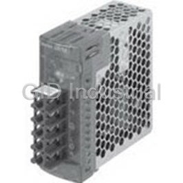
OMRON AUTOMATION S8VM01524AD
Description
AC/DC Power Supply Single-OUT 24V 0.65A 15W 5-Pin
S8VM01524AD
Part Number
S8VM01524AD
Price
Request Quote
Manufacturer
OMRON AUTOMATION
Lead Time
Request Quote
Category
Circuit Protection » AC-DC Power Supply
Specifications
Manufacturer
Omron Automation
Manufacturers Part #
S8VM01524AD
Industry Aliases
S8VM-01524AD
Sub-Categories
AC-DC Power Supplies
Factory Pack Quantity
1
Datasheet

Extracted Text
Switch Mode Power Supply (15/30/50/100/150/300/600/1,500-W Models) S8VM CSM_S8VM_DS_E_12_1 Power Supply Featuring OMRON’s Unique, New Undervoltage Alarm Function with Compact Body Contributing to Machine Downsizing • New undervoltage alarm function assists in determining causes of errors (S8VM-@@@24A@/P@ only). Power failure alarm function provides notification of out put voltage errors (300-, 600-, and 1,500-W models only). Broad range of possibilities with 8 capacities and 29 models to choose from. RoHS-compliant New, attentive design prevents screws from falling out of term inal block (except for output terminals of 300-, 600-, and 1,500-W models). Finger protection prevents electric shock. DIN Rail mounting. Safety standards: UL508/60950-1/1604, CSA C22.2 No. 14/No. 60950-1/No. 213, EN50178, EN60950-1 (The 300-, 600-, and 1,500-W models will not conform to safety standards if the customer replaces the fan.) Conforms to SEMI F47-0200 (when 200-V input is used). Harmonic current emissions: Conforms to EN61000-3-2 (except for 15- and 30-W models). ! Refer to Safety Precautions for All Power Supplies and Safety Precautions on page 32. Model Number Structure ■ Model Number Legend Note: Not all combinations are possible. Refer to List of Models in Ordering Information on page 2. S8VM- @@@@@@@ 3 12 4 1. Power Ratings 3. Configuration/Functions 015: 15 W None: Open-frame type Standard type 030: 30 W C: Covered type Standard type 050: 50 W A: Covered type Undervoltage alarm type (Sinking (emitter COM)) 100: 100 W (See note 2.) 150: 150 W P: Covered type Undervoltage alarm type 300: 300 W (Sourcing (collector COM)) 600: 600 W (See note 2.) 152: 1,500 W 4. Configuration 2. Output Voltage None: Bottom mounting type (See note 3.) 05: 5 V D: DIN Rail mounting bracket type 12: 12 V 15: 15 V 24: 24 V Note: 1. A forced-air cooling method with a fan is used with 300-, 600-, and 1,500-W models. 2. The housing and terminal of the connector for the undervoltage alarm output are provided with the S8VM-05024A@/P@, S8VM- 10024A@/P@ and S8VM-15024A@/P@. 3. Bottom mounting models cannot be used for front mounting. For a front mounting configuration, use a DIN Rail Mounting Bracket model or Mounting Brackets (sold separately). 1 S8VM Ordering Information ■ List of Models Note: For details on normal stock models, contact your nearest OMRON representative. Configura- Power Input voltage Output voltage Output current Bottom mounting DIN Rail mounting bracket tion ratings Standard Undervoltage alarm model Standard Undervoltage alarm model model model Sinking Sourcing Sinking Sourcing Open-frame 15 W 100 to 240 VAC 5 V 3 A S8VM-01505 --- --- S8VM-01505D --- --- type 12 V 1.3 A S8VM-01512 --- --- S8VM-01512D --- --- 15 V 1 A S8VM-01515 --- --- S8VM-01515D --- --- 24 V 0.65 A S8VM-01524 --- --- S8VM-01524D --- --- 30 W 5 V 6 A S8VM-03005 --- --- S8VM-03005D --- --- 12 V 2.5 A S8VM-03012 --- --- S8VM-03012D --- --- 15 V 2 A S8VM-03015 --- --- S8VM-03015D --- --- 24 V 1.3 A S8VM-03024 --- --- S8VM-03024D --- --- 50 W 5 V 10 A S8VM-05005 --- --- S8VM-05005D --- --- 12 V 4.3 A S8VM-05012 --- --- S8VM-05012D --- --- 15 V 3.5 A S8VM-05015 --- --- S8VM-05015D --- --- 24 V 2.2 A S8VM-05024 --- --- S8VM-05024D --- --- 100 W 5 V 20 A S8VM-10005 --- --- S8VM-10005D --- --- 12 V 8.5 A S8VM-10012 --- --- S8VM-10012D --- --- 15 V 7 A S8VM-10015 --- --- S8VM-10015D --- --- 24 V 4.5 A S8VM-10024 --- --- S8VM-10024D --- --- 150 W 5 V 27 A S8VM-15005 --- --- S8VM-15005D --- --- (See note 2.) (See note 2.) 12 V 12.5 A S8VM-15012 --- --- S8VM-15012D --- --- 15 V 10 A S8VM-15015 --- --- S8VM-15015D --- --- 24 V 6.5 A (See note 6.) S8VM-15024 --- --- S8VM-15024D --- --- Covered 15 W 100 to 240 VAC 5 V 3 A S8VM-01505C --- --- S8VM-01505CD --- --- type 12 V 1.3 A S8VM-01512C --- --- S8VM-01512CD --- --- 15 V 1 A S8VM-01515C --- --- S8VM-01515CD --- --- 24 V 0.65 A S8VM-01524C S8VM-01524A (See note 1.) S8VM-01524CD S8VM-01524AD (See note 1.) 30 W 5 V 6 A S8VM-03005C --- --- S8VM-03005CD --- --- 12 V 2.5 A S8VM-03012C --- --- S8VM-03012CD --- --- 15 V 2 A S8VM-03015C --- --- S8VM-03015CD --- --- 24 V 1.3 A S8VM-03024C S8VM-03024A (See note 1.) S8VM-03024CD S8VM-03024AD (See note 1.) 50 W 5 V 10 A S8VM-05005C --- --- S8VM-05005CD --- --- 12 V 4.3 A S8VM-05012C --- --- S8VM-05012CD --- --- 15 V 3.5 A S8VM-05015C --- --- S8VM-05015CD --- --- 24 V 2.2 A S8VM-05024C S8VM-05024A S8VM-05024P S8VM-05024CD S8VM-05024AD S8VM-05024PD 100 W 5 V 20 A S8VM-10005C --- --- S8VM-10005CD --- --- 12 V 8.5 A S8VM-10012C --- --- S8VM-10012CD --- --- 15 V 7 A S8VM-10015C --- --- S8VM-10015CD --- --- 24 V 4.5 A S8VM-10024C S8VM-10024A S8VM-10024P S8VM-10024CD S8VM-10024AD S8VM-10024PD 150 W 5 V 27 A S8VM-15005C --- --- S8VM-15005CD --- --- (See note 2.) (See note 2.) 12 V 12.5 A S8VM-15012C --- --- S8VM-15012CD --- --- 15 V 10 A S8VM-15015C --- --- S8VM-15015CD --- --- 24 V 6.5 A (See note 6.) S8VM-15024C S8VM-15024A S8VM-15024P S8VM-15024CD S8VM-15024AD S8VM-15024PD 300 W 5 V 60 A S8VM-30005C --- --- --- --- --- (See note 12 V 27 A S8VM-30012C --- --- --- --- --- 4.) 15 V 22 A S8VM-30015C --- --- --- --- --- 24 V 14 A S8VM-30024C --- --- --- --- --- Peak current: 16.5 A (200 VAC) 600 W 5 V 120 A S8VM-60005C --- --- --- --- --- (See note 12 V 53 A S8VM-60012C --- --- --- --- --- 4.) 15 V 43 A S8VM-60015C --- --- --- --- --- 24 V 27 A S8VM-60024C --- --- --- --- --- Peak current: 31 A (200 VAC) 1,500 W 24 V 65 A (100 VAC) S8VM-15224C --- --- --- --- --- (See note 70 A (200 VAC) (See note 3.) 4.) Peak current: 105 A (200 VAC) Note: 1. No outputs are built into these models. 2. The output capacity of the S8VM-15005@@ is 135 W. 3. M8 bolts and nuts for the output terminals are not included with the S8VM-15224C. 4. The 300-, 600-, and 1,500-W models use a forced cooling method with built-in fans. 5. To perform front mounting using the bottom mounting models, use the Mounting Brackets (S82Y-VM@@F, sold separately). 6. The output current for UL1604 certification is 6.3 A. 2 S8VM Specifications ■ Ratings/Characteristics Item Power rating 15 W 30 W 50 W 100 W 150 W Efficiency 5-V models 75% min. 75% min. 80% min. 81% min. 81% min. 12-V models 78% min. 79% min. 79% min. 81% min. 81% min. 15-V models 78% min. 79% min. 79% min. 81% min. 81% min. 24-V models 80% min. 81% min. 80% min. 82% min. 83% min. Input Voltage (See note 1.) 100 to 240 VAC (85 to 264 VAC) Frequency (See note 1.) 50/60 Hz (47 to 63 Hz) Current 100-V input 0.5 A max. 0.9 A max. 0.8 A max. 1.4 A max. 2.0 A max. 200-V input 0.25 A max. 0.45 A max. 0.4 A max. 0.7 A max. 1.0 A max. Power factor 100-V input --- 0.98 min. 200-V input --- 0.94 min. Harmonic current emissions --- Conforms to EN 61000-3-2 Leakage 100-V input 0.4 mA max. (at rated output) current 200-V input 0.75 mA max. (at rated output) Inrush current 100-V input 17.5 A max. (for cold start at 25°C) (See note 2.) 200-V input 35 A max. (for cold start at 25°C) Output Voltage adjustment range (See note 3.) −20% to 20% (with V. ADJ) (S8VM-@@@24A@/P@: −10% to 20%) Ripple 3.2% (p-p) max. (5 V), 3.2% (p-p) max. (5 V), 1.5% (p-p) max. (12 V), 1.5% (p-p) max. (12 V), 1.2% (p-p) max. (15 V), 1.2% (p-p) max. (15 V), 1.0% (p-p) max. (24 V), 0.75% (p-p) max. (24 V), (at rated input/output voltage) (at rated input/output voltage) Input variation influence 0.4% max. (at 85 to 264 VAC input, 100%) Load variation influence (rated input 0.8% max. (with rated input, 0 to 100% load) voltage) Temperature variation influence 0.02%/°C max. Startup time (See note 2.) 1,100 ms max. (at rated input/output voltage) 800 ms max. (at rated input/output voltage) Hold time (See note 2.) 20 ms typ. (15 ms min.) (at rated input/output voltage) Additional Overload protection (See note 2.) 105% to 160% of rated load current, voltage 105% to 160% of rated load current, functions drop, intermittent, automatic reset voltage drop (12 V, 15 V, and 24 V), voltage drop, intermittent (5 V), automatic reset Overvoltage protection (See note 2.) Yes (See note 4.) Undervoltage alarm indication Yes (color: Yellow (DC LOW1), red (DC LOW2)) (S8VM-@@@24A@/P@ only) Undervoltage alarm output No Yes (S8VM-@@@24A@/P@ only) (Transistor output), 30 VDC max., 50 mA max. (See note 8.) Series operation Yes for up to 2 Power Supplies (with external diode) Parallel operation No Remote sensing function No Yes Other Ambient operating temperature Refer to the derating curve in Engineering Data (15-W, 30-W, 50-W, 100-W, 150-W Models). (with no icing or conden- sation) (See note 2.) Storage temperature −25 to 65°C Ambient operating humidity 30% to 85% (Storage humidity: 25% to 90%) Dielectric strength 3.0 kVAC for 1 min. (between all inputs and outputs; detection current: 20 mA) 2.0 kVAC for 1 min. (between all inputs and PE/FG terminals; detection current: 20 mA) 500 VAC for 1 min. (between all outputs and PE/FG terminals; detection current: 100 mA) 500 VAC for 1 min. (between all outputs (except the detection output terminals) and detection output terminals; de- tection current: 20 mA) (S8VM-@@@24A@/P@ only) Insulation resistance 100 MΩ min. (between all outputs and all inputs, PE/FG terminals) at 500 VDC Vibration resistance 10 to 55 Hz, 0.375-mm single amplitude for 2 hours each in X, Y, and Z directions 2 Shock resistance 150 m/s , 3 times each in ±X, ±Y, ±Z directions Output indicator Yes (color: Green) EMI Conducted Emission Conforms to EN61204-3 EN55011 Class B and based on FCC Class B (See note 5.) Radiated Emission Conforms to EN61204-3 EN55011 Class B (See note 6.) EMS Conforms to EN61204-3 High severity levels Approved UL UL508 (Listing), UL60950-1, UL1604 (Listing; Class I/Division 2, Group A, B, C, D Hazardous Locations) (See note 9.) standards cUL CSA C22.2 No.14, No. 213 (Class I/Division 2, Group A, B, D, D Hazardous Locations) cUR CSA No. 60950-1 EN/TÜV EN50178, EN60950-1 SELV (EN60950-1) According to VDE0160/P100 SEMI SEMI F47-0200 (200 VAC input) Weight (See note 7.) 180 g max. 220 g max. 290 g max. 460 g max. 530 g max. Note: 1. Do not use an Inverter output for the Power Supply. Inverters with an output frequency of 50/60 Hz are available, but the rise in the internal temperature of the Power Supply may result in ignition or burning. 2. Refer to Engineering Data (15-W, 30-W, 50-W, 100-W, 150-W Models) on page 9 to 11 for details. 3. If the output voltage adjuster (V. ADJ) is turned, the voltage will increase by more than +20% of the voltage adjustment range. If the adjuster is turned too far, it may activate the overvoltage protection function and interrupt the output. When adjusting the output voltage, confirm the actual output voltage from the Power Supply and be sure that the load is not damaged. 4. To reset the protection, turn OFF the input power for three minutes or longer and then turn it back ON. 5. Conducted emissions: The noise value is affected by factors such as the wiring method. The Power Supply conforms to Class B when the aluminum plate is laid under the Power Supply. For 15-W models, insert a clamp filter (ZCAT2436-1330 by TDK: 50 Ω min. [50 to 500 MHz], or the equivalent) in the output wire to reduce noise. 6. Radiated emissions: The noise value is affected by factors such as the wiring method. The Power Supply conforms to Class B when the aluminum plate is laid under the Power Supply. For 150-W models, insert a clamp filter (ZCAT2017-0930 by TDK: 35 Ω min. [50 to 500 MHz], or the equivalent) in the input wire to reduce noise. 7. The weight indicated is for bottom mounting, open-frame models. 8. A@: Sinking type (NPN) P@: Sourcing type (PNP) 9. With the S8VM-15024@@, the output current for UL1604 certification is 6.3 A. 3 S8VM Item Power rating 300 W 600 W 1,500 W Efficiency 5-V models 77% min. 77% min. --- 12-V models 78% min. 79% min. --- 15-V models 79% min. 80% min. --- 24-V models 81% min. 81% min. 82% min. Input Voltage (See note 1.) 100 to 240 VAC (85 to 264 VAC) 100 to 240 VAC (85 to 265 VAC) Frequency (See note 1.) 50/60 Hz (47 to 63 Hz) Current 100-V input 4.0 A max. (5 V) 8.0 A max. (5 V) 20.0 A max. 4.3 A max. (12 V, 15 V, and 24 V) 8.3 A max. (12 V, 15 V, and 24 V) 200-V input 2.0 A max. (5 V) 4.0 A max. (5 V) 11.0 A max. 2.2 A max. (12 V, 15 V, and 24 V) 4.2 A max. (12 V, 15 V, and 24 V) Power factor 100-V input 0.98 min. 0.97 min. 200-V input 0.94 min. 0.93 min. Harmonic current emissions Conforms to EN61000-3-2 Leakage current 100-V input 0.4 mA max. 1.5 mA max. 200-V input 0.75 mA max. 1.5 mA max. Inrush current 100-V input 20 A max. (for cold start at 25°C) (See note 2.) 200-V input 40 A max. (for cold start at 25°C) Output Voltage adjustment range (See note 3.) −20% to 20% (with V. ADJ) Ripple 3.8% (p-p) max. (5 V), 2.0% (p-p) max. (12 V), 2.0% (p-p) max. (15 V), 1.25% (p-p) max. (See note 7.), 1.25% (p-p) max. (24 V), (at rated input/output voltage) (at rated input/output voltage) Input variation influence 0.4% max. (at 85 to 264 VAC input, 100%) Load variation influence (rated input voltage) 0.6% max. (with rated input, 0 to 100% load) Temperature variation influence 0.02%/°C max. Startup time (See note 2.) 1,000 ms max. (at rated input/output voltage) Hold time (See note 2.) 20 ms typ. (15 ms min.) (at rated input/output voltage) Additional Overload protection (See note 2.) 105% to 160% of rated load current (5 V, 12 V, and 15 V), 120% to 160% of rated 105% to 160% of rated load current (100 VAC), functions load current (S8VM-30024C), 115% to 160% of rated load current (S8VM- 155% to 200% of rated load current (200 VAC), 60024C), voltage drop (12 V, 15 V, and 24 V), voltage drop, intermittent (5 V), au- voltage drop, automatic reset (Turns OFF tomatic reset when continuous for 5 s min.) (See note 4.) Overvoltage protection (See note 2.) Yes (See note 4.) Overheat protection (See note 2.) Yes (See note 4.) Undervoltage alarm indication No Undervoltage alarm output No Power failure alarm indication Yes (color: Red) Power failure alarm output Yes (Transistor output), 30 VDC max., 50 mA max. Series operation Yes for up to 2 Power Supplies (with external diode) Parallel operation Yes (Up to 2 units) Remote sensing function Yes Remote control function Yes Other Ambient operating temperature Refer to the derating curve in Engineering Data (300-W, 600-W, 1,500-W Models). (with no icing or condensation) (See note 2.) Storage temperature −25 to 65°C Ambient operating humidity 30% to 85% (Storage humidity: 25% to 90%) Dielectric strength 3.0 kVAC for 1 min. (between all inputs and outputs; detection current: 20 mA) 3.0 kVAC for 1 min. (between all inputs and 2.0 kVAC for 1 min. (between all inputs and PE terminals; detection current: 20 outputs; detection current: 20 mA) mA) 2.0 kVAC for 1 min. (between all inputs and FG 500 VAC for 1 min. (between all outputs and PE terminals; detection current: 100 terminals; detection current: 20 mA) mA) 500 VAC for 1 min. (between all outputs and 100 VAC for 1 min. (between all outputs and RC terminals; detection current: 100 FG terminals; detection current: 300 mA) mA) 100 VAC for 1 min. (between all outputs and 500 VAC for 1 min. (between all outputs and PF terminals; detection current: 20 RC terminals; detection current: 100 mA) mA) 500 VAC for 1 min. (between all outputs and PF terminals; detection current: 20 mA) Insulation resistance 100 MΩ min. (between all outputs and all inputs, PE terminals) at 500 VDC 100 MΩ min. (between all outputs and all in- puts, FG terminals) at 500 VDC Vibration resistance 10 to 55 Hz, 0.375-mm single amplitude for 2 hours each in X, Y, and Z directions 10 to 55 Hz, 0.15-mm single amplitude for 2 hours each in X, Y, and Z directions 2 Shock resistance 150 m/s , 3 times each in ±X, ±Y, ±Z directions Output indicator Yes (color: Green) EMI Conducted Emission Conforms to EN61204-3 EN55011 Class B and based on FCC Class B Conforms to EN61204-3 EN55011 Class A (See note 5.) and based on FCC Class A (See note 6.) Radiated Emission Conforms to EN61204-3 EN55011 Class B (See note 5.) Conforms to EN61204-3 EN55011 Class A (See note 6.) EMS Conforms to EN61204-3 High severity levels Approved UL UL508 (Recognition) (5 V, 12 V, and 15 V) UL508 (Listing) (24 V), UL60950-1 UL508, UL60950-1 standards UL1604 (Listing; Class I/Division 2, Group A, B, C, D Hazardous Locations) (24 V) (See note 8.) cUR CSA C22.2 No.14, No. 213 (Class I/Division 2, Group A, B C, D Hazardous Loca- tions) (24 V) cUR CSA No. 60950-1 CSA C22.2 No.14, CSA No. 60950-1 EN/TÜV EN50178, EN60950-1 EN50178, EN60950-1 SELVE (EN60950-1) SELVE (EN60950-1) SEMI SEMI F47-0200 (200-VAC input) Weight 1,100 g max. 1,700 g max. 3,800 g max. Note: 1. Do not use an Inverter output for the Power Supply. Inverters with an output frequency of 50/60 Hz are available, but the rise in the internal temperature of the Power Supply may result in ignition or burning. 2. Refer to Engineering Data (300-W, 600-W, 1,500-W Models) on page 15 to 17 for details. 3. If the output voltage adjuster (V. ADJ) is turned, the voltage will increase by more than +20% of the voltage adjustment range. If the adjuster is turned too far, it may activate the overvoltage protection function and interrupt the output. When adjusting the output voltage, confirm the actual output voltage from the Power Supply and be sure that the load is not damaged. 4. To reset the protection, turn OFF the input power for three minutes or longer and then turn it back ON. Alternatively, turn OFF the remote control signal and then turn it back ON again. 5. Conducted emissions: The noise value is affected by factors such as the wiring method. The Power Supply conforms to Class B when the aluminum plate is laid under the Power Supply. For 600-W models, insert a clamp filter (ZCAT3035-1330 by TDK: 100 Ω min. [50 to 500 MHz], or the equivalent) in the input wire, and ring core (HF60T38X14X22 by TDK: 16 Ω typ. [1 MHz], 46 Ω typ. [10 MHz], or the equivalent) in the output wire to reduce noise 6. Radiated emissions: The noise value is affected by factors such as the wiring method. The Power Supply conforms to Class A when the aluminum plate is laid under the Power Supply (1,500-W models). 7. The measuring method conforms to JEITA standard RC-9131A. Refer to Ripple under Safety Precautions on page 32. 8. The Power Supply will not conform to safety standards if the customer replaces the fan. 4 S8VM Connections ■ Block Diagrams S8VM-01524A@ S8VM-015@@@@ (15 W) DC LOW1 Undervoltage alarm indication DC LOW2 Undervoltage detection +V AC (L) Fuse Noise 2 A INPUT DC OUTPUT filter AC (N) −V Rectification Inrush Smoothing Rectifier/smoothing current circuit protection circuit Drive control circuit Voltage Overcurrent detection circuit detection circuit Overvoltage detection circuit Photocoupler /FG S8VM-03024A@ S8VM-030@@@@ (30 W) DC LOW1 Undervoltage alarm indication DC LOW2 Undervoltage detection AC (L) +V Fuse Noise INPUT 3.15 A DC OUTPUT filter AC (N) −V Rectification Inrush Smoothing Rectifier/smoothing current circuit protection circuit Drive control circuit Voltage Overcurrent detection circuit detection circuit Overvoltage detection circuit Photocoupler /FG S8VM-05024A@ (Sinking) S8VM-05024P@ (Sourcing) S8VM-050@@@@ (50 W) DC LOW1 DC LOW1 Undervoltage Undervoltage alarm indication DC LOW2 alarm indication DC LOW2 Alarm Alarm DC LOW1 DC LOW1 Undervoltage Undervoltage Alarm Alarm detection detection DC LOW2 DC LOW2 Common Common Photocoupler Photocoupler AC (L) +V Fuse Noise 2 A INPUT DC OUTPUT filter AC (N) −V Rectification Harmonic current Inrush Smoothing Rectifier/smoothing suppression circuit current circuit (Power factor protection improvement) circuit Drive control circuit Voltage Overcurrent detection circuit detection circuit Overvoltage detection circuit Photocoupler /FG 5 S8VM S8VM-100@@@@ (100 W) S8VM-10024A@ (Sinking) S8VM-10024P@ (Sourcing) Harmonic current Inrush DC LOW1 DC LOW1 Undervoltage Undervoltage suppression circuit current alarm indication alarm indication DC LOW2 DC LOW2 (Power factor protection Alarm Rectification improvement) circuit Alarm AC (L) DC LOW1 DC LOW1 Fuse Noise Undervoltage Undervoltage INPUT 3.15 A Alarm Alarm filter detection detection DC LOW2 DC LOW2 AC (N) Smooth- Common Common ing Photocoupler Photocoupler +V DC OUTPUT Drive −V Rectifier/smoothing circuit +S Remote sensing −S Drive control circuit Voltage Overcurrent detection circuit detection circuit Overvoltage detection circuit Photocoupler /FG S8VM-150@@@@ (150 W) S8VM-15024A@ (Sinking) S8VM-15024P@ (Sourcing) Harmonic current Inrush DC LOW1 Undervoltage DC LOW1 Undervoltage suppression circuit current alarm indication DC LOW2 alarm indication DC LOW2 (Power factor protection Rectification improvement) circuit Alarm Alarm AC (L) DC LOW1 DC LOW1 Fuse Noise Undervoltage Undervoltage INPUT 5 A Alarm Alarm filter detection detection DC LOW2 DC LOW2 AC (N) Smooth- Common Common ing Photocoupler Photocoupler +V DC OUTPUT Drive −V Rectifier/smoothing circuit +S Remote sensing −S Drive control circuit Voltage Overcurrent detection circuit detection circuit Overvoltage detection circuit Photocoupler /FG S8VM-300@@C (300 W) Harmonic current Inrush suppression circuit current (Power factor protection Power failure PF Rectification improvement) circuit alarm indication AC (L) Fan detection Alarm Fuse Noise INPUT PF-C filter 10 A PF-E AC (N) Photocoupler Power failure Smooth- alarm detection ing +V DC OUTPUT −V Rectifier/smoothing circuit +V Drive Output voltage monitor −V Control Overcurrent +S circuit detection circuit Remote sensing Rectifier/smoothing −S circuit Voltage detection circuit Overheat CB detection circuit Power supply Auxiliary power Current balance balance circuit supply circuit CBG Overvoltage detection circuit Fan +RC Remote control Rectifier/smoothing −RC Photocoupler circuit 6 S8VM S8VM-600@@C (600 W) Harmonic current Inrush suppression circuit current (Power factor protection Power failure PF improvement) circuit alarm indication AC (L) Fan detection Alarm Fuse Noise INPUT PF-C filter 15 A PF-E AC (N) Power failure Photocoupler Rectification Smoothing alarm detection +V DC OUTPUT −V Rectifier/smoothing +V circuit Rectifier/smoothing Output voltage monitor Drive circuit −V Overcurrent Control +S detection circuit circuit Remote sensing −S Voltage detection circuit CB Overheat detection circuit Power supply Auxiliary power Current balance balance circuit supply circuit CBG Overvoltage detection circuit Fan +RC Remote control Rectifier/smoothing −RC circuit Photocoupler S8VM-15224C (1,500 W) Inrush Harmonic current current suppression circuit protection (Power factor Power failure PF circuit improvement) alarm indication Fan detection AC (L) Alarm Fuse Noise INPUT PF-C 30 A filter PF-E Photocoupler AC (N) Power failure Rectification Smoothing alarm detection +V DC OUTPUT Overcurrent detection circuit −V Rectifier/smoothing Drive circuit +V Output voltage monitor −V Control +S circuit Remote sensing Rectifier/smoothing −S circuit Voltage detection circuit Overheat CB detection circuit Power supply Auxiliary power Current balance balance circuit supply circuit CBG Overvoltage detection circuit Fan +RC Remote control Rectifier/smoothing −RC Photocoupler circuit /FG 7 S8VM Construction and Nomenclature (15-W, 30-W, 50-W, 100-W, 150-W Models) ■ Nomenclature No. Name Function 15-W, 30-W, 50-W Models 1 AC input terminals (L), (N) Connect the input lines to these terminals. (See note 1.) Open-frame Models Covered Models 2 PE terminal: Protective earthing terminal Connect the ground line to this (S8VM-@@@@@C@/S8VM-@@@@@A@/ terminal. (See note 2.) S8VM-015@@/S8VM-015@@D S8VM-015@@C@/S8VM-01524A@ S8VM-@@@@@P@) S8VM-030@@/S8VM-030@@D S8VM-030@@C@/S8VM-03024A@ FG terminal: Frame ground terminal S8VM-050@@/S8VM-050@@D S8VM-050@@C@/S8VM-05024A@/P@ (S8VM-@@@@@/S8VM-@@@@@D) 3 DC output terminals (-V), (+V) Connect the load lines to these 8910 terminals. 4 Output indicator (DC ON: Green) Lights (green) while a direct current (DC) output is ON. 5 5 Output voltage adjuster (V. ADJ) Use to adjust the voltage. 7 4 6 Undervoltage alarm indicator 1 Lights only when a momentary 6 3 (DC LOW1: Yellow) (See note 3.) drop in output voltage is de- tected. This status is main- 2 tained. 1 7 Undervoltage alarm indicator 2 Lights only when the output (DC LOW2: Red) (See note 3.) voltage drops to approximately 20 V or lower. 8 Undervoltage alarm output terminal 1: Outputs only when a momen- (DC LOW1) (See note 4.) tary drop in output voltage is detected. This status is main- 100-W Models tained. (The transistor turns OFF Open-frame Models Covered Models when a voltage drop occurs.) 9 Undervoltage alarm output terminal 2: Outputs only when the output S8VM-100@@/S8VM-100@@D S8VM-100@@C@/S8VM-10024A@/P@ (DC LOW2) (See note 4.) voltage drops to approximately 20 V or lower. (The transistor turns OFF 67 when a voltage drop occurs.) 10 Common terminal for undervoltage alarm Common terminal (See note 5 10 output (See note 4.) 6.) for terminals 8 and 9 4 9 11 Remote sensing terminals (See note 5.) Correct the voltage drop in the 11 8 12 12 load lines. 3 12 Short bars (See note 5.) --- 12 12 11 Note: 1. The fuse is located on the (L) side. It is NOT user-replace- 2 able. 1 2. If mounting is performed using a DIN Rail, the protective earthing connection is the panel mounting hole shown in the figure below. (A protective earthing connection stipulated in safety stan- 150-W Models dards is used. Connect the ground completely (S8VM- @@@@@D only)). Open-frame Models Covered Models Ground terminal: M3 (Depth: 8 mm max.)/Ground wire: S8VM-150@@/S8VM-150@@D S8VM-150@@C@/S8VM-15024A@/P@ AWG 18 Protective earthing 89 10 connection 5 4 7 11 12 12 6 3 12 12 Ground 11 2 3. S8VM-@@@24A@/P@ only 1 4. S8VM-05024A@/P@, S8VM-10024A@/P@, S8VM- 15024A@/P@ only. Housing and terminals of the connector for undervoltage detection output are also provided. For de- tails, refer to Undervoltage Alarm Output Connector Har- 300-W, 600-W, 1,500-W Models ness Manufacture Method on page 33 under Safety Precautions. Note: Refer to page 14. 5. When not using the remote sensing function, leave the short bar in the same state as when shipped. 6. A@ models: Common terminal (emitter) P@ models: Common terminal (collector) ■ Output Color Label This color label identifies the output voltage by color. Green: 5 V Blue: 12 V Yellow: 15 V White: 24 V Color label identifying output voltage 8 S8VM Engineering Data (15-W, 30-W, 50-W, 100-W, 150-W Models) ■ Derating Curve 15W/30W Standard Mounting/Horizontal Mounting/Face-up Mounting 120 Open-frame type 100 A 80 Covered type 60 40 20 0 −20 −10 0 10 20 30 40 50 60 70 80 Ambient temperature (°C) 50W Standard Mounting/Horizontal Mounting Face-up Mounting 120 120 Open-frame type Open-frame type 100 100 A A 80 80 Covered type Covered type 60 60 40 40 20 20 0 0 −20 −10 0 10 20 30 40 50 60 70 80 −20 −10 0 10 20 30 40 50 60 70 80 Ambient temperature (°C) Ambient temperature (°C) 100W Standard Mounting Horizontal Mounting/Face-up Mounting 120 120 Open-frame type Open-frame type 100 100 A A 80 80 Covered type Covered type 60 60 40 40 20 20 0 0 −20 −10 0 10 20 30 40 50 60 70 80 −20 −10 0 10 20 30 40 50 60 70 80 Ambient temperature (°C) Ambient temperature (°C) 150W Standard Mounting Horizontal Mounting Face-up Mounting 120 120 120 Open-frame type Open-frame type Open-frame type 100 100 100 A A A 80 80 80 Covered type Covered type Covered type 60 60 60 40 40 40 20 20 20 0 0 0 −20 −10 0 10 20 30 40 50 60 70 80 −20 −10 0 10 20 30 40 50 60 70 80 −20 −10 0 10 20 30 40 50 60 70 80 Ambient temperature (°C) Ambient temperature (°C) Ambient temperature (°C) 300W/600W/1,500W Note: Refer to page 15. Note: 1. Internal parts may occasionally be deteriorated or damaged. Do not use the Power Supply in areas outside the derating curves (i.e., the area shown by shading A in the above graphs). 2. If there is a derating problem, use forced air-cooling. 3. When mounting two or more Power Supplies side-by-side, allow at least 20 mm spacing between them. Multiple 100- and 150-W models cannot be used side by side. Be sure to install the Power Supplies as far away from heat-generating sources as possible. As a reference value, allow at least 50 mm spacing on the right and left sides. If only 20 mm spacing is allowed, use the Power Supply at a load ratio of 80% or less. 4. When using 150-W models for a long period of time at an input voltage of 90 VAC or lower, reduce the load to 80% or less of the above derating curves. 9 Load ratio (%) Load ratio (%) Load ratio (%) Load ratio (%) Load ratio (%) Load ratio (%) Load ratio (%) Load ratio (%) S8VM ■ Mounting ■ Remote Sensing Function Standard Mounting Standard Mounting (S8VM-100@@@@/150@@@@ only) (Bottom Mounting Models) (DIN Rail Mounting Bracket Models) Correct Correct This function compensates a voltage drop on the load lines. To use this function, connect after removing the two short bars of the remote sensing terminal. Short bar V.ADJ 1 * DC ON + S + V −V *1 Horizontal Mounting −S 2 * Correct Note: 1. Use a 2-conductor shielded cable as a connection wire (*1). 2. Use as thick a wire as possible since high voltage drops on the load lines (*2) may activate the overvoltage protection function. 3. Use when the voltage drop is 0.3 V or lower. *1 4. When the +S and −S terminals are opened with the short Face-up Mounting Face-up Mounting bar removed, the overvoltage protection function is activat- (DIN Rail Mounting Bracket Models) ed and the output voltage will be cut off. Incorrect Correct 5. If the load line is too long, use an electrolytic capacitor in the following 3 locations: 1) Across the load terminals 2) Between the +S terminal and + terminal 3) Between the −S terminal and − terminal Select the capacity of the connected capacitor from be- tween several tens to several hundreds of µF as a guide, and then determine the capacity when actually connecting the capacitor between terminals as shown below. + V.ADJ DC ON *1 + S + V + −V Face-down Mounting Face-down Mounting + −S (DIN Rail Mounting Bracket Models) Incorrect Incorrect ■ Inrush Current, Startup Time, Output Hold Time Input OFF Input ON AC input voltage Inrush current on input application AC input Surface Mounting for Surface Mounting for Face-up current Standard Mounting Direction Mounting Correct Correct 90% 95% Terminal block Output voltage Startup time Hold time ■ Reference Values Item Value Definition Reliability 135,000 hrs MTBF stands for Mean Time Between Failures, which (MTBF) min. is calculated according to the probability of accidental device failures, and indicates the reliability of a device. The terminals are in front. The terminals are on the top. Therefore, it does not necessarily represent the life of the Power Supply. Note: 1. Improper mounting will interfere with heat dissipation and Life expectancy 10 yrs. min. The life expectancy indicates average operating hours under the ambient temperature of 40°C and a load may occasionally result in deterioration or damage of inter- rate of 50%. nal parts. Normally this is determined by the life expectancy of Use the Power Supply within the derating curve for the the built-in aluminum electrolytic capacitor. mounting direction that is used. 2. Use the metal plate as the mounting panel (*1). 3. Install the Power Supply so that the air flow circulates around the Power Supply, as the Power Supply is designed to radiate heat by means of natural air flow. 4. Mounting screw tightening torque (recommended value: M3 (0.49 N·m)) 10 S8VM ■ Overload Protection ■ Overvoltage Protection The Power Supply is provided with an overload protection function Consider the possibility of an overvoltage and design the system so that protects the Power Supply from possible damage by short-circuit that the load will not be subjected to an excessive voltage even if the and overcurrent. feedback circuit in the Power Supply fails. When an excessive When the output current rises above 105% min. of the rated current, voltage that is approximately 140% of the rated voltage or more is the protection function is triggered, automatically decreasing the out- output, the output voltage is shut OFF, preventing damage to the load put voltage. When the output current falls within the rated range, the due to overvoltage. Reset the input power by turning it OFF for at overload protection function is automatically cleared. least three minutes and then turning it back ON again. 15W/30W 50W/100W/150W (5 V) Overvoltage protection operating Approx. 40% Variable range +20% *1 *2 Rated output Intermittent operation Intermittent operation voltage −10% 0 50 100 0 50 100 −20% Output current (%) Output current (%) 50W/100W/150W (12 V, 15 V, 24 V) 300W/600W/1,500W Note: Refer to page 17. 0 V The values shown in the above diagram are for reference only. *1 S8VM-@@@24A@/P@ *2 Except for S8VM-@@@24A@/P@ Note: 1. Do not turn ON the input power again until the cause of the overvoltage has been removed. 2. The overvoltage protection function may be activated when 0 50 100 Output current (%) the output voltage adjuster (V.ADJ) is set to a value that exceeds +20% of the rated output voltage. The values shown in the above diagrams are for reference only. Note: 1. Internal parts may occasionally deteriorate or be damaged 3. When the +S and −S terminals are opened with the short- if a short-circuited or other overcurrent state continues dur- bar removed, the overvoltage protection function is ing operation. activated and the output voltage will be cut off. Do not continue an overload state for longer than 30 sec- onds. Eliminate the overcurrent state as soon as possible. 2. Internal parts may possibly be deteriorated or damaged if the Power Supply is used for applications with frequent inrush cur- rent or overloading at the load end. Do not use the Power Supply for such applications. ■ Undervoltage Alarm Function (Indication and Output) (Only S8VM-@@@24A@/P@) If an output voltage drop is detected with an S8VM-@@@24A@/P@ with undervoltage alarm function, the DC LOW indicator will light to notify of an output error. The transistor also sends an output externally to notify of the error (except for the S8VM-01524A@ and S8VM-03024A@). Transistor Output: Sinking type: (NPN) (S8VM-@@@24A@) Sourcing type: (PNP) (S8VM-@@@24P@) 30 VDC max., 50 mA max., Residual voltage when ON: 2 V or less, Leakage current when OFF: 0.1 mA or less S8VM-01524A@ S8VM-05024A@/P@ S8VM-10024A@/P@ S8VM-15024A@/P@ S8VM-03024A@ 8910 67 8 9 10 10 4 9 4 8 7 7 7 4 4 6 6 6 Undervoltage Alarm Function 1 (DC LOW1) Only a momentary voltage drop is detected. Detection voltage is automatically adjusted internally by detecting the output voltage (approx. 2.7 V lower than the voltage output at an output voltage of 24.0 V). During detection, the transistor is OFF (with no continuity across 8 and 10) and the LED (6: Yellow) lights. (The Undervoltage Alarm Function 1 is used as a latch holding function.) Undervoltage Alarm Function 2 (DC LOW2) Detection voltage is set to approx. 20.0 V (from 18.0 to 21.6 V). During detection, the transistor is OFF (with no continuity across 9 and 10) and the LED (7: Red) lights. Note: 1. This function monitors the voltage at the Power Supply output terminals. To check actual voltage, measure voltage on the load side. 2. Gradual voltage drop is not detected by the Undervoltage Alarm Function 1 (DC LOW1). 3. Once a voltage drop in the output voltage is detected by Undervoltage Alarm Function 1 (DC LOW1), the transistor turns OFF and status of the LED (6: Yellow) light is maintained. To reset the function, turn OFF the input power for 60 seconds or longer, and then turn it ON again. 4. If the output voltage remains at 15 V or lower for several seconds when using Undervoltage Alarm Function 1 (DC LOW 1), the output hold status for detection may be reset. 11 Output voltage (V) Output voltage (V) Output voltage (V) Output voltage (V) S8VM ■ Probable Causes of Power Supply Errors and Troubleshooting Using Undervoltage Alarm Function Check the following information if the Undervoltage Alarm Function operates. Contact your OMRON representative if the Power Supply does not function normally after checking. The symbols in the table are as follows: : Lit, : Not lit, : Flashing Note: Flashing: The output voltage is unstable, causing the LED to repeatedly turn ON and OFF. DC ON DC LOW1 DC LOW2 Transistor Transistor Output voltage Power Supply status diagnosis LED D: LED F: LED G: outputs outputs Green Yellow Red (H to J) (I to J) Normal (approx. 90% min. 1ON ON → Normal status of rated output voltage) Normal The output voltage has re- 24 V (approx. 90% min. covered to normal status 2OFF ON → of rated output following a previous sud- voltage) den voltage drop. Output drop The output voltage has 24 V (approx. 90% 3ON OFF → dropped gradually and re- max. of rated mains low. output voltage) Output drop The output voltage re- 24 V 24 V (approx. 90% mains low following a pre- 4OFF OFF → max. of rated vious sudden voltage output voltage) drop. The output voltage re- Output drop ON mains low and is continu- 24 V (approx. 80% of 5OFF → ing to fluctuate following a rated output previous sudden voltage OFF voltage) drop. Output drop The output voltage has ON 24 V (approx. 80% of dropped gradually, re- 6ON → rated output mains low, and is continu- OFF voltage) ing to fluctuate. No output voltage is being 7OFF OFF → No output output. ON ON 24 V The output voltage is un- 8 → Unstable output stable. OFF OFF 12 ⇔ ⇔ ⇔ ⇔ S8VM Probable cause of error Troubleshooting methods --- --- 1 A momentary power failure has occurred in the Check that the output voltage is normal and no problems have occurred in other devices. No problems input. will be caused by continuing to use the Power Supply as is. To clear DC LOW1 (LED display and tran- sistor output status), turn OFF the input power, and wait at least 60 s before turning ON the input Power Supply again. A momentary overload has occurred. The load current has probably exceeded the rated current. We suggest reducing the connected load or replace the Power Supply with one that has a higher capacity. 2 A momentary output voltage drop has occurred A large inrush current has probably flowed to the load side at startup. We suggest replacing the Power at startup due to the capacity of the capacitive Supply with one that has a higher capacity. factors on the load side or when the load is acti- vated. The output voltage has returned to normal volt- Turn OFF the input power, and wait at least 60 s before turning ON the input power again to clear the age following a rapid drop caused by using the indicator status. output voltage adjuster (V.ADJ). Deterioration due to age (when the Power Sup- The internal parts of the Power Supply may have deteriorated due to age. We suggest replacing the ply has been used for several years) Power Supply. Also replace other Power Supplies that were purchased at the same time. Overload (immediately following first use of the The load current has probably exceeded the rated current. Check the actual load current and Power Power Supply or when increasing the load) Supply capacity. Continued use in overload status may damage the Power Supply. 3 The output voltage dropped to -10% or lower of Adjust the output voltage to the rated values using the output voltage adjuster (V.ADJ). the rated voltage resulting from using the output voltage adjuster (V.ADJ) A sudden overload occurred and the Power An error has probably occurred in the load device. Turn OFF the input power, and check whether any Supply remains in overload status. errors have occurred in the load device. Continued use in overload status may damage the Power Sup- ply. 4 The output voltage remains low after a rapid Adjust the output voltage to the rated values using the output voltage adjuster (V.ADJ). To clear DC voltage drop caused by using the output voltage LOW1 (LED display and transistor output status), turn OFF the input power, and wait at least 60 s be- adjuster (V.ADJ). fore turning ON the input power again. The overload status continues to fluctuate fol- An error has probably occurred in the load device. Turn OFF the input power, and check whether any lowing a sudden overload. errors have occurred in the load device. Continued use in overload status may damage the Power Sup- ply. 5 Deterioration due to age (after using the Power The internal parts of the Power Supply may have deteriorated due to age. Replace the Power Supply. Supply for several years) Also replace other Power Supplies that were purchased at the same time. 6 Overload (immediately following first use of the The load current has probably exceeded the rated current. Check the actual load current and Power Power Supply or when increasing the load) Supply capacity. Continued use in overload status may damage the Power Supply. Power Supply interrupted or damaged. Check whether the input power is being applied correctly. If there is no output even though the input power is applied correctly, the internal circuit is probably damaged. Overvoltage protection operation Turn OFF the input power, and wait at least 3 min before turning ON the input power again. If the same status recurs, the internal circuit is probably damaged. 7 The short bar has fallen off, or the +S and -S ter- Check whether the +S and -S terminals are open. If so, the overvoltage protection function is activated. minals are open. Therefore, turn OFF the input power and wait at least three minutes before turning it ON again. (S8VM- 10024A@/P@ and S8VM-15024A@/P@ models only) Output short-circuit Remove the cause of the output short-circuit. Intermittent operation due to overload (S8VM- The load current has probably exceeded the rated current. Check the actual load current and Power 01524A@/03024A@ only) Supply capacity. Continued use in overload status may damage the Power Supply. The Power Supply fails to start repeatedly due A large inrush current has probably flowed to the load side at startup. We suggest replacing the Power to the capacity of the capacitive factors on the Supply with one that has a higher capacity. 8 load side. The input turns ON and OFF repeatedly. Check whether the Power Supply’s input voltage is being applied correctly. The status repeatedly switches between normal An error has probably occurred in the load device. Turn OFF the input power, and check whether any operation and output short-circuit. errors have occurred in the load device. 13 S8VM Construction and Nomenclature (300-W, 600-W, 1,500-W Models) ■ Nomenclature No. Name Function 1 AC input terminals (L), (N) Connect the input lines to these terminals. (See note 1.) 300-W Models 2 PE terminal: Protective earth- Connect the ground line to this terminal. ing terminal ( ) (See note 2.) S8VM-300@@C (S8VM-300@@C/S8VM- 600@@C) FG terminal: Frame ground ter- minal (S8VM-15224C) 3 DC output terminals (−V), (+V) Connect the load lines to these terminals. 4 Output indicator (DC ON: Lights (green) while a direct current (DC) Green) output is ON. 5 Output voltage adjuster Use to adjust the voltage. (V.ADJ) 6 Power failure alarm indicator Lights when the output voltage decreases, (PF: Red) the fan stops, and the system is on stand- by using the remote control function. 7 Signal I/O connector (See note 1: DC output monitor pin (+V) 3.) 2: Remote sensing pin (+S) 3: DC output monitor pin (−V) 4: Remote sensing pin (−S) 2 1 5: Current balance pin (CB) 600-W Models 4 3 6: Signal ground pin for current balance (CBG) 6 5 S8VM-600@@C 7: Remote control pin (+RC) 8 7 8: Remote control pin (−RC) 10 9 9: No connect 12 11 10: No connect 11: Power failure alarm output pin (PF-C) CN (collector) 12: Power failure alarm output pin (PF-E) (emitter) Note: 1. The fuse is located on the (L) side. It is NOT user-replace- able. 2. Protective earthing connection is the panel mounting hole of the metal case. (A protective earthing connection stipulated in safety standards is used. Connect the ground complete- ly). Ground terminal: M4 (Depth: 6 mm max.)/Ground wire: 1,500-W Model AWG 18 3. The standard supplied connector for signal I/O is mounted S8VM-15224C to CN when S8VM is shipped. The supplied signal I/O con- nector shorts between 1 and 2, between 3 and 4, and be- tween 7 and 8. The stability and accuracy of the output will deteriorate if the connector is removed. Always connect the +S and -S pins. Do not connect a load to the output voltage monitor termi- nals (+V, −V). ■ Output Color Label This color label identifies the output voltage by color. Green: 5 V Blue: 12 V Yellow: 15 V White: 24 V Color label identifying output voltage Note: A 300-W model is shown above. The label is in a different place on 600-W models and 1,500-W model. 14 S8VM Engineering Data (300-W, 600-W, 1,500-W Models) Upside-down Mounting (S8VM-15224C Only) ■ Derating Curve Correct 300W/600W/1,500W 120 100 80 1,500 W *1 Side Mounting 60 Incorrect Incorrect Incorrect 40 20 0 −20 −10 0 10 20 30 40 50 60 70 80 Ambient temperature (°C) Note: 1. Internal parts may occasionally be deteriorated or dam- 300 W 1,500 W 600 W aged. Do not use the Power Supply in areas outside the de- rating curves (i.e., the area shown by shading A in the Note: 1. The internal parts may occasionally deteriorate or be bro- above graph). ken due to adverse heat dissipation depending on the mounting status. Do not use the Power Supply in any 2. When mounting two or more Power Supplies side-by-side, mounting direction other than those specified. allow at least 20 mm spacing between them. Always provide at least 50 mm of mounting space for the surface with the 2. Use the metal plate as the mounting panel (*1). fan mounted. Be sure to provide at least 50 mm (S8VM- 3. To ensure sufficient cooling, do not cover the air holes locat- 300@@C/600@@C) or 100 mm (S8VM-15224C) of mount- ed on the side the fan is mounted and the opposite side. ing space on the opposite side of the surface with the fan 4. Mounting screw tightening torque (recommended value: M4 mounted. (1.27 N·m)) 3. When using the 1,500-W model for a long period of time at The screws must not protrude more than 6 mm inside the an input voltage of 90 VAC or lower, reduce the load to 80% Power Supply. or less of the above derating curve. 4. The ambient temperature is specified at a location 50 mm in ■ Remote Sensing Function front of the center of the Power Supply's front panel. This function is used to compensate for voltage drops on the load ■ Mounting lines. Connect the +S pin (pin 2 on CN) to the positive load terminal and the −S pin (pin 4 on CN) to the negative load terminal to enable remote sensing. When not using the remote sensing function, use Standard Mounting the standard supplied connector. The +S and +V pins (pin 1 on CN) Correct Correct Correct and the −S and −V pins (pin 3 on CN) will be connected. *2 +V + S8VM −V CN *1 +V +S −V −S 300 W 600 W 1,500 W *1 *1 *1 Horizontal Mounting Note: 1. Use 2-conductor shielded cable as connection wire (* 1). Correct Correct Correct 2. Use as thick a wire as possible since high voltage drops on the load lines (* 2) may activate the overvoltage protection function. 3. Use when the voltage drop is 0.3 V or lower. 4. If the sensing line is too long, it is necessary to put an elec- trolytic capacitor across the load terminals. The electrolytic capacitor may generate heat due to the ripple current, de- pending on connected load. Therefore, the electrolytic ca- pacitor must have a ripple current allowance higher than the 300 W 600 W 1,500 W *1 *1 *1 output ripple current. 5. The stability and accuracy of the output will deteriorate if the short bar is missing or if the +S and −S pins are open. Al- ways connect the +S and −S pins. 6. Remove the standard supplied connector and prepare a connector harness separately. 15 Load ratio (%) S8VM ■ Remote Control Function ■ Inrush Current, Startup Time, This function turns outputs ON and OFF using an external signal Output Hold Time while input voltage is applied, using the +RC pin (pin 7 on CN) and the -RC pin (pin 8 on CN). Connect a switch or transistor to the +RC Input OFF Input ON and -RC pins to use the remote control function. When not using this function, the +RC and -RC pins are shorted by using the standard AC input supplied connector. voltage +RC S8VM Inrush current on input application SW CN TR AC input −RC current 95% 90% +RC Level for −RC Output voltage Built-in Fan Motor Short or L (0 to 0.8 V) ON Rotate Output voltage Startup time Hold time Open or H (2.4 to 12 V) OFF Stop Note: A maximum input surge current of approx. 40 A will flow at Maximum input voltage: 12 V max. startup even when not turning ON the input. Consider this Maximum allowable reverse voltage: −1 V max. surge current when selecting the input switch, input breaker, or external fuse. Sink Current: 3.5 mA Note: 1. Use 2-conductor shielded cable or twisted-pair cable as connection wire. ■ Input Current Waveform When 2. The remote control circuit is isolated from the input and out- Input Is Turned ON put circuits of the power supply. 3. Remove the standard supplied connector and prepare a The following examples show typical waveforms. connector harness separately. S8VM-300@@C ■ Power Failure Alarm Function 100 VAC, Load ratio: 100% The power failure alarm indicator will light red to indicate an output 100 ms voltage error if overload, overvoltage, or overheat protection is acti- vated, if a drop in the input voltage causes the output voltage to drop, if the built-in fan motor stops, and during remote control standby. The alarm is also output externally by a transistor. AC input current (10 A/DIV) Transistor output: 30 VDC max., 50 mA max. Residual voltage when ON: 2 V max. Leakage current when OFF: 0.1 mA max. Output voltage Alarm detection voltage: Approx. 80% of output voltage setting AC input During detection, the transistor is OFF (with no continuity across pins voltage 11 and 12 on CN), and the LED (red) lights. 200 VAC, Load ratio: 100% CN PF-C S8VM 100 ms Vce max.: 30 VDC PF-E Ic max.: 50 mA AC input Note: 1. This function monitors the voltage at the power supply out- current put terminals. To check actual voltage, measure the voltage (10 A/DIV) on the load side. 2. Outputs are forced OFF if the built-in fan motor stops (S8VM-15224C only). Output 3. Remove the standard supplied connector and prepare a voltage connector harness separately. AC input voltage 16 S8VM S8VM-600@@C ■ Reference Values 100 VAC, Load ratio: 100% Item Value Definition Reliability 300 W: MTBF stands for Mean Time Between Failures, which (MTBF) 135,000 hrs is calculated according to the probability of accidental 100 ms 600 W: device failures, and indicates the reliability of a device. 120,000 hrs Therefore, it does not necessarily represent the life of 1,500 W: the Power Supply. 100,000 hrs AC input Life 10 yrs. min. The life expectancy indicates average operating hours current expectancy under the ambient temperature of 40°C and a load rate of 50%. (10 A/DIV) Normally this is determined by the life expectancy of the built-in aluminum electrolytic capacitor. Output ■ Overload Protection voltage AC input The Power Supply is provided with an overload protection function voltage that protects the Power Supply from possible damage by overcurrent. When the output rises above 105% of the rated current, the protec- 200 VAC, Load ratio: 100% tion function is triggered, automatically decreasing the output volt- age. 100 ms S8VM-300@@C/600@@C When the output current returns within the rated range, overload pro- AC input tection is automatically cleared. current (10 A/DIV) S8VM-15224C Outputs are interrupted if an overload continues for 5 seconds or more. To reset the Power Supply, leave the input power OFF for more Output than 3 minutes and then turn it ON again. Alternatively, turn OFF and voltage ON the remote control signal. AC input 300W/600W (5 V) 300W600W/1,500W (12 V, 15 V, 24 V) voltage S8VM-15224C 100 VAC, Load ratio: 100% 100 ms Intermittent operation AC input 0 50 100 0 50 100 current Output current (%) Output current (%) (25 A/DIV) The values shown in the above diagrams are for reference only. Note: 1. If the Power Supply has been short-circuited or supplied Output with an overcurrent for longer than 30 seconds, the internal voltage parts of the Power Supply may occasionally be deteriorated AC input or damaged. voltage 2. The internal parts may possibly be deteriorated or dam- aged. Do not use the Power Supply for applications where 200 VAC, Load ratio: 100% the load causes frequent inrush current and overload. 100 ms AC input current (10 A/DIV) Output voltage AC input voltage 17 Output voltage (V) Output voltage (V) S8VM ■ Overvoltage Protection Consider the possibility of an overvoltage and design the system so that the load will not be subjected to an excessive voltage even if the feedback circuit in the Power Supply fails. When an excessive volt- age that is approximately 140% of the rated voltage or more is out- put, the output voltage is shut OFF, preventing damage to the load due to overvoltage. Reset the input power by turning it OFF for at least three minutes and then turning it back ON again. Alternatively, turn OFF and ON the remote control signal. Overvoltage protection operating Approx. 40% +20% Variable range Rated output voltage −20% 0 V The values shown in the above diagram are for reference only. Note: 1. Do not turn ON the input power again until the cause of the overvoltage has been removed. 2. The overvoltage protection function may be activated when the output voltage adjuster (V.ADJ) is set to a value that ex- ceeds +20% of the rated output voltage. ■ Overheat Protection The overheat protection circuit will operate and outputs will be shut OFF to protect the Power Supply if the ambient temperature rises, the fan stops, or other errors cause the Power Supply's internal tem- perature to rise. To reset the Power Supply, leave the input power OFF long enough for the Power Supply to cool sufficiently and then turn it ON again. Alternatively turn OFF the remote control signal long enough to cool sufficiently and then turn it ON again. ■ Peak Output Current (S8VM-30024C/60024C/15224C Only) The peak current must satisfy the following conditions. Reduce the peak current according to the load rate of the derating curve. Input voltage range: 180 to 240 VAC Peak current pulse width: 10 s max. Duty: 35% max. Peak current value: Within the rated peak current Effective output current: Within the rated current Ip Irms Ia 0 A τ T Ip: Peak current (A) 2 2 lav ≥ Irms= lp × D + la × (1−D) Irms: Effective output current (A) lav: Rated current (A) τ D= la: Continuous load current (A) T D: Duty τ: Peak current pulse width (s) T: Cycle (s) 18 Output voltage (V) S8VM Dimensions Note: All units are in millimeters unless otherwise indicated. ■ Bottom Mounting Models (15-W, 30-W, 50-W, 100-W, 150-W Models) S8VM-015@@ 17.6 max. 27 80.5 S8VM-015@@C S8VM-01524A 81.5 68±0.5 8.5±0.5 62±0.5 Mounting Holes Two, M3 (depth: 8 max.) Five, M3.5 terminal screws 8.5±0.5 Bottom View Side Two, 4 dia. 15.5±0.5 Mounting Two, M3 (depth: 8 max.) 67±0.3 8.5±0.5 Note: The image is the S8VM-01524 Model. 68±0.5 13.6 max. 33.5 84.5 62±0.5 84.5 68±0.5 Bottom Two, 4 dia. Mounting 8.5±0.5 67±0.3 62±0.5 Two, M3 (depth: 8 max.) Five, M3.5 terminal screws 8.5±0.5 15.5±0.5 Two, M3 (depth: 8 max.) 67±0.3 Note: The image is the S8VM-01524A Model. 8.5±0.5 S8VM-030@@ 17.6 max. 27 95.5 S8VM-030@@C S8VM-03024A 82.5 68±0.5 Mounting Holes 8.5±0.5 77±0.5 Two, M3 (depth: 8 max.) Bottom View Five, M3.5 terminal screws 8.5±0.5 Side Two, 4 dia. Mounting 15.5±0.5 Two, M3 (depth: 8 max.) 82±0.3 Note: The image is the S8VM-03024 Model. 8.5±0.5 68±0.5 13.6 max. 33.5 99.5 77±0.5 Bottom Two, 4 dia. 84.5 68±0.5 Mounting 82±0.3 8.5±0.5 77±0.5 Two, M3 (depth: 8 max.) Five, M3.5 terminal screws 8.5±0.5 15.5±0.5 Two, M3 (depth: 8 max.) 82±0.3 8.5±0.5 Note: The image is the S8VM-03024A Model. 19 S8VM S8VM-050@@ 17.6 max. 120.5 27 S8VM-050@@C S8VM-05024A S8VM-05024P 82.5 68±0.5 Mounting Holes 8.5±0.5 Bottom View 97±0.5 Side Two, M3 (depth: 8 max.) Five, M3.5 terminal screws Two, 4 dia. 8.5±0.5 Mounting 23.5±0.3 15±0.2 68±0.5 Three, M3 (depth: 4 max.) 8±0.2 83±0.5 32.5±0.5 Note: The image is the S8VM-05024 Model. 13.6 max. 97±0.5 124.5 33.5 Bottom Three, 4 dia. Mounting 15±0.2 68±0.5 84.5 83±0.5 8±0.2 8.5±0.5 97±0.5 Two, M3 (depth: 8 max.) Five, M3.5 terminal screws 8.5±0.5 23.5±0.3 15±0.2 Three, M3 (depth: 4 max.) 8±0.2 83±0.5 32.5±0.5 Note: The image is the S8VM-05024A Model. S8VM-100@@ 17.6 max. 28.5 160.5 S8VM-100@@C Two, M4 terminal screws (+V, −V) S8VM-10024A S8VM-10024P 68±0.5 82.5 8.5±0.5 135±0.5 Two, M3 (depth: 8 max.) Five, M3.5 terminal screws (+S, −S, , input) 8.5±0.5 Mounting Holes Bottom View 25±0.2 15±0.2 Three, M3 Side Two, 4 dia. (depth: 4 max.) 120±0.5 Mounting 7.5±0.2 30±0.5 Note: The image is the S8VM-10024 Model. Two, M4 terminal screws 68±0.5 (+V, −V) 13.6 max. 164.5 35 135±0.5 Bottom Three, 4 dia. 68±0.5 84.5 Mounting 15±0.2 120±0.5 7.5±0.2 8.5±0.5 135±0.5 Two, M3 (depth: 8 max.) Five, M3.5 terminal screws 8.5±0.5 (+S, −S, , input) 25±0.2 15±0.2 Three, M3 (depth: 4 max.) 120±0.5 7.5±0.2 30±0.5 Note: The image is the S8VM-10024A Model. 20 S8VM S8VM-150@@ S8VM-150@@C S8VM-15024A Two, M4 terminal screws (+V, −V) S8VM-15024P 17.6 max. 160.5 37.5 82.5 68±0.5 8.5±0.5 135±0.5 Two, M3 (depth: 8 max.) Five, M3.5 terminal screws 8.5±0.5 Mounting Holes (+S, −S, , input) Bottom View Side 26.5±0.2 Two, 4 dia. 15±0.2 Mounting 7.5±0.2 Three, M3 (depth: 4 max.) 120±0.5 25±0.5 68±0.5 Note: The image is the S8VM-15024 Model. 135±0.5 Bottom Three, 4 dia. Mounting Two, M4 terminal screws 15±0.2 (+V, −V) 120±0.5 13.6 max. 7.5±0.2 164.5 44 84.5 68±0.5 8.5±0.5 135±0.5 Two, M3 (depth: 8 max.) Five, M3.5 terminal screws (+S, −S, , input) 8.5±0.5 26.5±0.2 15±0.2 7.5±0.2 Three, M3 (depth: 4 max.) 25±0.5 120±0.5 Note: The image is the S8VM-15024A Model. 21 S8VM ■ DIN Rail Mounting Bracket Models (15-W, 30-W, 50-W, 100-W, 150-W Models) S8VM-015@@D 14 17.6 max. 80.5 3.5 max. 33 S8VM-015@@CD S8VM-01524AD 81.5 90.4 Five, M3.5 terminal screws 5.4 (Sliding: 9 max.) Note: The image is the S8VM-01524D Model. 14 15 max. 84.5 3.5 max. 35.1 84.5 46.2 94.4 Five, M3.5 terminal screws 5.4 (Sliding: 9 max.) Note: The image is the S8VM-01524AD Model. 17.6 max. 14 S8VM-030@@D 95.5 3.5 max. 33 S8VM-030@@CD S8VM-03024AD 82 105.4 Five, M3.5 terminal screws 5.4 (Sliding: 9 max.) Note: The image is the S8VM-03024D Model. 14 15 max. 99.5 3.5 max. 35.1 84.5 46.2 109.4 Five, M3.5 terminal screws 5.4 (Sliding: 9 max.) Note: The image is the S8VM-03024AD Model. 22 S8VM 17.6 max. 14 S8VM-050@@D 120.5 3.5 max. 33 S8VM-050@@CD S8VM-05024AD S8VM-05024PD 82.5 130.4 Five, M3.5 terminal screws 5.4 (Sliding: 9 max.) Note: The image is the S8VM-05024D Model. 14 15 max. 124.5 3.5 max. 35.1 84.5 46.2 134.4 Five, M3.5 terminal screws 5.4 (Sliding: 9 max.) Note: The image is the S8VM-05024AD Model. Two, M4 terminal screws (+V, −V) S8VM-100@@D 14 17.6 max. 160.5 3.5 max. 33 S8VM-100@@CD S8VM-10024AD S8VM-10024PD 82.5 170.4 Five, M3.5 terminal screws (+S, −S, , input) 5.4 (Sliding: 9 max.) Note: The image is the S8VM-10024D Model. Two, M4 terminal screws (+V, −V) 15 max. 14 3.5 max. 36.6 164.5 84.5 46.2 174.4 Five, M3.5 terminal screws (+S, −S, , input) 5.4 (Sliding: 9 max.) Note: The image is the S8VM-10024AD Model. 23 S8VM Two, M4 terminal screws (+V, −V) S8VM-150@@D 17.6 max. 14 S8VM-150@@CD 160.5 3.5 max. 39.1 S8VM-15024AD S8VM-15024PD 82.5 170.4 Five, M3.5 terminal screws (+S, −S, , input) 5.4 (Sliding: 9 max.) Note: The image is the S8VM-15024D Model. Two, M4 terminal screws (+V, −V) 15 max. 14 3.5 max. 45.6 164.5 84.5 46.2 174.4 Five, M3.5 terminal screws (+S, −S, , input) 5.4 (Sliding: 9 max.) Note: The image is the S8VM-15024AD Model. 24 S8VM ■ Bottom Mounting Models (300-W, 600-W, 1,500-W Models) S8VM-300@@C Mounting Holes Four, M4 (depth: 6 max.) 188 max. 22 max. Bottom View 105±0.5 25.6±0.5 Standard Four, 4.5 dia. Mounting 83.5 60±0.5 40±0.5 120±0.5 11 22 max. Horizontal 62.5 Four, 4.5 dia. 120±0.5 25.6±0.5 10.5 Mounting Seven, M4 terminal screws 40±0.5 60±0.5 105±0.5 Four, M4 (depth: 6 max.) Note: The image is the S8VM-30024C Model. S8VM-600@@C Four, M4 (depth: 6 max.) Mounting Holes Four, M5 terminal screws 192 max. 26 max. 25 120±0.5 Bottom View Standard Four, 4.5 dia. Mounting 83.8 40±0.5 60±0.5 21 101.8 110±0.5 Three, M4 terminal screws 20 Horizontal Four, 4.5 dia. Mounting 60±0.5 40±0.5 120±0.5 46 max. 110±0.5 Four, M4 (depth: 6 max.) Note: The image is the S8VM-60024C Model. S8VM-15224C Four, M4 (depth: 6 max.) Mounting Holes Two, M8 bolts and nuts 327 max. Bottom View 46 max.10 126.5 260±0.5 Standard Four, 4.5 dia. Mounting 82 60±0.5 112±0.5 11 Four, M4 terminal screws M8 (See note.) 260±0.5 10 260±0.5 7.25 Horizontal Four, 4.5 dia. Mounting 112±0.5 60±0.5 260±0.5 Four, M4 (depth: 6 max.) Note: M8 bolts and nuts for the output terminals are not included. 25 S8VM ■ Mounting Brackets Name Model Mounting Bracket A (bottom mounting for 15-, 30-, and 50-W models) S82Y-VM10B Mounting Bracket B (bottom mounting for 100- and 150-W models) S82Y-VM20B Mounting Bracket C (front mounting for 15-, 30-, 50-, 100-, and 150-W models) S82Y-VM10F Mounting Bracket D (bottom mounting for 300-W models) S82Y-VM30B Mounting Bracket E (horizontal bottom mounting for 300-W models) S82Y-VM30S Mounting Bracket F (front mounting for 300-W models) S82Y-VM30F Mounting Bracket G (DIN Rail mounting for 300-W models) S82Y-VM30D Mounting Bracket H (bottom mounting for 600-W models) S82Y-VM60B Mounting Bracket I (horizontal bottom mounting for 600-W models) S82Y-VM60S Mounting Bracket J (front mounting for 600-W models) S82Y-VM60F Mounting Bracket K (DIN Rail mounting for 600-W models) S82Y-VM60D Mounting Bracket A (Bottom Mounting for 15-, 30-, and 50-W Models) S82Y-VM10B a = Mounting holes for 15-W models Using the Mounting Bracket b = Mounting holes for 30-W models c = Mounting holes for 50-W models c a b b a, c c Screws Used A: Accessories (Use the supplied screws in two places for 15-W and 30-W models and in three places for 50-W mod- R2 4 B els.) B B: M3 or M3.5 (three places) Three, M3.5 20±0.5 35 Mounting screw tightening torque (recommended): 0.49 N·m B 7.5 5 4 dia. 5 140±0.5 A R2 A t = 2.3 150 A Mounting Bracket B (Bottom Mounting for 100-, and 150-W Models) S82Y-VM20B a = Mounting holes for 150-W models Using the Mounting Bracket b = Mounting holes for 100-W models a b a b a b Screws Used A: Accessories (Use the supplied screws in three R2 4 places.) B: M3 or M3.5 B (three places) B 20±0.5 40 Mounting screw tightening torque (rec- 4 dia. ommended): 0.49 N·m 15±0.2 5 Three, M3.5 182±0.5 t = 2.3 192 B A A A 26 S8VM Mounting Bracket C (Front Mounting for 15-, 30- 50-, 100-, and 150-W Models) S82Y-VM10F 33 Using the Mounting Bracket 58 15 4 dia. 5 B A A 105 97±0.5 80 R2 A B B 8.3 4 13.4 a, b c Screws Used A: Accessories (Use the supplied screws in two places for 15-W, 30-W and 50- W models and in three places for 100-W and 150-W models.) B: M3 or M3.5 d, e (three places) d, e Mounting screw tightening torque (recommended): 0.49 N·m t = 1.6 a = Mounting holes for 15-W models b = Mounting holes for 30-W models c = Mounting holes for 50-W models d = Mounting holes for 100-W models a, b, c, d, e e = Mounting holes for 150-W models Mounting Bracket D (Bottom Mounting for 300-W Models) S82Y-VM30B Using the Mounting Bracket Three, 4.5 dia. B 48 60 B 5 195 B A A Screws Used A: Accessories A (Use the supplied screws in four places.) A B: M4 (three places) Mounting screw tightening torque (recom- mended): 1.27 N·m 27 S8VM Mounting Bracket E (Horizontal Bottom Mounting for 300-W Models) S82Y-VM30S Using the Mounting Bracket B 84 52 B 16 8 6 202 215 B Three, 4.5 dia. A A Screws Used A A: Accessories A (Use the supplied screws in four places.) B: M4 (three places) Mounting screw tightening torque (recom- mended): 1.27 N·m Mounting Bracket F (Front Mounting for 300-W Models) S82Y-VM30F Using the Mounting Bracket B Two, 4.5 dia. 60 5 48 B 102.3 105 B 13.5 4.5 215.3 243 max. A 67 A Screws Used A: Accessories A (Use the supplied screws in four places.) A B: M4 (three places) Mounting screw tightening torque (recom- mended): 1.27 N·m 28 S8VM Mounting Bracket G (DIN Rail Mounting for 300-W Models) S82Y-VM30D Using the Mounting Bracket 5.5 60 102.3 46 215.3 Screws Used 67 A: Accessories 6.6 243 max. (Sliding: 12 max.) (Use the supplied screws in 9.5 A four places.) A Mounting screw tightening torque Note: Use a metal DIN Rail when mounting a 300-W model to a DIN Rail. (recommended): 1.27 N·m A A Mounting Bracket H (Bottom Mounting for 600-W Models) S82Y-VM60B Using the Mounting Bracket B 72 100 B Three, 4.5 dia. 8 Screws Used 6 202 A: Accessories 215 (Use the supplied screws B in four places.) B: M4 A A (three places) Mounting screw tightening torque (recommended): A 1.27 N·m A Mounting Bracket I (Horizontal Bottom Mounting for 600-W Models) S82Y-VM60S Using the Mounting Bracket B B 52 84 Three, 4.5 dia. 16 8 6 202 Screws Used 215 B A: Accessories (Use the supplied A screws in four places.) A B: M4 (three places) Mounting screw tightening A torque (recommended): 1.27 N·m A 29 S8VM Mounting Bracket J (Front Mounting for 600-W Models) S82Y-VM60F Using the Mounting Bracket B Two, 4.5 dia. 98 5 82 B 102.3 105 B 13.5 4.5 222.3 105 257 max. Screws Used A: Accessories (Use the supplied screws in A four places.) B: M4 A (three places) A Mounting screw tightening torque (recommended): 1.27 N·m A Mounting Bracket K (DIN Rail Mounting for 600-W Models) S82Y-VM60D Using the Mounting Bracket 98 102.3 222.3 105 6.6 257 max. (Sliding: 12 max.) 9.5 Note: Use a metal DIN Rail when mounting a 600-W model to a DIN Rail. A A A Screws Used A: Accessories A (Use the supplied screws in four places.) Mounting screw tightening torque (recommended): 1.27 N·m 30 S8VM ■ Other Items Sold Separately Name Model Undervoltage Alarm Output Wiring Cable S82Y-VM10H Signal I/O Connector Terminals and Housing S82Y-VM30C Set contains ten SPHD-001T-P0.5 Terminals and one PHDR-12VS Housing. Replacement Fan Unit for 300-W Models S82Y-VM30FAN Replacement Fan Unit for 600-W Models S82Y-VM60FAN Replacement Fan Unit for a 1,500-W Model S82Y-VM15FAN Undervoltage Alarm Output Wiring Cable S82Y-VM10H (for S8VM-05024A@/05024P@/10024A@/10024P@/15024A@/15024P@ Only) Using the Undervoltage Alarm Output Wiring Cable : XHP-3 (Manufactured by JST) : AWG24 to 3,000±50 Note: The signal I/O connector can be connected in only one orientation. It cannot be connected if it is upside down. ■ Signal I/O Connector Terminals and Housing S82Y-VM30C (for the S8VM-300@@C/600@@C/15224C) The S82Y-VM30C is used to make a signal I/O connector. Refer to Signal I/O Connector Harness Manufacture Method on page 33 for details. ■ DIN Rail Note: All units are in millimeters unless otherwise indicated. Mounting Rail (Material: Aluminum) PFP-100N ±0.15 7.3 PFP-50N 4.5 35±0.3 27±0.15 15 25 25 25 25 1 15(5) * 10 10 1,000 (500) * *Values in parentheses are for the PFP-50N. Mounting Rail (Material: Aluminum) 16 PFP-100N2 4.5 ±0.3 35 27 24 29.2 15 25 25 25 25 15 1 1.5 10 10 1,000 Mounting Rail (Order Separately) 10 End Plate 6.2 1.8 PFP-M M4 × 8 pan-head 1 screw 35.5 50 35.5 1.8 11.5 10 1.3 M4 spring 4.8 washer Note: If there is a possibility that the Unit will be subjected to vibration or impact, metallic filings may be generated by abrasion. In this situation, use a metal DIN Rail. Also, if the Unit may be subjected to sliding to either side, attach an End Plate (Model PFP-M) on each side of the Unit. 31 S8VM Safety Precautions Refer to Safety Precautions for All Power Supplies. Standard Mounting Standard Mounting (DIN Rail Mounting Bracket Models) (Bottom Mounting Models) (See note 1.) !CAUTION (See note 1.) Minor electric shock, fire, or Product failure may occasionally occur. Do not disassemble, modify, or repair the Product or touch the interior of the Product. (See Minor burns may occasionally occur. Do not touch the note 1.) Product while power is being supplied or immediately (See note 1.) after power is turned OFF. (See note 3.) (See note 2.) (See note 2.) Fire may occasionally occur. Tighten terminal screws to Horizontal Mounting Face-up Mounting the specified torque. (See note 1.) 15-, 30-, 50-, 100-, and 150-W models (1.6 N·m) (See 300-, 600-, and 1,500-W models (M4; 1.6 N·m, note 1.) M5; 2.50 N·m, M8 bolts and nuts; 10.8 N·m) (See note 2.) (See note 3.) Minor injury due to electric shock may occasionally occur. Note: 1. Convection of air (See note 3.) Do not touch the terminals while power is being supplied. 2. Capacity Dimensions Minor electric shock, fire, or Product failure may 15 W 20 mm min. occasionally occur. Do not allow any pieces of metal or 30 W conductors or any clippings or cuttings resulting from 50 W installation work to enter the Product. 100 W 50 mm min. (See note.) (See note 1.) 150 W ■ Precautions for Safe Use 3. A metal plate is recommended as the mounting surface. Mounting Ensure sufficient heat dissipation when installing the Power Supply Note: If more than one S8VM-100@@@@/150@@@@ Power Supply to increase its long-term reliability. is mounted together, install them as far away from sources of heat as possible. If only 20 mm of space is available on the right Use the metal plate as the mounting panel. and left sides of a Power Supply (see note 2.), use the Power When cutting out holes for mounting, make sure that cuttings do not Supply at a load ratio of 80% or less. enter the interior of the Power Supply. 300/600/1,500-W Models The amount of installation spacing required between Power Supplies depends on the capacity. Refer to the following table. A forced-air cooling method with a fan is used. To ensure sufficient cooling, do not cover the air holes located on the side the fan is 15/30/50/100/150-W Models mounted and the opposite side. Natural cooling is used, so mount the Power Supply so that there is Improper mounting will interfere with heat dissipation and may occa- airflow around it. sionally result in deterioration or damage of internal parts. Do not Improper mounting will interfere with heat dissipation and may occa- use the Power Supply in any mounting direction other than those sionally result in deterioration or damage of internal parts. Use the specified. Power Supply within the derating curve for the mounting direction The internal parts may possibly be damaged if mounting screws are that is used. over inserted. The screws must not protrude more than 6 mm inside The internal parts may possibly be damaged if mounting screws are the Power Supply. over inserted. Refer to Dimensions on page 19 to 21 for maximum (See note 4.) depth of insertion inside the Power Supply. (See note 2.) (See note 3.) (See (See note note 1.) 1.) (See note 5.) S8VM Note: 1. Convection of air 2. 50 mm or more 3. (S8VM-300@@C/600@@C): 50 mm or more (S8VM-15224C): 100 mm or more 4. 20 mm or more 5. Use a metal plate as the mounting panel. Wiring Connect the ground completely. A protective earthing connection stipulated in safety standards is used. Electric shock or malfunction may occur if the ground is not connected completely. Minor fire may possibly occur. Ensure that input and output terminals are wired correctly. Do not apply more than 100-N force to the terminal block when tightening it. Be sure to remove the sheet covering the Power Supply for machining before power-ON so that it does not interfere with heat dissipation. 32 S8VM Use the following material for the wires to be connected to the S8VM Be sure to prepare the connector according to the following instruc- to prevent smoking or ignition caused by abnormal loads. tions to ensure correct wiring. For details, refer to the JST catalog. Over heating or fire can result from inadequately sized wiring Use a wire size of AWG26 to AWG22. materials when problems occur at the load. As a general rule, always The guideline for the length of sheath to be stripped from the wire is select wire sizes suitable for at least 1.6 times the rated current. Refer to the wiring manufacturer's recommended allowable current 2.3 mm. and voltage drop specifications for information when selecting wiring Use a YC Crimping Tool (manufactured by JST) to crimp the termi- materials. nal and wire. Applicable wire per barrel size is UL1007 (standard wire) and its Recommended Wire Sizes equivalent standard wire can be used. Use UL1061 or its equiva- lent standard wire for AWG22 wires, because the wire insulation Terminal Model Recommended wire size outer diameter of UL1061 is small. Input S8VM-015@@@@ AWG24 to AWG14 2 Be sure to insert the crimped terminal wires into the housing fully S8VM-030@@@@ (0.205 to 2.081 mm ) S8VM-050@@@@ (M3.5) until a click is heard. Also, make sure that the wires attached to the S8VM-100@@@@ housing are securely locked in place. S8VM-150@@@@ S8VM-300@@C AWG20 to AWG10 2 S8VM-600@@C (M4) (0.52 to 5.27 mm ) Installation Environment S8VM-15224C Output S8VM-015@@@@ AWG24 to AWG14 Do not use the Power Supply in locations subject to shocks or 2 S8VM-030@@@ (M3.5) (0.205 to 2.081 mm ) vibrations. In particular, install the Power Supply as far away as S8VM-050@@@@ possible from contactors or other devices that are a vibration source. S8VM-100@@@@ AWG24 to AWG12 (M4) 2 S8VM-150@@@@ (0.205 to 3.309 mm ) Install the Power Supply well away from any sources of strong, high- frequency noise and surge. S8VM-30005/12C/15C AWG16 to AWG10 (M4) 2 (1.32 to 5.27 mm ) S8VM-30024C Twisted wires (M4) Operating Life 2 AWG18 (0.81 mm ) S8VM-60005C/12C/15C AWG14 to AWG8 The life of a Power Supply is determined by the life of the electrolytic (M5) 2 (2.08 to 8.3 mm ) capacitors used inside. Here, Arrhenius Law applies, i.e., the life will S8VM-60024C Twisted wires be halved for each rise of 10°C or the life will be doubled for each (M5) 2 AWG14 (2.08 mm ) drop of 10°C. The life of the Power Supply can thus be increased by S8VM-15224C (M8 bolts AWG8 to AWG4 reducing its internal temperature. 2 and nuts) (8.3 to 21.09 mm ) The current rating for the output terminals on the S8VM-300@@C is Ambient Operating and Storage 40 A per terminal. The current rating for the output terminals on the S8VM-600@@C is 60 A per terminal. Use two terminals together if a Environments current exceeding the terminal rating is used. Store the Power Supply at a temperature of −25 to 65°C and a Use min. 60°C or 60/75°C wire. humidity of 25% to 90%. Use copper conductors only. The Internal parts may occasionally be deteriorated or damaged. Do not use the Power Supply outside the derating range (i.e., under conditions indicated by the shaded area ( ) in the derating Undervoltage Alarm Output Connector curve diagrams on pages 9 and 15.) Harness Manufacture Method Use the Power Supply at a humidity of 30% to 85%. The following products are provided with the S8VM-05024A@/P@, Do not use the Power Supply in locations subject to direct sunlight. S8VM-10024A@/P@ and S8VM-15024A@/P@ for the undervoltage Do not use the Power Supply in locations where liquids, foreign alarm transistor output wiring. matter, or corrosive gases may enter the interior of the Power Supply. Connector S8VM- S8VM-10024A@/P@ Manu- Overload Protection 05024A@/P@ S8VM-15024A@/P@ factured by JST If the Power Supply has been short-circuited or supplied with an S3B-XH-A-1 BH3B-XH-2 overcurrent for longer than 30 seconds, the internal parts of the Housing (provided) XHP-3 Power Supply may occasionally be deteriorated or damaged. Terminal (provided) BXH-001T-P0.6 or SXH-001T-P0.6 Internal parts may possibly be deteriorated or damaged if the Power Supply is used for applications with frequent inrush current or Be sure to prepare the connector according to the following instruc- overloading at the load end. Do not use the Power Supply for such tions to ensure correct wiring. For details, refer to the JST catalog. applications. Use a wire size of AWG28 to AWG22. The guideline for the length of sheath to be stripped from the wire is Dielectric Strength Test 2.1 to 2.6 mm. Use either a YC or YRS Crimping Tool (manufactured by JST) to If a high voltage is applied between an input and the case (PE/FG), it crimp the terminal and wire. will pass though the LC of the built-in noise filter and energy will be stored. If the high voltages used for dielectric strength testing are Be sure to insert the crimped terminal wires into the housing fully turned ON and OFF with a switch, timer, or similar device, impulse until a click is heard. Also, make sure that the wires attached to the voltage will be generated when the voltage is turned OFF and housing are securely locked in place. internal parts may possibly be damaged. To prevent the generation of impulse voltages, reduce the applied voltage slowly with a variable Signal I/O Connector Harness resistor on the test device or turn the voltage ON and OFF at the zero-cross point. Manufacture Method When performing the test, be sure to short-circuit all the output terminals to protect them from damage. The S8VM-300@@C/600@@C/15224C are using PHD connector (manufactured by JST). Check the waveform of the applied voltage while testing. High voltage due to distortions of the applied voltage may be produced Connector S8VM-300@@C/600@@C/15224C Manu- depending on the type of testing equipment. factured S12B-PHDSS by JST Housing PHDR-12VS Terminal SPHD-001T-P0.5 or BPHD-001T-P0.5 33 S8VM Insulation Test Series Operation Two Power Supplies can be connected in series. When performing the test, be sure to short-circuit all the output terminals to protect them from damage. The (±) voltage output can be accomplished with two Power Sup- plies. Inrush Current Series Operation When two or more Power Supplies are connected to the same input, 15W/30W 50W/100W/150W/300W/600W/ inrush current is added to the total current. Select fuses and circuit Correct 1,500W breakers giving sufficient consideration to the fusing or operating Correct characteristics so that fuses will not burn and breakers will not break AC (L) +V AC (L) +V due to inrush current. AC (N) −V AC (N) −V Output Voltage Adjuster (V.ADJ) Default Setting: Set at the rated voltage AC (L) +V AC (L) +V Adjustable Range: Adjustable with output voltage adjuster (V.ADJ) on the front panel of the Power Supply from −20% to 20% of the rated AC (N) −V AC (N) −V output voltage (−10% to 20% of the rated voltage for S8VM- @@@24A@/P@). Turning clockwise increases the output voltage and Output Voltage (±) turning counterclockwise decreases the output voltage. 15W/30W 50W/100W/150W/300W/600W/ The output voltage adjuster (V.ADJ) may possibly be damaged if it is Correct 1,500W turned with unnecessary force. Do not turn the adjuster with Correct excessive force. After completing output voltage adjustment, be sure that the output AC (L) +V AC (L) +V capacity or output current does not exceed the rated output capacity −V AC (N) −V AC (N) or rated output current. The output voltage may increase beyond the allowable voltage range (up to +20% of the rated voltage) depending on the operation of the AC (L) +V +V AC (L) output voltage adjuster (V.ADJ). When adjusting the output voltage, check the output voltage of the Power Supply and be sure that the AC (N) −V AC (N) −V load is not damaged. When increasing the output voltage to more than +20% of the rated value using the output voltage adjuster (V. ADJ), the overvoltage Note: 1. If the load is short-circuited, a reverse voltage may be ap- protection function may operate. plied inside the Power Supply unit, and this may possibly cause the deterioration or damage of the Power Supply unit. (S8VM-@@@24A@/P@ Only) Connect the diode as shown in the figures. Use the following Turn the output voltage adjuster (V.ADJ) slowly. When decreasing the guidelines to select the diode to be connected. output voltage quickly, or when adjusting the output voltage to less Type Schottky Barrier diode than −10% of the rated value, the undervoltage alarm function may operate. Dielectric strength Twice the rated output voltage or (VRRM) above Ripple Forward current (IF) Twice the rated output current or above (S8VM-15224C Only) 2. Though Power Supplies having different specifications can be connected in series, the current flowing through the load The rated ripple noise voltage was measured using a measuring cir- must not exceed the smaller rated output current. cuit that conforms to the JEITA standard RC-9131A. +V Parallel Operation + S8VM Load C1 C2 −V CN 15/30/50/100/150-W Models Coaxial cable +V +S −V −S The Power Supply is not designed for parallel operation. Oscilloscope 1.5 m 50 Ω R R: 50 Ω Frequency band C3 Incorrect C1: 4700 pF 100 MHz C2: 22 uF AC (L) C3: 0.47 uF +V AC (N) −V Dielectric Strength When testing the dielectric strength, some testing devices will apply AC (L) +V a much higher voltage than expected. Always check the applied waveform before testing the dielectric strength. AC (N) −V Remote Sensing Function 100/150-W Models If the +S and −S terminals are opened by removing the short bar, the overvoltage protection function will be activated and the output volt- age will be cut off. 300/600/1,500-W Models The stability and accuracy of the output will deteriorate if the +S and − S pins are open. Always connect the +S and −S pins. 34 S8VM Check the overheat protected status. 300/600/1,500-W Models Turn OFF the input power and leave it OFF until the Power Supply If the CB pin (pin 5 on CN) and the CBG pin (pin 6 on CN) are con- cools sufficiently. Turn it ON again to see if this clears the condition. nected, the current balance function will operate and parallel opera- tion will be possible at 80% or less of the total output capacity. Check if the built-in fan motor has stopped. Up to 2 Power Supplies can be connected. Check if the built-in fan motor has stopped. The fan is a consumable part. Correct AC (L) +V Check the remote control function. S8VM AC (N) CN −V Check if the +RC and -RC pins are open. Make the correct connec- tions as specified. CB CBG *1 CB CBG Fan Replacement AC (L) +V CN S8VM AC (N) −V 300/600/1,500-W Models Use 2-conductor shielded cable as connection wire (* 1). Consult with OMRON regarding fan replacement. OMRON will replace fans for a fee. A replacement Fan Unit (S82Y-VM@@FAN) is Adjust the output voltage of each Power Supply to the same value available. Use the curve in the graph below as a rough measure of within 1% of the rated voltage or so that the difference in the output replacement timing. voltage is 100 mV or less, whichever is smaller, using the output volt- age adjuster (V. ADJ). 10 Parallel operation is used to increase static capacity. The output volt- age may drop with sudden load fluctuations. 7 There may be steps in the rising waveform of the output voltage dur- 5 ing parallel operation. Remove the standard supplied connector and prepare a connector harness separately. 3 In Case There Is No Output Voltage 2 15/30/50/100/150-W Models 1 The possible cause for no output voltage may be that the overload 04050 6070 80 100 protection or overvoltage protection has operated. The internal pro- Exhaust temperature: °C tection circuit may operate if a large amount of surge voltage such as Note: Expected fan service life a lightening surge is applied to the input. Exhaust temperature 45°C: 45,000 hours Exhaust temperature 80°C: 11,000 hours If there is no output voltage even after checking the following points The Power Supply will not conform to safety standards if the cus- please contact your OMRON representative. tomer replaces the fan. Check the overload protected status. Buzzing Noise when the Input Is Check whether the load is in overload status or is short-circuited. Remove the load wires when checking. Turned ON Attempt to clear the overvoltage or internal protection function. 50/100/150/300/600/1,500-W Models Turn OFF the input power once and leave it OFF for at least 3 min- A harmonic current suppression circuit is built into the input power. utes. Then turn it ON again to see if this clears the condition. This circuit can create noise when the input is turned ON, but it will last only until internal operation stabilizes and does not indicate any Check whether the +S terminal and −S terminal are open, i.e., if the problem in the Power Supply. short bar has been removed. (S8VM-100@@@@/S8VM-150@@@@ only) DIN Rail Mounting Check if the output voltage has been adjusted to more than +20% of the rated voltage using the output voltage adjuster (V. ADJ). 15/30/50/100/150/300/600-W Models 300/600/1,500-W Models When mounting to a DIN Rail, lower the (A) The possible cause for no output voltage may be that the overcurrent S8VM onto the Rail until the Rail stopper protection, overvoltage protection, or overheat protection has oper- clicks into place, hook section A over the ated. Alternatively, the built-in fan may have stopped or the remote edge of the Rail and push in the direction of control function may be OFF. B. If there is no output voltage even after checking the following five (B) points, please contact your OMRON representative. Check the overload protected status. To remove the S8VM from the DIN Rail, insert a screwdriver into section Check whether the load is in overload status or is short-circuited. C and pull the S8VM away from the Remove the load wires when checking. Rail. Attempt to clear the overvoltage protection function. 30 mm min. Turn OFF the input power once and leave it OFF for at least 3 min- (C) utes. Then turn it ON again to see if this clears the condition. Rail stopper Check whether the +S terminal and −S terminal are open. Check if the output voltage has been adjusted to more than +20% of the rated voltage using the output voltage adjuster (V. ADJ). 35 Expected service life (years) S8VM ALL DIMENSIONS SHOWN ARE IN MILLIMETERS. To convert millimeters into inches, multiply by 0.03937. To convert grams into ounces, multiply by 0.03527. In the interest of product improvement, specifications are subject to change without notice. 36 Terms and Conditions of Sale 1. Offer; Acceptance. These terms and conditions (these "Terms") are deemed ITY OR FITNESS FOR A PARTICULAR PURPOSE OF THE PRODUCTS. part of all quotes, agreements, purchase orders, acknowledgments, price lists, BUYER ACKNOWLEDGES THAT IT ALONE HAS DETERMINED THAT THE catalogs, manuals, brochures and other documents, whether electronic or in PRODUCTS WILL SUITABLY MEET THE REQUIREMENTS OF THEIR writing, relating to the sale of products or services (collectively, the "Products") INTENDED USE. Omron further disclaims all warranties and responsibility of by Omron Electronics LLC and its subsidiary companies (“Omron”). Omron any type for claims or expenses based on infringement by the Products or oth- objects to any terms or conditions proposed in Buyer’s purchase order or other erwise of any intellectual property right. (c) Buyer Remedy. Omron’s sole obli- documents which are inconsistent with, or in addition to, these Terms. gation hereunder shall be, at Omron’s election, to (i) replace (in the form 2. Prices; Payment Terms. All prices stated are current, subject to change with- originally shipped with Buyer responsible for labor charges for removal or out notice by Omron. Omron reserves the right to increase or decrease prices replacement thereof) the non-complying Product, (ii) repair the non-complying on any unshipped portions of outstanding orders. Payments for Products are Product, or (iii) repay or credit Buyer an amount equal to the purchase price of due net 30 days unless otherwise stated in the invoice. the non-complying Product; provided that in no event shall Omron be responsi- 3. Discounts. Cash discounts, if any, will apply only on the net amount of invoices ble for warranty, repair, indemnity or any other claims or expenses regarding sent to Buyer after deducting transportation charges, taxes and duties, and will the Products unless Omron’s analysis confirms that the Products were prop- be allowed only if (i) the invoice is paid according to Omron’s payment terms erly handled, stored, installed and maintained and not subject to contamina- and (ii) Buyer has no past due amounts. tion, abuse, misuse or inappropriate modification. Return of any Products by 4. Interest. Omron, at its option, may charge Buyer 1-1/2% interest per month or Buyer must be approved in writing by Omron before shipment. Omron Compa- the maximum legal rate, whichever is less, on any balance not paid within the nies shall not be liable for the suitability or unsuitability or the results from the stated terms. use of Products in combination with any electrical or electronic components, 5. Orders. Omron will accept no order less than $200 net billing. circuits, system assemblies or any other materials or substances or environ- 6. Governmental Approvals. Buyer shall be responsible for, and shall bear all ments. Any advice, recommendations or information given orally or in writing, costs involved in, obtaining any government approvals required for the impor- are not to be construed as an amendment or addition to the above warranty. tation or sale of the Products. See http://www.omron247.com or contact your Omron representative for pub- 7. Taxes. All taxes, duties and other governmental charges (other than general lished information. real property and income taxes), including any interest or penalties thereon, 14. Limitation on Liability; Etc. OMRON COMPANIES SHALL NOT BE LIABLE imposed directly or indirectly on Omron or required to be collected directly or FOR SPECIAL, INDIRECT, INCIDENTAL, OR CONSEQUENTIAL DAMAGES, indirectly by Omron for the manufacture, production, sale, delivery, importa- LOSS OF PROFITS OR PRODUCTION OR COMMERCIAL LOSS IN ANY tion, consumption or use of the Products sold hereunder (including customs WAY CONNECTED WITH THE PRODUCTS, WHETHER SUCH CLAIM IS duties and sales, excise, use, turnover and license taxes) shall be charged to BASED IN CONTRACT, WARRANTY, NEGLIGENCE OR STRICT LIABILITY. and remitted by Buyer to Omron. Further, in no event shall liability of Omron Companies exceed the individual 8. Financial. If the financial position of Buyer at any time becomes unsatisfactory price of the Product on which liability is asserted. to Omron, Omron reserves the right to stop shipments or require satisfactory 15. Indemnities. Buyer shall indemnify and hold harmless Omron Companies and security or payment in advance. If Buyer fails to make payment or otherwise their employees from and against all liabilities, losses, claims, costs and comply with these Terms or any related agreement, Omron may (without liabil- expenses (including attorney's fees and expenses) related to any claim, inves- ity and in addition to other remedies) cancel any unshipped portion of Prod- tigation, litigation or proceeding (whether or not Omron is a party) which arises ucts sold hereunder and stop any Products in transit until Buyer pays all or is alleged to arise from Buyer's acts or omissions under these Terms or in amounts, including amounts payable hereunder, whether or not then due, any way with respect to the Products. Without limiting the foregoing, Buyer (at which are owing to it by Buyer. Buyer shall in any event remain liable for all its own expense) shall indemnify and hold harmless Omron and defend or set- unpaid accounts. tle any action brought against such Companies to the extent based on a claim 9. Cancellation; Etc. Orders are not subject to rescheduling or cancellation that any Product made to Buyer specifications infringed intellectual property unless Buyer indemnifies Omron against all related costs or expenses. rights of another party. . Omron shall not be liable for any delay or failure in delivery Any intellectual property in the Products is the exclu- 10. Force Majeure 16. Property; Confidentiality. resulting from causes beyond its control, including earthquakes, fires, floods, sive property of Omron Companies and Buyer shall not attempt to duplicate it strikes or other labor disputes, shortage of labor or materials, accidents to in any way without the written permission of Omron. Notwithstanding any machinery, acts of sabotage, riots, delay in or lack of transportation or the charges to Buyer for engineering or tooling, all engineering and tooling shall requirements of any government authority. remain the exclusive property of Omron. All information and materials supplied 11. Shipping; Delivery. Unless otherwise expressly agreed in writing by Omron: by Omron to Buyer relating to the Products are confidential and proprietary, a. Shipments shall be by a carrier selected by Omron; Omron will not drop ship and Buyer shall limit distribution thereof to its trusted employees and strictly except in “break down” situations. prevent disclosure to any third party. b. Such carrier shall act as the agent of Buyer and delivery to such carrier shall 17. Export Controls. Buyer shall comply with all applicable laws, regulations and constitute delivery to Buyer; licenses regarding (i) export of products or information; (iii) sale of products to c. All sales and shipments of Products shall be FOB shipping point (unless oth- “forbidden” or other proscribed persons; and (ii) disclosure to non-citizens of erwise stated in writing by Omron), at which point title and risk of loss shall regulated technology or information. pass from Omron to Buyer; provided that Omron shall retain a security inter- 18. Miscellaneous. (a) Waiver. No failure or delay by Omron in exercising any right est in the Products until the full purchase price is paid; and no course of dealing between Buyer and Omron shall operate as a waiver d. Delivery and shipping dates are estimates only; and of rights by Omron. (b) Assignment. Buyer may not assign its rights hereunder e.Omron will package Products as it deems proper for protection against nor- without Omron's written consent. (c) Law. These Terms are governed by the mal handling and extra charges apply to special conditions. law of the jurisdiction of the home office of the Omron company from which 12. Claims. Any claim by Buyer against Omron for shortage or damage to the Buyer is purchasing the Products (without regard to conflict of law princi- Products occurring before delivery to the carrier must be presented in writing ples). (d) Amendment. These Terms constitute the entire agreement between to Omron within 30 days of receipt of shipment and include the original trans- Buyer and Omron relating to the Products, and no provision may be changed . If any provi- portation bill signed by the carrier noting that the carrier received the Products or waived unless in writing signed by the parties. (e) Severability from Omron in the condition claimed. sion hereof is rendered ineffective or invalid, such provision shall not invalidate 13. Warranties. (a) Exclusive Warranty. Omron’s exclusive warranty is that the any other provision. (f) Setoff. Buyer shall have no right to set off any amounts Products will be free from defects in materials and workmanship for a period of against the amount owing in respect of this invoice. (g) Definitions. As used twelve months from the date of sale by Omron (or such other period expressed herein, “including” means “including without limitation”; and “Omron Compa- in writing by Omron). Omron disclaims all other warranties, express or implied. nies” (or similar words) mean Omron Corporation and any direct or indirect (b) Limitations. OMRON MAKES NO WARRANTY OR REPRESENTATION, subsidiary or affiliate thereof. EXPRESS OR IMPLIED, ABOUT NON-INFRINGEMENT, MERCHANTABIL- Certain Precautions on Specifications and Use 1. Suitability of Use. Omron Companies shall not be responsible for conformity ADDRESS THE RISKS, AND THAT THE OMRON’S PRODUCT IS PROP- with any standards, codes or regulations which apply to the combination of the ERLY RATED AND INSTALLED FOR THE INTENDED USE WITHIN THE Product in the Buyer’s application or use of the Product. At Buyer’s request, OVERALL EQUIPMENT OR SYSTEM. Omron will provide applicable third party certification documents identifying 2. Programmable Products. Omron Companies shall not be responsible for the ratings and limitations of use which apply to the Product. This information by user’s programming of a programmable Product, or any consequence thereof. itself is not sufficient for a complete determination of the suitability of the Prod- 3. Performance Data. Data presented in Omron Company websites, catalogs uct in combination with the end product, machine, system, or other application and other materials is provided as a guide for the user in determining suitabil- or use. Buyer shall be solely responsible for determining appropriateness of ity and does not constitute a warranty. It may represent the result of Omron’s the particular Product with respect to Buyer’s application, product or system. test conditions, and the user must correlate it to actual application require- Buyer shall take application responsibility in all cases but the following is a ments. Actual performance is subject to the Omron’s Warranty and Limitations non-exhaustive list of applications for which particular attention must be given: of Liability. (i) Outdoor use, uses involving potential chemical contamination or electrical 4. Change in Specifications. Product specifications and accessories may be interference, or conditions or uses not described in this document. changed at any time based on improvements and other reasons. It is our prac- (ii) Use in consumer products or any use in significant quantities. tice to change part numbers when published ratings or features are changed, (iii) Energy control systems, combustion systems, railroad systems, aviation or when significant construction changes are made. However, some specifica- systems, medical equipment, amusement machines, vehicles, safety equip- tions of the Product may be changed without any notice. When in doubt, spe- ment, and installations subject to separate industry or government regulations. cial part numbers may be assigned to fix or establish key specifications for (iv) Systems, machines and equipment that could present a risk to life or prop- your application. Please consult with your Omron’s representative at any time erty. Please know and observe all prohibitions of use applicable to this Prod- to confirm actual specifications of purchased Product. uct. 5. Errors and Omissions. Information presented by Omron Companies has been NEVER USE THE PRODUCT FOR AN APPLICATION INVOLVING SERIOUS checked and is believed to be accurate; however, no responsibility is assumed RISK TO LIFE OR PROPERTY OR IN LARGE QUANTITIES WITHOUT for clerical, typographical or proofreading errors or omissions. ENSURING THAT THE SYSTEM AS A WHOLE HAS BEEN DESIGNED TO OMRON INDUSTRIAL AUTOMATION • THE AMERICAS HEADQUARTERS Schaumburg, IL USA • 847.843.7900 • 800.556.6766 • www.omron247.com OMRON CANADA, INC. • HEAD OFFICE OMRON ARGENTINA • SALES OFFICE Toronto, ON, Canada • 416.286.6465 • 866.986.6766 • www.omron247.com Cono Sur • 54.11.4783.5300 OMRON ELECTRONICS DE MEXICO • HEAD OFFICE OMRON CHILE • SALES OFFICE México DF • 52.55.59.01.43.00 • 001.800.556.6766 • mela@omron.com Santiago • 56.9.9917.3920 OMRON ELECTRONICS DE MEXICO • SALES OFFICE OTHER OMRON LATIN AMERICA SALES Apodaca, N.L. • 52.81.11.56.99.20 • 001.800.556.6766 • mela@omron.com 54.11.4783.5300 OMRON ELETRÔNICA DO BRASIL LTDA • HEAD OFFICE São Paulo, SP, Brasil • 55.11.2101.6300 • www.omron.com.br OMRON EUROpE B.V. • Wegalaan 67-69, NL-2132 JD, Hoofddorp, The Netherlands. • Tel: +31 (0) 23 568 13 00 Fax: +31 (0) 23 568 13 88 • www.industrial.omron.eu Cat. No. CSM-S8VM-DS-E-12-1 12/11 Note: Specifications are subject to change. © 2012 Omron Electronics LLC Printed in U.S.A.
Frequently asked questions
How does Electronics Finder differ from its competitors?

Is there a warranty for the S8VM01524AD?
Which carrier will Electronics Finder use to ship my parts?
Can I buy parts from Electronics Finder if I am outside the USA?
Which payment methods does Electronics Finder accept?
Why buy from GID?

Quality
We are industry veterans who take pride in our work

Protection
Avoid the dangers of risky trading in the gray market

Access
Our network of suppliers is ready and at your disposal

Savings
Maintain legacy systems to prevent costly downtime

Speed
Time is of the essence, and we are respectful of yours
Related Products
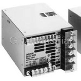
AC/DC Power Supply Single-OUT 12V 27A 300W Medical 12-Pin S82D-3012
AC/DC Power Supply Single-OUT 12V 1.2A 15W S82H-3112
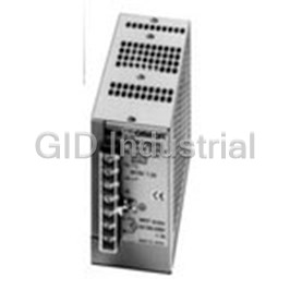
AC/DC Power Supply Single-OUT 24V 2.3A 50W Medical S82H-3524
AC/DC Power Supply Single-OUT 12V 1A 10W 5-Pin S82J01012D
AC/DC Power Supply Single-OUT 24V 0.5A 10W 5-Pin S82J-01024A
AC/DC Power Supply Single-OUT 5V 5A 25W S82J-0205
Request a Quote

The quote request has been received
Close

Facing challenges or have inquiries? Feel free to contact us!
Call Us +1-469-283-2440
What they say about us
FANTASTIC RESOURCE
One of our top priorities is maintaining our business with precision, and we are constantly looking for affiliates that can help us achieve our goal. With the aid of GID Industrial, our obsolete product management has never been more efficient. They have been a great resource to our company, and have quickly become a go-to supplier on our list!
Bucher Emhart Glass
EXCELLENT SERVICE
With our strict fundamentals and high expectations, we were surprised when we came across GID Industrial and their competitive pricing. When we approached them with our issue, they were incredibly confident in being able to provide us with a seamless solution at the best price for us. GID Industrial quickly understood our needs and provided us with excellent service, as well as fully tested product to ensure what we received would be the right fit for our company.
Fuji
HARD TO FIND A BETTER PROVIDER
Our company provides services to aid in the manufacture of technological products, such as semiconductors and flat panel displays, and often searching for distributors of obsolete product we require can waste time and money. Finding GID Industrial proved to be a great asset to our company, with cost effective solutions and superior knowledge on all of their materials, it’d be hard to find a better provider of obsolete or hard to find products.
Applied Materials
CONSISTENTLY DELIVERS QUALITY SOLUTIONS
Over the years, the equipment used in our company becomes discontinued, but they’re still of great use to us and our customers. Once these products are no longer available through the manufacturer, finding a reliable, quick supplier is a necessity, and luckily for us, GID Industrial has provided the most trustworthy, quality solutions to our obsolete component needs.
Nidec Vamco
TERRIFIC RESOURCE
This company has been a terrific help to us (I work for Trican Well Service) in sourcing the Micron Ram Memory we needed for our Siemens computers. Great service! And great pricing! I know when the product is shipping and when it will arrive, all the way through the ordering process.
Trican Well Service
GO TO SOURCE
When I can't find an obsolete part, I first call GID and they'll come up with my parts every time. Great customer service and follow up as well. Scott emails me from time to time to touch base and see if we're having trouble finding something.....which is often with our 25 yr old equipment.
ConAgra Foods