

 Manufacturers
OMRON AUTOMATION Y92H5

Description
Advanced Digital Controllers Ideal For Worldwide Use
Y92H5
Part Number
Y92H5
Price
Request Quote
Manufacturer
OMRON AUTOMATION
Lead Time
Request Quote
Category
Thermal Management » Misc Products
Specifications
Manufacturer
Omron Automation
Manufacturers Part #
Y92H5
Industry Aliases
Y92H-5
Sub-Categories
Miscellaneous Tools and Supplies
Factory Pack Quantity
1
Datasheet

Extracted Text
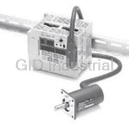
Digital Controller E5AK/E5EK Advanced Digital Controllers Ideal for Worldwide Use • Modular structure High-accuracy: 100 ms sampling (for analog input) Auto-tuning and fuzzy self-tuning Conforms to international EMC and safety standards. IP66/NEMA4 (indoor use) front face Remote set point Serial communications (RS-232C, RS-422 and RS-485) and transfer output (4 to 20 mA) ® Position-proportional control model Heating/cooling control AC/DC24V types are also available. Model Number Structure ■ Model Number Legend E5@K- @@@ @ -500 12 3 1. Size A: 96 × 96 mm E: 96 × 48 mm 2. Model AA: Standard model PRR: Position-proportional model 3. Number of alarms 2: Two alarms Digital Controller E5AK/E5EK 1 Ordering Information ■ List of Models Description Model Specification Base Unit E5AK-AA2 AC100-240 Standard model E5AK-AA2-500 AC100-240 Standard model with terminal cover E5AK-AA2 AC/DC24 Standard model E5AK-AA2-500 AC/DC24 Standard model with terminal cover E5AK-PRR2 AC100-240 Position-proportional model E5AK-PRR2-500 AC100-240 Position-proportional model with terminal cover E5AK-PRR2 AC/DC24 Position-proportional model E5AK-PRR2-500 AC/DC24 Position-proportional model with terminal cover E5EK-AA2 AC100-240 Standard model E5EK-AA2-500 AC100-240 Standard model with terminal cover E5EK-AA2 AC/DC24 Standard model E5EK-AA2-500 AC/DC24 Standard model with terminal cover E5EK-PRR2 AC100-240 Position-proportional model E5EK-PRR2-500 AC100-240 Position-proportional model with terminal cover E5EK-PRR2 AC/DC24 Position-proportional model E5EK-PRR2-500 AC/DC24 Position-proportional model with terminal cover Note: 1. When using the heater burnout alarm function with a standard model, the Linear Output Unit cannot be used for the control outputs (heat). 2. Be sure to specify the Current Transformer, Output Unit, and Option Unit when ordering. 3. The Digital Controller provides transfer outputs at 4 to 20 mA for the PV and other values and control outputs at 4 to 20 mA for the current outputs. Description Model Specification Output Unit E53-R Relay E53-S SSR E53-Q Pulse (NPN) 12 VDC E53-Q3 Pulse (NPN) 24 VDC E53-Q4 Pulse (PNP) 24 VDC E53-C3 Linear (4 to 20 mA) E53-C3D Linear (0 to 20 mA) E53-V34 Linear (0 to 10 V) E53-V35 Linear (0 to 5 V) Note: The Digital Controller uses a dedicated, high-resolution Output Unit. The E53-C Current Output Unit for the E5@X cannot be used with the Digital Controller. Description Model Specification Option Unit E53-AKB Event input E53-EN01 Communication (RS-232C) E53-EN02 Communication (RS-422) E53-EN03 Communication (RS-485) E53-AKF Transfer output Note: 1. The Option Unit can be used either by the E5AK or E5EK. 2. The E5AK allows a maximum of three Option Units to be mounted. Refer to page 8 for mounting combinations. The E5EK allows only one Option Unit to be mounted. Inspection Report The Digital Controller can be provided together with an inspection report. Refer to the following legend with the suffix “K” when ordering a model provided together with an inspection report. E5@K-AA2-K, E5@K-PRR2-K, E53-AKF-K 2 Digital Controller E5AK/E5EK ■ Accessories (Order Separately) Name Model Hole diameter Current Transformer E54-CT1 5.8 mm E54-CT3 12.0 mm Note: No CT is required unless the heater burnout alarm function is used. Name Model Connectable models Terminal Cover E53-COV0809 E5AK E53-COV08 E5EK Specifications ■ Ratings Item AC100-240V type AC/DC24V type Supply voltage AC100 to 240V, 50/60 Hz AC/DC24V, 50/60 Hz Power consumption E5AK: 16 VA 12 VA, 8 W E5EK: 15 VA Operating voltage range 85% to 110% of rated supply voltage Input Thermocouple: K, J, T, E, L, U, N, R, S, B, W, PLII Platinum resistance thermometer: JPt100, Pt100 Current input: 4 to 20 mA, 0 to 20 mA Voltage input: 1 to 5 V, 0 to 5 V, 0 to 10 V Input impedance Current input: 150 Ω; Voltage input: 1 MΩ min. Control output Standard Model According to Output Unit (see “Output Unit Ratings and Characteristics”) Position-proportional Model 2 Relay outputs: SPST-NO, 1 A at 250 VAC (including inrush current) (see note 1) Auxiliary output SPST-NO, 3 A at 250 VAC (resistive load) Control method (see note 2) ON/OFF or 2-PID control (with auto-tuning) Setting method Digital setting using front panel keys Indication method 7-segment digital display and LEDs Potentiometer 100 Ω to 2.5 kΩ Event input Contact input: ON: 1 kΩ max., OFF: 100 kΩ min. No-contact input: ON: residual voltage: 1.5 V max., OFF: leakage current: 0.1 mA max. Transfer output 4 to 20 mA, permissible load impedance: 600 Ω max., resolution: approx. 2,600 Remote SP input Current input: 4 to 20 mA (Input impedance: 150 Ω) Current Transformer input Connect an exclusive Current Transformer (E54-CT1 or E54-CT3) Other functions Standard Manual output, heating/cooling control, SP limiter, loop burnout alarm, SP ramp, MV limiter, MV change rate limiter, input digital filter, input shift, run/stop, protect functions Option Multiple SP, run/stop selection, transfer output functions Degree of protection Conforms to IEC IP66 and NEMA4 (Indoor use) Note: 1. All control outputs are insulated from the input circuit. 2. Fuzzy self-tuning is available when using the Digital Controller in standard control operation with temperature input. ■ Input Ranges Platinum Resistance Thermometer Input (switch selectable) JPt100 Pt100 Range °C −199.9 to 650.0 −199.9 to 650.0 °F −199.9 to 999.9 −199.9 to 999.9 Setting 01 Digital Controller E5AK/E5EK 3 Thermocouple Input (switch K1 K2 J1 J2 T E L1 L2 U N R S B W PLII selectable) (see note) Range °C −200 0.0 to −100 0.0 to −199.9 0 to −100 0.0 to −199.9 −200 0 to 0 to 100 to 0 to 0 to to 500.0 to 850 400.0 to 400.0 600 to 850 400.0 to 400.0 to 1,700 1,700 1,800 2,300 1,300 1,300 1,300 °F −300 0.0 to −100 0.0 to −199.9 0 to −100 0.0 to −199.9 −300 0 to 0 to 300 to 0 to 0 to to 900.0 to 750.0 to 700.0 1,100 to 750.0 to 700.0 to 3,000 3,000 3,200 4,100 2,300 2,300 1,500 1,500 2,300 Setting 2 3456 78 910 11 12 13 14 15 16 Note: Setting number is factory-set to 2 (K1). Thermocouple W is W/Re5-26 (tungsten rhenium 5, tungsten rhenium 26). Current/Voltage Input (switch selectable) Current input Voltage input 4 to 20 mA 0 to 20 mA 1 to 5 V 0 to 5 V 0 to 10 V Range One of following ranges depending on results of scaling −1999 to 9999 −199.9 to 999.9 −19.99 to 99.99 −1.999 to 9.999 Setting 17 18 19 20 21 4 Digital Controller E5AK/E5EK ■ Characteristics Indication accuracy (see note 1) Thermocouple: (±0.3% of indication value or ±1°C, whichever greater) ±1 digit max. Platinum resistance thermometer: (±0.2% of indication value or ±0.8°C, whichever greater) ±1 digit max. Analog input: ±0.2% FS ±1 digit max. Hysteresis 0.01% to 99.99% FS (in units of 0.01% FS) Proportional band (P) 0.1% to 999.9% FS (in units of 0.1% FS) Integral (reset) time (I) 0 to 3,999 s (in units of 1 s) Derivative (rate) time (D) 0 to 3,999 s (in units of 1 s) Control period 1 to 99 s (in units of 1 s) Manual reset value 0.0% to 100.0% (in units of 0.1%) Alarm setting range −1,999 to 9,999 or −199.9 or 999.9 (decimal point position dependent on input type or result of scaling) Sampling period (see note 2) Temperature input: 250 ms Current/voltage input: 100 ms Insulation resistance 20 MΩ min. (at 500 VDC) Dielectric strength 2,000 VAC, 50/60 Hz for 1 min between terminals of different polarities 2 Vibration resistance Malfunction: 10 to 55 Hz, 10 m/s (approx. 1G) for 10 min each in X, Y, and Z directions 2 Destruction: 10 to 55 Hz, 20 m/s (approx. 2G) for 2 hrs each in X, Y, and Z directions 2 Shock resistance Malfunction: 200 m/s min. (approx. 20G), 3 times each in 6 directions 2 (100 m/s (approx. 10G) applied to the relay) 2 Destruction: 300 m/s min. (approx. 30G), 3 times each in 6 directions Ambient temperature Operating: −10°C to 55°C (with no icing)/3-year warranty period: –10°C to 50°C Storage: −25°C to 65°C (with no icing) Ambient humidity Operating: 35% to 85% Degree of protection Front panel: NEMA4 for indoor use (equivalent to IP66) Rear case: IEC standard IP20 Terminals: IEC standard IP00 Memory protection Non-volatile memory (number of writings: 100,000 operations) Weight E5AK: approx. 450 g E5EK: approx. 320 g Mounting bracket: approx. 65 g EMC Emission Enclosure: EN55011 Group 1 class A Emission AC Mains: EN55011 Group 1 class A Immunity ESD: EN61000-4-2: 4 kV contact discharge (level 2) 8 kV air discharge (level 3) Immunity RF-interference: ENV50140: 10 V/m (amplitude modulated, 80 MHz to 1 GHz) (level 3) 10 V/m (pulse modulated, 900 MHz) Immunity Conducted Disturbance: ENV50141: 10 V (0.15 to 80 MHz) (level 3) Immunity Burst: EN61000-4-4: 2 kV power-line (level 3) 2 kV I/O signal-line (level 4) Approved standards UL1092, CSA22.2 No. 142, CSA22.2 No. 1010-1 Conforms to EN50081-2, EN50082-2, EN61010-1 (IEC1010-1) Conforms to VDE0106/part 100 (Finger Protection), when the separately-ordered terminal cover is mounted. Note: 1. The indication accuracy of the K1, T, and N thermocouples at a temperature of −100°C or less is ±2°C ±1 digit maximum. The indication accuracy of the U, L1, and L2 thermocouples at any temperature is ±2°C ±1 digit maximum. The indication accuracy of the B thermocouple at a temperature of 400°C or less is unrestricted. The indication accuracy of the R and S thermocouples at a temperature of 200°C or less is ±3°C ±1 digit maximum. The indication accuracy of the W thermocouple at any temperature is (±0.3% of the indicated value or ±3°C, whichever is greater) ±1 digit maximum. The indication accuracy of the PLII thermocouple at any temperature is (±0.3% or ±2°C, whichever is greater) ±1 digit maximum. 2. The sampling period of the standard model with CT and remote SP inputs is 250 ms. Digital Controller E5AK/E5EK 5 ■ Output Unit Ratings and Characteristics Relay output 5 A at 250 VAC (resistive load) SSR output 1 A at 75 to 250 VAC (resistive load) Voltage output NPN: 40 mA at 12 VDC (with short-circuit protection) NPN: 20 mA at 24 VDC (with short-circuit protection) PNP: 20 mA at 24 VDC (with short-circuit protection) Linear current output 4 to 20 mA, permissible load impedance: 600 Ω max., resolution: approx. 2,600 0 to 20 mA, permissible load impedance: 600 Ω max., resolution: approx. 2,600 Linear voltage output 0 to 10 VDC, permissible load impedance: 1 kΩ max., resolution: approx. 2,600 0 to 5 VDC, permissible load impedance: 1 kΩ max., resolution: approx. 2,600 Note: An output relay (1 A at 250 VAC) is mounted on the position-proportional model. (When replacing, use the E53-R.) ■ Option Unit Ratings and Characteristics Event inputs Contact input: ON: 1 kΩ max., OFF: 100 kΩ min. No-contact input: ON: residual voltage 1.5 V max., OFF: leakage current 0.1 mA max. Communications Interface: RS-232C, RS-422 or RS-485 Transmission method: Half-duplex Synchronization method: Start-stop synchronization (asynchronous method) Baud rate: 1.2/2.4/4.8/9.6/19.2 kbps Transmission code: ASCII Transfer output 4 to 20 mA: Permissible load impedance: 600 Ω max. Resolution: approx. 2,600 ■ Current Transformer Ratings Dielectric strength 1,000 VAC (for 1 min) 2 Vibration resistance 50 Hz, 98 m/s (10G) Weight E54-CT1: approx. 11.5 g; E54-CT3: approx. 50 g Accessories (E54-CT3 only) Armature: 2; Plug: 2 ■ Heater Burnout Alarm Max. heater current Single-phase 50 A VAC (see note 1) Heater current value display accuracy ±5% FS±1 digit max. Heater burnout alarm setting range 0.1 to 49.9 A (in units of 0.1 A) (see note 2) Min. detection ON time 190 ms (see note 3) Note: 1. Use the K2CU-F@@A-@GS (with gate input terminals) for the detection of three-phase heater burnout. 2. The heater burnout alarm is always OFF if the alarm is set to 0.0 A and always ON if the alarm is set to 50.0 A. 3. No heater burnout detection or heater current value measurement is possible if the control output (heat) is ON for less than 190 ms. 6 Digital Controller E5AK/E5EK Nomenclature E5AK Operation Indicators No. 1 Display • OUT1 Displays the process value or pa- Lights when the pulse output rameter symbols. function assigned to control output No. 2 Display 1 turns ON. Displays the set point, manipulated • OUT2 variable, or parameter settings. Lights when the pulse output function assigned to control output 2 turns ON. • SUB1 Lights when the output function assigned to auxiliary output 1 turns ON. • SUB2 Lights when the output function assigned to auxiliary output 2 turns ON. • MANU Lights when the manual operation mode. • STOP Lights during operation has stopped. • RMT Lights during remote operation. • AT Flashes during auto-tuning. • RSP Lights during remote SP opera- Up Key/Down Key tion. Press to increase or decrease the • Bar Graph value on the No.2 display. On a standard model (E5AK- AA2), this bar graph indicates the Display Key manipulated variable (heat) in Press for less than 1 s to shift the 10% increments per single seg- display to the next parameter. When ment. On a position-proportional this key is pressed for 1 s or more, model (E5AK-PRR2), this bar the menu screen will be displayed in graph indicates the valve opening any case. in 10% increments per single seg- A/M Key ment. Press to select the auto operation or manual operation. E5EK No. 1 display No. 2 display Operation indicators Display Key A/M Key Up Key/Down Key Digital Controller E5AK/E5EK 7 Dimensions Note: All units are in millimeters unless otherwise indicated. E5AK Panel Cutouts 110 min. 96 × 96 120 min. Note: 1. Recommended panel thickness is 1 to 8 mm. 2. Maintain the specified vertical and horizontal mounting space between each Unit. Units must not be closely mounted vertically or horizontally. E5EK Panel Cutouts 60 min. 120 min. Note: 1. Recommended panel thickness is 1 to 8 mm. 2. Maintain the specified vertical and horizontal mounting space between each Unit. Units must not be closely mounted vertically or horizontally. Accessories (Order Separately) Terminal Cover E53-COV0809 E53-COV08 8 Digital Controller E5AK/E5EK 91 × 91 Current Transformer E54-CT1 E54-CT3 2.36 dia. 12 dia. 5.8 dia. 40x40 Two, M3 (depth: 4) Installation Note: Always turn off the power supply to the Digital Controller before changing any switch settings. Setting Up the Option Unit ■ Settings •E5AK On a standard model, set up the Output Units for control outputs 1 1. Remove the power board and option boards in the order shown in and 2 before mounting the Controller. the following diagram. On a position-proportional model, the Relay Output Unit is already set. Therefore, this setup operation is unnecessary. (Do not replace with other Output Units.) When setting up the Output Units, draw out the internal mechanism from the housing and insert the Output Units into the sockets for con- trol outputs 1 and 2. Setting Up the Output Unit 2. Insert the Option Units into the sockets for options 1 to 3. The fol- Removing the Output Unit lowing diagram shows the relationship between the Option Units and mounting positions. To replace the Output Unit, use a flat-blade screwdriver to push up the Output Unit. Option 1 E53-AKB: Event inputs 1/2 E53-EN01: RS-232C E53-EN02: RS-422 E53-EN03: RS-485 3. Mount the option boards and the power board in the order shown. Digital Controller E5AK/E5EK 9 E5EK Draw-out 1. Remove the power board and option boards in the order shown in To draw out the internal mechanism from the housing, use a Phillips the following diagram. screwdriver matching the screw on the lower part of the front panel. 1. Turn the screw counterclockwise while pressing the hook on the upper part of the front panel. Hook 2. Draw out the internal mechanism while holding the left and right sides of the front panel. Mounting 1. Insert the E5AK Controller into the panel’s mounting hole at the position shown in the figure below. 2. Insert the Option Unit into the socket for option 1. The following 2. Fit the mounting bracket (accessory) into the fixing slots on the diagram shows the relationship between the Option Unit and top and bottom of the rear case. mounting position. Option 1 E53-AKB: Event inputs 1/2 E53-EN01: RS-232C E53-EN02: RS-422 E53-EN03: RS-485 E53-AKF: Transfer output 3. Tighten the mounting bracket screws on the upper and lower parts of the E5AK in small increments alternately and equally until the ratchet start to slide. 3. Mount the option board and the power board in the order shown. 10 Digital Controller E5AK/E5EK E53-COV0809, E53-COV08 Terminal Cover (Sold Separately) Fasten the terminals covers as follows by using the snap pins. Snap pins are provided with the terminal covers. Digital Controller E5AK/E5EK 11 Wiring ■ Wiring Terminals for E5AK Terminal Arrangement AC100-240V~ (AC/DC24V~) SOURCE TRSF: Transfer output EV1 to 4: Event input PTMR: Potentiometer RSP: Remote SP input Wiring In the following wiring diagrams, the left side of the terminal numbers indicate the inside of the Controller. Power Supply Input 100 to 240 VAC or AC/DC 24 V to terminal numbers 9 and 10 according to the specifications. Sensor Input Connect the sensor input to terminal numbers 11 to 14 and 33 as follows according to the input type. 12 Digital Controller E5AK/E5EK Control Output Terminal numbers 7 and 8 are for control output 1 (OUT1), and terminal numbers 5 and 6 are for control output 2 (OUT2). The following diagrams show the available Output Units and their internal equalizing circuits. With E53-V@@ Output Units, approx. 2 V is output for one second after the power is interrupted. The following table shows the specifications for each Output Unit. Model Output type Specifications E53-R Relay 5 A at 250 VAC E53-S SSR 1 A at 75 to 250 VAC E53-Q Voltage (NPN) NPN: 40 mA at 12 VDC (with short-circuit protection) E53-Q3 Voltage (NPN) NPN: 20 mA at 24 VDC (with short-circuit protection) E53-Q4 Voltage (PNP) PNP: 20 mA at 24 VDC (with short-circuit protection) E53-C3 4 to 20 mA 4 to 20 mA; permissible load impedance: 600 Ω max.; resolution: approx. 2600 E53-C3D 0 to 20 mA 0 to 20 mA; permissible load impedance: 600 Ω max.; resolution: approx. 2600 E53-V34 0 to 10 V 0 to 10 VDC; permissible load impedance: 1 kΩ min.; resolution: approx. 2600 E53-V35 0 to 5 V 0 to 5 VDC; permissible load impedance: 1 kΩ min.; resolution: approx. 2600 With E5AK-PRR2 Controllers, the relay output (1 A at 250 VAC) is fixed. When replacing the Output Unit, use the E53-R. The following diagrams show the relationship between terminals and open/close relay settings. 8 6 7 5 Open Close Auxiliary Output Terminal numbers 3 and 4 are for auxiliary output 1 (SUB1) and terminal numbers 1 and 2 are for auxiliary output 2 (SUB2). The following diagrams show the internal equalizing circuits for the auxiliary outputs: 10 30 20 31 32 9 29 19 8 28 18 7 27 17 4 2 6 26 16 5 25 15 4 24 14 3 1 3 23 13 Auxiliary Auxiliary 2 22 12 output 1 output 2 33 1 21 11 Output specifications are as follows: SPST-NO, 3 A at 250 VAC Digital Controller E5AK/E5EK 13 CT Input/Potentiometer When using the HBA function on the E5AK-AA2 Controller, connect CT input (CT) to terminal numbers 15 to 17. When monitoring the valve opening on the E5AK-PRR2 Controller, connect the potentiometer (PTMR) to terminal numbers 15 to 17. Connect each of these inputs as follows: 10 30 20 31 32 9 29 19 8 28 18 7 27 17 O 17 17 6 26 16 W 16 CT 16 5 25 15 C 15 15 4 24 14 3 23 13 CT input Potentiometer 2 22 12 33 1 21 11 For details on CT inputs, refer to Appendix, About Current Transformer in the E5AK/E5EK User’s Manual (H83/H85). For details on the potentiom- eter, refer to the Instruction Manual for the valve connected to the Controller. The variable resistance range is 100 Ω to 2.5 kΩ. Remote SP Input Connect the input (RSP) to be used as the remote SP to terminal numbers 21 and 22. Only 4 to 20 mA inputs can be connected. Connect the input as follows: 10 30 20 31 32 9 29 19 8 28 18 7 27 17 + 6 26 16 22 5 25 15 4 to 20 mA 4 24 14 21 − 3 23 13 2 22 12 33 1 21 11 14 Digital Controller E5AK/E5EK Event Input Connect event inputs 1 and 2 (EV1/2) to terminal numbers 18 to 20, and event events 3 and 4 (EV3/4) to terminal numbers 24 to 26. However, note that terminal numbers 18 to 20 cannot be used on Controllers with a communications function. Connect the event inputs as follows: 10 30 20 31 32 9 29 19 8 28 18 + + 20 26 EV1 EV3 7 27 17 + + 6 26 16 19 25 EV2 EV4 5 25 15 COM 18 COM 24 − − 4 24 14 Event input 1 and 2 Event input 3 and 4 3 23 13 2 22 12 33 1 21 11 Terminals 18 and 24 (COM) are connected internally. Use event inputs under the following conditions: Contact input ON: 1 kΩ max. OFF: 100 kΩ min. No-contact input ON: Residual voltage 1.5 V max., OFF: Leakage current 0.1 mA max. Polarities during no-contact input are as follows: + + 20 26 EV1 EV3 + + 25 EV2 19 EV4 COM COM 24 18 − − Event input 1 and 2 Event input 3 and 4 Transfer Output Connect transfer output (TRSF) to terminal numbers 29 and 30. The internal equalizing circuit for transfer output is as follows: + 30 L 4 to 20mA 29 − Transfer output specifications are as follows: 4 to 20 mA, Permissible load impedance: 600 Ω max., Resolution: Approx. 2600 Communications Terminal numbers 18 to 20, 31 and 32 can be used only on Controllers with Communications Units (E53-EN01/02/03). For details on wiring, refer to Chapter 6, Using the Communications Function in the E5AK/E5EK User’s Manual (H83/H85). Digital Controller E5AK/E5EK 15 ■ Wiring Terminals for E5EK Terminal Arrangement AC100-240V~ (AC/DC24V~) SOURCE TRSF: Transfer output EV1/2: Event input PTMR: Potentiometer RSP: Remote SP input Wiring In the following wiring diagrams, the left side of the terminal numbers indicate the inside of the Controller. Power Supply Input 100 to 240 VAC or AC/DC 24 V to terminal numbers 9 and 10 according to the specifications. Sensor Input Connect the sensor input to terminal numbers 11 to 14 and 33 as follows according to the input type. 16 Digital Controller E5AK/E5EK Control Output Terminal numbers 7 and 8 are for control output 1 (OUT1), and terminal numbers 5 and 6 are for control output 2 (OUT2). The following diagrams show the available Output Units and their internal equalizing circuits. With E53-V@@ Output Units, approx. 2 V is output for one second after the power is interrupted. The following table shows the specifications for each Output Unit. Model Output type Specifications E53-R Relay 5 A at 250 VAC E53-S SSR 1 A at 75 to 250 VAC E53-Q Voltage (NPN) NPN: 40 mA at 12 VDC (with short-circuit protection) E53-Q3 Voltage (NPN) NPN: 20 mA at 24 VDC (with short-circuit protection) E53-Q4 Voltage (PNP) PNP: 20 mA at 24 VDC (with short-circuit protection) E53-C3 4 to 20 mA 4 to 20 mA, permissible load impedance: 600 Ω max., resolution: approx. 2600 E53-C3D 0 to 20 mA 0 to 20 mA, permissible load impedance: 600 Ω max., resolution: approx. 2600 E53-V34 0 to 10 V 0 to 10 VDC, permissible load impedance:1 kΩ min., resolution: approx. 2600 E53-V35 0 to 5 V 0 to 5 VDC, permissible load impedance: 1 kΩ min., resolution: approx. 2600 With E5EK-PRR2 Controllers, the relay output (1 A at 250 VAC) is fixed. When replacing the Output Unit, use the E53-R. The following diagrams show the relationship between terminals and open/close relay settings. 8 6 7 5 Open Close Auxiliary Output Terminal numbers 3 and 4 are for auxiliary output 1 (SUB1) and terminal numbers 1 and 2 are for auxiliary output 2 (SUB2). The following diagrams show the internal equalizing circuits for the auxiliary outputs: 10 20 21 22 9 19 8 18 42 7 17 6 16 1 5 15 Auxiliary Auxiliary 4 14 output 1 output 2 3 13 2 12 23 1 11 Output specifications are as follows: SPST-NO, 3A at 250 VAC Digital Controller E5AK/E5EK 17 CT Input/Potentiometer When using the HBA function on the E5EK-AA2 Controller, connect CT input (CT) to terminal numbers 15 to 17. When monitoring the valve opening on the E5EK-PRR2 Controller, connect the potentiometer (PTMR) to terminal numbers 15 to 17. Connect each of these inputs as follows: 10 20 21 22 9 19 O 17 17 8 18 W 16 16 7 17 C 6 16 15 15 5 15 CT input Potentiometer 4 14 3 13 2 12 23 1 11 For details on CT inputs, refer to Appendix, About Current Transformer in the E5AK/E5EK User’s Manual (H83/H85). For details on the potentiom- eter, refer to the Instruction Manual for the valve connected to the Controller. The variable resistance range is 100 Ω to 2.5 kΩ. Remote SP Input Connect the input (RSP) to be used as the remote SP to terminal numbers 15 and 16. However, note that the remote SP cannot be used on the E5EK-PRR2 Controller. Only 4 to 20 mA inputs can be connected. Connect the input as follows: 10 20 21 22 9 19 + 16 8 18 7 17 4 to 20 mA 6 16 15 − 5 15 4 14 3 13 2 12 23 1 11 Event Input Connect event inputs 1 and 2 (EV1/2) to terminal numbers 18 to 20. However, note that terminal numbers 18 to 20 cannot be used on Controllers with a communications function. Connect the event inputs as follows: 10 20 21 22 + 9 19 20 EV1 + 8 18 19 EV2 7 17 18 COM − 6 16 Event input 1 and 2 5 15 4 14 3 13 2 12 23 1 11 Use event inputs under the following conditions: Contact input ON: 1 kΩ max., OFF: 100 kΩ min. No-contact input ON: Residual voltage 1.5 V max., OFF: Leakage current 0.1 mA max. 18 Digital Controller E5AK/E5EK Polarities during no-contact input are as follows: + 20 EV1 + 19 EV2 COM 18 − Event input 1 and 2 Transfer Output Connect transfer output (TRSF) to terminal numbers 21 and 22. The internal equalizing circuit for transfer output is as follows: + 21 4 to 20mA L 22 − Transfer output specifications are as follows: 4 to 20 mA, Permissible load impedance: 600 Ω max., Resolution: Approx. 2600 Communications Terminal numbers 18 to 22 can be used only on controllers with Communications Units (E53-EN01/02/03). For details on wiring, refer to Chapter 6, Using the Communications Function in the E5AK/E5EK User’s Manual (H83/H85). ■ Precautions when Wiring Use ducts to separate input leads and power lines in order to protect the Controller and its lines from external noise. Solderless terminals are recommended when wiring the Controller. Tighten the terminal screws using a torque no greater than 0.78 N·m, or 8 kgf·cm max. Take care not to tighten the terminal screws too tightly. Power Blocks The E5AK/E5EK has independent power supplies for each of the terminal blocks shown below. E5EK E5AK AB C AB/C C 10 20 10 30 20 31 32 21 22 9 29 19 9 19 8 8 28 18 18 7 27 7 17 17 B B 6 6 26 16 16 C 5 5 25 15 15 4 4 24 14 14 E E 3 23 3 13 13 2 22 12 2 12 1 33 23 21 11 1 11 FD FD Note: Terminals 21 and 22 of the E5EK belong to the B block when a transfer output is set to option 1 and to the C block for other Op- tion Units. Digital Controller E5AK/E5EK 19 Operation ■ After Turning ON Power ■ Input Type Determine the I/O specifications of the Digital Controller in setup Set the code according to the following table. Default is “2: K1 ther- mode. mocouple.” Power ON Platinum Resistance Thermometer Set Input type value Process value 0 JPt100 −199.9 to 650.0 (°C) Platinum resistance ther- /−199.9 to 999.9 (°F) mometer 1 s min. 1 Pt100 −199.9 to 650.0 (°C) /−199.9 to 999.9 (°F) 2K1 −200 to 1,300 (°C) Thermocouple /−300 to 2,300 (°F) 3 K2 0.0 to 500.0 (°C) /0.0 to 900.0 (°F) 4J1 −100 to 850 (°C) /−100 to 1,500 (°F) 5 J2 0.0 to 400.0 (°C) /0.0 to 750.0 (°F) 6T −199.9 to 400.0 (°C) /−199.9 to 700.0 (°F) 7 E 0 to 600 (°C) /0 to 1,100 (°F) 8L1 −100 to 850 (°C) 1 s min. /−100 to 1,500 (°F) 9 L2 0.0 to 400.0 (°C) Input type /0.0 to 750.0 (°F) 10 U −199.9 to 400.0 (°C) Temperature input Current/Voltage input /−199.9 to 700.0 (°F) 11 N −200 to 1,300 (°C) /−300 to 2,300 (°F) °C/°F Scaling selection upper limit 12 R 0 to 1,700 (°C) /0 to 3,000 (°F) 13 S 0 to 1,700 (°C) /0 to 3,000 (°F) Scaling lower limit 14 B 100 to 1,800 (°C) /300 to 3,200 (°F) 15 W 0 to 2,300 (°C) /0 to 4,100 (°F) Decimal point 16 PLII 0 to 1,300 (°C) /0 to 2,300 (°F) 17 4 to 20 mA Current input 18 0 to 20 mA 19 1 to 5 V Voltage input Parameter initialize 20 0 to 5 V 21 0 to 10 V From next page To next page 20 Digital Controller E5AK/E5EK Standard Models ■ Parameter Initialize Control Auxiliary Parameter initialization sets all parameters to default values except Assignment output output for the input type, scaling upper limit, scaling lower limit, decimal destination point, and °C/°F selection parameters. 12 12 Output function To previous page From previous page Control output (heat) Yes Yes --- --- Control output (cool) Yes Yes --- --- Control output 1 Alarm 1 Yes Yes Yes Yes assignment (Not displayed by the Alarm 2 Yes Yes Yes Yes E5@K-PRR2) Alarm 3 Yes Yes Yes Yes Control output 2 HBA Yes Yes Yes Yes assignment (Not displayed by the LBA Yes Yes Yes Yes E5@K-PRR2) Output assignment Error 1: Input error --- --- Yes Yes Auxiliary output 1 Error 2: A/D converter error --- --- Yes Yes assignment Error 3: RSP input error --- --- Yes Yes Auxiliary output 2 With control output (cool), the conditions for switching from assignment standard control to heating and cooling control are reached when the output function is assigned at the cooling side during heating and cooling control. Alarm 1 type In other words, heating and cooling control is carried out when con- trol output (cool) is assigned, and standard control is carried out when output is not assigned. Alarm 1 open in alarm Position-proportional Models Alarm Control Auxiliary Assignment 1, 2, or Alarm 2 type output output 3 is not destination Alarm type set. 12 12 Output function Alarm 2 Alarm 1 --- --- Yes Yes open in alarm Alarm 2 --- --- Yes Yes Alarm 3 --- --- Yes Yes Error 1: Input error --- --- Yes Yes Alarm 3 type Error 2: A/D converter error --- --- Yes Yes Error 3: RSP input error --- --- Yes Yes Alarm 3 open in alarm LBA The LBA (loop break alarm) function is available when it is assigned Direct/Reverse as an output. The LBA function is not available when a memory or A/ operation D converter error results. LBA is a function for determining that an error has occurred some- where on the control loop and outputting an alarm when the process value does not change with the manipulated variable at a maximum ■ Output Assignments or minimum state. Accordingly, the LBA function can be used as a means for detecting a malfunctioning control loop. Signals available as allocated outputs are the control output (heat), control output (cool), alarm 1, alarm 2, alarm 3, LBA, and HBA. The auxiliary outputs of the Digital Controller cannot be used as control outputs. Control output (heat), control output (cool), alarm 1, alarm 2, alarm 3, LBA, error 1 (input error), error 2 (A/D converter error), and error 3 (RSP input error) output functions are available. These functions are assigned to control outputs 1 and 2 and auxiliary outputs 1 and 2. The assignment destination of each output function is may be restricted. Refer to the following table. Digital Controller E5AK/E5EK 21 ■ Alarm Mode Selectors Alarm outputs are available if they are allocated as outputs. Factory setting is “2: Upper-limit alarm (deviation).” Switch Alarm operation Alarm output setting When X is positive When X is negative 1 Upper- and lower-limit alarm (deviation) Always ON XX ON OFF SP 2 Upper-limit alarm (deviation) X X ON ON OFF OFF SP SP 3 Lower-limit alarm (deviation) X X ON ON OFF OFF SP SP 4 Upper- and lower-limit range alarm (deviation) Always OFF XX ON OFF SP 5 Upper- and lower-limit alarm with standby se- Always OFF XX ON quence (deviation) OFF SP 6 Upper-limit alarm with standby sequence (devia- X X ON ON tion) OFF OFF SP SP 7 Lower-limit alarm with standby sequence (devia- X X ON tion) ON OFF OFF SP SP 8 Absolute-value upper-limit alarm X X ON ON OFF OFF 0 0 9 Absolute-value lower-limit alarm X X ON ON OFF OFF 0 0 10 Absolute-value upper-limit alarm with standby se- X X ON ON quence OFF OFF 0 0 11 Absolute-value lower-limit alarm with standby se- X X ON ON quence OFF OFF 0 0 When selecting a control method, refer to the following table for cor- Deviation Alarm rect parameter setting. If the alarm mode selector is set to a number between 1 to 7, alarm values are set to the width deviated from the set point as shown in Control Control output Control output Operation method 1 assignment 2 assignment the following illustration. Heat Control output --- Reverse Alarm value (heat) 10°C/°F Cool Control output --- Direct (heat) Heat/Cool Control output Control output Reverse 110°C/°F (heat) (cool) Set point (SP) 100°C/°F Absolute Alarm If the alarm mode selector is set to 8 or 9, alarm values are set to the absolute value based on 0°C/°F as shown in the following illustration. Alarm value 110°C/°F 0°C/°F 110°C/°F 22 Digital Controller E5AK/E5EK ■ Close in Alarm/Open in Alarm When the Controller is set to “close in alarm,” the status of the alarm output function is output as it is. When set to “open in alarm,” the sta- tus of the alarm output function is output inverted. Condition Alarm Output Output LED Close in alarm ON ON Lit OFF OFF Not lit Open in alarm ON OFF Lit OFF ON Not lit Alarm type and close in alarm (normally open)/open in alarm (nor- mally close) can be set independently from each alarm. Close in alarm/Open in alarm is set in the “alarm 1 to 3 open in alarm” parameters (setup mode). Factory setting is “close in alarm” [n-o ]. ■ Parameter Operation List Switching to modes other than manual or protect mode is carried out using the mode selection in the menu display. The figure below shows all parameters in the order that they are displayed. Some parameters are not displayed depending on the protect mode setting and conditions of use. Power ON A/M 1 second min. 1 second min. Level 0 mode Manual mode 1 second min. A/M Level 1 mode 1 second min. 1 second min. Level 2 mode A/M ++ A/M 1 second min. 1 second min. 1 second min. Setup mode Protect mode 1 second min. Expansion mode A/M + 1 second min. 1 second min. Option mode Parameters in a mode can be switched by the Display Key. The 1 second min. parameter following the last param- Calibration mode eter is the top parameter. Note: The control of the Digital Controller is reset when the Digital Controller is in setup, expansion, option, or calibration mode, in which case the control and auxiliary outputs are OFF. The reset condition will be canceled when the Digital Controller is in any mode other than the above. ■ Parameters and Menus Note: For more details on the functions of each part and display contents, refer to the E5AK/E5EK User’s Manual (H83/H85). All functions selected with the Digital Controller in setup or expansion mode or all optional functions of the Digital Controller may not be displayed. Protect Mode Limits use of the menu and A/M Keys. The protect function prevents unwanted modification of parameters and switching between the auto and manual operation. Manual Mode The Controller can be switched to manual operation. The manipulated variable can be manipulated manually only in this mode. Digital Controller E5AK/E5EK 23 Level 0 Mode Set the Controller to this mode during normal operation. In this mode, change the set point during operation, and start or stop Controller operation. The process value, ramp SP, and manipulated variable can only be monitored in this mode. Level 1 Mode The main mode for adjusting control. In this mode, execute AT (auto-tuning), and set alarm values, the control pe- riod, and PID parameters. Level 2 Mode The auxiliary mode for adjusting control. In this mode, set the parameters for limiting the manipulated variable and set point, switch between the remote and local modes, switch between the SP mode, and set the loop break alarm (LBA), alarm hysteresis, and the digital filter value of inputs. Setup Mode The mode for setting the basic specifications. In this mode, set parameters that must be checked or set before operation such as the input type, scaling, output assignments and direct/reverse operation. Expansion Mode The mode for setting expanded functions. In this mode, set ST (self-tuning), SP setting limiter, select advanced PID or ON/OFF control, specify the standby sequence resetting method, and set the time for automatic return to the monitoring display. Option Mode The mode for setting option functions. Select this mode only when the Option Unit is set in the Controller. In this mode, set the communications conditions, transfer output and event input parameters to match the type of Option Unit set in the Controller. Heater burnout latch function, position-proportional travel time, and remote SP scaling parameter are also located in this mode. Calibration Mode The mode for calibrating inputs and transfer output. When calibrating input, the selected input type is calibrated. Whereas, transfer output can be calibrated only when the Communications Unit (E53-CKF) is set in the Controller. ■ Parameter Operation Refer to the E5AK/E5EK User’s Manual (H83/H85) for each parameter and the calibration mode in detail. Refer to page 9 for the setting in detail. Level 0 Mode SP Ramp With the SP ramp function, the Controller operates according to the value (set point during SP ramp) limited by a change rate, instead of the changed set point when the set point is changed. The interval in Process value PV/SV (local SP/remote SP) which the set point during SP ramp is limited is referred to as the “SP ramp.” Set point during SP ramp SP ramp Set point For E5@K-PRR2 SP ramp set value MV monitor (heat) Valve opening Manipulated SP ramp time unit monitor variable Time Switching point (Heat/Cool) The change rate during the SP ramp is specified by the “SP ramp set MV monitor value” and “SP ramp time unit” parameters. At the “SP ramp set (cool) Manipulated value” default “0,” the SP ramp function is disabled. variable The set point changing in SP ramp can be monitored in the “Set point during SP ramp” parameter (level 0 mode). Run/Stop PV/SV The process value is displayed on the No.1 display and the set point is displayed on the No.2 display. When the multi-SP function is in use, the value of whichever is set, set point 0 or 1, is linked. Remote SP Monitor Monitors remote SP in the local SP mode. Set Point During SP Ramp Monitors the set point when the SP ramp function is used. 24 Digital Controller E5AK/E5EK Protect Mode Manual Mode 1 s min. Press twice for 1 s min. Process value Security Manipulated variable/ Valve opening MANU indicator Bar graph (see note) A/M Key protect Note: Only for E5AK 1 s min. To level 0 Press twice for 1 s min. Security Any mode marked with “X” in the following table is not displayed on the menu when this parameter is set to “0” to “3.” Mode Set value 01234 Calibration --- xxxx Option --- --- x x x Expansion --- --- x x x Setup --- --- x x x Level 2 --- --- --- x x Level 1, 0 --- --- --- --- x The Unit will be in only level 0 mode and the menu will not be avail- able when this parameter is set to “4” to “6.” Only the “PV/SP” parameter in the level 0 mode can be used when this parameter is set to “5.” Only the “PV/SP” parameter in the level 0 mode can be used when this parameter is set to “6.” A/M Key Protect Invalidate the function of the A/M Key. Digital Controller E5AK/E5EK 25 Level 1 Mode Level 2 Mode Remote/Local Used for the AT Execute/Cancel communications function. Set Point 0 Used with multi-SP function. SP Mode Set Point 1 Used with multi-SP function. SP Ramp Time Unit Set Point 2 Used with multi-SP function. SP Ramp Set Value Set Point 3 LBA Detection Time Used with multi-SP function. Available when the LBA (loop break alarm) is assigned as an output. Unavailable to the E5@K-PRR2. Alarm Value 1 Available only when the alarm output 1 is assigned. MV at Stop Alarm Value 2 Available only when the alarm output 2 is assigned. MV at PV Error Alarm Value 3 Available only when the alarm output 3 is assigned. MV Upper Limit Unavailable to the E5@K-PRR2. Proportional Band Available if the Controller is in advanced PID control. MV Lower Limit Unavailable to the E5@K-PRR2. Integral Time Available if the Controller is in advanced PID control. MV Change Rate Limit Derivative Time Available if the Controller is in advanced PID control. For E5@K-PRR2 Input Digital Filter For heating/cooling control Cooling Coefficient Used with the Controller is in For E5@K-PRR2 heating and cooling control. Position- proportional Dead Band dead band Used with the Controller is in heating and cooling control. Open/Close hysteresis Alarm 1 Hysteresis Manual Reset Value Available only when the alarm Available when the integral time parameter output 1 is assigned. of the Controller in standard control is "0". Alarm 2 Hysteresis Hysteresis (Heat) Available only when the alarm Available when the Controller is in output 2 is assigned. ON/OFF control. Alarm 3 Hysteresis For heating/cooling control Available only when the alarm Hysteresis (Cool) output 3 is assigned. Available when the Controller is in ON/OFF control Input Shift Upper Limit Available if the input type is a Control Period (Heat) thermocouple or platinum resistance Available when the Controller has a relay or thermometer. voltage output, or is in advanced PID control. (See Input Shift) Input Shift Lower Limit For heating/cooling control Available if the input type is a Control Period (Cool) thermocouple or platinum resistance Available when the Controller has a relay thermometer. or voltage output, or is in advanced PID control. Heater Current Monitor Available when the heater Current value burnout alarm is assigned. Heater Burnout Detection Available when the heater burnout alarm is assigned. 26 Digital Controller E5AK/E5EK Input Shift Setup Mode When temperature input is selected, scaling is not required. This is because input is treated as the “temperature” as it is matched to the input type. However, note that the upper- and lower-limit values of the Input type sensor can be shifted. For example, if both the upper- and lower-limit values are shifted by 1.2°C, the process value (before shift) is regarded as 201.2°C after shift when input is 200°C before shift. Temperature input Current/Voltage input To set the input shift, set shift values in the “input shift upper limit” and “input shift lower limit” parameters (level 2 mode). Scaling °C/°F upper limit selection Temperature Upper-limit compensation value Upper limit After Scaling compensation lower limit Before compensation Lower-limit compensation value Lower limit Input (% of full scale) Decimal point Parameter initialize Control output 1 assignment (Not displayed by the E5@K-PRR2) Control output 2 assignment (Not displayed by the E5@K-PRR2) Output assignment Auxiliary output 1 assignment Auxiliary output 2 assignment Alarm 1 type Alarm 1 open in alarm Alarm 1, 2, or Alarm 2 type 3 is not set. Alarm type Alarm 2 open in alarm Alarm 3 type Alarm 3 open in alarm Direct/Reverse operation Digital Controller E5AK/E5EK 27 Expansion Mode Option Mode Multi-SP Function Set point Available for the event input functions. Upper Limit Event Input Assignment 1 Available for the event input function. Set point Lower Limit Event Input Assignment 2 PID/ON/OFF Available for the event input function. Unavailable to the E5@K-PRR2. Event Input Assignment 3 ST Available for the event input function. Available if the Controller in standard control and advanced PID control has a temperature input. Unavailable to the E5@K-PRR2 Event Input Assignment 4 ST Stable Range Available for the event input function. Available if the Controller in standard control and advanced PID control with the ST set to OFF has a temperature input. Unavailable to the E5@K-PRR2 Communication Stop Bit Used when the communications function is being used. α Available if the Controller is in advanced PID control with the ST set to OFF. Communication Data Length Used when the communications function is being used. AT Calculated Gain Available if the Controller is in advanced PID control with the ST set to OFF. Communication Parity Set when the communications function is being used. Standby Sequence Reset Method Communication Baud Rate Set when the communications function is being used. Automatic Return of Display Mode Communication Unit No. Set when the communications function is being used. AT Hysteresis Available if the Controller is in advanced PID control with the ST set to OFF. Transfer Output Type Set when the transfer output function is being used. LBA Detection WidthAvailable only when the LBA (loop break alarm) function is assigned. Unavailable to the E5@K-PRR2. Transfer Output Upper Limit Set when the transfer output function is being used. Transfer Output Lower Limit Set when the transfer output function is being used. For E5@K-PRR2 Motor HBA latch calibration Travel time Remote SP enable PV dead Remote SP Upper band Limit (Available when the remote SP is enable.) Remote SP Lower Limit (Available when the remote SP is enable.) SP tracking (Available when the remote SP is enable.) 28 Digital Controller E5AK/E5EK ■ How to Use the Error Display When an error has occurred, the No.1 display alternately indicates error codes together with the current display item. This section describes how to check error codes on the display, and the actions that must be taken to remedy the problem. Input Error Meaning Input is in error. Action Check the wiring of inputs, disconnections, and shorts, and check the input type and the input type jumper con- nector. Operation at Error For control output functions, output the manipulated variable matched to the setting of the “MV at PV error” param- eter (level 2 mode). Alarm output functions are activated when the upper limit is exceeded. Memory Error Meaning Internal memory operation is in error Action First, turn the power OFF then back ON again. If the display remains the same, the E5AK/E5EK Controller must be repaired. If the display is restored to normal, the probable cause may be external noise affecting the control system. Check for external noise. Operation at Error Control output functions turn OFF (2 mA max. at 4 to 20 mA output, and output equivalent to 0% in case of other outputs). Alarm output functions turn OFF. A/D Converter Error Meaning Internal circuits are in error. Action First, turn the power OFF then back ON again. If the display remains the same, the E5AK/E5EK Controller must be repaired. If the display is restored to normal, the probable cause may be external noise affecting the control system. Check for external noise. Operation at Error Control output functions turn OFF (2 mA max. at 4 to 20 mA output, and output equivalent to 0% in case of other outputs). Alarm output functions turn OFF. Calibration Data Error This error is output only during temperature input and is displayed for two seconds when the power is turned ON. Meaning Calibration data is in error. Action Must repair. Operation at Error Both control output functions and alarm output functions are active. However, note that the readout accuracy is not assured. Display Range Over Meaning Though not an error, this is displayed when the process value exceeds the display range when the control range (setting range ±10%) is larger than the display range (−1999 to 9999). When less than “−1999” When greater than “9999” Operation Control continues, allowing normal operation. Digital Controller E5AK/E5EK 29 Motor Calibration Error (Displayed on the No. 2 Display) Meaning Motor calibration has ended with an error. Action First, correctly connect the wiring for the potentiometer, open output, and close output. Execute the motor calibration again. Operation Procedure Operation at Error When motor calibration is executed, open output will operate and then close output will operate. However, as the value is incorrect, the result turns out to be an error. 30 Digital Controller E5AK/E5EK ■ Fuzzy Self-tuning Fuzzy self-tuning is a function that enables the E5AK/E5EK to calcu- PID Constant Refreshing Conditions late the most suitable PID constants for the controlled object. If the step control amount is applied before the maximum tempera- ture slope (R) is obtained, SRT will not renew any PID constant. If the Features proportional band obtained from the R and L values that were mea- sured before the imposition had been completed is larger than the The E5AK/E5EK determines by itself when to perform fuzzy self- present proportional band, the PID constants will be renewed tuning. because the measured value is in the direction towards the suitable proportional band value, and the set point at that time will be the Fuzzy Self-tuning Function SRT-executed set point. The fuzzy self-tuning function has three modes. Slope (R) Temperature In SRT (step response tuning) mode, the PID constants are tuned Stable range using a step response method at the time the set point is SP changed. In DT (disturbance tuning) mode, the PID constants are amended so that the controlled temperature will be within the target range set in advance when there is external disturbance. In HT (hunting tuning) mode, when hunting occurs, the PID con- stants are amended to suppress the hunting. Note: Be sure to turn on the power supply to the load either before or simultaneously with the start of Temperature Controller opera- Time tion. Dead time will be measured from the time the Temperature Stable Temperature Status Controller starts operating. If a load such as a heater is turned on after the Temperature Controller is turned on, dead time If the temperature is within the stable range for a certain time, it is longer than the actual value will be measured and inappropri- deemed that the temperature is stable. This time is called stability ate PID constants will be obtained. If an extremely large judgement time. Like PID constants, stability judgement time is amount of dead time is measured, the control amount will be adjusted with fuzzy self-tuning according to the characteristics of the set to 0% for a short period of time before being returned to object to be controlled. Fuzzy self-tuning will not be activated if the 100%, and the constants will then be retuned. Retuning is per- temperature is stable because the Temperature Controller deems formed only for large amounts of dead time, so be sure to follow that temperature control is smooth. the precaution given above when starting operation. Shorter than the stability judgement time Startup Conditions of SRT Stable range SRT will start if the following conditions are satisfied simultaneously Set Stable point when the E5AK/E5EK is turned on or the set point is changed. range At the time the E5AK/E5EK At the time set point is (Set to 15.0°C starts operating changed Stability judgement time before shipping) 1. The set point at the time the 1. The new set point is different Stable Stable E5AK/E5EK starts operating from the set point used at the is different from the set point time SRT was last executed used at the time SRT was last (see note). Balanced Status executed (see note). 2. The process value is in stable If the process value is within the stable range for 60 s when there is 2. The process value at the time condition before the set point no output, it is deemed that the temperature is balanced. the E5AK/E5EK starts operat- is changed. ing is smaller than the set 3. A larger set point value is set Startup Conditions of DT point in reverse operation and in reverse operation and a larger than the set point in smaller set point is set in nor- 1. DT will start if the temperature that has been stable varies due to normal operation. mal operation. external disturbance and the deflection of the temperature exceeds the stable range, and then the temperature becomes Note: The last SRT-executed set point is set to 0 before shipping and stable, provided that the number of maximum temperature values when changing from advanced PID control to advanced PID is less than four. control with fuzzy self-tuning. 2. DT will start if the set point is changed under the condition that SRT does not start and the temperature becomes stable, pro- vided that the number of maximum temperature values is less than four. If there are four or more maximum temperature values, HT will start. Set point change Extreme value 2 Temperature SP Extreme value 1 Time Digital Controller E5AK/E5EK 31 Startup Conditions of HT HT will be ON when there is hunting with four or more maximum tem- perature values (extreme values) while SRT is not being executed. Extreme value 2 Extreme value 4 Temperature SP Extreme Extreme value 1 value 3 Time Note: In specific applications where temperature varies periodically due to disturbance, internal parameters need to be adjusted. For details, refer to the E5AK/E5EK User’s Manual (H83/H85). 32 Digital Controller E5AK/E5EK Peripheral Devices ■ SSR Connection Example of Digital Controller and SSR SSR Digital Controller Load + + Voltage output Heater Power supply terminal (for driv- INPUT LOAD for load ing SSR) − − Connectable Power SSR E5AK/E5EK Digital Controller with Voltage Output (12 VDC, 40 mA max.) E5CK Digital Controller with Voltage Output (12 VDC, 20 mA max.) See the following table. Model G3PA G3NH G3NA G3NE G3B Appearance SSRs connected in E5AK/E5EK: 8 pcs. E5AK/E5EK: 8 pcs. E5AK/E5EK: 5 pcs. E5AK/E5EK: 2 pcs. E5AK/E5EK: 5 pcs. parallel E5CK: 4 pcs. E5CK: 4 pcs. E5CK: 2 pcs. E5CK: 1 piece E5CK: 2 pcs. Rated input volt- 5 to 24 VDC 5 to 24 VDC 5 to 24 VDC 12 VDC 5 to 24 VDC age Features Thin, monoblock con- For high-power heater Standard model with Compact, low-cost Socket, model with 5-A struction with heat sink control screw terminals model with tab termi- switching capacity nals Digital Controller E5AK/E5EK 33 Precautions Use the following type of solderless terminals for M3.5 screws. General Precautions 7.2 mm max. Operating Environment Keep within the rated ambient operating temperature, ambient oper- ating humidity, and storage temperature ranges. 7.2 mm max. Use the Unit according to the vibration resistance, shock resistance, and degree of protection. Do not use the Unit in places with corrosive gas or excessive dust. Operation Do not use the Unit nearby machines generating high-frequency noise. The alarm outputs of a model with an alarm function may not turn ON properly when the model malfunctions. The use of alarm equipment with the model is recommended. Correct Use The parameters and internal switch are set before shipping so that the Unit will function normally. Change the settings of the parameters Mounting and internal switch according to the application if necessary. The dimensions of the Digital Controller conform to DIN 43700. Several seconds are required until the relay is turned ON after power has been supplied to the Digital Controller. Therefore, take this time Recommended panel thickness is 1 to 8 mm. delay into consideration when designing sequenced circuits which Mount the Unit horizontally. incorporate a Digital Controller. Do not use excessive force when drawing out the internal mecha- Connection nism from the housing. Protect the internal connector or electronic To reduce inductive noise influence, the lead wires connecting the parts of the Unit from shock. Protect against static discharge when input type to the Digital Controller must be separated from the power changing the settings of the internal switch. Changing the settings on lines and load lines. a grounded conductive mat is recommended. Use the specified compensating conductors for thermocouples. Use When connecting the Control Output Unit to the Temperature Con- lead wires having a small resistance for platinum resistance ther- troller or Digital Controller, make sure that the Control Output Unit is mometers. a suitable type. The use of an improper type of Control Output Unit may cause the system to malfunction. Connection Example The heater burnout alarm will not be available if the Linear Output Unit is used. Wire the terminals of the Unit using solderless terminals. The tightening torque applied to the terminal screws of the Unit must be approximately 0.78 N·m or 8 kgf·cm. 34 Digital Controller E5AK/E5EK ■ Period and Scope of Guarantee Unit with Standard Specifications Scope of Guarantee Should the Unit malfunction during the guarantee period, OMRON shall repair the Unit or replace any parts of the Unit at the expense of OMRON. The above does not apply in the following cases. 1. Any malfunction of the Unit due to the incorrect use or improper handling of the Unit. 2. Any malfunction of the Unit not originating from the Unit. 3. Any malfunction of the Unit due to a modification of the Unit or repairs to the Unit carried out by any person not authorized by OMRON. 4. Any malfunction of the Unit due to any natural disaster. OMRON shall not be responsible for any damage or loss induced by any malfunction of the Unit. Three-year Guarantee Period of Guarantee The guarantee period of the Unit is three years starting from the date the Unit is shipped from the factory. Scope of Guarantee The Unit is guaranteed under the following operating conditions. 1. Average Operating Temperature (see note): −10°C to 50°C 2. Mounting Method: Standard mounting Top Bottom Note: Average Operating Temperature Refer to the process temperature of the Unit mounted to a con- trol panel and connected to peripheral devices on condition that the Unit is in stable operation, sensor input type K is selected for the Unit, the positive and negative thermocouple input ter- minals of the Unit are short-circuited, and the ambient temper- ature is stable. Should the Unit malfunction during the guarantee period, OMRON shall repair the Unit or replace any parts of the Unit at the expense of OMRON. The above does not apply in the following cases. 1. Any malfunction of the Unit due to the incorrect use or improper handling of the Unit. 2. Any malfunction of the Unit not originating from the Unit. 3. Any malfunction of the Unit due to a modification of the Unit or repairs to the Unit carried out by any person not authorized by OMRON. 4. Any malfunction of the Unit due to any natural disaster. OMRON shall not be responsible for any damage or loss induced by any malfunction of the Unit. Digital Controller E5AK/E5EK 35 Warranty and Application Considerations Read and Understand This Catalog Please read and understand this catalog before purchasing the products. Please consult your OMRON representative if you have any questions or comments. Warranty and Limitations of Liability WARRANTY OMRON's exclusive warranty is that the products are free from defects in materials and workmanship for a period of one year (or other period if specified) from date of sale by OMRON. OMRON MAKES NO WARRANTY OR REPRESENTATION, EXPRESS OR IMPLIED, REGARDING NON-INFRINGEMENT, MERCHANTABILITY, OR FITNESS FOR PARTICULAR PURPOSE OF THE PRODUCTS. ANY BUYER OR USER ACKNOWLEDGES THAT THE BUYER OR USER ALONE HAS DETERMINED THAT THE PRODUCTS WILL SUITABLY MEET THE REQUIREMENTS OF THEIR INTENDED USE. OMRON DISCLAIMS ALL OTHER WARRANTIES, EXPRESS OR IMPLIED. LIMITATIONS OF LIABILITY OMRON SHALL NOT BE RESPONSIBLE FOR SPECIAL, INDIRECT, OR CONSEQUENTIAL DAMAGES, LOSS OF PROFITS, OR COMMERCIAL LOSS IN ANY WAY CONNECTED WITH THE PRODUCTS, WHETHER SUCH CLAIM IS BASED ON CONTRACT, WARRANTY, NEGLIGENCE, OR STRICT LIABILITY. In no event shall the responsibility of OMRON for any act exceed the individual price of the product on which liability is asserted. IN NO EVENT SHALL OMRON BE RESPONSIBLE FOR WARRANTY, REPAIR, OR OTHER CLAIMS REGARDING THE PRODUCTS UNLESS OMRON'S ANALYSIS CONFIRMS THAT THE PRODUCTS WERE PROPERLY HANDLED, STORED, INSTALLED, AND MAINTAINED AND NOT SUBJECT TO CONTAMINATION, ABUSE, MISUSE, OR INAPPROPRIATE MODIFICATION OR REPAIR. Application Considerations SUITABILITY FOR USE OMRON shall not be responsible for conformity with any standards, codes, or regulations that apply to the combination of products in the customer's application or use of the products. Take all necessary steps to determine the suitability of the product for the systems, machines, and equipment with which it will be used. Know and observe all prohibitions of use applicable to this product. NEVER USE THE PRODUCTS FOR AN APPLICATION INVOLVING SERIOUS RISK TO LIFE OR PROPERTY WITHOUT ENSURING THAT THE SYSTEM AS A WHOLE HAS BEEN DESIGNED TO ADDRESS THE RISKS, AND THAT THE OMRON PRODUCTS ARE PROPERLY RATED AND INSTALLED FOR THE INTENDED USE WITHIN THE OVERALL EQUIPMENT OR SYSTEM. Disclaimers PERFORMANCE DATA Performance data given in this catalog is provided as a guide for the user in determining suitability and does not constitute a warranty. It may represent the result of OMRON's test conditions, and the users must correlate it to actual application requirements. Actual performance is subject to the OMRON Warranty and Limitations of Liability. CHANGE IN SPECIFICATIONS Product specifications and accessories may be changed at any time based on improvements and other reasons. Consult with your OMRON representative at any time to confirm actual specifications of purchased product. DIMENSIONS AND WEIGHTS Dimensions and weights are nominal and are not to be used for manufacturing purposes, even when tolerances are shown. ALL DIMENSIONS SHOWN ARE IN MILLIMETERS. To convert millimeters into inches, multiply by 0.03937. To convert grams into ounces, multiply by 0.03527. Cat. No. H084-E1-05 In the interest of product improvement, specifications are subject to change without notice. OMRON Corporation Industrial Automation Company Control Devices Division H.Q. Analog Controller Division Shiokoji Horikawa, Shimogyo-ku, Printed in Japan Kyoto, 600-8530 Japan Tel: (81)75-344-7080/Fax: (81)75-344-7189 1106-0.2M (9703) (M)
Frequently asked questions
How does Electronics Finder differ from its competitors?

Is there a warranty for the Y92H5?
Which carrier will Electronics Finder use to ship my parts?
Can I buy parts from Electronics Finder if I am outside the USA?
Which payment methods does Electronics Finder accept?
Why buy from GID?

Quality
We are industry veterans who take pride in our work

Protection
Avoid the dangers of risky trading in the gray market

Access
Our network of suppliers is ready and at your disposal

Savings
Maintain legacy systems to prevent costly downtime

Speed
Time is of the essence, and we are respectful of yours
Related Products
Cam Positioners With High Speed and High Precision Double Machine Productivity 3F88L160
Cam Positioners With High Speed and High Precision Double Machine Productivity 3F88L162
Controllers SURGE SUPRESSOR 61F-03B
Controllers SURGE SUPRESSOR 61F-04B
Conductive Level Controller 61F-GP-N2220VAC
Conductive Level Controller 61F-GP-N224VAC
Request a Quote

The quote request has been received
Close

Facing challenges or have inquiries? Feel free to contact us!
Call Us +1-469-283-2440
What they say about us
FANTASTIC RESOURCE
One of our top priorities is maintaining our business with precision, and we are constantly looking for affiliates that can help us achieve our goal. With the aid of GID Industrial, our obsolete product management has never been more efficient. They have been a great resource to our company, and have quickly become a go-to supplier on our list!
Bucher Emhart Glass
EXCELLENT SERVICE
With our strict fundamentals and high expectations, we were surprised when we came across GID Industrial and their competitive pricing. When we approached them with our issue, they were incredibly confident in being able to provide us with a seamless solution at the best price for us. GID Industrial quickly understood our needs and provided us with excellent service, as well as fully tested product to ensure what we received would be the right fit for our company.
Fuji
HARD TO FIND A BETTER PROVIDER
Our company provides services to aid in the manufacture of technological products, such as semiconductors and flat panel displays, and often searching for distributors of obsolete product we require can waste time and money. Finding GID Industrial proved to be a great asset to our company, with cost effective solutions and superior knowledge on all of their materials, it’d be hard to find a better provider of obsolete or hard to find products.
Applied Materials
CONSISTENTLY DELIVERS QUALITY SOLUTIONS
Over the years, the equipment used in our company becomes discontinued, but they’re still of great use to us and our customers. Once these products are no longer available through the manufacturer, finding a reliable, quick supplier is a necessity, and luckily for us, GID Industrial has provided the most trustworthy, quality solutions to our obsolete component needs.
Nidec Vamco
TERRIFIC RESOURCE
This company has been a terrific help to us (I work for Trican Well Service) in sourcing the Micron Ram Memory we needed for our Siemens computers. Great service! And great pricing! I know when the product is shipping and when it will arrive, all the way through the ordering process.
Trican Well Service
GO TO SOURCE
When I can't find an obsolete part, I first call GID and they'll come up with my parts every time. Great customer service and follow up as well. Scott emails me from time to time to touch base and see if we're having trouble finding something.....which is often with our 25 yr old equipment.
ConAgra Foods