

 Manufacturers
OMRON AUTOMATION Z4W-V25R

Description
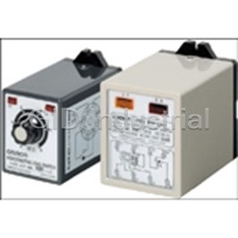
LED Displacement Sensor
Z4W-V25R
Part Number
Z4W-V25R
Price
Request Quote
Manufacturer
OMRON AUTOMATION
Lead Time
Request Quote
Category
Sensors and Transducers » Specialized Sensor
Specifications
Manufacturer
Omron Automation
Manufacturers Part #
Z4W-V25R
Industry Aliases
Z4W-V25R
Sub-Category
Specialized Sensors
Factory Pack Quantity
1
Datasheet

Extracted Text
LED Displacement Sensor Z4W-V Low-cost Displacement Sensor with 10-micron Resolution with Red LED ■ Measurement point: 25 mm; measurement range: 4 mm. ■ Easy adjustment, range/stable light indicators. ■ Easy-to-use built-in Amp. ■ High-speed response: 5 ms. ■ Visible beam spot. ■ Enclosure rating: IP66. Ordering Information Sensing distance Resolution Model 254 mm 10 m Z4W-V25R 5M 1 Z4W-V Z4W-V Specifications ■ Ratings Measurement range ±4 mm Measurement point 25±1 mm Light source Red LED Spot diameter 2-mm dia. (at measurement point) Resolution 10 microns (see Note. 1) Linearity ±3% FS (See Note. 2) Response time 5 ms (In case of white alumina ceramic. Linearity change according to object.) Temperature characteristics ±0.3% FS/°C Warming up time 3 min (within 1% of stable value) Indicators Stability: Stable range: Lit green Operating range: Not lit Dark: Lit red Range: In range: Green Out of range: Red Outputs Analog output: 4 to 20 mA/±4 mm Load impedance: 300Ω max. DARK output: NPN open collector 50 mA max., 30 VDC Residual voltage: 1 V max. External light 3,000 ln (incandescent light) ■ Characteristics Power supply voltage 12 to 24 VDC±10%: ripple (p-p) 10% max. Current consumption 80 mA max. Vibration resistance Destruction: 10 to 55 Hz (1.5-mm double amplitude) for 2 sweeps of 15 min each in X, Y, and Z directions 2 Shock resistance Destruction: 500 m/s for 3 times each in X, Y, and Z directions Ambient temperature Operating: –10° to 55°C (with no icing) Ambient humidity 35% to 85% (with no icing) Degree of protection IP66 Weight 150 g (with 5-m cable); 50 g (without cable) Attachments Mounting bracket, mounting screws, resistor (250Ω, 0.5 W) Note: 1. Resolution 2. Response Time The resolution is the peak-to-peak displacement The delays are the 10% to 90% rising and conversion value of the analog output. falling times of the analog output in response (Conditions: white alumina ceramic at the to a sudden change in the displacement. measurement point) Displacement Output fluctuation 90% 10% Analog displacement output Tr Ti Engineering Data (Reference Value) ■ Linearity Characteristics vs. Objects Linearity characteristic curves are obtained by detecting an object at different positions within the measurement range and plotting the analog output error resulting from each operation. The LED Displacement Sensor cannot detect an object accu- rately if the reflection ratio of the object is extremely small (a black object) or extremely large (an object with a glossy surface). 2 Z4W-V Z4W-V Inclined Object (Typical Example) Angle: 0° Angle: −15° Angle: +15° White ceramic White ceramic White ceramic Black paper Black paper Black paper Rolled steel Rolled steel Rolled steel plate plate plate Positive Positive inclination inclination Negative Negative inclination inclination Measurement point Measurement point Measurement point (distance in mm) (distance in mm) (distance in mm) Angle: −30° Angle: +30° White ceramic White ceramic Black paper Black paper Rolled steel Rolled steel plate plate Positive Positive inclination inclination Negative Negative inclination inclination Measurement point Measurement point (distance in mm) (distance in mm) Obliquely Positioned Object (Typical Example) Angle: −15° Angle: +15° White ceramic White ceramic Black paper Black paper Rolled steel Rolled steel plate plate Positive Positive inclination inclination Negative Negative inclination inclination Measurement point Measurement point (distance in mm) (distance in mm) Angle: −30° Angle: +30° White ceramic White ceramic Black paper Black paper Rolled steel Rolled steel plate plate Note: The LED Displacement Sen- sor cannot detect an object accurately if the object is positioned at an angle obli- que to the sensor position. If the oblique angle is large, detection is not possible be- cause of insufficient reflec- Positive Positive tion of light. This must be inclination inclination taken into consideration Negative Negative inclination when installing the sensor. inclination Measurement point Measurement point (distance in mm) (distance in mm) 3 Error (% FS) Error (% FS) Error (% FS) Error (% FS) Error (% FS) Error (% FS) Error (% FS) Error (% FS) Error (% FS) Z4W-V Z4W-V ■ Sensing Various Objects Offset Error vs. Object Material When detecting a variety of objects successively, refer to the off- set error graph below. The graph illustrates the change in sensor output characteristics when black paper is compared to white paper. To reduce the offset error value, install the Sensor so that objects are detected at or as close as possible to the measure- ment point. Offset Error Range (Typical Example) Measurement point (distance in mm) ■ Angle Characteristics The angle characteristics were obtained by detecting an object with different angles of inclination at the measurement point and plotting the analog output error resulting from each operation. The LED Displacement Sensor is designed to detect the front of an object facing the sensor. Error occurs when the object is posi- tioned at an oblique angle to the sensor. Inclined Object Obliquely Positioned Object (Typical Example) (Typical Example) White ceramic White ceramic Black paper Black paper Rolled steel Rolled steel plate plate Positive Positive inclination inclination Negative Negative inclination inclination Inclination angle (°) Inclination angle (°) 4 Offset Error (% FS) Error (% FS) Error (% FS) Z4W-V Z4W-V Nomenclature Range indicator (green/red) Stability indicator (green/red) Optical axis marker Transmitter Receiver Operation ■ Connections/Output Circuits Power supply (Brown) 12 to 24 VDC GND (Blue) 0 V DARK output (Orange) 50 mA max. at 30 VDC Analog output (Black) 40 to 20 mA GND (Shield)* Load power supply (30 VDC max.) (Red) 12 to 24 VDC (White) 4 to 20 mA (Orange) (Shield) Linear (Black) differentiator, etc. 0 V Note: *The two ground terminals (black and shield) are internally connected. However, the black ground must be used with the red terminal for the power supply and the shield ground must be used with the white terminal for the analog output. 5 Signal processor Z4W-V Z4W-V ■ Functions Classification Functions Remarks Range indicator When the intensity of the The green indicator is lit when the ob- Out of the Distance Red measurement range light input is insufficient ject is within the measurement range. 21 mm The red indicator is lit when the object (DARK output is ON and the is not within the measurement range. red stability indicator is lit), Inside the Green 25 mm the range indicator all remain measurement range OFF even if the object is 29 mm within the measurement Out of the Red range. measurement range Stability indica- These indicators indicate the intensity of the light input. The object in the measurement --- tor range is detected when the green indicator is lit or OFF. The red indicator is lit when there is no object in the measurement range or the inten- sity of light input is insufficient. If this green indicator is lit when there is an object in the measurement range, the light source control circuit and light input sensitivity control circuit of the Sensor operate. Even if the green indicator is OFF, the Sensor works as long as the internal light source control circuit and the light input sensitivity circuit are within the operating range. In this case the red indicator is also OFF. When the Sensor is active for a long duration, the green indicator may turn OFF. This does not mean that the Sensor has malfunctioned. DARK output The orange indicator (DARK output) is ON when there is no object in the measurement --- range or when the input light intensity is insufficient. The red stability indicator is also lit when DARK output is ON. The Sensor has an open collector output of 50 mA at 30 VDC max. Analog output --- An analog signal is output from the output Distance vs Analog Output Characteristics line (white) according to the sensing (Typical Example) distance. Output: 4 to 20 mA/21 to 29 mm (±4 mm) Load impedance: 300 W max.The output 20 range lies between 20.5 and 26 mA when DARK output is ON. 12 Measurement point 4 25±1 mm −4 0 4 Measurement point (distance in mm) ■ Operations Wiring Basic Operation of the Z4W-V25R Connect the Sensor to the controlling device using a sensor Mounting cable. Do not switch power ON during wiring. Refer to the instruc- Install the Sensor so that of the optical axis of the Sensor and the tions on the Sensor and the connection diagram (page 5) before surface of the object meet at right angles (i.e., the panel that connecting the sensor to the controlling device. incorporates the light source is parallel with the object). For accu- Conversion to Voltage Output Model (1 to 5 V) rate results, it is recommended that the sensing distance is set to the measurement point (25 mm). The Z4W-V25R has a current output of 4 to 20 mA. With the resistor provided (250 Ω), a voltage output of 1 to 5 V can be obtained. Refer to the figure below for connection. (Black) 4 to 20 mA 8.5 mm 70 mm from the sensor mounting 25 Resistor holes Check the Shield voltage here 0 V Surface from which the beam is emitted 25 mm Although a resistor is included, any resistor may be used provided Surface of object the resistance is 300 Ω or less. Note: Do not tighten the mounting screws for the moment as the optical axis must be adjusted. 6 Analog output (mA) Z4W-V Z4W-V Axis Adjustment Z4W-V25R Synchronization sensor When the Sensor power is switched ON, the red transmitter indi- cator is lit. Move the Sensor so that the red beam (see the figure below) focuses on the object. The entire light beam should be focused on the object or an error will result. 4 to 20 mA Black Surface 0 V of object 0 V Blue Correct Incorrect DARK output Orange 0 V Blue 4 to 20 mA +12 V Brown +12 V 0 V Output Black Spot 12 V Brown After the optical axis has been adjusted, tighten the mounting Z4W-DD1C screws firmly. 100 mA 30 VDC Connecting a Z4W-DD1C Linear Sensor Max. Controller To discriminate among objects according to size, use the Z4W- V25R LED Displacement Sensor with a Z4W-DD1C Linear Sen- sor Controller. 100 to 240 VAC FG 50/60Hz Tolerance Axis Adjustment After adjusting the optical axis of the LED Displacement Sensor, adjust the optical axis of the Synchronization Sensor so that the LED Displacement Sensor detects the object at the measurement Output ON position in synchronous operation. Since the Linear Sensor Con- PASS OFF Output troller operates synchronously on receiving each output signal of ON NG OFF the Synchronization Sensor, set the position of the Synchroniza- tion Sensor so that the front edge of the object is detected by the Synchronization Sensor. The following equipment is required: Z4W-V25R LED Displacement Sensor Z4W-DD1C Linear Sensor Controller Displacement Synchronization Sensor (E3X Fiber Photoelectric Sensor or sensor E3C-VM Miniature Head Photoelectric Sensor is recommended) An object of standard dimensions An object of threshold dimensions Synchronization Surface of sensor Tools object Mounting Mount as described on page 6. When installing a Synchronization Sensor, refer to the instruction manual and read the precautions for the model. It is important to install the Synchronization Sensor so that the LED Displacement After the optical axis has been adjusted, tighten the mounting Sensor can detect the object at the measurement position. Do not screws and secure the Synchronization Sensor firmly. Some Syn- tighten the mounting screws for the moment since the optical axis chronization Sensor models incorporate a sensitivity controller. must be adjusted. For the adjustment of such models, refer to the instruction manual The Z4W-DD1C Linear Sensor Controller can be mounted on a for the Synchronization Sensor. wall and secured with screws, or mounted to DIN rail. Wiring Make sure that the Linear Sensor Controller, the LED Displace- ment Sensor, and the Synchronization Sensor are wired correctly before turning on the Linear Sensor Controller power (power is supplied to the LED Displacement Sensor and the Linear Sensor Controller by the Linear Sensor Controller). To avoid trouble, leave the output terminals (No. 4, 5, 6) of the Linear Sensor Con- troller open for the moment. 7 Shield Z4W-V Z4W-V Adjustment and Operation of the Linear Sensor Controller Control panel of the Linear Sensor Controller The control panel consists of two switches (MODE and MONI- TOR), two adjusters (CENTER and WIDTH) and four indicators (POWER, PASS, NG, INHIBIT) for monitoring. By adjusting the settings of the Linear Sensor Controller and compensating for the position of the LED Displacement Sensor, the size of the object of standard dimensions is registered with the Linear Sensor Controller. With the object of standard dimen- sions, operate the LED Displacement Sensor as follows: 1. Set the MODE switch to NORMAL. 2. Turn the WIDTH adjuster counterclockwise to the MIN posi- tion. 3. Turn the CENTER adjuster clockwise or counterclockwise and set the adjuster to the position where the PASS indica- tor is lit. If the PASS indicator is lit for a wide range of posi- tions, set the adjuster in the middle of the range. If the PASS indicator does not light with the CENTER adjuster in any position, turn the WIDTH adjuster clockwise slightly. An object of threshold dimensions or a multimeter can be used to determine the tolerance (use the object where possible). Determining Settings Using an Object 1. Prepare an object of threshold dimensions (an object with the allowable upper threshold dimensions or with the allow- able lower threshold dimensions) to be detected by the LED Displacement Sensor. 2. Set the MODE switch to NORMAL. 3. Turn the WIDTH adjuster counterclockwise to the MIN posi- tion. The NG indicator will light. 4. Turn the WIDTH adjuster clockwise slowly to the position where the NG indicator turns OFF. The PASS indicator will light. Determining Settings Using a Multimeter Determine the absolute tolerance, A (in mm), and obtain the volt- age V (V) as follows (example for tolerance of ±0.5 mm): x 1. Set the MONITOR switch to WIDTH. 2. Check the voltage of monitor terminals 10 (positive voltage output) and 8 (negative voltage output) of the Linear Sensor Controller with the multimeter in the 10-VDC or 5-VDC range. 3. Turn the WIDTH adjuster clockwise or counterclockwise to the position where the voltage reaches V (obtained from x the above formula). Set the MODE switch to TRIG as follows: 1. Set the MODE switch to TRIG. 2. Set the MONITOR switch to INPUT or OFFSET (RUN). 3. Turn off the power and wire the output terminals (No. 4, 5, and 6). 8 Z4W-V Z4W-V Dimensions Cord length: 5 m 50 Cord: 3.8 dia. 5 28 20.3 Two, M4 Mounting Holes screws Two, 5 dia. holes 11.4 28 10.5 50 45 (8.5) (70) Emitting Emitting (25) axis axis 30° Emitting axis Measurement point Measurement point Measurement point 13.5 Measurement point 2.3 5.3 With Mounting Bracket 1 20.3 Mounting Holes 22 Two, M4 57.8 55.5 28 22.5 25 12 Two, M4 Two mounting 12 screws holes A* 11.4 4.5 R27 10.5 37 50 10.5 * A mounting bracket can be attached to this face of the sensor. 12.5 4.5 ** This distance can be extended up to 44.5 42.5** 5.5 mm. When this distance is 44.5 mm in 10 Emitting Emitting 42 axis length, the angle of the optical axis can be axis 32.3 adjusted after mounting by approximately 22.2 ±5 max. Measurement point Measurement point 9 Z4W-V Z4W-V With Mounting Bracket 2 37 4.5 20.3 22 28 13.5 to A* 18.5 to 17.5 22.5 11.4 Mounting Holes 10.5 63.5 to 67.5 Two, M4 25 holes 88.5 to 92.5 50 Emitting Emitting axis axis Measurement point Measurement point 34.8 17.5 5 32.5 10.5 * A mounting bracket can be attached 4.5 to this face of the sensor. 10 R27 12 22.2 32.3 5.3 19 Emitting axis 10 Z4W-V Z4W-V Installation ■ Controller Connections Z4W-DD1C Z4W-V25R Synchronization Connection with a S3A-DAK sensor Shield 0 V Z4W-V25R 4 to 20 mA Brown Blue Black 4 to 20 mA Black 80 mA 30 VDC Max 0 V 0 V IN 0 V Blue DARK output Orange +12±10% ERROR HI MID LOW 0 V 80 mA Max. HI MID LOW +12 V 0 V 4 to 20 mA Blue +12 V Brown Output Black S3A-DAK +12 V Brown 100/110 VAC 3A 250 VAC Max 50/60 Hz Z4W-DD1C 100 mA 200/220 VAC 50/60 Hz 30 VDC Max. 100 to 240 VAC FG 50/60 Hz Connection with a K3TX Press switch to calibrate to zero K3TS 17 10 1 9 Brown Black Z4W-V25R Blue Shielded cable LED Displacement Sensor Brown Black + Z4W-V25R 12 VDC − LED Displacement Blue Sensor Shielded cable 11 Shield Z4W-V Z4W-V Precautions Install the Sensor in a clean environment keep the filter (on the Environment front of the Sensor) free from oil and dust. If affected by oil or Refrain from using the LED Displacement Sensor in a strong dust, clean the Sensor as follows: electromagnetic field or in an environment where the operation of 1. Use a blower brush (used to clean camera lenses) to blow the Sensor is subject to the reflection of intensive light (such as a large dust particles from the surface. Do not blow the dust laser beam or an electric arc welding machine). away with your mouth. The LED Displacement Sensor cannot accurately detect a mirror- 2. Use a soft cloth (for lenses) with a little alcohol to remove like object, a transparent object, one with an extremely small the remaining dust. reflection ratio, an object smaller than the diameter of the Sen- Do not use a scrubbing action when cleaning as a scratch sor’s sensing spot, or an inclined object. on the filter could result in the Sensor malfunctioning. Wiring Interference The power supply cable for the Z4W-V25R should not be wired Z4W-V25R LED Displacement Sensors can be installed within with high-voltage lines or power lines in order to avoid interfer- close proximity to each other and operate independently without ence, damage, or malfunction. interference (refer to the figures below). However, if they are installed at an oblique angle to each other, interference may Others result. The Sensor cannot detect an object accurately if the surface of the object consists of different materials placed next to each other (refer to the figures below). In such case install the Sensor so that the boundaries of the materials and the Sensor are parallel. When using the LED Displacement Sensor in combination with another type of Sensor (such as a Photoelectric Sensor), the sen- sor beams should be as close to perpendicular as possible. ALL DIMENSIONS SHOWN ARE IN MILLIMETERS. To convert millimeters into inches, multiply by 0.03937. To convert grams into ounces, multiply by 0.03527. CSM_3_1_0315 E217-E1-03 In the interest of product improvement, specifications are subject to change without notice. OMRON Corporation Industrial Automation Company Sensing Devices Division H.Q. Application Sensors Division Shiokoji Horikawa, Shimogyo-ku, Kyoto, 600-8530 Japan Tel: (81)75-344-7068/Fax: (81)75-344-7107
Frequently asked questions
How does Electronics Finder differ from its competitors?

Is there a warranty for the Z4W-V25R?
Which carrier will Electronics Finder use to ship my parts?
Can I buy parts from Electronics Finder if I am outside the USA?
Which payment methods does Electronics Finder accept?
Why buy from GID?

Quality
We are industry veterans who take pride in our work

Protection
Avoid the dangers of risky trading in the gray market

Access
Our network of suppliers is ready and at your disposal

Savings
Maintain legacy systems to prevent costly downtime

Speed
Time is of the essence, and we are respectful of yours
Related Products
Floatless Level Switch 8-Pin 61F-HSLAC100
Floatless Level Switch 8-Pin 61F-HSLAC110
Floatless Level Switch 8-Pin 61F-HSLAC115
Floatless Level Switch 8-Pin 61F-HSLAC220
Floatless Level Switch 8-Pin 61F-HSLAC24
Floatless Level Switch 8-Pin 61F-UHSAC100
Request a Quote

The quote request has been received
Close

Facing challenges or have inquiries? Feel free to contact us!
Call Us +1-469-283-2440
What they say about us
FANTASTIC RESOURCE
One of our top priorities is maintaining our business with precision, and we are constantly looking for affiliates that can help us achieve our goal. With the aid of GID Industrial, our obsolete product management has never been more efficient. They have been a great resource to our company, and have quickly become a go-to supplier on our list!
Bucher Emhart Glass
EXCELLENT SERVICE
With our strict fundamentals and high expectations, we were surprised when we came across GID Industrial and their competitive pricing. When we approached them with our issue, they were incredibly confident in being able to provide us with a seamless solution at the best price for us. GID Industrial quickly understood our needs and provided us with excellent service, as well as fully tested product to ensure what we received would be the right fit for our company.
Fuji
HARD TO FIND A BETTER PROVIDER
Our company provides services to aid in the manufacture of technological products, such as semiconductors and flat panel displays, and often searching for distributors of obsolete product we require can waste time and money. Finding GID Industrial proved to be a great asset to our company, with cost effective solutions and superior knowledge on all of their materials, it’d be hard to find a better provider of obsolete or hard to find products.
Applied Materials
CONSISTENTLY DELIVERS QUALITY SOLUTIONS
Over the years, the equipment used in our company becomes discontinued, but they’re still of great use to us and our customers. Once these products are no longer available through the manufacturer, finding a reliable, quick supplier is a necessity, and luckily for us, GID Industrial has provided the most trustworthy, quality solutions to our obsolete component needs.
Nidec Vamco
TERRIFIC RESOURCE
This company has been a terrific help to us (I work for Trican Well Service) in sourcing the Micron Ram Memory we needed for our Siemens computers. Great service! And great pricing! I know when the product is shipping and when it will arrive, all the way through the ordering process.
Trican Well Service
GO TO SOURCE
When I can't find an obsolete part, I first call GID and they'll come up with my parts every time. Great customer service and follow up as well. Scott emails me from time to time to touch base and see if we're having trouble finding something.....which is often with our 25 yr old equipment.
ConAgra Foods