

 Manufacturers
OMRON ELECTRONIC COMPONENTS A3A-211
Description
Switch Access Push Button Switch Flange
A3A-211
Part Number
A3A-211
Price
Request Quote
Manufacturer
OMRON ELECTRONIC COMPONENTS
Lead Time
Request Quote
Category
Sensors and Transducers » Switch Accessories
Specifications
Manufacturer
Omron Electronic Components
Manufacturers Part #
A3A-211
Industry Aliases
A3A-211
Sub-Categories
Switch Accessories
Factory Pack Quantity
10
Datasheet

Extracted Text
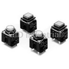
A3A
Lighted Pushbutton Switch
Compact High-capacity
Push-button Switch
●Ideal for use as a high breaking capacity Power
Switch.
●Switches from micro load (minimum applicable load:
5 VDC 1mA) to high capacity load.
RoHS Compliant
A
Refer to Safety Precautions for All Pushbutton Switches and
3
Safety Precautions on page 8.
A
List of Models
●Non-lighted Push-button Switches ●Lighted Push-button Switches
Appearance Model Illumination Appearance Model
A3AA-9@ A3AA-9@
Square Square
@1-00@ @1-00E@
LED
surface
illumination
A3AT-9@ A3AT-9@
Round Round
@1-00@ @1-00E@
Model Number Structure
The model numbers used to order sets of Units are illustrated below.
■Model Number Legend (Ordering as a Set)......
One set comprises the Pushbutton (LED lamp built-in) and Switch.
For information on combinations, refer to Ordering Information.
(1) (2) (3) (4) (5)
A3A A -9 0K 1- 00E R
(1) Shape of Pushbutton
(5) Color
Symbol Shape 1. Pushbutton
A Square
(Non-lighted Models)
T Round
Symbol Color
L Light gray
(2) Terminal
RRed*
Symbol Type Y Yellow*
0 Solder
G Green*
1PCB ABlue
BBlack
DDark gray
(3) Switch Specifications
HGray
Symbol Operation Contact type
2. LED (Surface
A Momentary
(4) Illumination
3 A at 125 VAC,
SPDT Illumination Models)
( )
2 A at 30 VDC
B Alternate
Symbol Operation
Symbol Color
6 A at 125 VAC,
K Momentary
00 Non-lighted
RRed
SPST-NO 2 A at 250 VAC,
( )
00E Surface illumination
L Alternate
4 A at 30 VDC
Y Yellow
GGreen
* Common to both lighted and
non-lighted models.
■Specifications: Refer to page 3. ■Dimensions: Refer to page 5.
■Accessories: Refer to page 2.
1
A3A Lighted Pushbutton Switch
List of Models
SPST-NO
Color symbol for Minimum
Appearance Terminal Operation Illumination Model
pushbutton packing unit
Square/A3AA
Non-lighted A3AA-90K1-00@
Momentary
LED surface illumination A3AA-90K1-00E@
Solder
Non-lighted A3AA-90L1-00@
Alternate
LED surface illumination A3AA-90L1-00E@
(Non-lighted)
Non-lighted A3AA-91K1-00@
R (red)
Momentary
Y (yellow)
LED surface illumination A3AA-91K1-00E@
PCB G (green)
Non-lighted A3AA-91L1-00@
L (light gray)
Alternate
A (blue)
LED surface illumination A3AA-91L1-00E@
B (black) 100
Round/A3AT
Non-lighted A3AT-90K1-00@
D (dark gray)
A Momentary
H (gray)
LED surface illumination A3AT-90K1-00E@
3
(Surface illumination)
Solder
A
Non-lighted A3AT-90L1-00@
R (red)
Alternate
Y (yellow)
LED surface illumination A3AT-90L1-00E@
G (green)
Non-lighted A3AT-91K1-00@
Momentary
LED surface illumination A3AT-91K1-00E@
PCB
Non-lighted A3AT-91L1-00@
Alternate
LED surface illumination A3AT-91L1-00E@
Note: The above models each have a SPST-NO contact that can switch 6 A at 125 VAC, 2 A at 250 VAC, and 4 A at 30 VDC. When ordering any of the above models,
replace @ of the model number with a code to indicate the pushbutton color of the model (i.e., replace @ with R, Y, G, L, A, B, D, H, and L). The pushbutton of
an A3A does not illuminate if the color of the pushbutton is dark gray, gray, light gray, blue, or black.
SPDT
Color symbol for Minimum
Appearance Terminal Operation Illumination Model
pushbutton packing unit
Square/A3AA
Non-lighted A3AA-90A1-00@
Momentary
LED surface illumination A3AA-90A1-00E@
Solder
Non-lighted A3AA-90B1-00@
Alternate
LED surface illumination A3AA-90B1-00E@
(Non-lighted)
Non-lighted A3AA-91A1-00@
R (red)
Momentary
Y (yellow)
LED surface illumination A3AA-91A1-00E@
PCB G (green)
Non-lighted A3AA-91B1-00@
L (light gray)
Alternate
A (blue)
LED surface illumination A3AA-91B1-00E@
B (black) 100
Round/A3AT
Non-lighted A3AT-90A1-00@
D (dark gray)
Momentary
H (gray)
LED surface illumination A3AT-90A1-00E@
(Surface illumination)
Solder
Non-lighted A3AT-90B1-00@
R (red)
Alternate
Y (yellow)
LED surface illumination A3AT-90B1-00E@
G (green)
Non-lighted A3AT-91A1-00@
Momentary
LED surface illumination A3AT-91A1-00E@
PCB
Non-lighted A3AT-91B1-00@
Alternate
LED surface illumination A3AT-91B1-00E@
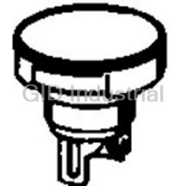
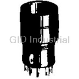
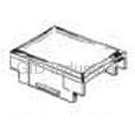
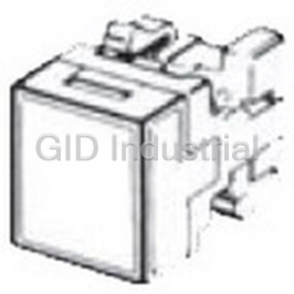
■Accessories
Flange (Select according to panel color.)
Minimum
Name Shape Classification Model
packing unit
Black A3A-241
Square
@12.7
Light gray A3A-242
Flange alone
Black A3A-251
Round
φ12.7
Light gray A3A-252
Flange Leaf spring A3A-200 100
Black A3A-211
Square
@12.7 Flange and leaf
Light gray A3A-212
spring
Black A3A-221
Round (one each)
φ12.7
Light gray A3A-222
Note: An A3A with solder terminals is provided with a round or square black flange and leaf spring. A round black flange is provided with each A3A having solder
terminals and a round pushbutton. A square black flange is provided with each A3A having solder terminals and a square pushbutton.
2
A3A Lighted Pushbutton Switch
Specifications
■Approved Standards ■Characteristics
Momentary action: 120 operations/minute max.
• SPST-NO SPDT
Mechanical
Operating
Alternate action: 60 operations/minute max. *1
6 A at 125 VAC 3 A at 125 VAC frequency
UL
Electrical 20 operations/minute max.
2 A at 250 VAC 2 A at 30 VDC
CSA
Insulation resistance 100 MΩ min. (at 500 VDC)
4 A at 30 VDC
Contact resistance 100 mΩ max. (initial value)
Between
■Ratings
terminals of 600 VAC, 50/60 Hz for 1 min
same polarity
Dielectric
Item
AC resistive load DC resistive load
strength
Between
Type Contact form
each terminal 2,000 VAC, 50/60 Hz for 1 min
6 A at 125 VAC
and ground
General load SPST-NO 4 A at 30 VDC
2 A at 250 VAC
Vibration
Malfunction 10 to 55 Hz, 1.5-mm double amplitude *2
Note: Minimum allowable load: 5 VDC 1 mA (Resistive)
resistance
A
The ratings given above are for testing under the following conditions:
2 3
Destruction 500 m/s
(1) Ambient temperature: 20 ±2°C
Shock
A
(2) Ambient humidity: 65 ±5% resistance 2
Malfunction 150 m/s *2
(3) Operating frequency: 20 times/minute
Momentary action: 1,000,000 operations min.
Mechanical
LED
Alternate action: 50,000 operations min. *1
Durability
Illumination Surface illumination Electrical 50,000 operations min.
Item Red Yellow Green Weight Approx. 3.2 g
Standard value (V) * Ambient operating
2.0 2.1 2.1 −10°C to +55°C (with no icing)
(IF = 10 mA) temperature
Forward voltage VF
Maximum value (V) 3.0 Ambient operating humidity 35% to 85%
Forward current IF Maximum value (mA) 20 20 25 Ambient storage
−25°C to +65°C (with no icing)
temperature
Permissible loss PD Maximum value (mW) 60 60 75
Degree of protection IP00
Reverse voltage VR Maximum value (V) 3
Electric shock protection
Note: The above built-in LEDs do not have a resistor. Connect to each of the Class II
class
above built-in LEDs a resistor that satisfies the above conditions.
* Refer to the VF – IF characteristic graphs on page 8. PTI (proof tracking index) 175
Pollution degree 3 (IEC947-5-1)
■Operating Characteristics
*1. With alternate operation models, one operation cycle consists of set and
reset operations.
Operating force OF max. 2.45 N
*2. Indicates malfunctions of less than 1 ms.
Release force RF min. 0.15 N
■Contact Form
Total travel TT Approx. 2mm
Contact name Contact form Contact type
Pretravel PT max. 1.5 mm
Double-break SPST-NO
Locktravel alternate * LTA min. 0.5 mm NO NO
* Alternate operation models only. NC
Double-throw SPDT
COM NO
3
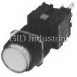
A3A Lighted Pushbutton Switch
Nomenclature
■Model Structure
Frequently asked questions
How does Electronics Finder differ from its competitors?

Is there a warranty for the A3A-211?
Which carrier will Electronics Finder use to ship my parts?
Can I buy parts from Electronics Finder if I am outside the USA?
Which payment methods does Electronics Finder accept?
Why buy from GID?

Quality
We are industry veterans who take pride in our work

Protection
Avoid the dangers of risky trading in the gray market

Access
Our network of suppliers is ready and at your disposal

Savings
Maintain legacy systems to prevent costly downtime

Speed
Time is of the essence, and we are respectful of yours
Related Products
Switch Access Push Button Switch Push Button Unit A3BT-500Y

Switch Access Push Button Switch Round Button A3BT-510W
Switch Access Push Button Switch Switch Unit A3BT-7011-1
Switch Access Push Button Switch Round Case A3GT-6021-1
Switch Access Push Button Switch Rectangular Cap A3PJ-5600-A
Switch Access Push Button Switch Square Screen A3SA-5801
Request a Quote

The quote request has been received
Close

Facing challenges or have inquiries? Feel free to contact us!
Call Us +1-469-283-2440
What they say about us
FANTASTIC RESOURCE
One of our top priorities is maintaining our business with precision, and we are constantly looking for affiliates that can help us achieve our goal. With the aid of GID Industrial, our obsolete product management has never been more efficient. They have been a great resource to our company, and have quickly become a go-to supplier on our list!
Bucher Emhart Glass
EXCELLENT SERVICE
With our strict fundamentals and high expectations, we were surprised when we came across GID Industrial and their competitive pricing. When we approached them with our issue, they were incredibly confident in being able to provide us with a seamless solution at the best price for us. GID Industrial quickly understood our needs and provided us with excellent service, as well as fully tested product to ensure what we received would be the right fit for our company.
Fuji
HARD TO FIND A BETTER PROVIDER
Our company provides services to aid in the manufacture of technological products, such as semiconductors and flat panel displays, and often searching for distributors of obsolete product we require can waste time and money. Finding GID Industrial proved to be a great asset to our company, with cost effective solutions and superior knowledge on all of their materials, it’d be hard to find a better provider of obsolete or hard to find products.
Applied Materials
CONSISTENTLY DELIVERS QUALITY SOLUTIONS
Over the years, the equipment used in our company becomes discontinued, but they’re still of great use to us and our customers. Once these products are no longer available through the manufacturer, finding a reliable, quick supplier is a necessity, and luckily for us, GID Industrial has provided the most trustworthy, quality solutions to our obsolete component needs.
Nidec Vamco
TERRIFIC RESOURCE
This company has been a terrific help to us (I work for Trican Well Service) in sourcing the Micron Ram Memory we needed for our Siemens computers. Great service! And great pricing! I know when the product is shipping and when it will arrive, all the way through the ordering process.
Trican Well Service
GO TO SOURCE
When I can't find an obsolete part, I first call GID and they'll come up with my parts every time. Great customer service and follow up as well. Scott emails me from time to time to touch base and see if we're having trouble finding something.....which is often with our 25 yr old equipment.
ConAgra Foods