

 Manufacturers
OMRON ELECTRONIC COMPONENTS A3SA-5801
Description
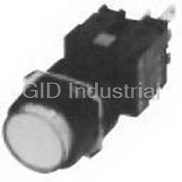
Switch Access Push Button Switch Square Screen
A3SA-5801
Part Number
A3SA-5801
Price
Request Quote
Manufacturer
OMRON ELECTRONIC COMPONENTS
Lead Time
Request Quote
Category
Sensors and Transducers » Switch Accessories
Specifications
Manufacturer
Omron Electronic Components
Manufacturers Part #
A3SA-5801
Industry Aliases
A3SA-5801
Sub-Categories
Switch Accessories
Factory Pack Quantity
10
Datasheet

Extracted Text
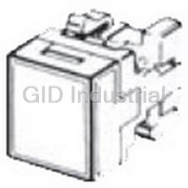
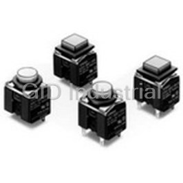
Lighted Pushbutton Switch (Square) A3S CSM_A3S_DS_E_7_1 Pushbutton Switch Series with Square 40-mm Body • Combines miniature design with distinct but soft sense of operation. • Easy panel mounting from the front and simple lamp replacement without tools. Refer to Safety Precautions for All Pushbutton Switches/ Indicators and Safety Precautions on page 18. List of Models Lighted Pushbutton Switches Appearance Model Rectangular A3SJ Square A3SA ■ Specifications: Refer to page 12. ■ Dimensions: Refer to page 14. ■ Accessories: Refer to pages 10 to 11. 1 A3S Model Number Structure Model Number Legend ..... The model numbers used to order sets are illustrated below. One set comprises the Operation Unit, Lamp, and Socket Unit. For information on combinations, refer to Ordering Information on pages 3 to 4. 1 - 24E R ............ Single screen (1) (2) Left Right A 3 S J - 9 0 A 3 - 24E RW ............ Vertical 2-split screen Left Right R W (Red) (White) (1) Shape of (2) Switch Specifications (3) Screen Pattern (4) Lighting Method (5) Operation Unit Color For LED Operation Unit Standard Load Illumination-only models LED-lighted Models Sym- Symbol Operation Symbol Screen pattern Rated Symbol Color Shape Symbol bol voltage Single screen RRed A Momentary SPDT Rectan- 05E 5 VDC YYellow B Alternate J 1 gular 12E 12 VDC G Green C Momentary DPDT A Square 24E 24 VDC W White * D Alternate Vertical 2-split screen Incandescent Incandescent Microload Lamp-lighted Models Lamp-lighted Models 3 Symbol Operation Rated E Momentary Symbol Color Symbol SPDT (rectangular models only) voltage RRed F Alternate Models with colored illumination 06 6 VAC/VDC G Momentary YYellow can be ordered individually. Refer DPDT 14 14 VAC/VDC H Alternate to page 5 for details. G Green 28 28 VAC/VDC ABlue Standard Load Colored Illumination 250 VAC, 2 A W White * Unlit Lit 125 VDC, 0.4 A * The color cap is transparent. Microload White Color 125 VAC, 0.1 A 30 VDC, 0.1 A The built-in LED is colored. Minimum applicable load 5 VDC, 1 mA Number of Built-in LEDs and Incandescent Lamps Momentary operation Model Screen pattern LED Incandescent lamp ...Self-resetting Single screen 2 1 Alternate operation A3SJ Vertical 2-split ...Self-holding 22 screen A3SA Single screen 1 1 Type Structure of Split-screen Operation Unit Color cap Legend plate * Dispersion plate Light-separation plate (2-split screen only) Single screen Vertical 2-split screen LED/incandescent (Rectangular models (Rectangular models only) lamp holder and square models) A3SJ * Not included for the Square Models (A3SA) with incandescent lamp. 2 A3S Ordering Information Ordering as a Set .................The model numbers used to order sets of Units are given in the following tables. One set comprises the Operation Unit, Lamp, and Socket Unit. Standard Loads Rectangular Models Single Vertical 2-split 1 1 2 screen screen A3SJ Single screen Contact type Standard load (250 VAC, 2 A; 125 VDC 0.4 A) Operation Unit Operation Momentary operation Alternate operation color symbol (Self-resetting) (Self-holding) Output Lighting 5 VDC A3SJ-90A1-05E@ A3SJ-90B1-05E@ LED 12 VDC A3SJ-90A1-12E@ A3SJ-90B1-12E@ 24 VDC A3SJ-90A1-24E@ A3SJ-90B1-24E@ SPDT Enter the desired color 6 VAC/VDC A3SJ-90A1-06@ A3SJ-90B1-06@ symbol for the Pushbutton Incandescent 14 VAC/VDC A3SJ-90A1-14@ A3SJ-90B1-14@ in @. lamp 28 VAC/VDC A3SJ-90A1-28@ A3SJ-90B1-28@ R (Red) Y (Yellow) 5 VDC A3SJ-90C1-05E@ A3SJ-90D1-05E@ G (Green) LED 12 VDC A3SJ-90C1-12E@ A3SJ-90D1-12E@ A (Blue) * 24 VDC A3SJ-90C1-24E@ A3SJ-90D1-24E@ DPDT W (White) 6 VAC/VDC A3SJ-90C1-06@ A3SJ-90D1-06@ Incandescent 14 VAC/VDC A3SJ-90C1-14@ A3SJ-90D1-14@ lamp 28 VAC/VDC A3SJ-90C1-28@ A3SJ-90D1-28@ * Incandescent lamp only. Vertical 2-split screen Contact type Standard load (250 VAC, 2 A; 125 VDC 0.4 A) Operation Unit Operation Momentary operation Alternate operation color symbol (Self-resetting) (Self-holding) Output Lighting LED 24 VDC A3SJ-90A3-24E@@ A3SJ-90B3-24E@@ Enter the desired color symbol for the Pushbutton SPDT Incandescent in @@. 28 VDC A3SJ-90A3-28@@ A3SJ-90B3-28@@ lamp R (Red) Y (Yellow) LED 24 VDC A3SJ-90C3-24E@@ A3SJ-90D3-24E@@ G (Green) DPDT W (White) Incandescent A (Blue) * 28 VDC A3SJ-90C3-28@@ A3SJ-90D3-28@@ lamp * Incandescent lamp only. Microloads Single screen Vertical 2-split screen Contact type Microload Contact type Microload Operation Operation (125 VAC, 0.1 A; 30 VDC 0.1 A) (125 VAC, 0.1 A; 30 VDC 0.1 A) Unit color Unit color Operation Operation Momentary operation Momentary operation symbol symbol (Self-resetting) (Self-resetting) Output Lighting Output Lighting 5 VDC A3SJ-90E1-05E@ Enter the LED 24 VDC A3SJ-90E3-24E@@ LED 12 VDC A3SJ-90E1-12E@ Enter the desired col- 24 VDC A3SJ-90E1-24E@ desired col- SPDT or symbol SPDT Incan- or symbol 6 VAC/VDC A3SJ-90E1-06@ Incan- for the 28 VDC A3SJ-90E3-28@@ descent for the descent 14 VAC/VDC A3SJ-90E1-14@ Pushbutton lamp Pushbutton lamp in @@. 28 VAC/VDC A3SJ-90E1-28@ in @. R (Red) 5 VDC A3SJ-90G1-05E@ LED 24 VDC A3SJ-90G3-24E@@ R (Red) Y (Yellow) LED 12 VDC A3SJ-90G1-12E@ Y (Yellow) G (Green) DPDT 24 VDC A3SJ-90G1-24E@ G (Green) Incan- W (White) DPDT A (Blue) * descent 28 VDC A3SJ-90G3-28@@ 6 VAC/VDC A3SJ-90G1-06@ Incan- A (Blue) * W (White) lamp descent 14 VAC/VDC A3SJ-90G1-14@ lamp * Incandescent lamp only. 28 VAC/VDC A3SJ-90G1-28 @ Individual models: Refer to pages 6 to 9. ■ Specifications: Refer to page 12. ■ Dimensions: Refer to page 14. (The Pushbutton, Lamp, and Switch can be ordered separately.) ■ Accessories: Refer to pages 10 to 11. 3 A3S Ordering Information Ordering as a Set ................. The model numbers used to order sets of Units are given in the following tables. One set comprises the Operation Unit, Lamp, and Socket Unit. Standard Loads Square Models Single screen A3SA Single screen Contact type Standard load (250 VAC, 2 A; 125 VDC 0.4 A) Operation Unit Operation Momentary operation Alternate operation color symbol (Self-resetting) (Self-holding) Output Lighting 5 VDC A3SA-90A1-05E@ A3SA-90B1-05E@ LED 12 VDC A3SA-90A1-12E@ A3SA-90B1-12E@ 24 VDC A3SA-90A1-24E@ A3SA-90B1-24E@ SPDT Enter the desired color 6 VAC/VDC A3SA-90A1-06@ A3SA-90B1-06@ symbol for the Pushbutton Incandescent 14 VAC/VDC A3SA-90A1-14@ A3SA-90B1-14@ in @. lamp 28 VAC/VDC A3SA-90A1-28@ A3SA-90B1-28@ R (Red) Y (Yellow) 5 VDC A3SA-90C1-05E@ A3SA-90D1-05E@ G (Green) LED 12 VDC A3SA-90C1-12E@ A3SA-90D1-12E@ A (Blue) * 24 VDC A3SA-90C1-24E@ A3SA-90D1-24E@ W (White) DPDT 6 VAC/VDC A3SA-90C1-06@ A3SA-90D1-06@ Incandescent 14 VAC/VDC A3SA-90C1-14@ A3SA-90D1-14@ lamp 28 VAC/VDC A3SA-90C1-28@ A3SA-90D1-28@ * Incandescent lamp only. Microloads Single screen Contact type Microload (125 VAC, 0.1 A; 30 VDC 0.1 A) Operation Unit color symbol Operation Momentary operation Output Lighting (Self-resetting) 5 VDC A3SA-90E1-05E@ LED 12 VDC A3SA-90E1-12E@ 24 VDC A3SA-90E1-24E@ SPDT Enter the desired color 6 VAC/VDC A3SA-90E1-06@ symbol for the Pushbutton Incandescent 14 VAC/VDC A3SA-90E1-14@ in @. lamp 28 VAC/VDC A3SA-90E1-28@ R (Red) Y (Yellow) 5 VDC A3SA-90G1-05E@ G (Green) LED 12 VDC A3SA-90G1-12E@ A (Blue) * 24 VDC A3SA-90G1-24E@ W (White) DPDT 6 VAC/VDC A3SA-90G1-06@ Incandescent 14 VAC/VDC A3SA-90G1-14@ lamp 28 VAC/VDC A3SA-90G1-28@ * Incandescent lamp only. Individual models: Refer to pages 6 to 9. ■ Specifications: Refer to page 12. ■ Dimensions: Refer to page 14. ■ Accessories: Refer to pages 10 to 11. (The Pushbutton, Lamp, and Switch can be ordered separately.) 4 A3S Ordering Information Illumination-only and Colored-illumination LED Models Illumination only describes LED models for which the screen color is the same whether the LED is lit or not. The screen simply becomes brighter when the LED lights. Example: Red LED Color cap (red) Not lit Red Legend plate (transparent) Display Lit Dispersion plate (milk-white) Red LED lamp holder LED (red) Colored illumination describes LED models for which the screen color is white when the LED is not lit and changes to the color of the LED lamp when the LED is lit. Example: Red LED Color cap (transparent) Not lit White Legend plate (transparent) Pushbutton Lit Dispersion plate (milk-white) Red LED lamp holder LED (red) Ordering .......................................With colored-illumination models, order the Display (Operation Unit), Lamp, and Socket Unit as shown in the following table. Display (Operation Unit) LED Socket Unit Rectangular Single screen A3SJ-5801 models Square models A3SA-5801 Select the LED lamps to suit your desired Select from the Switches on coloration from the selection on page 9. page 9. 2-split screen Rectangular A3SJ-5921 models only 5 A3S Ordering Information Ordering Individually......... Operation Units, Lamps, and Socket Units can be ordered separately. Combinations that are not available as sets can be created using individual Units. Also, store the parts as spares for maintenance and repairs. Ordering ....................................... Specify a model number from the following page. LED-lighted Models Incandescent Lamp-lighted Models Operation Unit Operation Unit Lamp (LED) Lamp (Incandescent Lamp) · DC-only · Standard lamp SLL-@@E@ SLL-@@ Socket Unit Socket Unit ■ Specifications: Refer to page 12. ■ Dimensions: Refer to page 14. Ordering set combinations: Refer to pages 3 to 4. ■ Accessories: Refer to pages 10 to 11. 6 A3S Ordering Information Ordering Individually .........Operation Units, Lamps, and Socket Units can be ordered separately. Combinations that are not available as sets can be created using individual Units. Also, store the parts as spares for maintenance and repairs. Operation Unit LED-lighted Models (LED is not built in.) Appearance Rectangular Models Square Models (2 LEDs) (1 LED) (transparent legend (transparent legend Screen pattern Display color plate built in) plate built in) White A3SJ-5801 A3SA-5801 Red A3SJ-5802 A3SA-5802 Single screen Green A3SJ-5803 A3SA-5803 Yellow A3SJ-5805 A3SA-5805 White/red A3SJ-5901 White/green A3SJ-5902 Standard White/yellow A3SJ-5904 split − Red/green A3SJ-5905 screen Red/yellow A3SJ-5907 Green/yellow A3SJ-5909 Red/white A3SJ-5911 Green/white A3SJ-5912 2-split Reverse screen * Yellow/white A3SJ-5914 split − Green/red A3SJ-5915 screen Yellow/red A3SJ-5917 Yellow/green A3SJ-5919 White/white A3SJ-5921 One-color Red/red A3SJ-5922 2-split − Green/green A3SJ-5923 screen Yellow/yellow A3SJ-5925 Note: The color cap is transparent when the display color is white. * Two-split screen configurations are given with the OMRON surface of the case downward. ■ Specifications: Refer to page 12. ■ Dimensions: Refer to page 14. Ordering set combinations: Refer to pages 3 to 4. ■ Accessories: Refer to pages 10 to 11. 7 A3S Ordering Information Ordering Individually......... Operation Units, Lamps, and Socket Units can be ordered separately. Combinations that are not available as sets can be created using individual Units. Also, store the parts as spares for maintenance and repairs. Operation Unit Incandescent Lamp-lighted Models (Incandescent lamp is not built in.) Appearance Rectangular Square (transparent legend (Legend plate not Screen pattern Display color plate built in) included) One lamp White A3SJ-5301 A3SA-5301 Red A3SJ-5302 A3SA-5302 Green A3SJ-5303 A3SA-5303 Blue A3SJ-5304 A3SA-5304 Yellow A3SJ-5305 A3SA-5305 Single screen Two lamps White A3SJ-5321 Red A3SJ-5322 Green A3SJ-5323 − Blue A3SJ-5324 Yellow A3SJ-5325 White/red A3SJ-5201 White/green A3SJ-5202 White/blue A3SJ-5203 White/yellow A3SJ-5204 Standard Red/green A3SJ-5205 split − Red/blue A3SJ-5206 screen Red/yellow A3SJ-5207 Green/blue A3SJ-5208 Green/yellow A3SJ-5209 Blue/yellow A3SJ-5210 Red/white A3SJ-5211 Green/white A3SJ-5212 2-split Blue/white A3SJ-5213 screen * Yellow/white A3SJ-5214 Reverse Green/red A3SJ-5215 split − Blue/red A3SJ-5216 screen Yellow/red A3SJ-5217 Blue/green A3SJ-5218 Yellow/green A3SJ-5219 Yellow/blue A3SJ-5220 White/white A3SJ-5221 Red/red A3SJ-5222 One-color 2-split Green/green A3SJ-5223 − screen Blue/blue A3SJ-5224 Yellow/yellow A3SJ-5225 Note: The color cap is transparent when the display color is white. * Two-split screen configurations are given with the OMRON surface of the case downward. ■ Specifications: Refer to page 12. ■ Dimensions: Refer to page 14. Ordering set combinations: Refer to pages 3 to 4. ■ Accessories: Refer to pages 10 to 11. 8 A3S Ordering Information Ordering Individually .........Operation Units, Lamps, and Socket Units can be ordered separately. Combinations that are not available as sets can be created using individual Units. Also, store the parts as spares for maintenance and repairs. Lamp LED Lamp Operating 5 VDC 12 VDC 24 VDC voltage Color Model (DC only) Model (DC only) Model (DC only) Red SLL-05ER SLL-12ER SLL-24ER Yellow SLL-05EY SLL-12EY SLL-24EY Green SLL-05EG SLL-12EG SLL-24EG White SLL-05EW SLL-12EW SLL-24EW Note: The A3SJ (M2SJ) requires two LEDs for each Switch. The A3SA (M2SA) requires one LED. Incandescent Lamp Lamp type Standard lamp Low-voltage lamp Operating voltage 5 VAC/VDC SLL-06 SLL-06H 12 VAC/VDC SLL-14 SLL-14H 24 VAC/VDC SLL-28 SLL-28H Note: The low-voltage lamp has an advantage in that it generates less heat. Switch (common to both LED models and incandescent lamp-lighted models) Rectan- Appearance Square gular Selection precautions models Number models of Contact type outputs Operation Momentary operation A3SJ-8010 A3SA-7010 Use the Socket Unit in 1 combination with the same Stan- Alternate operation A3SJ-8020 A3SA-7020 Silver shape Operation Unit dard contacts (rectangular or square). Momentary operation A3SJ-8030 A3SA-7030 load Example: 2 For the A3SJ-5801 Rectan- Alternate operation A3SJ-8040 A3SA-7040 gular Operation Unit, select Momentary operation A3SJ-8050 A3SA-7050 the A3SJ-8@@0 1 Socket Unit. Gold Alternate operation A3SJ-8060 A3SA-7060 Micro- Momentary operation is alloy load self-resetting, and alternate Momentary operation A3SJ-8070 A3SA-7070 contacts operation is self-holding (i.e., 2 Alternate operation A3SJ-8080 A3SA-7080 push-on, push-off). 9 A3S Ordering Information Accessories, Replacements, and Tools Accessories for Rectangular Models Name Appearance Classification Model Application precautions Short edge Barriers (1 pair) A3SA-4001 The purpose of a Barrier is to prevent malfunctioning and to improve design image of the mounting panel. Short intermediate Barriers A3SA-4002 There is one intermediate Barrier and one pair of Barrier edge Barriers (2 Barriers). Long edge Barriers (1 pair) A3SJ-4003 Mount Short Barriers horizontally. Mount Long Barriers vertically. Long intermediate Barriers A3SJ-4004 Switch Guard − A3SJ-5050 Cannot be used with Barrier or Seal Cover. Cannot be used with Barrier or Switch Guard. Seal Cover − A3SJ-5060 Cap material: Vinyl chloride Use when vertically mounting individual (with Barrier) Long or multiple Switches (in standard mounting style and 1 pair A3SJ-3002 Mounting Plate with Barrier). A Short Mounting Plate is attached to the Switch; replace it with the long one. Accessories for Square Models Name Appearance Classification Model Application precautions Short Edge Barriers (1 pair) A3SA-4001 The purpose of the Barrier is to prevent malfunction- Barrier ing and to improve design image of the mounting Short Intermediate Barrier A3SA-4002 panel. Switch Guard − A3SA-5050 Cannot be used with Barrier or Seal Cover. Cannot be used with Barrier or Switch Guard. Seal Cover − A3SA-5060 Cap material: Vinyl chloride ■ Accessory mounting: Refer to page 19. 10 A3S Ordering Information Accessories, Replacements, and Tools Replacements for Rectangular Models Name Appearance Classification Model Application precautions Wire-wrap terminals A3SJ-4104 Socket PCB terminals A3SJ-4105 Sockets cannot be used for multiple mounting. Solder terminals A3SJ-4106 Dispersion Milk-white Single screen A3SJ-5107 − plate Transparent A3SJ-5600 White A3SJ-5601 Red A3SJ-5602 Single screen Green A3SJ-5603 Contact your OMRON representative for color Blue A3SJ-5604 changes or inscribing. Yellow A3SJ-5605 Color cap If LEDs are to be used, use a color cap that Transparent A3SJ-5630 matches the LED color. White A3SJ-5631 The blue color cap is only for incandescent lamps. Red A3SJ-5632 2-split screen Green A3SJ-5633 Blue A3SJ-5634 Yellow A3SJ-5635 Transparent A3SJ-4204 A transparent legend plate is mounted on the Legend plate Operation Unit. Milk-white A3SJ-4203 Replacements for Square Models Name Appearance Classification Model Application precautions Wire-wrap terminals A3SA-4101 Socket PCB terminals A3SA-4102 Sockets cannot be used for multiple mounting. Solder terminals A3SA-4103 Dispersion Milk-white A3SA-5107 − plate Transparent A3SA-5600 White A3SA-5601 Contact your OMRON representative for color Red A3SA-5602 changes or inscribing. Color cap If LED colors are to be used, use a color cap that Green A3SA-5603 matches the LED color. Blue A3SA-5604 Yellow A3SA-5605 A transparent color cap is mounted to a standard Transparent A3SA-4204 Legend plate Display. Legend plates cannot be used, however, Milk-white A3SA-4203 with Displays for incandescent lamps. Tools Name Appearance Classification Model Application precautions Extractor − A3PJ-5080 Convenient for extracting the Operation Unit. ■ Accessory mounting: Refer to page 19. 11 A3S Specifications Approved Standard Ratings Characteristics UL (File No. E41515), CSA (File No. LR45258) Momentary operation models: 120 Mechanical Operating Standard Load: 3 A at 125 VAC operations/min max. *1 frequency 2 A at 250 VAC Electrical 20 operations/min max. Microload: 0.1 A at 125 VAC Insulation resistance 100 MΩ min. (at 500 VDC) 0.1 A at 30 VDC Standard load 50 mΩ max. (initial value) Contact Note: Certification has been obtained for the Switch Unit. resistance Microload 50 mΩ max. (initial value) For detailed information on individual products that have received certification, consult your supplier. Between terminals 1,000 VAC, 50/60 Hz for 1 minute of same polarity Ratings Between terminals 2,000 VAC, 50/60 Hz for 1 minute of different polarity For Standard Loads Between current- Non-inductive load (A) Inductive load (A) Dielectric carrying metal part 2,000 VAC, 50/60 Hz for 1 minute Rated Resistive Inductive strength and ground Lamp load Motor load voltage load load Between each terminal NC NO NC NO NC NO NC NO and non-current-carry- 2,000 VAC, 50/60 Hz for 1 minute ing metal part 125 VAC 3 1 0.7 2 1.5 1 250 VAC 2 0.7 0.5 1.5 1 0.7 Between lamp 1,000 VAC, 50/60 Hz for 1 minute terminals *2 8 VDC 3 1 2 1.5 14 VDC 3 1 1.5 1.5 Vibration 10 to 55 Hz, 1.5-mm double Malfunction 30 VDC 2 1 1.5 1 resistance amplitude *3 125 VDC 0.4 0.05 0.4 0.05 2 Destruction 500 m/s max. Shock 250 VDC 0.2 0.03 0.2 0.03 2 resistance Malfunction 200 m/s max. *3 Note: 1. The above values are for steady-state currents. Momentary operation models: 2. Inductive load: Power factor = 0.4; time constant = 7 ms. 1,000,000 operations min. 3. The lamp load has an inrush current of 10 times the steady-state current. Alternate operation models: Life Mechanical 4. The motor load has an inrush current of 6 times the steady-state 100,000 operations min. expect- current. (One operation consists of set and ancy The rated values are for testing conducted under the following conditions. reset operations.) (1) Ambient temperature: 20±2°C Electrical 100,000 operations min. (rated load) (2) Ambient humidity: 65% ±5%RH (3) Operating frequency: 20 times/min Weight Approx. 10 g NC Standard load: 10 A max. Inrush For Microloads current NO Standard load: 10 A max. 0.1 A at 30 VDC (resistive load); Ambient operating −10 to 50°C Rating 0.1 A at 125 VAC (resistive load) temperature (with no icing or condensation) Minimum Ambient operating humidity 35% to 85% RH 1 mA at 5 VDC applicable load −25 to 65°C Ambient storage temperature (with no icing or condensation) LED Lamp Degree of protection IP00 Built-in Electric shock protection class Class II Applied Rated Rated Type limiting voltage voltage current PTI (proof tracking index) 175 resistance Pollution degree 3 (IEC 60947-5-1) 5 VDC±5% 5 VDC 30 mA 39 Ω *1. With alternate operation models, 60 operations/min max. One operation DC only 12 VDC±5% 12 VDC 15 mA 270 Ω cycle consists of set and reset operations. 24 VDC±5% 24 VDC 12.5 mA 1300 Ω *2. With no incandescent lamp or LED lamp mounted. *3. Malfunction : 1 ms max. Incandescent Lamp Operating Characteristics Standard Low-power Applied Operation lamp lamp Rated voltage Momentary Alternate voltage Operating Rated current Rated current operation models operation models characteristics 5 VAC/VDC 6 VAC/VDC 200 mA 100 mA Operating force OF max. 3.92 N 4.90 N 12 VAC/VDC 14 VAC/VDC 80 mA 40 mA Releasing force RF min. 0.49 N 0.294 N 24 VAC/VDC 28 VAC/VDC 40 mA 25 mA Total travel TT Approx. 3 mm Approx. 3 mm Pretravel PT max. 2.2 mm 2.2 mm Lock travel LTA min. − 0.5 mm alternate Contact Form Name Contact Form NC Double-throw contacts COM NO 12 A3S Nomenclature Model Structure Operation Unit Structure Color cap Legend plate * Dispersion plate LED/incandescent lamp holder * Not included for the Square Models (A3SA) with incandescent lamp. Operation Unit Screen pattern Rectangular Square Single screen Vertical 2-split screen Models Models A3SJ A3SA Operation Unit colors · LED-lighted models White , Red , Green , Yellow · Incandescent lamp-lighted model White , Red , Green , Blue , Yellow Lamp Lighting method Socket Unit · LED · Incandescent lamp · Standard load 250 VAC, 2 A 125 VAC, 3 A 30 VDC, 2 A · Microload 125 VAC, 0.1 A Note: The A3SJ is shown here as an example. 30 VDC, 0.1 A 13 A3S Dimensions The Dimension shows 2-switch outputs. (Unit: mm) Rectangular Models (A3SJ) Square Models (A3SA) OMRON logo 0.5 OMRON logo 0.5 19.4 22±0.2 13.2 15.8±0.2 19.1 10.4 14.1 4.5 8.2 1.8 1.2 17.8±0.2 13.2 15.8±0.2 17.8±0.2 13.2 13.2 15.8±0.2 2.8 2.8 24±0.2 4.2 1.8±0.1 Tab terminal #110 4.2 1.8±0.1 Tab terminal #110 17.8±0.2 32.5 32.5 40 40 Note: Unless specified, a tolerance of ±0.4 mm applies for all dimensions. Use a mounting panel thickness of 1 to 4 mm. Terminal Arrangement Bottom View (All are shown with the OMRON logo facing down.) Rectangular Models (A3SJ) Square Models (A3SA) SPDT DPDT SPDT DPDT 0.5 0.5 NC1 NC1 NC2 LB- LA+ LA+ LB- NC1 NO1 NO1 NO2 11.8 8.8 11.8 8.8 L+ NC1 NC2 LA- LA- LB+ L+ NO1 LB+ 11.8 8.8 11.8 8.8 C1 C1 C2 L- NO1 NO2 L- C1 C1 C2 14.1 1.5 8.2 1.5 19.1 14.1 2 2 10.4 4.5 19.1 10.4 Note: The arrangements given above are not indicated on the Socket Unit. Contact Type Incandescent Lamp-lighted Models (The terminal arrangements are the same as for the LED-lighted models.) Type Model Rectangular Models (A3SJ) Square Models (A3SA) BOTTOM VIEW TOP VIEW BOTTOM VIEW TOP VIEW NC1 NC1 LB- LA+ L+ SPDT NO1 NO1 LA- LB+ L- C1 C1 Terminal arrangement Lighting block Terminal arrangement Lighting block BOTTOM VIEW TOP VIEW BOTTOM VIEW TOP VIEW NC1 NC2 NC1 NO1 NC2 LA+ LB- L+ DPDT NO1 LA- LB+ L- NO2 NO2 C1 C1 C2 C2 Terminal arrangement Lighting block Terminal arrangement Lighting block LED Lamp-lighted Models Type Model Rectangular Models (A3SJ) Square Models (A3SA) BOTTOM VIEW TOP VIEW BOTTOM VIEW TOP VIEW NC1 NC1 L+ LB- LA+ NO1 SPDT NO1 L- C1 LA- LB+ C1 Terminal arrangement Lighting block Terminal arrangement Lighting block BOTTOM VIEW TOP VIEW BOTTOM VIEW TOP VIEW NC1 NC2 NC1 NC2 L+ NO1 LA+ LB- L- DPDT NO2 NO1 LB+ C1 LA- NO2 C2 C1 C2 Terminal arrangement Lighting block Terminal arrangement Lighting block 14 A3S Dimensions (Unit: mm) Panel Cutout (If using a Switch Guard or Seal Cover, refer to the panel cutout diagrams on page 17.) Rectangular Models (A3SJ) Classification Mounting design Panel cutout Remarks Individual 16.2±0.2 17.8±0.2 mounting, horizontal Panel cutout spacing between rows of 24±0.2 22.4±0.2 Units: Multiple 17.8±0.2 16.2±0.2 12 n mounting, horizontal 24n-1.6±0.2 3 min. 24n±0.5 Flange Mount to Long mount Mounting Plate Individual models 24 ±0.2 22.4±0.2 (A3SJ-3002) 6 min. mounting, before use. vertical 16.2±0.2 17.8±0.2 Mount to Long Multiple Mounting Plate 22.4±0.2 24±0.2 12 n (A3SJ-3002) mounting, before use. vertical 17.8n±0.5 17.8n-1.6 ±0.2 Individual 16.2±0.2 19.8 mounting, Panel cutout spacing between rows of horizontal 26.9±0.2 Units: 29.7 Multiple 16.2±0.2 19.8 12 n mounting, horizontal 1.4 4 min. 25.3n+1.6±0.2 25.3n+4.4 Barrier mount Mount to Long 6 min. models Mounting Plate Individual 26 22.4±0.2 (A3SJ-3002) before mounting, use. vertical 23.5 20.7±0.2 Mount to Long Dotted line indicates the position of each Mounting Plate Multiple 22.4±0.2 26 mounting Barrier. 12 n (A3SJ-3002) mounting, before use. vertical 19.1n+4.4 19.1n+1.6±0.2 * If the panel is to be finished (e.g., coated), make sure that the panel meets the specified dimensions after the coating. Square Models (A3SA) Classification Mounting design Panel cutout Remarks Panel cutout spacing between rows of 16.2±0.2 Units: 17.8±0.2 Individual mounting 3 min. Flange 16.2±0.2 17.8±0.2 mount models 6 min. 16.2±0.2 Multiple 17.8±0.2 12 3 n mounting 17.8n±0.5 17.8n-1.6±0.2 Panel cutout spacing between rows of Units: 16.2±0.2 Individual 19.8 mounting 1.4 4 min. 20.7±0.2 23.5 Barrier mount 6 min. models 16.2±0.2 Multiple 19.8 12 3 n mounting 19.1n+1.6±0.2 19.1n+ 4.4 Dotted line indicates the position of each mounting Barrier. * If the panel is to be finished (e.g., coated), make sure that the panel meets the specified dimensions after the coating. 15 A3S Dimensions (Unit: mm) Accessory Mounting Dimensions Legend Plate Extractor 20 2.5 2.5 Rectangular Models Square Models A3PJ-5080 A3SJ-4203/-4204 A3SA-4203/-4204 10 15 5 0 0 18.4-0.1 11.6-0.1 50 0.3 0 0 11.6-0.1 11.5 -0.1 25±2 0.8 0.8 Note: Made from stainless steel. Socket-mounting Dimensions Rectangular Models Wire-wrap Terminals Solder Terminals PCB Terminals A3SJ-4104 A3SJ-4106 A3SJ-4105 21.2 21.2 21.2 23.6 23.6 23.6 0.3 15 15 15 15.7±0.6 8.2 0.5 3.6 3 17.6 17.6 3 17.6 1.2 47.5 47.5 47.5 PCB Cutout Terminal Hole Dimensions (Bottom View) 0.9R 0.6R 2.9 3 1.5 0.8 3.2 11.8 8.8 1.5 8.2 2.9 Ten, 1.5-dia. holes 14.1 1.65 2.85 19.1 16 A3S Dimensions (Unit: mm) Square Models Wire-wrap Terminals Solder Terminals PCB Terminals A3SA-4101 A3SA-4103 A3SA-4102 21.2 21.2 21.2 17.6 0.3 17.6 17.6 15 15 15 8.2 15.7±0.6 0.5 3.6 3 17.6 3 17.6 17.6 1.2 47.5 47.5 47.5 PCB Cutout Terminal Hole Dimensions (bottom view) 0.9R 0.6R 5.0 10.4 3 2.9 2.2 4.5 0.8 3.2 11.8 8.8 Eight, 1.5-dia. holes The OMRON logo is downward on the Socket Unit. Switch and Guard Mounting Dimensions Panel Cutouts Panel Cutouts Rectangular Models Square Models Individual Mounting Individual Mounting A3SJ-5050 A3SA-5050 16.2±0.2 22.4±0.3 OMRON logo OMRON logo Transparent plate Transparent plate 16.2±0.2 20 16.2±0.2 20 20 26 Switch Guard Switch Guard Multiple Mounting, horizontal Multiple Mounting, horizontal (A3SJ-5050) (A3SA-5050) 20n-3.8±0.2 26n-3.6±0.2 +0 +0 16.2±0.2 16.2±0.2 20 20 -0.2 -0.2 8.5 +0 +0 8.5 26 20 -0.2 -0.2 31.7 31.7 min. min. 39.2 39.2 9±0.1 9±0.1 Seal Cover Mounting Dimensions Panel Cutouts Rectangular Models Square Models Panel Cutouts Individual Mounting ASJ-5060 A3SA-5060 Individual Mounting 22.4±0.3 OMRON logo OMRON logo 16.2±0.2 Transparent plate Transparent plate 16.2±0.2 16.2±0.2 Multiple Mounting, horizontal Black Seal Cover Seal Cover Black Multiple Mounting, horizontal (A3SJ-5060) 22.4±0.3 (A3SA-5060) 8.5 min. 16.2±0.2 8.5 min. 16.2±0.2 24.3 24.3 16.2±0.2 8.5 31.8 min. 31.8 8.5 30.5 24.3 min. 39.3 39.3 8.3 8.3 Note: 1. Recommended panel thickness: 1.0 to 3.3 mm 2. Unless otherwise specified, a tolerance of ±0.4 mm applies to all dimensions. 17 A3S Safety Precautions Refer to Safety Precautions for All Pushbutton Switches/Indicators. Precautions for Correct Use Mounting LED Lamp • Always make sure that the power is turned OFF before mounting, • A current-limiting resistor for the LED lamp is built in, so no external resistor is required. removing, or wiring the Switch, or performing maintenance. Electric shock or fire may occur. Rated voltage Built-in limiting resistance Wiring 5 VDC 39 Ω • For wiring, use a wire size that is appropriate for the applied voltage 12 VDC 270 Ω and the supplied current. Be sure to perform soldering according to 24 VDC 1300 Ω the following conditions. Using the Switch with incomplete soldering Incandescent Lamp may result in errors and heat, which may cause fire. • It is advantageous in terms of service life and heat generation to (1) Manual soldering: Use a soldering iron with a tip temperature of apply 80% of the rated voltage (operating voltage) to the 350°C maximum and complete soldering within 3 seconds. incandescent lamp. (2) Dip soldering: Solder at 350°C for 3 s or less. Operation Wait for one minute after soldering before exerting any external force on the solder. • Always mount the Operation Unit before operating the Switch. • Use non-corrosive liquid rosin as the flux. (Using your fingers or tweezers to operate moving parts of the Switch may deform internal parts and cause malfunctions.) • If screw-tightened terminals are used, hold the Socket Unit Set or Character Film Socket Unit and install the lead wiring applying a torque of less than 0.98 N·m to the Socket Unit. Applying a torque of more than 0.98 • If the character film is to be specially prepared, use heat-resistant film with a maximum thickness of 0.2 mm. N·m may result in damage. The tightening torque is 0.59 to 0.78 N·m. A3SJ A3SA • Make sure that the insulating sheath of the wires does not come in 18.2 11.3 ±0.2 ±0.2 contact with the Unit. If wiring is performed with the insulating sheath of the wires coming in contact with the Unit, use wire with a 11.3 ±0.2 11.3±0.2 minimum heat resistance of 100°C. • After wiring the Switch, make sure that there is a suitable isolation Others distance. • If the panel is to be finished (e.g., coated), make sure that the panel Operating Environment meets the specified dimensions after the coating. • Do not use in locations that are subject to dust, oil, or metal fillings, because these may penetrate the interior the Switch and cause malfunction. Using Microloads • Using a standard load switch when a microload circuit is opened or closed may cause wear on the contacts. Use the switch within the operating range. (Refer to the diagram below.) Even when using microload models within the operating range shown below, if inrush current occurs when the contacts are opened or closed, it may cause the contact surface to become rough, and so decrease life expectancy. Therefore, insert a contact protection circuit where necessary. The minimum applicable load is the N-level reference value. This value indicates the malfunction reference level for the reliability level of 60% (λ 60) (conforming to JIS C5003). −6 The equation λ 60 = 0.5 x 10 /time indicates that the estimated malfunction rate is less than 1/2,000,000 with a reliability level of 60%. 0.15 mA 26 mA 100 mA 30 24 Standard Microload area load area 12 Invalid area 5 1 mA 100 mA 160 mA 0 0.1 1 10 100 1,000 Current (mA) 18 Voltage (V) A3S Application Replacing Incandescent and LED Lamps and Panel Mounting Removing the Display Barrier Mounting • Grasp the groove on the color cap surface, and pull it firmly toward • Place the Edge Barrier on the side of the Socket Unit, and then you to remove the Display. insert it into the panel. • An Extractor (A3PJ-5080) is available to conveniently remove the • Insert the Intermediate Barrier between the Switches after inserting Display. the Socket Units into the panel. Intermediate Barrier Edge Barrier Mounting and Replacing Incandescent and LED Lamps Inscribing Legend Plate Characters Inscribing A3SJ (M2SJ) • Inscription depth: 0.5 mm max. • The legend plate is made of polycarbonate, so apply an alcohol- based paint coating, such as melamine, phthalate, or acrylic resin paint when marking the legend. Inserting the Display into the Socket Unit Insert the Operation Unit in the proper direction. With the OMRON logo downward, insert the Operation Unit so that the lamp/LED terminals on the inside surface of the Unit case and the contactors of Legend plate • When replacing the legend plate, be careful that the coil spring in the Display. the Display does not become removed. Terminals for incandescent or LED lamp (built into the case) Contactors OMRON logo Rated Voltage and Color of LED The LED voltage rating is indicated on the base. Use the LED within ±5% of voltage range. Rated voltage Illuminating color (color band) Mounting to the Switch Panel Mount the Socket Unit to the panel by inserting it from the front of the panel. Mount the Socket Unit so that the OMRON logo is downward. 19 A3S Assembling the Legend Plate (Plunger) A3SA (M2SA) (LED Lamp) (1) Assemble the color plate to the plunger, and then assemble the legend plate on top. Legend plate Dispersion plate Plunger (Incandescent Lamp) (2) Inscribe the surface of the plunger, and then coat the surface. Lighted Square Pushbutton Switches Assemble models A3SA-5301 to A3SA-5305 so that the hook is toward you. Direction of inscription Hook toward you Note: Legend plates cannot be used with A3SA Displays for incandescent lamps. (3) Assemble the color cap to the inscribed plunger. Color cap Plunger (4) Push in the color in the direction of the arrow to assemble the plunger and the lamp holder. Lighted Square Pushbutton Switches A3SA Perform the assembly so that the wide groove and the hook on the plunger are in the same direction. Plunger Indicator M2SA Perform the assembly so that the wide groove and the hook on the plunger are in the same direction. 20 Terms and Conditions Agreement Read and understand this catalog. Please read and understand this catalog before purchasing the products. Please consult your OMRON representative if you have any questions or comments. Warranties. (a) Exclusive Warranty. Omron’s exclusive warranty is that the Products will be free from defects in materials and workmanship for a period of twelve months from the date of sale by Omron (or such other period expressed in writing by Omron). Omron disclaims all other warranties, express or implied. (b) Limitations. OMRON MAKES NO WARRANTY OR REPRESENTATION, EXPRESS OR IMPLIED, ABOUT NON-INFRINGEMENT, MERCHANTABILITY OR FITNESS FOR A PARTICULAR PURPOSE OF THE PRODUCTS. BUYER ACKNOWLEDGES THAT IT ALONE HAS DETERMINED THAT THE PRODUCTS WILL SUITABLY MEET THE REQUIREMENTS OF THEIR INTENDED USE. Omron further disclaims all warranties and responsibility of any type for claims or expenses based on infringement by the Products or otherwise of any intellectual property right. (c) Buyer Remedy. Omron’s sole obligation hereunder shall be, at Omron’s election, to (i) replace (in the form originally shipped with Buyer responsible for labor charges for removal or replacement thereof) the non-complying Product, (ii) repair the non-complying Product, or (iii) repay or credit Buyer an amount equal to the purchase price of the non-complying Product; provided that in no event shall Omron be responsible for warranty, repair, indemnity or any other claims or expenses regarding the Products unless Omron’s analysis confirms that the Products were properly handled, stored, installed and maintained and not subject to contamination, abuse, misuse or inappropriate modification. Return of any Products by Buyer must be approved in writing by Omron before shipment. Omron Companies shall not be liable for the suitability or unsuitability or the results from the use of Products in combination with any electrical or electronic components, circuits, system assemblies or any other materials or substances or environments. Any advice, recommendations or information given orally or in writing, are not to be construed as an amendment or addition to the above warranty. See http://www.omron.com/global/ or contact your Omron representative for published information. Limitation on Liability; Etc. OMRON COMPANIES SHALL NOT BE LIABLE FOR SPECIAL, INDIRECT, INCIDENTAL, OR CONSEQUENTIAL DAMAGES, LOSS OF PROFITS OR PRODUCTION OR COMMERCIAL LOSS IN ANY WAY CONNECTED WITH THE PRODUCTS, WHETHER SUCH CLAIM IS BASED IN CONTRACT, WARRANTY, NEGLIGENCE OR STRICT LIABILITY. Further, in no event shall liability of Omron Companies exceed the individual price of the Product on which liability is asserted. Suitability of Use. Omron Companies shall not be responsible for conformity with any standards, codes or regulations which apply to the combination of the Product in the Buyer’s application or use of the Product. At Buyer’s request, Omron will provide applicable third party certification documents identifying ratings and limitations of use which apply to the Product. This information by itself is not sufficient for a complete determination of the suitability of the Product in combination with the end product, machine, system, or other application or use. Buyer shall be solely responsible for determining appropriateness of the particular Product with respect to Buyer’s application, product or system. Buyer shall take application responsibility in all cases. NEVER USE THE PRODUCT FOR AN APPLICATION INVOLVING SERIOUS RISK TO LIFE OR PROPERTY OR IN LARGE QUANTITIES WITHOUT ENSURING THAT THE SYSTEM AS A WHOLE HAS BEEN DESIGNED TO ADDRESS THE RISKS, AND THAT THE OMRON PRODUCT(S) IS PROPERLY RATED AND INSTALLED FOR THE INTENDED USE WITHIN THE OVERALL EQUIPMENT OR SYSTEM. Programmable Products. Omron Companies shall not be responsible for the user’s programming of a programmable Product, or any consequence thereof. Performance Data. Data presented in Omron Company websites, catalogs and other materials is provided as a guide for the user in determining suitability and does not constitute a warranty. It may represent the result of Omron’s test conditions, and the user must correlate it to actual application requirements. Actual performance is subject to the Omron’s Warranty and Limitations of Liability. Change in Specifications. Product specifications and accessories may be changed at any time based on improvements and other reasons. It is our practice to change part numbers when published ratings or features are changed, or when significant construction changes are made. However, some specifications of the Product may be changed without any notice. When in doubt, special part numbers may be assigned to fix or establish key specifications for your application. Please consult with your Omron’s representative at any time to confirm actual specifications of purchased Product. Errors and Omissions. Information presented by Omron Companies has been checked and is believed to be accurate; however, no responsibility is assumed for clerical, typographical or proofreading errors or omissions. 2016.10 In the interest of product improvement, specifications are subject to change without notice. OMRON Corporation Industrial Automation Company http://www.ia.omron.com/ (c)Copyright OMRON Corporation 2016 All Right Reserved.
Frequently asked questions
How does Electronics Finder differ from its competitors?

Is there a warranty for the A3SA-5801?
Which carrier will Electronics Finder use to ship my parts?
Can I buy parts from Electronics Finder if I am outside the USA?
Which payment methods does Electronics Finder accept?
Why buy from GID?

Quality
We are industry veterans who take pride in our work

Protection
Avoid the dangers of risky trading in the gray market

Access
Our network of suppliers is ready and at your disposal

Savings
Maintain legacy systems to prevent costly downtime

Speed
Time is of the essence, and we are respectful of yours
Related Products
Switch Access Push Button Switch Flange A3A-211
Switch Access Push Button Switch Push Button Unit A3BT-500Y
Switch Access Push Button Switch Round Button A3BT-510W
Switch Access Push Button Switch Switch Unit A3BT-7011-1
Switch Access Push Button Switch Round Case A3GT-6021-1
Switch Access Push Button Switch Rectangular Cap A3PJ-5600-A
Request a Quote

The quote request has been received
Close

Facing challenges or have inquiries? Feel free to contact us!
Call Us +1-469-283-2440
What they say about us
FANTASTIC RESOURCE
One of our top priorities is maintaining our business with precision, and we are constantly looking for affiliates that can help us achieve our goal. With the aid of GID Industrial, our obsolete product management has never been more efficient. They have been a great resource to our company, and have quickly become a go-to supplier on our list!
Bucher Emhart Glass
EXCELLENT SERVICE
With our strict fundamentals and high expectations, we were surprised when we came across GID Industrial and their competitive pricing. When we approached them with our issue, they were incredibly confident in being able to provide us with a seamless solution at the best price for us. GID Industrial quickly understood our needs and provided us with excellent service, as well as fully tested product to ensure what we received would be the right fit for our company.
Fuji
HARD TO FIND A BETTER PROVIDER
Our company provides services to aid in the manufacture of technological products, such as semiconductors and flat panel displays, and often searching for distributors of obsolete product we require can waste time and money. Finding GID Industrial proved to be a great asset to our company, with cost effective solutions and superior knowledge on all of their materials, it’d be hard to find a better provider of obsolete or hard to find products.
Applied Materials
CONSISTENTLY DELIVERS QUALITY SOLUTIONS
Over the years, the equipment used in our company becomes discontinued, but they’re still of great use to us and our customers. Once these products are no longer available through the manufacturer, finding a reliable, quick supplier is a necessity, and luckily for us, GID Industrial has provided the most trustworthy, quality solutions to our obsolete component needs.
Nidec Vamco
TERRIFIC RESOURCE
This company has been a terrific help to us (I work for Trican Well Service) in sourcing the Micron Ram Memory we needed for our Siemens computers. Great service! And great pricing! I know when the product is shipping and when it will arrive, all the way through the ordering process.
Trican Well Service
GO TO SOURCE
When I can't find an obsolete part, I first call GID and they'll come up with my parts every time. Great customer service and follow up as well. Scott emails me from time to time to touch base and see if we're having trouble finding something.....which is often with our 25 yr old equipment.
ConAgra Foods