

 Manufacturers
OMRON ELECTRONIC COMPONENTS A7CN-2PB-1
Description
Switch Access Thumbwheel Switch Spacer
A7CN-2PB-1
Part Number
A7CN-2PB-1
Price
Request Quote
Manufacturer
OMRON ELECTRONIC COMPONENTS
Lead Time
Request Quote
Category
Sensors and Transducers » Switch Accessories
Specifications
Manufacturer
Omron Electronic Components
Manufacturers Part #
A7CN-2PB-1
Industry Aliases
A7CN-2PB-1
Sub-Categories
Switch Accessories
Factory Pack Quantity
50
Datasheet

Extracted Text
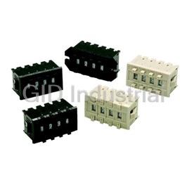
Thumbwheel Switch A7CN/A7CN-L A Brand New Lineup of A7C Series Compact Thumbwheel Switches ■ The series includes a complete range of locking- type models that prevent accidental operation. Ordering Information Switches (Single Switch Units) Model A7CN Screw mounting (back mounting) Snap-in (front mounting) Classification (See note 1.) Terminals PCB terminals Output code number Color Light gray Black Light gray Black 06 (binary coded decimal) --- A7CN-106-1 A7CN-206 A7CN-206-1 Model A7CN-L Snap-in (front mounting) Classification (See note 1.) Locking type Terminals PCB terminals Output code number Color Light gray Black 06 (binary coded decimal) A7CN-L206 A7CN-L206-1 Note: 1. The classification diagrams show 4 Switch Units combined with End Caps to create 4-digit displays. 2. The model numbers given above are for Switch Units. 3. Models with +, - displays can also be produced. Add "-PM" after the "206" in the model number (e.g., A7CN-206-PM or A7CN-206-PM-1). Accessories (Order Separately) Use accessories, such as End Caps and Spacers, with the Switch Units. Screw mounting Classification Snap-in (front mounting) (back mounting) Accessory Color Black Light gray Black End Caps (1 pair) A7CN-1M-1 * A7CN-2M * A7CN-2M-1 * Spacer A7CN-1P@-1 (See note.) A7CN-2P@ (See note.) A7CN-2P@-1 (See note.) Note: The @ in the Spacer model number stands for a letter in the range A to U. (Refer to the table in the following explanation about Spacers.) * The minimum ordering unit is 10. http://www.ia.omron.com/ (c)Copyright OMRON Corporation 2007 All Rights Reserved. 1 A7CN/A7CN-L End Caps End Caps are used on the Switch Units at each end and allow all the Switch Units to be securely mounted to a panel. They come in pairs, one for the left and one for the right. Spacers • Spacers are used for creating extra space or gaps between the Switch Units and have the same dimensions as the Switch Units themselves. • There are also Spacers with engraved characters or symbols that can be used for indicating units, such as time and length. (Refer to the following table.) Consult your OMRON representative for details. Symbol A B C D E F G No desig- Stamp SEC MIN H g kg mm nation Symbol H J K L Q T U Stamp cm m °C PCS x10SEC 0 • Specifications 5 to 28 VDC Switching capacity (resistive load) 1 mA to 0.1 A Continuous carry current 1A Contact resistance 200 mΩ max. Between non-connected 10 MΩ min. (at 250 VDC) terminals Insulation resistance Between terminal and 100 MΩ min. (at 500 VDC) non-current carrying part Between non-connected 200 VAC, 50/60 Hz for 1 min terminals Dielectric strength Between terminal and 1,000 VAC, 50/60 Hz for 1 min non-current carrying part Vibration resistance 10 to 55 Hz, 1.5-mm double amplitude 2 Shock resistance 490m/s min. Mechanical 30,000 operations min. Durability Electrical 20,000 operations min. Operating: -10°C to 65°C (with no icing) Ambient temperature Storage: -20°C to 80°C Ambient humidity Operating: 35% to 85% Max. operating force 4.41 N max. http://www.ia.omron.com/ (c)Copyright OMRON Corporation 2007 All Rights Reserved. 2 A7CN/A7CN-L Dimensions (Unit: mm) Switches (Unit: mm) A7CN-106-1 C Number of Size A Size B Size C PCB Terminals B 15.7 3.5 Switches (n) (n x 6 + 6) (n x 6 + 11) (n x 6 + 16) 4.6 2 A 1 121722 6±0.1 218 23 28 8 P=2.54 324 29 34 4 ±0.2 2 18 16 11.6 2 16 430 35 40 1 C 2.8 536 41 46 0.6±0.2 642 47 52 PCB terminal Panel thickness: 2 748 53 58 2.4 854 59 64 Panel Cutout 960 65 70 10 66 71 76 +0.5 16.2 0 Note: 1. The dimensions above include both End Caps, and will increase 6 mm for each * Spacer inserted. 5.4 +0.7 A 3 0.3 0 Tow, M2.5 or P=6±0.2 2. Unless otherwise specified, a tolerance of M2.6 B A ±0.4 mm applies to all dimensions. * Terminal position dimensions The tolerance for multiple connection is ±(number of units x 0.4) mm. Note: Common terminal C is at the bottom when the Switch Unit is viewed from the front. (Unit: mm) A7CN-206(-1) Number of Size A Size B PCB Terminals 4.9 15.5 Switches (n) (n x 6 + 8) (n x 6 + 6) A 2.2 3.5 114 12 4 6±0.1 220 18 8 P=2.54 326 24 4 ±0.2 2 2 16 18 11.6 1 432 30 C 538 36 ±0.1 0.6 PCB terminal 644 42 Panel thickness: 1 to 2 750 48 2.4 Panel Cutout 856 54 962 60 +0.6 16.2 0 10 68 66 Note: 1. The dimensions above include both End +0.7 B Caps, and will increase 6 mm for each 0 * 5.4 Spacer inserted. 3 0.3 P=6±0.2 2. Unless otherwise specified, a tolerance of B ±0.4 mm applies to all dimensions. * Terminal position dimensions The tolerance for multiple connection is Note: Common terminal C is at the bottom when the Switch Unit is viewed ±(number of units x 0.4) mm. from the front. (Unit: mm) A7CN-L206(-1) 4.7 15.5 Number of Size A Size B PCB Terminals A 2.2 3.5 Switches (n) (n x 6 + 8) (n x 6 + 6) Locking Model 4 6±0.1 114 12 P=2.54 220 18 8 ±0.2 4 1.9 2 18 11.6 16 326 24 1 C 432 30 ±0.2 0.6 When setting 538 36 PCB terminal 644 42 Panel thickness: 1 to 2 750 48 2.4 Panel Cutout 856 54 962 60 +0.6 16.2 10 68 66 0 Note: 1. The dimensions above include both End * +0.7 5.4 Caps, and will increase 6 mm for each B 0 3 0.3 Spacer inserted. P=6±0.2 B 2. Unless otherwise specified, a tolerance of * Terminal position dimensions ±0.4 mm applies to all dimensions. The tolerance for multiple connection is Note: Common terminal C is at the bottom when the Switch Unit is viewed ±(number of units x 0.4) mm. from the front. http://www.ia.omron.com/ (c)Copyright OMRON Corporation 2007 All Rights Reserved. 3 A7CN/A7CN-L Accessories (Order Separately) End Caps for Push-operated Switches End Caps for Push-operated Switches A7CN-1M-1 Screw Mounting A7CN-2M(-1) Snap-in Mounting Left Side Right Side Left Side Right Side 8 8 18 18 18 18 44 2 44 2.2 2 ±0.2 ±0.1 3±0.1 16 ±0.2 2 16 3 2 2 2.2 2.2 13.4 13.4 15.5 15.5 13.6 13.6 15.7 15.7 16 2.7 3±0.1 3 ±0.1 2.7 16 16 3 3 16 Spacers for Push-operated Switches Spacers for Push-operated Switches A7CN-1P@-1 A7CN-2P@(-1) Screw Panel Mounting Model Snap-in Mounting Model ±0.2 18 16 18 16 11.65 ±0.1 13.4 6±0.1 2 6 2 2.25 9 9 Note: The @ in the Spacer model number stands for a letter in the range A to U. Note: The @ in the Spacer model number stands for a letter in the range A to U. (Refer to the table under the explanation about Spacers on page 3.) (Refer to the table under the explanation about Spacers on page 3.) Note: Unless otherwise indicated, dimensional tolerances for dimensions in the models above are ±0.4mm. Output Codes 06 (Binary Code) Terminals connected to common Dial 1 2 4 8 0 1 ● 2 ● 3 ●● 4 ● 5 ●● 6 ●● 7 ●● ● 8 ● 9 ●● Note: The solid dot ● indicates that the internal switch is ON (i.e., connected to the common terminal). Ordering Procedure Place orders as shown in the example below, specifying the model and number. Standard products are not factory-assembled for 1. Switch Unit (snap-in mounting, black) shipment. Contact your OMRON representative for details on A7CN-206-1: 4 pieces ordering factory-assembled sets. 2. Spacer (snap-in mounting, no designation, black) A7CN-2PA-1: 1 piece 3. End Caps (snap-in mounting, black) A7CN-2M-1: 1 pair 3 1 2 1 3 http://www.ia.omron.com/ (c)Copyright OMRON Corporation 2007 All Rights Reserved. 4 A7CN/A7CN-L Safety Precautions Refer to Precautions for Correct Use on in the Technical Guide for Thumbwheel Switches. Precautions for Correct Use Environment Screw-mounting Models • Do not use where gases are generated (ammonia, chlorine, sulfur Tighten mounting screws to a torque between 0.2 to 0.24 N·m, using dioxide). M2.6 screws. Use plain washers or spring washers together with the • Although Switches are of nearly dust-proof construction, they are screws. not drip-proof, therefore do not use in areas subject to water or oil Setting Numbers exposure and do not operate with wet or oily hands. • Provide additional dust-proofing measures, such as using a dust- Locking Type Do not push here proof cover, when using in sand-exposed areas. • Set with the setting button by raising it. • Return the button to its original position Handling after setting. It is then locked to prevent rotation, and the set numbers will not • The A7CN cannot be connected to the A7C. change accidentally. • The molded components of the Switch use polyacetal resin and polycarbonate resin. It is recommended that alcohol is used to wipe Soldering off dirt and smudges from the molded components. Take care to Note the following points when soldering prevent the alcohol from getting inside. printed circuit boards: Do not use thinner or other solutions which might damage the resin. • The terminal insertion holes on the PCB must be at least 1 mm in • When changing settings, do not touch the operating buttons if your diameter. fingers are wet or there is oil or any other foreign substance on your • Automatic Soldering fingers. Do not use dip cleaning. Doing so may result in flux penetration of • Do not drop the individual Switches. Doing so may damage the the Switch interior, causing contact and rotational defects. Clean resin catch (for connecting) on the side of the Switch. the flux as shown in Figure 1, tilting the Switch 80° or less and using • When separating Switches, use a screwdriver as shown in the a brush to apply the solvent only to the back of the board. It may figure below; disconnect them by releasing the top and bottom also be cleaned by dipping only the back of the board into the hooks. Be careful not to bend the hooks. solvent and then using a brush to clean. • Dip Soldering When applying flux solvent, the dipping time is a maximum of 2 seconds. As shown in Figure 2, avoid flooding the top surface of the printed circuit board with flux. Using a brush to apply flux further reduces the danger of flux penetration. When cleaning flux with a brush, tilt the Switch 80° or less, as shown in Figure 1, in order to prevent flux from flowing onto the switch mounting surface. Clean flux as described above under Automatic Soldering. Figure 1 Figure 2 • When connecting Switches, fit the mating parts together. Top surface • Do not push the (+) and (-) operating push-buttons at the same Back surface of board time. of board Models with PCB Terminals Do not use excessive force in handling the Switches. In particular, Wipe away flux 80° or less with a brush. take care to avoid dropping them because the terminals might bend or break. • Using a Soldering Iron Use a 30-W soldering iron at a temperature of 350°C for a maximum of 3 seconds, and flush as described above. Do not apply force to the terminals during soldering and for 3 minutes after soldering is completed. Doing so may result in conduction or operation failure. • Ensure that soldering flux and alcohol do not penetrate into the Switch interior http://www.ia.omron.com/ (c)Copyright OMRON Corporation 2007 All Rights Reserved. 5 Safety Precautions for All Thumbwheel Switches For precautionary information on individual products, refer to Safety Precautions in the relevant section. WARNING Electric shock may possibly occur. Do not perform wiring work or touch the charged parts of terminals while power is supplied to the Switch. Precautions for Correct Use For details, refer to Precautions for Correct Use of Thumbwheel Switches in Technical Guide for Switches and Level Control Equipment. http://www.ia.omron.com/ (c)Copyright OMRON Corporation 2007 All Rights Reserved. C-1 Technical Guide for Thumbwheel Switches Precautions for Correct Use Environment Models with PCB Terminals x Do not use where gases are generated (ammonia, chlorine, sulfur x When using models with PCB terminals, make the terminal dioxide). insertion holes in the back board (mother board) 1 mm or larger in x Although Switches are of nearly dust-proof construction, they are diameter. not drip-proof, therefore do not use in areas subject to water or oil x Do not use excessive force in handling models with PCB terminals. exposure and do not operate with wet or oily hands. (The A7MD In particular, take care to avoid dropping them as the terminals has a dust-proof construction on contact parts, but consider your might bend or break. Reference: Terminals can withstand a force of installation location carefully. The A7MA is not of dust-proof 7.84 N for 1 minute or more (A7D: 4.9 construction.) N for 10 seconds or more), and survive x Provide additional dust-proofing measures, such as using a dust- bending of 20q without breaking after proof cover, when using in sand-exposed areas. returning to original position. Withstanding the repetitive application Storage of external pressure, however, is beyond the scope of Switch Do not store Switches in areas subject to high temperature or high specifications. humidity, or store them in room-temperature areas for extended periods of time. Doing so may cause oxidation of the terminals or Connectors problems with solder. It is also recommended that long periods of x Insert Connectors while keeping the arrow pointing up (refer to storage be avoided in general. A7BS/A7BL and A7PS/A7PH for details). x Connector insertion load is about 14.7 N for each A7B-C and 34.3 Handling N for each NRT-C. x Wiring After wiring has been completed, ensure an appropriate insulation Soldering distance. Note the following points when soldering printed circuit boards: x Set-up x Automatic Soldering Do not use the Switch in the normally-pressed state. Doing so may Do not use dip cleaning. Doing so may result in flux penetration of occasionally result in premature deterioration of parts and changes the Switch interior, causing contact and rotational defects. Clean in the characteristics. the flux as shown in Figure 1, tilting the Switch 80q or less and using x Do not touch charged parts, such as terminals, while the power is a brush to apply the solvent only to the back of the board. It may ON. also be cleaned by dipping only the back of the board into the x Do not connect more than one power supply to a single Switch. solvent and then using a brush to clean. Doing so may result in circuit malfunctions and short-circuits. x Dip Soldering x When changing settings, do not touch the operating buttons if your When applying flux solvent, the dipping time is a maximum of 2 fingers are wet or there is oil or any other foreign substance on your seconds. As shown in Figure 2, avoid flooding the top surface of the fingers. printed circuit board with flux. Using a brush to apply flux further x It is recommended that alcohol is used to wipe off dirt and smudges reduces the danger of flux penetration. When cleaning flux with a from the molded-plastic cases. Take care to prevent the alcohol brush, tilt the Switch 80q or less, as shown in Figure 1, in order to from getting inside. prevent flux from flowing onto the switch mounting surface. Clean x Do not use thinner or other solutions which might damage the flux as described above under Automatic Soldering. plastic. Figure 1 Figure 2 x When connecting Switches, fit the mating parts together. x When separating Switches, use a screwdriver as shown in the Top surface figure below; disconnect them by releasing the top and bottom Back surface of board of board hooks. Be careful not to bend the hooks. Wipe away flux 80° or less with a brush. x Using a Soldering Iron Use a 30-W soldering iron at a temperature of 350qC for a maximum of 3 seconds, and flush as described above. Do not apply force to the terminals during soldering and for 3 minutes after soldering is completed. Doing so may result in x Do not push the (+) and (-) operating push-buttons at the same conduction or operation failure. time. x Ensure that soldering flux and alcohol do not penetrate into the x Do not drop the Switch. Doing so may possibly result in deformation Switch interior of the terminals, damage to the PCB, or damage to the resin catch (for connecting) on the side of the Switch. x The output may be unstable while the pushbuttons are being pressed due to the structure of the Thumbwheel Switch. Read the output signal only after the display has stopped moving. http://www.ia.omron.com/ (c)Copyright OMRON Corporation 2007 All Rights Reserved. C-2 Read and Understand This Catalog Please read and understand this catalog before purchasing the products. Please consult your OMRON representative if you have any questions or comments. Warranty and Limitations of Liability WARRANTY OMRON's exclusive warranty is that the products are free from defects in materials and workmanship for a period of one year (or other period if speciŢ ed) from date of sale by OMRON. OMRON MAKES NO WARRANTY OR REPRESENTATION, EXPRESS OR IMPLIED, REGARDING NON-INFRINGEMENT, MERCHANTABILITY, OR FITNESS FOR PARTICULAR PURPOSE OF THE PRODUCTS. ANY BUYER OR USER ACKNOWLEDGES THAT THE BUYER OR USER ALONE HAS DETERMINED THAT THE PRODUCTS WILL SUITABLY MEET THE REQUIREMENTS OF THEIR INTENDED USE. OMRON DISCLAIMS ALL OTHER WARRANTIES, EXPRESS OR IMPLIED. LIMITATIONS OF LIABILITY OMRON SHALL NOT BE RESPONSIBLE FOR SPECIAL, INDIRECT, OR CONSEQUENTIAL DAMAGES, LOSS OF PROFITS, OR COMMERCIAL LOSS IN ANY WAY CONNECTED WITH THE PRODUCTS, WHETHER SUCH CLAIM IS BASED ON CONTRACT, WARRANTY, NEGLIGENCE, OR STRICT LIABILITY. In no event shall responsibility of OMRON for any act exceed the individual price of the product on which liability is asserted. IN NO EVENT SHALL OMRON BE RESPONSIBLE FOR WARRANTY, REPAIR, OR OTHER CLAIMS REGARDING THE PRODUCTS UNLESS OMRON'S ANALYSIS CONFIRMS THAT THE PRODUCTS WERE PROPERLY HANDLED, STORED, INSTALLED, AND MAINTAINED AND NOT SUBJECT TO CONTAMINATION, ABUSE, MISUSE, OR INAPPROPRIATE MODIFICATION OR REPAIR. Application Considerations SUITABILITY FOR USE OMRON shall not be responsible for conformity with any standards, codes, or regulations that apply to the combination of products in the customer's application or use of the product. At the customer's request, OMRON will provide applicable third party certiŢ cation documents identifying ratings and limitations of use that apply to the products. This information by itself is not sufŢ cient for a complete determination of the suitability of the products in combination with the end product, machine, system, or other application or use. The following are some examples of applications for which particular attention must be given. This is not intended to be an exhaustive list of all possible uses of the products, nor is it intended to imply that the uses listed may be suitable for the products: • Outdoor use, uses involving potential chemical contamination or electrical interference, or conditions or uses not described in this catalog. • Nuclear energy control systems, combustion systems, railroad systems, aviation systems, medical equipment, amusement machines, vehicles, safety equipment, and installations subject to separate industry or government regulations. • Systems, machines, and equipment that could present a risk to life or property. Please know and observe all prohibitions of use applicable to the products. NEVER USE THE PRODUCTS FOR AN APPLICATION INVOLVING SERIOUS RISK TO LIFE OR PROPERTY WITHOUT ENSURING THAT THE SYSTEM AS A WHOLE HAS BEEN DESIGNED TO ADDRESS THE RISKS, AND THAT THE OMRON PRODUCT IS PROPERLY RATED AND INSTALLED FOR THE INTENDED USE WITHIN THE OVERALL EQUIPMENT OR SYSTEM. Disclaimers CHANGE IN SPECIFICATIONS Product speciŢ cations and accessories may be changed at any time based on improvements and other reasons. It is our practice to change model numbers when published ratings or features are changed, or when signiŢ cant construction changes are made. However, some speciŢ cations of the product may be changed without any notice. When in doubt, special model numbers may be assigned to Ţ x or establish key speciŢ cations for your application on your request. Please consult with your OMRON representative at any time to conŢ rm actual speciŢ cations of purchased product. DIMENSIONS AND WEIGHTS Dimensions and weights are nominal and are not to be used for manufacturing purposes, even when tolerances are shown. ERRORS AND OMISSIONS The information in this catalog has been carefully checked and is believed to be accurate; however, no responsibility is assumed for clerical, typographical, or proofreading errors, or omissions. PERFORMANCE DATA Performance data given in this catalog is provided as a guide for the user in determining suitability and does not constitute a warranty. It may represent the result of OMRON’s test conditions, and the users must correlate it to actual application requirements. Actual performance is subject to the OMRON Warranty and Limitations of Liability. PROGRAMMABLE PRODUCTS OMRON shall not be responsible for the user's programming of a programmable product, or any consequence thereof. COPYRIGHT AND COPY PERMISSION This catalog shall not be copied for sales or promotions without permission. This catalog is protected by copyright and is intended solely for use in conjunction with the product. Please notify us before copying or reproducing this catalog in any manner, for any other purpose. If copying or transmitting this catalog to another, please copy or transmit it in its entirety. 2007.3 In the interest of product improvement, specifications are subject to change without notice. OMRON Corporation Industrial Automation Company http://www.ia.omron.com/ (c)Copyright OMRON Corporation 2007 All Rights Reserved.
Frequently asked questions
How does Electronics Finder differ from its competitors?

Is there a warranty for the A7CN-2PB-1?
Which carrier will Electronics Finder use to ship my parts?
Can I buy parts from Electronics Finder if I am outside the USA?
Which payment methods does Electronics Finder accept?
Why buy from GID?

Quality
We are industry veterans who take pride in our work

Protection
Avoid the dangers of risky trading in the gray market

Access
Our network of suppliers is ready and at your disposal

Savings
Maintain legacy systems to prevent costly downtime

Speed
Time is of the essence, and we are respectful of yours
Related Products
Switch Access Push Button Switch Flange A3A-211
Switch Access Push Button Switch Push Button Unit A3BT-500Y
Switch Access Push Button Switch Round Button A3BT-510W
Switch Access Push Button Switch Switch Unit A3BT-7011-1
Switch Access Push Button Switch Round Case A3GT-6021-1
Switch Access Push Button Switch Rectangular Cap A3PJ-5600-A
Request a Quote

The quote request has been received
Close

Facing challenges or have inquiries? Feel free to contact us!
Call Us +1-469-283-2440
What they say about us
FANTASTIC RESOURCE
One of our top priorities is maintaining our business with precision, and we are constantly looking for affiliates that can help us achieve our goal. With the aid of GID Industrial, our obsolete product management has never been more efficient. They have been a great resource to our company, and have quickly become a go-to supplier on our list!
Bucher Emhart Glass
EXCELLENT SERVICE
With our strict fundamentals and high expectations, we were surprised when we came across GID Industrial and their competitive pricing. When we approached them with our issue, they were incredibly confident in being able to provide us with a seamless solution at the best price for us. GID Industrial quickly understood our needs and provided us with excellent service, as well as fully tested product to ensure what we received would be the right fit for our company.
Fuji
HARD TO FIND A BETTER PROVIDER
Our company provides services to aid in the manufacture of technological products, such as semiconductors and flat panel displays, and often searching for distributors of obsolete product we require can waste time and money. Finding GID Industrial proved to be a great asset to our company, with cost effective solutions and superior knowledge on all of their materials, it’d be hard to find a better provider of obsolete or hard to find products.
Applied Materials
CONSISTENTLY DELIVERS QUALITY SOLUTIONS
Over the years, the equipment used in our company becomes discontinued, but they’re still of great use to us and our customers. Once these products are no longer available through the manufacturer, finding a reliable, quick supplier is a necessity, and luckily for us, GID Industrial has provided the most trustworthy, quality solutions to our obsolete component needs.
Nidec Vamco
TERRIFIC RESOURCE
This company has been a terrific help to us (I work for Trican Well Service) in sourcing the Micron Ram Memory we needed for our Siemens computers. Great service! And great pricing! I know when the product is shipping and when it will arrive, all the way through the ordering process.
Trican Well Service
GO TO SOURCE
When I can't find an obsolete part, I first call GID and they'll come up with my parts every time. Great customer service and follow up as well. Scott emails me from time to time to touch base and see if we're having trouble finding something.....which is often with our 25 yr old equipment.
ConAgra Foods