

 Manufacturers
OMRON ELECTRONIC COMPONENTS A7P-PT-1
Description
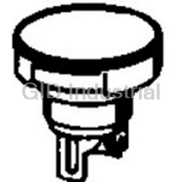
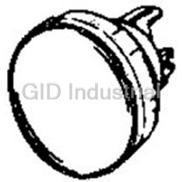
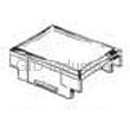
Switch Access Thumbwheel Switch Spacer
A7P-PT-1
Part Number
A7P-PT-1
Price
Request Quote
Manufacturer
OMRON ELECTRONIC COMPONENTS
Lead Time
Request Quote
Category
Sensors and Transducers » Switch Accessories
Specifications
Manufacturer
Omron Electronic Components
Manufacturers Part #
A7P-PT-1
Industry Aliases
A7P-PT-1
Sub-Categories
Switch Accessories
Factory Pack Quantity
200
Datasheet

Extracted Text
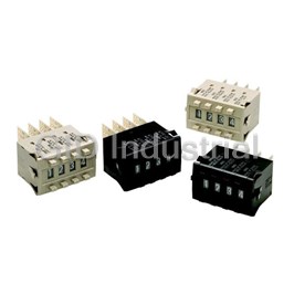
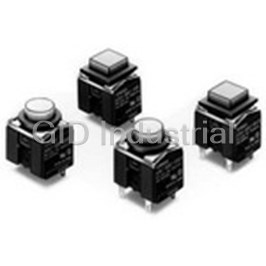
Thumbwheel Switch A7BS/A7BL CSM_A7BS/A7BL_DS_E_6_2 Wide Range of Locking-type Models Available • Character height of 4.8 or 3.2 mm makes for easy-to- view display. Installation is easy with snap-in mounting. The series includes a complete range of locking-type models that prevent accidental operation. Ordering Information Switches (Single Switch Units) Model A7BS A7BS-20@-S Snap-in (front mounting) Snap-in (front mounting) Classification (See note 1.) With external stoppers Character height Decimal: 4.8 mm Hexadecimal: 3.2 mm 4.8 mm Terminals Solder terminals *1 Color Light gray Black Light gray Black Output code number Model 06 (binary coded decimal) A7BS-206 *2 A7BS-206-1 *2 A7BS-206-S A7BS-206-S-1 07 (binary coded decimal, with component A7BS-207 *2 A7BS-207-1 *2 A7BS-207-S A7BS-207-S-1 adding provision) *3 54 (binary coded hexadecimal) A7BS-254 A7BS-254-1 --- --- 55 (binary coded hexadecimal, with A7BS-255 A7BS-255-1 --- --- component-adding provision) *3 Model A7BL Snap-in (front mounting) Classification (See note 1.) Locking type Character height 4.8 mm Terminals Solder terminals *1 Color Light gray Black Output code number Model 06 (binary coded decimal) A7BL-206 *2 A7BL-206-1 *2 07 (binary coded decimal, with component- A7BL-207 *2 A7BL-207-1 *2 adding provision) *3 Note: 1. The classification diagrams show 4 Switch Units combined with End Caps to create 4-digit displays. 2. The model numbers given above are for Switch Units. 3. Models with +, - displays can also be produced. Add “-PM” after the “206” or “207” in the model number (e.g., A7BS-206-PM or A7BS-207-PM-1). *1. For models with PCB terminals, add “-P2” to the model number (e.g., A7BS- 207-P2-1). *2. Models with internal stoppers are also available. Add “-S@@” after the “206” or “207” in the model number and specify the display range in the @@. For example, to specify the range 0 to 6, add “-S06” to the model number (e.g., A7BS-206-S06-1). For structural reasons, models with stoppers cannot be manufactured for the A7BS-254 and A7BS-255. *3. Models with diodes are available. Add “-D” to the model number (e.g., A7BS- 207-D or A7BS-207-D-1). 1 A7BS/A7BL Accessories (Order Separately) Use accessories, such as End Caps, Spacers, and Connectors with the Switch Units. End Caps, Spare Units, and Connectors Accessory Color Light gray Black End Caps (1 pair) A7B-M A7B-M-1 Spacer A7B-P@ (See note.) A7B-P@-1 (See note.) Solder terminals A7B-C Connectors PCB terminals A7B-CP Note: The @ in the Spacer model number stands for a letter in the range A to U. (Refer to the table in the following explanation about Spacers.) End Caps Spacers End Caps are used on the Switch Units at each end and allow all the • Spacers are used for creating extra space or gaps between the Switch Units to be securely mounted to a panel. They come in pairs, Switch Units and have the same dimensions as the Switch Units one for the left and one for the right. themselves. • There are also Spacers with engraved characters or symbols that can be used for indicating units, such as time and length. (Refer to the following table.) Consult your OMRON representative for details. Symbol A B C D E F G No des- Stamp SEC MIN H g kg mm ignation Symbol H J K L Q T U x 10 Stamp cm m °CPCS 0 SEC Specifications 3.3 to 28 VDC or 50 VAC Switching capacity (resistive load) 1 mA to 0.1 A Continuous carry current 1 A max. Contact resistance 300 mΩ max. Between non-connected 10 MΩ min. (at 500 VDC) terminals Insulation resistance Between terminal and 1,000 MΩ min. (at 500 VDC) non-current carrying part Between non-connected 600 VAC, 50/60 Hz for 1 min terminals Dielectric strength Between terminal and 1,000 VAC, 50/60 Hz for 1 min non-current carrying part Vibration resistance 10 to 55 Hz, 1.5-mm double amplitude 2 Shock resistance 490 m/s min. Mechanical 100,000 operations min. Durability Electrical 50,000 operations min. Operating: -10°C to 65°C (with no icing) Ambient temperature Storage: -20°C to 80°C Ambient humidity Operating: 45% to 85% Max. operating force 5.39 N max. 2 A7BS/A7BL Dimensions (Unit: mm) Switches A7BS-2@@(-1) 5.5 * Number of 24.5 Size A Size B A 2.8 Solder Terminals ±0.1 8 Switches Size C (n x 8 + 8) (n x 8 + 6) (n) 1 16 14 14.4 2 24 22 22.4 24 16 2.6 20.6 22 3 32 30 30.4 4 40 38 38.4 5 48 46 46.8 Solder terminal 6 56 54 54.8 7 64 62 62.8 Panel thickness: 1 to 3 8 72 70 70.8 * If the output code is 06 or 54, the dimension is 32.5; 9 80 78 78.8 3.8 if the output code is 07 or 55, the dimension is 43.5. 10 88 86 86.8 Note: 1. The dimensions above include both End Caps, and will increase 8 mm for each Panel Cutout Spacer inserted. 2. Unless otherwise specified, a tolerance of +0.4 ±0.4 mm applies to all dimensions. 22.4 0 The tolerance for multiple connection is ±(number of units x 0.4) mm. 3 0.8 6.9 +0.3 ±0.2 P=8 C 0 B Thumbwheel Switches with External Stoppers: A7BS-20@-S(-1) Stopper Pins • Use A7BS-S Stopper Pins to make dial display restrictions for these Switches. • Insert the Stopper Pins in the positions required to give the desired display range. For 1.2 dia. 2.4 dia. example, for a display range of 0 to 5, insert a Stopper Pin at position 1 (see following 0.4 diagram) to stop the display from going above 5 when the (+) button is pressed, and insert 2.7 a Stopper Pin at position 2 to stop the display from going below 0 when the (-) button is Note: 1. Two pins constitute one set. pressed. 2. The first shipment is free and is attached Refer to page 7 for details. to the Switch. Order the A7BS-S separately if it is 5.5 required for maintenance. * 2.8 24.5 Pin insertion position (2) 9 0 9 0 8 1 1 8 7 2 22 20.6 16 24 7 2 6 3 6 3 5 4 2.6 5 4 Pin insertion position (1) Ten, 1.2 dia. * If the output code is 06, the dimension is 32.5; if the output code is 07, the dimension is 43.5. A7BL-206(-1) Number of Size A Size B 6.1 * Switches Size C A7BL-207(-1) A (n x 8 + 8) (n x 8 + 6) ±0.1 2.8 24.5 8 (n) Solder Terminals, 1 16 14 14.4 Locking Models 2 24 22 22.4 3 32 30 30.4 24 15.4 2 20.6 22 4 40 38 38.4 5 48 46 46.8 Solder terminal 6 56 54 54.8 When setting 7 64 62 62.8 Panel thickness: 1 to 3 8 72 70 70.8 * If the output code is 06, the dimension is 32.5; 3.6 9 80 78 78.8 if the output code is 07, the dimension is 43.5. 10 88 86 86.8 Note: 1. The dimensions above include both End Panel Cutout Caps, and will increase 8 mm for each Spacer inserted. 2. Unless otherwise specified, a tolerance of +0.4 22.4 0 ±0.4 mm applies to all dimensions. The tolerance for multiple connection is ±(number of units x 0.4) mm. 3 0.8 +0.3 6.9 ±0.2 P=8 C 0 B 3 UP UP A7BS/A7BL Accessories (Order Separately) End Caps for Push-operated Switches A7B-M(-1) Snap-in Panel Mounting (30) (30) Left Side Right Side 24 24 2.8 2.8 3.2 4 4 3.2 24.5 24.5 2.4 (3.5) 3 (3.5) 22 3 22 3 Spacers for Push-operated Switches A7B-P@(-1) Snap-in Panel Mounting 24 22 2.8 24.5 3 ±0.1 8 The @ in the Spacer model number stands for a letter in the range A to U. (Refer to the table under the explanation about Spacers on page 2.) Note: Unless otherwise indicated, dimensional tolerances for dimensions in the models above are ± 0.4 mm. Connectors (These devices allow Switches to be quickly removed for maintenance and inspection of connectivity, and quickly re-installed.) A7B-C 37 31 Solder Terminals 24 3.3 dia. 21 7.8 Inserting Connectors Insert Connectors with the “UP” arrow 9 13.5 pointing up. 20.5 P=2.54 3 1 3 5 7 2 4 6 22 A7B-CP 24 PCB Terminals 21 7.8 Connector 9 13.5 17.5 0.6 x 0.6 3 P = 2.54 1 3 5 7 2 4 6 22 Note: Unless otherwise indicated, dimensional tolerances for dimensions in the models above are ± 0.4 mm. 4 A7BS/A7BL Output Codes/Terminals • Switches with output codes 06 or 07 both use binary coded decimal • How to Read Output Codes but Switches with output code 07 have a component-adding For example, when the dial position is “3,” the common terminal C provision. Similarly, Switches with output codes 54 or 55 both use on the Switch is connected to terminals 1 and 2. When the Switch binary coded hexadecimal but Switches with output code 55 have is inserted into the Connector, the common terminal C becomes a component-adding provision. connector terminal 2, and terminals 1 and 2 become connector terminals 4 and 5 respectively. Output code Terminals Output codes number Switch Unit or Common ter- Terminals connected to Model Connector minal number common 06 Switch Unit C 1 2 4 8 06 Connector 2 4 5 6 7 Fourteen, 1-dia. holes 07 Connector 1 4 5 6 7 0 1 ● 2 ● 3 ●● 4 ● Dial 5 ●● 6 ●● 7 ●● ● 8 ● 9 ●● 07 Note: The solid dot ● indicates that the internal switch is ON Twenty-eight, (i.e., connected to the common terminal). 1-dia. holes Component-adding provision 5 A7BS/A7BL Output code Terminals Output codes number Switch Unit or Common ter- Terminals connected to Model Connector minal number common Switch Unit C 1 2 4 8 54 Connector 2 4 5 6 7 54 55 Connector 1 4 5 6 7 0 Fourteen, 1 ● 1-dia. holes 2 ● 3 ●● 4 ● 5 ●● 6 ●● 7 ●● ● Dial 8 ● 9 ●● A ●● B ●● ● C ●● 55 D ●● ● E ●● ● Twenty-eight, 1-dia. holes F ●● ●● Component-adding provision Note: 1. The solid dot ● indicates that the internal switch is ON (i.e., connected to the common terminal). 6 A7BS/A7BL Ordering Procedure Place orders as shown in the example below, specifying the model and number. Standard products are not factory-assembled for shipment. Contact your OMRON representative for details on ordering factory-assembled sets. 43 1 24 1. A7BS-206 (Switch Unit): 2 pieces 2. A7BS-207 (Switch Unit): 2 pieces 3. A7B-PA (Spacer): 1 piece 4. A7B-M (End Caps): 1 pair Safety Precautions Refer to Precautions for Correct Use on page in the Technical Guide for Thumbwheel Switches. Precautions for Correct Use Handling Models with External Stoppers (A7BS-20@-S) • The molded components of the Switch use polyacetal resin and With the A7BS-20@-S, any range can be set externally using the ABS resin. It is recommended that alcohol is used to wipe off dirt Stopper Pin. Insert the Stopper Pin using the following procedure: and smudges from the molded components. Take care to prevent the alcohol from getting inside. (2) Stopper Pin (lower limit) (3) Stopper Pin (upper limit) • A7BS/A7BL Thumbwheel Switches are not drip-proof. Do not use them in areas subject to water or oil. • Do not allow solder flux or alcohol to enter the Switch. (1) Display window Setting Numbers Locking Type Example: To Display the Range 0 to 7 1. Any number within the range of (0 to 7) can be chosen to limit the numbers displayed in the display window. (In this example, 8 and 9 are outside of this range.) 2. First, insert the Stopper Pin in the hole in front of the lower limit (“0”) for the • Set with the setting button by raising it. number to be defined. • Return the button to its original position after setting. It is then 3. Next, inset the Stopper Pin in the hole locked to prevent rotation, and the set numbers will not change past the upper limit (“7”) for the number accidentally. to be defined. (The Stopper Pins then • To separate the Switches, use a flat-blade screwdriver as shown in surround the exact range to be the following figure to release the hooks on the top and bottom and defined.) then separate the Switches. Be careful not to bend the hooks. 4. Confirm that the (+) push-button can no longer be pushed after reaching the upper limit of (“7”). 5. Confirm that the (-) push-button can no longer be pushed after reaching the lower limit of (“0”). This completes the setting. 7 Terms and Conditions Agreement Read and understand this catalog. Please read and understand this catalog before purchasing the products. Please consult your OMRON representative if you have any questions or comments. Warranties. (a) Exclusive Warranty. Omron’s exclusive warranty is that the Products will be free from defects in materials and workmanship for a period of twelve months from the date of sale by Omron (or such other period expressed in writing by Omron). Omron disclaims all other warranties, express or implied. (b) Limitations. OMRON MAKES NO WARRANTY OR REPRESENTATION, EXPRESS OR IMPLIED, ABOUT NON-INFRINGEMENT, MERCHANTABILITY OR FITNESS FOR A PARTICULAR PURPOSE OF THE PRODUCTS. BUYER ACKNOWLEDGES THAT IT ALONE HAS DETERMINED THAT THE PRODUCTS WILL SUITABLY MEET THE REQUIREMENTS OF THEIR INTENDED USE. Omron further disclaims all warranties and responsibility of any type for claims or expenses based on infringement by the Products or otherwise of any intellectual property right. (c) Buyer Remedy. Omron’s sole obligation hereunder shall be, at Omron’s election, to (i) replace (in the form originally shipped with Buyer responsible for labor charges for removal or replacement thereof) the non-complying Product, (ii) repair the non-complying Product, or (iii) repay or credit Buyer an amount equal to the purchase price of the non-complying Product; provided that in no event shall Omron be responsible for warranty, repair, indemnity or any other claims or expenses regarding the Products unless Omron’s analysis confirms that the Products were properly handled, stored, installed and maintained and not subject to contamination, abuse, misuse or inappropriate modification. Return of any Products by Buyer must be approved in writing by Omron before shipment. Omron Companies shall not be liable for the suitability or unsuitability or the results from the use of Products in combination with any electrical or electronic components, circuits, system assemblies or any other materials or substances or environments. Any advice, recommendations or information given orally or in writing, are not to be construed as an amendment or addition to the above warranty. See http://www.omron.com/global/ or contact your Omron representative for published information. Limitation on Liability; Etc. OMRON COMPANIES SHALL NOT BE LIABLE FOR SPECIAL, INDIRECT, INCIDENTAL, OR CONSEQUENTIAL DAMAGES, LOSS OF PROFITS OR PRODUCTION OR COMMERCIAL LOSS IN ANY WAY CONNECTED WITH THE PRODUCTS, WHETHER SUCH CLAIM IS BASED IN CONTRACT, WARRANTY, NEGLIGENCE OR STRICT LIABILITY. Further, in no event shall liability of Omron Companies exceed the individual price of the Product on which liability is asserted. Suitability of Use. Omron Companies shall not be responsible for conformity with any standards, codes or regulations which apply to the combination of the Product in the Buyer’s application or use of the Product. At Buyer’s request, Omron will provide applicable third party certification documents identifying ratings and limitations of use which apply to the Product. This information by itself is not sufficient for a complete determination of the suitability of the Product in combination with the end product, machine, system, or other application or use. Buyer shall be solely responsible for determining appropriateness of the particular Product with respect to Buyer’s application, product or system. Buyer shall take application responsibility in all cases. NEVER USE THE PRODUCT FOR AN APPLICATION INVOLVING SERIOUS RISK TO LIFE OR PROPERTY OR IN LARGE QUANTITIES WITHOUT ENSURING THAT THE SYSTEM AS A WHOLE HAS BEEN DESIGNED TO ADDRESS THE RISKS, AND THAT THE OMRON PRODUCT(S) IS PROPERLY RATED AND INSTALLED FOR THE INTENDED USE WITHIN THE OVERALL EQUIPMENT OR SYSTEM. Programmable Products. Omron Companies shall not be responsible for the user’s programming of a programmable Product, or any consequence thereof. Performance Data. Data presented in Omron Company websites, catalogs and other materials is provided as a guide for the user in determining suitability and does not constitute a warranty. It may represent the result of Omron’s test conditions, and the user must correlate it to actual application requirements. Actual performance is subject to the Omron’s Warranty and Limitations of Liability. Change in Specifications. Product specifications and accessories may be changed at any time based on improvements and other reasons. It is our practice to change part numbers when published ratings or features are changed, or when significant construction changes are made. However, some specifications of the Product may be changed without any notice. When in doubt, special part numbers may be assigned to fix or establish key specifications for your application. Please consult with your Omron’s representative at any time to confirm actual specifications of purchased Product. Errors and Omissions. Information presented by Omron Companies has been checked and is believed to be accurate; however, no responsibility is assumed for clerical, typographical or proofreading errors or omissions. 2016.4 In the interest of product improvement, specifications are subject to change without notice. OMRON Corporation Industrial Automation Company http://www.ia.omron.com/ (c)Copyright OMRON Corporation 2016 All Right Reserved.
Frequently asked questions
How does Electronics Finder differ from its competitors?

Is there a warranty for the A7P-PT-1?
Which carrier will Electronics Finder use to ship my parts?
Can I buy parts from Electronics Finder if I am outside the USA?
Which payment methods does Electronics Finder accept?
Why buy from GID?

Quality
We are industry veterans who take pride in our work

Protection
Avoid the dangers of risky trading in the gray market

Access
Our network of suppliers is ready and at your disposal

Savings
Maintain legacy systems to prevent costly downtime

Speed
Time is of the essence, and we are respectful of yours
Related Products
Switch Access Push Button Switch Flange A3A-211
Switch Access Push Button Switch Push Button Unit A3BT-500Y
Switch Access Push Button Switch Round Button A3BT-510W
Switch Access Push Button Switch Switch Unit A3BT-7011-1
Switch Access Push Button Switch Round Case A3GT-6021-1
Switch Access Push Button Switch Rectangular Cap A3PJ-5600-A
Request a Quote

The quote request has been received
Close

Facing challenges or have inquiries? Feel free to contact us!
Call Us +1-469-283-2440
What they say about us
FANTASTIC RESOURCE
One of our top priorities is maintaining our business with precision, and we are constantly looking for affiliates that can help us achieve our goal. With the aid of GID Industrial, our obsolete product management has never been more efficient. They have been a great resource to our company, and have quickly become a go-to supplier on our list!
Bucher Emhart Glass
EXCELLENT SERVICE
With our strict fundamentals and high expectations, we were surprised when we came across GID Industrial and their competitive pricing. When we approached them with our issue, they were incredibly confident in being able to provide us with a seamless solution at the best price for us. GID Industrial quickly understood our needs and provided us with excellent service, as well as fully tested product to ensure what we received would be the right fit for our company.
Fuji
HARD TO FIND A BETTER PROVIDER
Our company provides services to aid in the manufacture of technological products, such as semiconductors and flat panel displays, and often searching for distributors of obsolete product we require can waste time and money. Finding GID Industrial proved to be a great asset to our company, with cost effective solutions and superior knowledge on all of their materials, it’d be hard to find a better provider of obsolete or hard to find products.
Applied Materials
CONSISTENTLY DELIVERS QUALITY SOLUTIONS
Over the years, the equipment used in our company becomes discontinued, but they’re still of great use to us and our customers. Once these products are no longer available through the manufacturer, finding a reliable, quick supplier is a necessity, and luckily for us, GID Industrial has provided the most trustworthy, quality solutions to our obsolete component needs.
Nidec Vamco
TERRIFIC RESOURCE
This company has been a terrific help to us (I work for Trican Well Service) in sourcing the Micron Ram Memory we needed for our Siemens computers. Great service! And great pricing! I know when the product is shipping and when it will arrive, all the way through the ordering process.
Trican Well Service
GO TO SOURCE
When I can't find an obsolete part, I first call GID and they'll come up with my parts every time. Great customer service and follow up as well. Scott emails me from time to time to touch base and see if we're having trouble finding something.....which is often with our 25 yr old equipment.
ConAgra Foods